Banner Image

Dane Kouttron

Project Started: 07/2023

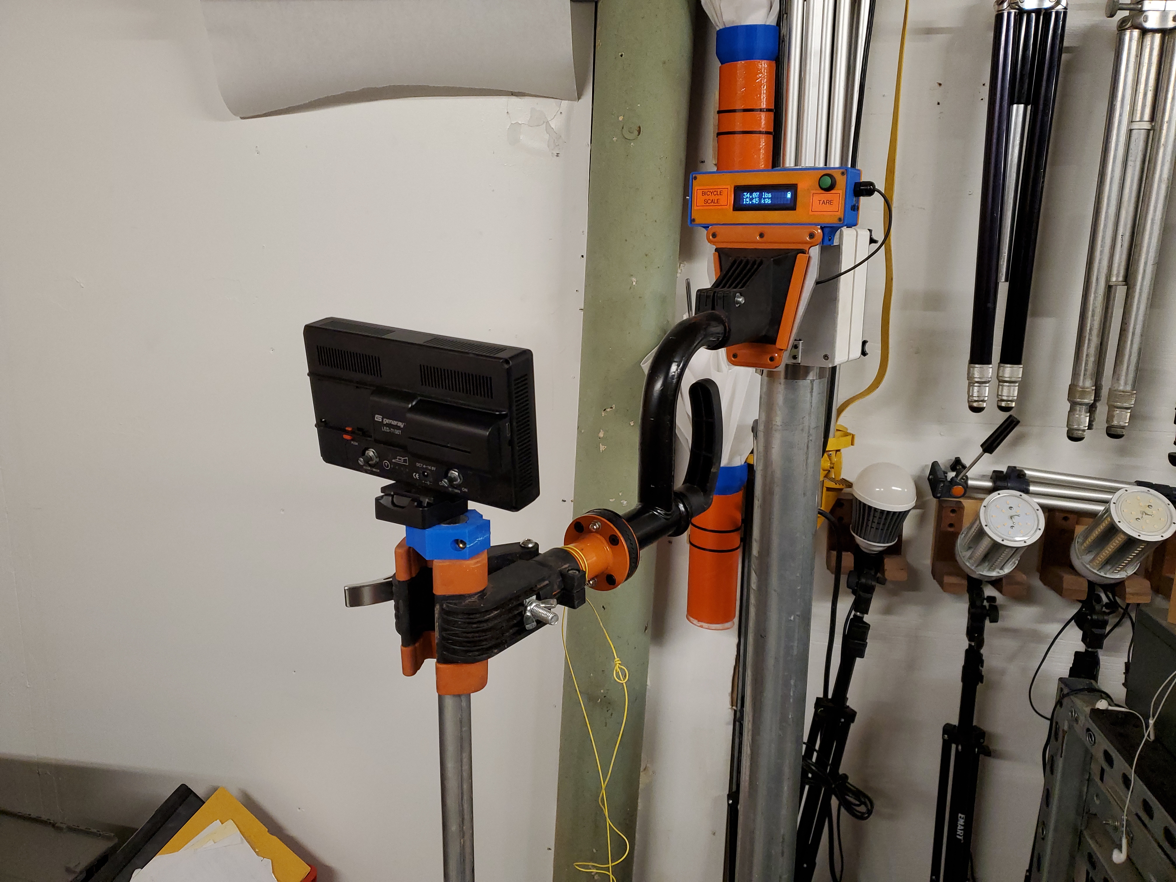
Weebles wobble but can they prevent my photography lights from getting smashed?

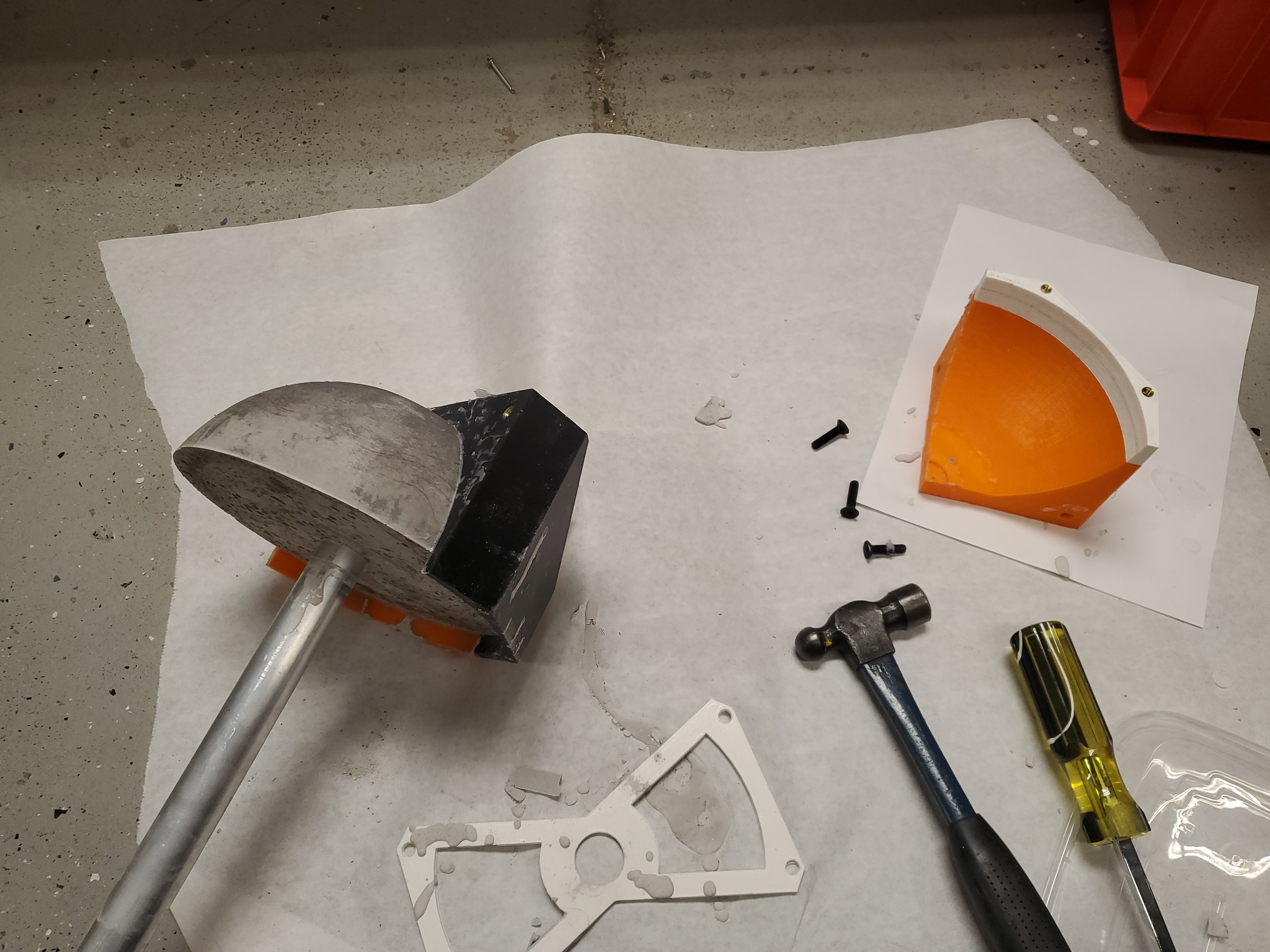
I spotted a recent Colin Furze video, in which he built a life sized counterweight swing using cement and a large steel post. Can the same topology be applied to conventional photography?

In a cramped shop space its not too uncommon to knock over a tripod, especially if its awkwardly between you and the thing you're trying to film. Trying to get that lathe shot but then tripping on something only to knock over a light or worse somewhat sucks.

Some plotting continues

For some refernce material, here's a colin furze sized weeble wobble, using standard concrete. The goal is to make an easy-to-cast cement/concrete 'weeble' and attach it to a mast such that cameras or lights can be attached.

How large of a casting do you need? How heavy should it be?

Excellent questions, Lets make a derpy diagram with a few simplifications:

For reasons of un-simplicity I'm going to use the imperial unit system

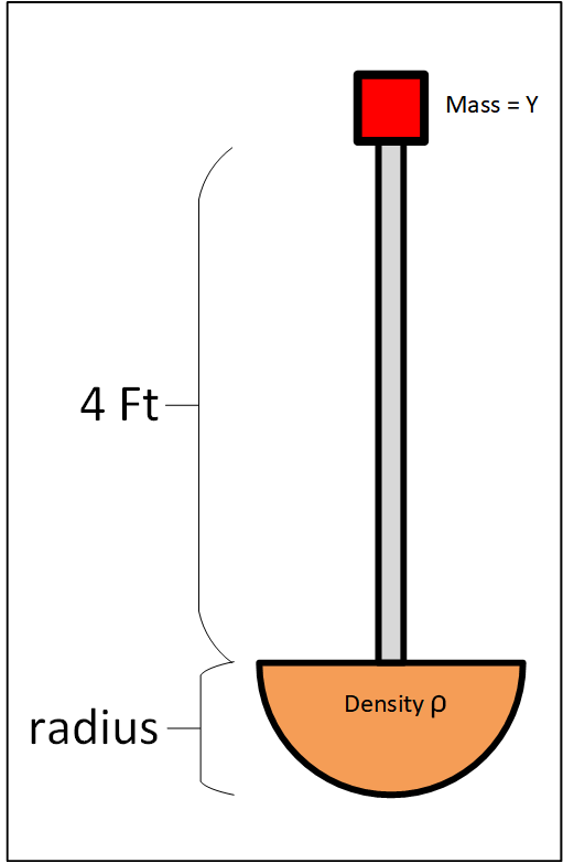
To keep a weight of Y pounds at the end of the pole vertical, the center of gravity of the entire system (pole + half sphere) must be directly below the point where the weight is located. This will ensure that the weight does not cause the system to tilt or topple over. For the sake of this we can ignore the mass of the upright pole so the center of gravity will be located at the center of the half sphere. The center of gravity of the entire system should be at the same height as the weight.
Now, let's calculate the size of the half sphere needed. We know that the camera light / camera / weight is at a height of h feet from the ground, the center of the half sphere must be at the same height h to maintain equilibrium.
The distance from the center of the half sphere to the weight is the sum of the height of the weight (h) and the length of the pole (4 feet). So, the radius of the half sphere can be calculated as:
Radius = h + 4 feet

Now, let's solve for h in terms of Y:

The weight y exerts a torque around the center of the half sphere. Torque is the product of force and the perpendicular distance from the point of rotation (center of the half sphere) to the line of action of the force. In this case, the torque due to the weight Y is balanced by the torque due to the half sphere, which is quivalent to the weight of the half sphere acting at its center.
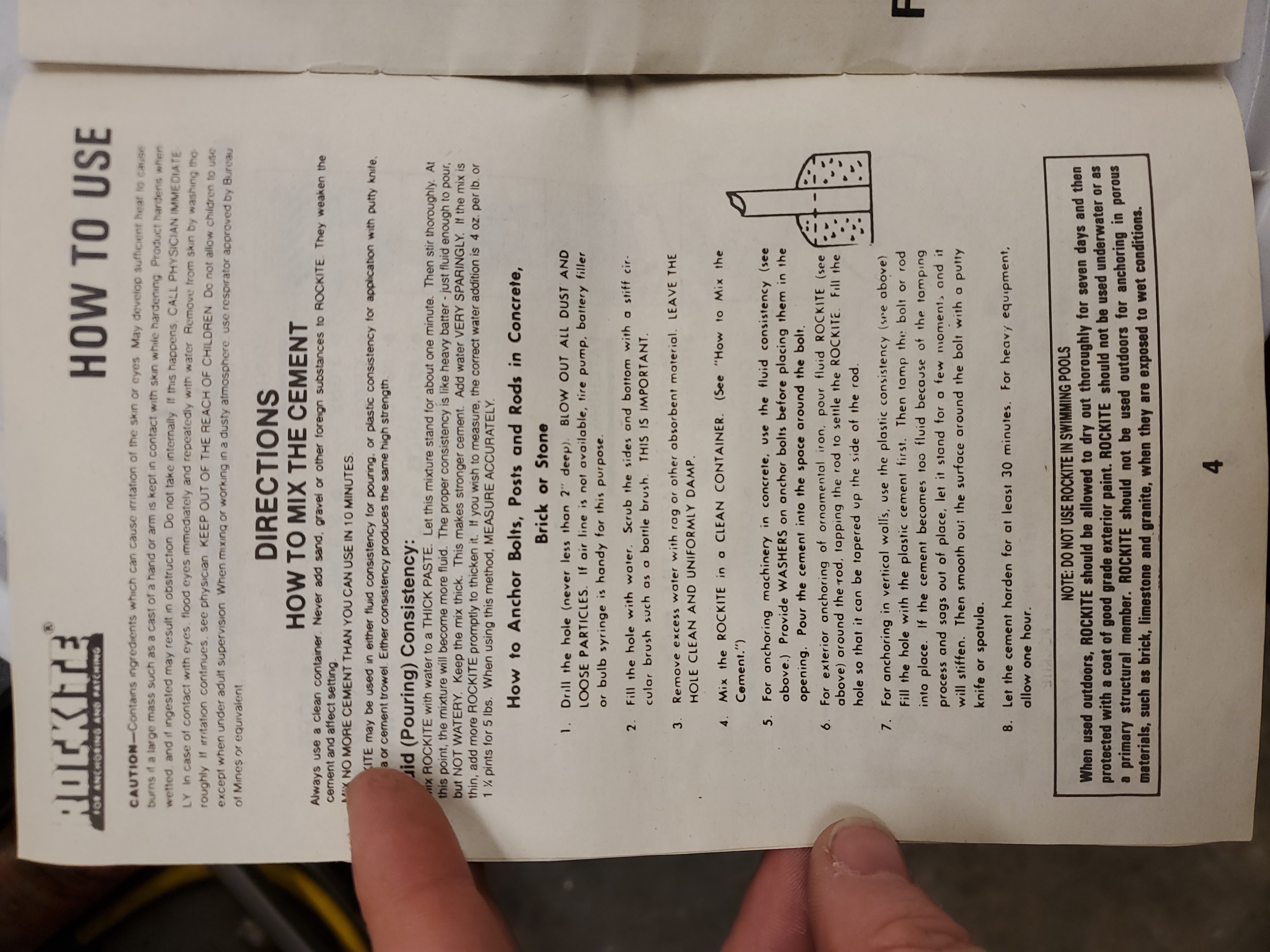
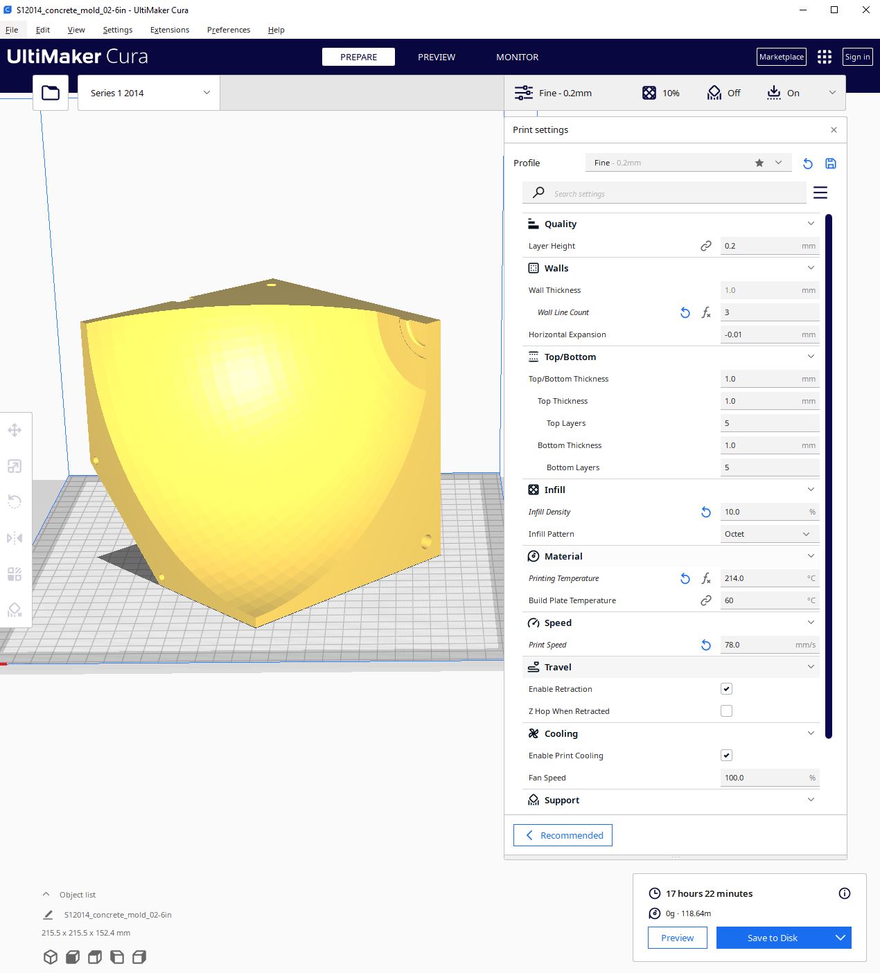
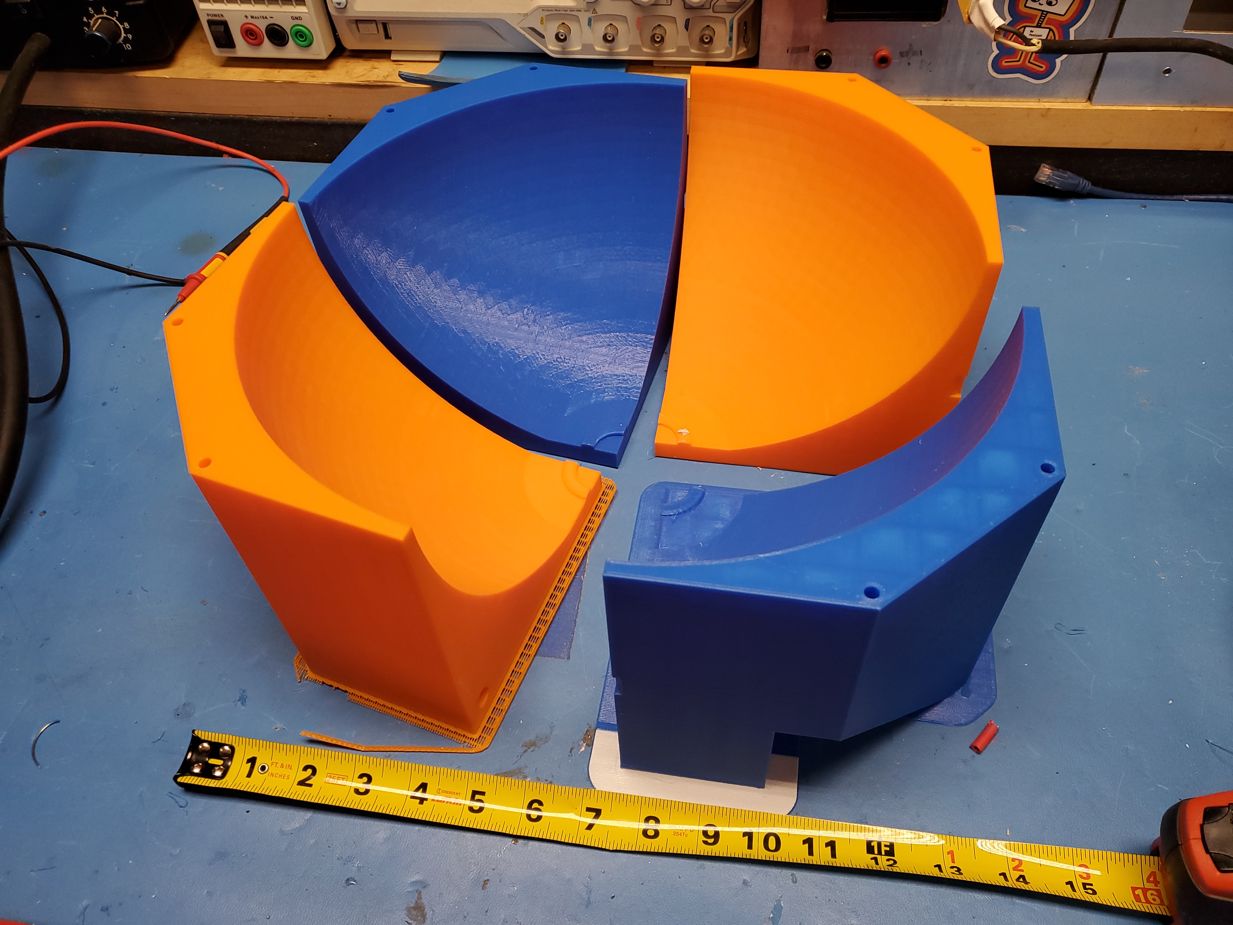
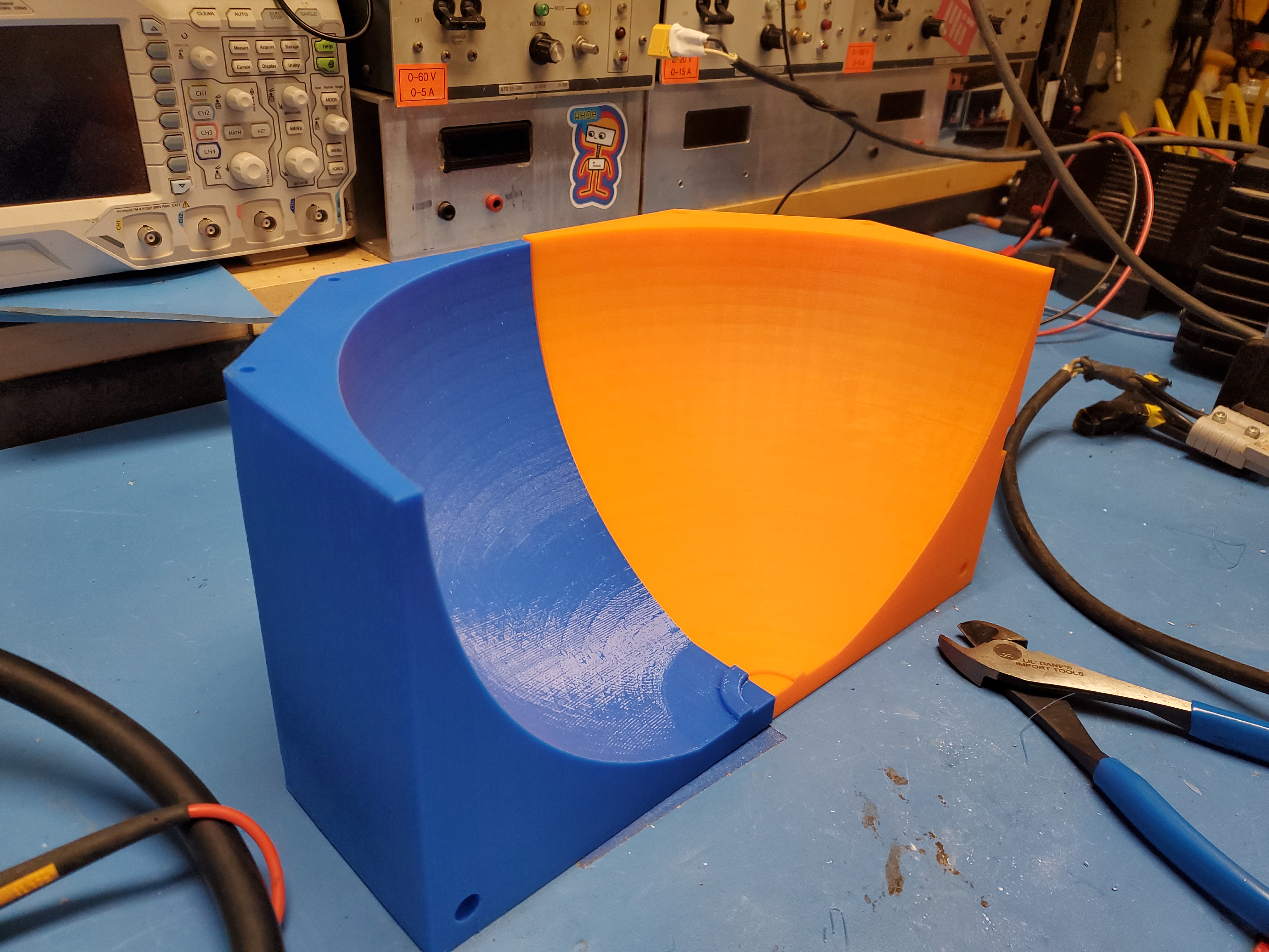
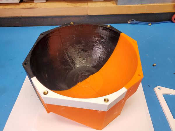
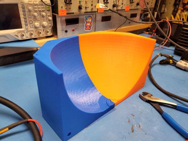
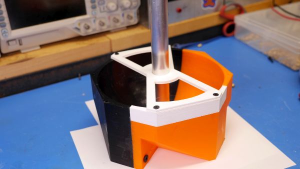
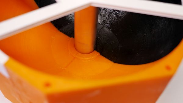
The torque due to the weight Y is Y * 4 feet.

The torque due to the half sphere is the weight of the half sphere, which can be calculated as the product of its mass and the acceleration due to gravity (9.8 m/s^2 or 32.2 ft/s^2).
The mass of the half sphere can be calculated using its volume and the density of concrete. Let's assume the density of concrete is ρ (in pounds per cubic foot).

The volume of a half sphere with radius r is (2/3) * π * r^3. Therefore, the volume of the half sphere is (2/3) * π * (radius^3).

The mass of the half sphere is the product of its volume and density: (2/3) * π * (radius^3) * ρ.

Now, let's set up the equation for torque equilibrium:

y * 4 feet = (2/3) * π * (radius^3) * ρ * 32.2 ft/s^2

Simplifying the equation, we can solve for the radius:

radius^3 = (3 * y * 4 feet) / (2 * π * ρ * 32.2 ft/s^2)

radius = (3 * y * 4 feet / (2 * π * ρ * 32.2 ft/s^2))^(1/3)

Let's start CADDING

For a camera that weighs 2 lbs I need a 28 lb mass, or a roughly 3.96 inch radius sphere on a 4ft pole, using the provided concrete density. This ignores the mass of the pole. Lets print a mold for a concrete casting. Because this casting is somewhat large, and to avoid extended long duration prints I split it into four parts. Our maths told us that a very dense steel-concrete mix should allow us the mass required to fit everything in a 4" radius half-sphere. The nice part about a sphere this small is that it is printable in sections on a budget printer (makerbot, ender 3, etc).

Note that you see large flat surfaces only held together by a single screw on the base. I debated included more guidance features, however, given that it was going to sit on a flat surface as an alignment feature, it did not seem necessary. I installed a single M6 thermal insert, into one side of the print, with the other side accepting the diameter of the mating screw.

With some more printing, we now have the four parts, surprisingly well matched. Note that as this is a mold, I opted to use whatever filament spools were incomplete so some parts are different colors.

A copy of the STL for this 4" radius model is available here: [link]

Before connecting the four molds, I used (possibly too much) RTV silicone sealant between the faces. This provides a seal and helps prevent the concrete mix from escaping down the seams. Given how surprisingly flat these were, the amount of silicone on the face seal required was surprisingly small. As shown below the excess was wiped off inside. I ended up applying more inside the mold and it worked remarkably well as a mold release agent. No brush was necessary, just a gloved finger pressing it into place.

With the mold setup, and some time to let the RTV silicone to cure it was time for the first pour. I didn't want to waste the steel shot on the first go, especially if the mold was going to end up leaking, so I opted to pour just a fast-dry concrete-water mix. This should tell me how well the mold holds the mixture, what the surface comes out like, how well the aluminum pole is retained and how perpendicular it turned out.

For concrete I opted to use this stuff as it was leftover from a lab storage room. Its fairly retro looking, but it was still powdery and dry so may as well put it to use. I was mostly interested in the fast-curing '15 minute' note. I did not observe any of the 'expanding' features. Realistically any non-aggregate cement mix should work well. I was tipped off to use glass fiber cuttings for reinforcement to help prevent chipping, and might go this route depending on how the 'dense' cement casting goes.

figure from paper figure from paper

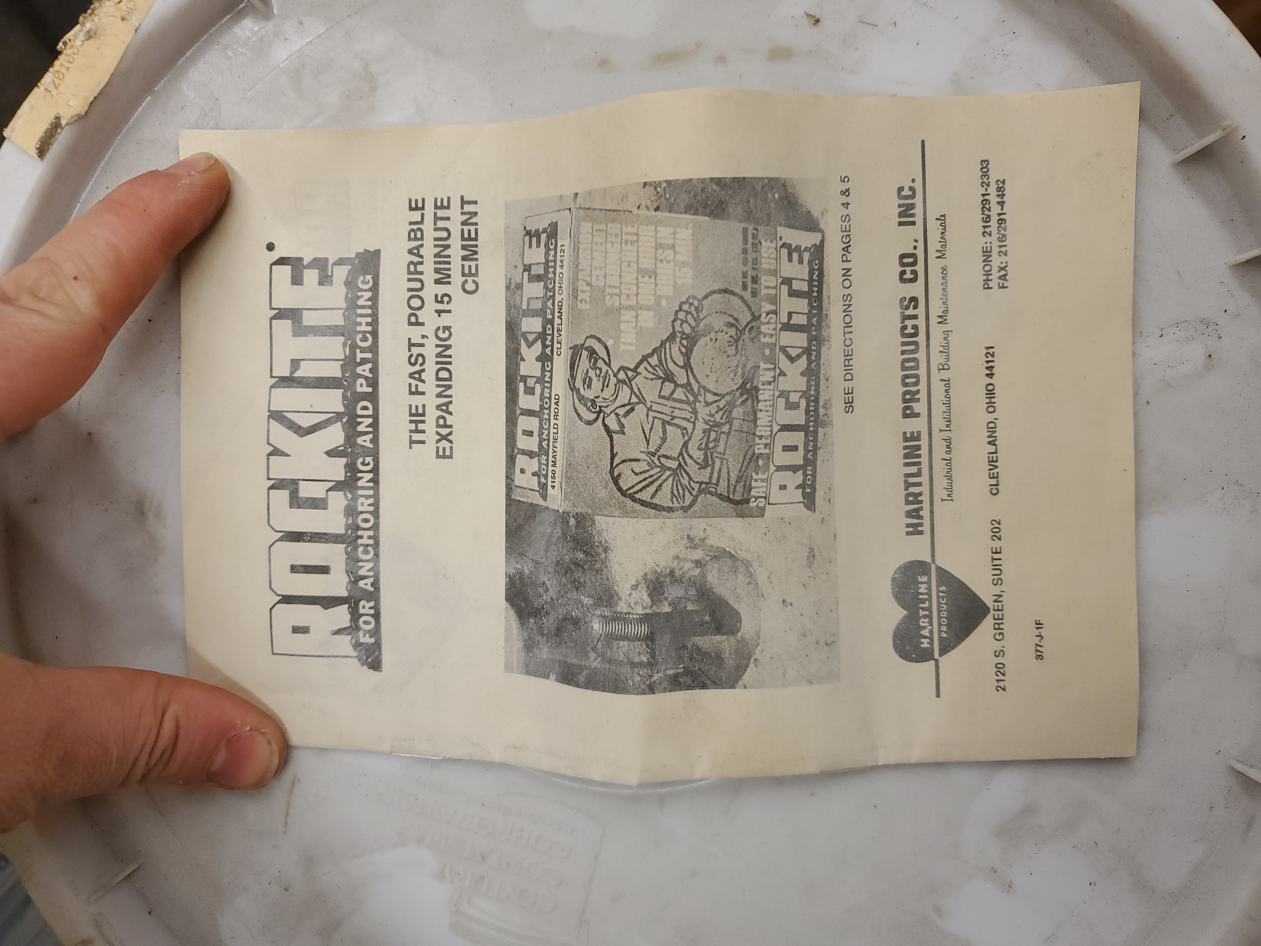
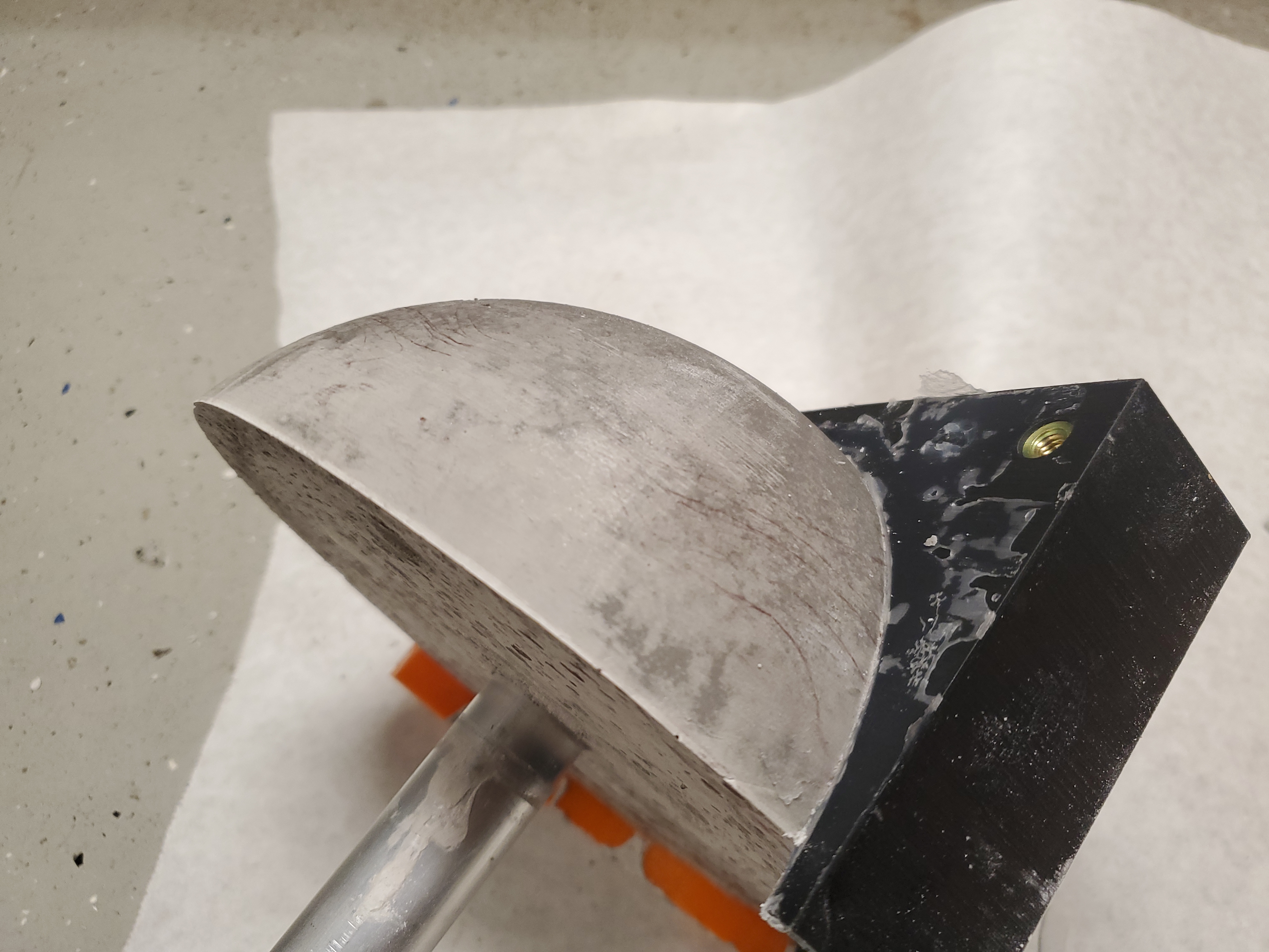
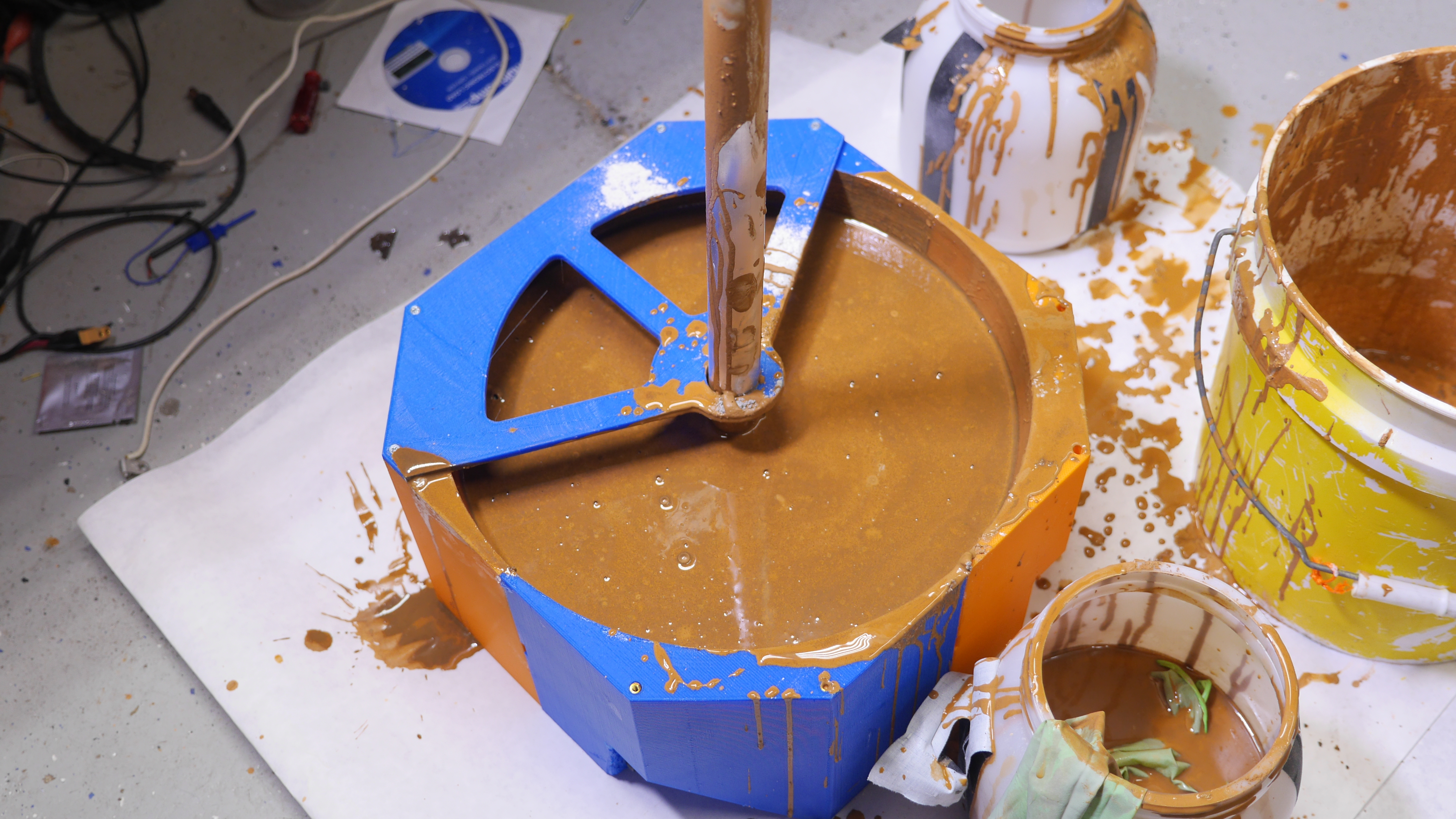
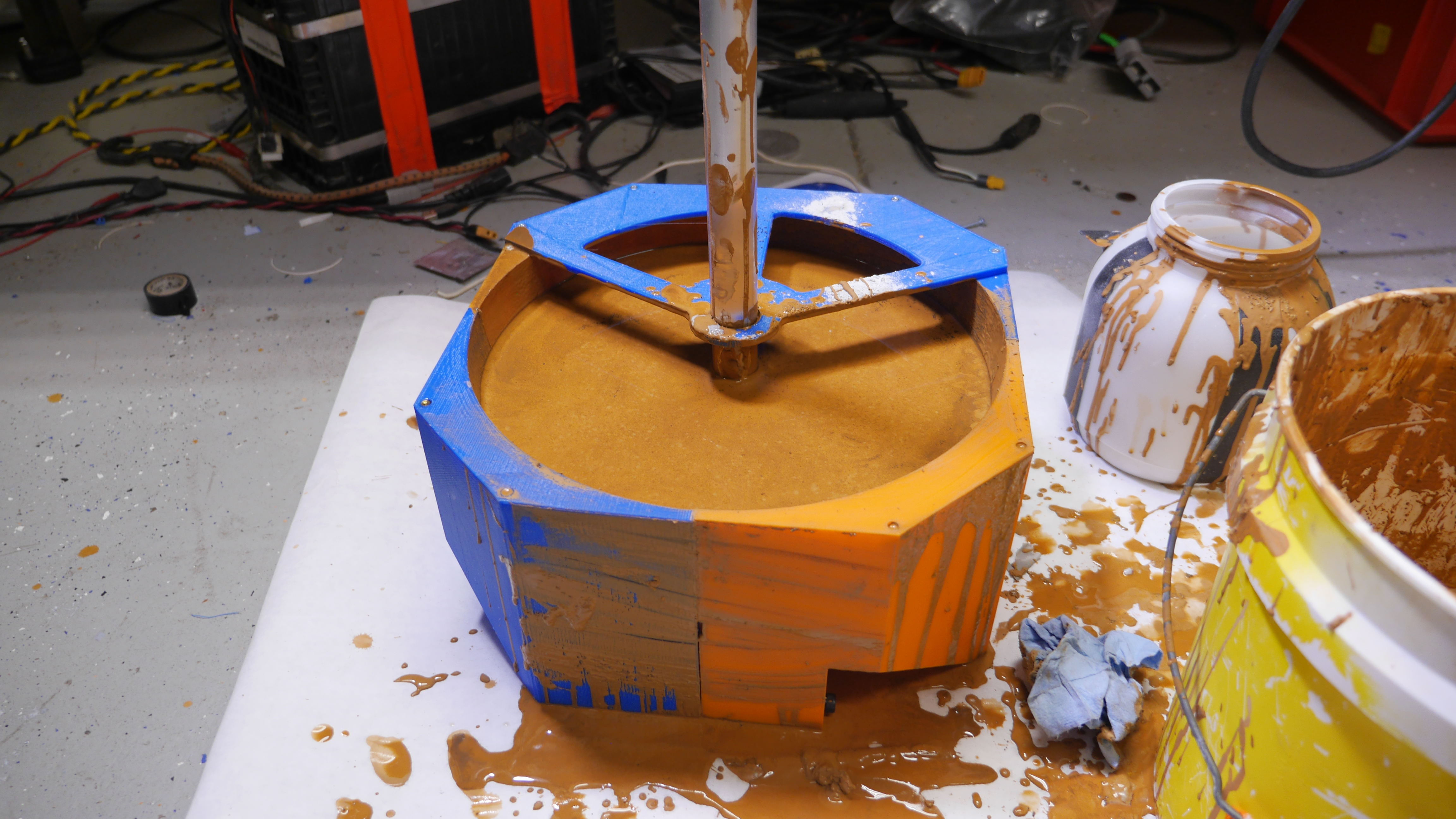
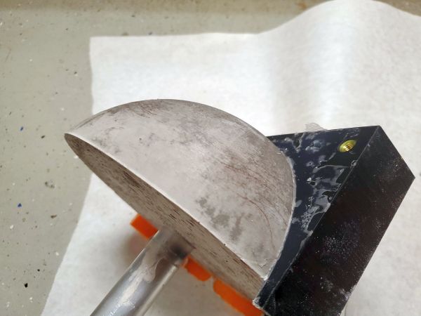
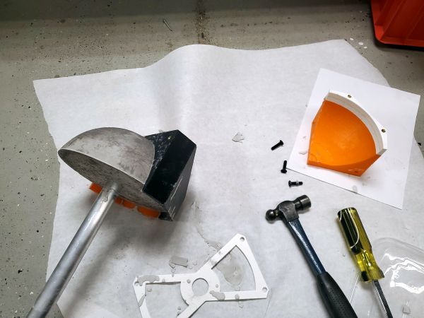
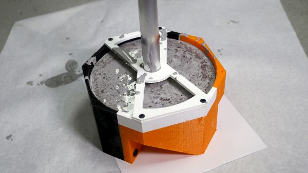
Initially I planned on just mixing in the mold, but i opted to mix up the concrete in a small 3 gallon bucket. This worked remarkably well. Due to the small batch size, I mixed with two layers of nitrile gloves, this worked better than a tool would have as you could feel out pockets of unmixed material. Because there was no aggregate the gloves held up during the mixing. I should however have used more layers of paper between the mold and the floor, the process is messy.

The mold did great, I couldnt really believe how easy this was. The haphazard self tapping screws worked out well too, they stuck out enough to interact with the concrete when I spun it around to aide in the mixing. After curing it was rigidly attached. To de-mold the first 'casting' i loosened the M6 screws and inserted a large flathead screwdriver between the seams. With a slight tap the mold detached from the concrete casting and we were off and ready to go. The surface finish was stellar. I was expecting bubbles or voids but it really came out great. I think the 'smeared on RTV' really made a difference on the surface quality as well as the de-molding. I did use a very small hammer to help detach the mold from the concrete. The only change to the mold i would make would be to add in a feature to pry against with the screwdriver to detach the mold pieces.
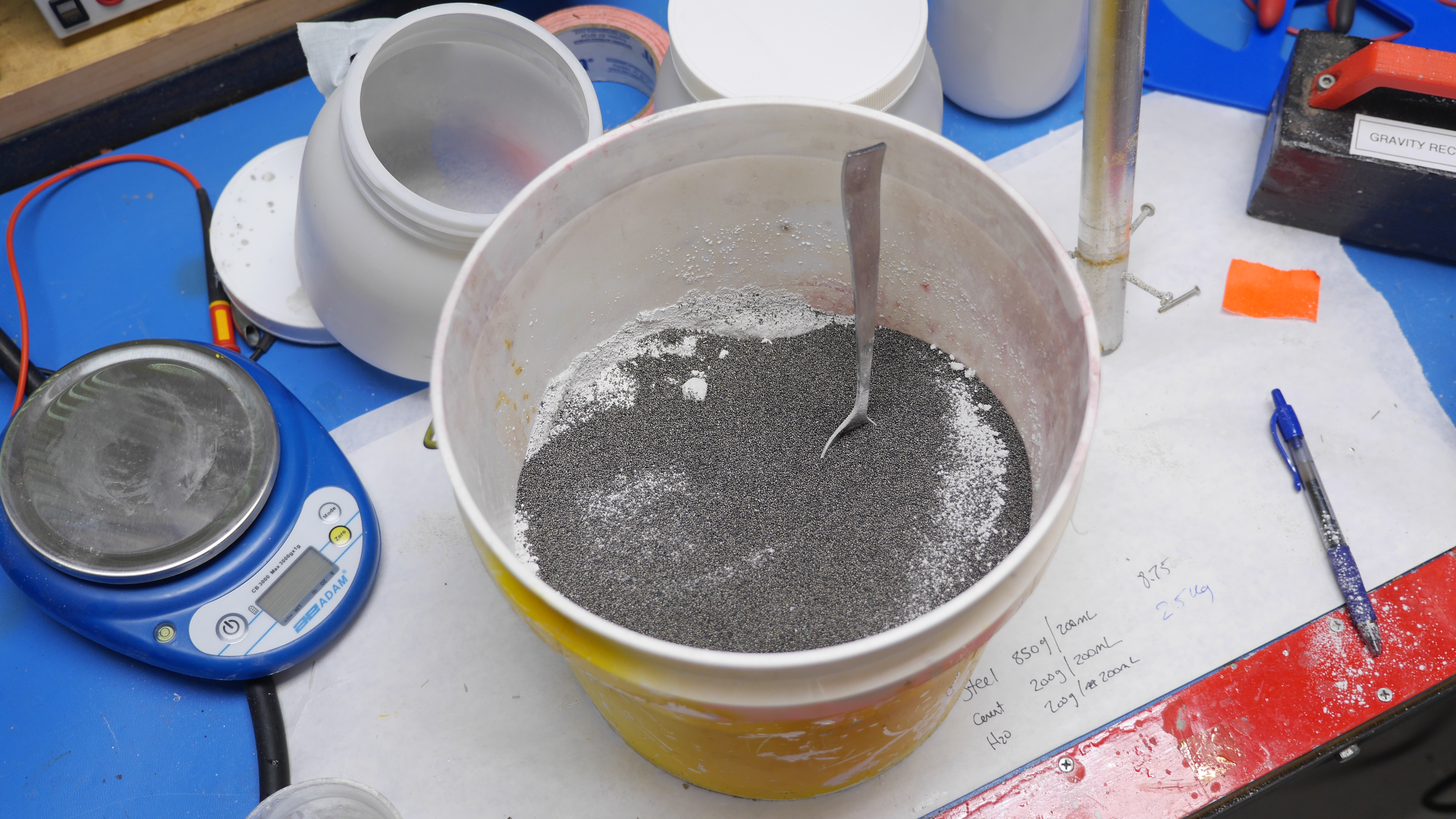
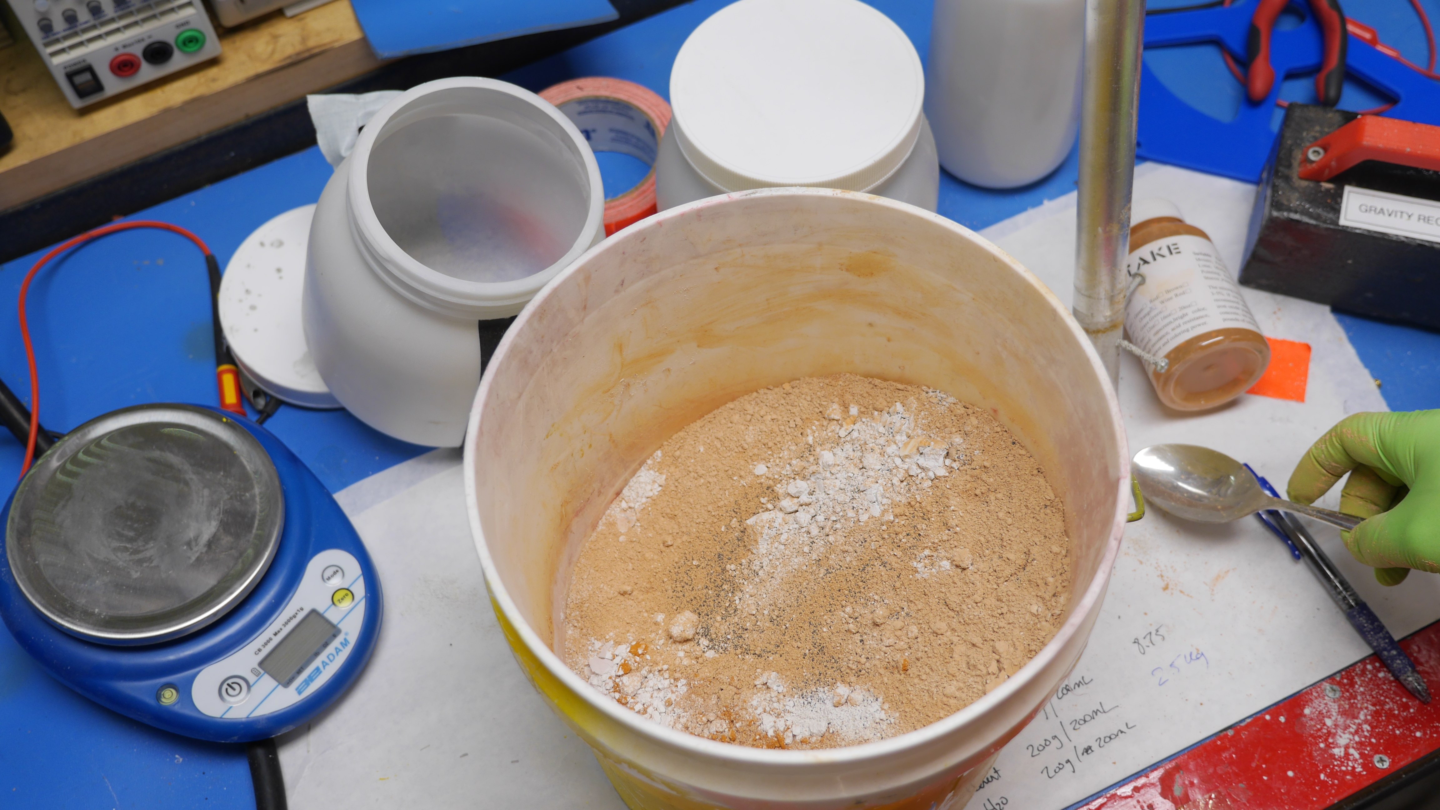
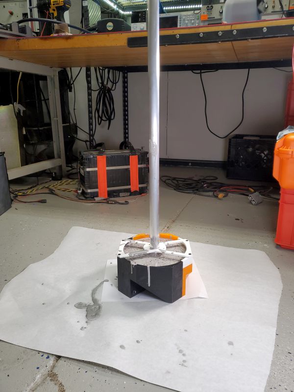
figure from paper figure from paper

Next up lets give a go at a steel-shot densified concrete pour, using 1-Part water 1-Part cement 1-Part water and 7 Parts steel shot by mass: I mixed this the same way as the first go, using a 3gal bucket and mixing by hand with gloves. Unfortunatley this started to go poorly, as the gloves started to tear with the steel shot. Things got worse as the steel shot is ~3.25 times denser than concrete so it immediatley stuck to the bottom. Finally the mixture seemed hyper-watery. I pushed on and poured it into the mold and waited. The steel shot that was present on the top flash rusted over due to the very wet mixture. I de-molded 12 hours later and found this: Shown below is the cement only and the densified cement.
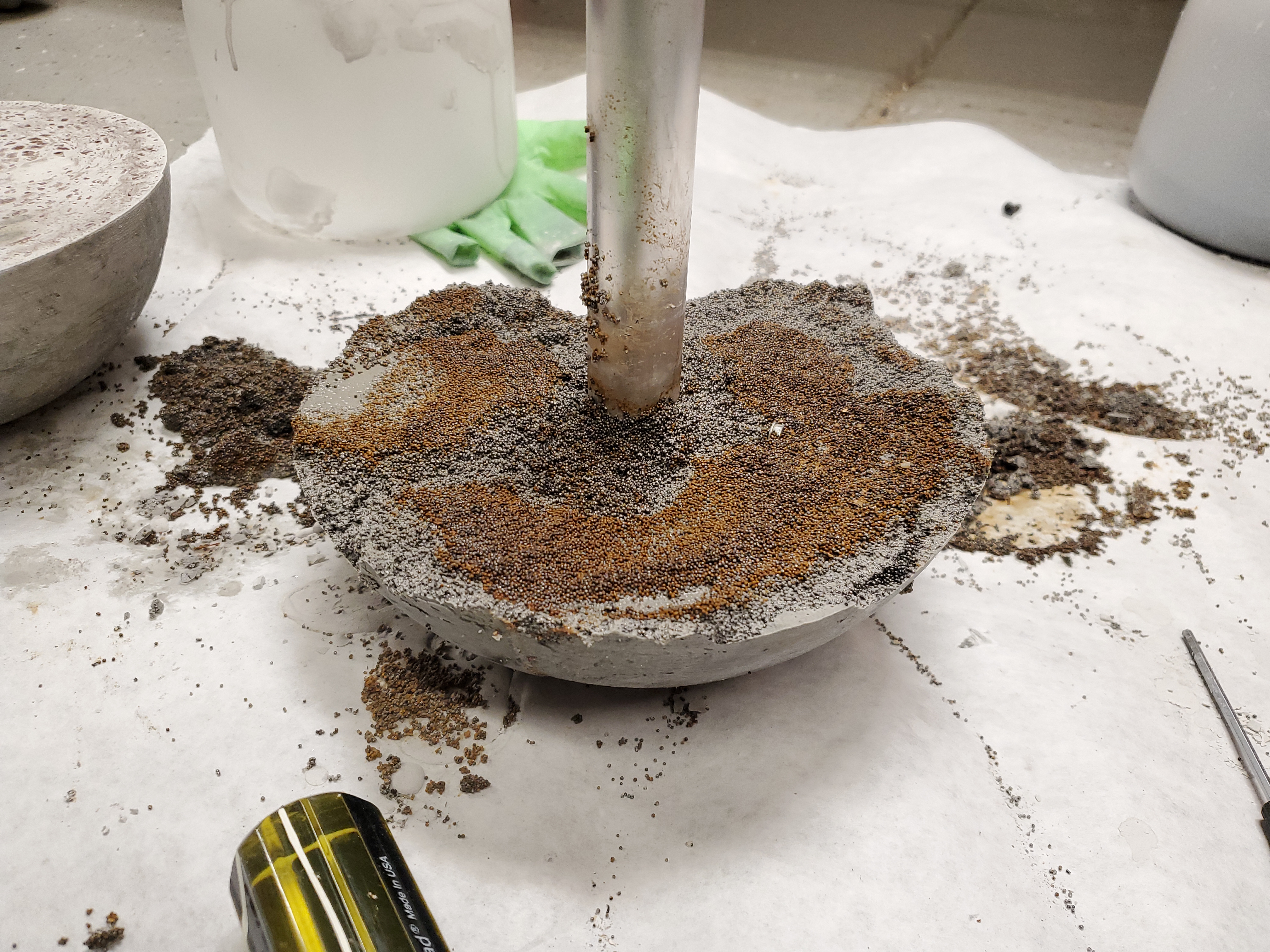
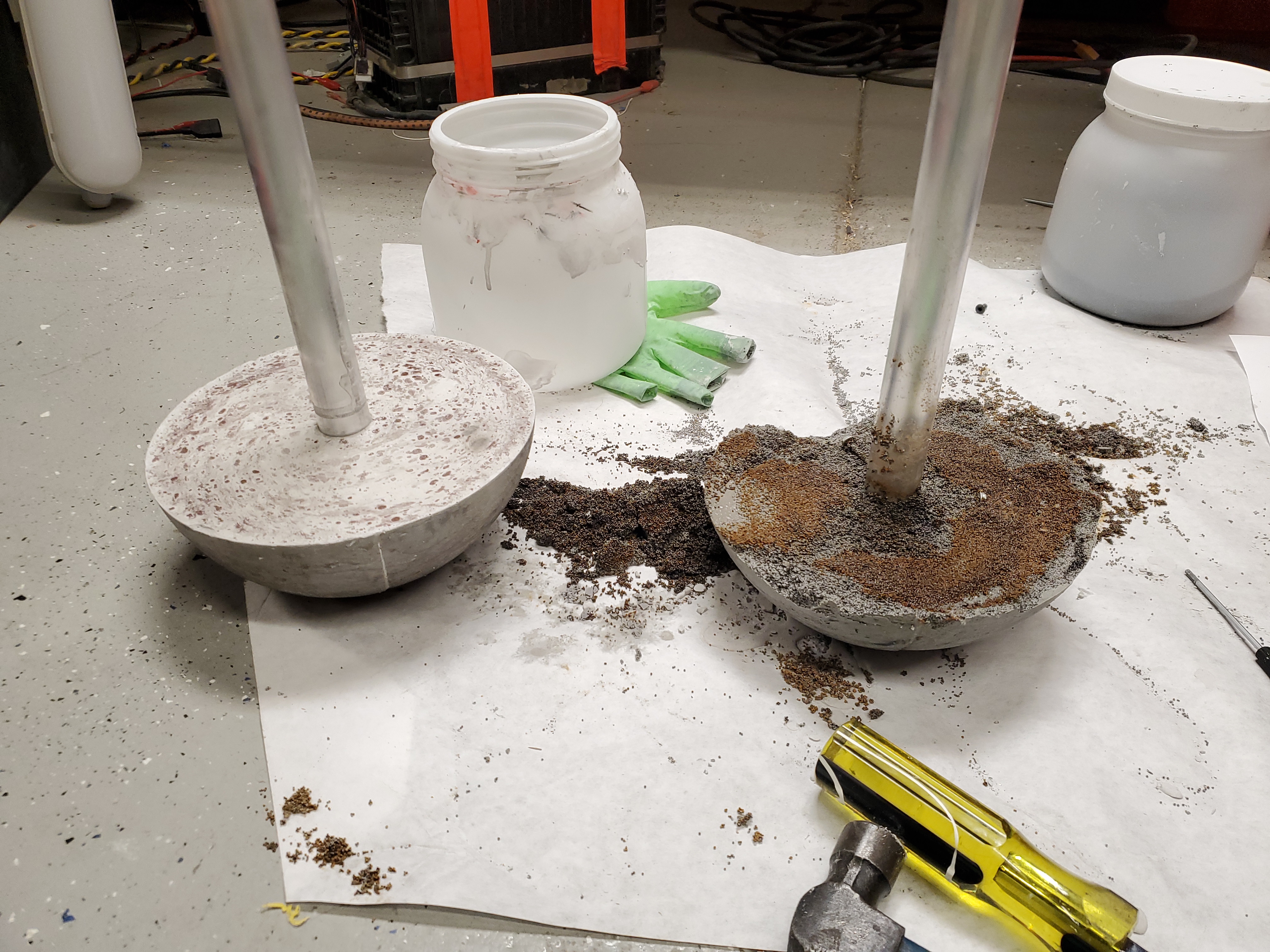
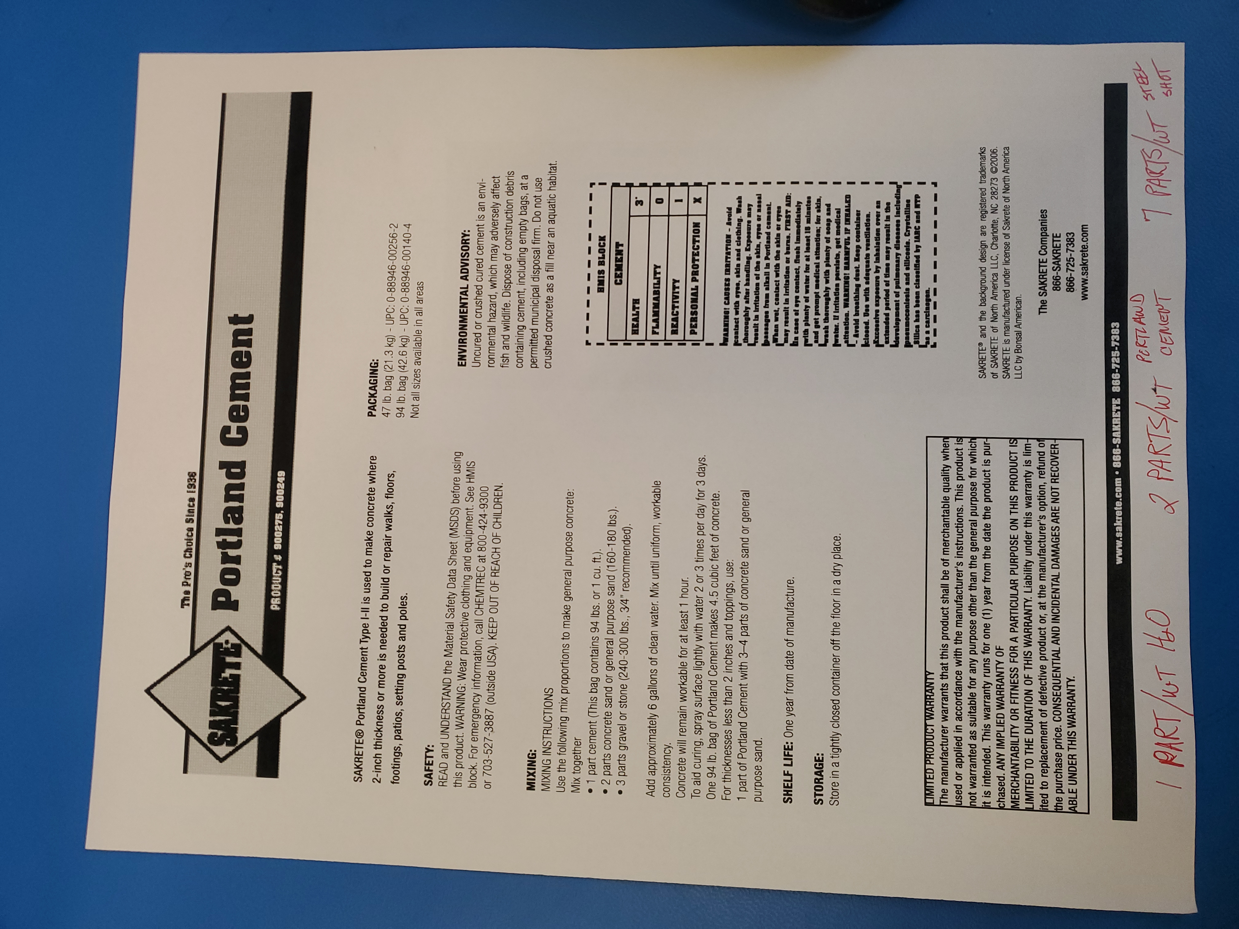
figure from paper figure from paper

It came out terrible! What went wrong?

The steel shot at the very top, exposed to the moist environment flash-rusted over and the concrete was comically crumbly. I was able to disassemble the casting with my bare hands. Something was awry here. As it turns out the recipe was wrong : /

I got an unfortunate update regarding the 'densiifed' concrete mixture. What is densified concrete? Its just using off-cast steel scraps to add mass to block gamma / to an extent neutron radiation. This is a common alternative to just using lead as its easy to make large semi-structural blocks, while nominally being cheaper than lead per unit density. It turns out the 'ideal' mixture for dense concrete by mass is actually 7:2 not 7:1. For reference the 'ideal' mixture is listed on the bottom of the page:

1 Part water
2 Parts Cement
7 Parts Steel shot

figure from paper

Initially I designed the mold around a 7:1 mixture of steel shot to cement not 7:2, so now the density is different. Lets re-calculate the mass and sort out the size required. After this lets print out a new mold to take into account the new 'densified cement' mixture. I did also somewhat learn from the first test that the mixture was mostly steel, and I should wait longer for it to 'set up' before pouring it into the mold. I also sorted out that i should get a legitimate mixing tool, even if it was a silicone spatula, the gloves were no longer up to the task of mixing. The last part of note, I did not really love the new 'asthetic' of the rusty steel, while i was not sure if that was going to persist with the correted recepie, I plotted a workaround, adding a coloring agent to the cement mixture. I purchased a 4oz container of orange concrete pigment so the cast part would at least have some redeeming coloring [link]. Excited to see how this is going to turn out.

One of my takeaways is to make a non-dense concrete mix for the top 1/4" of the mold to keep the top surface from flash rusting over. Either that or paint the thing to prevent large amounts of oxidization with concrete floor epoxy, that should bind fairly well.

Making the large mold

Just like last time, except larger. To print this out I used a Type A Machines Series 1 for the 'blue' parts and an UP! Box + for the orange parts. Each print is ~14 hours and chewed through a half-roll of dremel brand pla. I was fortunate to have two printers able to make parts simultaneously but it was still a fairly significant amount of print-time. I did end up adding a new feature to make it easier to pry the molds apart. Note that the parts are designed to not need support if printed in one direction, while the raft helps, there's no support for the remainder of the part.

Cura did not lie, these parts took a while. The print orientation shown first prints better as there's basically no overhang. The second variant is faster with the same quantity infill but the large flat area gets sad without support.

Fortunately the prints came out rather stellar. After removing the support material everything "just somehow lined up" even though parts were born on multiple machines. At this point we have a 6" radius half-sphere.

A copy of the STL for this 6" radius model is available here: [link]

Time to install a new set of thermal inserts. The top inserts got demoted to M3. I used the same technique as before, heat up a machine screw with a thermal insert installed, set the insert + screw and then re-use the screw after the insert cools off. There's eight top inserts total and only four are really required, due to the updated top jig.

Next up is the large M6 thermal inserts. Because these surfaces are face-seals, i opted to press the thermal insert in further than the face to make sure no 'elephants foot' protrudes and the face seal sits flat. Again there's only four of these holding the whole mold together.

Finally the whole thing is assembled, on the last part RTV is applied to both sides of the mold and the long M6 screws mesh everything together. Because the infill is not super high I did not crank down on the bolts too much, but everything ended up lining up fairly well. I only applied RTV to the mold-facing seam to help prevent it being difficult to disassemble, only really the round part of the mold needs sealing anyway. These new mold segments do have a 'pry' area for a screwdriver which should make disassembly easier.

The last bit was to finish up the new vertical mast holder. Unfortunately now that the mold is enormous, its difficult to print out the same design as before, but i came up with a solution, just have the mount grab two sides nearby and leave the remaining side fully open so  cement pours are easier. 30% infill later and we have a 3d printed post holder that's removable. The infill is higher than I'd normally go, but should provide a firm connection for holding the 1" diameter aluminum tube while the cement sets. This is very much one of those times where a laser-cutter and a piece of acrylic would have been significantly faster, but at the moment I do not have a CO2 gadget. Either way 2 hours later and i have a large 2D part. Unfortunately as this is very large it does end up restricting which printers can print it. Nominally its possible to split this up into two parts and glue them together to have the same effect.

We need to get a better idea on the volume and weight.

We know the new ratios are by weight. We do however have a 'volume'  to match up to these weights so we make an appropriate amount of mix. My large scale is a bit missing, so I used a 3KG max scale to get an understanding of the weight per ml. We learn the weights and volumes:

Steel Shot: 850g / 200ml
Cement Powder: 200g / 200ml
Water: 200g / 200ml

So for this pour I opted for 8.75KG of steel shot, 2.5kg of cement powder, 1.25 kg of water as the basic mixture. This should be right but it turned out a bit too watery, as it was likely the 'cement' used in the recipe was a bit different than the hyper-fast cure stuff i was using. As a result i added 1kg of extra cement powder, and 500g of orange pigment.

With everything massed-out, It was time to mix up the dry parts. The steel and powdered cement was mixed to be somewhat homogeneous. Given how the steel is significantly denser its hard to keep everything well mixed. I added in the entire jar of 'orange cement pigment' and its shown to the right. The 'orange' concrete pigment was very rust colored. I was hoping for a loud bright fluorescent orange instead of a rust color but it is a first test part.

figure from paper figure from paper

With the mixture somewhat mixed (ahem I was using a steel  spoon to mix this as the steel shot is terrible to get mixed correctly) The spoon ended up falling into the mold but was eventually fished out. This process was remarkably messy.  The vertical rod was re-oriented after the mix was poured and re leveled. One of the parts that I 2did not initially think of was how any of the other open threaded insert holes got back filled with cement goop, so I would end up using the four in-use ones going forward.

The transition from goopy liquid to solid was remarkably fast, almost like plaster?

figure from paper figure from paper

Using a the mystery cement also resulted in some mysterious behavior. While the cement did not 'expand' as indicated on the paper brochure, it did get warm quickly. Nothing too hot to note but definatley warm to the touch. The highest I saw on the thermal camera was ~40C, which is fortunately no where near the plastic transition of PLA. I was a bit impatient on waiting for it to fully setup, after about and hour after the pour I started prying apart the mold. Like last time it came apart fairly easily. I was somewhat expecting to see the bottom as just a conglomeration of steel and the top just plain cement, but it appears the quick-set nature of the cement ended up curing before the density differential had time to take effect.

figure from paper figure from paper

I made a quick 1/4-20 adapter to sit on the end of the pole and attached an off-brand Bogen quick release mount. The first 'tripod' test with an actual payload, in this case a small light with a Bogen quick release mount attached was ready to roll. While this looks incredibly goofy, it, well it is. Its fun to play with but nominally *it just works*. This is very much a test / prototype but I'm really surprised how well this worked right off the bat. The weeble period, like a pendulum, is heavily dependent on the mass of the object on the end, along with its position. Also apologies for the mess, it was quite a zoo. This should work for a camera, a camera light or even a teleprompter. Without a handle it's fairly awkward, but that's only a quick 3d print away.

How heavy did the casting end up being?

Initially the plan was 28 lbs, however due to trying to compensate for the visibly 'wet' mix, it ended up closer to 31lbs. The displayed mass included the light-fixture + battery, or the mass of the total system. The bike scale, documented here, was the most accurate 'large scale' I had at the lab. While the edges of the top of the casting are likely to crack over time, they were fairly sturdy even without glass-fiber reinforcement. For future casting I might opt for a different concrete pigment, try using normal commercially available cement mix from the present day, and also sort out a way to use steel plate internally as a counterweight, and normal cement as a binder. Pouring / mixing steel shot was unpleasant at best, it was very difficult to get it to mix well with the fine cement powder and

figure from paper figure from paper

This actually works fairly well as a tripod. Adding a mount for manfroto quick release on the top worked surprisingly well, the light fixtures did not end up rocketing off into space, and camera lights ended up staying attached.

Have you noticed that there are no advertisements or ridiculous pop ups?

No cookie banner or newsletter?

I'm trying to make a better web, feel free to support it.


Want More?

Here's a behind the scenes look at my work space and some of the images that did not make the cut to be included in the write-up:


`

If you have questions or comments, ask below or send an email


Post your comments!

Comment Box loading