Dane Kouttron
Project Started: 05/2017 Reformatted: 01/2024


Genome sequencers have cameras?454 lifesciences / Roche recently discontinued [link] the FLX series of genome seuencer. These contraptions are ~5-6 years old and use a process called pyro-sequencing to sequence DNA fragments. Pyro-sequencing results in light being emitted in presence or absence of a sequential associated nucleic acid based upon which a sensitive camera looks for photon emissions and uses that data to generate sequences from DNA fragments. More of how this happens is included below. The discontinued machines are similar to a Polaroid camera, after the film is no longer manufactured, they dont really do anything. Its uncertain if Roche will have a 3rd party make equivalent reagents available. Given that the sequencer will not 'sequence' anything without reagents, why not get the camera up and running and use it for, astro-photography, particle detectors or charged particle imagers. Tune in below for more! 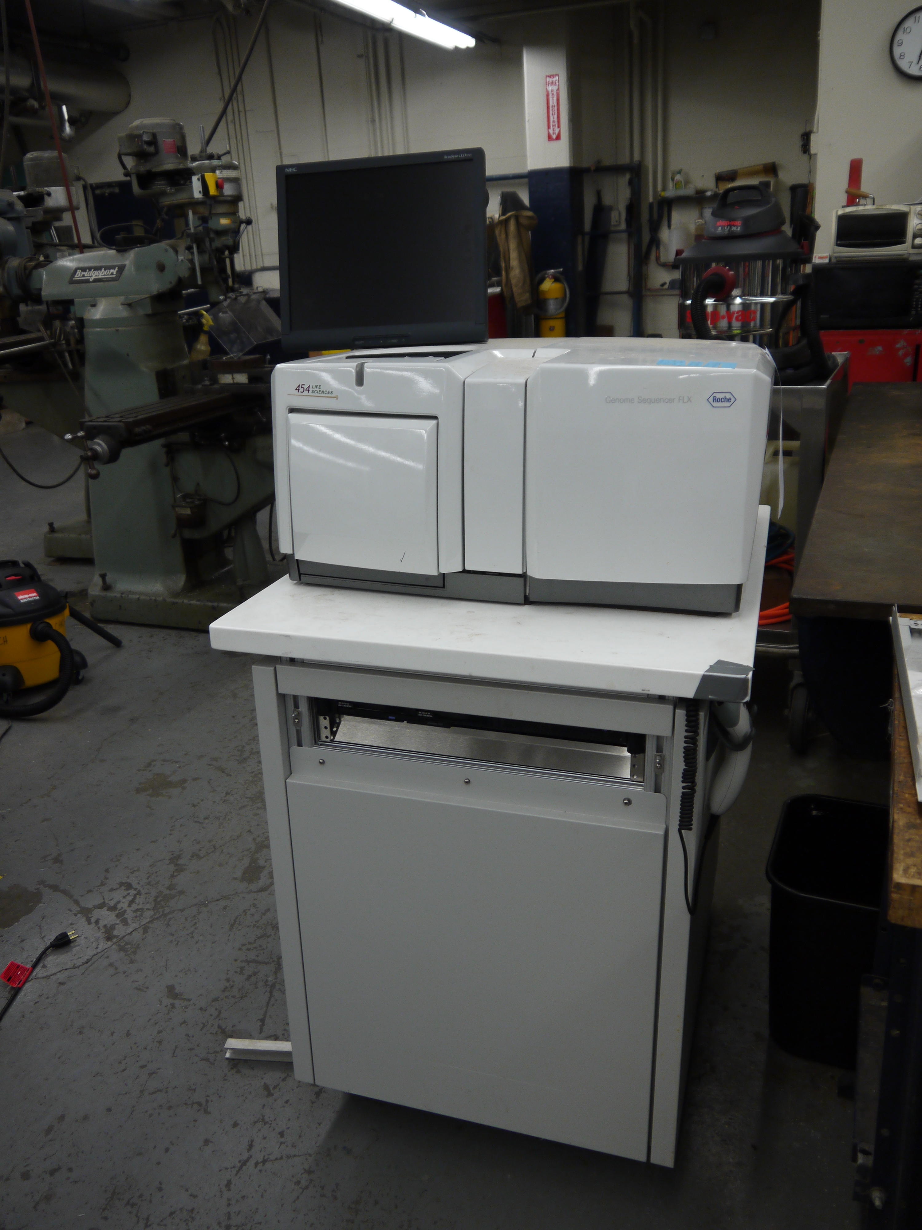
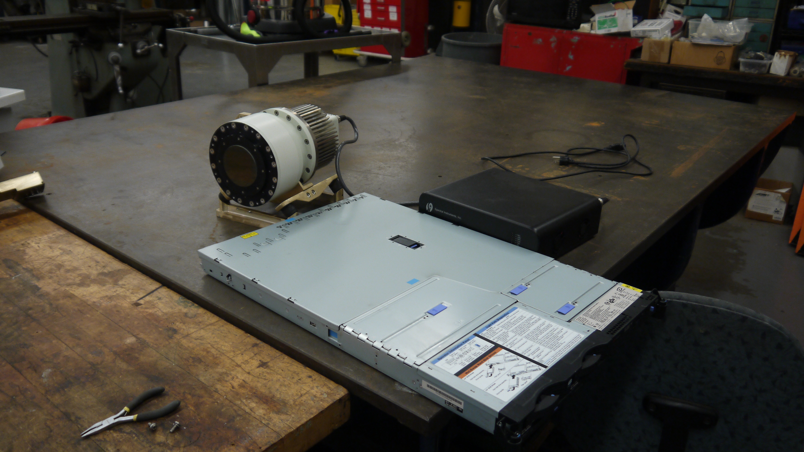
From the front view is the 1U PC that interfaces to the 454 sequencer. The 1U computer is an IBM X-Series 336 machine [link to series User Manual]. The ups is this thing [link],note APC re-uses part numbers, which is quite infuriating, the modern smart-ups 2200 is quite a different beast. 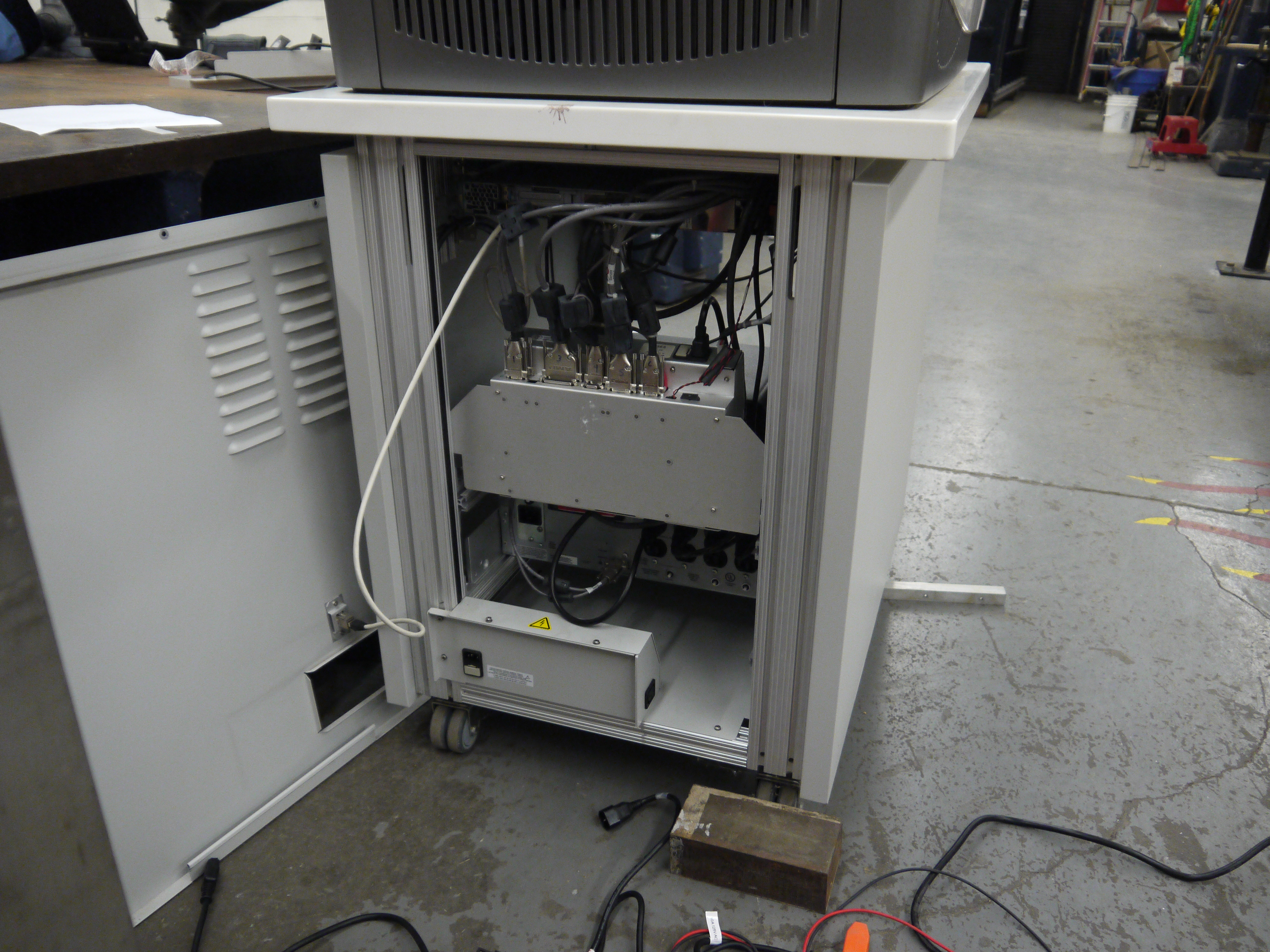
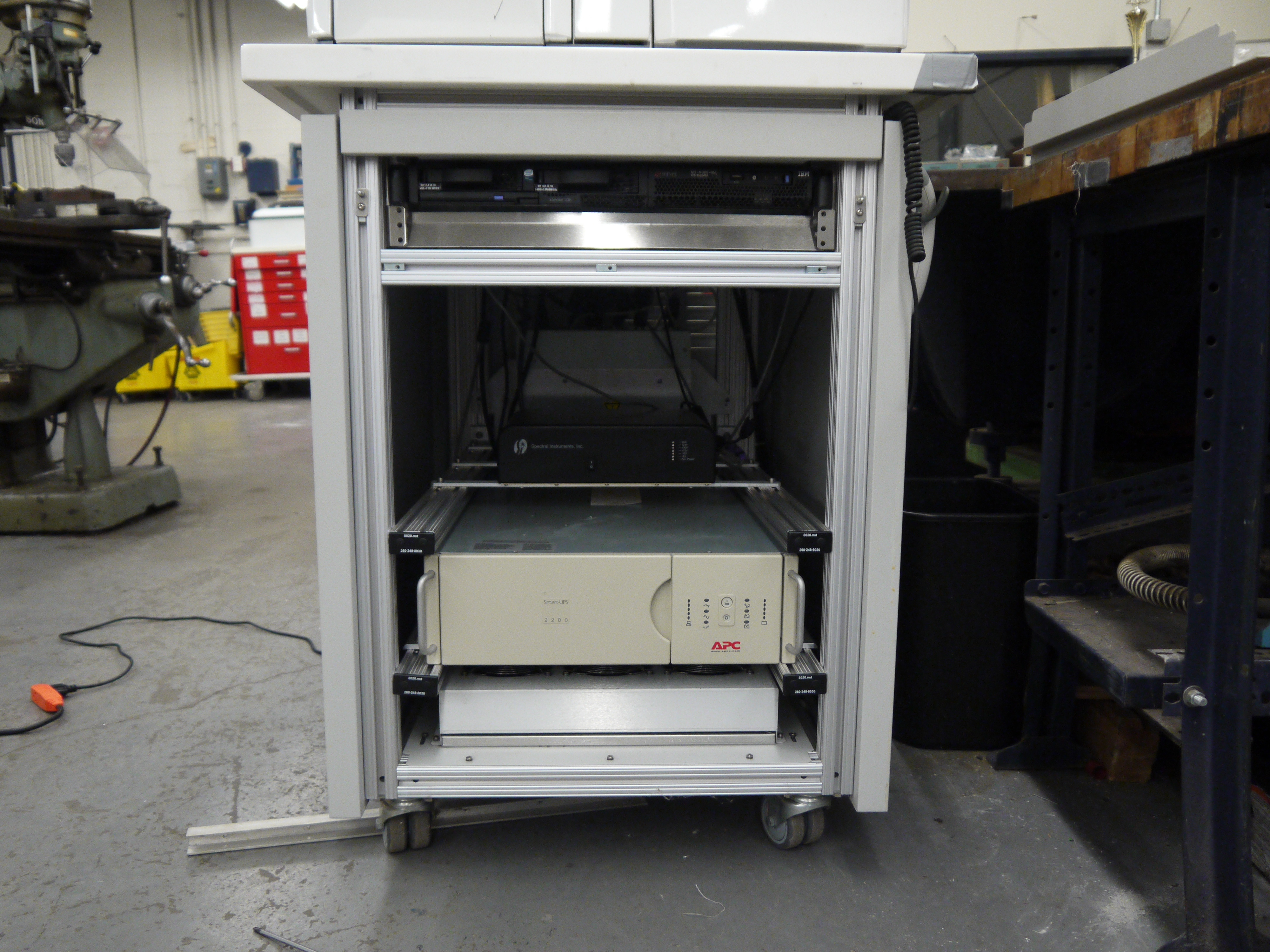
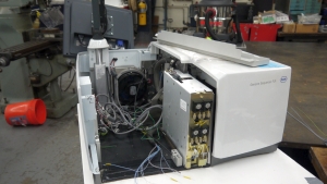
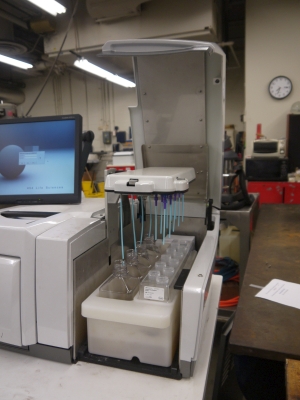
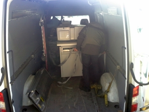
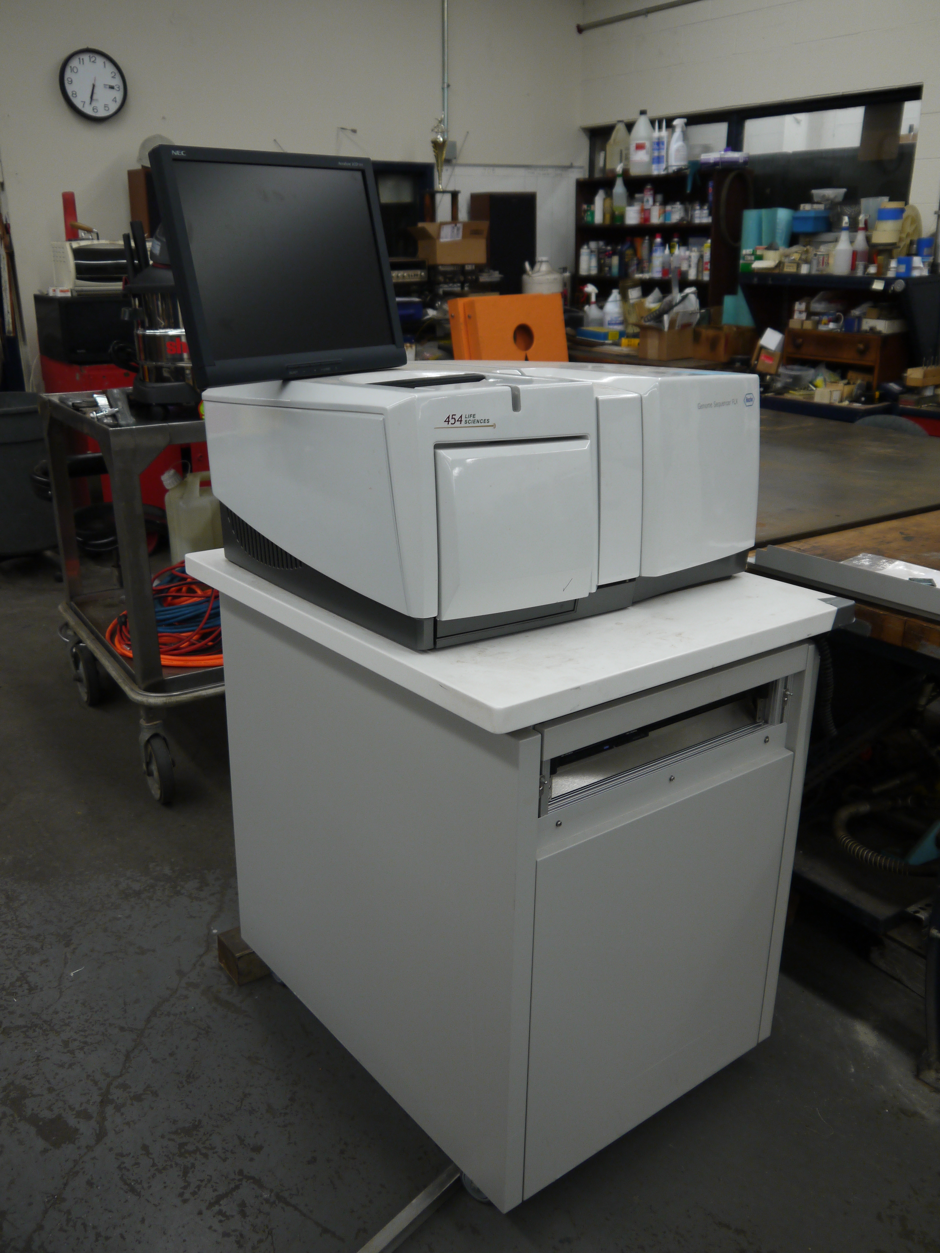
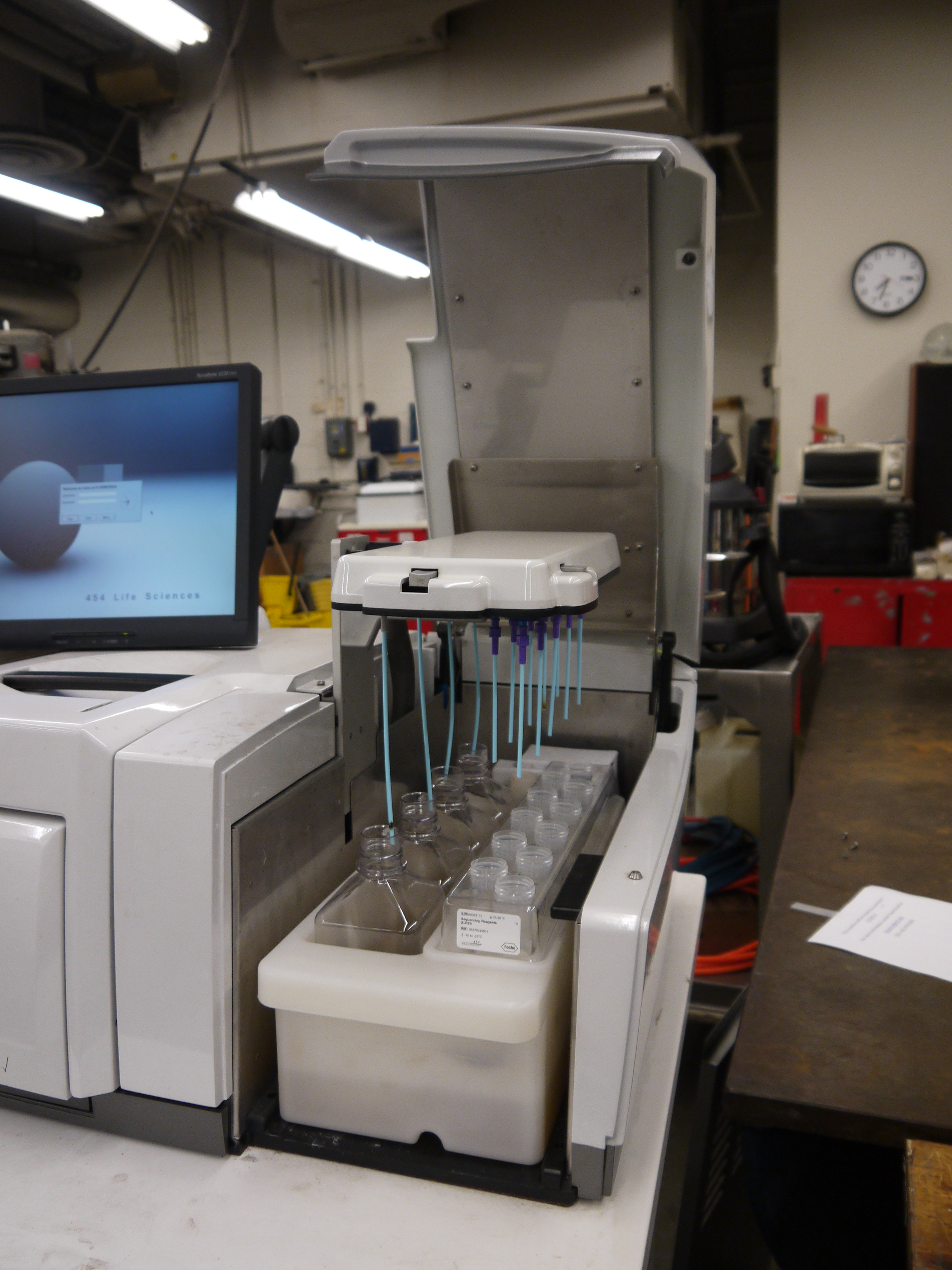
Pre-Disassembly: Firing up the Sequencer to see what worksThe sequencer itself is built like a tank, and weighs accordingly. The cart that supports the sequencer itself is mostly empty, at the base is a large APC Smart-Ups 2200. The genome sequencer (top shiny bit) is itself bolted to the top of the cart surface, which is some kind of lab-surface material. The whole setup sits on four rollers which are surprisingly good. It weighs in excess of 350 lbs (estimated from moving it around). Disassembly occurred on 12/29/2016, was rather quiet on campus.
From the front view is the 1U PC that interfaces to the 454 sequencer. The 1U computer is an IBM X-Series 336 machine [link to series User Manual]. The ups is this thing [link], note APC re-uses part numbers, which is quite infuriating, the modern smart-ups 2200 is quite a different beast.
When I plugged in the 454 sequencer to 120vac mains power, nothing happened. There is a master-switch along the right side of the machine, but alas no response. I checked the in-line fuses in the main outlet and both checked out. As it turned out the in-line mains filter had failed open circuit. Kinda bizarre, but could explain why this was put out to pasture. 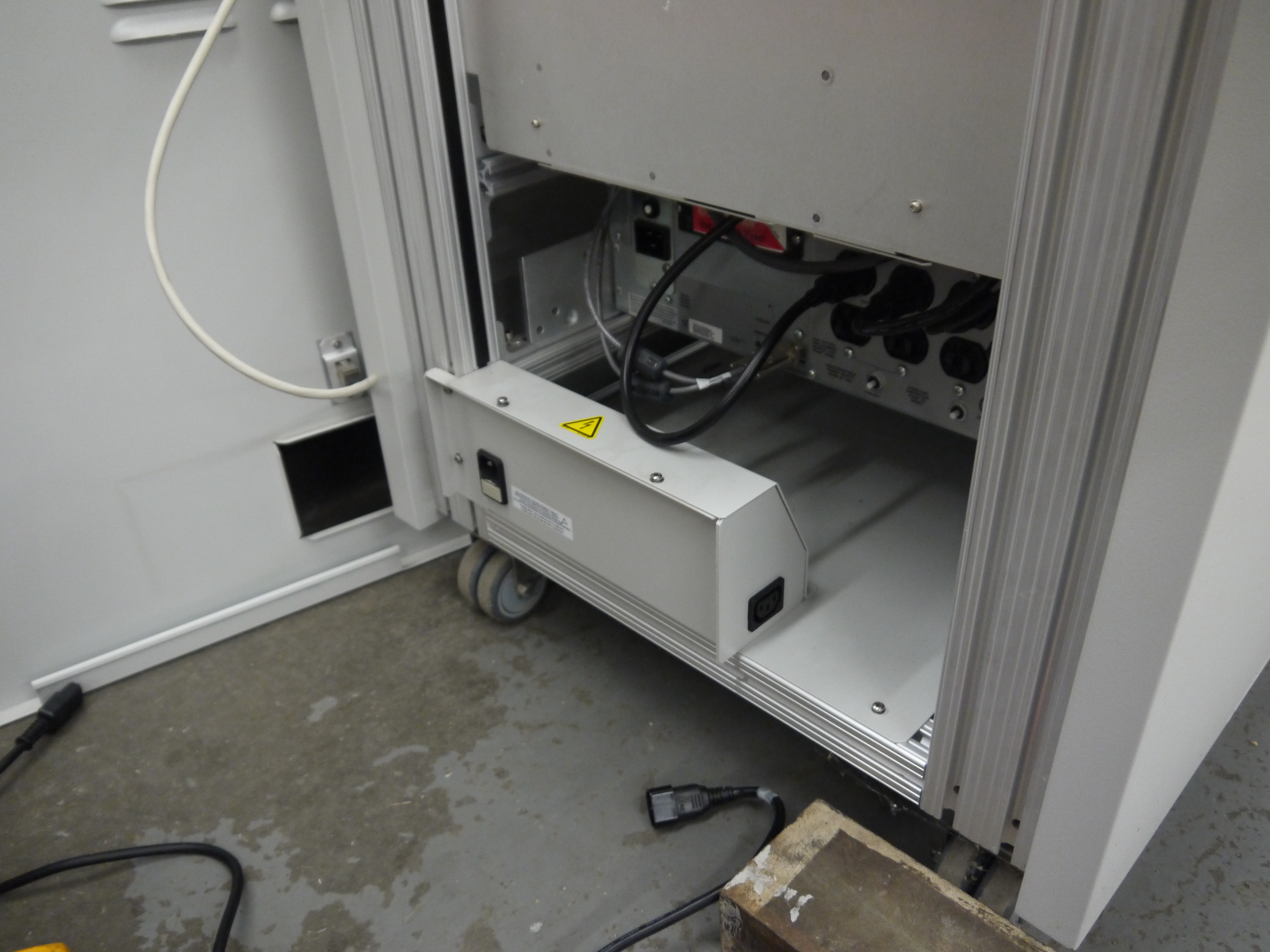

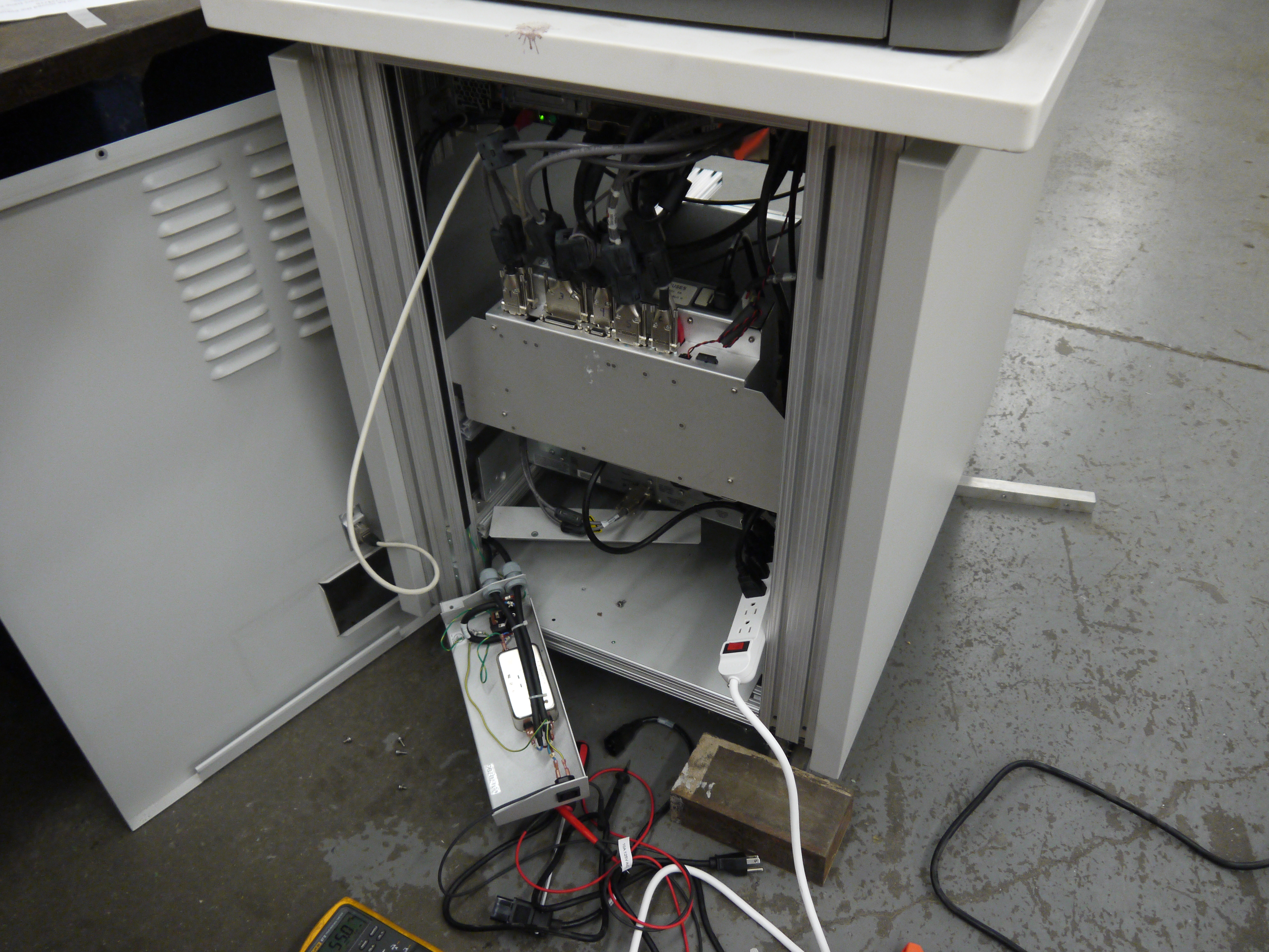
After meddling a bit and then getting impatient, I used a power-strip and fed all the internal hardware from a single strip instead, everything woke up from its slumber and the couple dozen watts of cooling fans fired up. I will mention that, even though I was in a machine shop with a fairly noisy overhead ventilation system, the fans and air cooling in the 454 sequencer were quite loud. The biggest culprit is the IBM server, second up is a 24v blower connected to the imaging camera. 
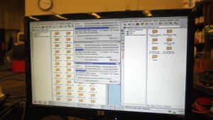
Login Details:After the machine ran through all of its startup preperations, a 454 Life Sciences prompt was displayed, requesting login information. I did a bit of hunting through every manual I could find for this machine and found a reference to the default login being ' adminrig ' for both user / password. Fortunately for this machine, that had not been changed. And lo it awoke, and after a bit of struggling came up to the main desktop 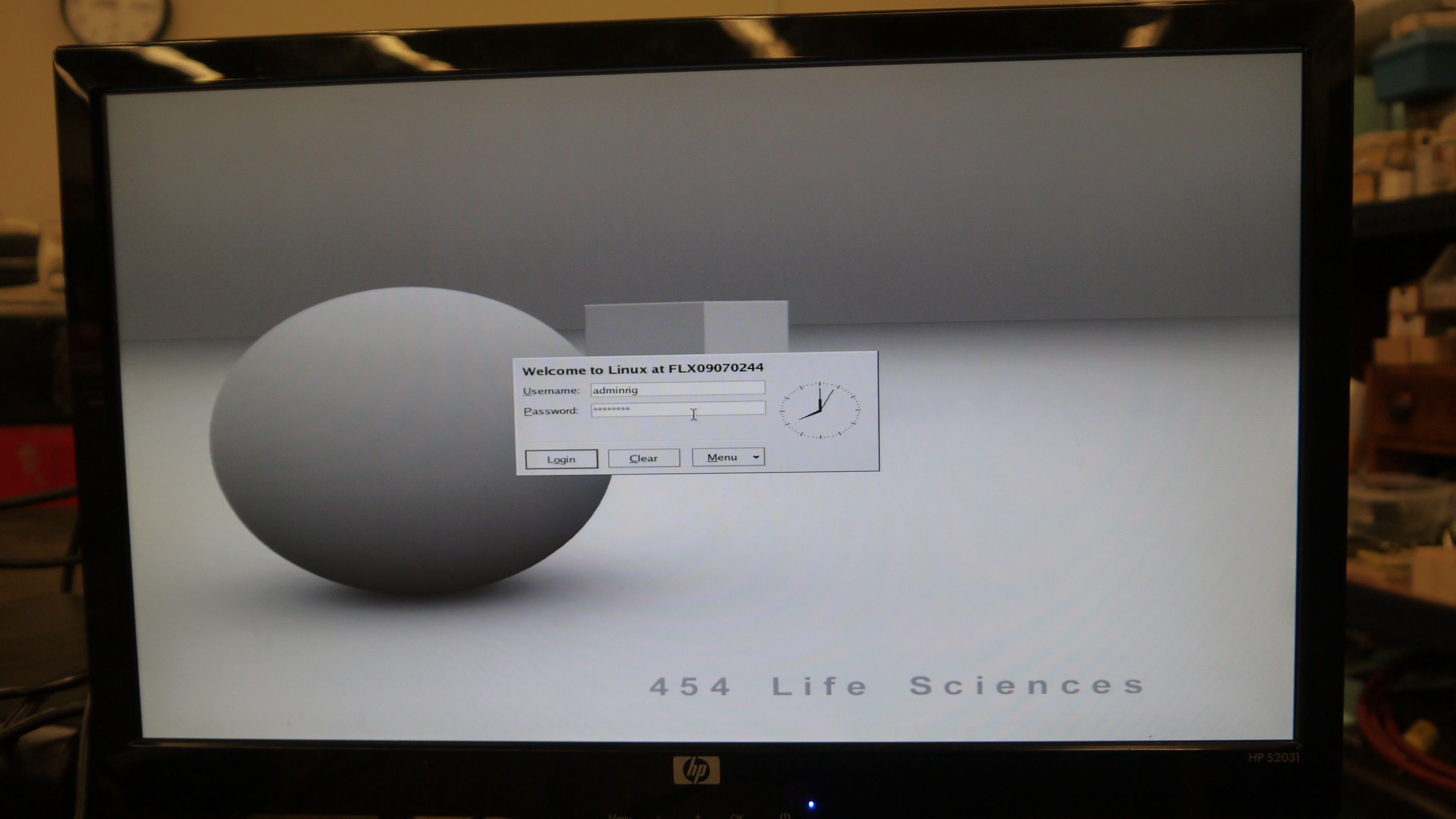

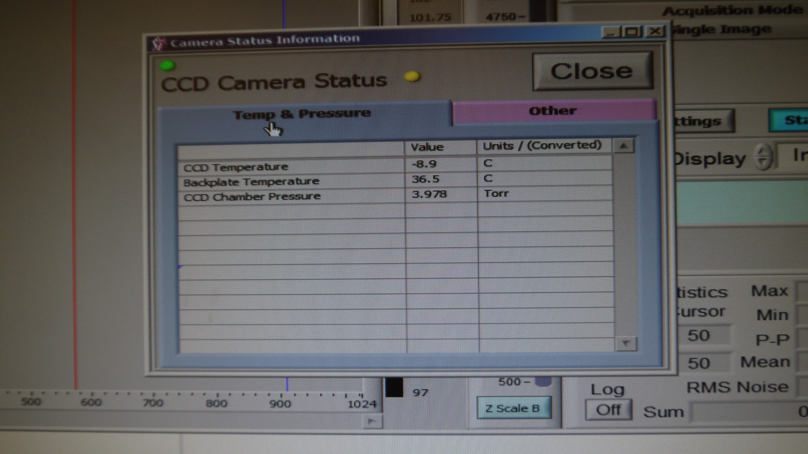
The main control software is accessible on the desktop, and some more prodding and poking is required to get it to fully fire up the camera, so far I've only been successful at requesting the instrument to start, and looking at its debug page to determine if the camera was cooling down properly. I didnt find the instrument software manual until later on, so I guessed at buttons, which didnt really lead anywhere. 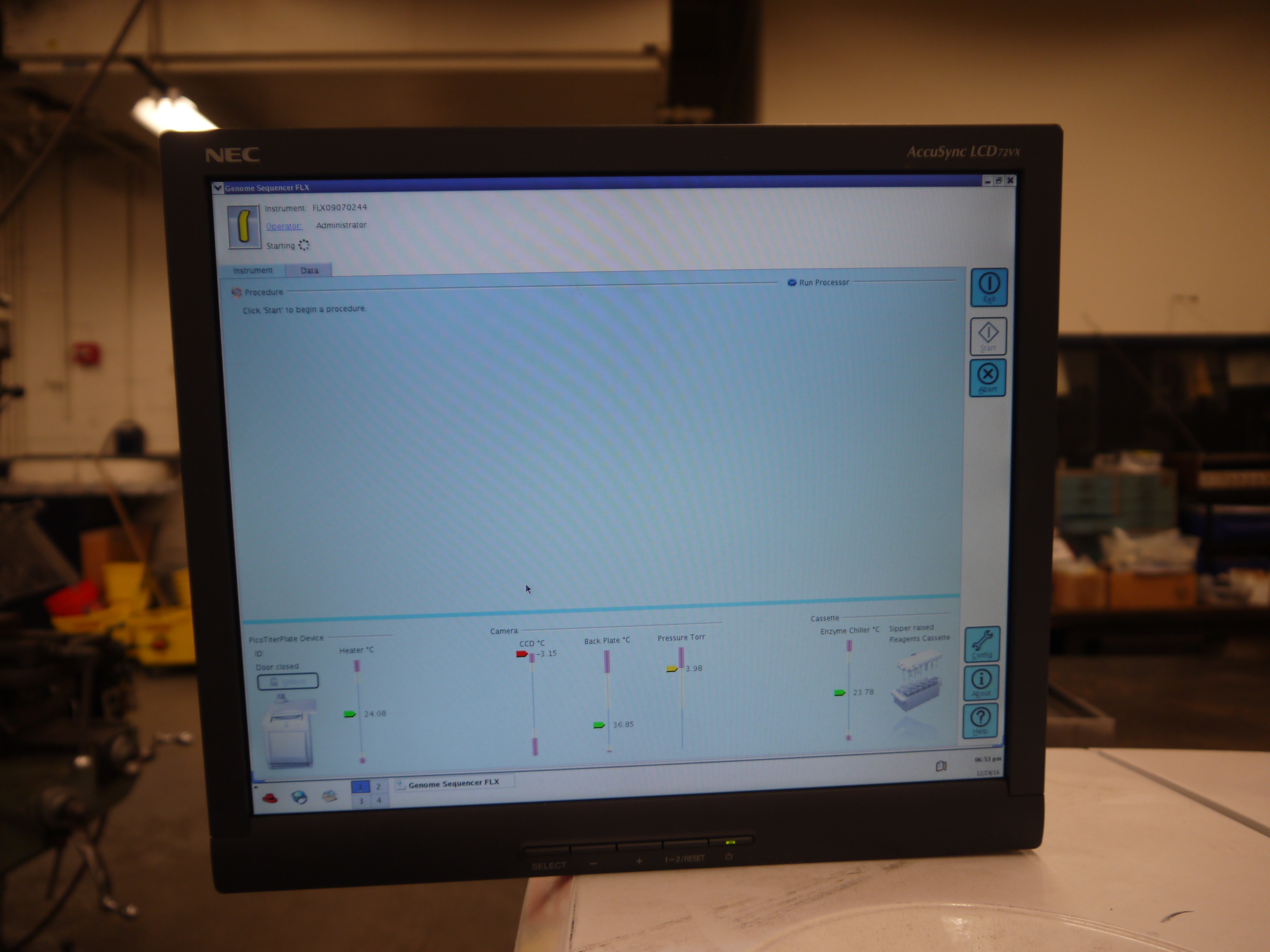

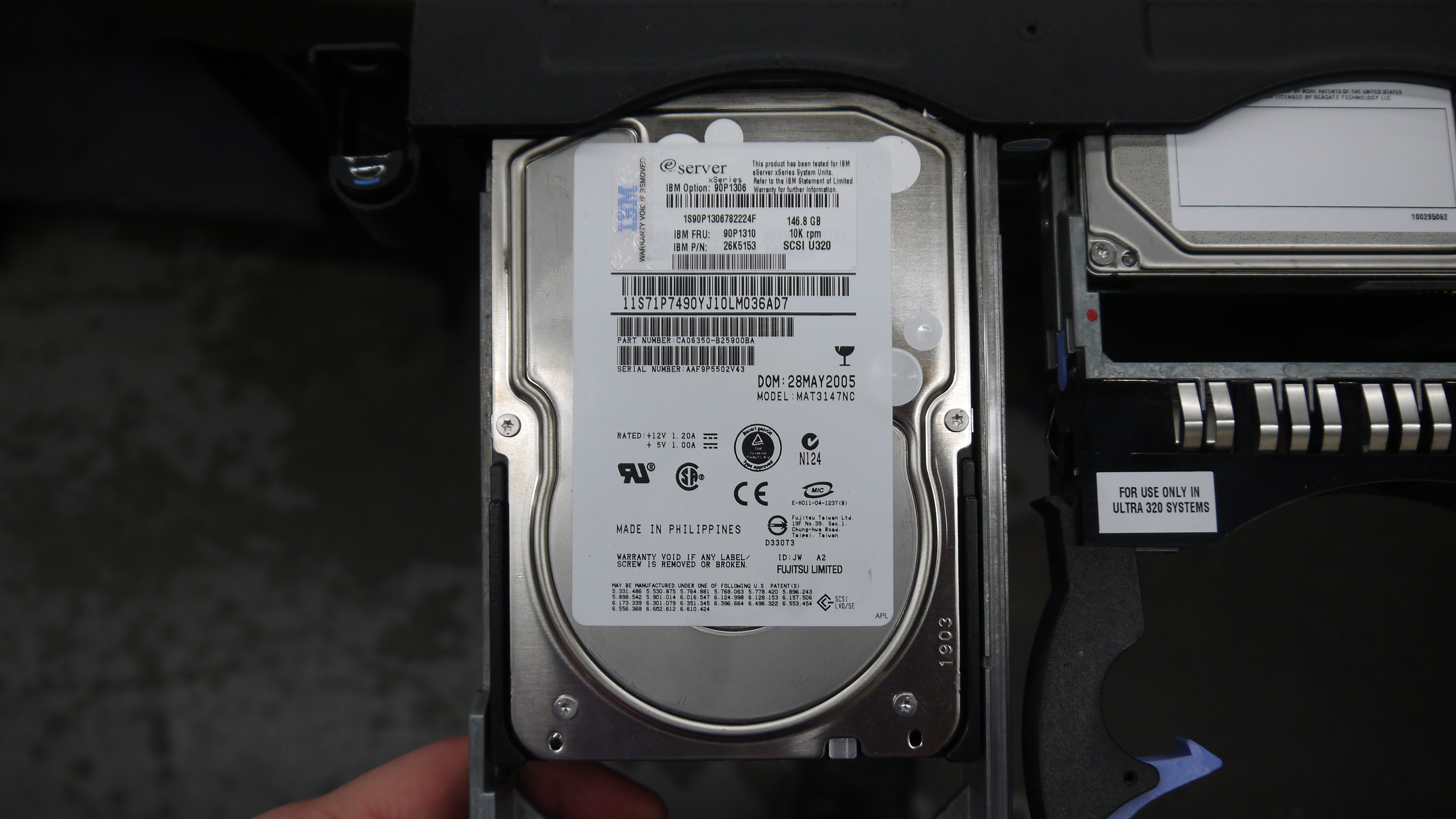
After a bit of attempting a few things to find debug interfaces to the camera directly, I copied anything that looked interesting to an external drive to search through on a faster machine. I will note that the IBM box was about a decade old at this point and the two spinning discs were the byzantine fast swap SCSI drives. 
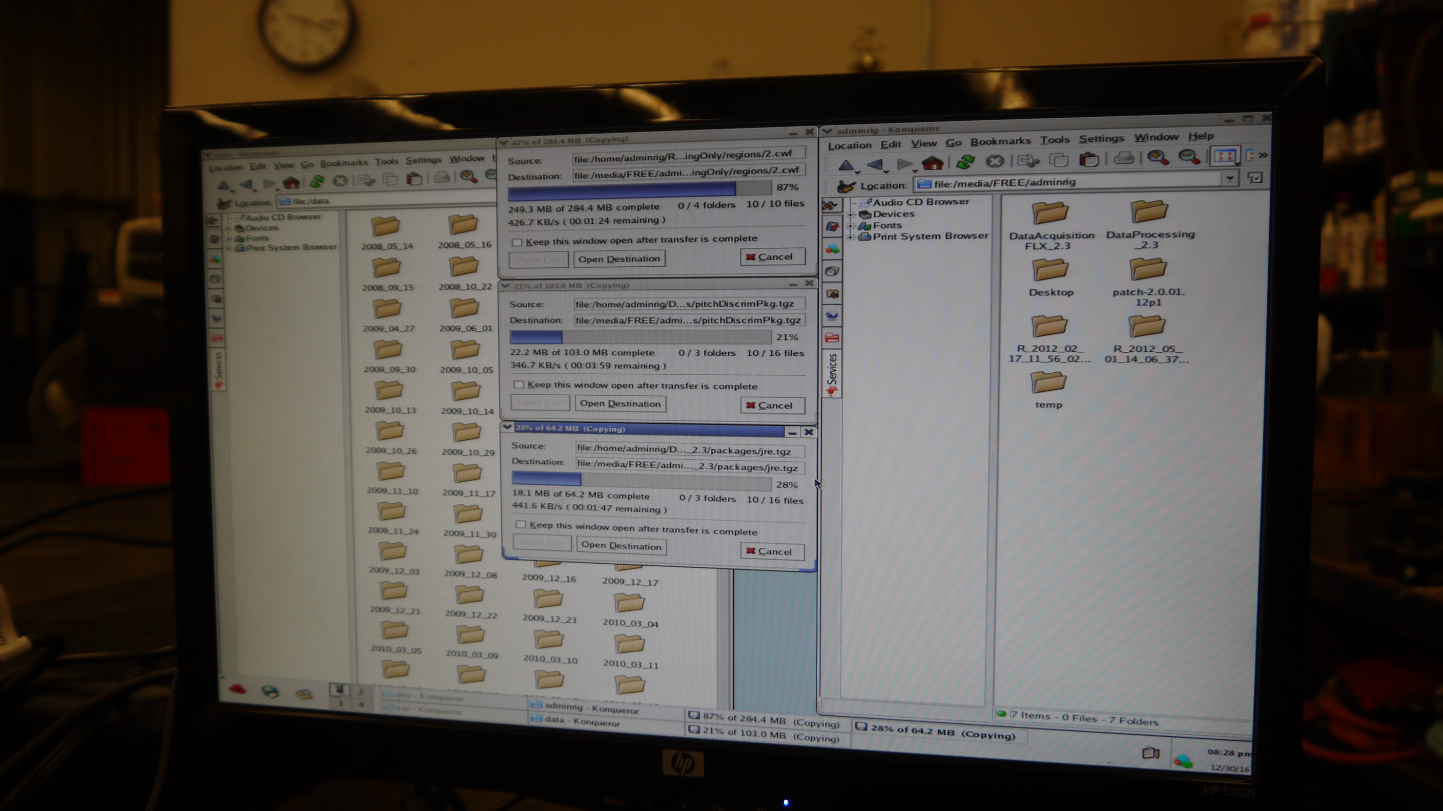
Drive cloningSo for whatever reason, the onboad ports on this IBM board for SATA were unusable, as in, the bios did not support the use of media connected, nor could it pickup a good drive. Whats bizarre is this same IBM machine came with the option of hot-swap sata instead of hot-swap SCSI. I attempted to clone one of the drives to a larger SSD, but alas, it would be hella slow over USB2.0, so i opted to copy off as much as possible manually. 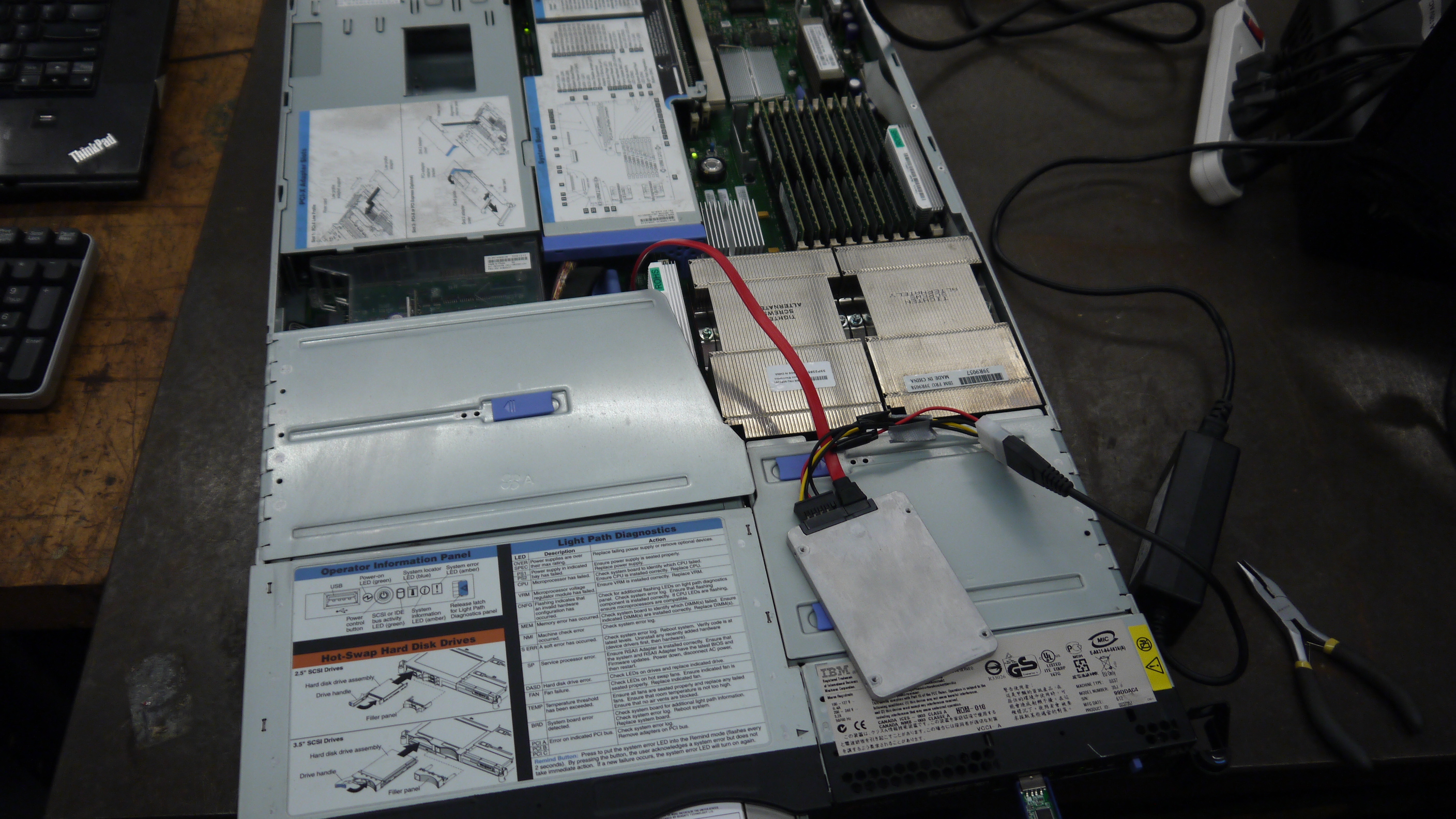
Sequencer Theory of operationOk, lets do some homework. How the heck does this thing even work, and why does it need such a fancy camera? Starting at the owners manual [local copy] there's a quick break-down of what is where in the machine, which is mighty useful when going through the system tear down. If you split the instrument down the center, everything to the right of the unit is effectively chemical storage and handling [fluidics subsystem], and everything to the left is reaction and imaging [optics subsystem]. The computer and associated control hardware are all hiding below the instrument and controlled over (for the most part) dsub terminated cables. 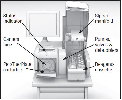
How does a camera and a bunch of plumbing construct a genome sequence? How large is a gene sequence?EXCELLENT QUESTION: First off, here's some reference files, local copy in case direct link to manufacturer sites change.
* GLS FLX Owners manual for an upgraded version of this machine [link] 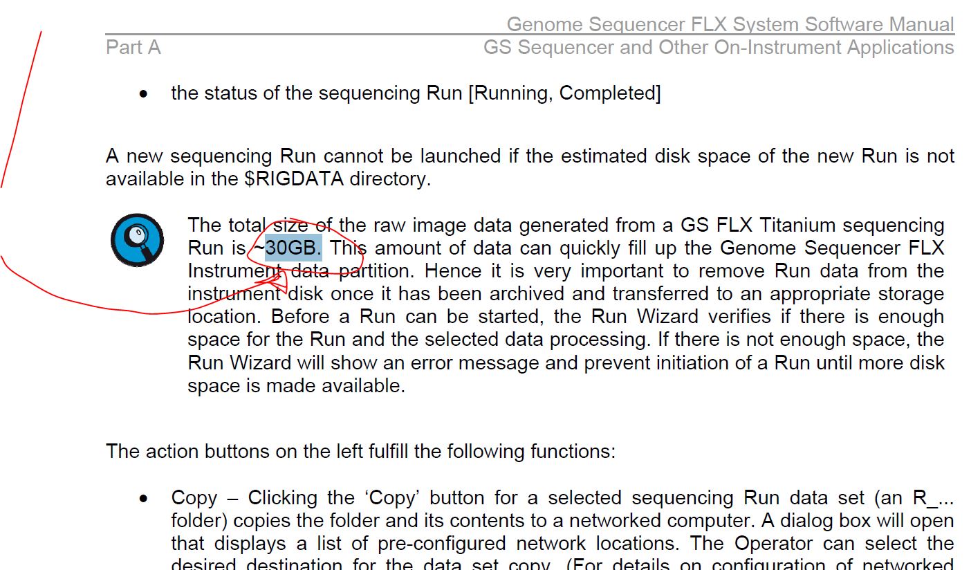
Step 1:
Start with a genomic sample, fragment it into smaller chunks, or segmented samples. There's a few mechanisms to do this: 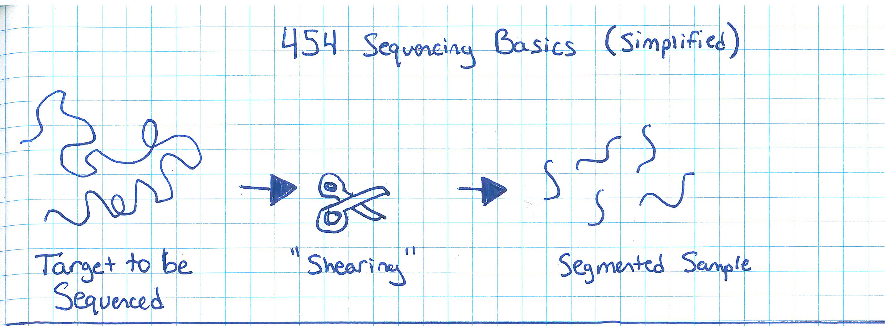
Step 2:Add adapters. 'A' and 'B' adapters are binded to the ends of the DNA fragments. The fragments are then 'unzipped' to form unzipped, adapter tagged strands. 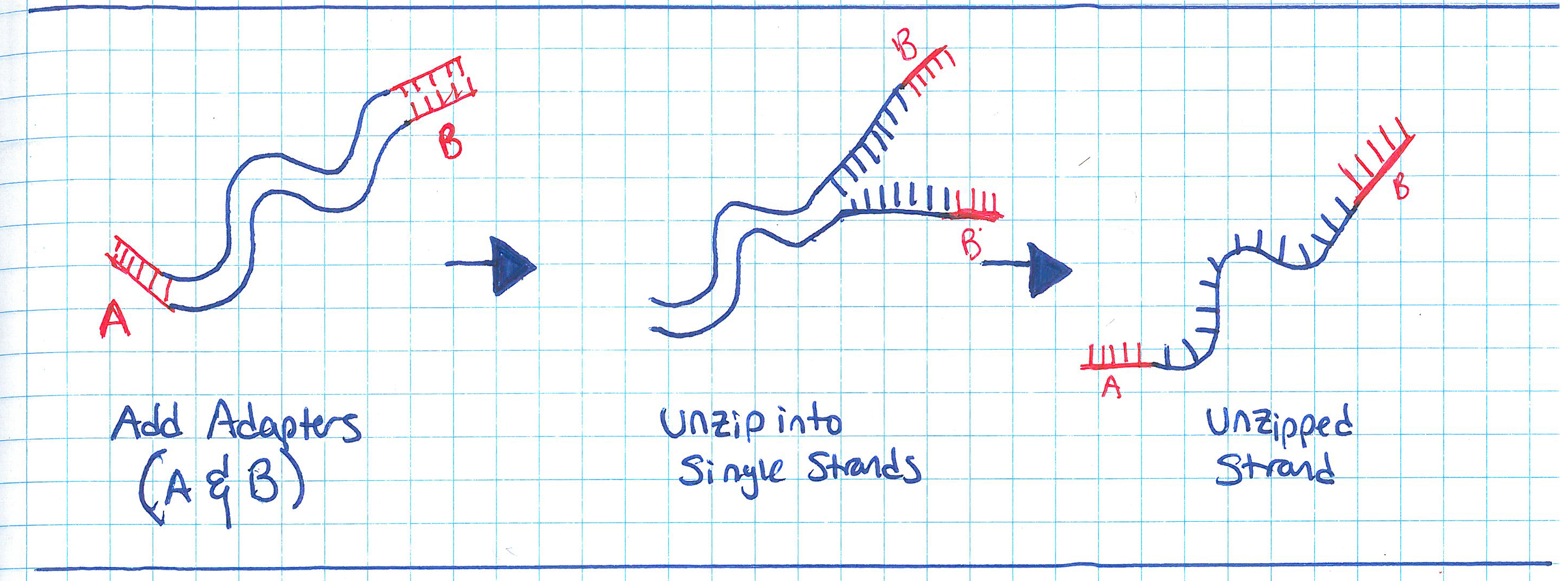
Step 3:Clonal amplification of fragments (take a single sample and make a whole pile of them). This can be done with PCR, and you end up with a pile of cloned segments with associated A and B adapters. 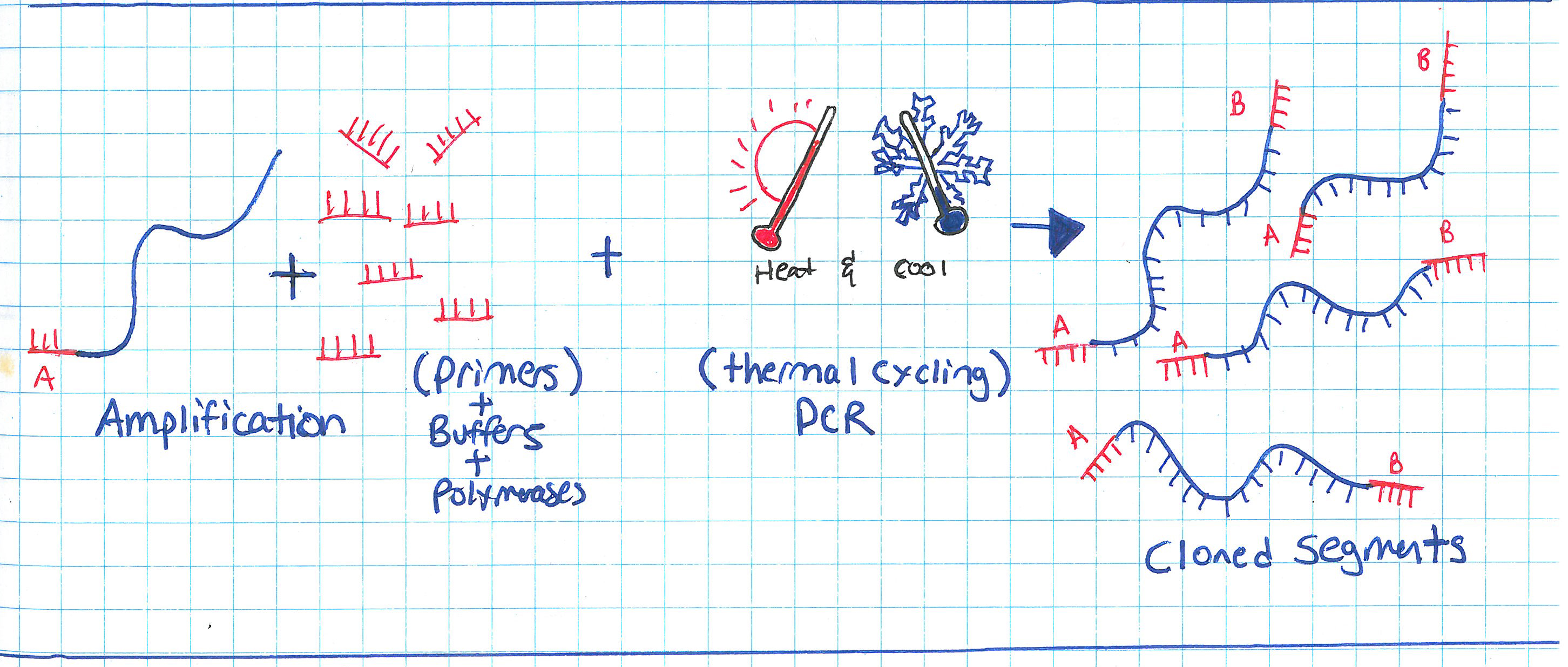
Step 4:Pump clonally amplified fragments into the P2P plate (part that sits on the optics path). Inside the P2P plate are a bunch of 'wells' or small containers. Inside each of these wells is a 'bead' or solid location for segments to bind to. 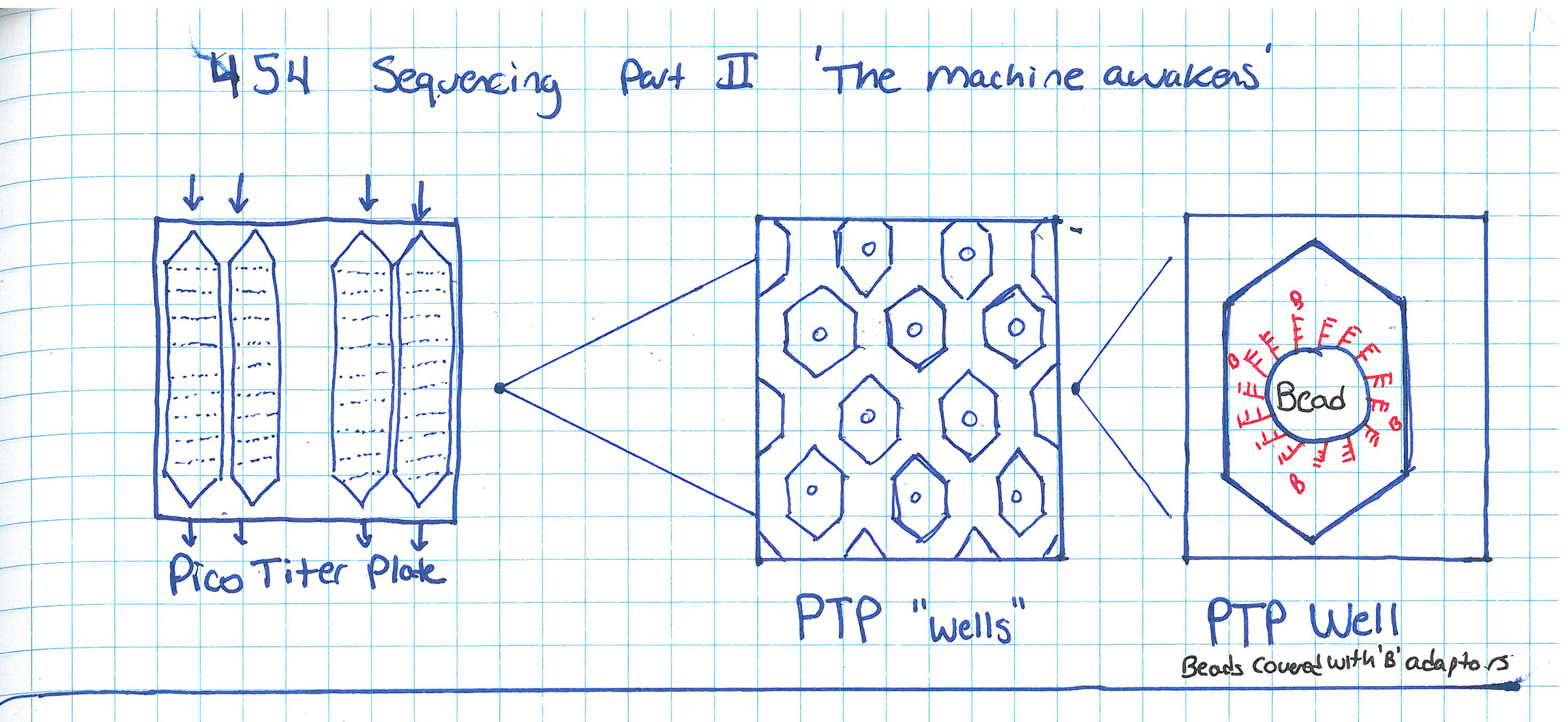
Step 5:Single strands bind to 'bead' in PTP wells. Shown is one 'well'. After binding has completed, wells are 'packed' with holding material (tiny clear beads). This prevents things from moving about, or from the bead falling out during the washing / pumping phases below. 
Step 6:
Ok so how does this thing work. 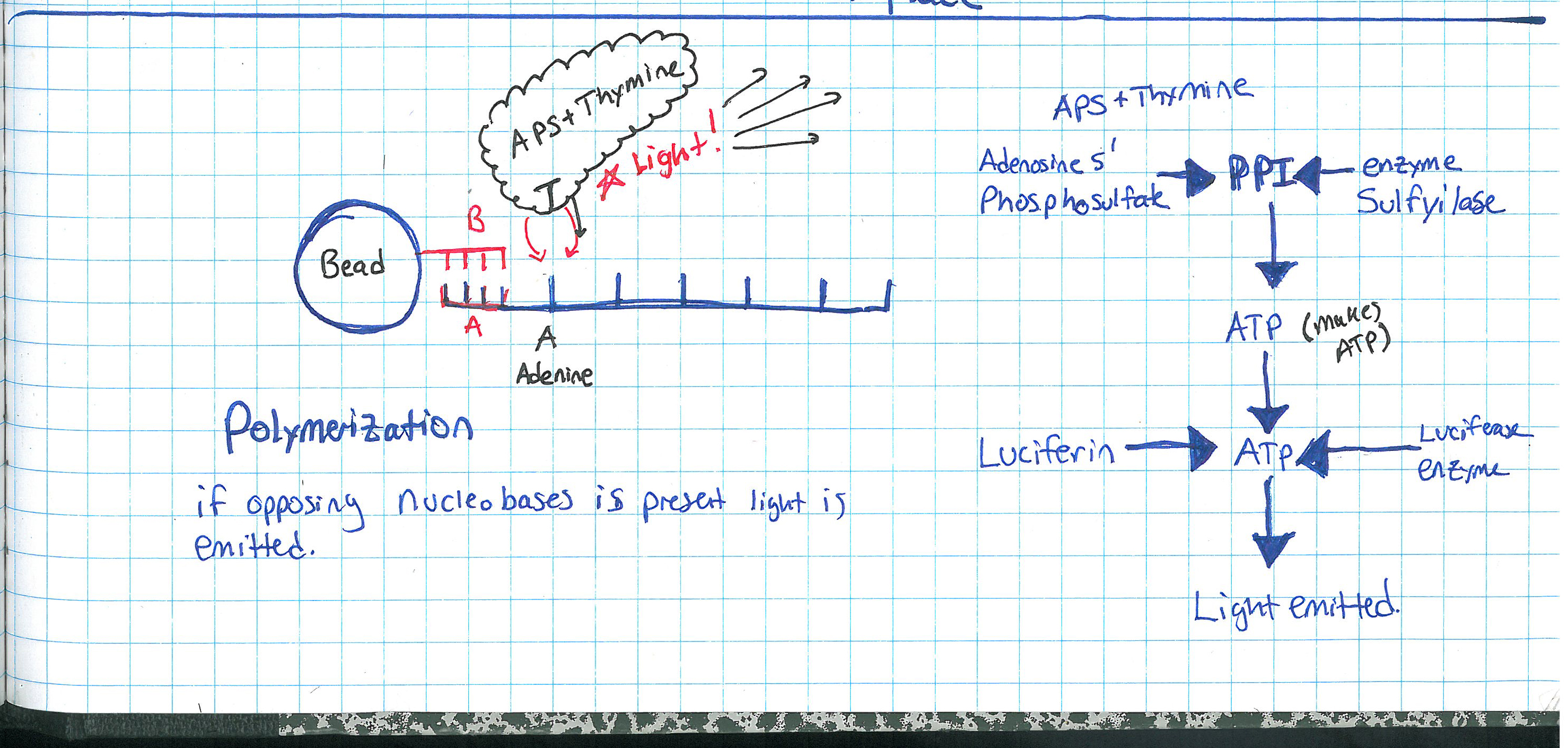
RINSE AND REPEAT GENOME SEQUENCING?yes, suprisingy yes, At the end of each cycle the PTP well is 'washed', the bead and single strand sequence fragments stay in place, but any dissolved AP5 is washed out. This doesnt just happen once, it happens quite a number of times in parallel, depending on the PTP plate size and number of wells. The sequencer pumps in 'nucleic acid + AP5' observes on all wells if pyro-sequencing has occured (if light is emitted) as well as how much light, and keeps a log of these events. After cycling through wash and 'other nucleic acids + AP5' it does a pile of data processing looking for similar sequences. These similar sequences get sewn back together. This re-assembles a sequence that was physically sheared into smaller sequences. Because the same sequence occurs in parallel, a higher probability of accurate data is obtained. 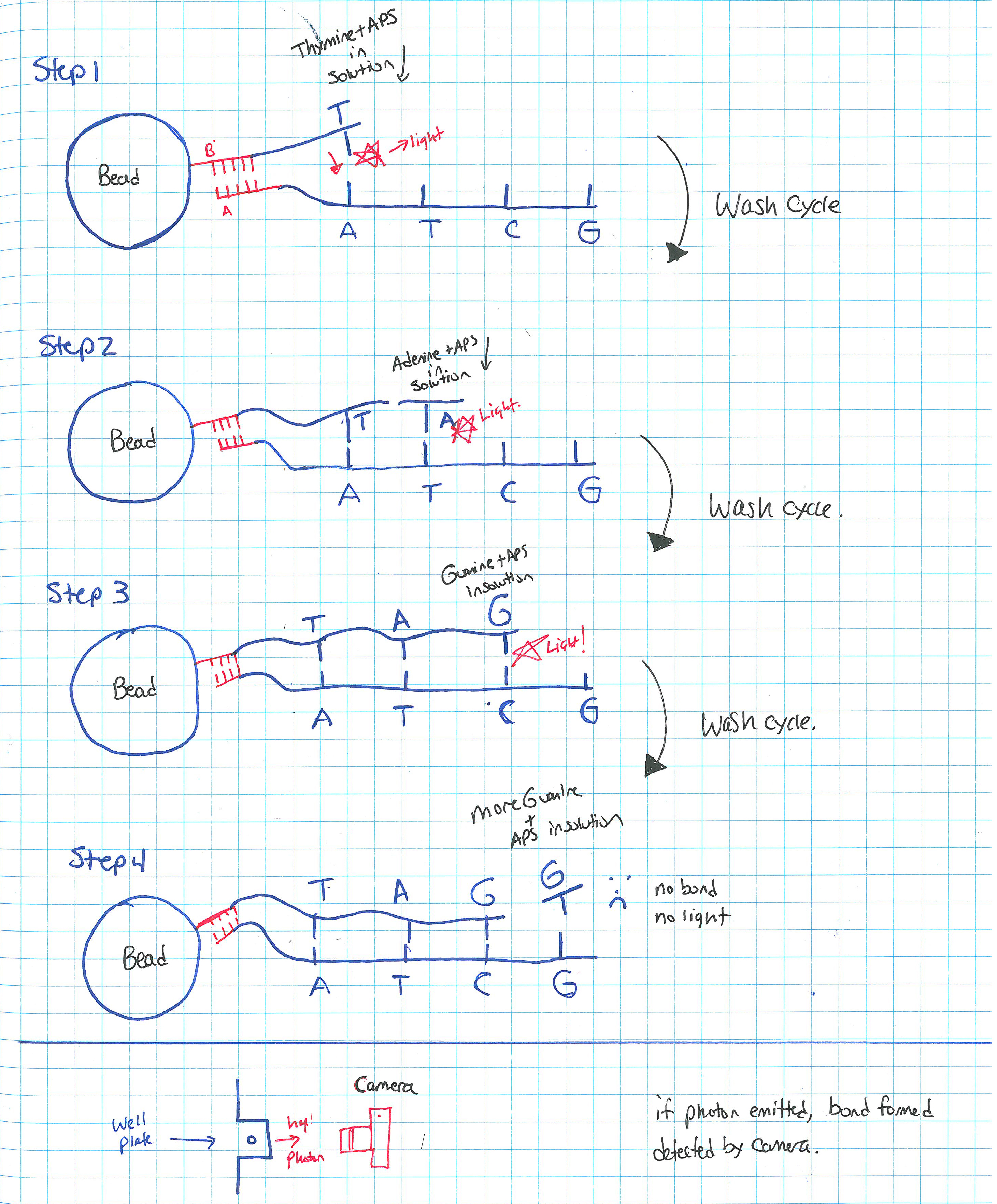
How does the system deal with multiple, in-line bindings?In each chemical pumping cycle the camera analyzes a well, if 3x the brightness in comparison to a single event is found it is categorized as three binding locations. Nominally, the camera images reaction plate and records pyrosequence photon emissions, The machine washes out reaction well of remaining nucletoide and switches to another nucleotide. Cycle continues until base pairs filled. 
Shown here is an excerpt from a sales manual, showing the PTP plate, the PTP wells, the 'bead' used as the solid surface. 
What does the system look like?Super-simplified, the A T C G and WASH tanks are each tied to a small peristaltic pump. The tanks and sipper tubes are actually visible (right). The whole sipper tube assembly rises up out of the solutions. The 'waste' container is actually shaped around the pocket that holsters the reagents. When removing, take care, it may be full of liquid. 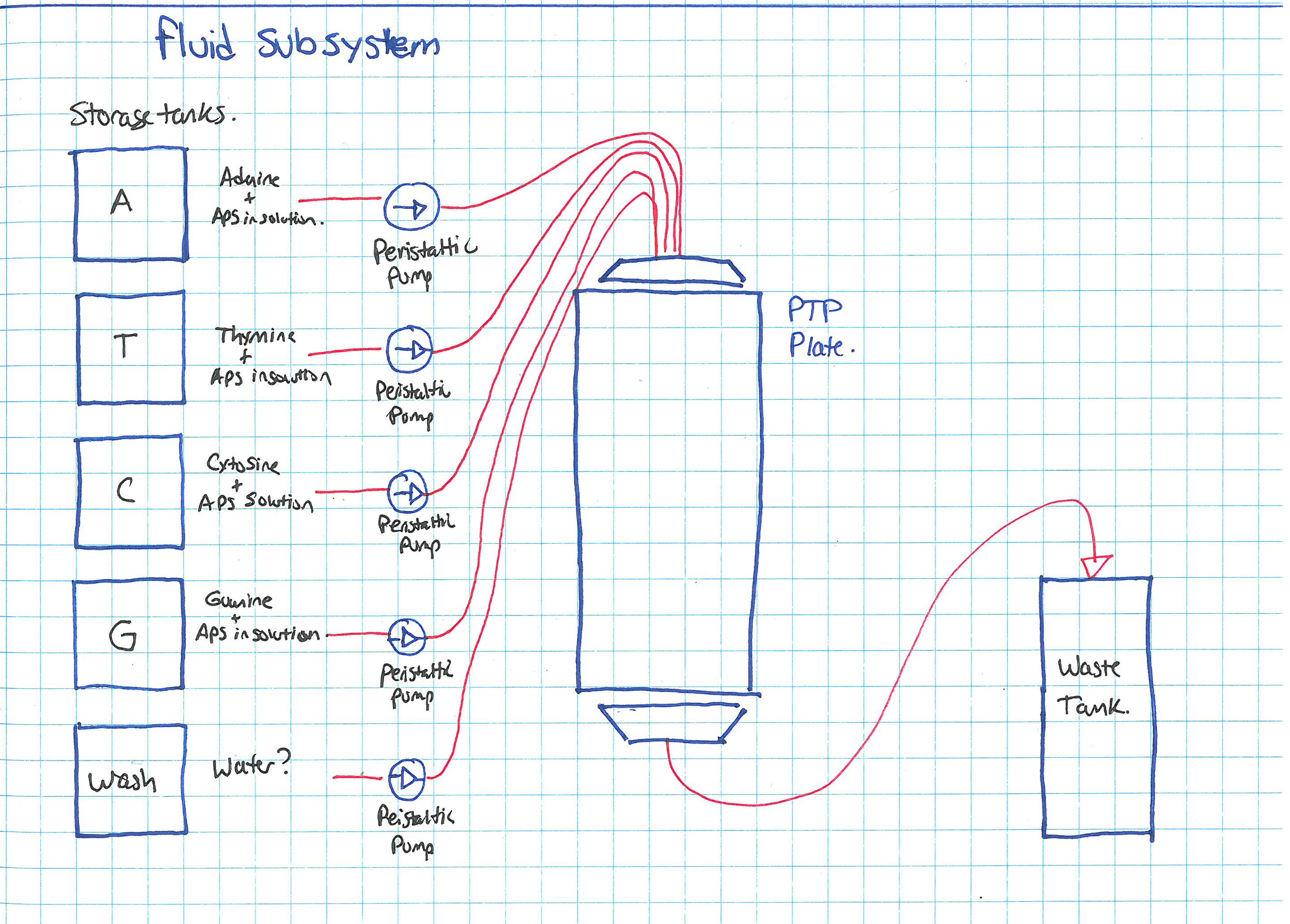
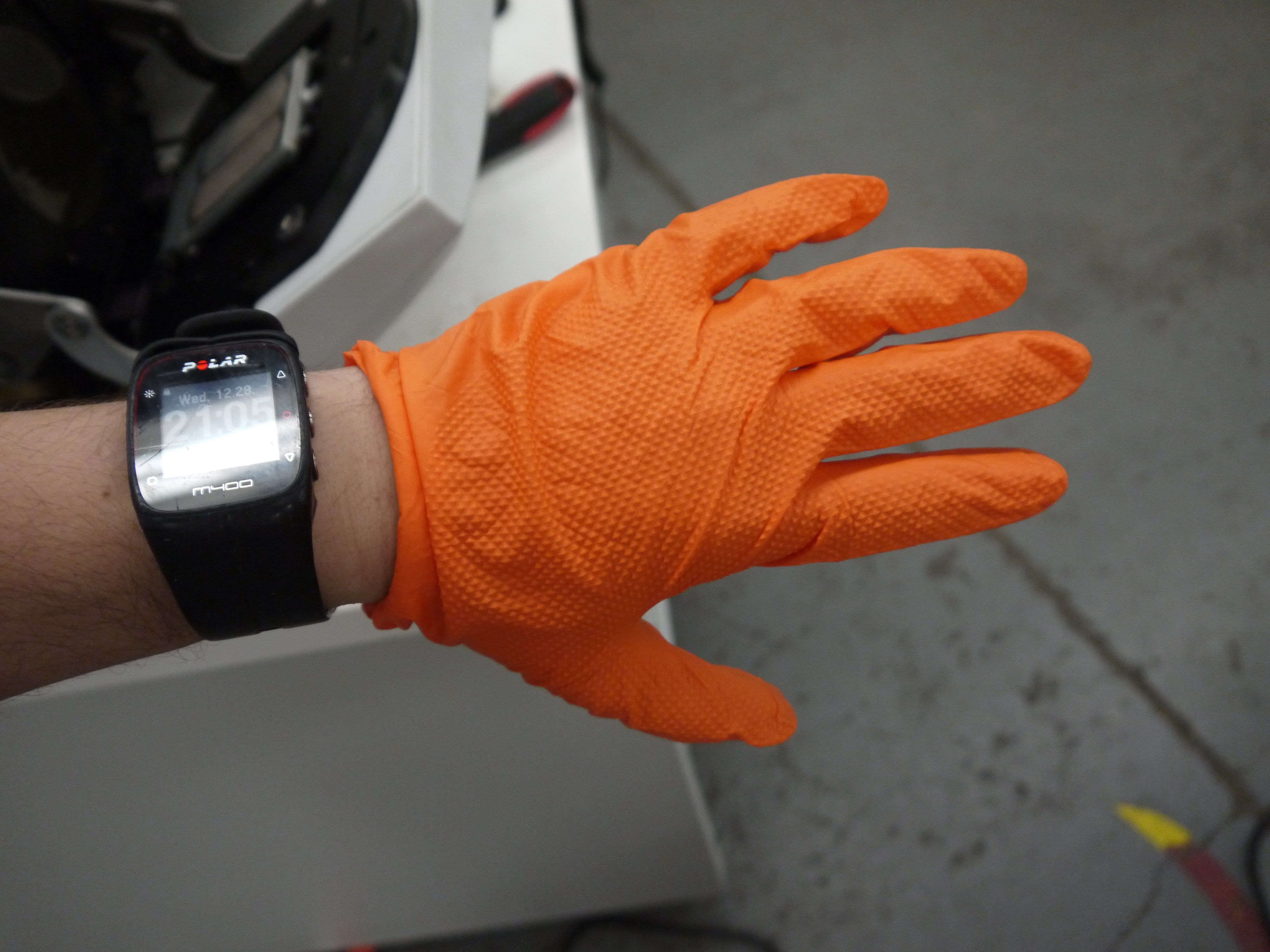
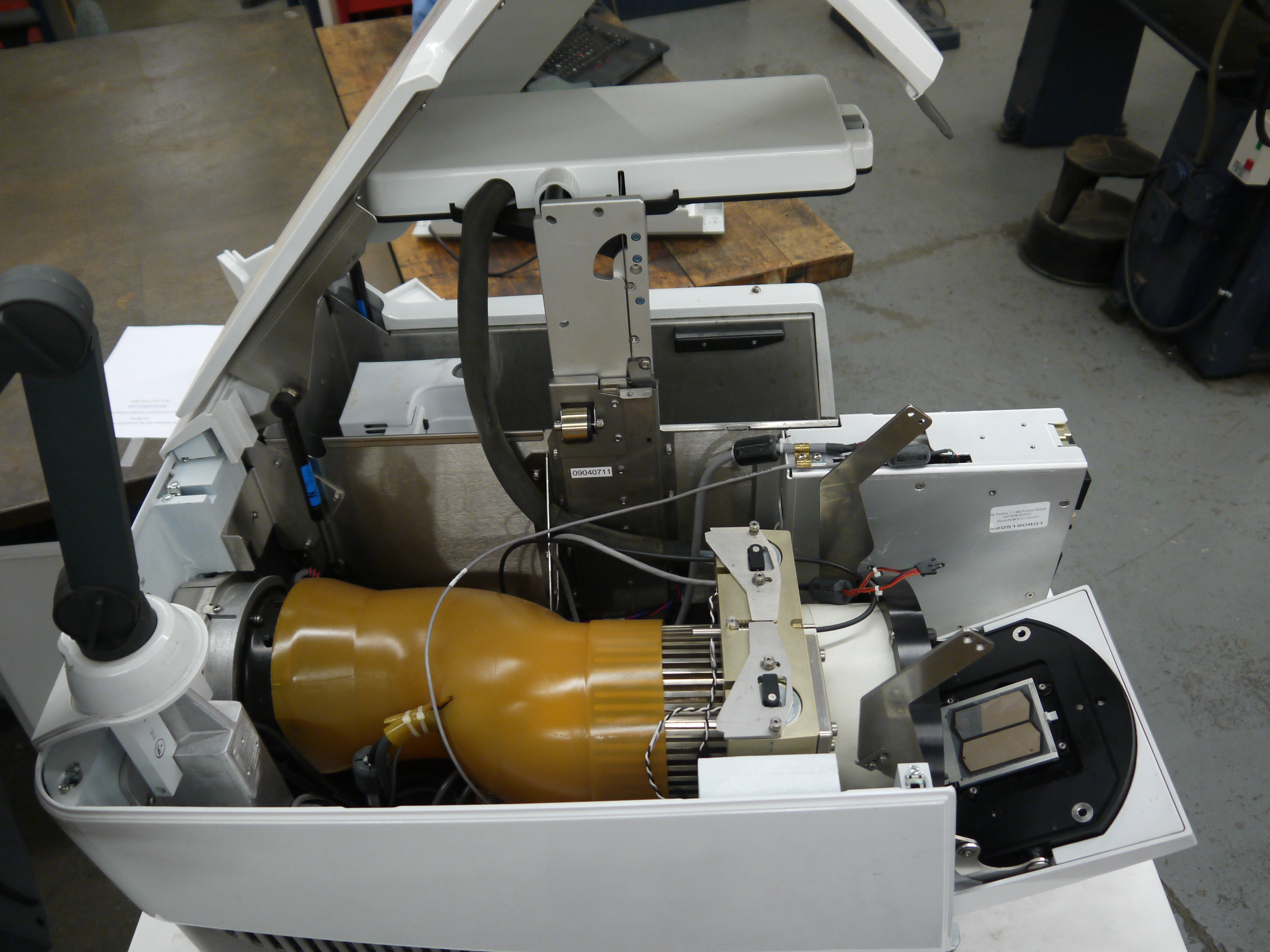
Camera ExtractionOk time to extract the imaging hardware GLOVE UP. This is a bio-contraption, that probably processed e-coli or some other bizare biological goo. While it was cleaned, it doesnt hurt to wear some hand protection. 
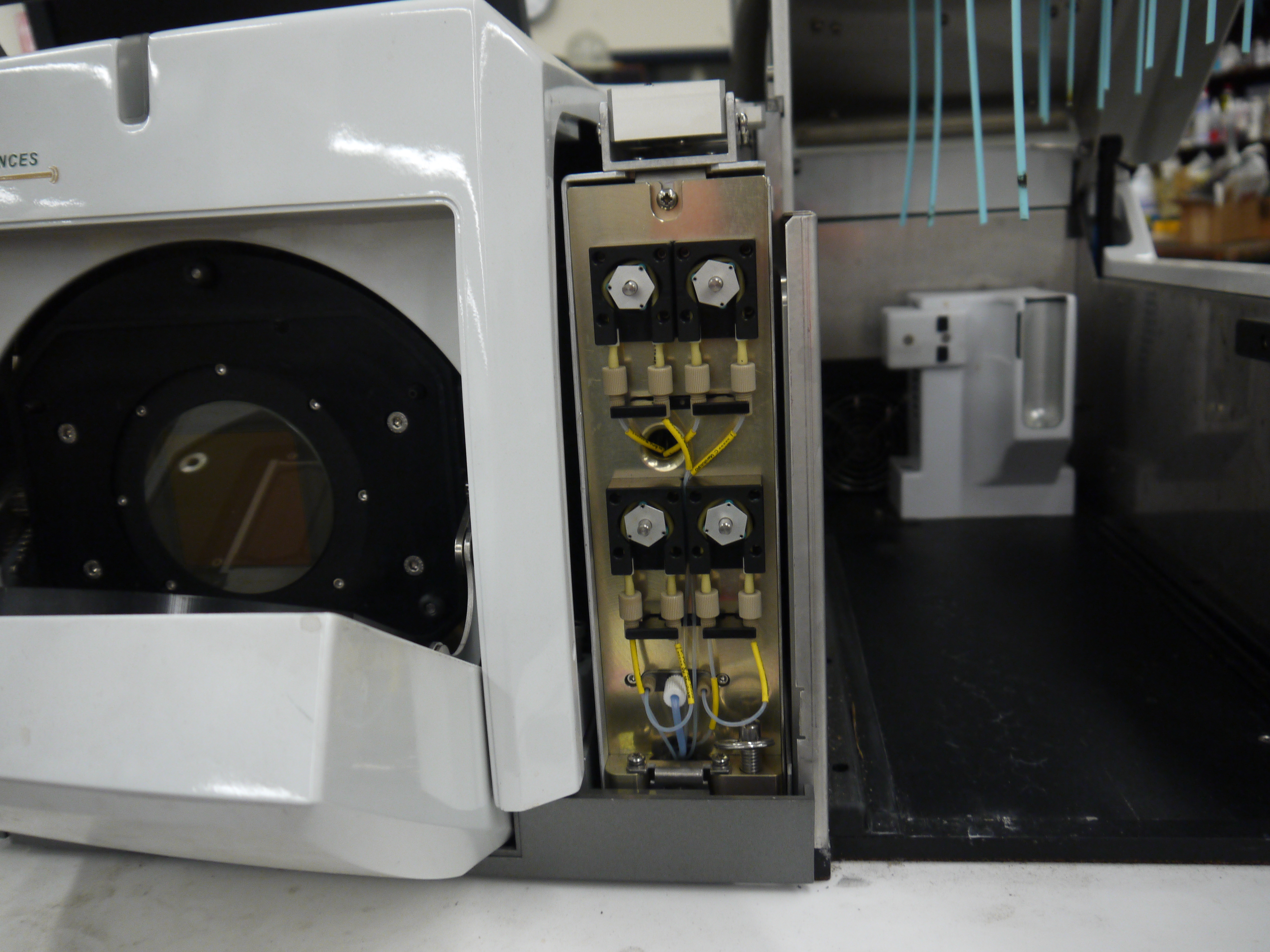
Peristaltic Pump moduleThe hardware behind the 454 sequencer is fairly well mechanically integrated, this whole block is a modular pump assembly, where an offset cam pushes liquid in a non-contact way to pump either reagents or wash fluids into the PTP plate or throughout the machine. 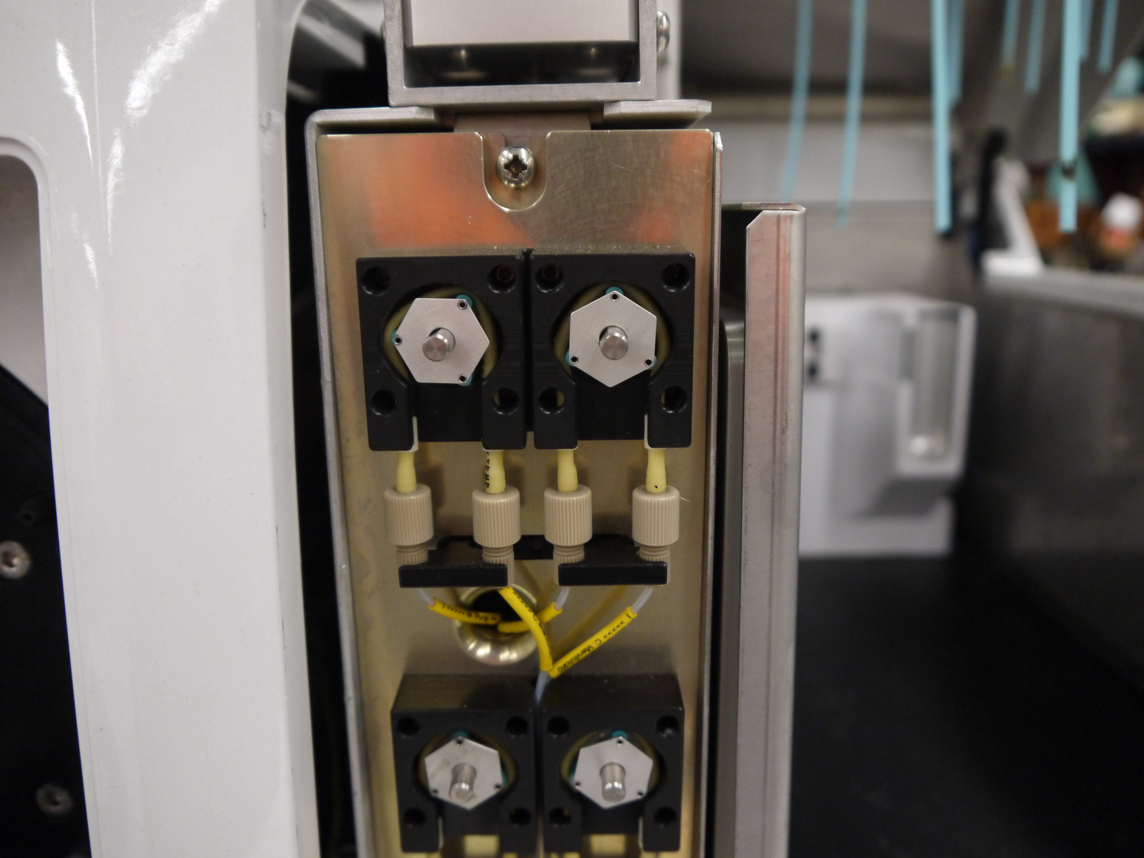
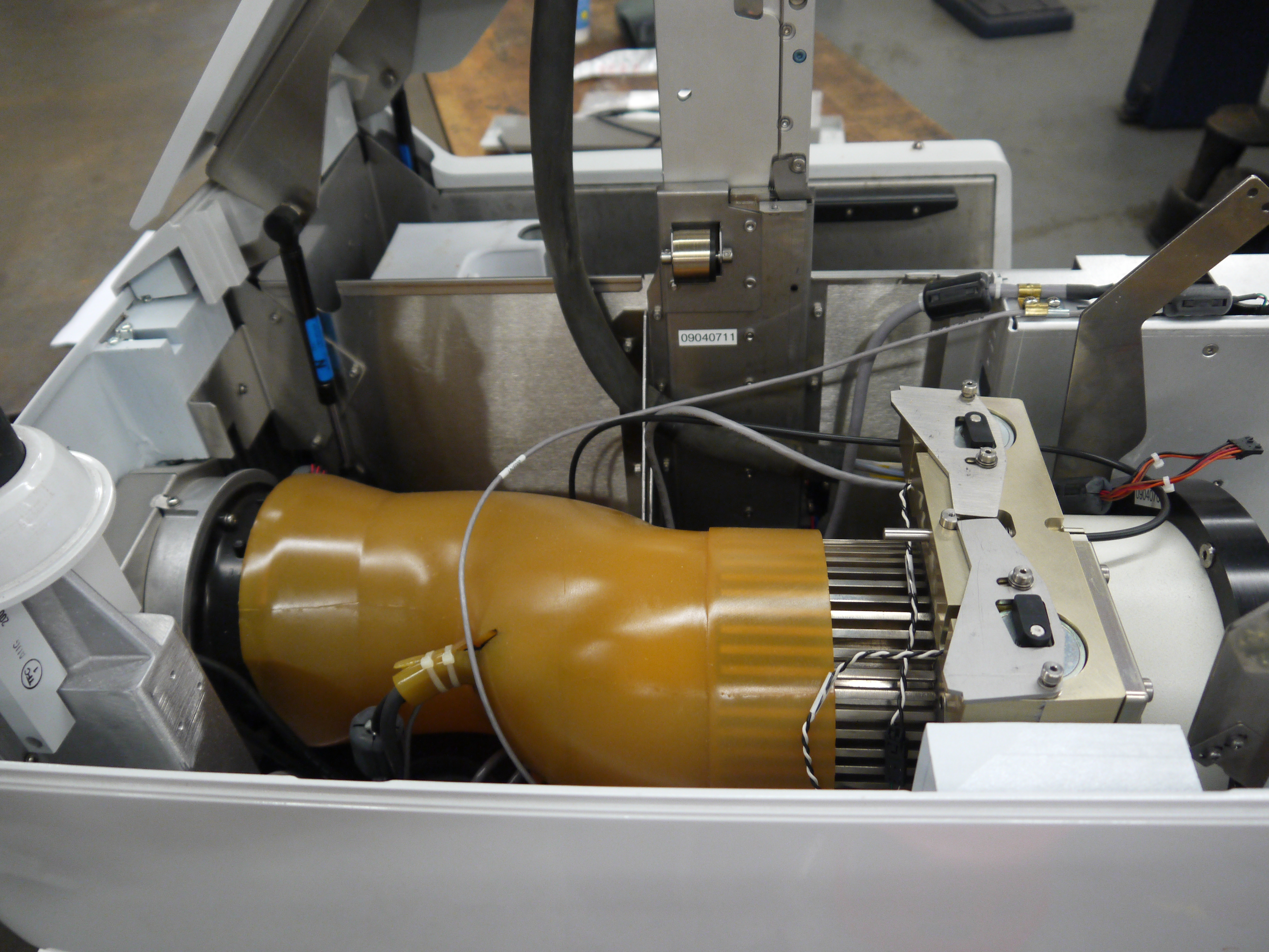
Removing the handle and associated cover hardwareI cant make it more clear, this thing is built like a frigging tank. The case is cast aluminum. The handle takes some prying and a few allen screws to remove. 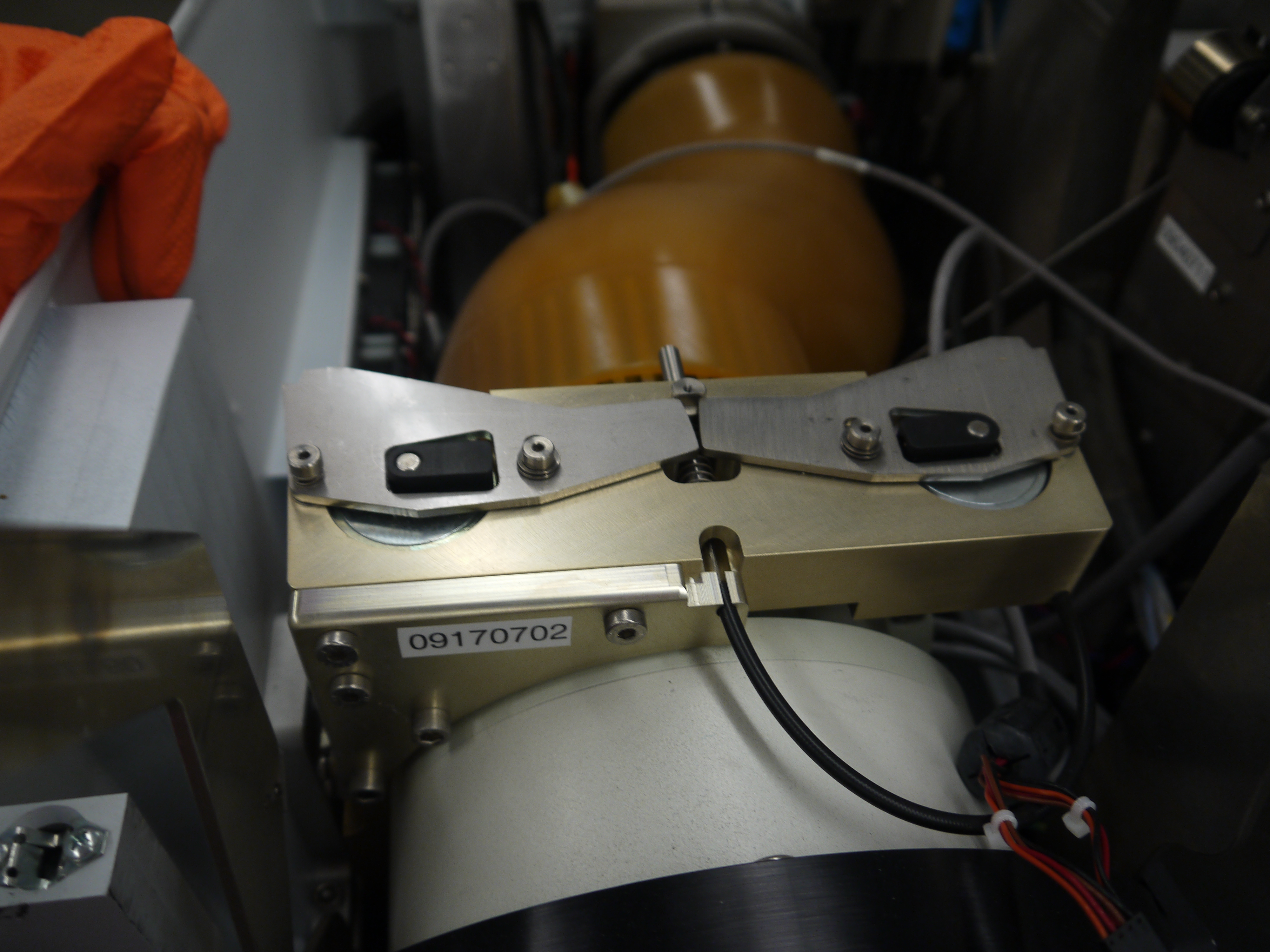
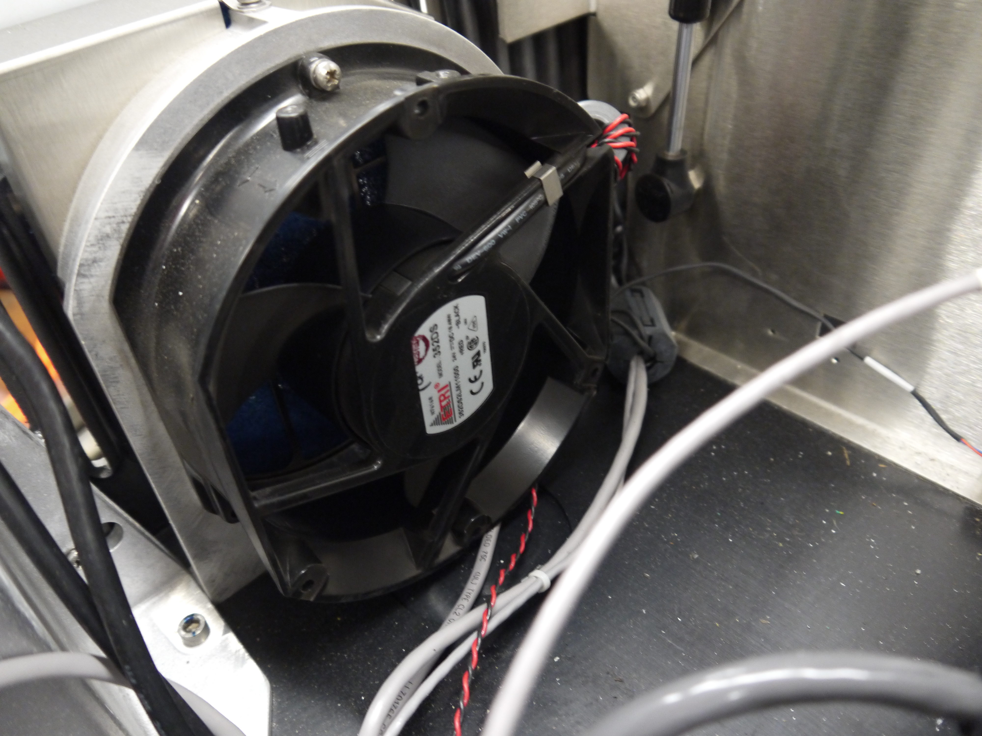
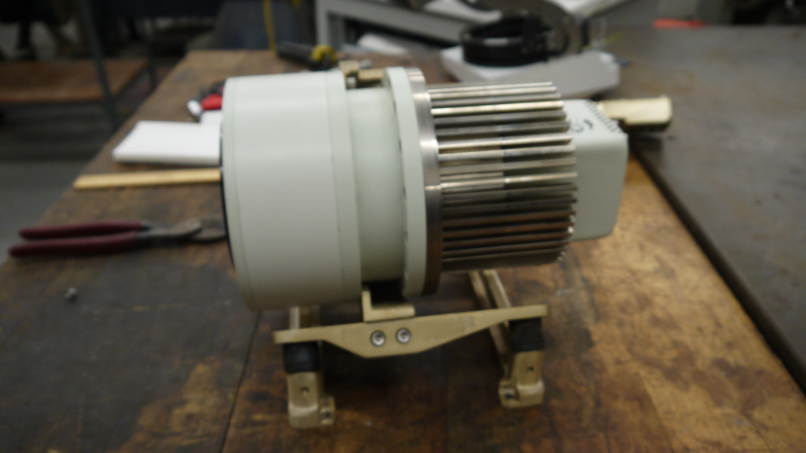
Removing the fan rubber shroud thing This is a curious design, the camera has a few cables protruding out of its back-side, but, it needs forced cooling to keep the thermal buildup on the back of the peltier junction reasonable. To do this, a rubberized air-guide was made, with a small slit to pass cables out. I didnt need this as its specific to the enclosure, so, off it goes. 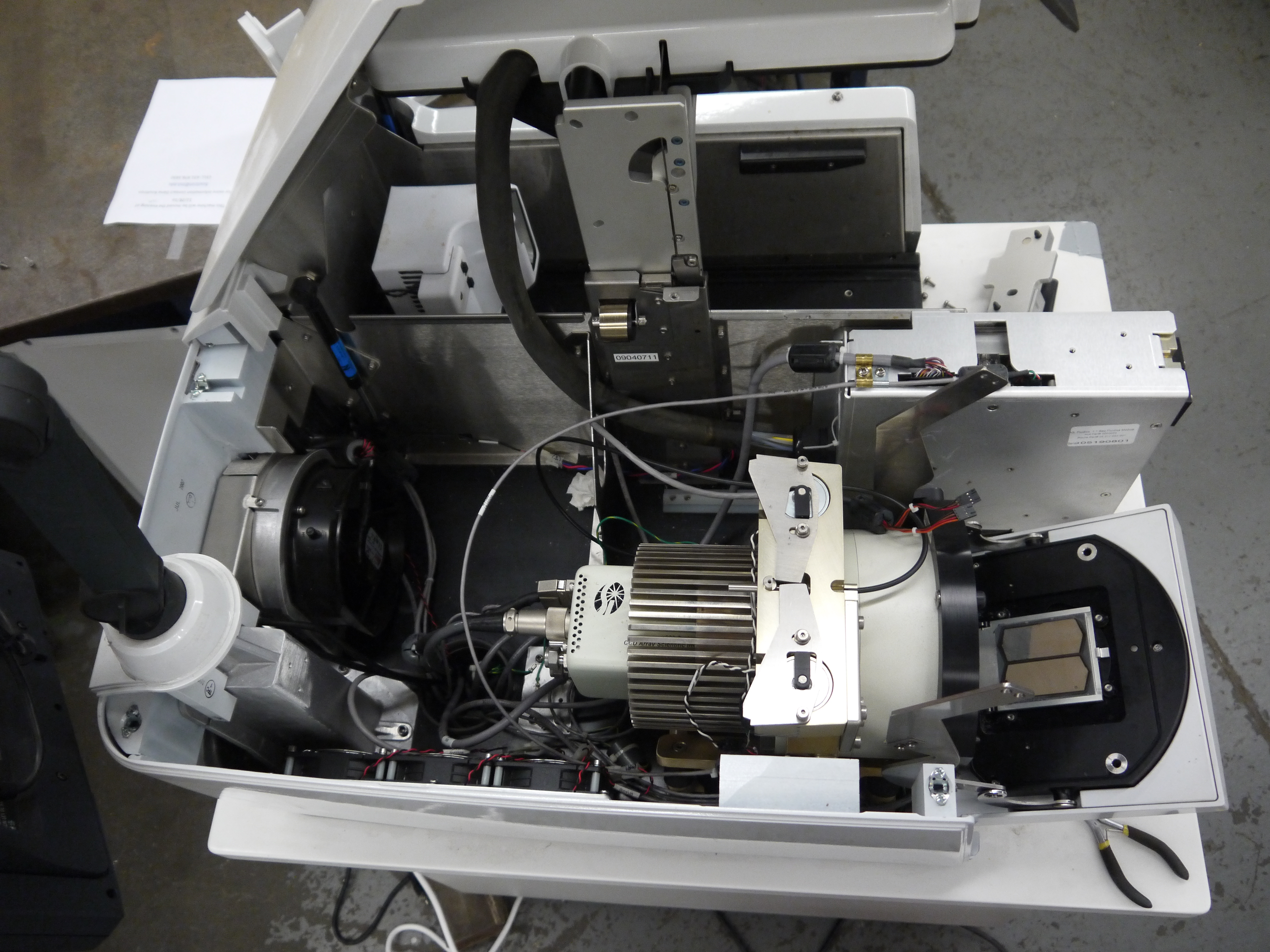
A pile of connectorsThe camera itself is quite the beast. The data for the camera is passed over copper using a quad rs-422 bus. The connector is shown. Power is provided through a round twist-lock connector. This unit used air cooling so the liquid coolant ports were capped off. 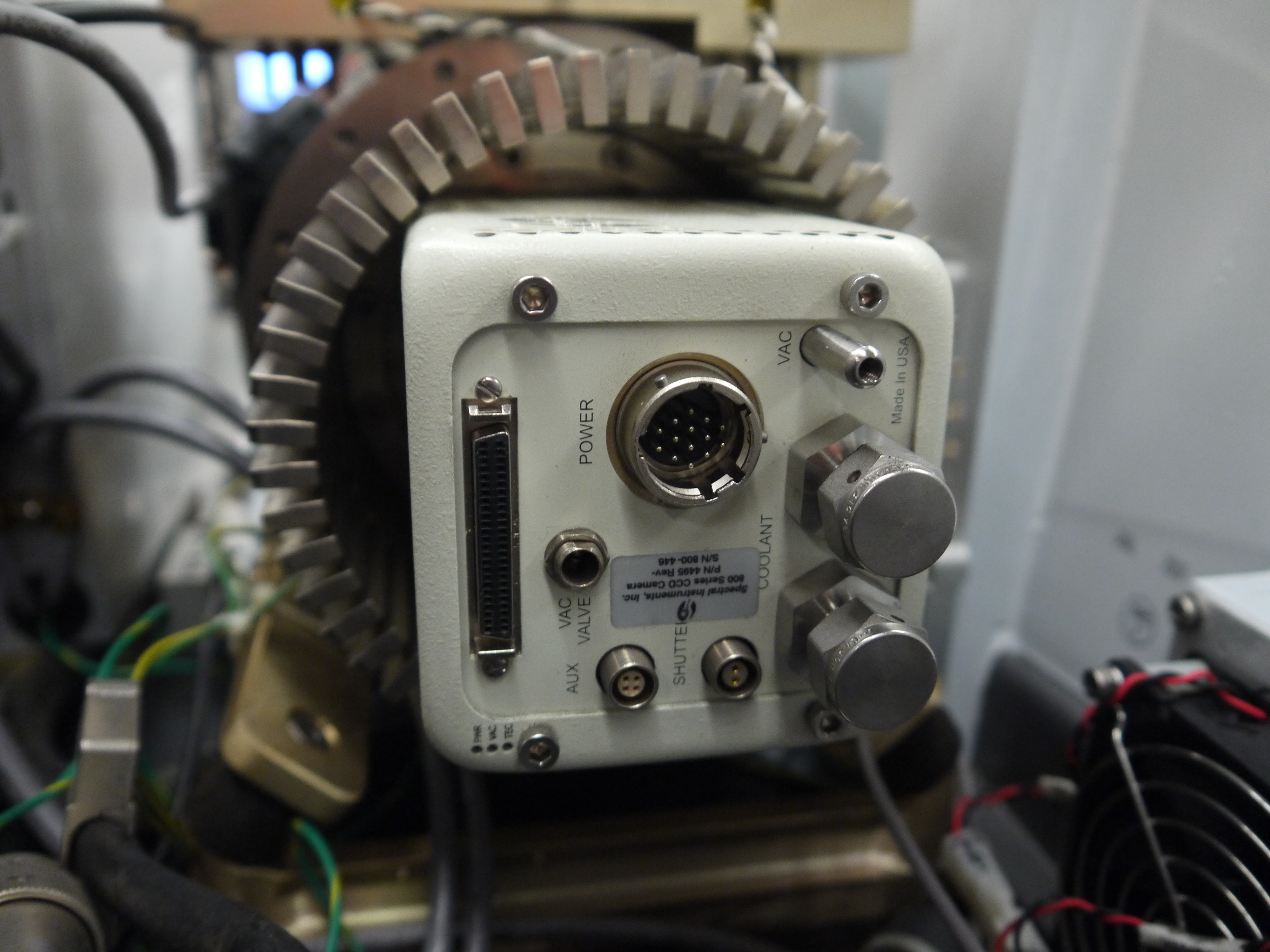

CoolantHow much heat could a camera probably need to be rejected. Turns out Quite a lot. This fan was a bit overkill, given that the unit is only really rated to run in a laboratory environment. Its ginormous. 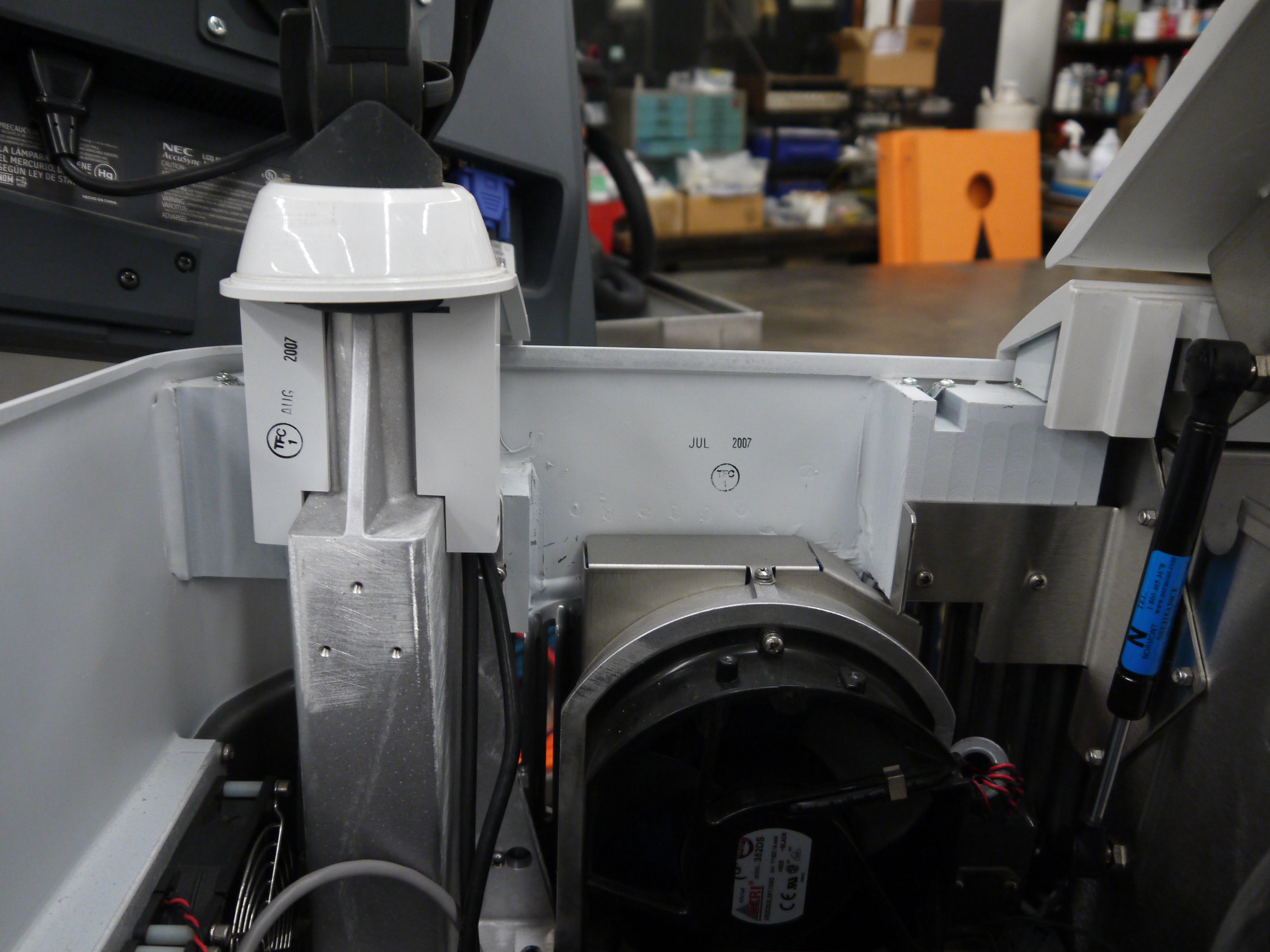
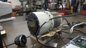
YOWZA, quite a sensor, er, optic?Here's a front view of the camera itself. Its a bit deceptive, you're staring at the sensor, but your staring through a packed fiber bundle array. what you ask? The sensor itself is further inside the camera, the fiber optic thermally decouples the outside of the camera from the chilled vacuum surrounded sensor. The packing density is quite high, only minor, repeating, artifacts from the optical packed fiber are visible in some images. 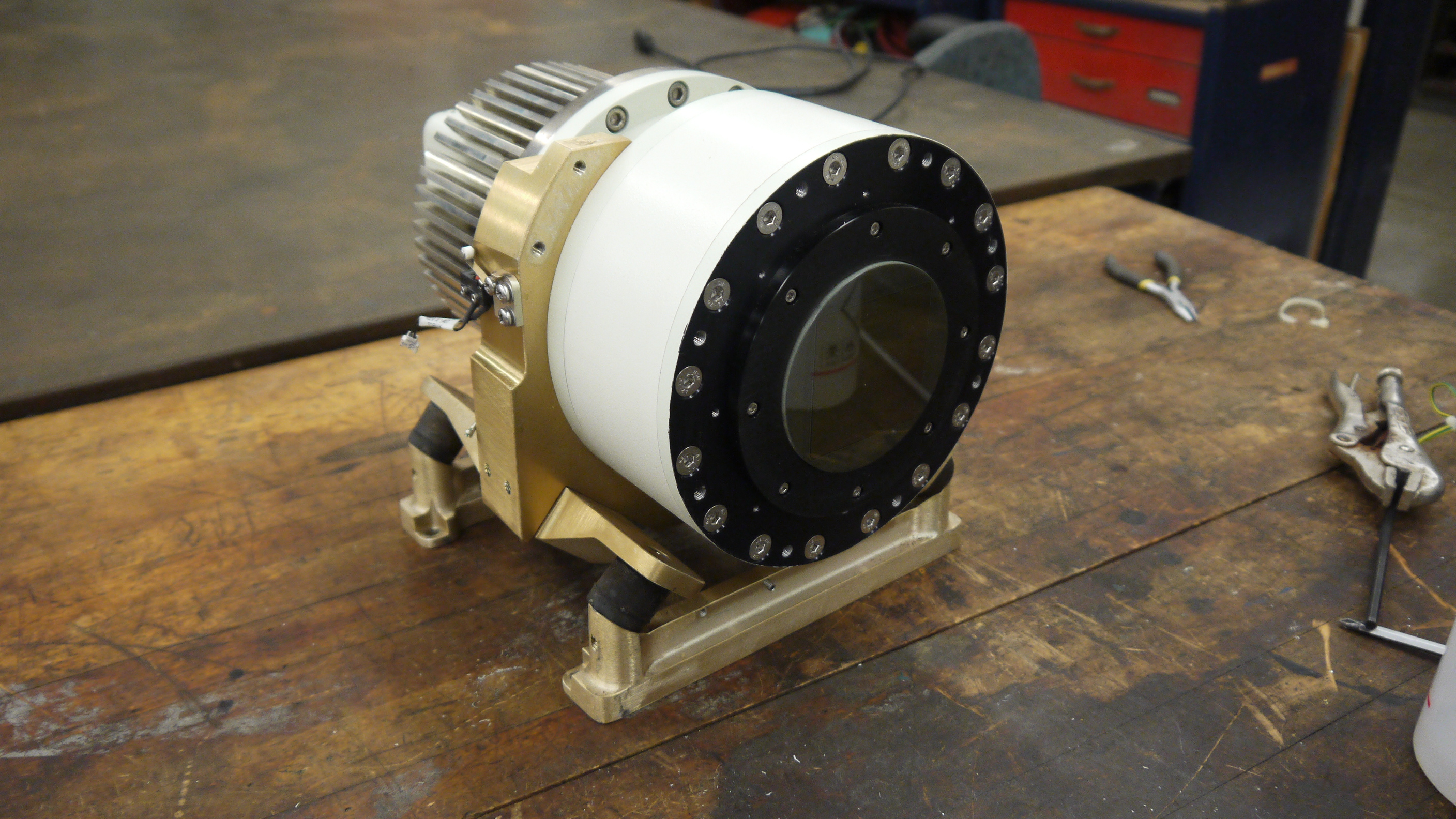
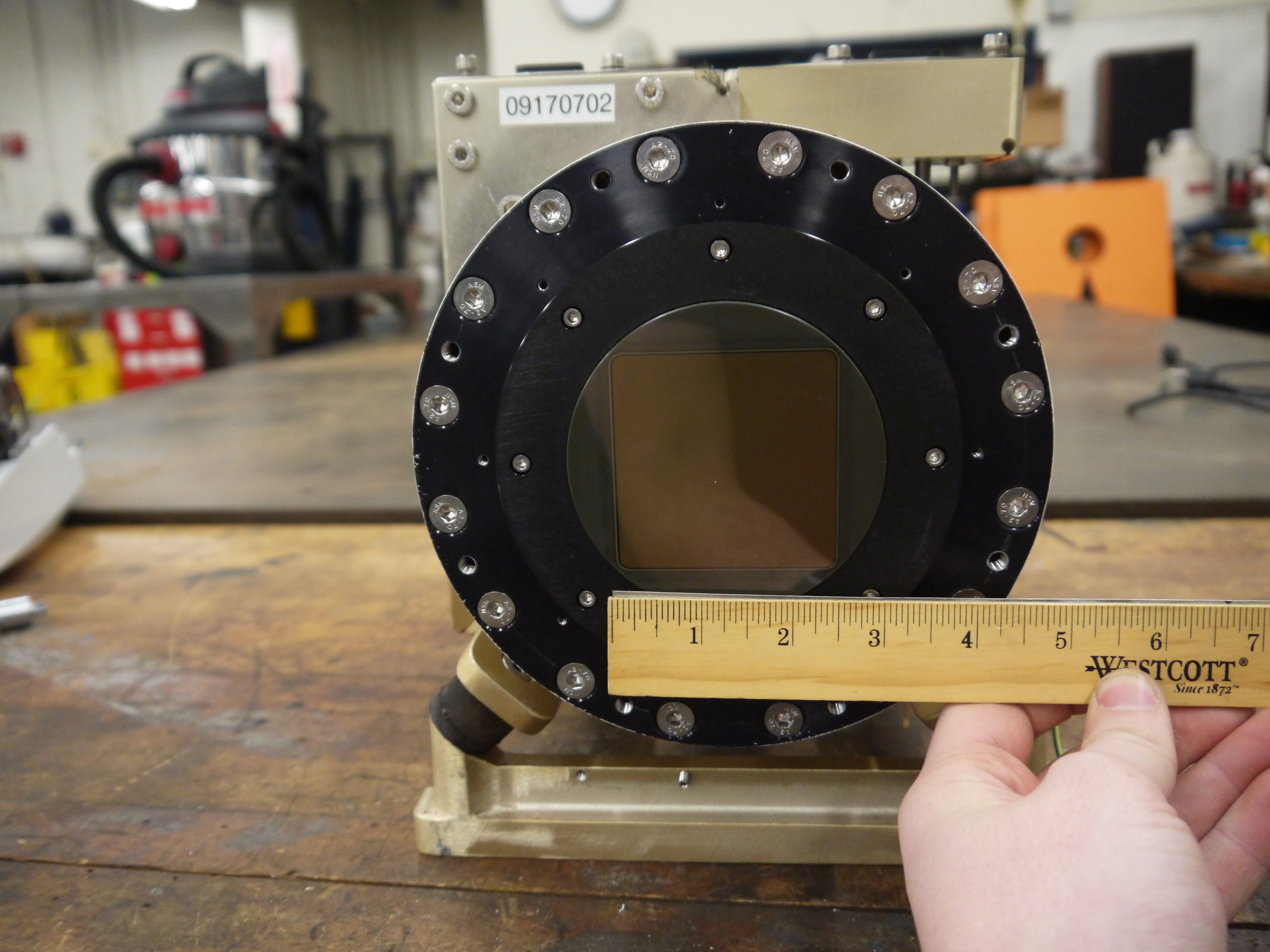
Shock MountsSo not only is the sensor in a vacuum, thermally chilled, and thermally decoupled from the outside surface, it has a cast base and shock dampeners. Quite the beast. 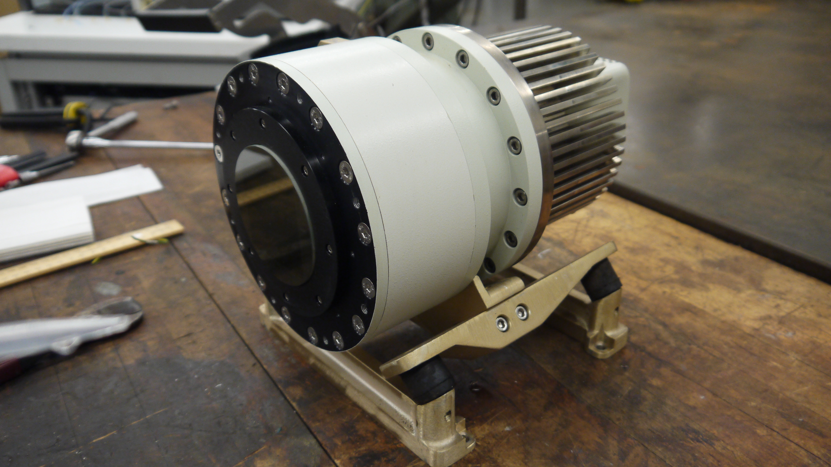
Bare minimum to turn over the cameraTo wake up the camera, I started by using the server that it came with along with the spectral instruments power supply. The server was used because it nominally already had the pci interface and should be able to handle the cpu load of reading and displaying the camera. 
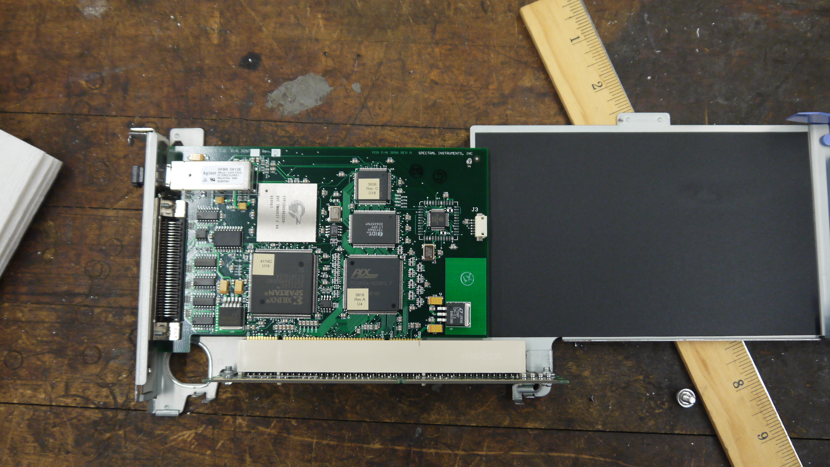
Camera interface cardThe card itself is a dual interface pci card, capable of either quad rs422 or optical interconnection. 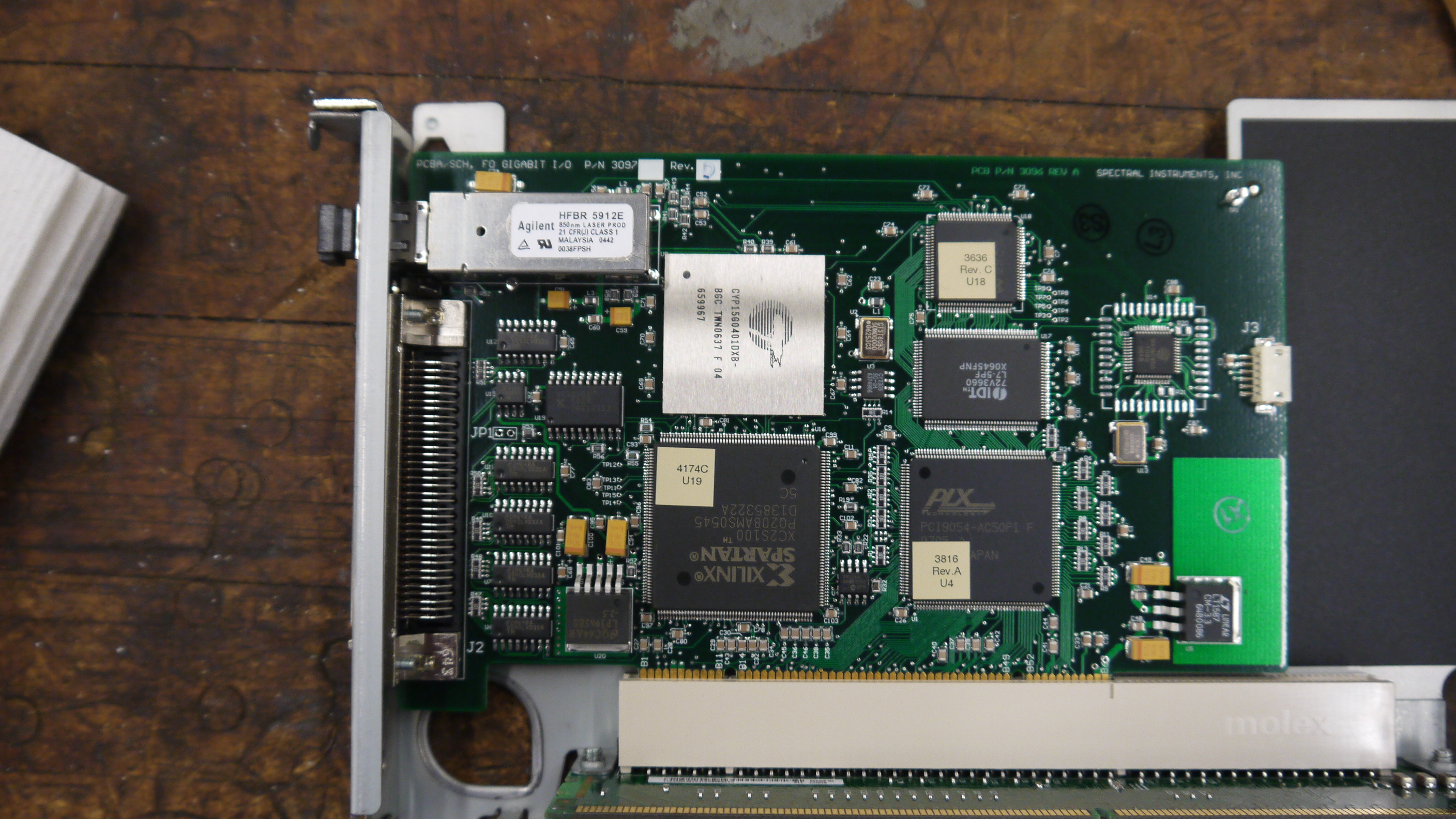
Windows, IBM hardware showing its ageI was gifted some sensor test software (windows) and figured that installing on a separate drive on the IBM machine would be a good fit, as it was designed to interface to the sensor. I found (luckily) a SCSI drive from my pile of misc dane-hardware and installed WiN7 X64 via the front DVD drive (machine refused to boot from USB flash drive) 
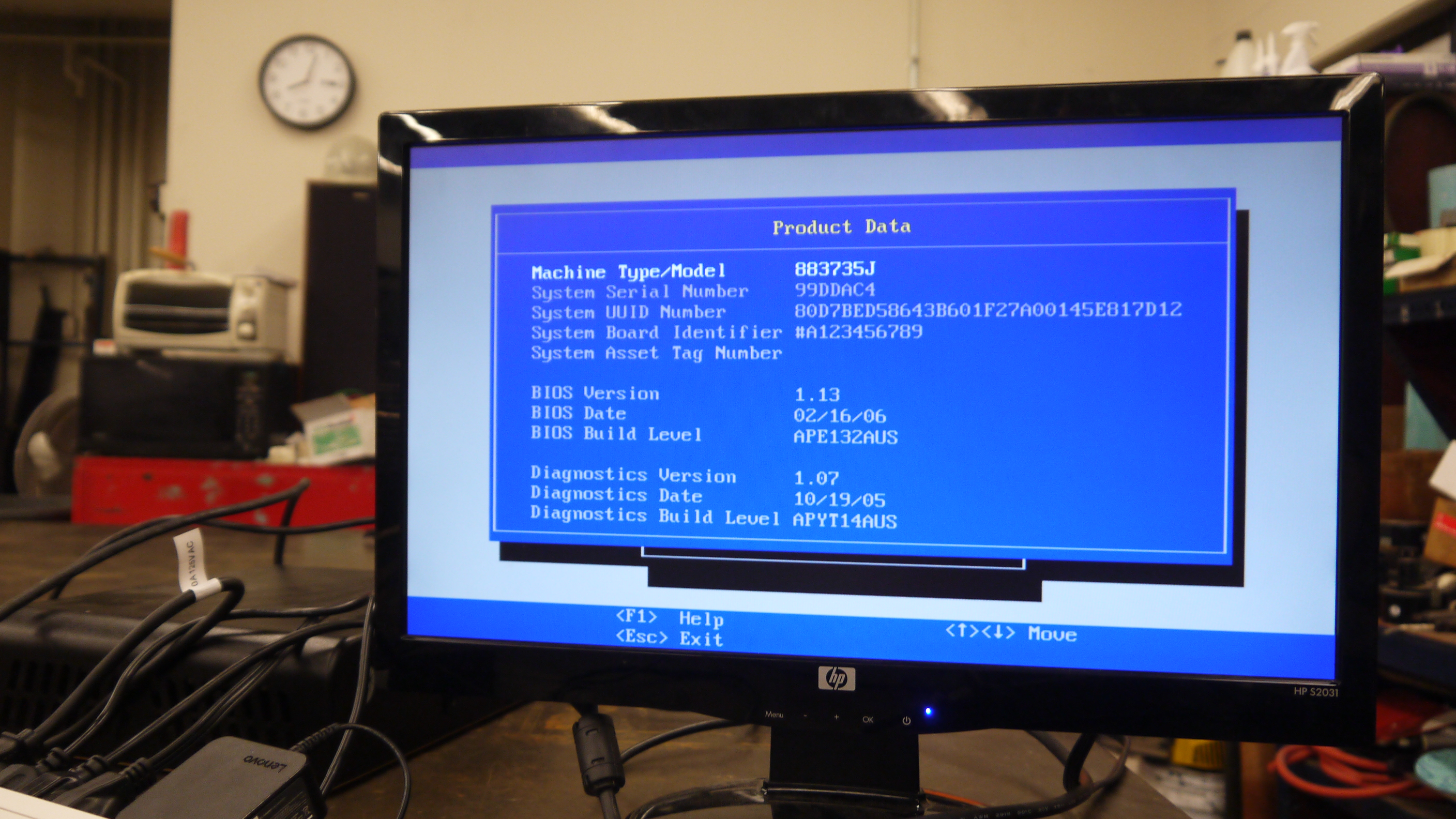
After getting some drivers installed, communications were up! I was talking to the camera, and heck, I could even request that it started to cool down for me! ANNNNDD BLUESCREEN... I spent a few hours toying with camera settings and going back and forth to figure out what was what, but i was hindered by kinda constant BSOD's and ~7 minute reboot cycles. I ran out of patience and it was day-before-new years. Time for some new-er hardware. 
Hardware upgrades...It was new-years eve and I needed my dose of science, I headed off to a nearby MicroCenter and purchased $140 of modern tiny pc board with PCI, processor, ram and PSU. The whole ordeal took less than 20 minutes and within that hour I was back on the bench, starting with a new windows install. Testing on the IBM did indicate the camera interface card was working quite well. 
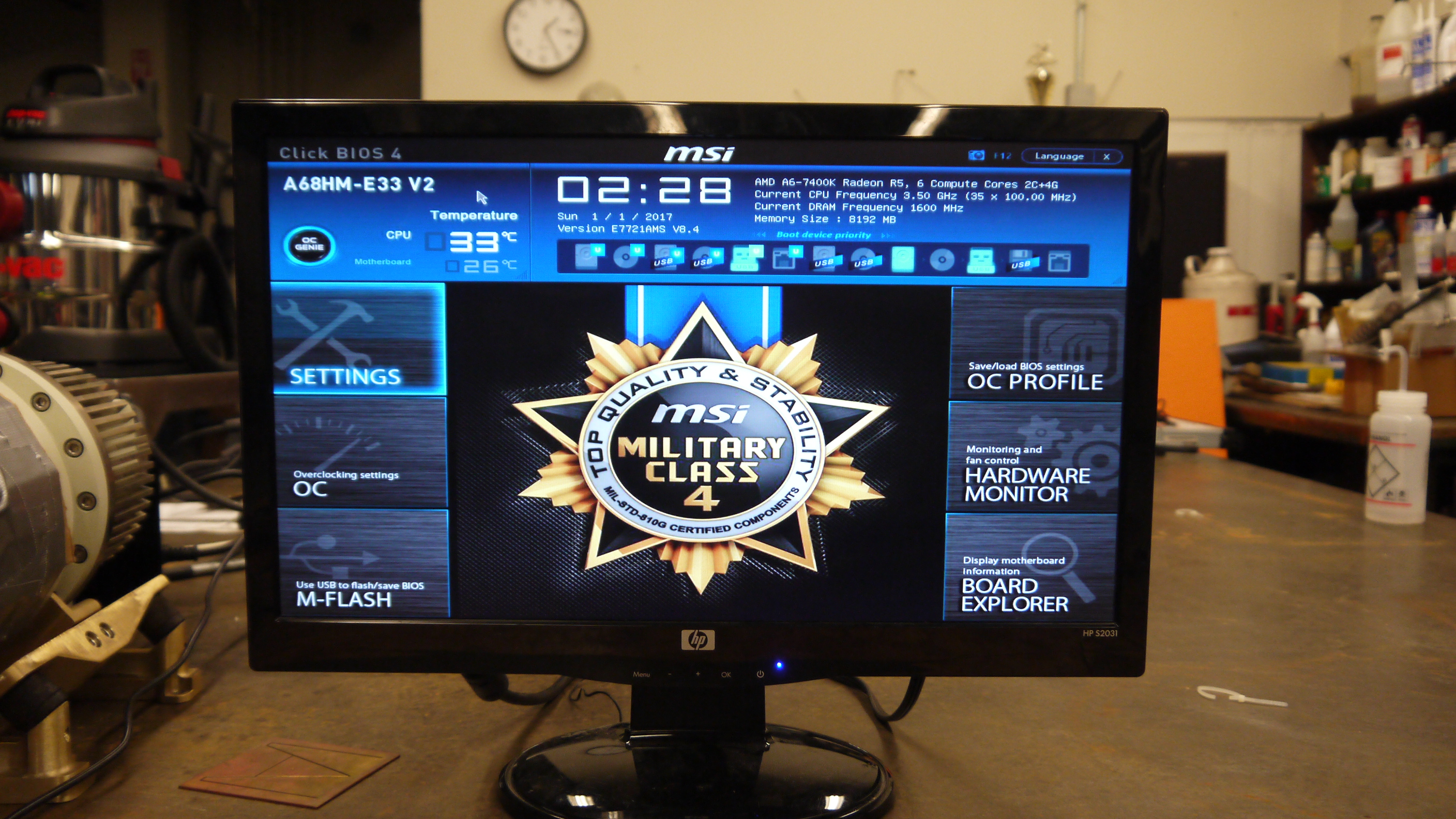
I did a 'Bayley Wang' and just used the mother board box to act as the case. Yes its cringey, but alas, this was for science. I haven't toyed with a modern bios in ages, and this was kind of a surprise. I just wanted to have it boot from USB, this looked like a frigging video game, in the BIOS itself. Even more curiously, i had a spare SSD (found in the electronics trash), and lo, a fresh windows install and I was back in business. 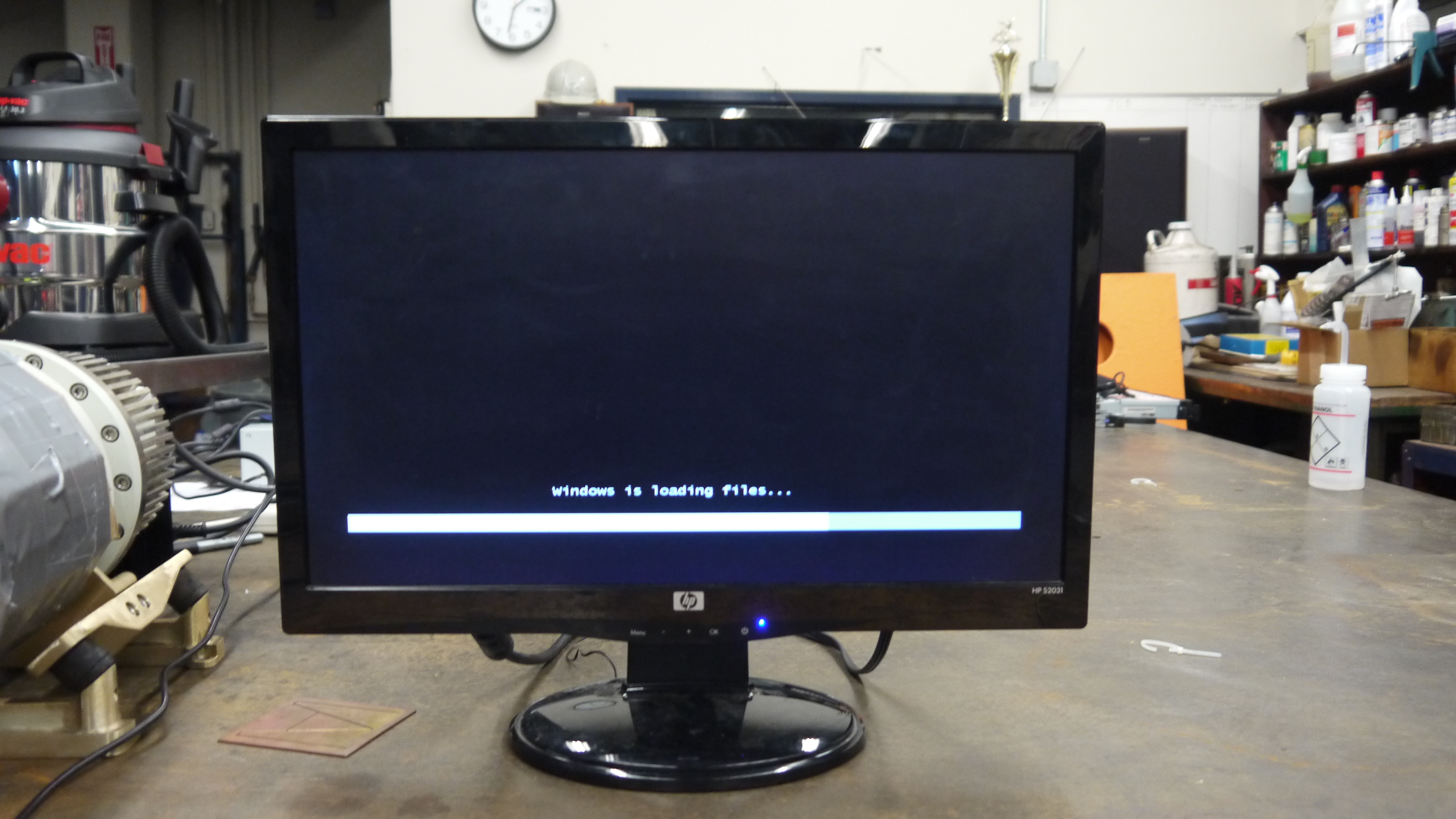
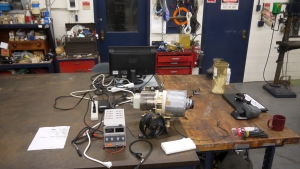
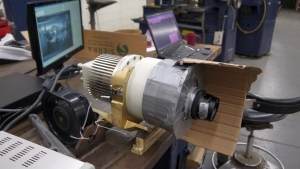
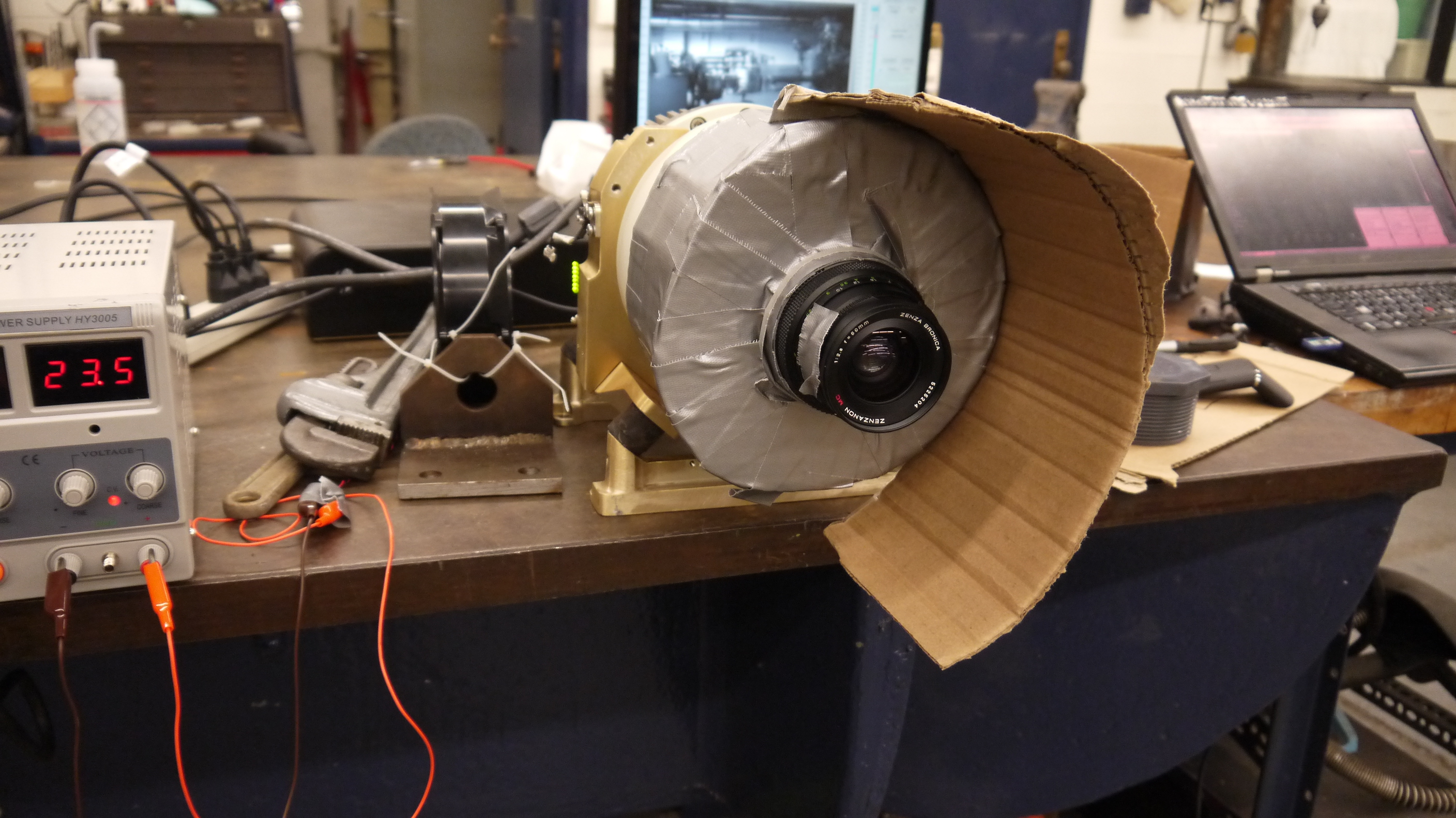
The setup was fairly straightforward, the Black Box is the camera powersupply, the 'computer' lived in its cardboard case, and the PCI camera interface card sat firmly pluggedinto the test computer. The stock cooler fan (24V) was used, running from an external variable power supply keeping the camera heat sink cool. 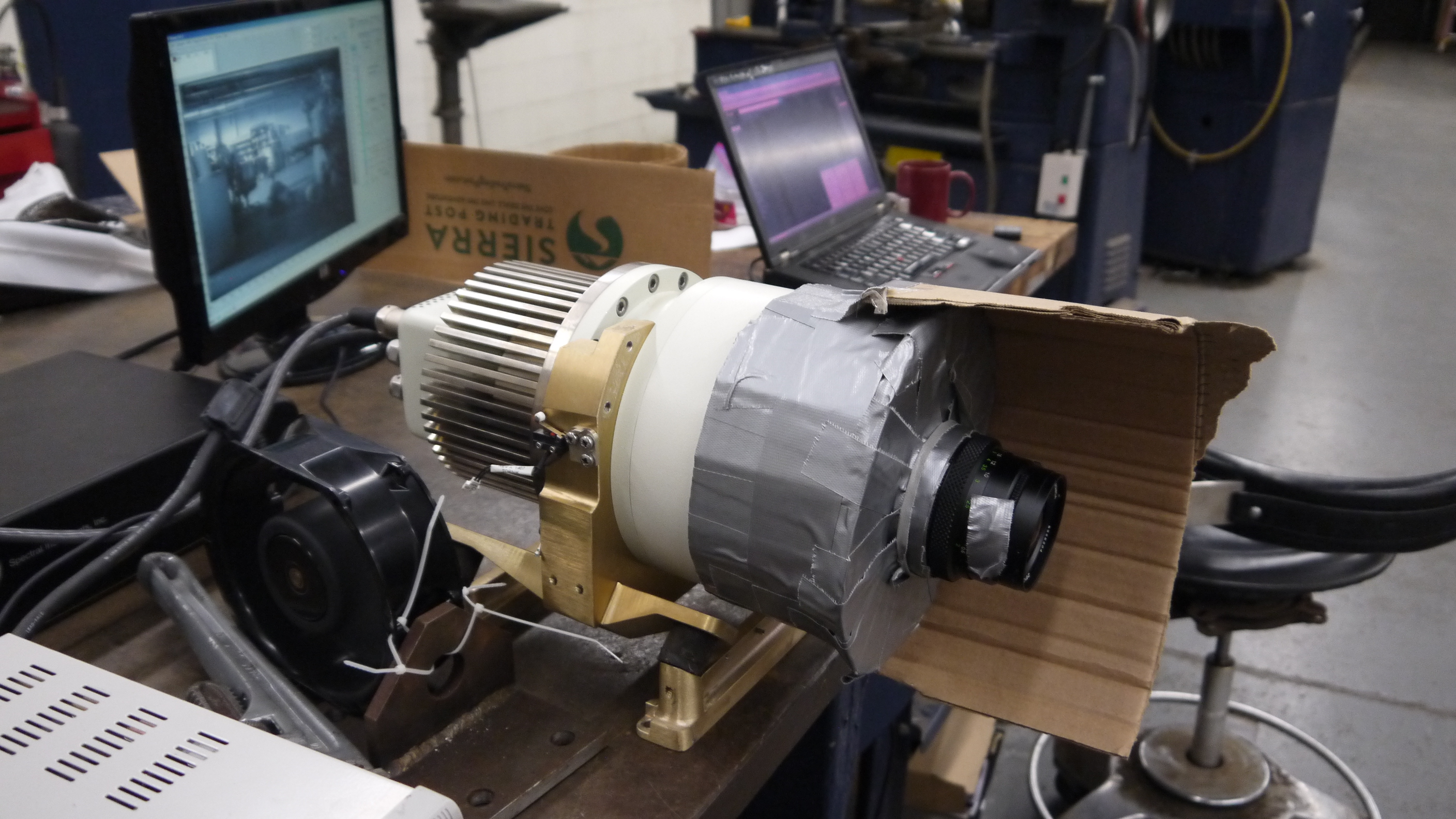

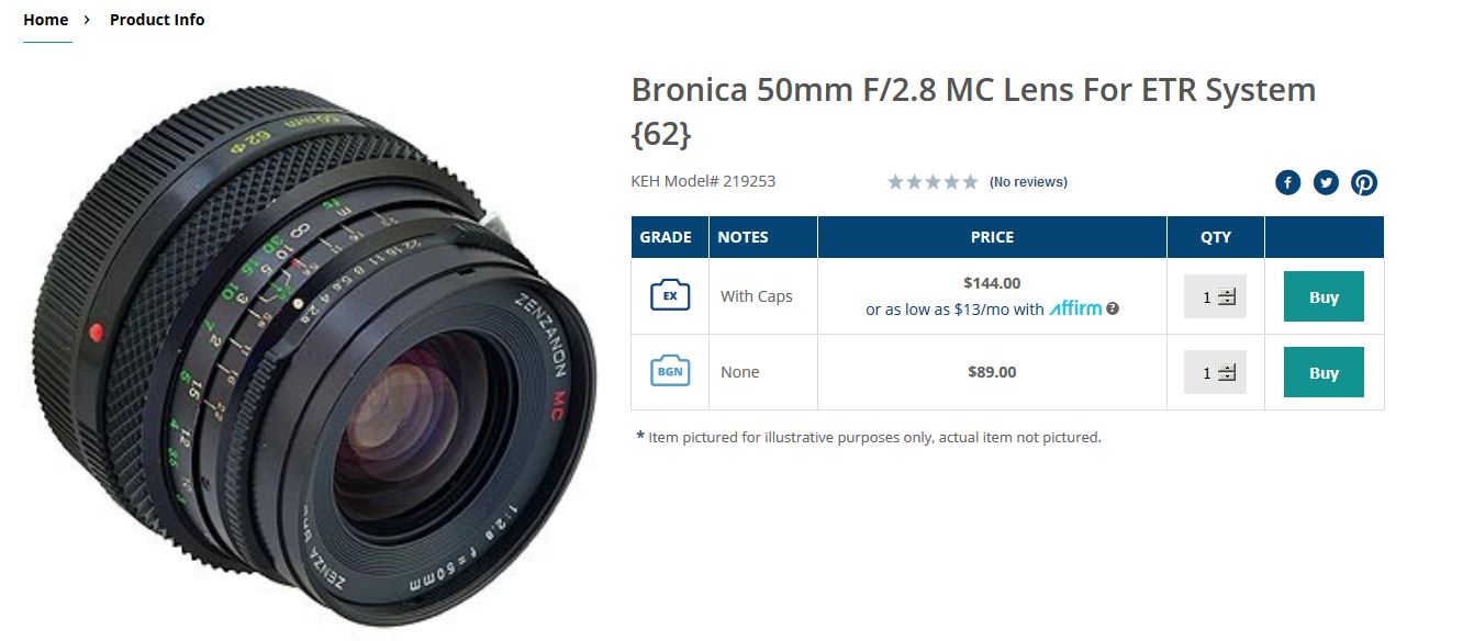
Wait, what is that optic?The sensor size (60mm x 60mm) really required a medium-format sized lens. I managed to get this lens from KEH for ~40$ and it seemed to do the trick quite well. Bronica is no longer in business so the lens's are generally lower-cost than their equivalent. There's a manual, lever-selectable aperture that moves the internal iris based on the selected f-stop. 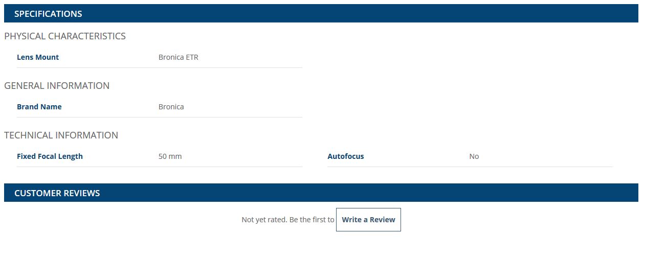
As I was not sure of the distance required for the optic from the surface of the camera + fiber assembly, I made a temporary cardboard optic mount, heavily relying on copious amounts of duct-tape. The external 'shroud' was just to prevent light from the screen from interfering with the images. The 'lens' assembly was not taped to the camera directly, instead it could slide on the outer-round surface of the camera's vacuum chamber, this really helped in adjusting the lens position. 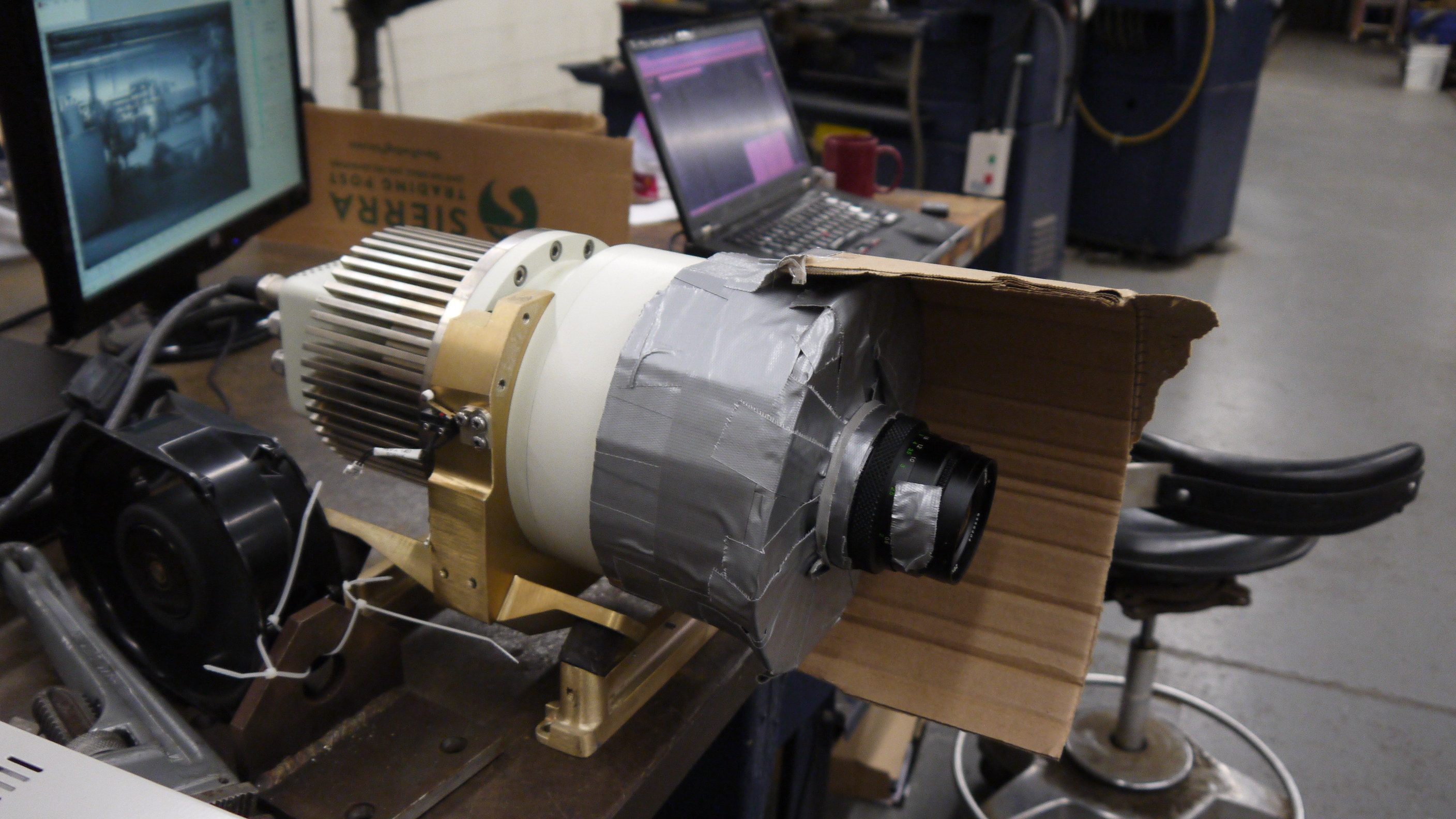
Progress! After tweaking with settings and optics here are the progression of images:Background image (shutter over optic). Note the sensor itself is read as four separate sensors, at the time of this writeup I did not have the calibration files to compensate out the edges. 
After playing with optics 
The noise was not Gaussian, it was elephant 
Screen shot of test software capture. This was the first 'legitimate' image that came from the camera 
GETTING CLOSER TO A REAL IMAGE 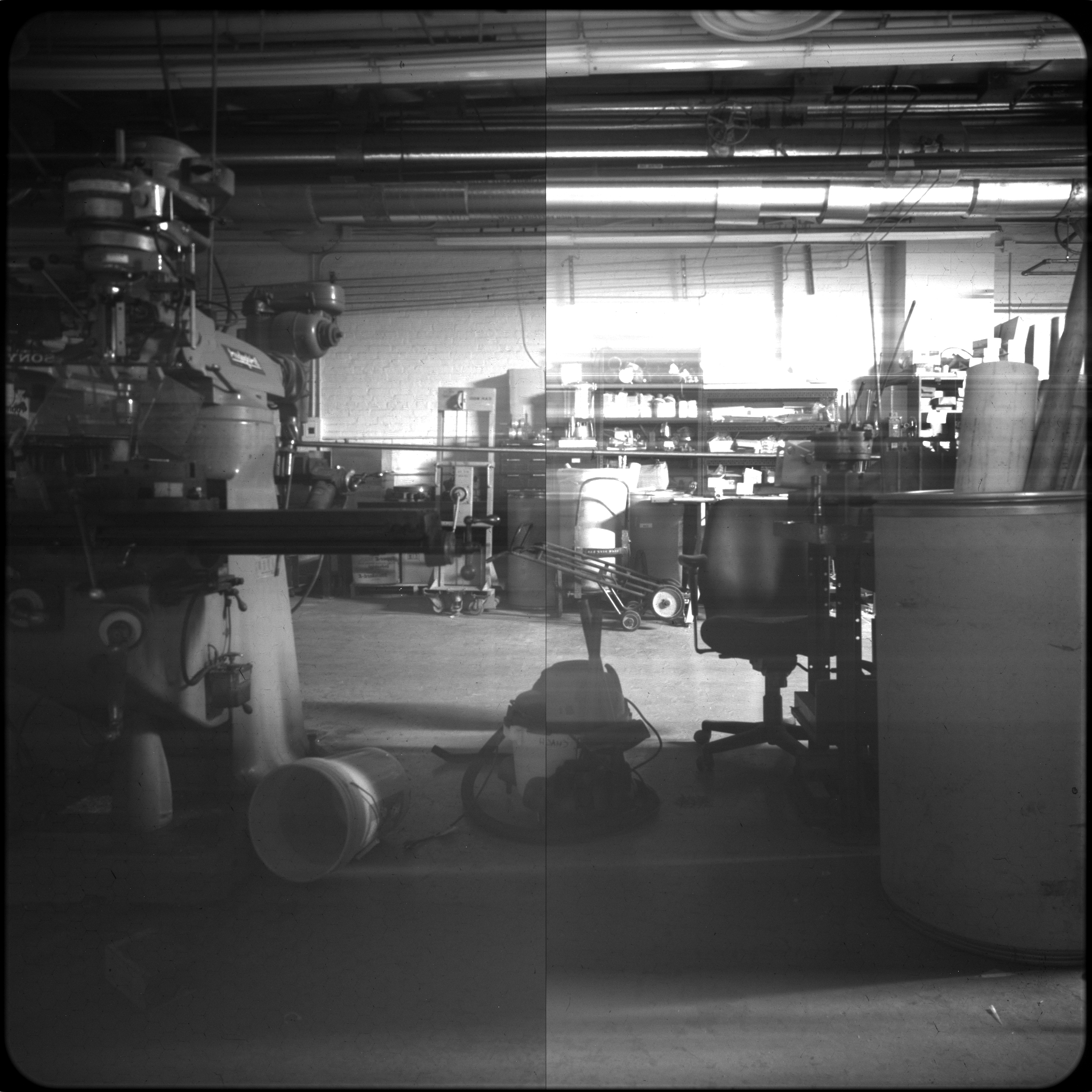
CLOSER 
CLOSER YET 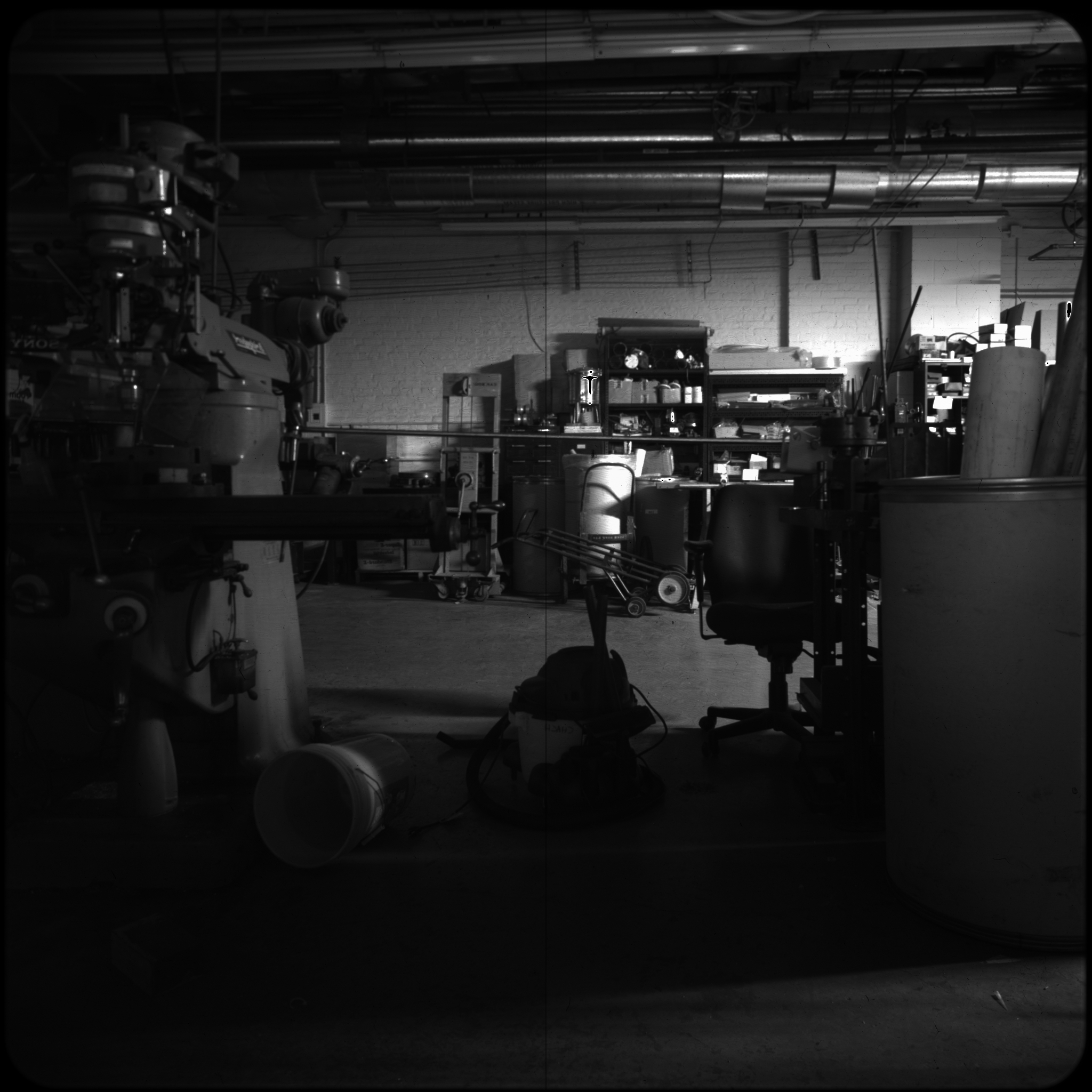
Rotated correctly now! THIS IS IT! 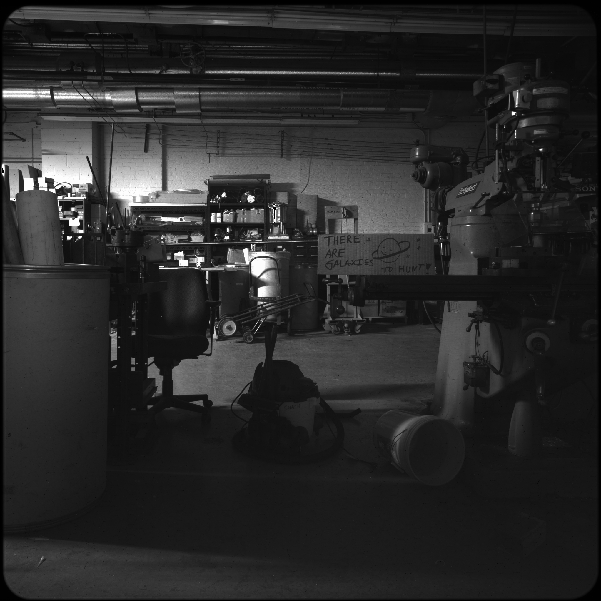
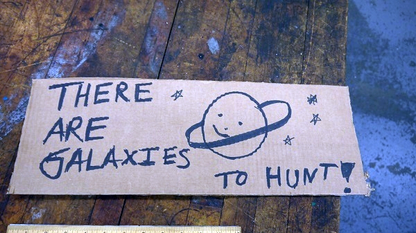
The shop, with actual lighting 
Here's the sign in particular I was gandering at. Yep, I got creative with the sharpie 
Concluding Remarks:
|