
Dane Kouttron
This project / write up is in progress, check back for more soon!
Project Documentation: 08/2026
PocketNc V2-10 Awakening and Upgrades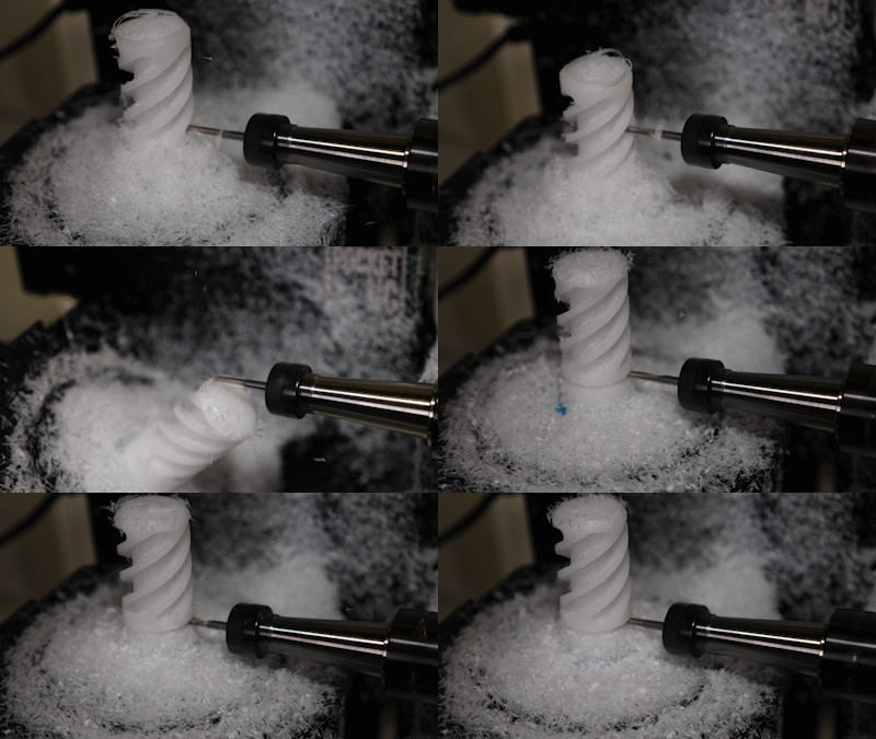
I spotted this amazing little cnc a decade ago at Makerfaire NYC, its now a mature product. Did you know all of the CNC parts on the OpenArm V1 / V2 are machine-able on the PocketNC? Lets wake up a super cute used 5axis, kit it out with a few upgrades, and put it to work. |
Some HistoryIn 2013, myself and a bunch of fellow MITERS compatriots headed down to NYC for the yearly Makerfaire. In 2013 these events were still quite new and featured small startups showing off their products and projects. There were highly questionable homemade FDM printers held together with rivets and some elaborate python scripts, automated carbon fiber weaving contraptions and even early acoustic Tesla coil kits (oneTesla). In between this sea of creativity was something that stood out, a very early mini 5 axis. Shown below it is ripping apart some green plastic with a tiny spindle as Jaguar Kristeller sits in a trance watching its intricate moves. This was early on enough a DB-25 parallel port is visible, one of the early indicators of LinuxCNC (formerly EMC2) running in the background. I think Michelle Hertel, one of the two PocketNC founders, is even in the last photo, showing off the hardware! 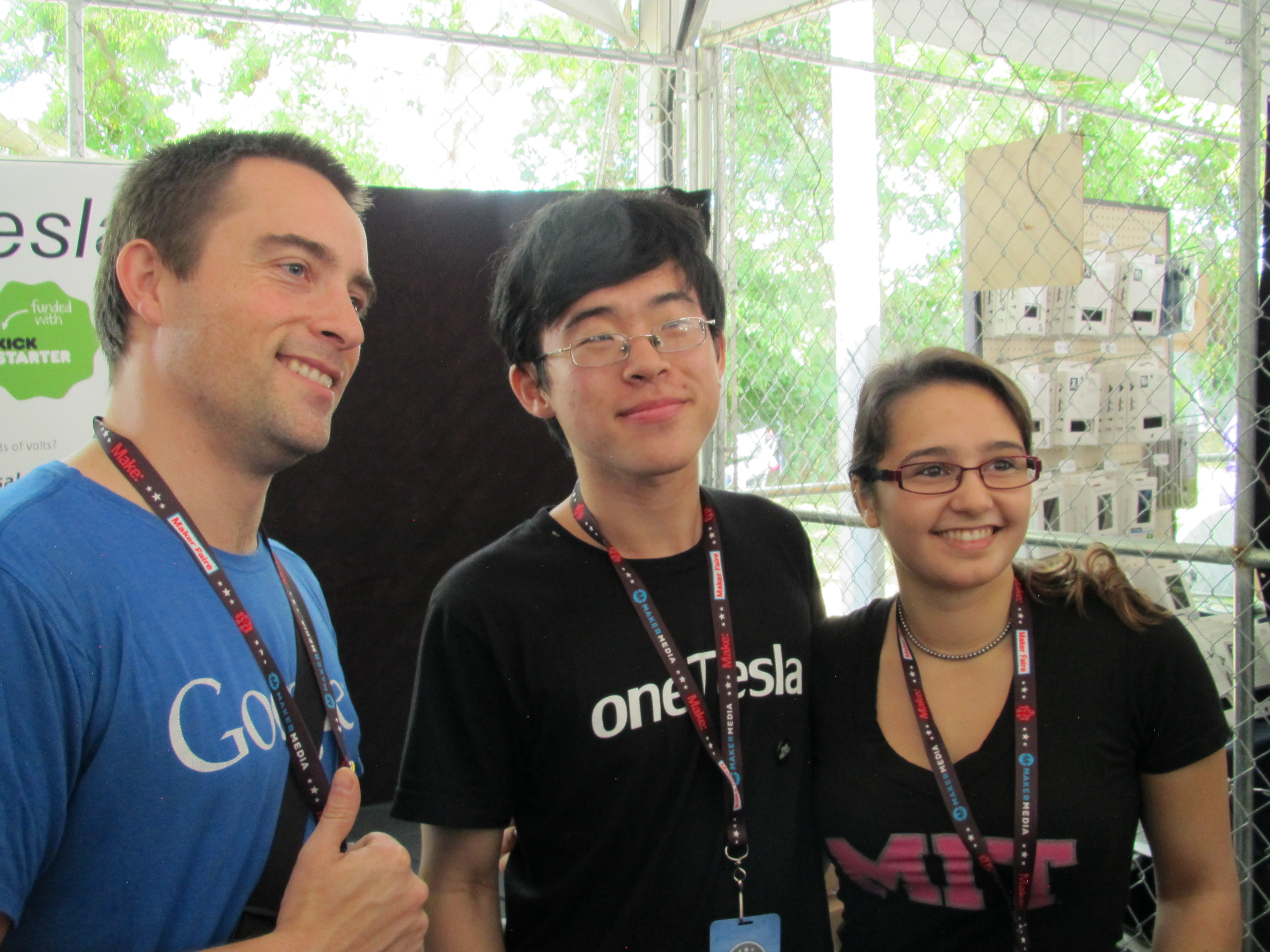
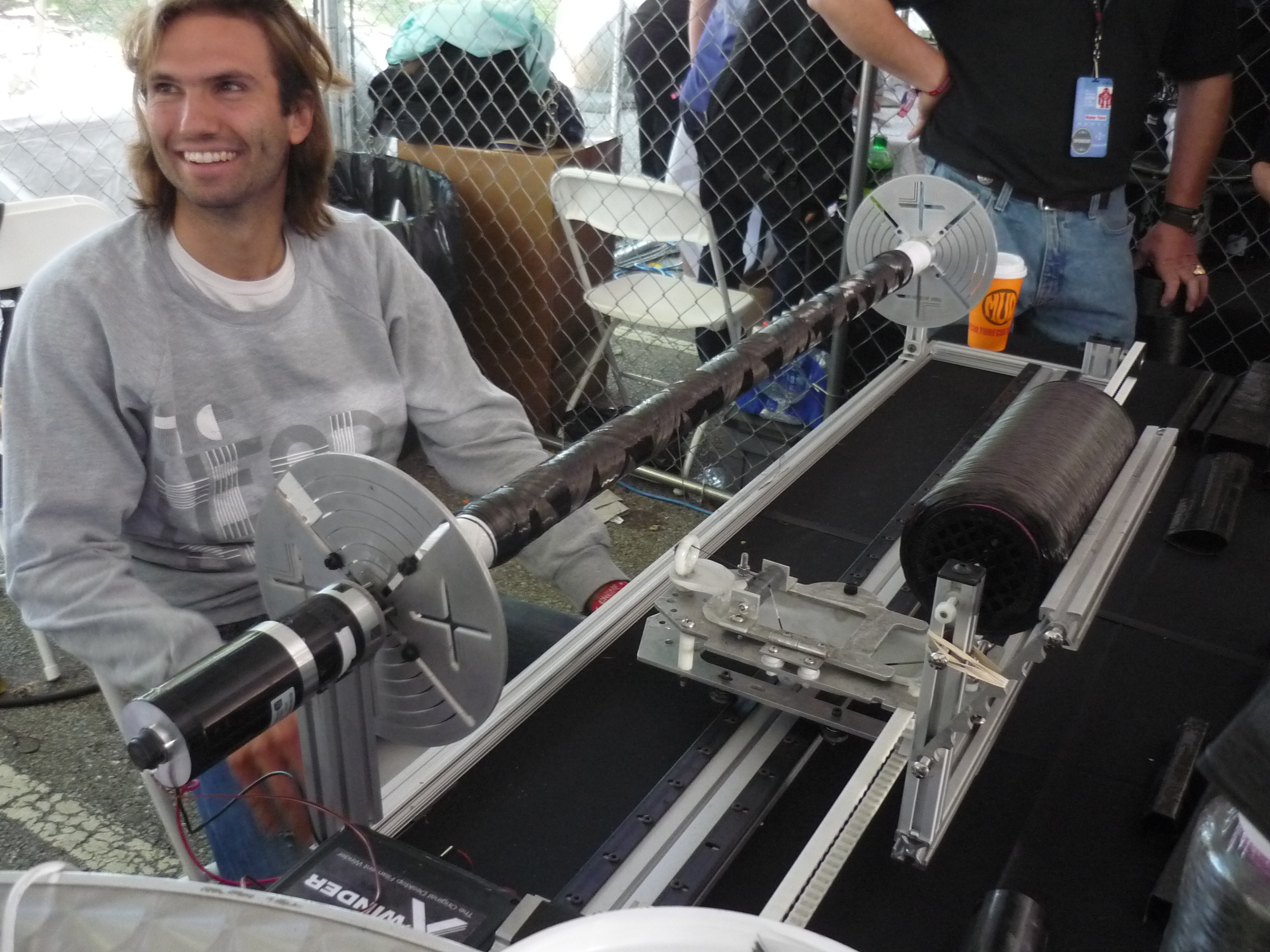
This was such a good period of time for hardware startups 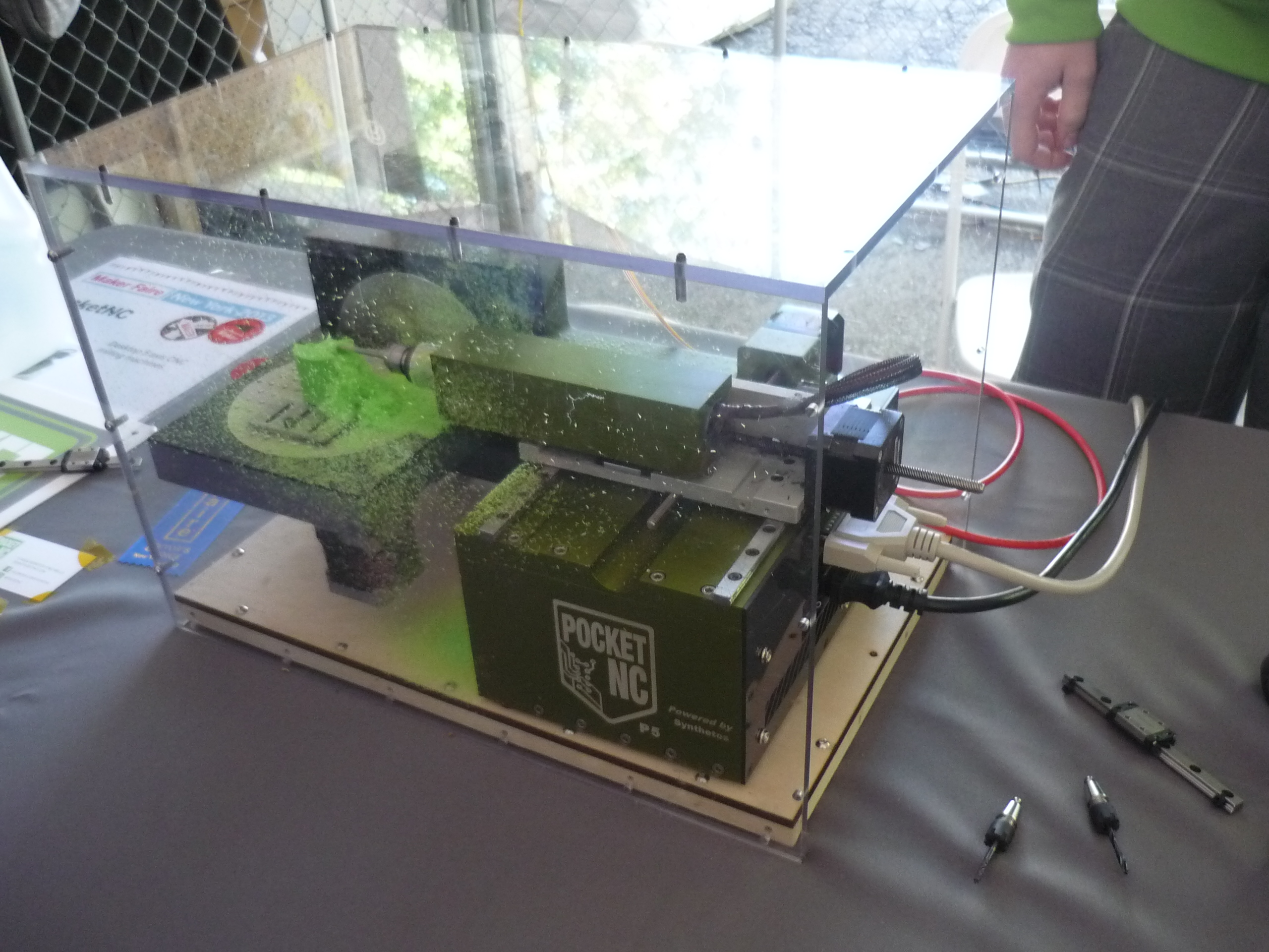
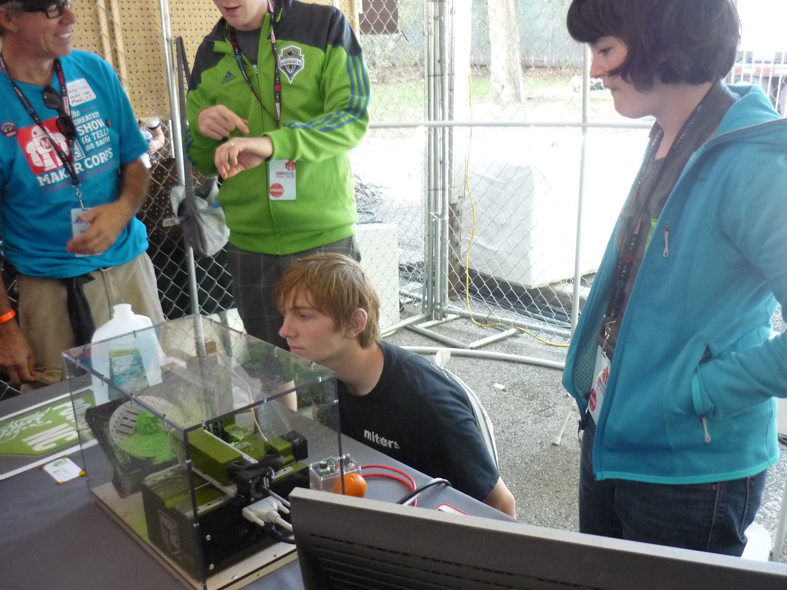
Pitching subtractive manufacturing during the rapidly growing era of FDM additive manufacturing seemed like it may be a hard sell, however they did an excellent job marketing this hardware to schools and academic institutions. The fact that they have been in business for over a decade is kind of a testament to that. Makerbot, one of the early vendors that brought FDM printing to the consumer, had not even released their "replicator" printer at this point, so 3D printing at this time was repraps and wooden Makerbot Cupcake printers. The PocketNC hardware has changed a lot from that early 2013 prototype, with the advent of smallish single board computers all of the controls were now contained inside the machine. It looks like they picked the beaglebone black and stuck with it. Finding a used machineTiming sometimes just works out. I spotted a mystery pocketnc for sale on the Penta machine forums, with no photos but a very communicative seller who seemed like a genuinely excellent person. With the combined efforts of two Birkel's, the CNC was picked up and shipped north. Thanks again for all the coordinating, meticulous packaging and help! 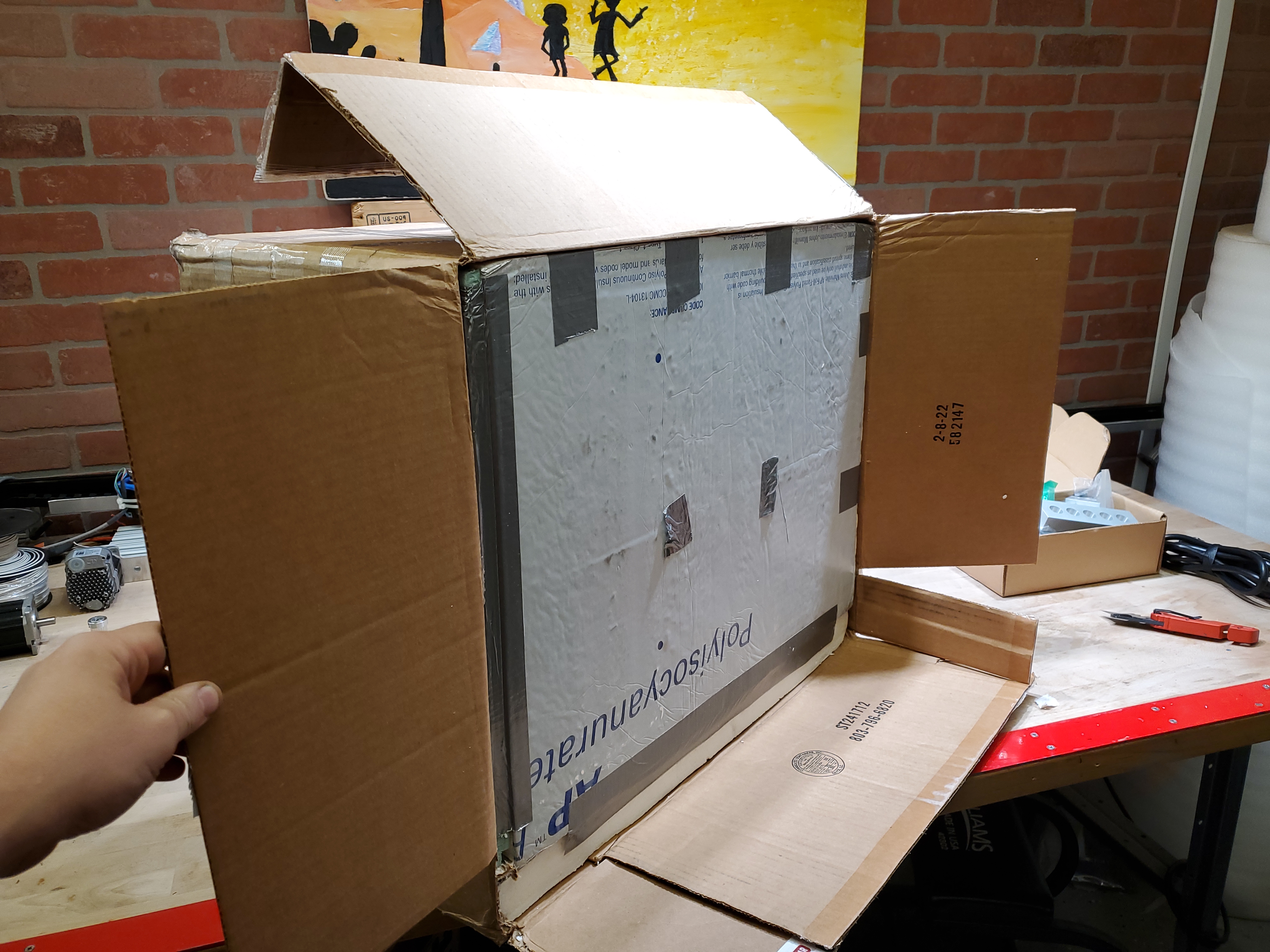
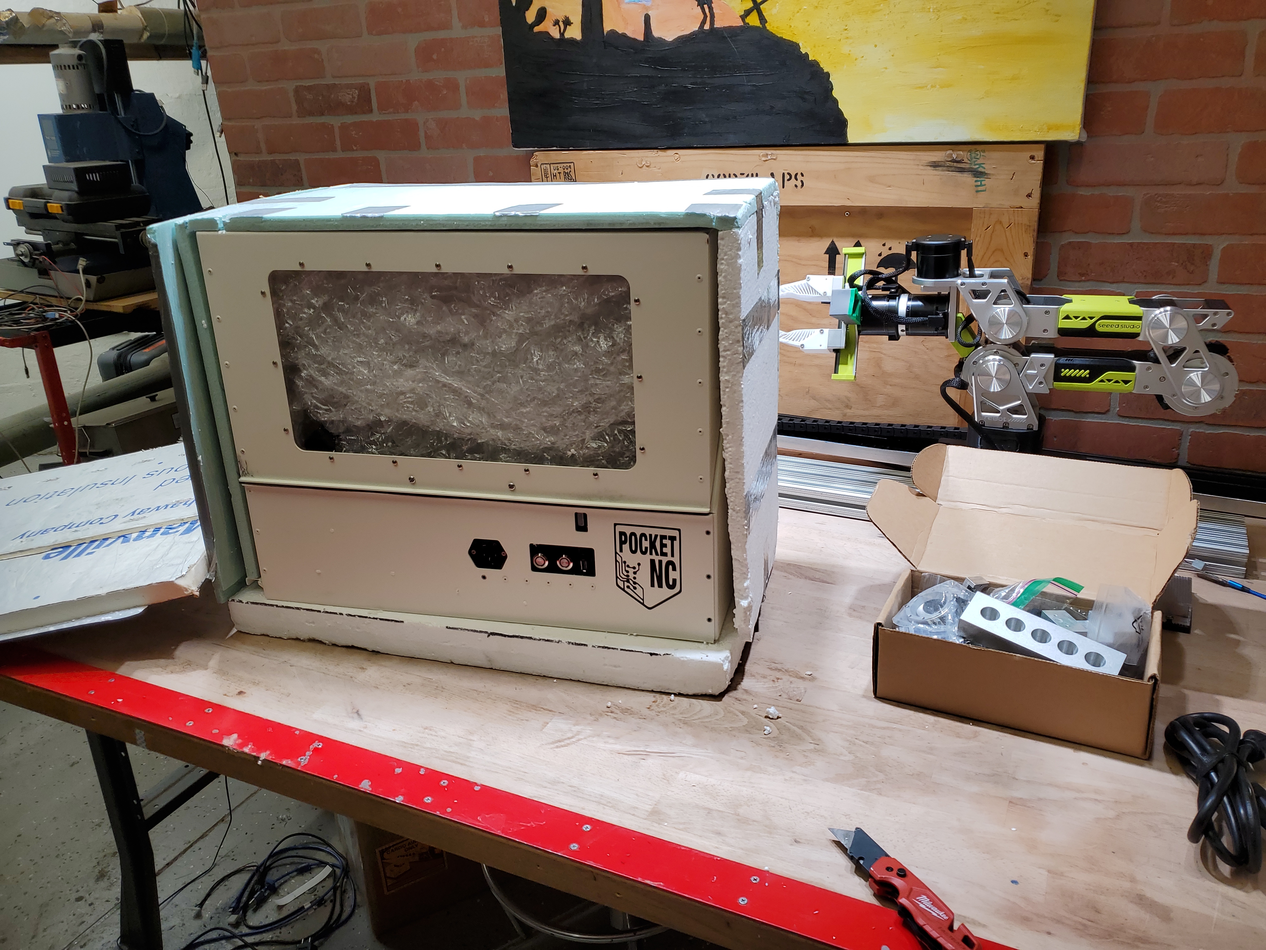
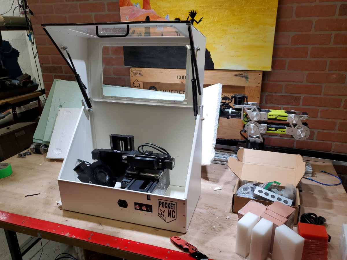
It was in amazing shape, curiously it was a quite early serial number, I'm fairly certain it's an early V2, 10k rpm spindle. In fact it turns out, after reaching out to Penta machine, this was the third pocketnc V2 shipped. 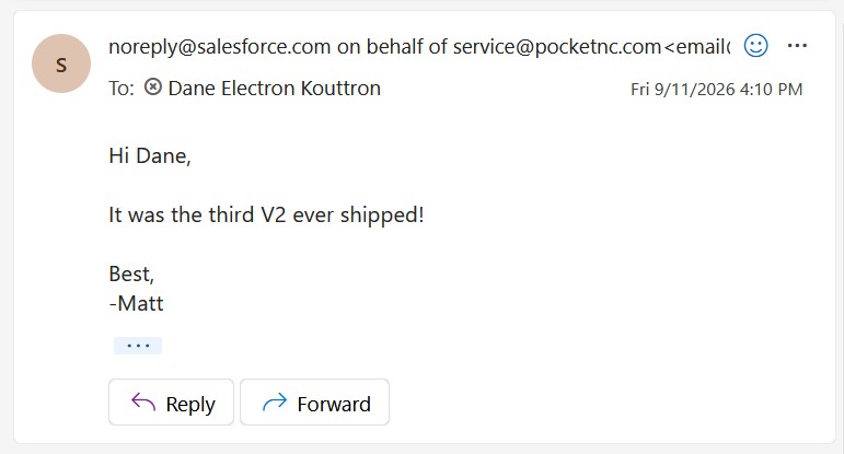
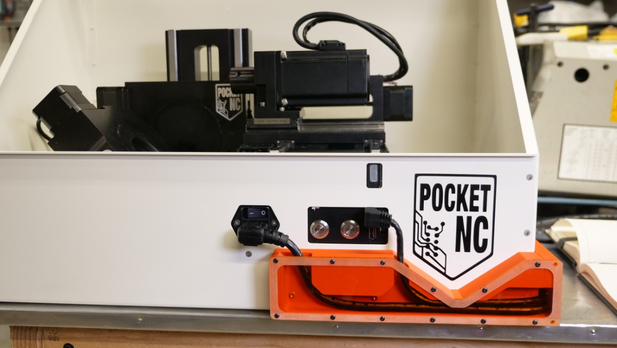
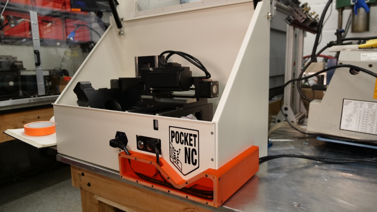
It looks like the V2-10 launched in late 2017, so this machine may be nearly 9 years old at the time of writing. Cable ManagementSomething I always found weird were the front-protruding cables. You'd need a network cable and an IEC plug flying out of the front of the machine. This does seem like something that can be a bit more contained fairly quickly with a large print. I modeled up the front case and wire protrusions, then used a photo to overlay features that would be difficult to grab otherwise. A right-angle IEC cable and right-angle cat 6 Ethernet cable both exit the machine and then are captured into a 3D printed channel. That channel wraps around the case such that the cables exit the back. I didn't want to drill into the case for this mount, but fortunately the whole enclosure is sheet steel, so strong magnet mounts are a very promising option. Both print files are intended to fit on a conventional FDM printer and are attached with two M3 screws. Thermal inserts are used in the FDM parts to attach the cover plate as well as the side wire routing print. Initially i went with a translucent red laser cut plate to act like the front of the cable routing cover, and then later opted for an opaque two-color ABS cover. 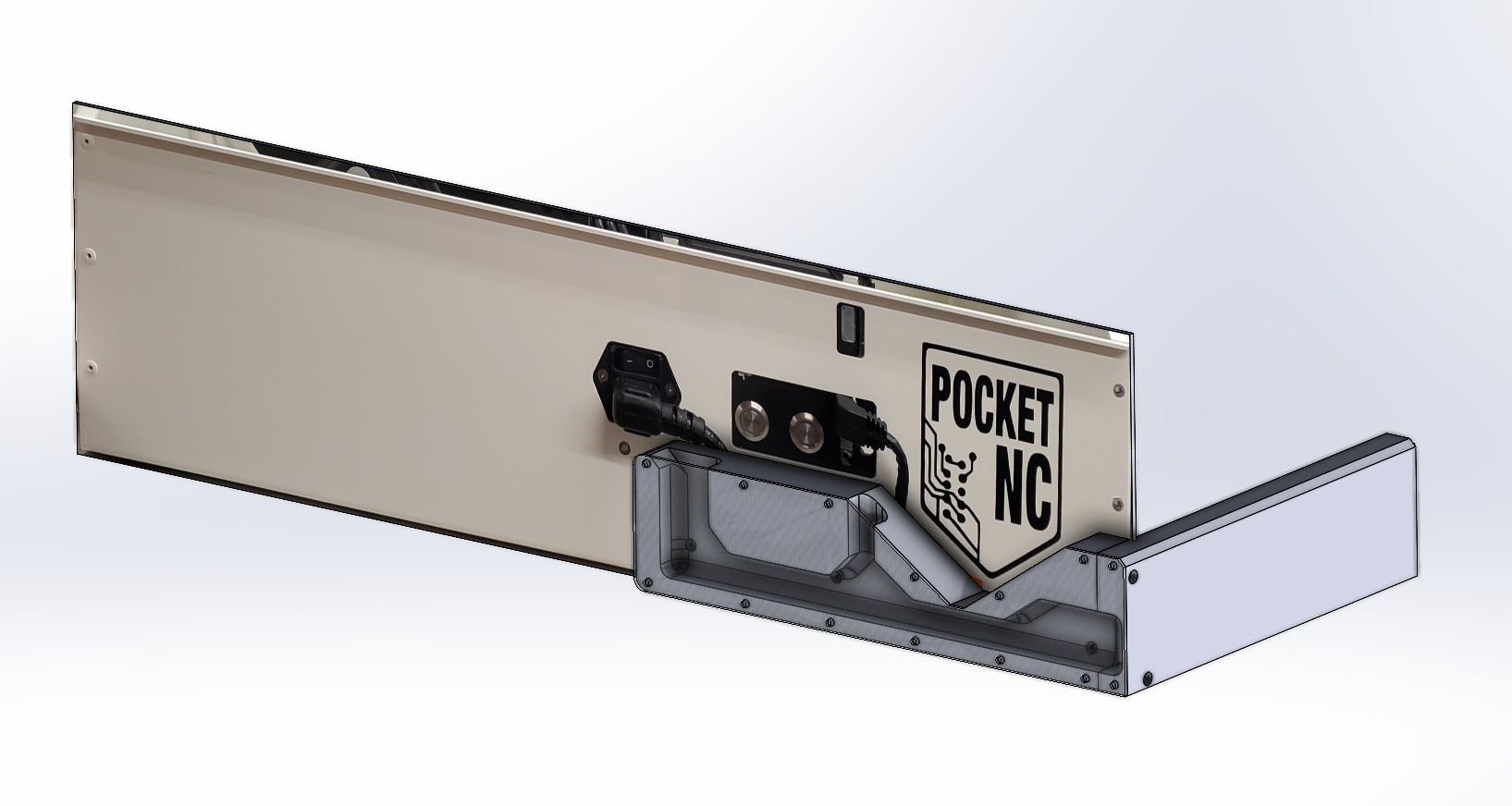
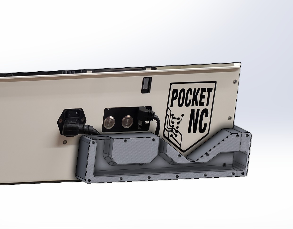
The two printed parts that make up the front have rear facing magnets, attached with small threaded inserts, and an array of front threaded inserts to attach a coverplate. These two attach together with, you guessed it, thermal inserts and some 25mm M3 machine screws. 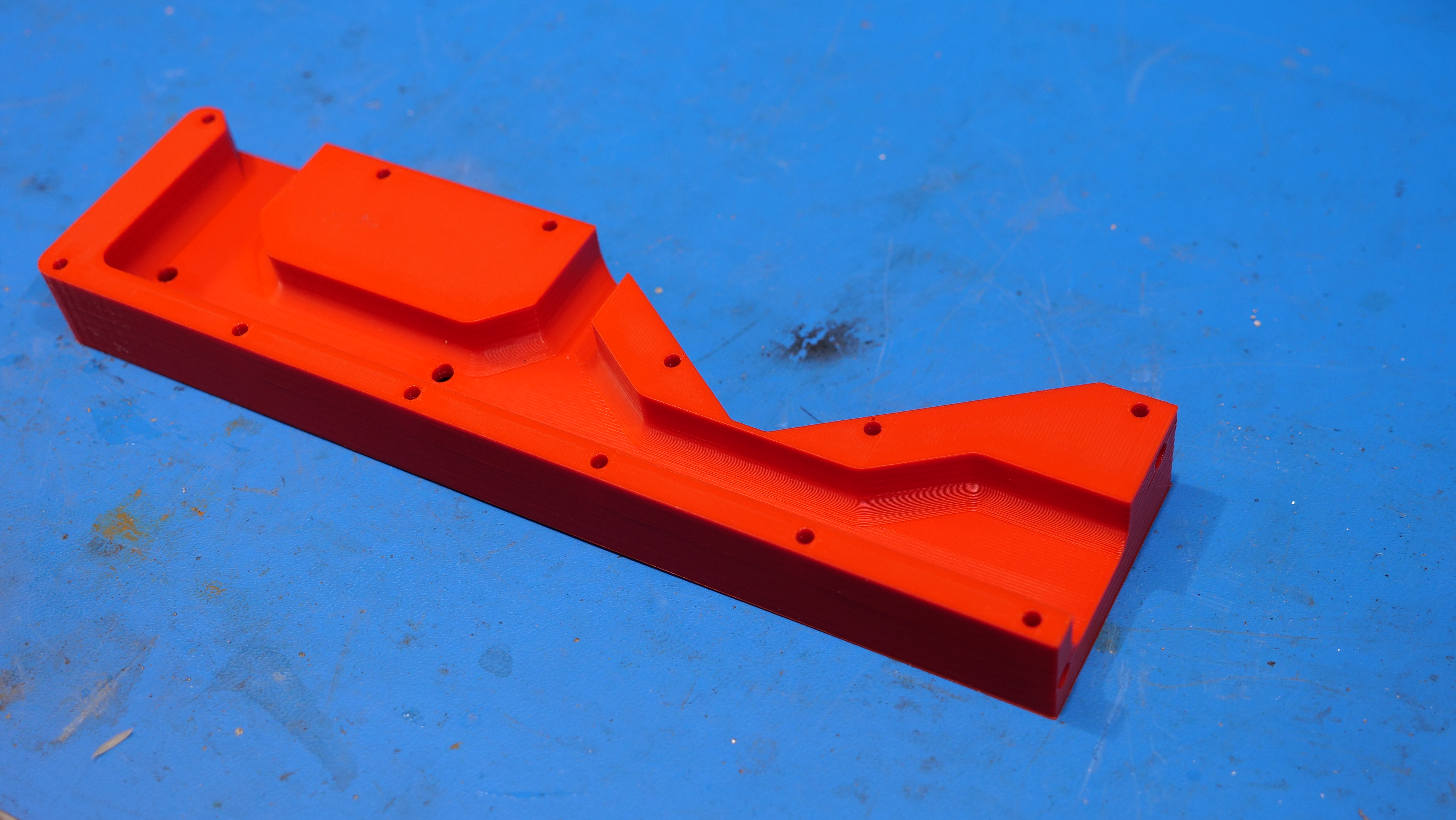
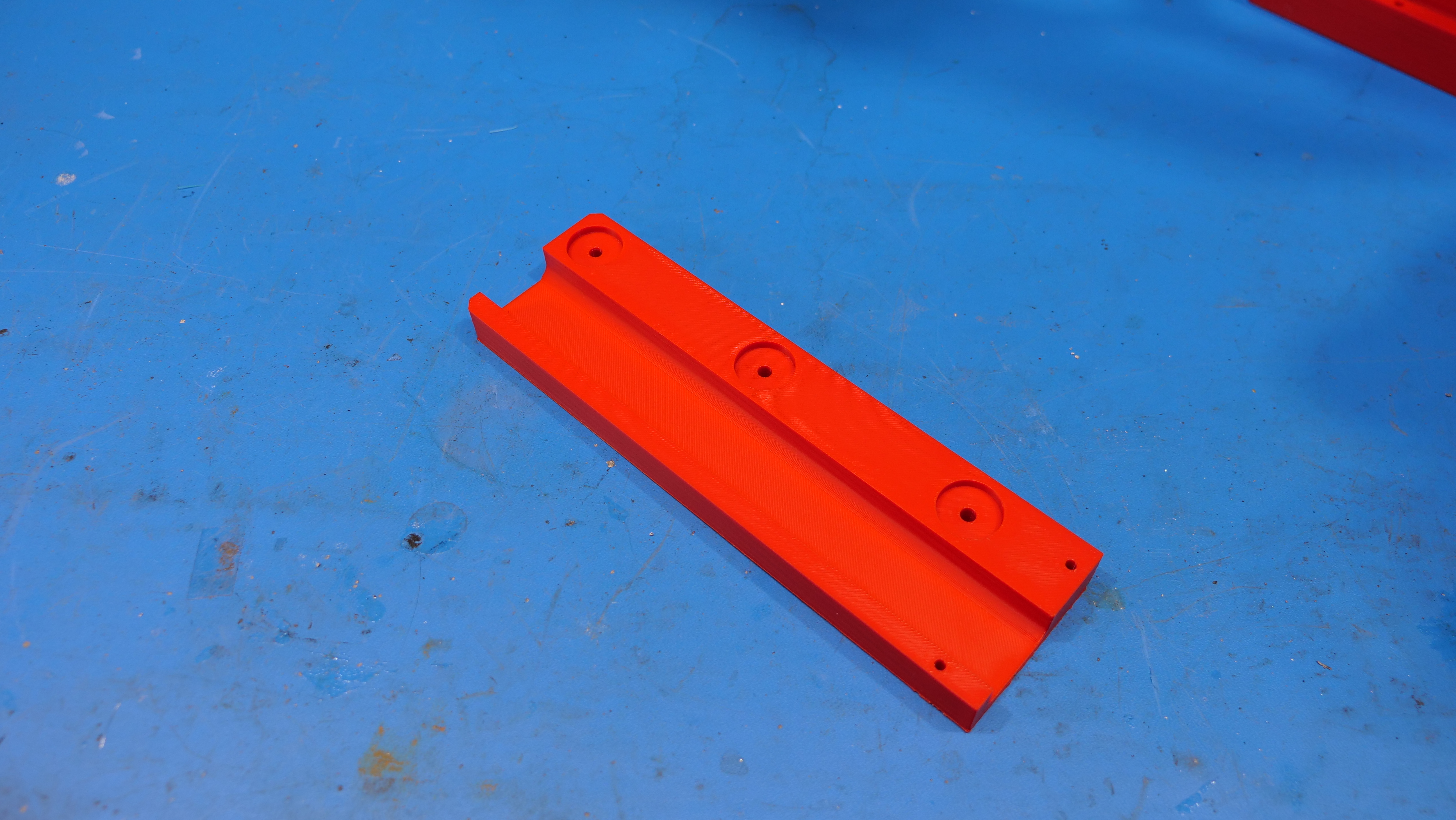
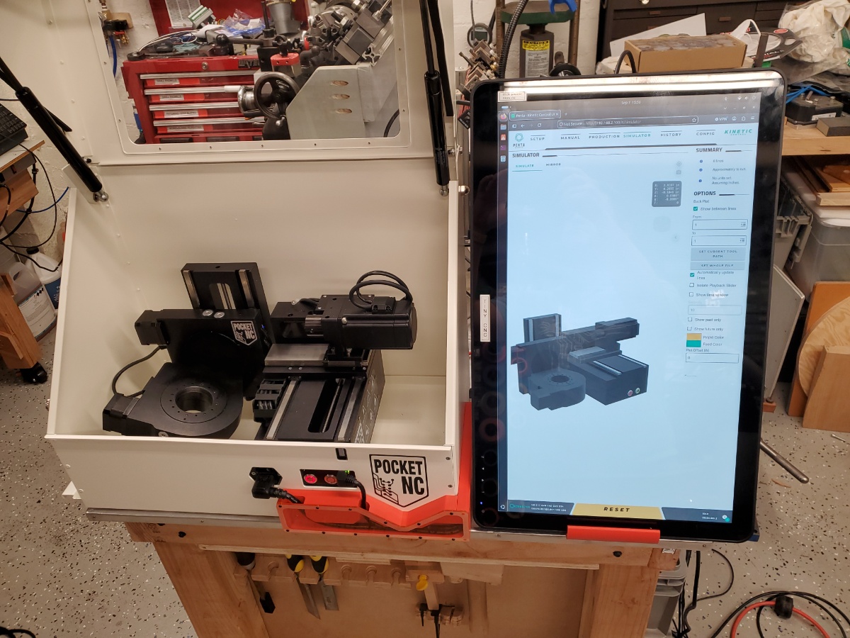
With the prints complete, lets quickly assemble this wire-guide. The first step is to install the array of thermal inserts. These are intentionally all M3, using this specific thermal insert [Link]. I still use the "put the insert on a screw and heat with a torch" approach, but I did just get in a portable thermal insert tool and will give that a go on some upcoming projects. With the inserts in place, time to attach the magnets, connect the two and route some cables and attach the whole assembly to the case. Its always nice when something just fits. The number of magnets may be a bit overkill, the resounding 'clunk' when this mated to the case was impressive. I did opt for some specific cables for this assembly, I highlighted them in the image below. For the right angle Ethernet cable I opted for a 10' right angle cable from Cable Matters [Link], and for the right angle IEC cable, i opted for "P006-006-13LA" from Tripp Lite [Link] Overall this worked out quite well, it wasn't necessary to run the side print the full length as the cables would end up out the back and then down a table either way. The clear cover was temporary, a laser-cut multi-color plate would do a great job as well. Display ComputerI went a bit overboard with the display computer for this project. Initially I was hoping to host a copy of Solidworks and have the pre-configured slicing settings available on a windows Intel Nuc computer, however, at the moment a modern NUC is the price of a 5 year old Toyota Corolla, so instead we're going to opt to just host the control display webpage and use some spare cycles to record video directly from the CNC spindle. The NUC of choice is a lab clean-out deluxe, model nuc11atkc4 supplemented with 32 GB of DDR4 ram and a somewhat modern NVME SSD. This is a 4 core basic system released in early 2022. For a touchscreen monitor I was opting for price versus resolution. Nominally 1080p is completely sufficient for simple touchscreen tasks. The plan was simple, a monitor + nuc would sit in portrait orientation right next to the pocketnc displaying the browser control page. 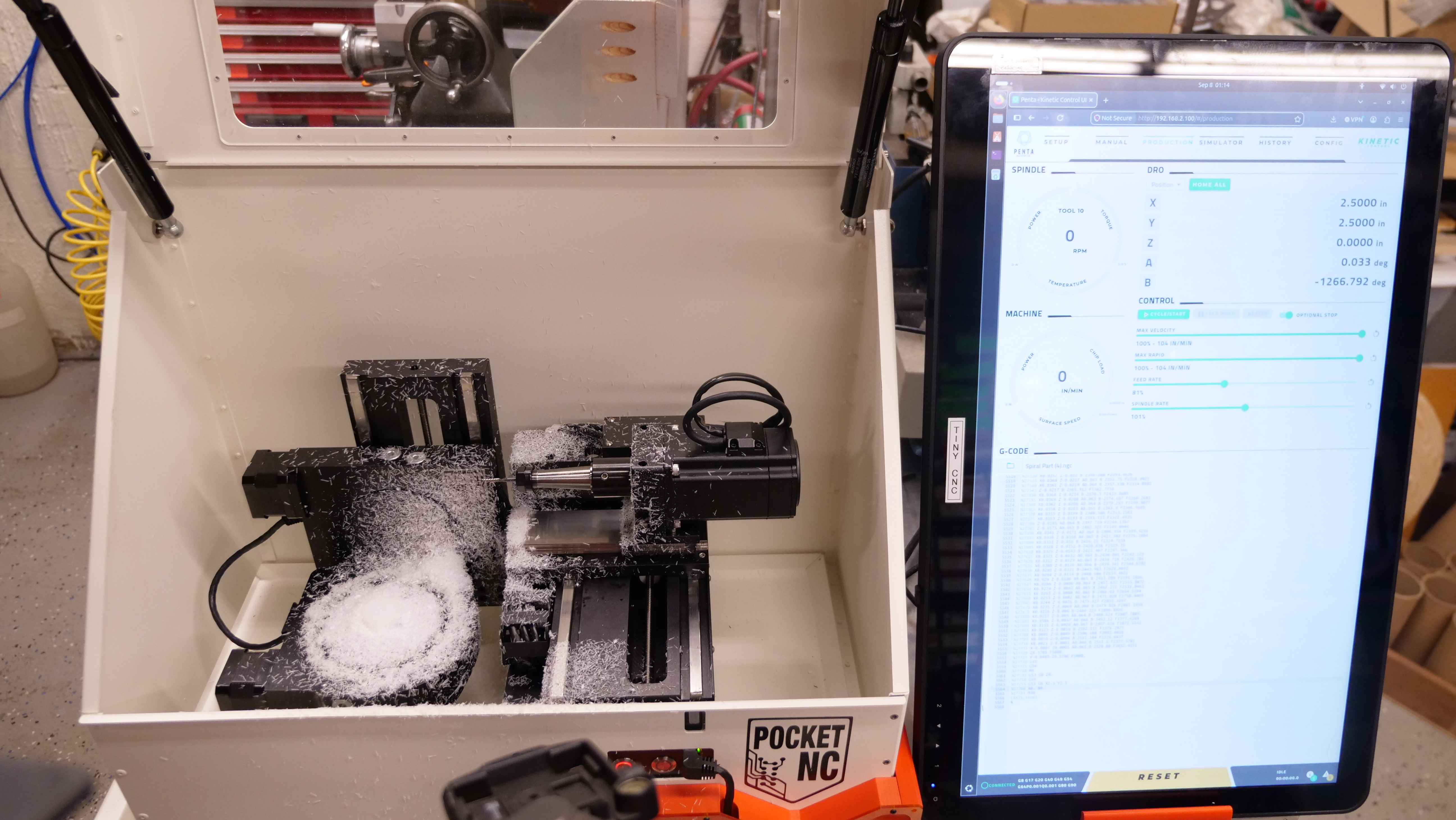
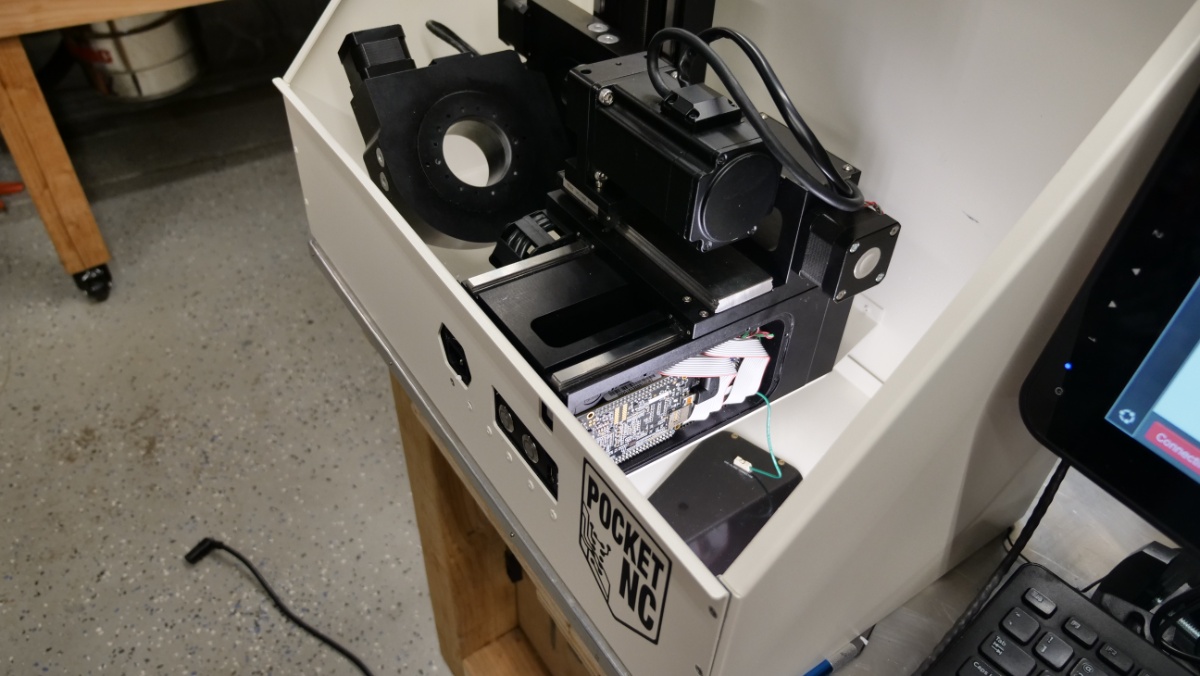
Curiously this became a bit of a small project on its own. My initial plan was a budget monitor arm from Amazon, however, the more i tried using it the less i liked how it operated. You do somewhat want the control monitor to be a static surface, such that it does not deflect when depressed. I tried locking down the monitor adjustment clamps but with only one point of contact and a somewhat large surface it really wasnt working out. Finally with the extrusion, print and monitor mount complete, here's the new assembly. Next up is to mount the NUC and monitor power supply to the extrusion. Bootloader RepairThe pocketnc internally is linuxcnc, running on a Beaglebone Black on the onboard emmc, with a shield that routes GPIO's to stepper drives, limit switches and other inputs. There are two user interface options for the pocketnc, a very simple web-ui, and a remarkably polished 'kinetic control' web-ui that is remarkably well done. My machine is old, so lets update it to the modern 'kinetic control', which is a purchasable add-on. 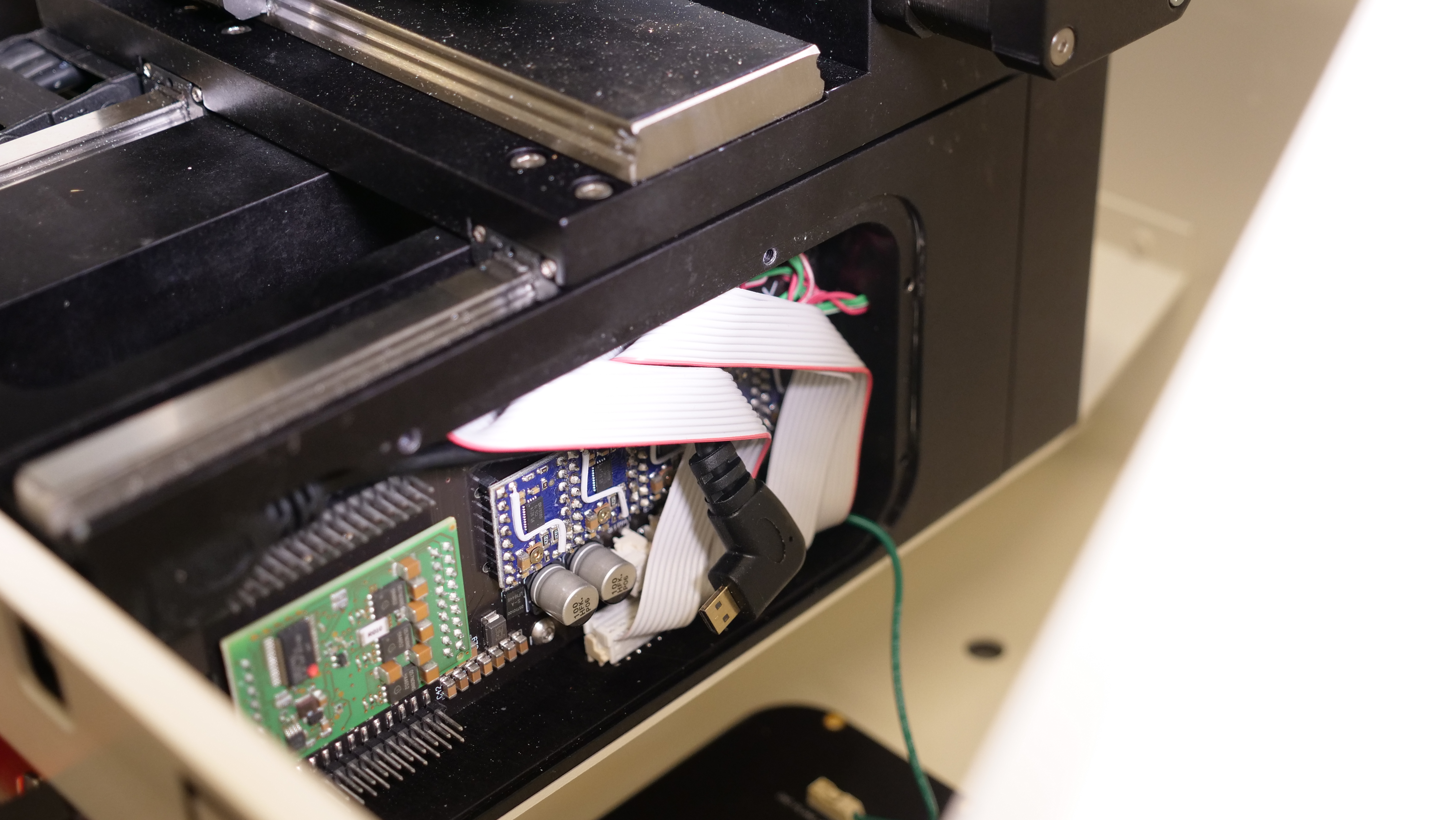
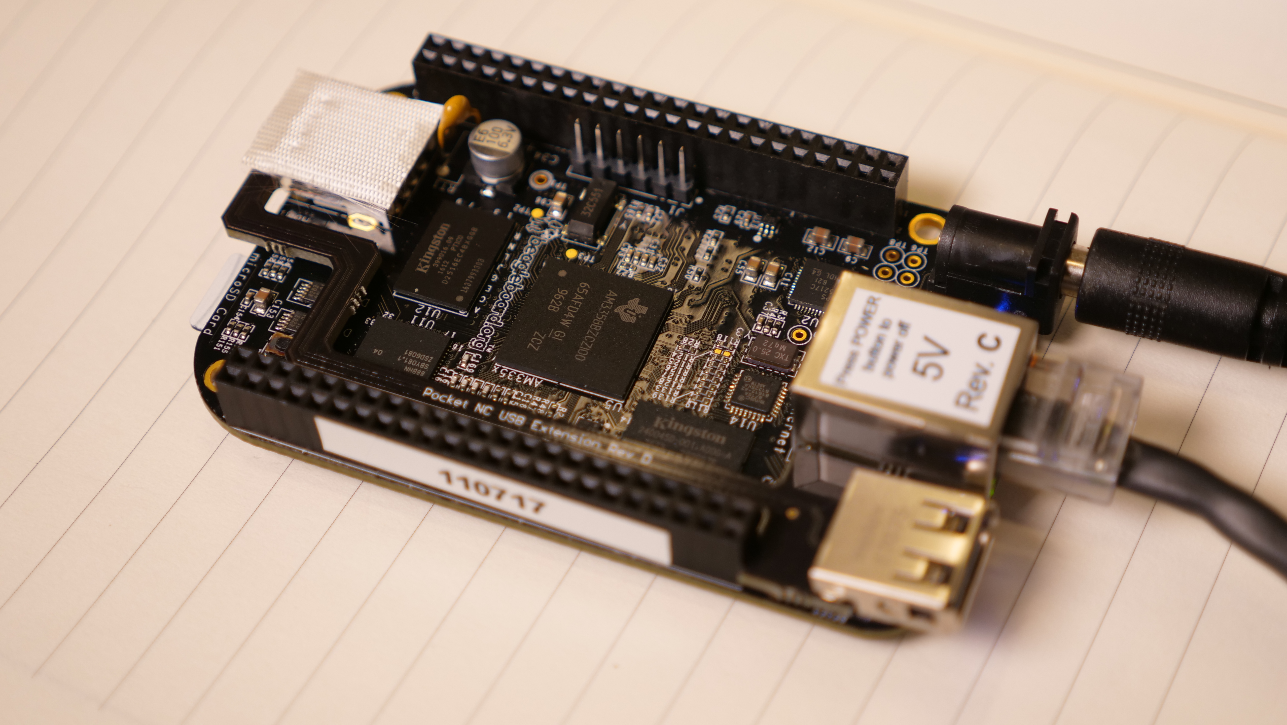
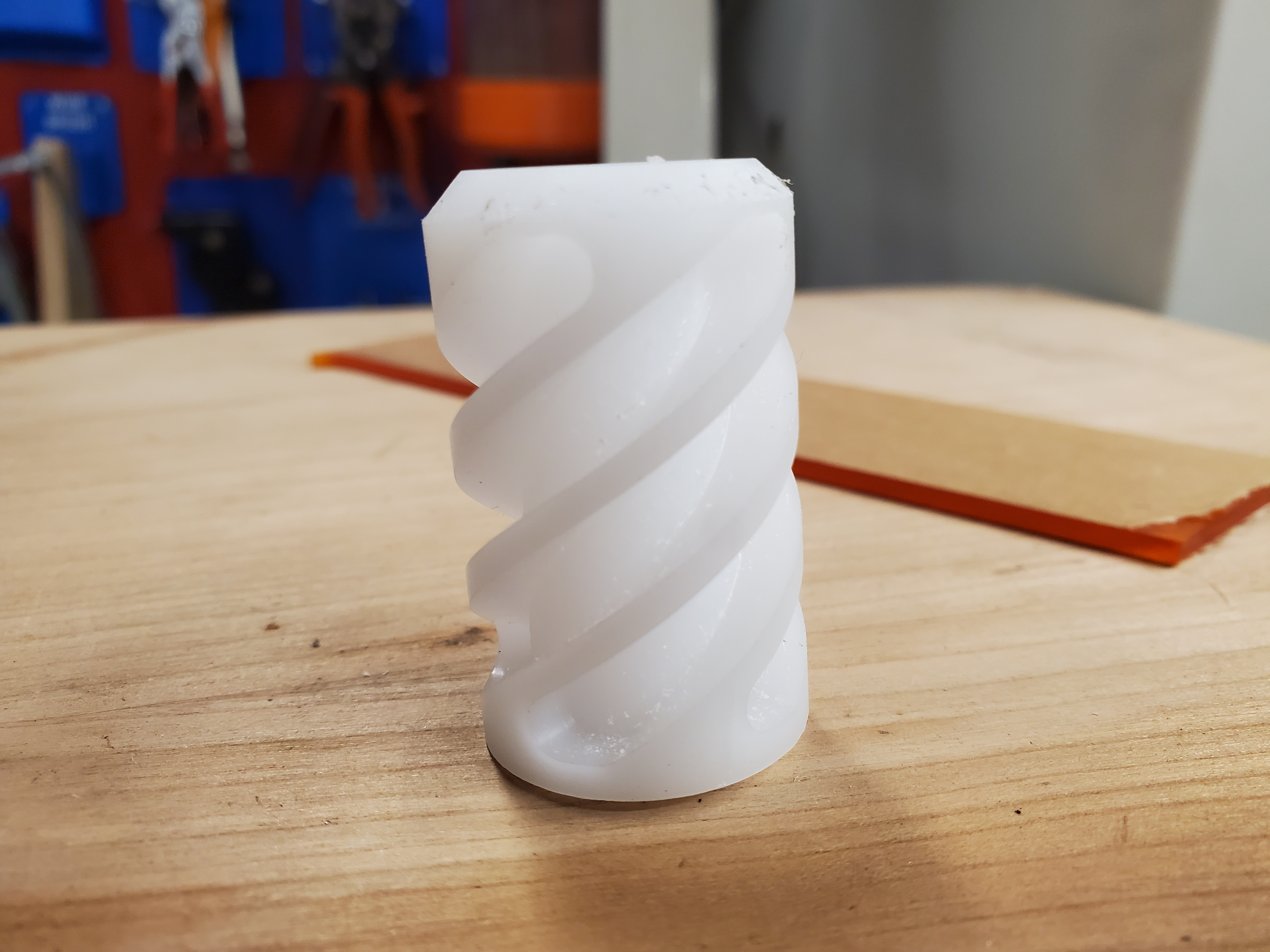
The upgrade to kinetic control is provided via SD card. Normally the bootloader wakes up, reads from the onboard emmc and fires up the basic webui. With the kinetic control micro-sd card installed, it should boot, check that there's an SD card installed and opt to run from the microsd. This does change based on machine bootloader version. For the older bootloaders, the process is, hold down the beaglebone onboard button for 20 seconds and it should now boot to the installed SD card. It should also re-write the bootloader order to check the SD card first. For me, holding down the button only permitted that particular boot to get to boot to the SD card and launch kinetic control. I had an inkling that this was a case of very early bootloader so I got to work. I started by running lsblk to see what I was working with and then trying the simplest route, tell the bootloader to try the SD card first. To do this I opened /boot/uEnv.txt which should tell U-boot where the kernel is located. In an ideal world i just pass along the location and this process is over. On subsequent boot, nothing changed and the SD card was not used as the boot device. Time to dig a bit further. Lets boot into the kinetic control SD card and then see what is going on. To do this I held down the S2 boot button on the beaglebone black during boot with the SD card inserted. running mount | grep ' / ' and then uname -r should report /dev/mmcblk0p1 on / and a kernel like 4.14.x-ti-rt or 4.19.x-ti-rt Here's what happened: This is good news, it booted to a modern kernel. If it had reported back something like: /dev/mmcblk1p2 or 3.8-1-xenomai we would very much be stuck back in the legacy version. Finally: And with that First CutsWith the bootloader repairs complete, and the clock running quickly into the next day, it was time to do some test cuts. The de-facto test cut is the pre-genearated gcode spiral from pentamachines, which uses a known cutter and 1" acetal rod stock. While i had the rod stock on hand, I did not have the ER40 1" collet. I looked everywhere, and finally accepted my fate, you wouldnt download a collet would you? Yes, thats exactly what I did. 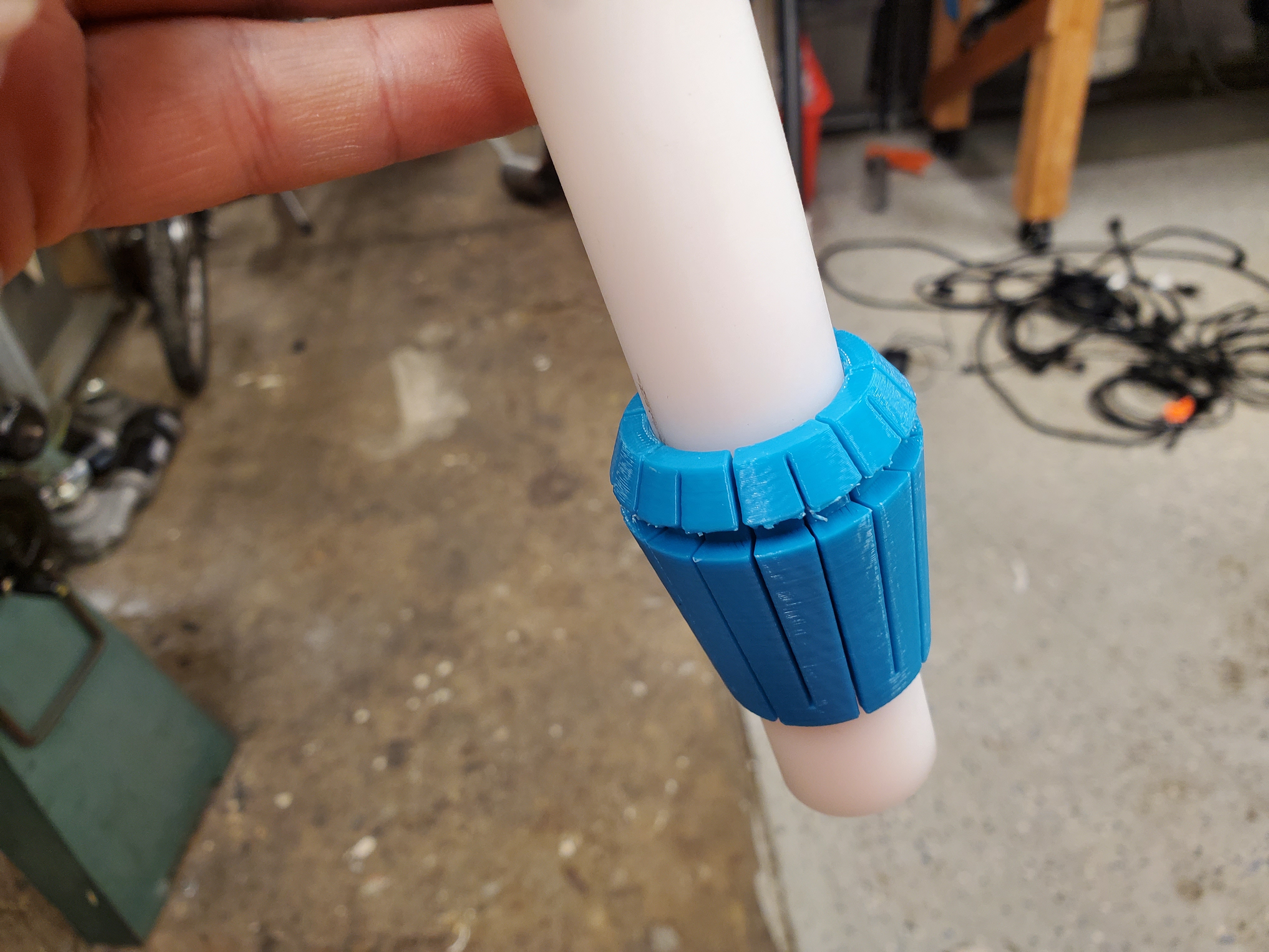
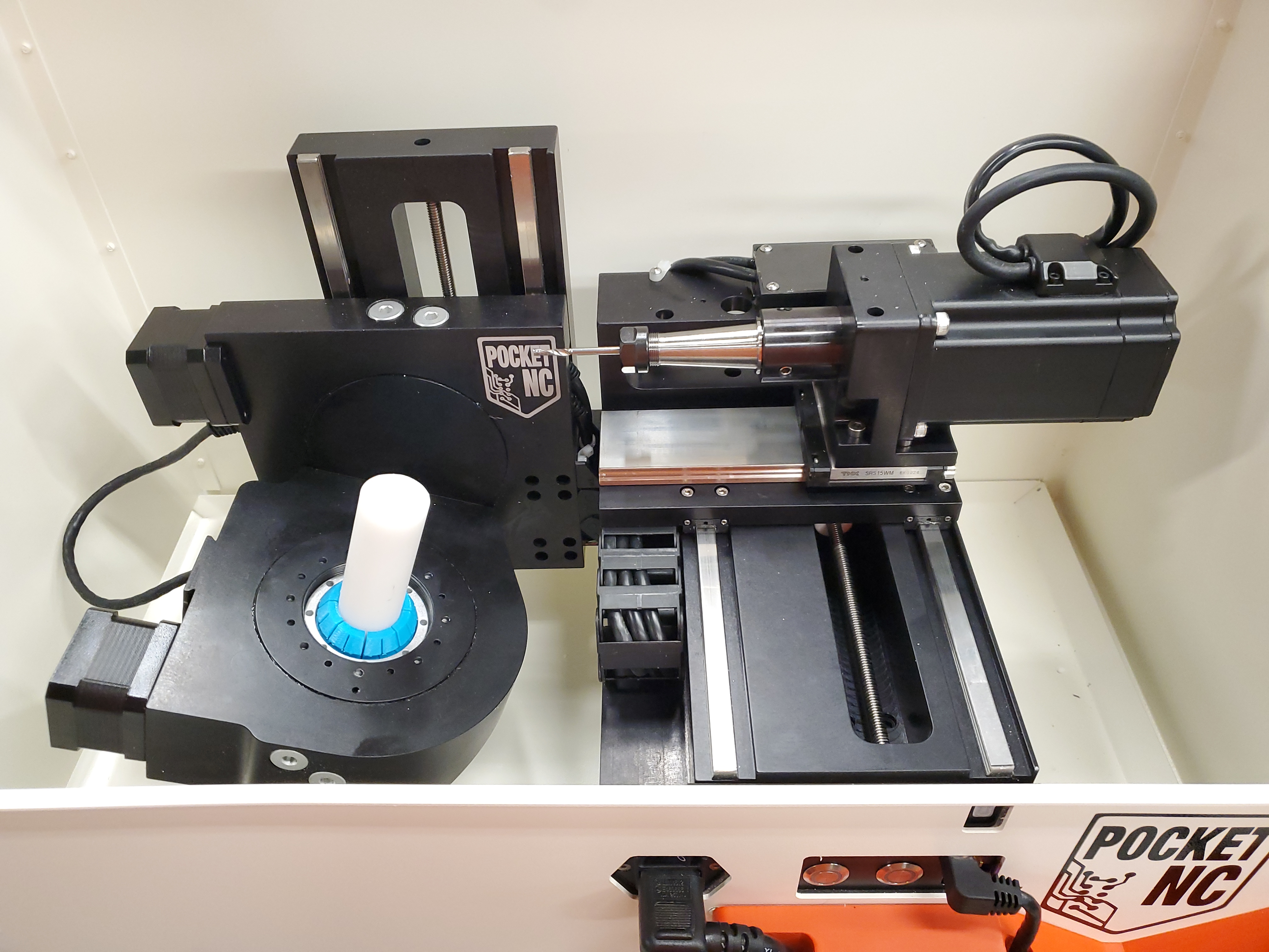
With the axis offsets guess-and-checked in place, it was time for the first cut. There was a small amount of A-axis offset, but it worked out! The part looked great! Acetal is such a great material to work with. 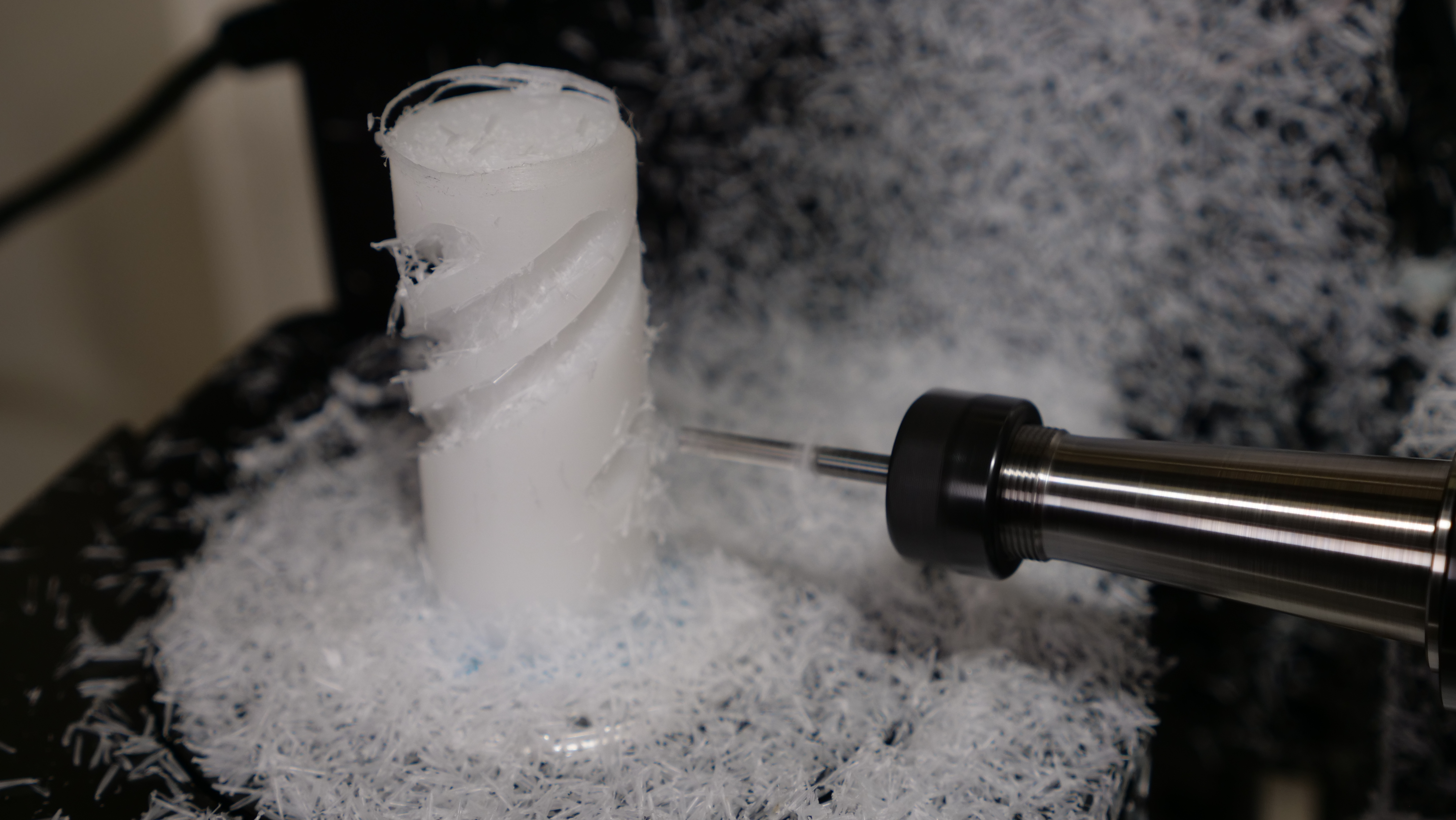
Budget Friendly Faceplate ViceYou have a very fixed work volume, so its best to use that work space as best as possible. Its very easy to chew up the work volume just with a self-centering vice. One way to keep as much work-space as possible is to use a surface plate. A surface plate can be as simple as a flat surface that the target part is glued to. super glue work-holding is a very established topology, especially for non-coolant environments. One thing I wanted to tackle was a somewhat consumable faceplate. If you run your endmill into the faceplate it should not be the end of the world. I had initially looked into CNC-ing these faceplate assemblies out of billet stock, however the materials prices became fairly high for a consumable. To get around this I opted for a two part assembly, water jet 1/4" 6061 stock is very cheap, and round standoffs with internal threads are also remarkably affordable. With the two parts and a simple countersunk machine screw that's really it. The only real expensive part is a 1/2" ER40 collet. This gets you as close as possible to the A/B axis. Working in 2D is so much more budget friendly versus working in 3D. I started by waterjetting some 1/4" 6061 Aluminum plate stock into the pattern shown. Note there's 12 holes that will be threaded M4 but also two slightly offset holes that will house countersunk M3 screws. The offset M3 screws capture the PocketNc collet vice such that the tool to tighten down the collet is the faceplate vice itself. Shown below is an OMAX microjet zipping through the aluminum disc in around 4 minutes. With the plate cleaned up slightly, next up was countersinking the major hole, in the center, and the two offset holes for the M3 screws. One of the benefits of the water-jet is not having to drill out an array of holes for the tapped positions. The Jet does maintain a pretty reasonable tolerance so long as there are no axis-faults, the interior holes are cut before the exterior perimeter so realistically the positional error is in the 0.005" range, which is plenty for these activities. I used my tapping stand [Link] to make sure the tapped holes were perpendicular. While this tap-stand is overkill for some small M4 tapped holes, these really should be perpendicular for work holding. With the holes tapped and the countersunk center hole sorted, it was time to add some threadlocker and attach the two. After allowing adequate time for the threadlocker to set, the last step was to face the surface such that the round standoff, held in a lathe chuck, was know perpendicular to the faceplate. Overall this assembly was remarkably quick and relatively cheap. Materials were < 6$ and water-jetting cost was around 6$ per disc. I would have preferred if these were closer to 10$ each but nominally this works fairly well for the price. The same disk from send-cut-send is priced out at 7.20$ in quantity 10, so this quite accessible. Example workholding setups with printed consumablesLets say you wanted to work-hold some 2" hexagonal rod stock: How about workholding a 3" cube: How about 3" round stock: Enclosed Power SupplyWe now have a few things that need power for this specific build, a monitor (12V), a NUC (10-20V), and some lighting (24V). Instead of having three power bricks hiding under a workbench, all sequenced separately, I opted to just din-rail the three and couple them to an enclosed power supply box. I added a din-rail fuse inside the box, along with a grounding screw to the final installation. 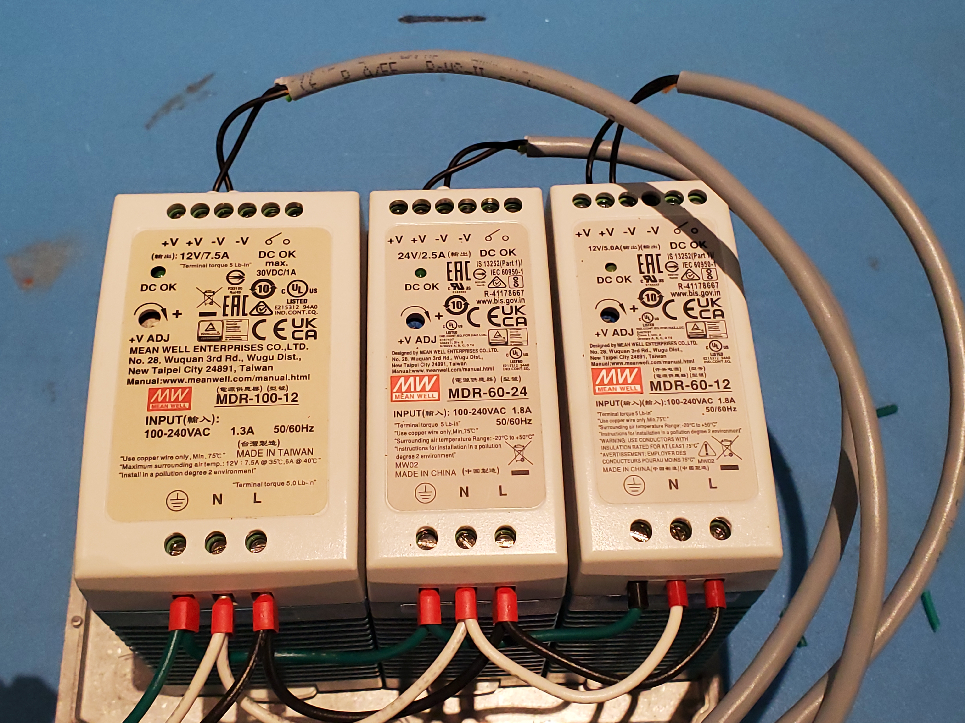
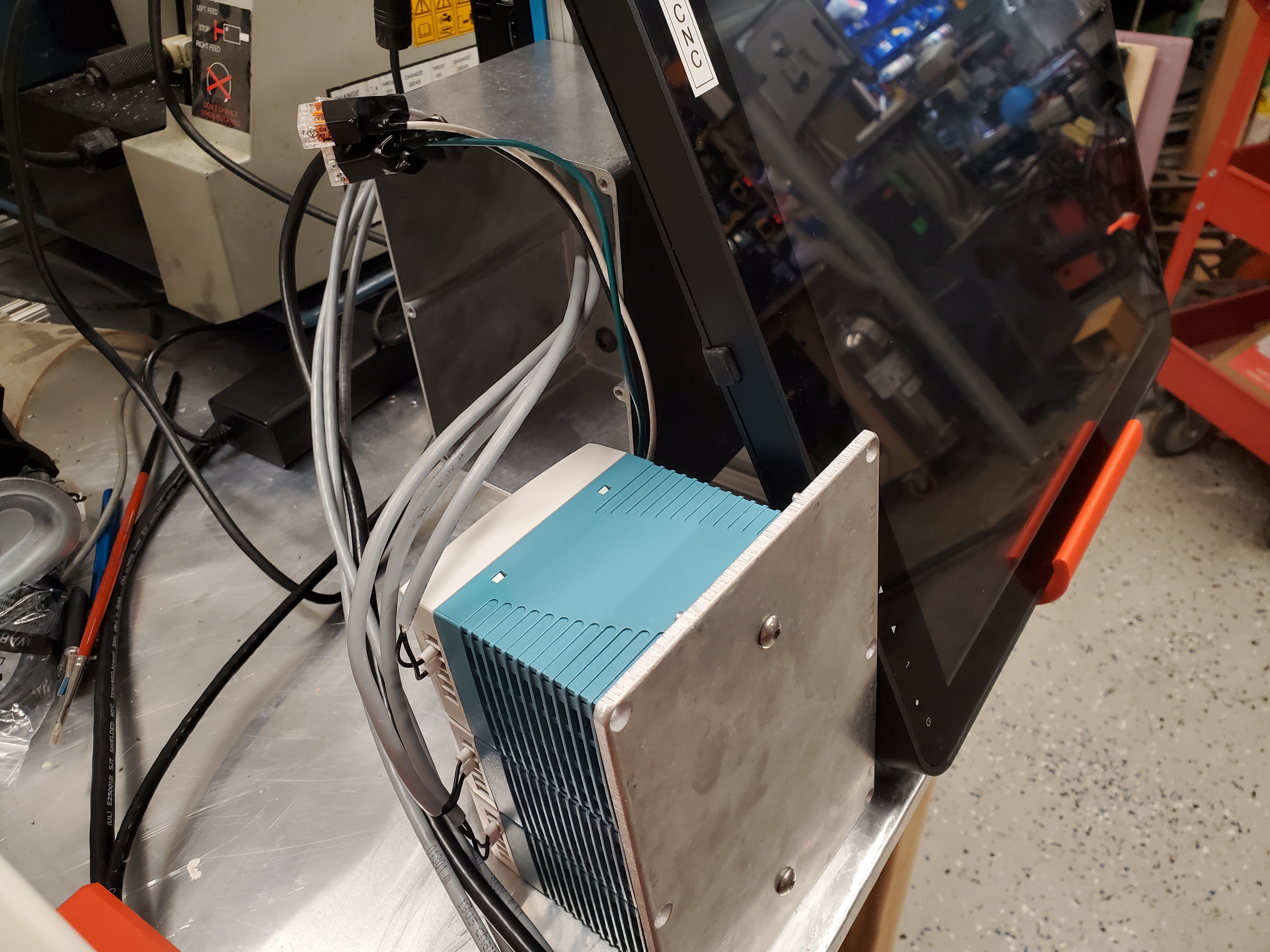
The enclosure has four cable glands, one for 120VAC input, and then a 12V 7.5A supply feeding the NUC, the 12V 5A supply feeding the monitor and the 24V supply providing power for the enclose light. This all is tucked away underneath the monitor and hides the mess of wiring. For the NUC I increased the output voltage to 14V to put it closer to the intended 19V operating voltage. Enclosure LightThe enclosure itself is great, however some basic lighting would go along way. There is a thin space between the top and front openings where a long slim led could fit. I opted to cad up a simple printed bracket that magnet-mounts to the case, specifically to be removable and not result in adding holes to the case. This particular light uses the M8 style connectors, specifically a 3 pin version. Space was allocated to fit either a right angle or straight style M8 connector. 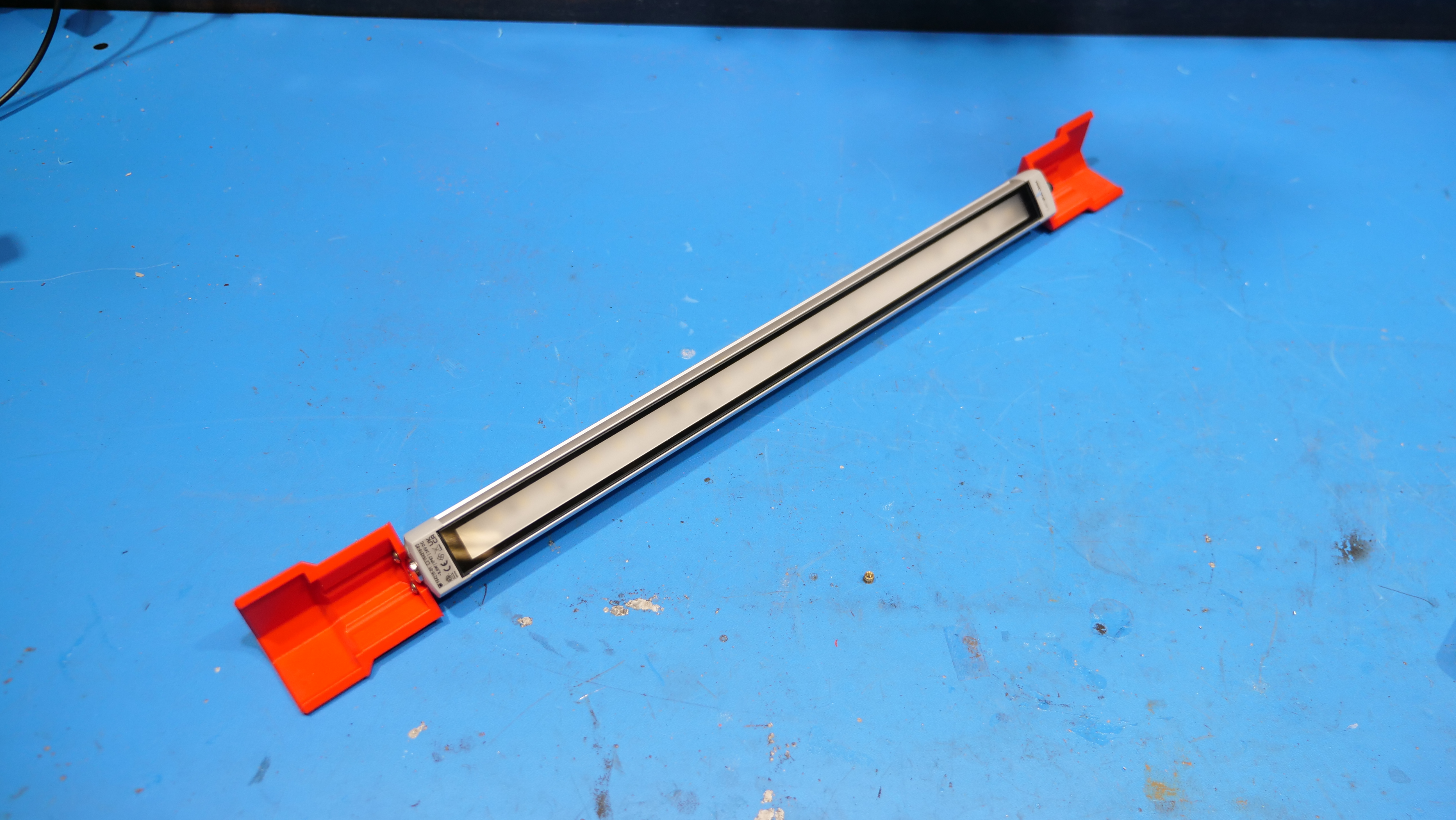
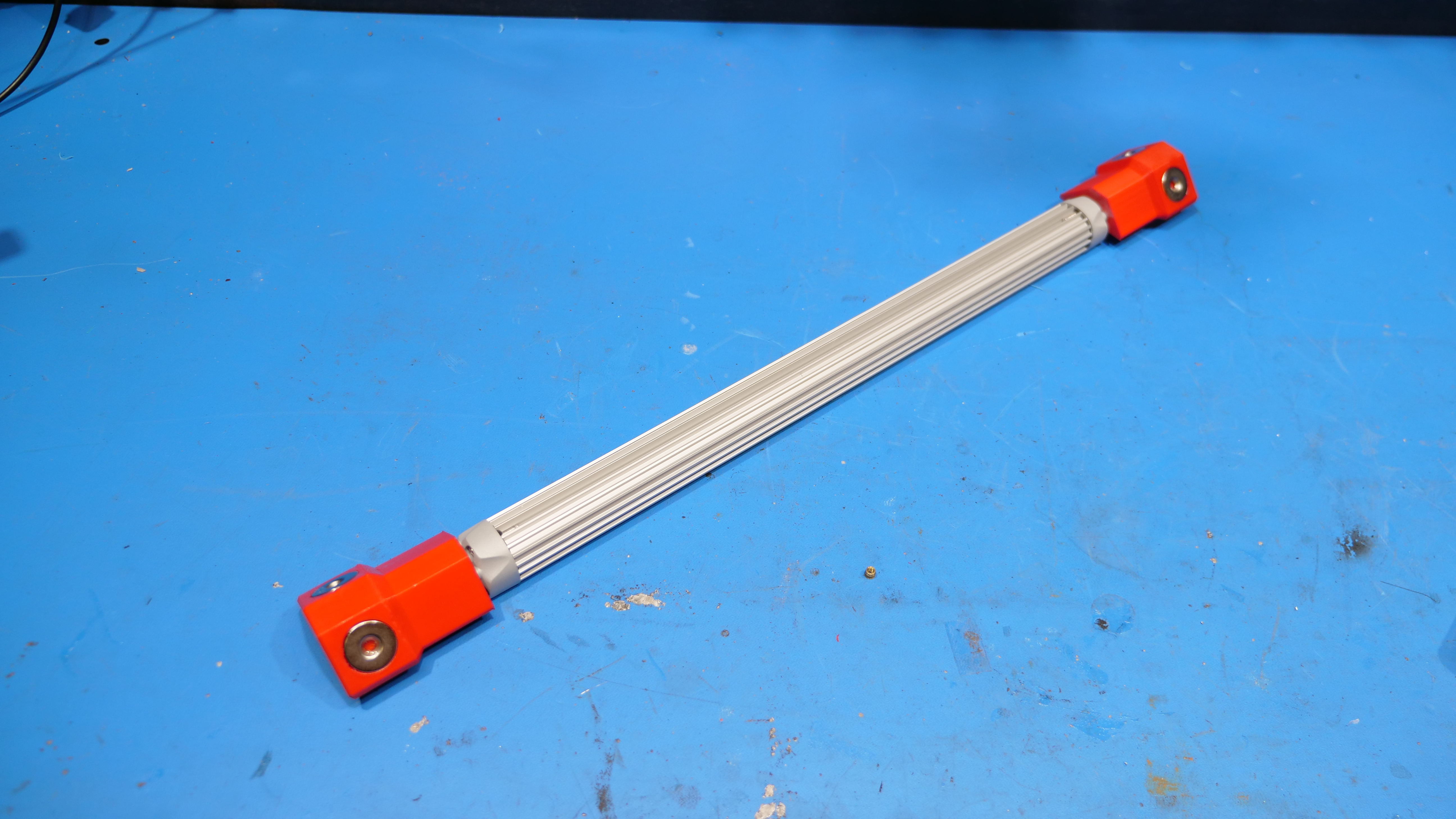
Assembly is fairly quick, 3/4" OD 1/8" height magnets are glued in place to each of the 3D printed adapters, the subsequent printed parts are attached to the light with two M3 screws. For cable routing I opted to use these magnetically mounted cable holders [Link] and fed the final 24V supply out via a cable gland mounted in the top left corner of the enclosure. 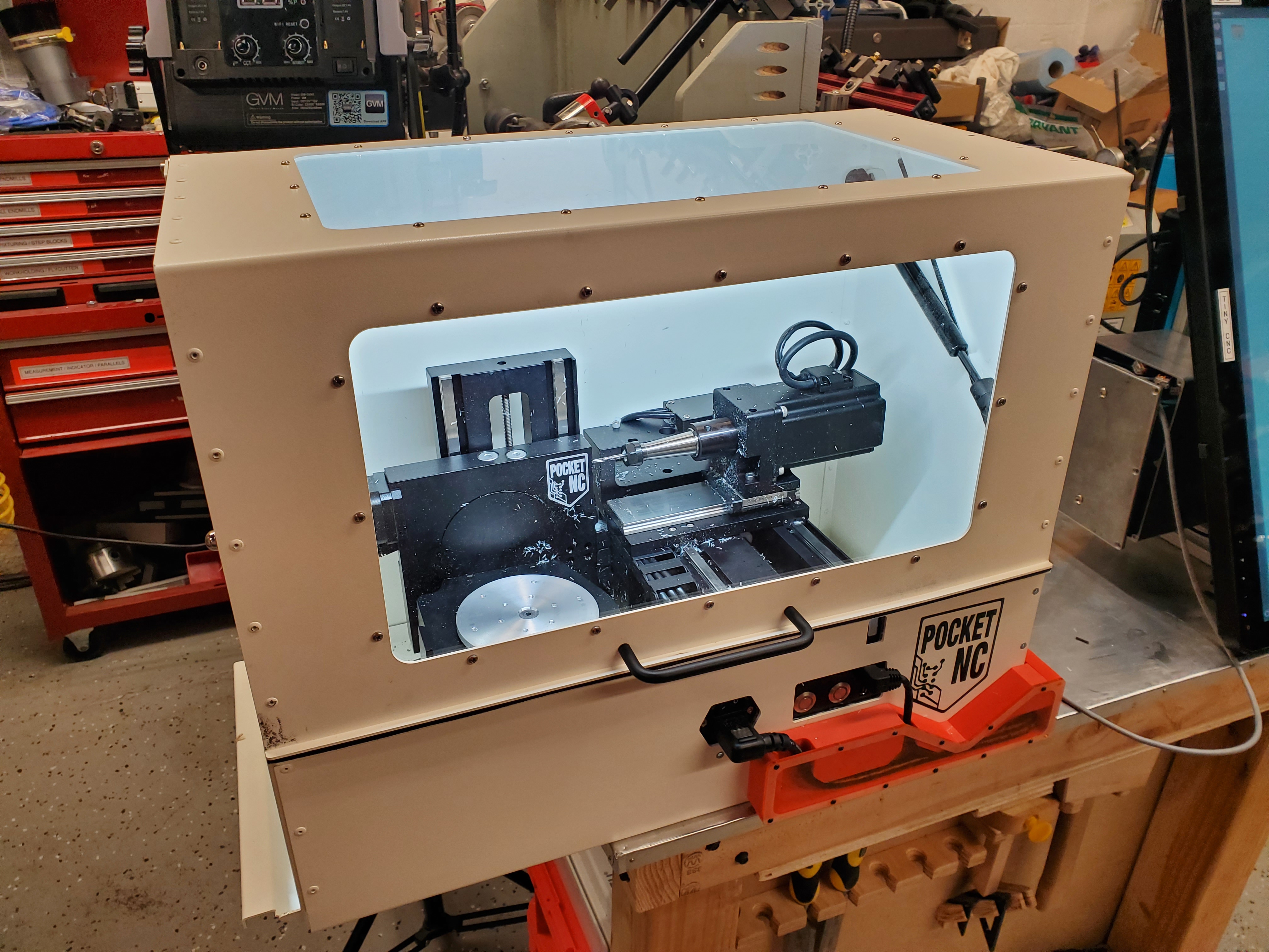
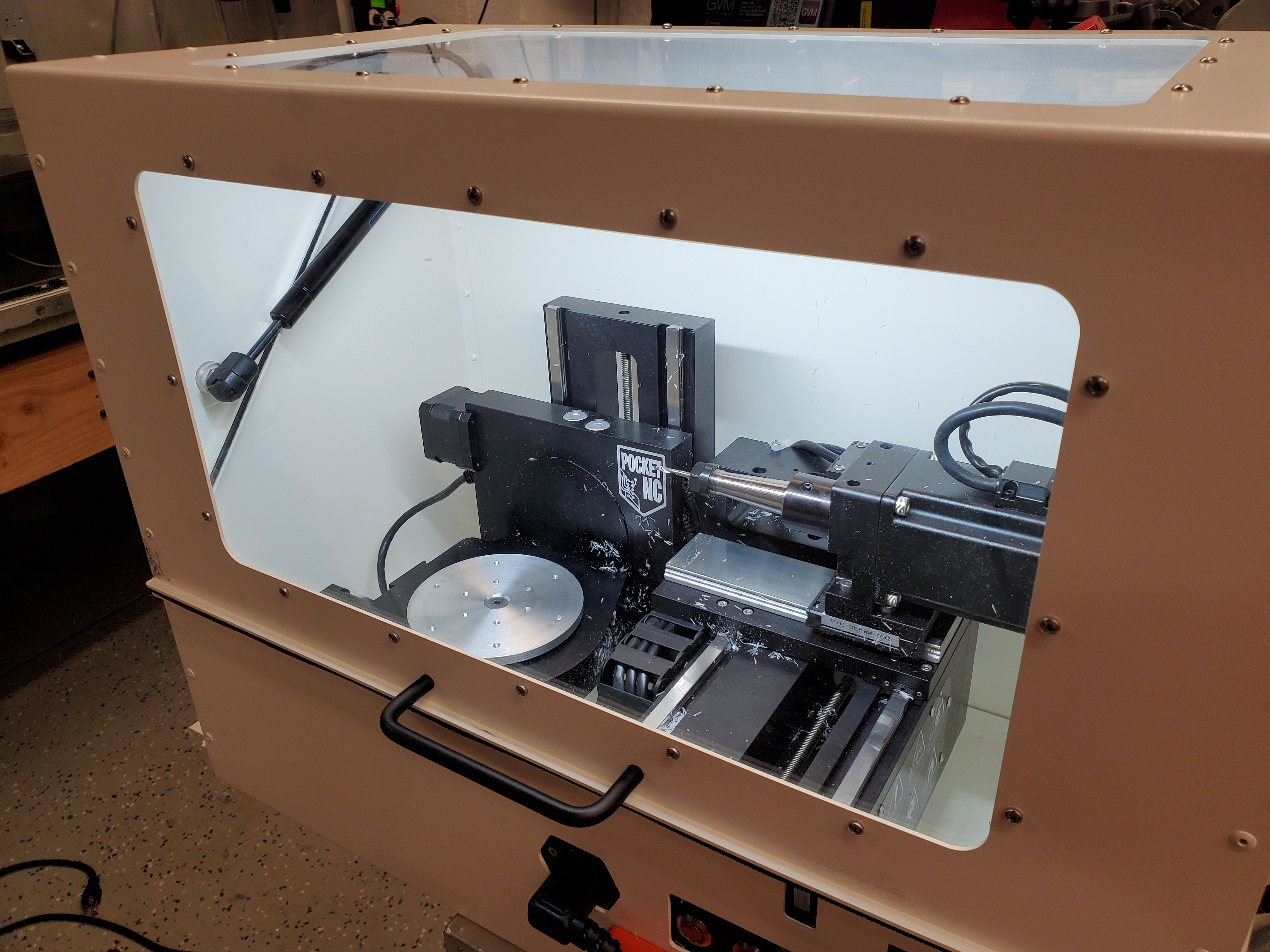
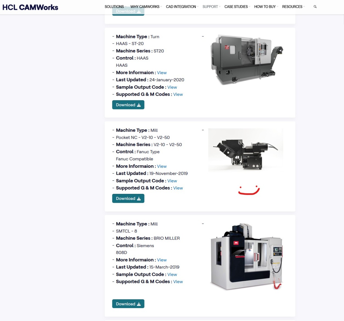
The lighting really turned out great, from the front and top the fixture is so recessed that there's no glare, while the tooling is very visible. In total, at 24V we have ~9W of light power, which seems reasonable. I've debated repeating this on the opposing side however the recessed area is significantly smaller and would be hard to hide as effectively. Thoughts on CAMI have a lot of experience with SolidWorks, while Fusion 360 is looking promising as an alternative, I went through the process of evaluating how well HSM works would do with the pocketnc. Comically the CAMWORKS package for the pocketnc is hiding between an enormous HAAS lathe and a large Brio Miller Mill. There's two orders of magnitude difference in size between these machines. You do need to provide an email for accessing the HCL CAMWorks config file but there is no fee for that file. 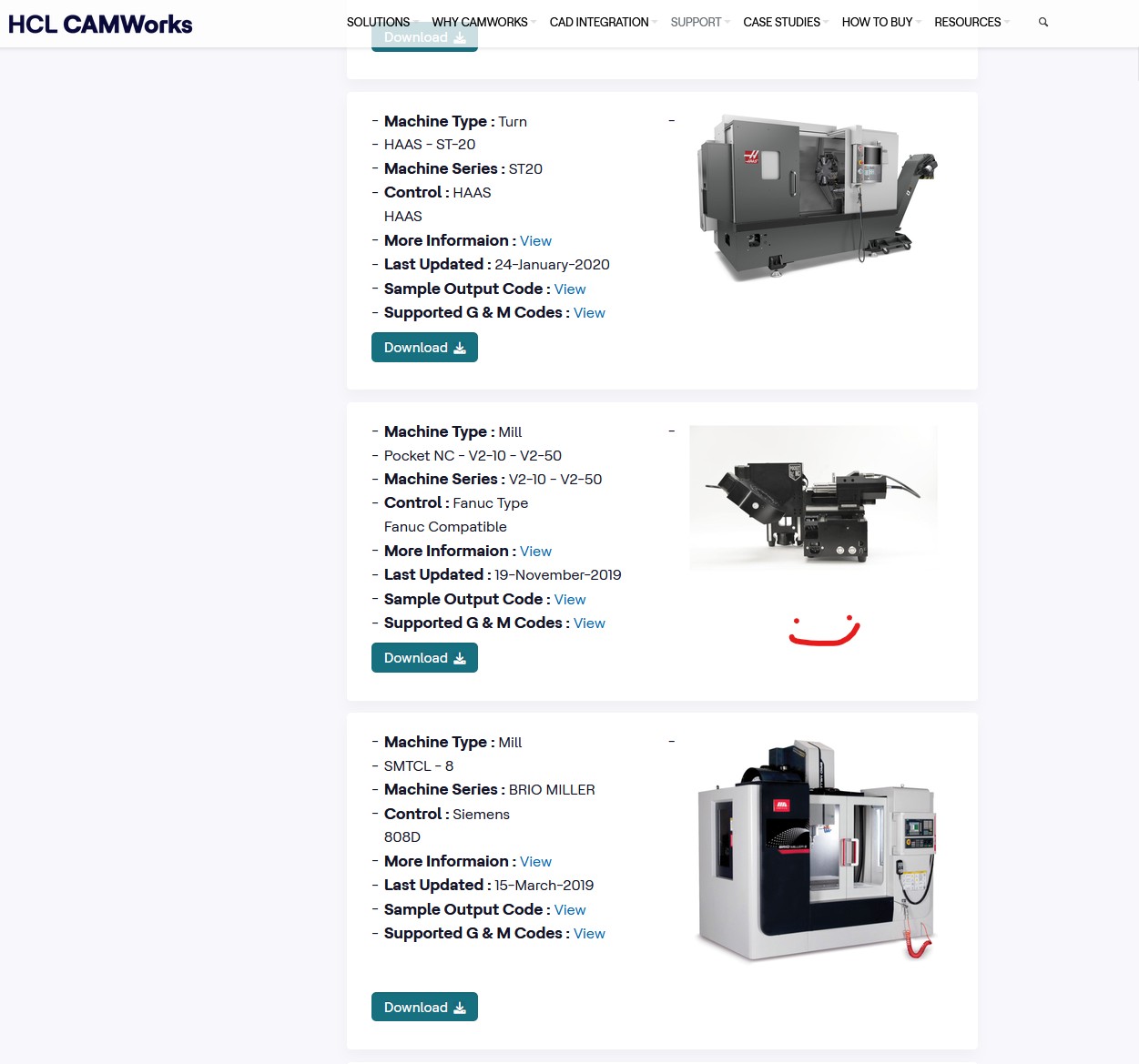
CAD FilesHere's all the associated files for this project, copies are also on Printables and Makerworld Concluding Remarks
If you have questions or comments, ask below or send over an email. May the 5 axis CAM flow freely
Have you noticed that there are no advertisements or ridiculous pop ups?
Want More?
|
Post your comments! |
|
Comment Box loading
|