
Dane Kouttron
This project / write up is in progress, check back for more soon!
Project Started: 01/2023

Reverse Engineering Audi 48V Hybrid MotorThe Audi Hybrid's have a really spicy alternator shaped motor that provides launch assist and regen breaking all in a small low voltage package. The following documents trying to wake this up for non-audi uses, like goofy electric vehicles. |
Some Project BackgroundWhen I started the e-torque reverse engineering it seemed to be the most widely-available option in terms of 'low voltage' hybrid motors. These motors are great for 'large but not enormous' robots, go-karts and the like. Audi ended up also embracing the mild-hybrid approach, but with a lot less publicity. Lets take a look at the 48V Audi options and try and wake them up. For the sake of simplicity, and instead of writing motor-generator, I'm opting to call these things an altermotor, or alternator-motor. An eBay contender appearsThe first one of these I was able to find on eBay was a 2021 Audi Q8 3.0L Alternator Generator, part number 4M0903028N. Lets see what we can find just from the photos alone. There were three of these, used 'not working' and needed to be 're sealed', so hopefully this is just a mechanical issue not an electronics issue. ~170$ later I purchased a used motor, feel free to donate to the 'Dane science' down below. 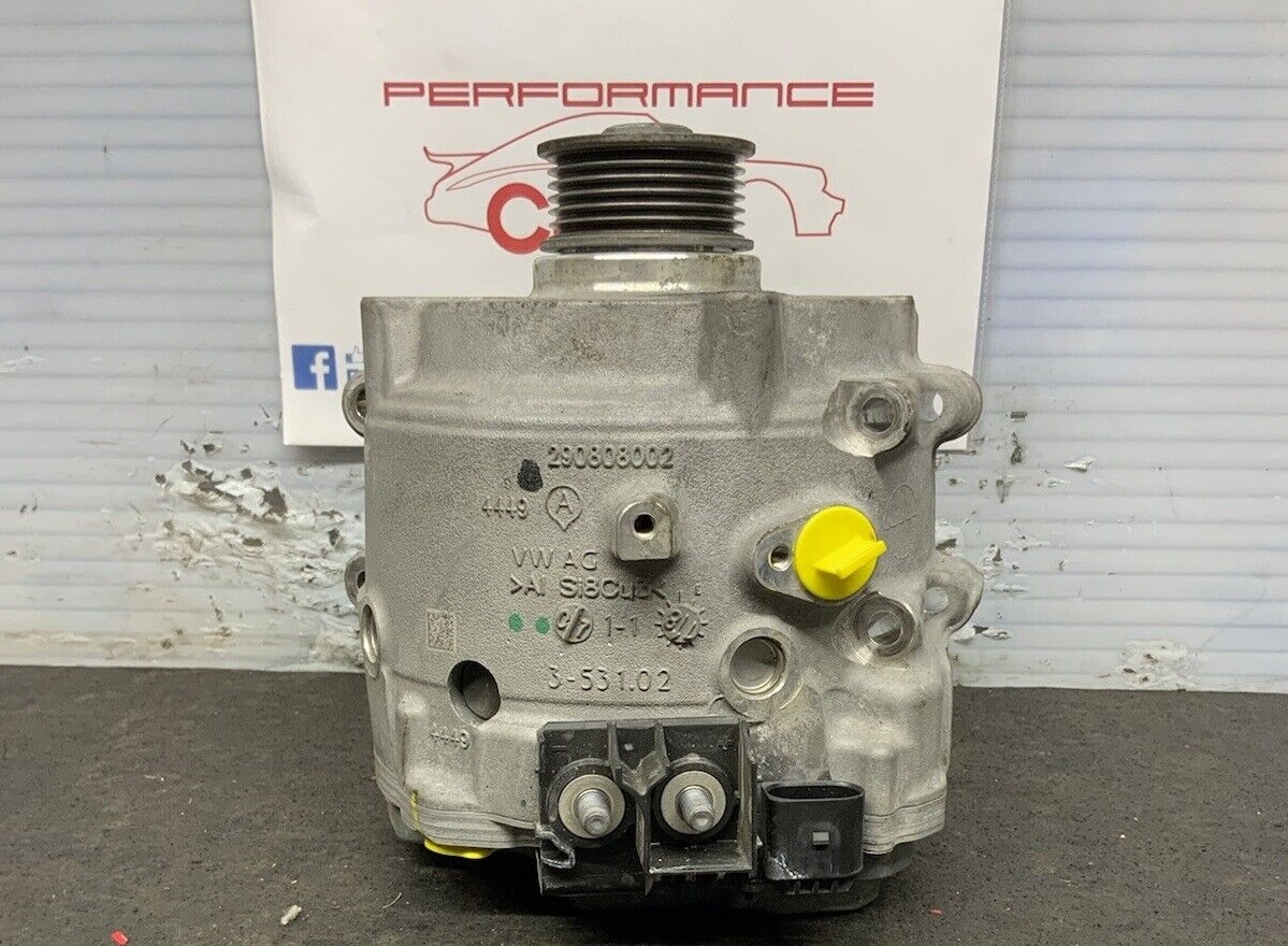
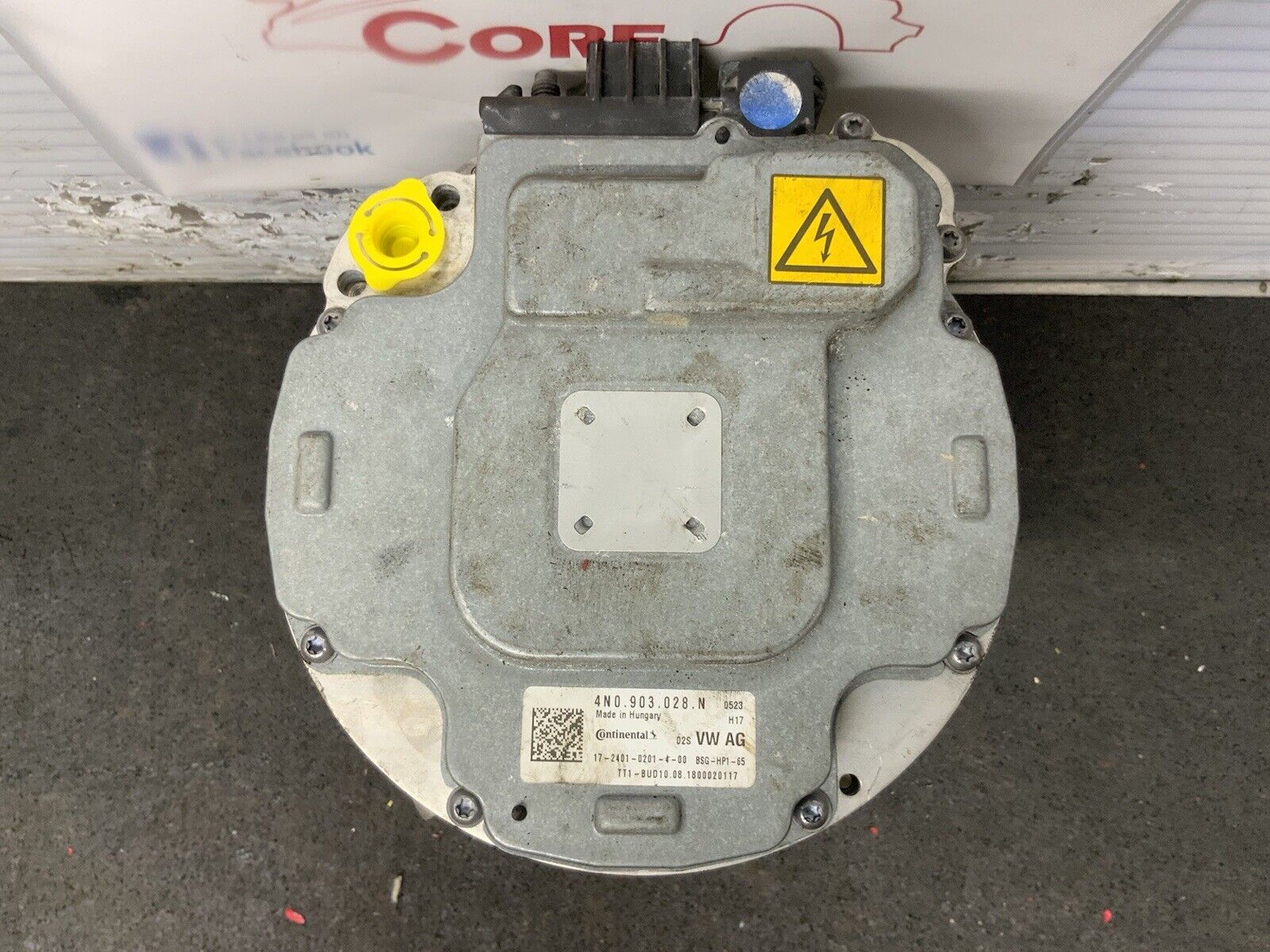
These photos tell us a lot. We have our familiar rear cover from Continental and a different power input location. Its possible that this vehicle floats the hybrid bus off the frame and cant use chassis ground. Otherwise this is looking really familiar, given that this has two power terminals, coolant plugs and a communications connector, we are likely looking at another 3phase integrated motor inverter assembly! We also get a sneak peak at the communications connector from the eBay vendor. Different assembly vs the 'e-torque' branded ones, and fewer pins. 5 Pins is 'interesting' we could literally have +12, return CAN-H CAN-L and some kind of wake-up pin? 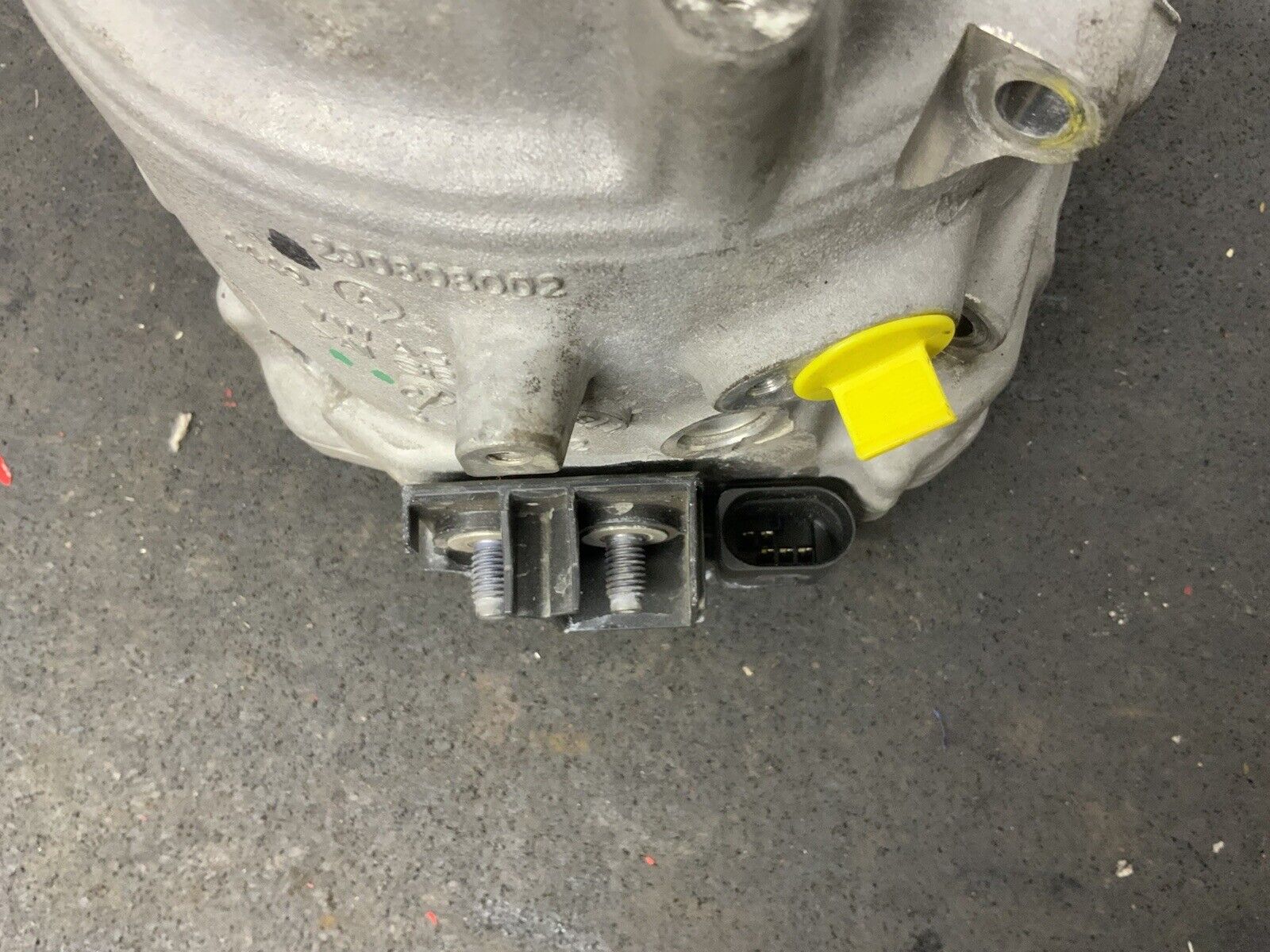
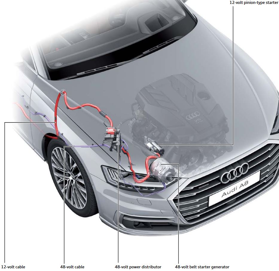
Lets do some digging and find a wiring diagramThere is a basic vehicle overview here, which just shows the belt alternator starter-generator tied to a mechanically small 48V hybrid pack and what appears to be a 12v pack way in the back of the vehicle. This is a little odd but the 'engine start' is accomplished mostly with the belt starter so the 12V loads are mostly auxiliary. 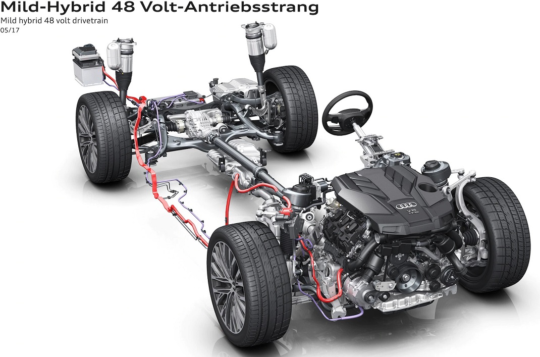
I was able to find some dubious copies of parts of the Audi Q8 'workshop manual'. For the sake of ignorance I'm listing them here, these should be available under Massachusetts automotive right to repair. I contacted Audi to ask permission to post diagrams for research and they ignored answering the question. 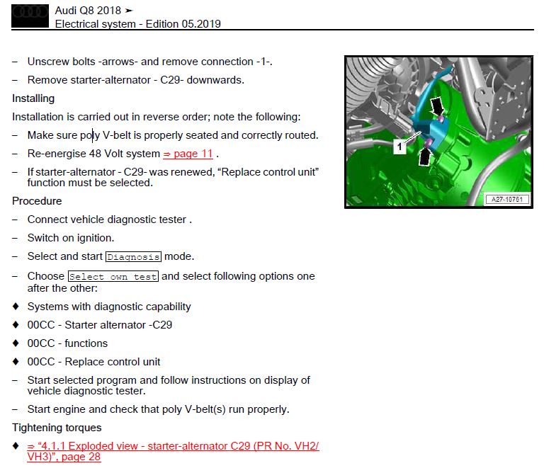
Continuing to run through the Q8 electrical workshop manual for more details, we find out that there are some diagnostic tests that the alternator can do, which is really interesting. 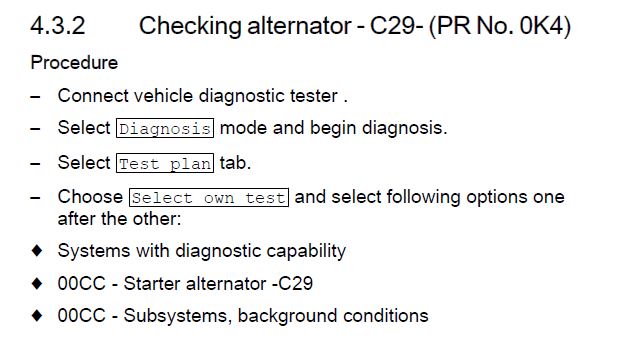
Lets do some digging to see if anyone has documented these procedures online. This is a relatively new car and the Audi crowd isn't really known for DIY repairs, but we may get lucky. Technical Service Bulletins also can provide a bit of a sneak peak if these have issues overtime. The audi forums were really interesting, with everything ranging from late December 2022 to early 2023 sourcing issues and then a claim that there's a firmware issue in the alternator that causes them to explode, and an associated firmware update to fix this? Wait is there a firmware package for this motor hiding online somewhere? Forum posts are here [link] and here [link] 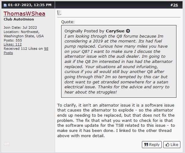
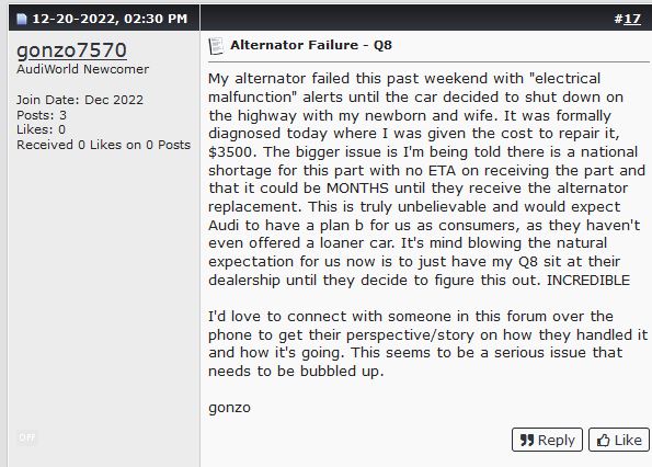
Its always hard to tell from online forums if things are an actual common issue or like just a highly concentrated compilation of folks who are having problems, its not like folks join forums to post how much they don't have an issue. lets see if there's a technical service bulletin (TSB) online about this motor. Wow this is happening *right now* the issue seems to be present in ~January 2023. Forum post is interesting [link], we get a new TSB that super seeds the old one. I wonder if the motor I eBay'd was one of the 'oopsie' ones, given that the shop had three of these its possible they are all doomed. 
Here's the TSB [link] and local copy [link]. Lets see what we can find. I wonder if I can argue 'right to repair give me your firmware'. The first bit we learn is all of the Audi car models that have this same part, it turns out there are a lot! The same part looks to be compatible with a lot of vehicles so eBay searches can now span a lot more vehicle models. Lets update the chart above to display this. 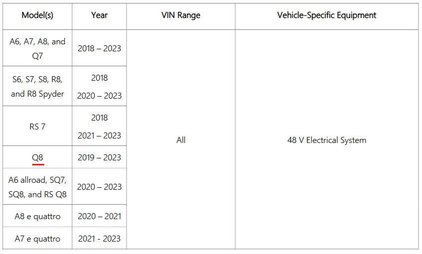
Ok so the TSB is a little odd, the starter motor-generator needs to be upgraded, if it doesn't it drains down the 12v rail. I know from the 48V e-torque motors, the 'logic' power for the motor is fed from a 12v battery line, and routinely pulls ~1A when it is awake. While ~1 ampere does not sound large, a 12W steady-state draw will chew through a normal pbacid battery fairly quickly. It looks like the 12v battery is topped off from the 48v bus via a buck converter, so its possible that when the alternator fails, the hybrid 48v battery is no longer charged, but the 12v battery still has a parasitic drain which eventually results in the 12V bus dropping out and the car faulting. This is *my best guess* the TSB does not have an actual root cause shown. This TSB does point to another TSB [TSB 2011732] regarding software updates, we will check that next. There's nothing else really in this TSB, just update firmware 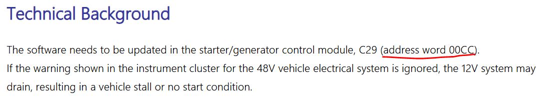
I genuinely wonder how terrible it will be to try and get access to Audi firmware or firmware loading tools. Would these technically *have* to be available under right to repair?
Lets see if the A8 / any of the listed models have a config file. These are installed in C:\Ross-Tech\VCDS\Labels by default. The LBL files are plaintext while the CLB files are some compressed / binary file format. The naming scheme is, not at all straightforward, so I just opted to dig thru the LBL files 
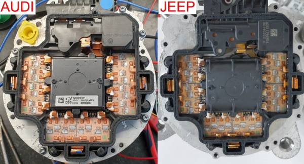
An image of the internal PCB appears from Ukraine [link], which is great because it confirms my thoughts that these are similar. While the initial image is not high resolution it is enough for us to identify some significant PCB changes. Take a look for yourself. We find that only 5 pins come down to the PCB from the mating connector, which matches what is populated in the connector itself. We also find the main micro controller is ~TQFP ish instead of BGA. Its also an ST part, which means re-programming this is *feasible*. A lot of the power stage on top is also not present. I had surmised this was the LV supply for the micro, given that the ST is likely a less advanced micro it probably consumes 1/10th the power. Everything 'below the equator' is nearly identical. This is bizarre.
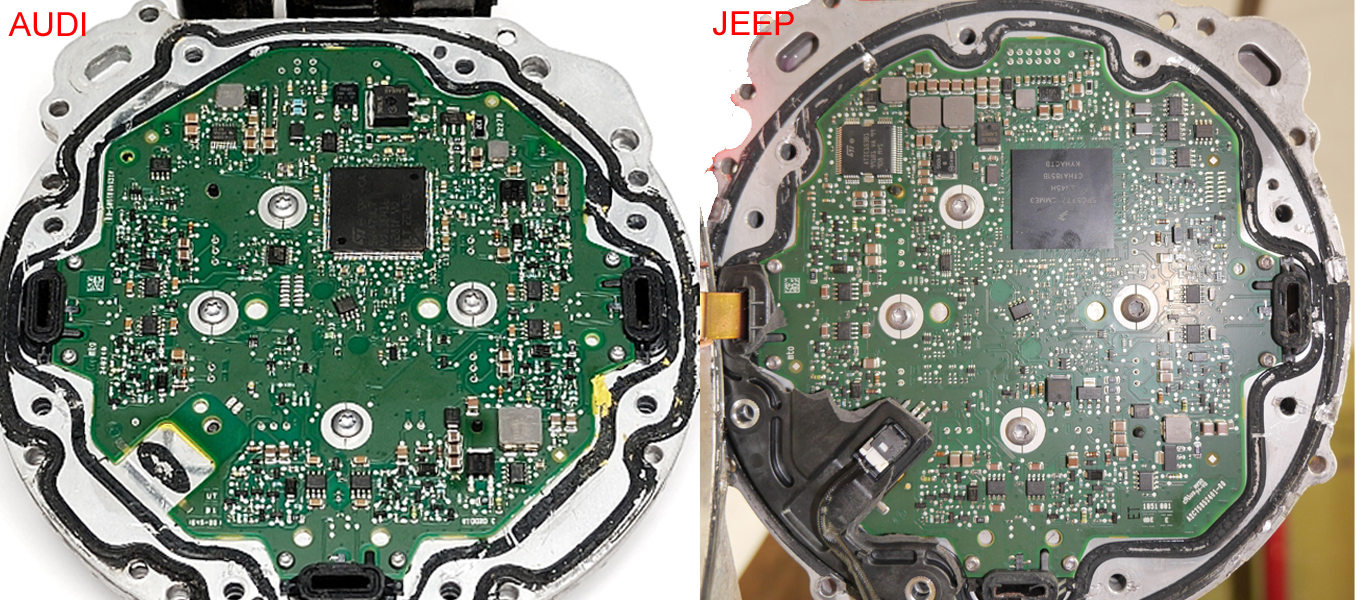
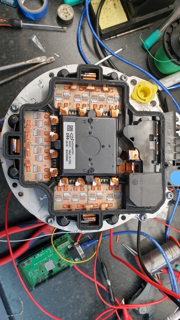
While we're comparing the motor, here's a comparison between an image from Damien Macguire 's audi motor vs my jeep e-torque motor, again not really a huge difference but we do see a possibly different bus-capacitor? The Jeep variant has a 63V 470uF capacitor, while the Audi has a 330uF cap. Given that they are the same size, maybe the Audi version is a higher ripple current rating? Generally with a fixed volume of capacitor you trade off between capacity and ripple current, as to attain a higher capacitance you need more surface area and all things equal to do that you use a thinner electrode so you can fit in more volume of electrode. 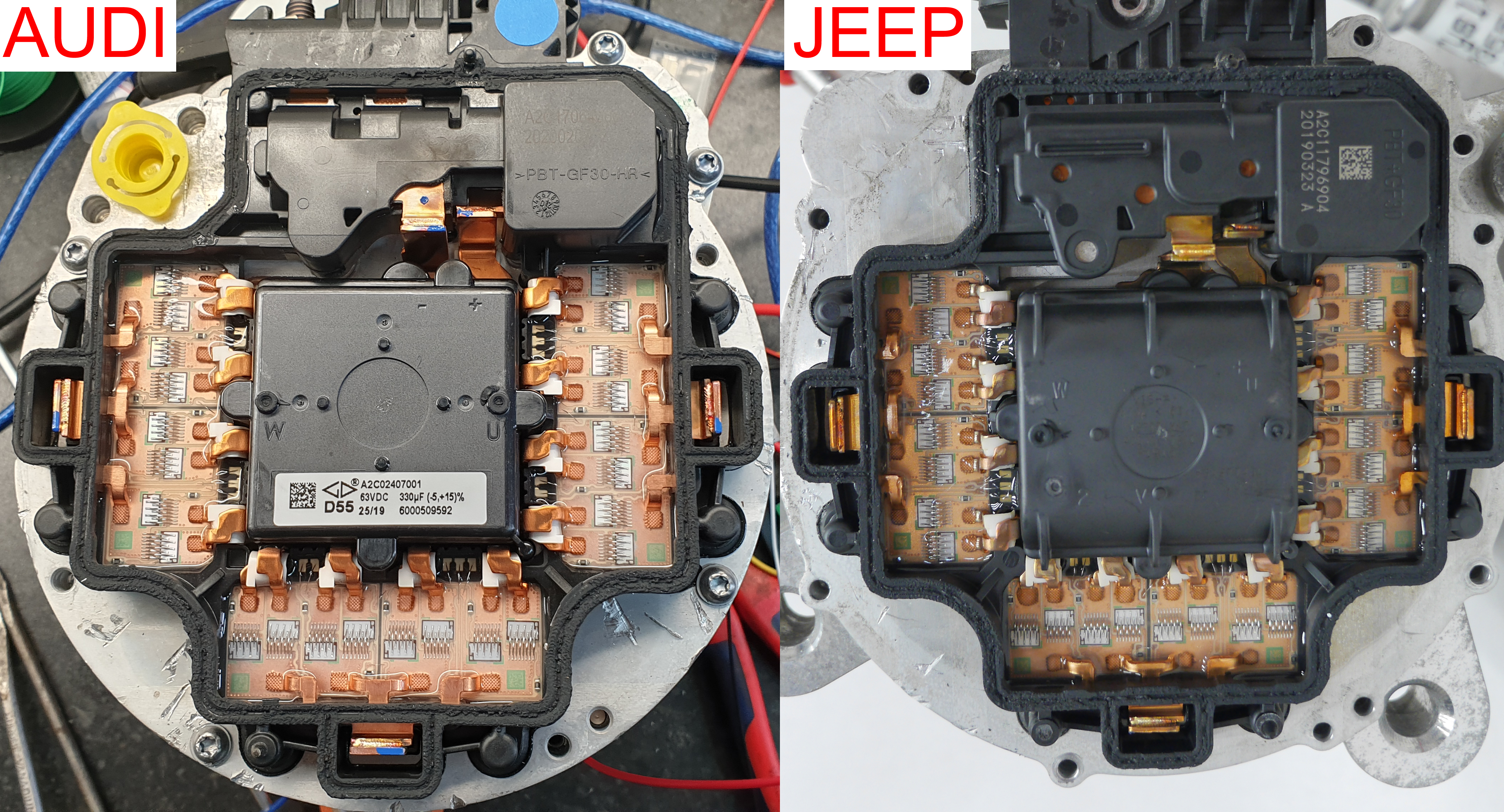
Googling that part number doesn't give us anything useful, but the a2c02407001 does link us to, a TikTok hosted ondouyin.com [link]. Oh boy is this worth it? After some sleuthing later I was able to uncover the video: 
Here's a copy of the video [link]
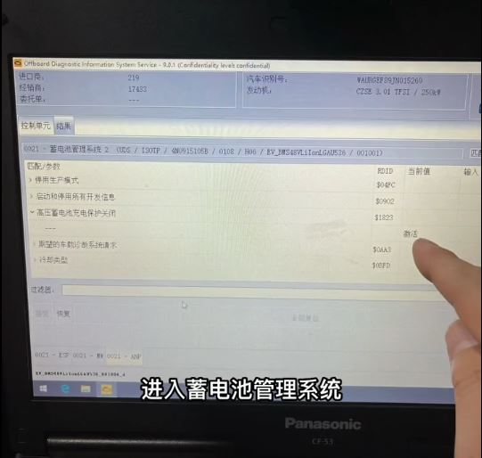
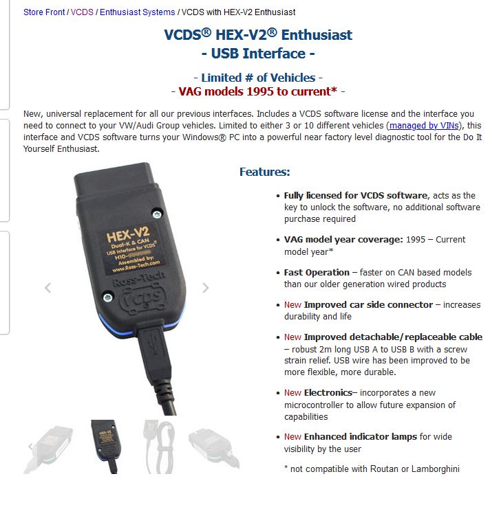
Some googling later, we find that off board diagnostic information service is called ODIS. I did find some kinda installer video [link] which looks remarkably dubious. I'd like to pay for software if its actually useful, but I couldn't find a way to do that directly from Audi. eBay it is. As i'm paying for software, its not piracy, although I doubt a full copy is only 20$ from Audi. 
It looks like peak can adapters *should* work with this tool from this form post [link]. I have a loaner Peak Can USB Adapter IPEH-002021 [Digikey link]. At 260$ its a pricey adapter. There is an opto-isolated version, IPEH-002022, which i'd love to grab if it weren't an extra 50$. A motor appears from eBay:
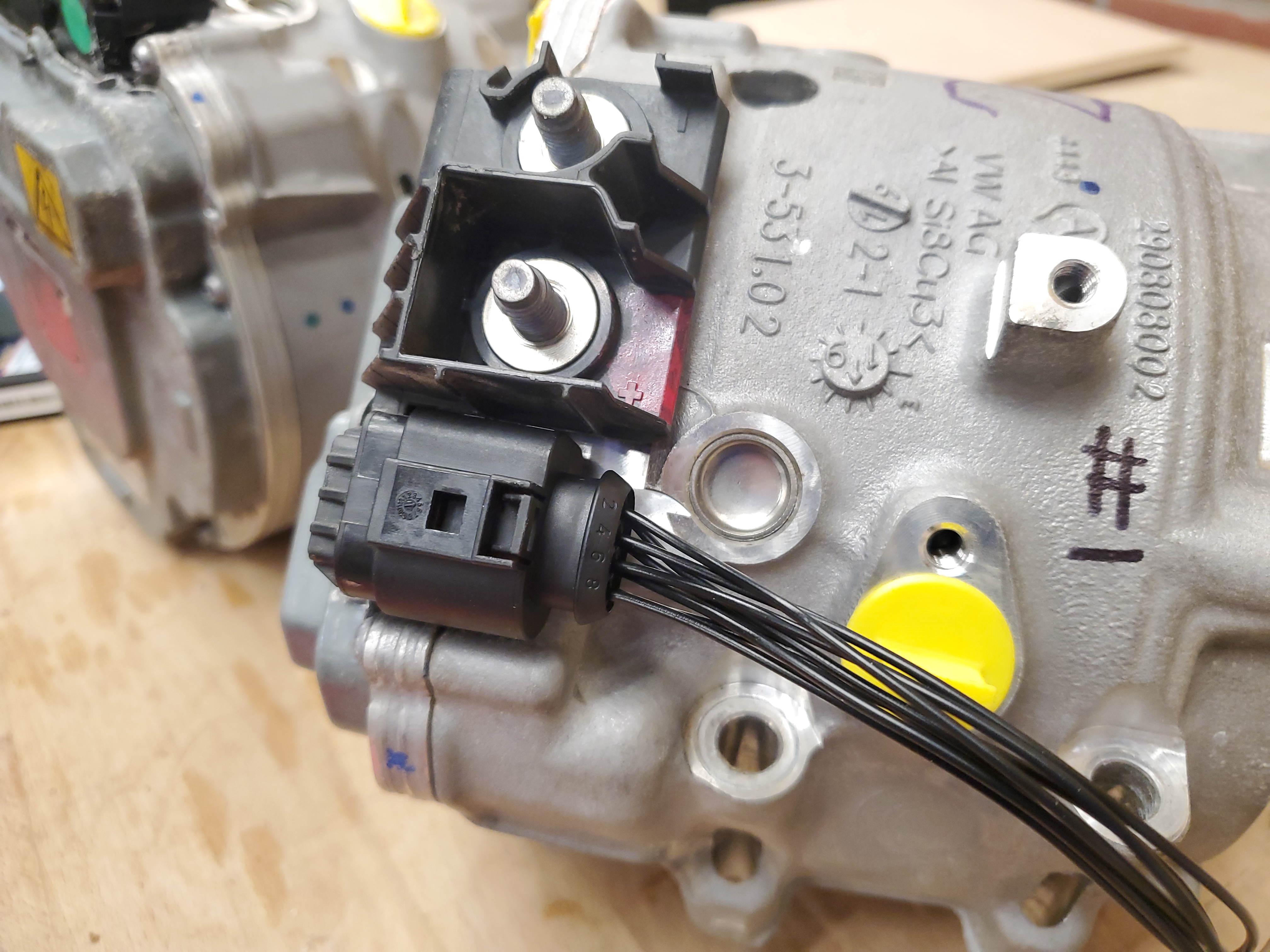
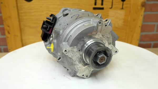
With the motor now in-hand, we can confirm some of the info dug up before, its very very similar to the 48V E-torque. The major noticeable exceptions are the power lugs, the communications connector, the mechanical mount points and the coolant connection points. This seems like a fairly significant difference, but realistically the motor characteristics are defined by the rotor and the stator. 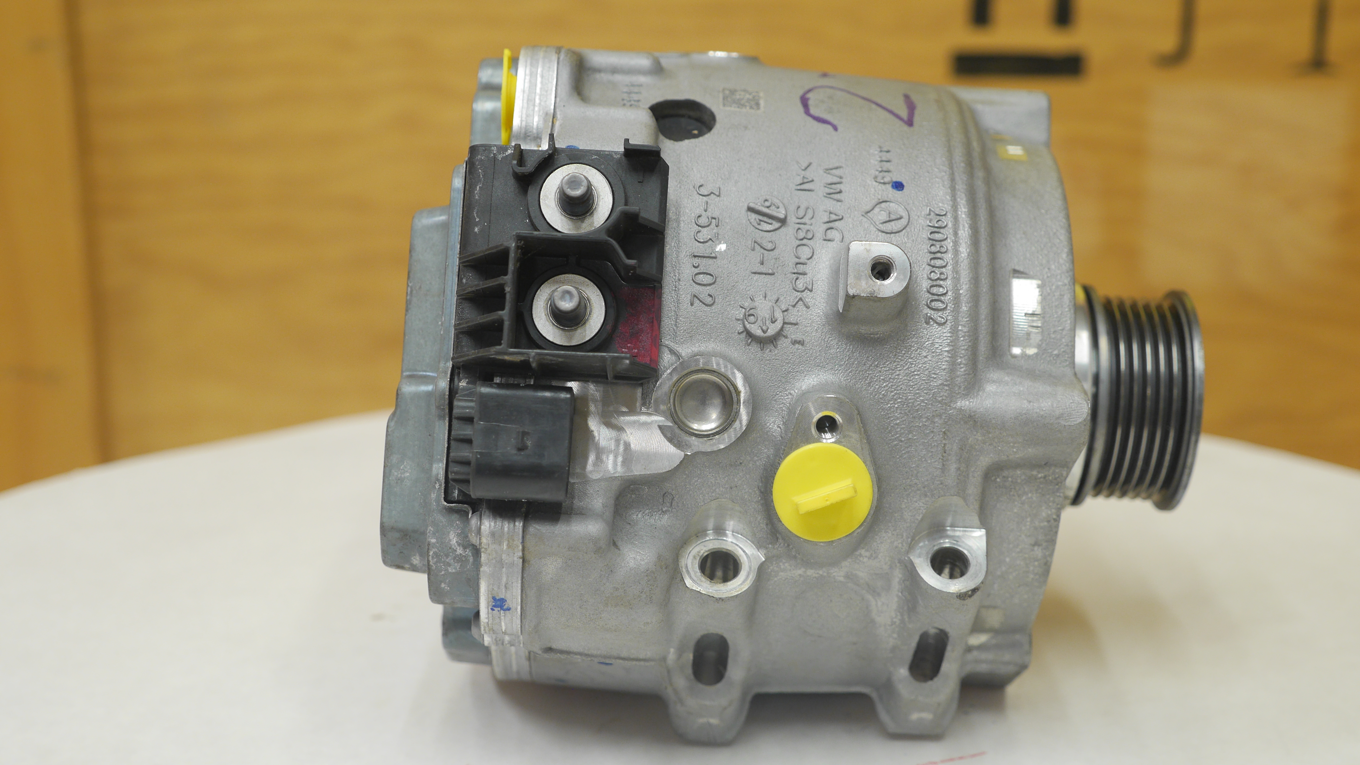
When digging up the motor wiring I unearthed this treasure, what appears to be a partial pin out of the motor communications connector. We learn that Terminal 30 is actually (+12v), terminal 31 is (12v return), pin 3 is (CAN+), pin 4 is (CAN-) and finally pin 6 is PWM. Is PWM important? Its actually really helpful to determine if we successfully 'woke up' the motor. From what I've read the motor commands a PWM to an auxiliary coolant pump to throttle temperature, ideally when the motor is awake we should see it commanding a simple PWM to the coolant pump. A link to the file this came from is available here [link] [local copy]. An NHTSA document also details some interesting bits of the hybrid subsystems here [link] [local copy] 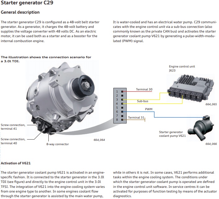
The NHTSA "2019 Audi A8 Electrics and Electronics" self study program is a curious one. Its a short service training manual, but it has some interesting details. I did love the "don't publish me", but its on a national government safety website so this is safe to ignore. 
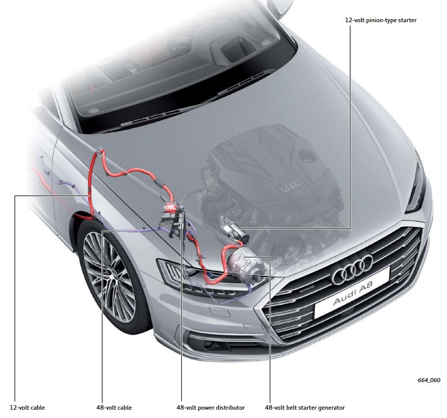
Things we learn from this self study:On the A8, the 48v mild hybrid system powers the 12v systems via a DC-DC, so the nominal order of operations is shown below. The engine has a conventional starter motor (I imagine this is due to low temperature engine start load requirements). Power to recharge the car transfers thru the serpentine belt to the 48V motor, which charges the 10AH 48v hybrid battery pack (likely 13 cell Li-Ion). This 48v system then dc-dc charges a conventional lead acid 12v battery. The 48v motor can charge the 48v battery at up to 12kw. Considering what we know, this seems implausible. We know our hybrid battery is ~500 watt-hours, recharging at 12kw would net a 24C charge rate. That should raise some red flags, as even very exotic battery chemistries can barely withstand this. If you're not familiar with c-rate, check out this article from battery university [link]. Now it might be time to find out what they are using as a hybrid battery. Its likely absurd. Things continue getting weird, the 48v battery is way back in the trunk. For reference, to transmit 12kw at 50V, you need 240A. That's some sizeable cable, like 3/0 size copper cable. Not only is that large, it runs the length of the vehicle. Very odd. This next part gets even more confusing: 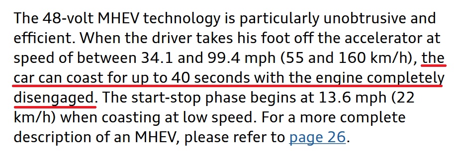
The vehicle can run off the alternator-motor with the engine off for 40 seconds. This somewhat changes the game here, as I was under the impression that the altermotor is tied to the engine via a belt. How can this run decoupled? Is there a one way bearing somewhere, so the motor can provide power with the engine disabled? The more I think about this sentence the less sense t makes. The altermotor would have to spin the engine sans-fuel to get power to the wheels. Am I missing something, lets keep reading maybe this is spelled out more. A normal car at 70mph can 'coast' for 40 seconds when the engine stalls, maybe they are just claiming that as a feature? The car can roll is a feature?
I make the argument that the battery is undersized, this is namely tied to the motor's capacity. Given that it is liquid cooled, using this motor at 12kw would drain a fully charged 500wh battery in a little over 2 minutes. Situations where this could be useful are namely large hills, on a hill climb you benefit from the extra stored energy and can recoup that energy on the return back down the hill. Two minutes of hill climb seems long, but pick a spot in LA / VT and these hill climbs become common. This also assumes all 500wh of battery are accessible, however its common for hybrid application batteries to use dramatically reduced state of charge ranges to increase cycle life. So you likely get a minute or so of boost in hybrid mode. The battery itself is air-cooled, so its further likely this is thermally limited as well. I wonder how much of an MPG difference this nets you after all this extra hardware. 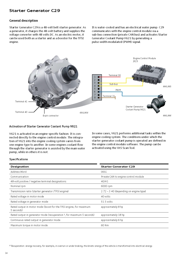
We get some good Intel on our altermotor from page 14: This is a goldmine, we get the motor communications pin out, and that the output to the coolant pump is just a PWM signal. We can use this PWM signal as a hint that the motor's communications are awake. We get some hints at the motor communications, just that its can address is 00CC, which, seems like an odd address and may just be something that's part of the VAS diaognostic systems. We also find out some more information on the battery. It is indeed a 13 cell lithium ion, which is really surprising if it can actually handle the high c-rates from charge / discharge. 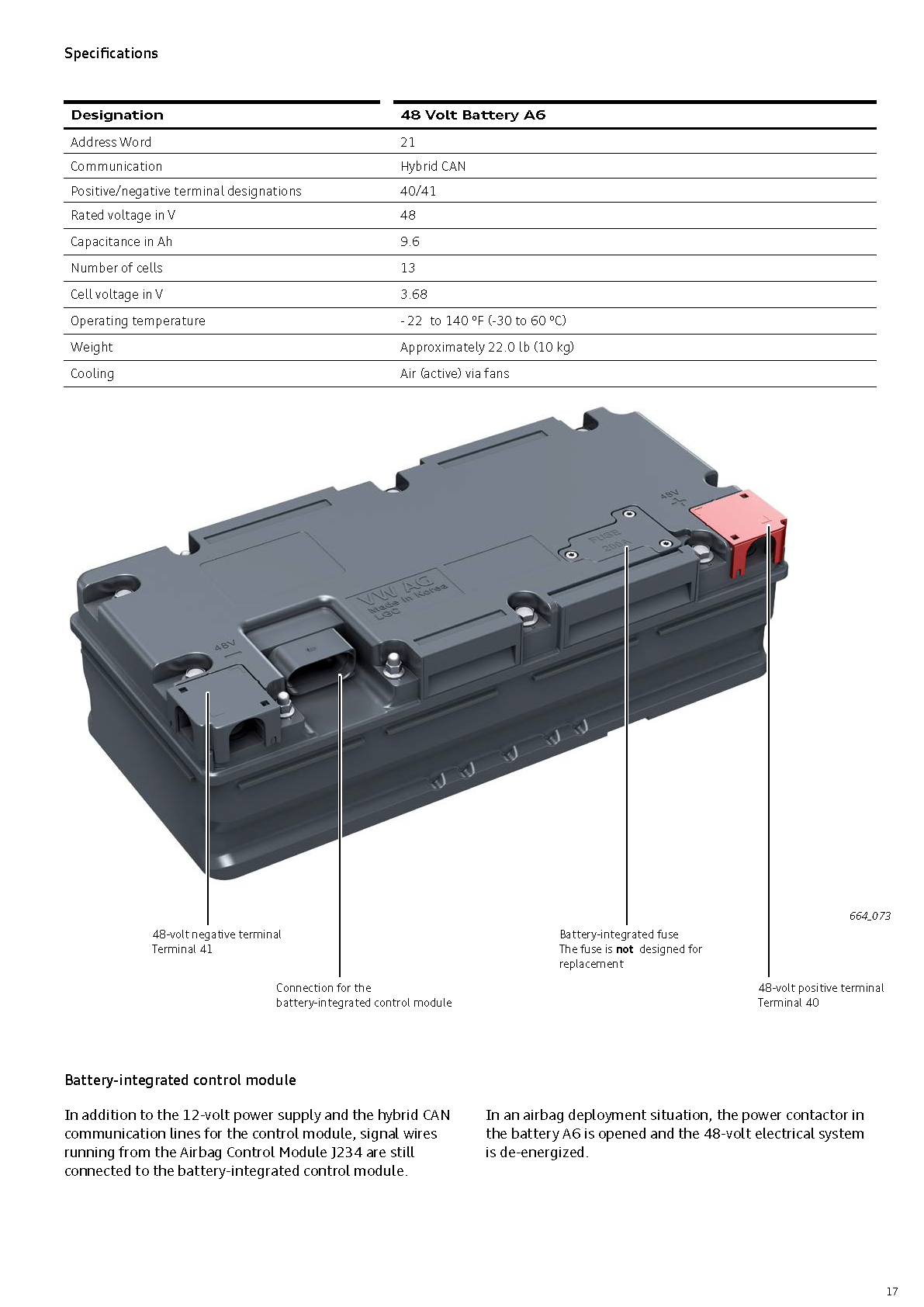
The remaining ~60 pages dont really talk about they hybrid system at all, we get a quick note that the conventional engine pinon type starter is used for "first time" and whenever the engine oil is below 113F / 45C, while the 48V altermotor is used above 45C. We get a somewhat useful snippet as to how this is coordinated on pdf page 65:
The Engine Control Module J623 either receives a start We learn here that the engine control module communicates over private can bus directly to the starter generator. We don't learn what that message contains, or if that message has a variable associated with it for the actual output torque, but we know that at least we should be able to make it spin just with a can message. We do need to look into what the 'coast' feature is, and if it has an associated details possibly related with controlling the motor rpm / torque limits.
For the sake of convenience, lets make a connector pin map and try and figure out what the mating communications connector actually is. Its unlikely documentation is available, but worth a shot first off. 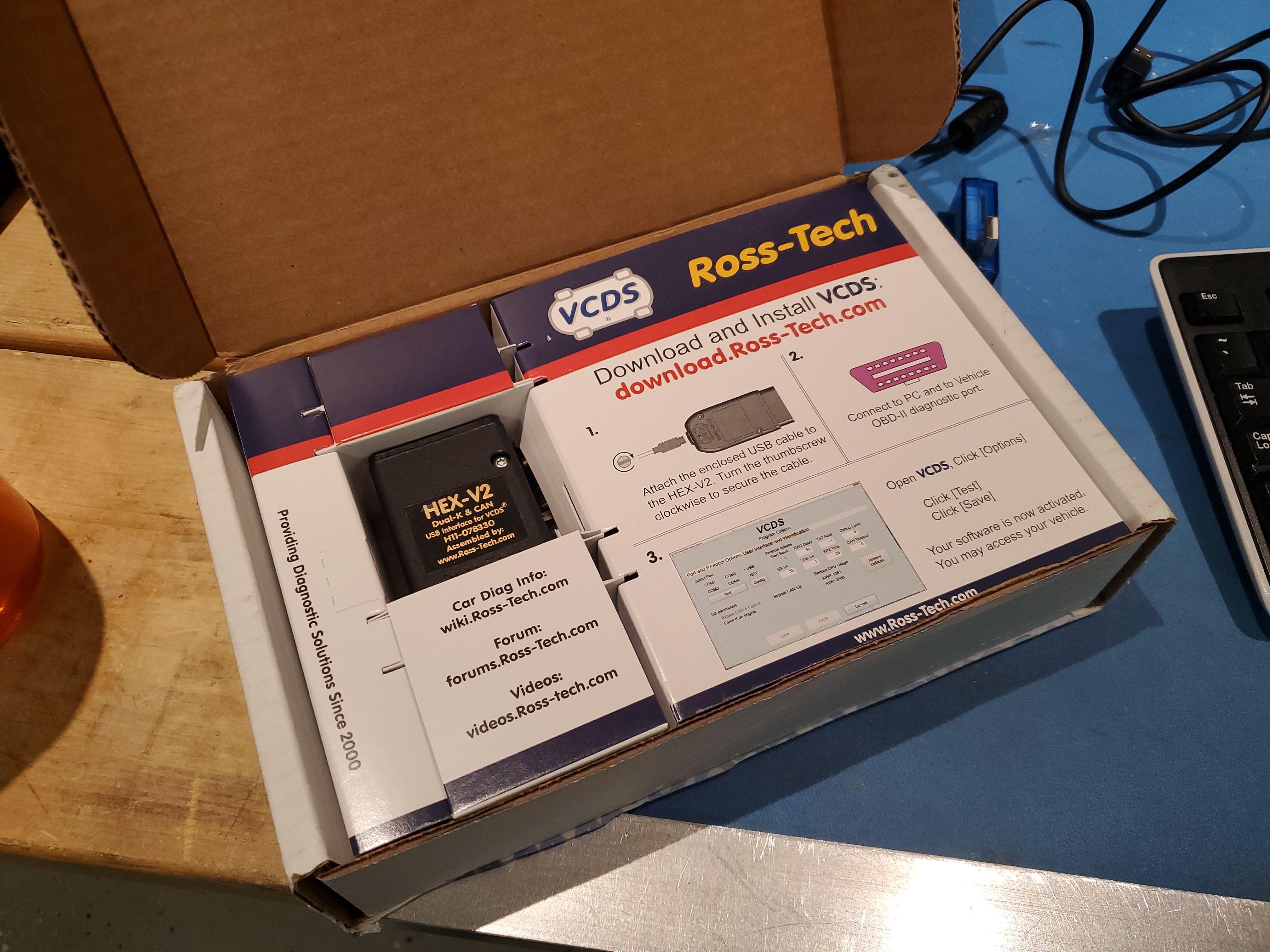
The real impetus for this pricey purchase was this video [link] where the module talks directly to an Audi Dashboard. The auto-shop person nomenclature is bench testing (or out of vehicle testing). Some of the documentation of this setup is buried here [link], the plus side is this tool appears to not want to talk directly to the vehicle controller but can talk to individual parts themselves. This image, below, shows the hex-can adapter connected to a homemade wiring harness tied directly to the dashboard controller with no intermediary body-controller module. 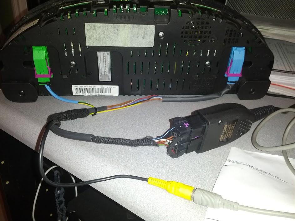
Sounds good, lets throw together a diagram, and in the mean time I will order a OBDII -> Wire adapter from amazon/eBay. I went with this particular one as they colored and labeled the wires, and it looks like all pins are populated. Some of the off the shelf adapters only populate 5 or so pins which could probably end up fairly frustrating. I was hoping to get this from a local auto place, but Autozone [link] / advanced auto / O'Rileys don't stock them and also charge ~70-90$ so 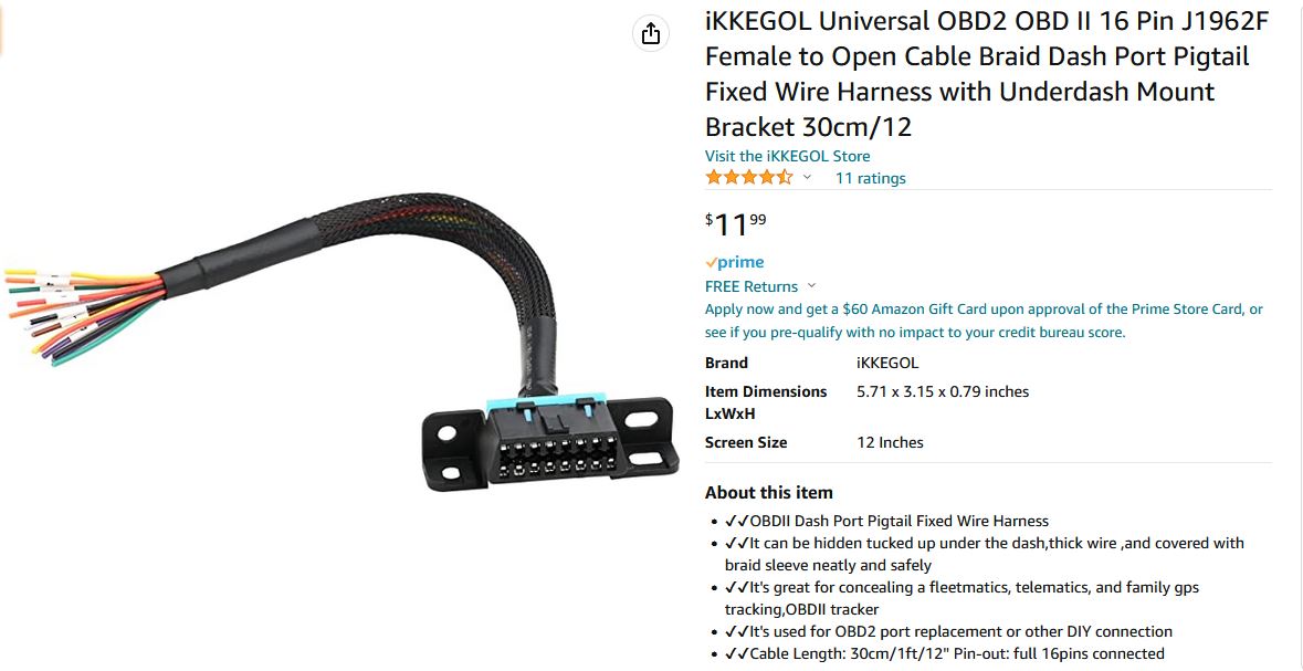
Mating Connector PinoutI was able to find a connector that mates to the comms connector on the Audi altermotor. This unfortunatley was a trial-and-error process, but it turns out the rear parking sensor on VW / Audi cars uses the same size connnector. This was labeled "Rear Parking Sensor Wire Harness Plug 1J0973714", and was available on amazon [link]. This particular cable harness is all black wires and unlabeled, so adding labels helped preventing wiring mixups. 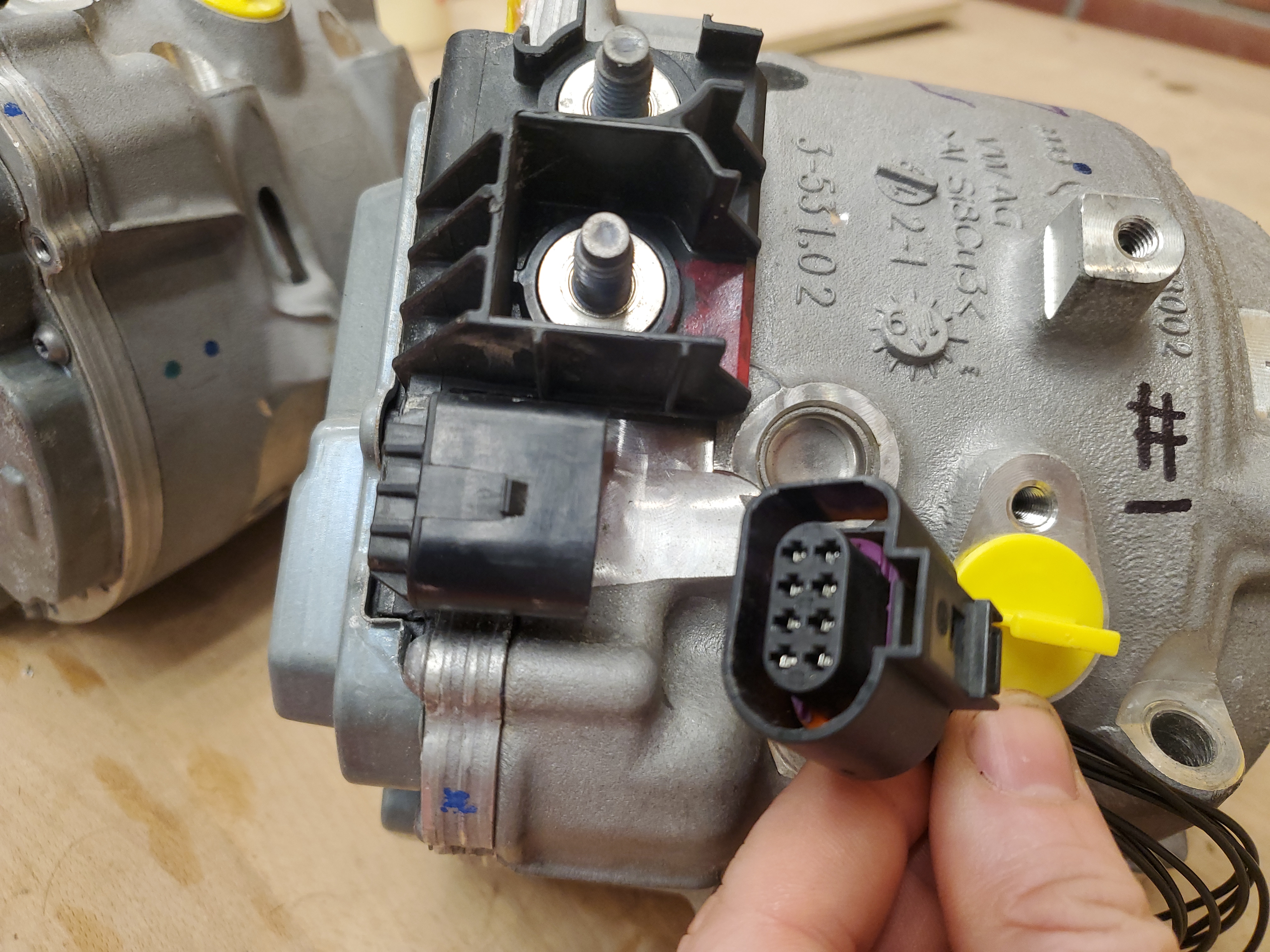
Between the Ross-Tech forums [link] and Audi forums, I came up with this diagram: Dane-ger Dane-ger, a blown inverter:
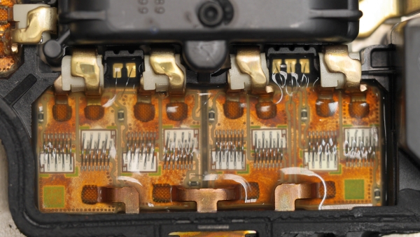
Two of the Audi motors I received from eBay had the same failure as the person who posted the short-form video above. Here's a macro photo after i removed the failed bond wires. This does not bode well, given I now have two dead motors.Doesn't that footprint look remarkably like a TO252, just a bit backwards? Lets grab a closer photo and investigate some options for replacement. 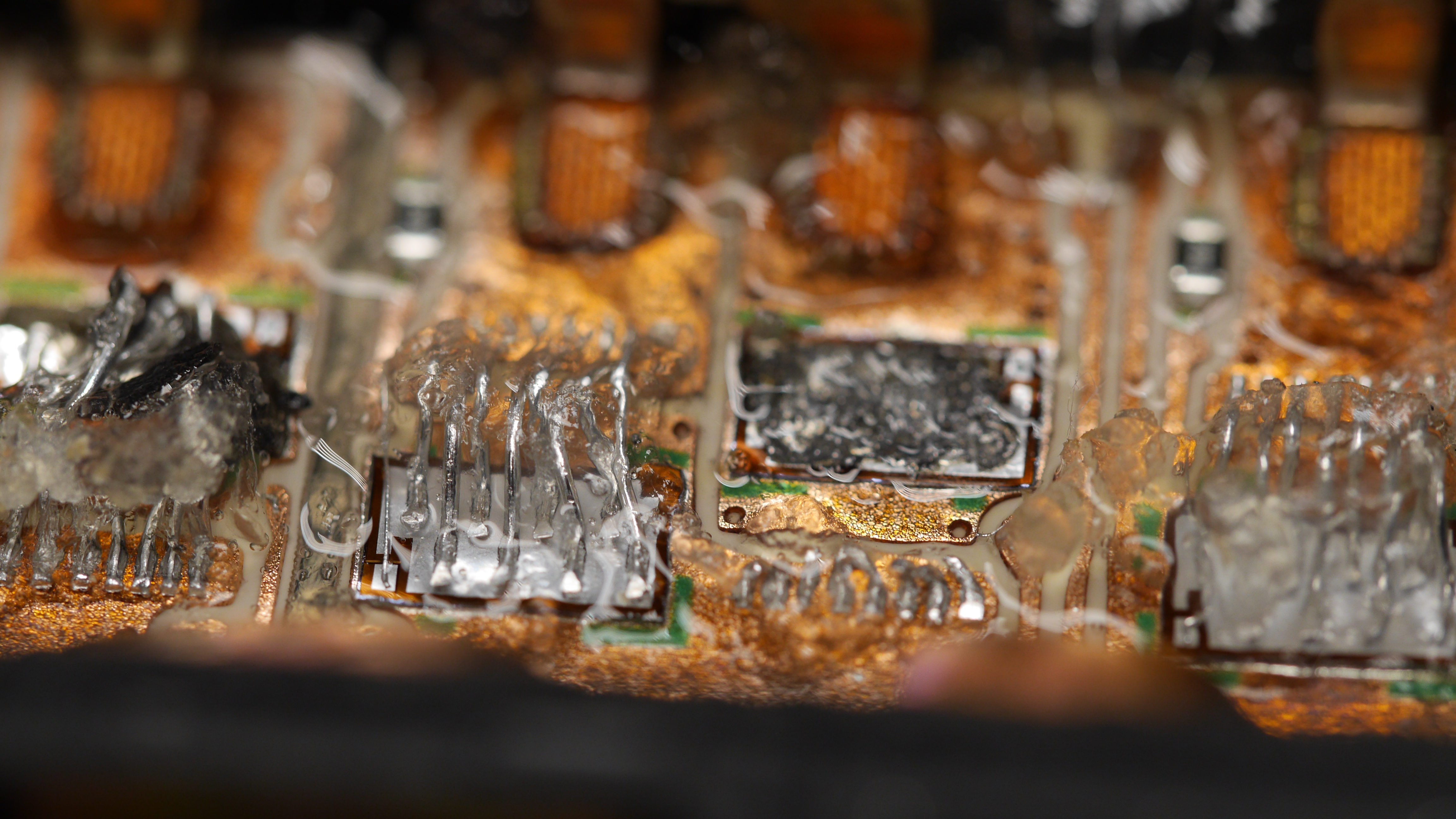
Here's a dimensioned image of a working mosfet. Given the bondwires, this is actually not too-weird of a mosfet. We have no idea what the ratings are but the package construction sure looks like almost-to253. Ideally I'd like grind off the sad silicon to get to the copper underneath and reflow on a solder-able mosfet. 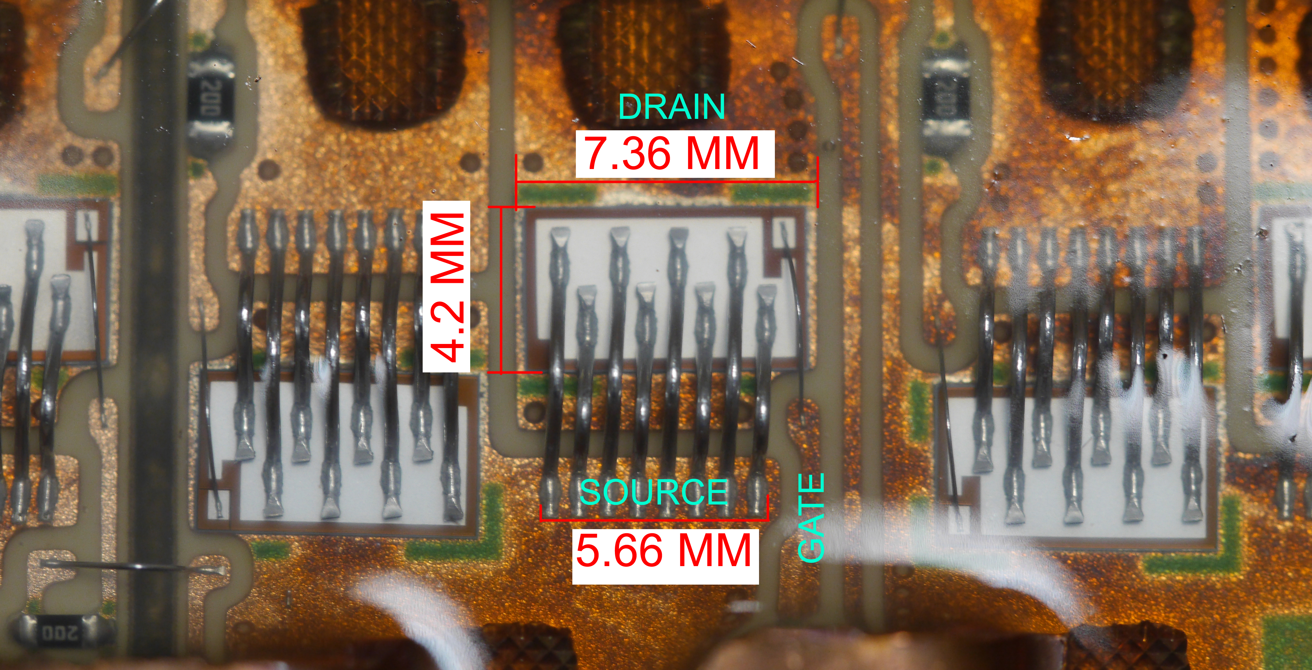
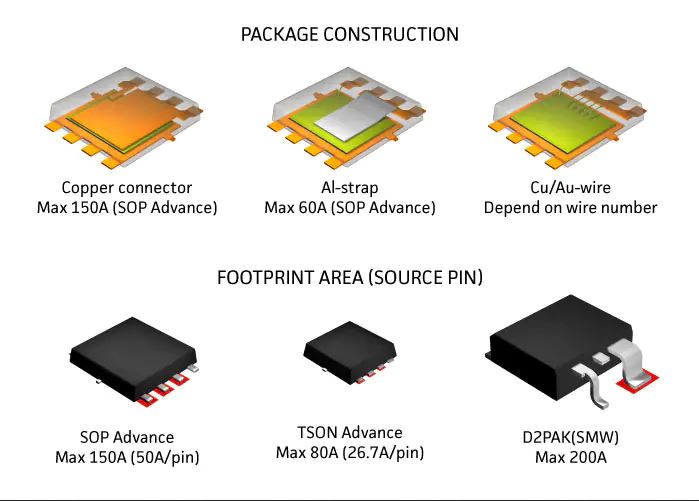
Assuming the silicon that's somehow bonded to the underlying board is removable, we need a package that can sit down further leaving the actual drain soldered to the pad tied to the bus-bar and having the source / gate re-flowed onto the bottom. Our candidate for this is Toshiba's U-MOSVIII-H series, or really *anything* that's 8-PowerVDFN footprint that can handle the current. For a first-test I'm going with: a TPH2R608NH [link]. This is a 150A (max) 75V Mosfet. Its likely a bit under-rated current wise, but for whatever reason higher rated current silicon are a bit missing due to the ongoing chip shortage saga. I chose 75V fets as the battery bus voltage max is ~53V, and using a 60V mosfet would be a dangerous game, due to lack of voltage headroom. Maybe the on board silicon is actually 60V and these failed for that reason. Replacement mosfet modules?!In a wild twist of fate, this issue is so common that the guys at MySupercarExpert has released repair modules. I was planning on generating something myself but this is amazing. Clearly this problem is more common than I had expected. Given that two of the motors I purchased from ebay had both the lower mosfet modules blown, this has to be a frequent issue. This module is a work of art!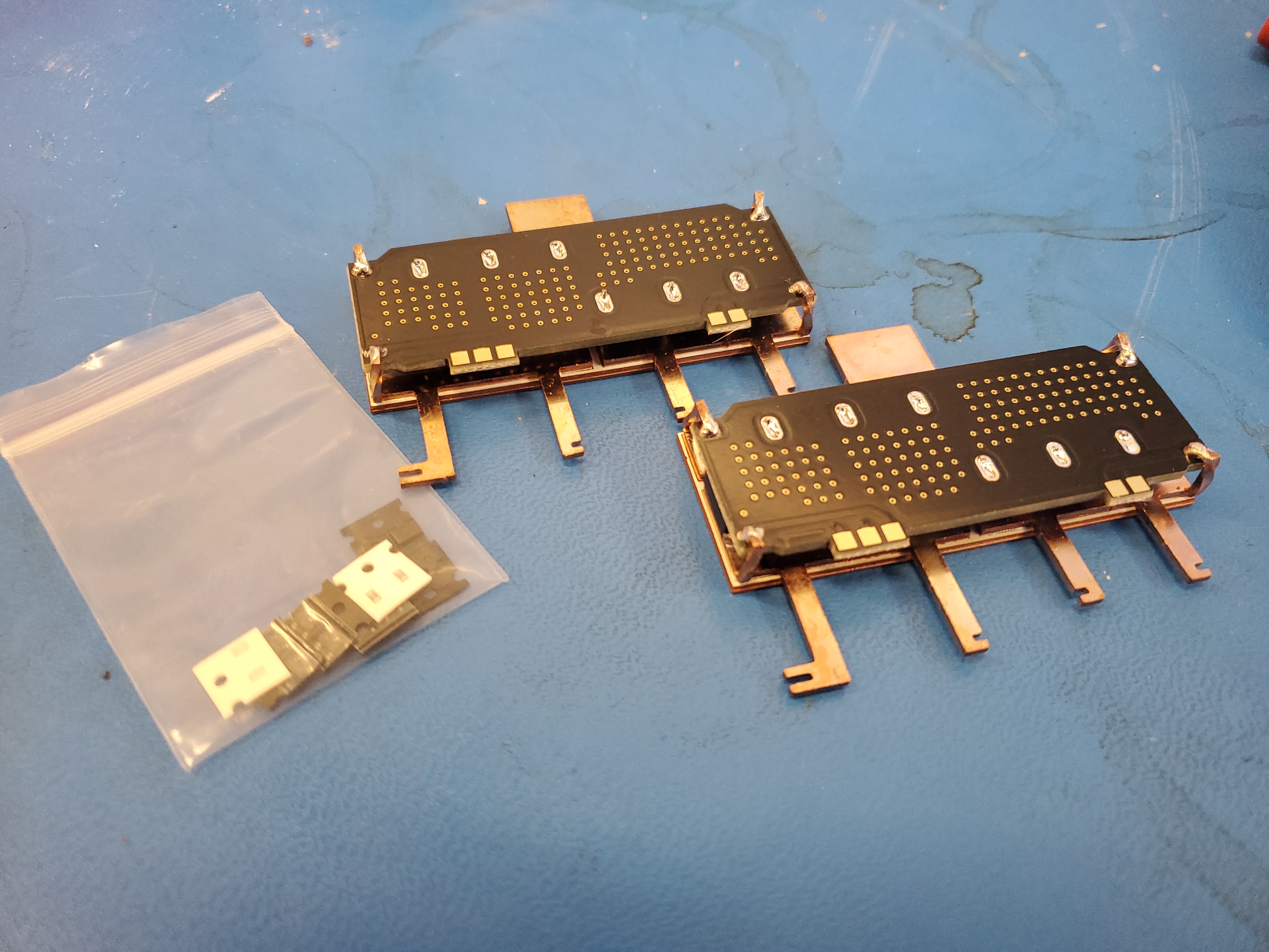
With the rear cover of the controller off, all three phase h-bridges are visible. They are covered in a solastic gel to provide some kind of electrical protection. I used Gaffers tape to cover up the two phases that appeared to be in good working order. As all of my motors have blown half bridges, it was time to cut out the failed parts and install replacement modules. This process is a bit messy. The first step was to disconnect the motor phase busbar from the pcb. I used a dremel, and taped up all other parts of the motor controller assembly. Motor RPM Tests with internal controller
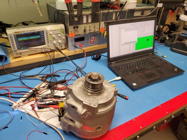
With a lot of debugging, here's one of the first spoolup tests. One thing to note here is that I am not using a strobe / optical rpm meter. I've found them to have alising issues and generally be somewhat questionable. This rotation-meter was verified to match up at 2k rpm on a nearby lathe with a working DRO. We'ere seeing 14K + rpm at 45V input, which is not actually the intended battery configuration. |
Have you noticed that there are no
advertisements or ridiculous pop ups?
No cookie banner or newsletter?
I'm trying to make a better web, feel free to support it.
Want More?
Here's a behind the scenes look at my work space and some of the images that did not make the cut to be included in the write-up:
If you have questions or comments, ask below or send an email
Post your comments! |
|
Comment Box loading
|