
Dane Kouttron
This project / write up is in progress, check back for more soon!
Project Started: 12/2023
48V Hybrid E-Torque Automotive Motor Generator Reverse EngineeringJust like the 48V Audi and Jeep Altermotor project, we have a new contender, a 12V Hybrid motor? Lets take a look and see if we can wake up this gadget. Is this the new small 12V go kart propulsion system in a box? |
|||
Some Project Background:The e-torque system is a variant of 'belt alternator engine start-stop' hybird, where the electric assist motor lives in parallel with the ICE engine. This is one of the first common 48v hybrid, which is incredibly exciting. There were two vehicles initially supporting this route, the 2019-2021 Jeep Wrangler and the 2019-2022 Dodge Ram 1500. This beautiful device was born in late 2018. Its a liquid cooled induction motor with a built in inverter, its automotive grade and its presently fairly low cost on the used / surplus market. Just look at that thing. Its gorgeous. Have you purchased a hobby BLDC outrunner, and found that it exploded under load? Whats the half-life of hobbyking? While this is no where near as lightweight as a 7kw outrunner, it is comically ruggedized and has an actual coolant jacket. Behold the savior of electric go-karts, I bring you the e-torque. 
Here it is, quite adorable. The motor consists of three face mounted mounting points, a built in spring based belt tensioner. To translate ~15kw into a serpentine belt you do need to play some tricks. The wrap-around on the belt is nominally the contact area for force transfer. Having a high contact area and adequate tension is very important to get this working. The key 'specs' we know about this motor [link] are: 60Nm of torque, 14-16kw of mechanical power peak and a maximum of 20k RPM. the continuous rating of 4-6kw is curious, but i think this is due to the 'coolant' being engine coolant, or basically 100C glycol-water. I imagine if this was running 25C water the continuous and peak powerwould be much closer. The coolant lines are simple hose-ring-clamp style connections, instead of an obscure quick-disconnect fitting which is nice, but seriously electric motors shouldn't be cooled with 100C water. The motor itself is 'rare', its both relatively high power and low voltage. Its fundamentally difficult to provide continuous duty high power from a low voltage system due to the high current required. 48V hybrids operate at the edge of SELV or Safety Extra Low Voltage [wikipedia link]. This is the safety barrier to having more exotic connectors, insulation gloves and PPE. If you notice most items you interact with, aside from mains AC powered, are 48V (60v) or below, this includes POE (power over Ethernet), USBC-PD and portable power tools. When you push past this barrier from SELV to LV you get into a more scrutinous spot for UL approval when it comes to DC hazards. There has been a huge push for over a decade to move away from 12v ICE automotive power for auxiliary systems and engine start, however it perpetually looses traction due to a number of barriers. 48V vehicles need to be able to 'jump start' a 12v vehicle, so they need to support a 12v system. That jumpstart process needs to be clear, such that the 48V bus is not used when jumping a 12v bus. The real goal of 48v mostly motivated by copper. High current wires are fundamentally expensive, whereas insulation for 48v systems is cheap. A 4x increase in system voltage allows for a 4x reduction in system current, so wires can be smaller and cheaper. Starter motors are the main high current draw for ICE vehicles, pulling upwards of 600A on engine start, and supporting that high current draw for such a short duration is somewhat wasteful. Reducing that cost is visible everywhere, have you noticed a return wire running to the starter motor? no the vehicle chassis is the return path, to save cost. Literally hundreds of amps wrap themselves around the bellhousing to find your starter motor every start, it generates a bunch of odd behaviors on sensitive instruments (analog fuel gauges generally display incorrectly during vehicle cranking). So what controller does this monster use? 15KW at ~50VDC is 300A, what mosfets are they using? Oh baby that is a good question: 
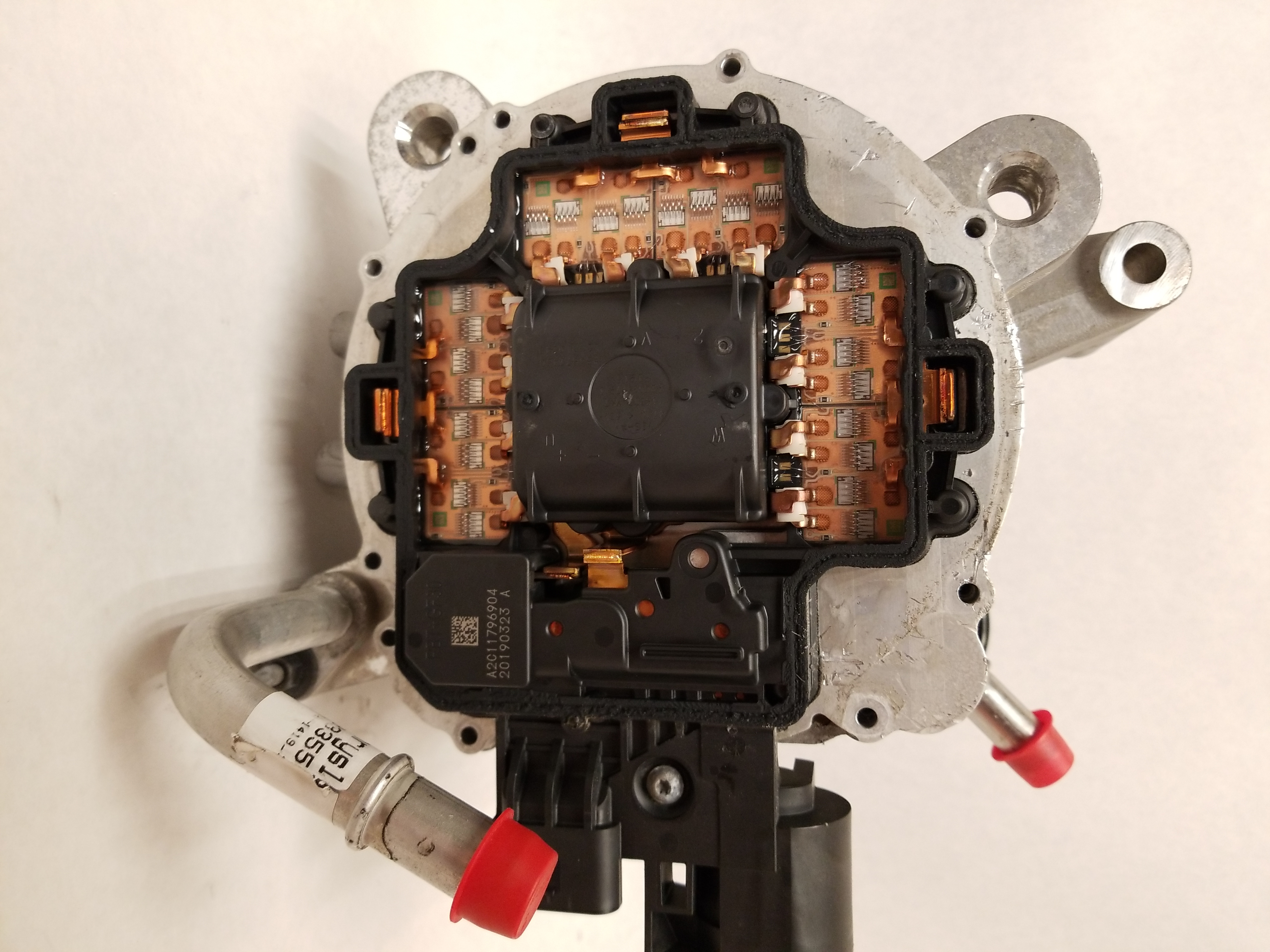
Behind that very very sealed in rear metal case is this masterpiece. I did not have any particular expectation but this is some remarkable engineering. This is a motor controller directly bonded to the moor casing for heat-sinking. You're seeing everything on the power electronics side, a three phase bridge, a central dc-link capacitor and external interface hardware. I will refer to this capacitor below as a 'bus capacitor' as that seems to be the colloquial term for local capacitors for motor controllers. The controller is remarkably compact for something that can pump 15000 watts. lets zoom in and take a look at everything. 
This is a single motor phase H-Bridge, where the induction motor phase is ultrasonically bonded to the motor controller bus bar. At the very bottom we have a custom capacitor module that provides 48V bus distribution for each half bridge leg. This is pretty excellent and is probably very necessary for regenerative current related voltage spikes protecting the onboard fets. We do see some other interesting parts, namely that the mosfets used for the half bridges are directly wire bonded to the substrate that's being used for the motor control power board. The case of the motor is the major thermal path out, so having the fets adequately thermally connected is key. The motor has three stages of H bridges, one per phase and the remaining side is for DC Link input and other hardware. We also see a few bond wires that provide voltage sensing for the center of the half bridge and gate drive for the high and low side. My favorite part of all of this is seeing the normal ~0603 / 0805 gate drive resistors sitting plainly inline with the gates of each fet. Its like seeing a burger king wrapper on the international space station, its so normal in this very fantastically engineered assembly. Lets take a look below: 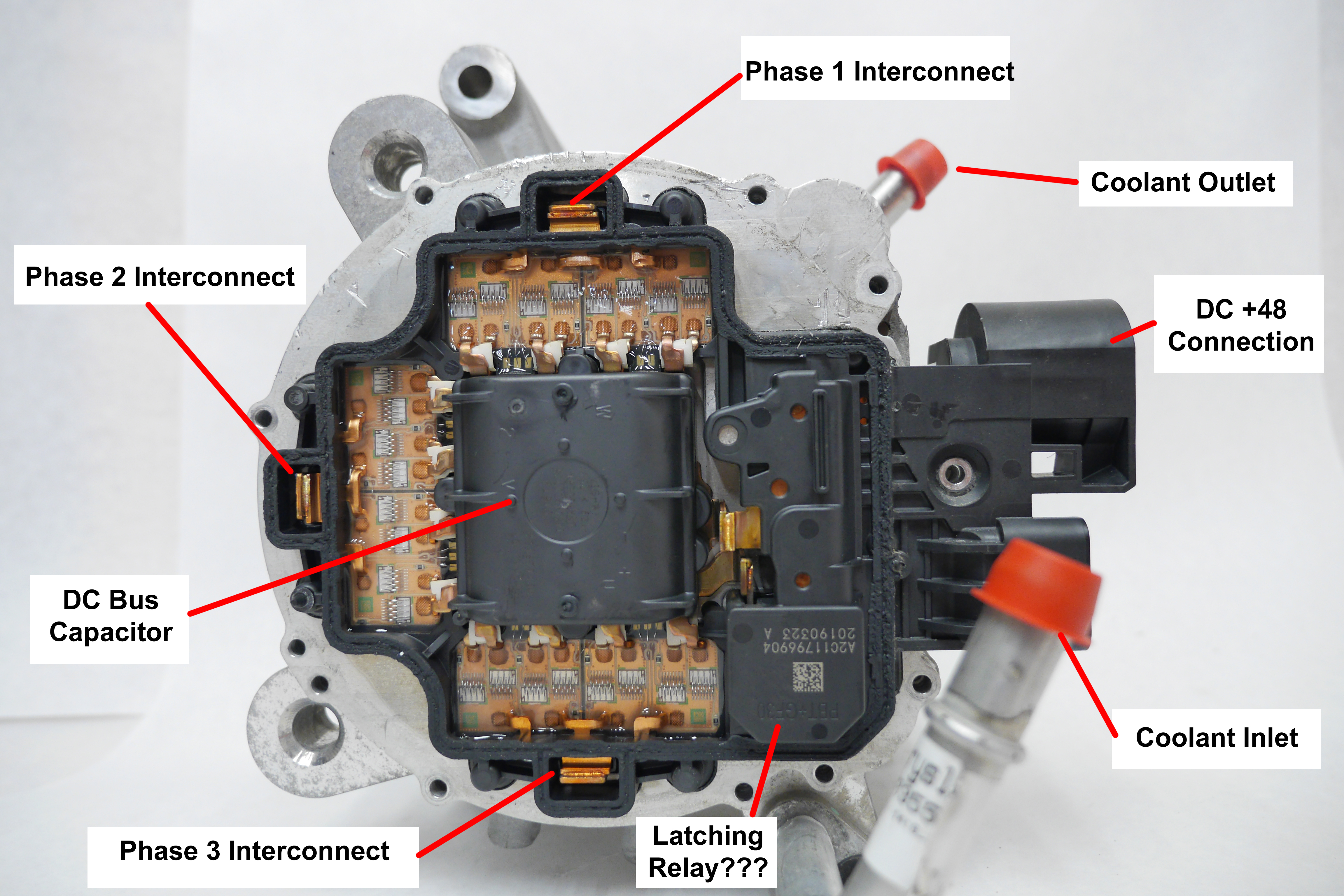
How the DC-Link makes it to the central bus capacitor is curious. The 48V battery link comes in through a stud with a waterproof housing and is then bonded to a bus-bar. Thats where I loose the trace as the remainder of the system is 'potted' in plastic. I've seen a lot of epoxy potted electronics, but this appears to be an ABS-PC injection moulded assembly, which makes it incredibly difficult to teardown. Lets dig into see what else is going on behind the scenes on the remaining side of the motor controller. To disassemble this i needed to heat up the plastic to get a chance at chiseling it away. I used my handy 300W sparkfun hot air gun at various points to try and get *some semblance* of the plastic to soften up. 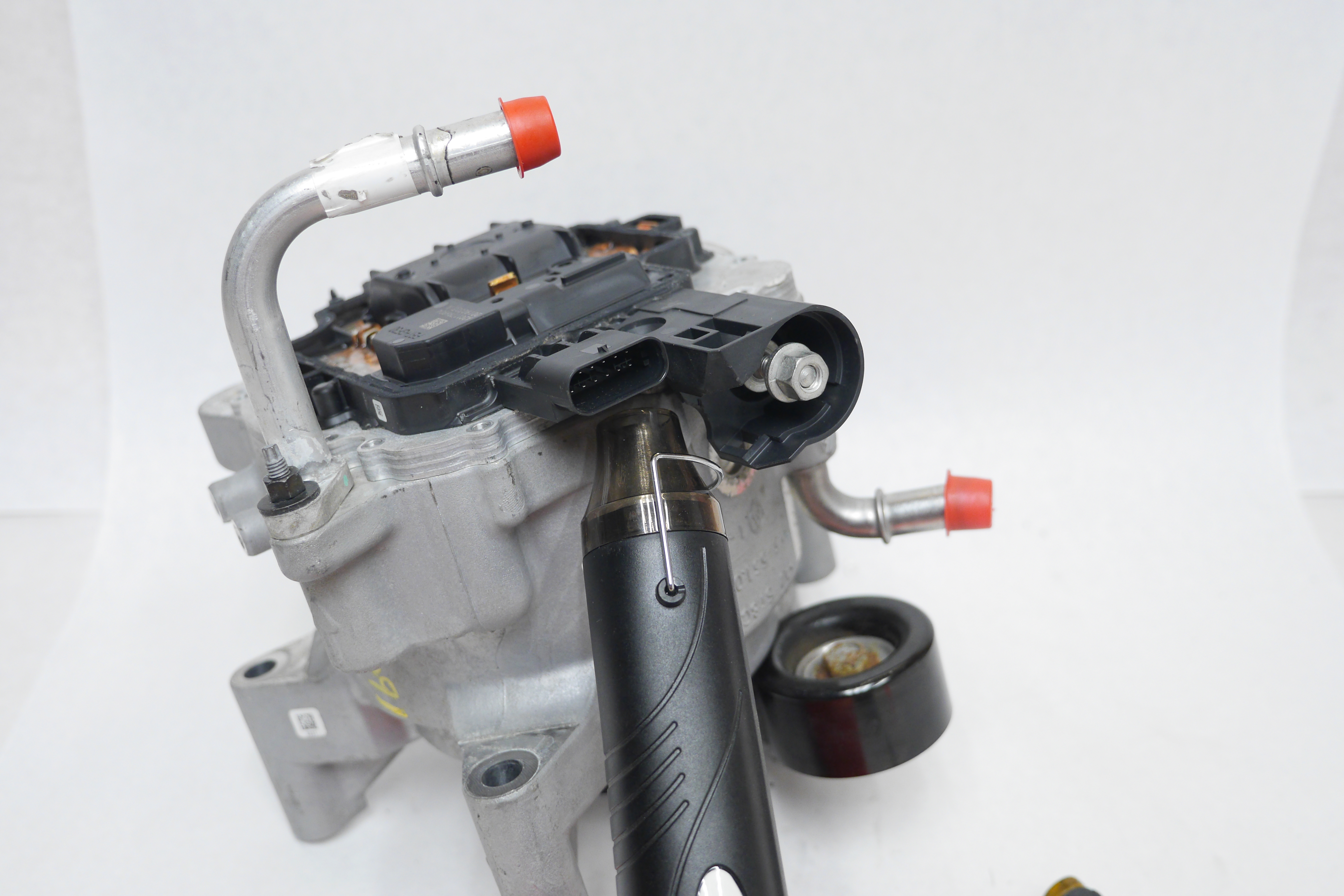
After significant chiseling, and what amounts to an archeological dig, we get a better picture of what is going on here. We know that this motor has to see 300A peak through the 48V feed, so copper bus-bars are used to deliver these amps to the central motor controller bus capacitor. There is a 'mystery box' in-line with the 48V input connection. The main capacitor has two copper bus-bars that appear to be ultrasonically welded to the DC link input. The motor controller (-) connection has to connect to the aluminum case, and due to dissimilar materials, it looks like a stud weldment is used, shown as the 'Case Ground Connection'. We also learn about that central capacitor, which is conveniently labeled. We have a 63V 470 uF capacitor from Vishay. The part number is clearly custom, but we get the important details. 63V is somewhat telling, as that is a standard capacitor voltage. For film and electrolytic the DC 'voltage steps' for capacitors are generally: 35, 50,63,75,100 V and I'm fairly certain these are defined by the thickness of the commonly available separator material. Vishay makes both electrolytics and film so we do not know the internal composition. Given the environment and potential temperature its likely a film capacitor. The voltage rating for a DC bus capacitor is an interesting problem, you maximize the stored energy at a fixed bus voltage when that bus voltage approaches the capacitor maximum operating voltage, however, the lack of overhead results in likely premature failure on over voltage. When you picture DC bus capacitor over voltage its important to think of it as a transient event, and as such the lower the capacitor impedance, the more tolerable it is to that over voltage event. Furthermore the proximity of 'the battery' to the dc-link bus capacitor and the impedance of that link is also very important. If you imagine a scenario where your low impedance battery is physically in the motor controller, the need for a local bus capacitor disappears, as the path for transients is short and readily soaked up by the battery. 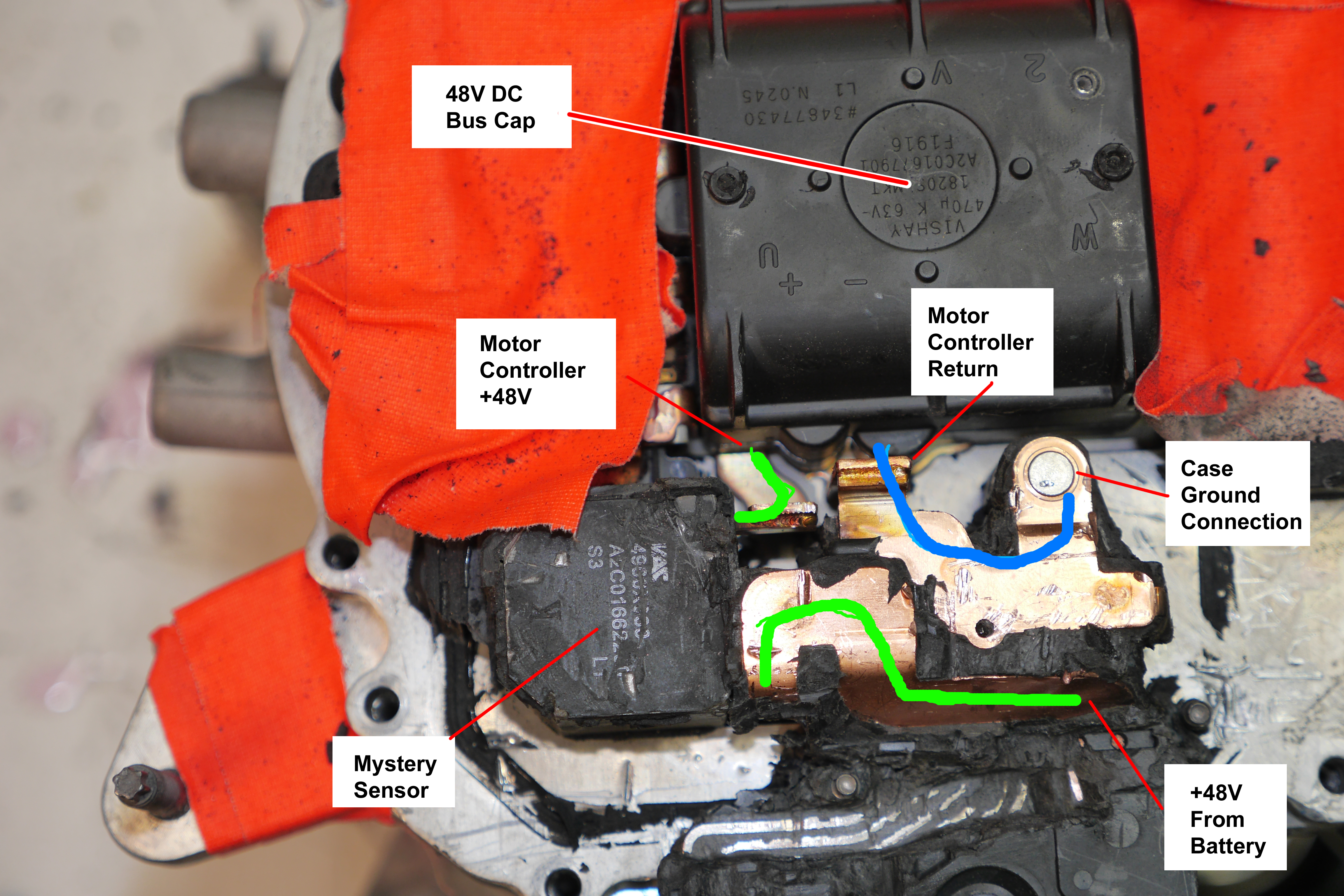
Initially, a 63V capacitor seemed low for a '48V system'. Conventional '48v' lead acid systems have a fairly wide operating voltage. If you picture four lead acid '12v' modules in series, you end up with 14.4*4 or 57.6V, awfully close to our 63V limit. This is not a lead-acid system, so lets do some quick math to verify that statement. The main battery is a 13S (13 series cell) lithium ion pack, so 4.2*13 = 54.6V is the maximum battery voltage. Its unlikely in an automotive application the cells are charged to 100%, as that generally reduces cycle life, as such its more likely this is a 4.0*13 = 52V battery feed. We have a 11v overhead, which is less than ideal but not as terrible as initially observed. Can we sort out who our mystery sensor is though? I chiseled out more of the three dimensional bus-bar routes to try and get a better hint. The only decipherable part of this was the VAC logo, which is from Vacuumschmelze, which sounds like a Justin Roiland auto generated planet, filled with vacuum cleaner people who use humans to clean the floors. 

Vacuumschmelze Appears to be a magnetics company, so this could be a very bizarre common mode choke, or a current sensor. I was mostly concerned that this was a relay that would need 'enabling'. The closest part I could find from their catalog is this [link] 100A current sensor. Its interesting but a keen eye would notice that the initial picture showed a different part number, it turns out that this is an over-mold, the vac part number shown below. If this is a current sensor we do need to patch some output signaling to the control board, 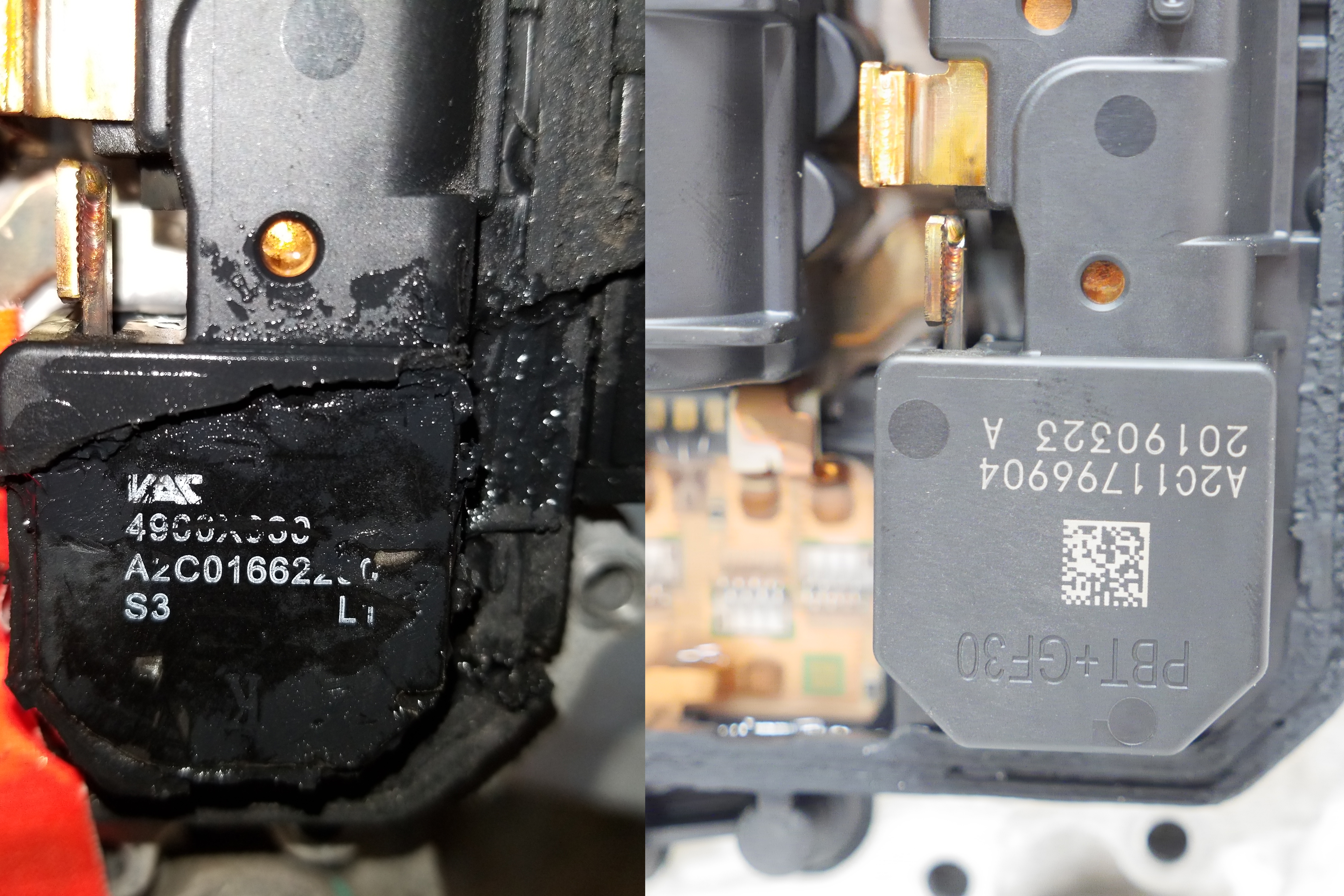 Now that we have detailed parts of the power electronics lets open the lid and see who is driving this bus. Removing the back cover was not trivial. The large green PCB was actually inside of a plastic case ultrasonically welded to the back plate. After prying that off we have a lot to look at. First glance we see the beautiful induction motor windings are actually more like welded together bus-bars than windings. They culminate in three thick copper bars that protrude thru the back of the case and get welded to the motor controller. We see the motor shaft with no visible 'encoder' or resolver just sticking out of the back of the casting and finally on the far side two D-Shaped o-ring seals for our coolant pass thru. The coolant appears to focus on flowing into the back of the motor for keeping the electronics 'cooled'. Its not apparent if the coolant actually cools off the stator windings. As this is an induction machine there are no magnet temperature limits and we're mostly at the whim of how warm the electronics can run. 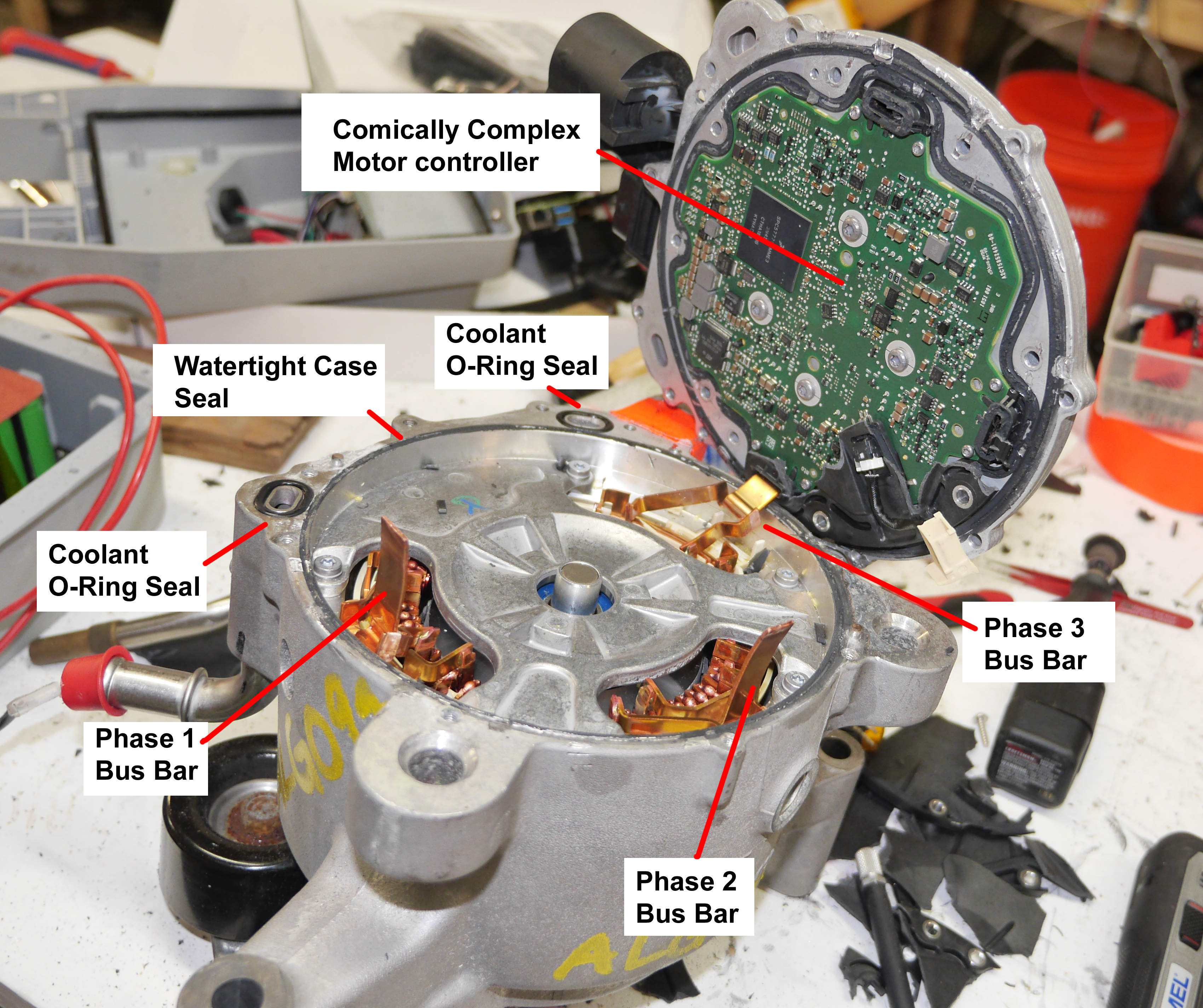 Lets get back to that board, that is a very dense board for a three phase induction motor controller. Its a motor why is there so much hardware? Here is to the best I can discern, everything that is on this board. There is *a lot* of stuff here, and some things that I couldn't identify. The full resolution photo is probably a bit more helpful but we have 'a monstrosity' of a main controller. For a short moment i was hopeful this would have been an STM32, as throwing together some FOC control for an induction machine would be a really interesting project, unfortunately this is an NXP monster-truck and more of a CPU than a micro controller [link to part]. Furthermore due to its size its unlikely to find a footprint compatible easier to program part. 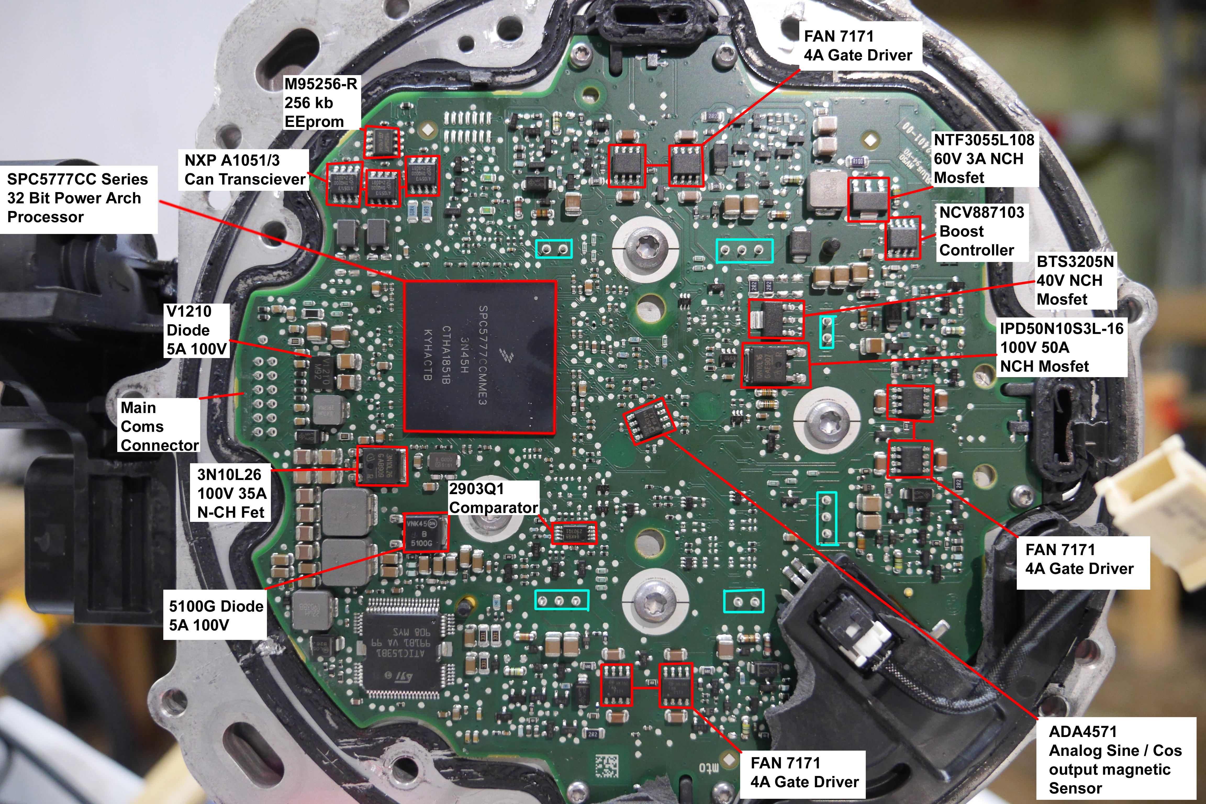 There are so many questions here, why are there Three separate can drivers. Starting from the left, we see one of the major interfaces to the outside world, our 12 position automotive connector. This is a non-soldered press-fit connector. Press-fit works well for ease of assembly but I've always been wary of them working over time as the tolerance requirements in a vibration environment are a recipe for a bad time. Next to our input connector we have some input EMI hardware and what appears to be local power supplies for a 3v3 and 5v rail. We have a mystery chip on the bottom left but as we go up we run into... Three can transceivers. I did a double-take when I saw this as its unclear why that would be necessary but continued on. Each of our half bridges gets a pair of 4A bootstrap gate drivers [link] one for lowside switching and one for high-side switching. These normally use a 15V rail but could be run with 10v for the gate drives, highly depending on the H-Bridge power mosfet used for the three phase drive. We do see an ADA4571 analog sin-cos magnetic rotary position sensor at the very center of the board, interestingly placed at an angle in relation to everything else on the board. This likely grabs the magnetic field of the rotor for slip angle estimation or whatever control topology they are using. To verify my hypothesis we can see that the motor's rotor does indeed have a two-pole magnet on the end. Induction motor rotor estimation is less critical than PM brushless motors, and given that this motor may exceed 15krpm a small pole count is probably desirable.
How are they measuring phase amps? That's a good question, there's a small (hard to read the label) analog hall sensor sitting inside a ferrous bus-bar pass through that I believe is working as the phase current sense. This is remarkably compact as the next best option would have been a LEM module or equivalent. Really awesome work here. 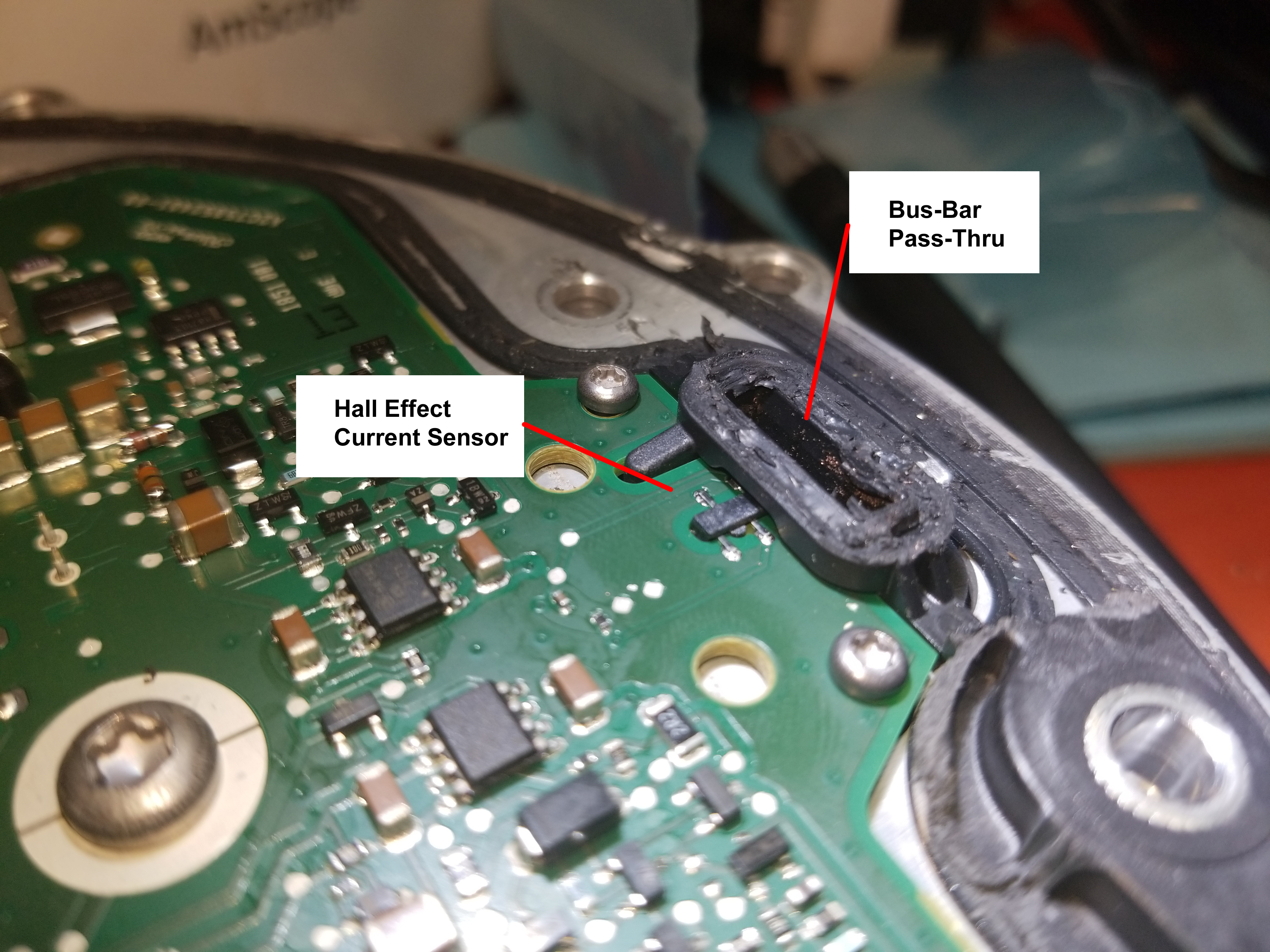 Lets take a quick step back & see what information there is online about this motor The motor was designed and fabricated by continental, we get some basic details from this presentation by Steven Kowalec [link][local copy]. At first glance we learn that there is a bidirectional 12v supply in the 48v battery module, and that continental planned on two motor variants, a 50Nm and 30Nm. The 'cooling fluid' temperature is the real kicker, -40C to 115C. 115C is not coolant, its hot-ant, so this motor is intended to live on the ICE engine coolant loop. This is starting to make sense, as the 'max peak power' is significantly higher than the continuous power. This differential could be caused by two major things: battery pack limitations or thermal limitations. I'm continuing my wager that if this motor had ambient temperature coolant the 'continuous' rating would be a lot closer to the peak rating, given an adequate battery supply. 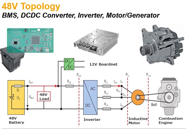 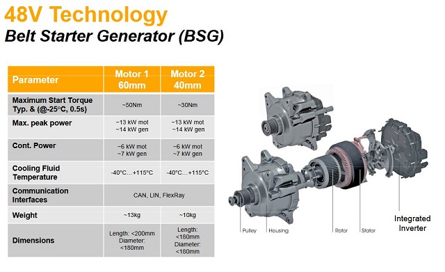 Mechanically, we also get some indication of the internal assembly, this does not give us anything we don't particularly know, but it does show that the coolant loop may wrap around the entire case, which may be counter to what we've observed. 14kw mechanical is the peak power, or roughly 19HP. It will be interesting to find out if this is a controller limit, a battery limit, serpentine belt limit, or a thermal limit. 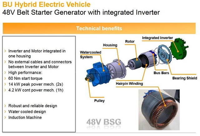 Motor mechanical assembly: Is there anything hardware wise that I can use as a stepping stone for implementing 'Dane Firmware' for this motor? Lets do some more digging. Infineon makes a dev-board thats eerily similar to this motor's built in controller, [link]. This thing is comically similar specification-wise to the 48v inverter on the back of the eTorque motor, and may be the dev-kit it's based off of. Just look at the footprint of the power electronics: 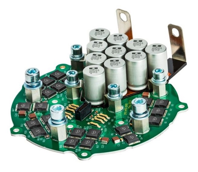 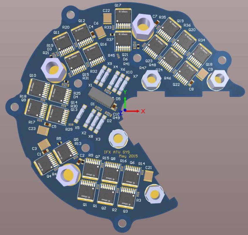 Lets take a look at the specs.
Assembly Footage: Thanks to a German clip from Continental [link] we can see the copper bus bars from the motor being ultrasonically bonded to the power distribution PCB. That little snub that comes down is likely an ultrasonic horn that vibrate-stir-welds the copper bar to a landing pad on the power electronics PCB. Here's an excellent clip of the bar wound stator being laser welded together. The copper bar assembly is pressed into the pre-sleeved stator lamination assembly, an press (not shown) twists and orients the copper bars for weldment and finally an overhead laser connects the busbars together. Step 0: Is there any public data on the CAN commands for this thing No, there's nothing online. There's probably a 'dealer tool' hiding behind some automotive paywall that provides module firmware updates or diagnostics, but nothing public as of 2022. Whats incredibly frustrating is a lot of effort was put into making this, testing this and getting it into vehicles. It'd be curious how far 'right to repair' goes, its probably worth filing a request with Continental and seeing what happens. The probability is incredibly low but how cool would it be to get the design documents or the CAN spec. I gave continental 'tech support' a call in the off-chance they can put me in touch with the right person, and also tried to use the Massachusetts right to repair law to see if I could extract useful data, its worth a shot, maybe I will hear back in a decade.  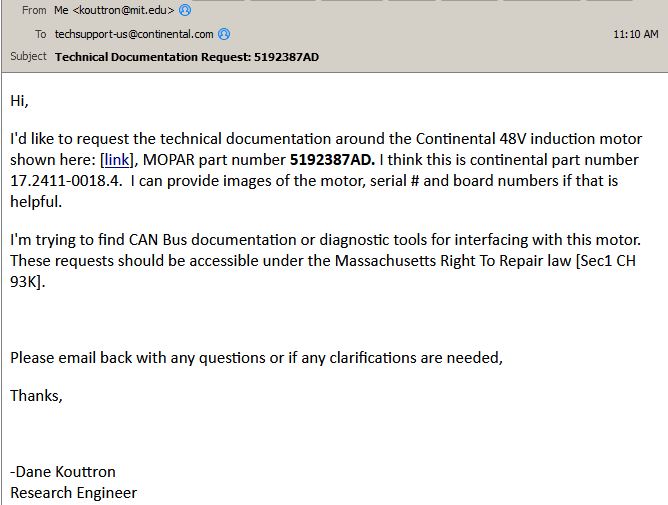 Lo and behold, they responded within a day forwarding me to Vitesco, which appears to be a hybrid vehicle technology company.   The curiosity continues, as the person who wrote the 'Continental' presentation, Steven Kowalec left Conti to head to Vitesco, sometime after the motors were released. If i don't hear back from the main inquiry line its probably time to reach out to Mr. Kowalec and see if there's more info about the motor. 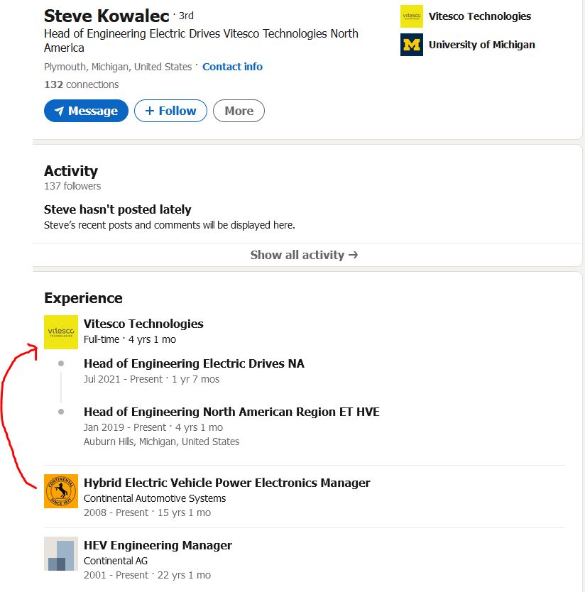 Operation: 'CAN' I write software for this thing Lets take a slightly deeper dive into the 'main microcontroler' datasheet [link], maybe there's a chance I could write a hello-world block commutation program instead of having to reverse engineer the coms protocol for an undocumented 'basically alien' piece of hardware. The main board is unfortunately 'inside the motor' and requires a bit of effort to get to, so this is not a super desirable option. To program this you need to Dremel off the ultrasonic weld that connects the stator bus-bars to the power electronics stage and pry off what appears to be a watertight seal. Not great but without a vehicle to test with, this is an option i can play around with. NXP may have a 'update firmware over can' implementation which, while unlikely, could provide an option without opening up the beast. If this is 'flash-able' we have a chance, if not the only other way to wake up this motor is to rent the vehicle it came from and decipher / reverse engineer its communications. This does have the disadvantage of us not knowing 'what' was implemented. Can you command torque in four quadrants over CAN? at what resolution. For all we know this only has 2 modes, give 100% torque, and take 100% torque. Reverse may not be implemented (do hybrid vehicles even regen in reverse?) without *any documentation* we are just left to make guesses. Step 1: There's a programming header: 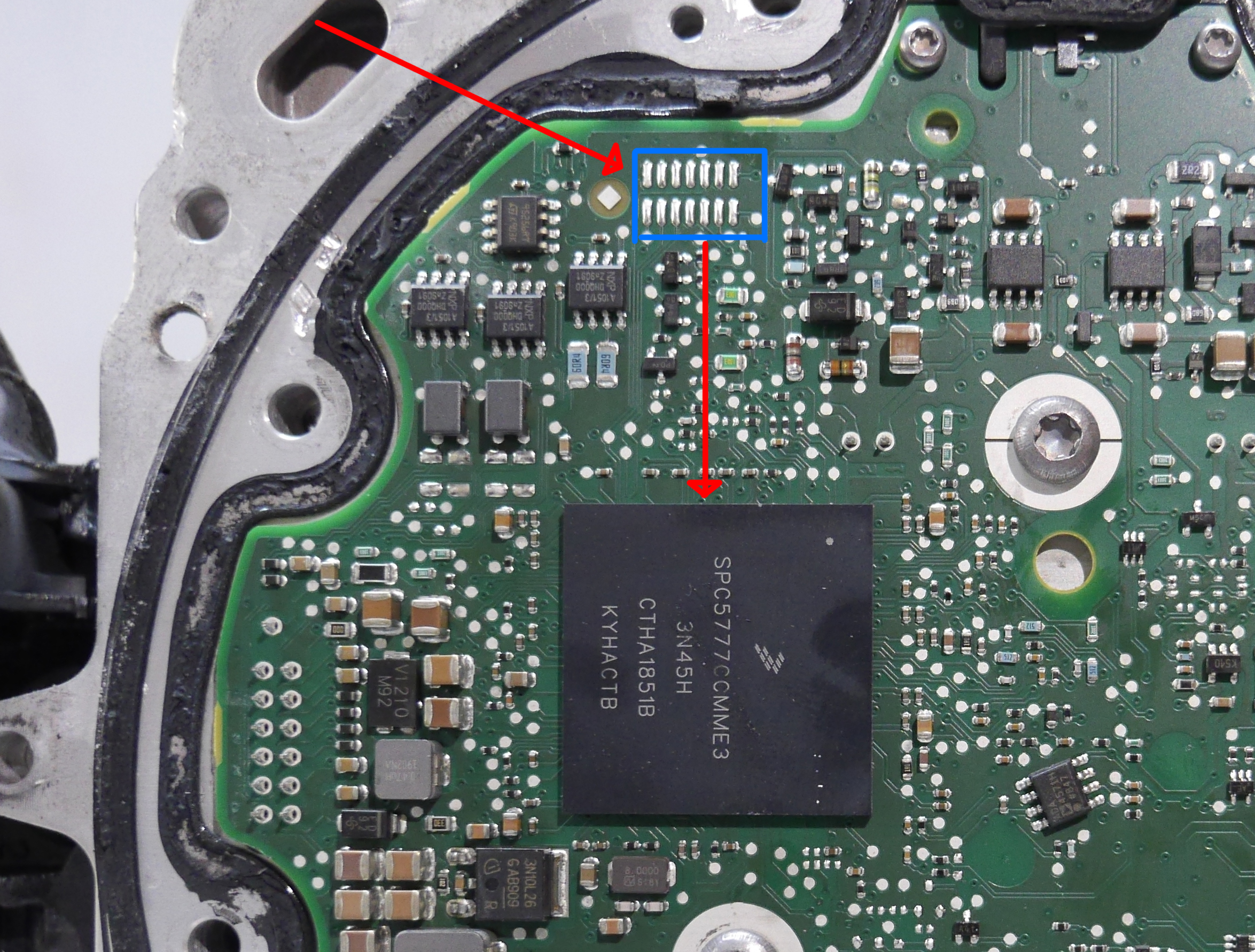 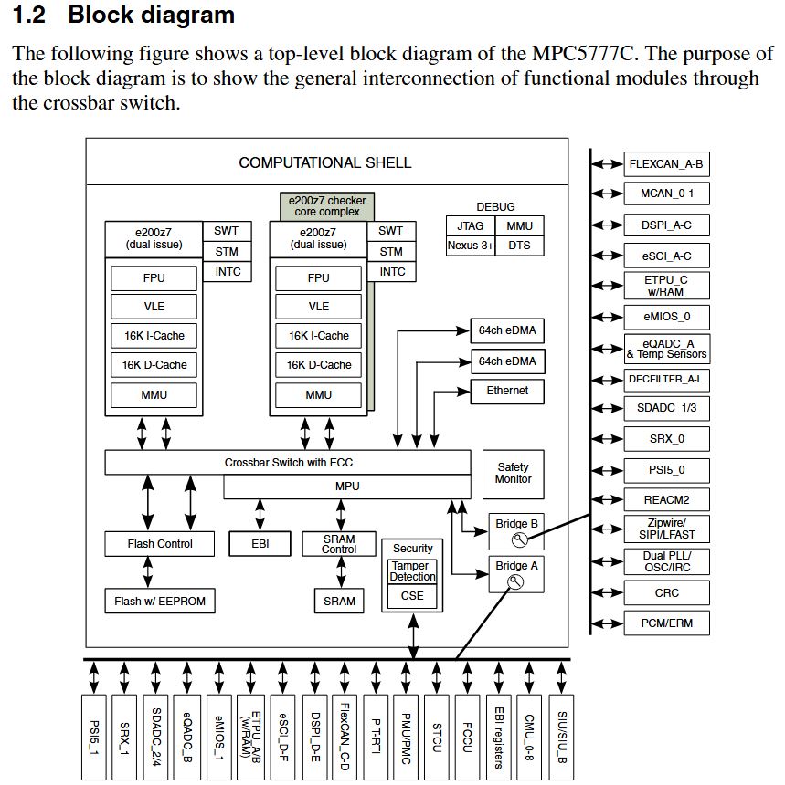 A quick look at the block diagram is a bit overwhelming, this monster has *Ethernet* and somewhat magical crossbar switching for GPIO routing. I need to sort out three main things:
Once these are sorted the next step is
to determine some pin-mapping, ie what port / pin on
the controller maps to gate drive, current sensor,
rotor position sensor, etc. I have a trick for this,
and it toggle the pin at 1khz, and wave your scope
probe over the board to find out the path of your EMI
generator. Ideally whatever is on the other end is not
going to get borked by having 1khz pumped at it. The datasheet gets deeper, this thing
is clocked at ~260 mhz. That was initially eye
opening, but then i remembered the lowly ESP32 has a
240/320mhz core clock. The datasheet references
the MPC5777C Reference Manual, so lets see what that
is. Oh boy the reference manual is... 3393 pages [link]. We
learn some more interesting tidbits:
This seems like an uphill battle at first glance. Not a jog up a 3% incline, more like a jog up mount Washington. Its unlikely this is a purely from-scratch design, any chance there's a dev-kit or app-note this was copy-pasted from? We have a candidate [link]. The DEVKIT-MPC5744P looks like it is in the same 'family', and might provide a stepping stone to waking up its older brother. The devkit is, still available [digikey] (in the era of chip shortages this is a small miracle). Its not BGA, but its probably similar enough where the examples can be crossed over. 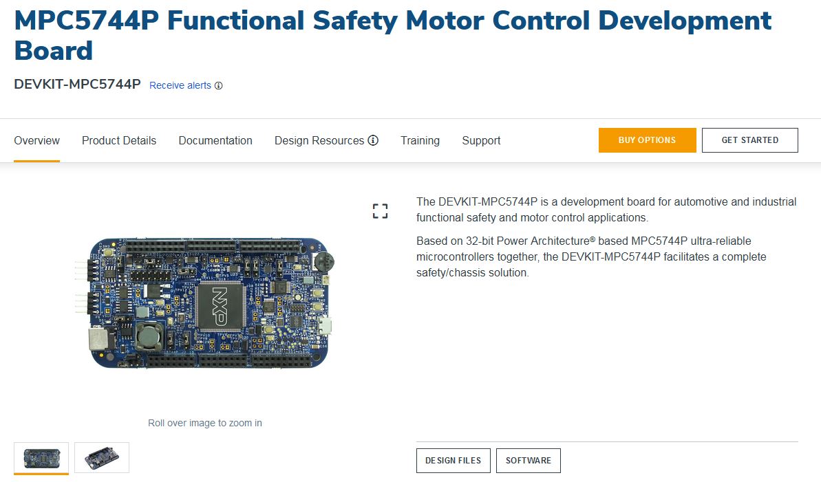 We have a quick-start guide [pdf link] [local copy], lets see what we can find. NXP also has some 3 phase AC induction motor control details, this is looking promising [link].. Some further digging and it looks like the MPC5744P and the MPC5777C are not the same family, they just live on the same planet. The only similar family members to our induction motor friend are: MPC5565, MPC5567, MPC5566, MPC5674F, MPC5676R. None of these have devkits priced <1k USD or physically exist. Neat. Lets try eBay. Oddly this thing came up "ECU Bench Tool KTMFLASH": [link] its some kind of gadget for talking to ECU's with MPC5777C's. Does someone have a gadget that speaks mystery motor? We know that continental (conti) made the motor [link] Operation: Prepare to reverse engineer two CAN Bus's With writing my own FOC induction motor controller deemed 'an expensive uphill battle' the next plan was to listen in on the motor CAN of an operating vehicle. This involved finding a vehicle that i could listen to, and crafting up some hardware (connectors, a cable harness and data logger) to parse the comical quantity of CAN traffic. Three CAN busses is inaccurate, its really two CAN and one LIN bus. Lets make a block diagram from what we've learned so far. This was drawn in Visio, and here's a link to the editable file [link]. 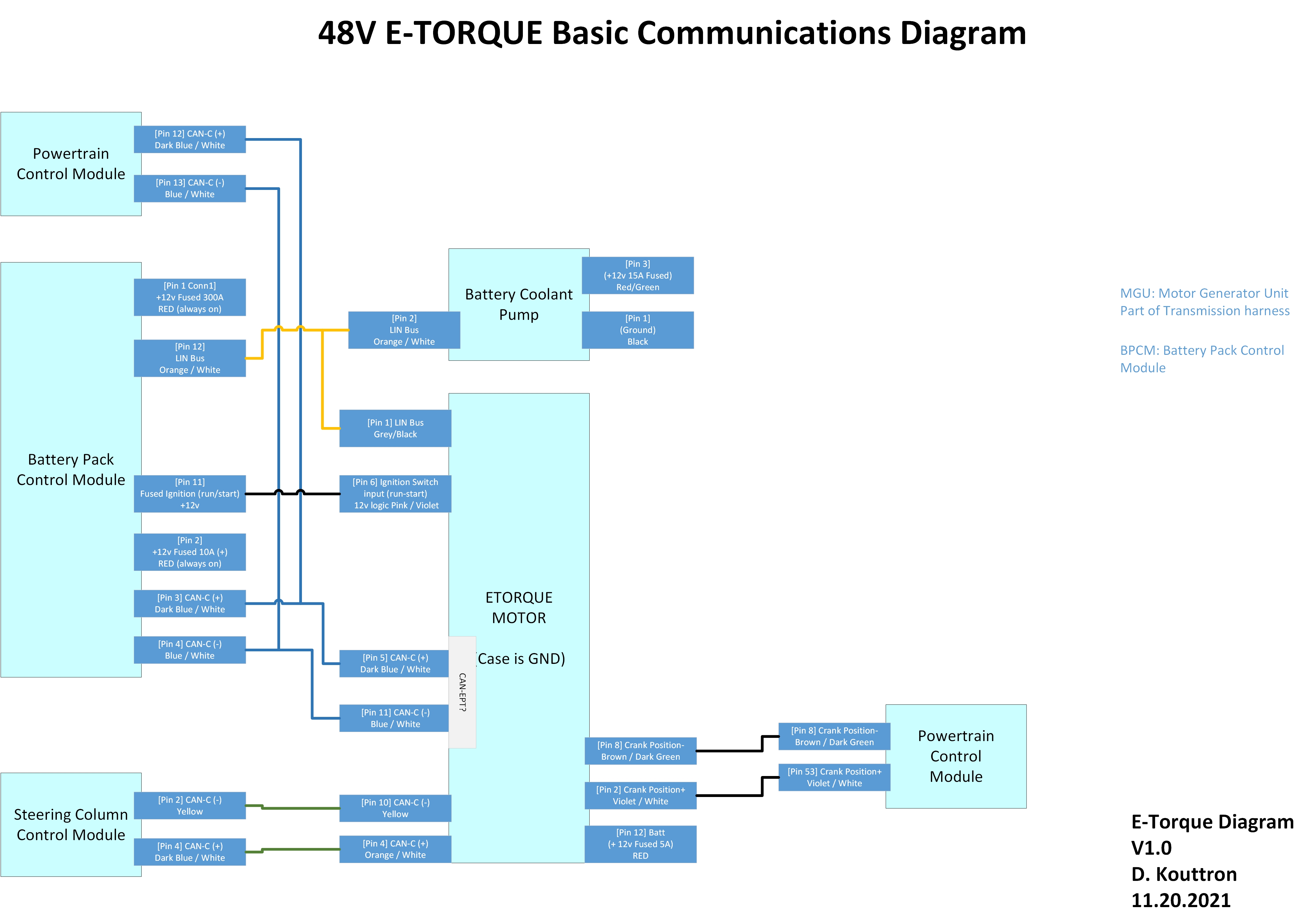 While i'm waiting for the vehicle to be available on turo, lets get more familiarized with savvycan's latest release, and more specifically its 'fuzzing' mode. The motor side connector is very European [link] but it looks like its available from a distributor who doesn't require quantity 50 minimum (250$ minimum) [link] [link] Starting the communications: To wake things up, i had to do a few things: +12v to pin 12, then pin 6 (power and wakeup) CAN+ to pin 4 CAN- to pin 3 120 ohm resistor between the two ground to case. With pcan view connected, at 500kbaud, the 12v power applied we get some communications  I'm still getting the hang of this but it looks like 5 CAN id's are transmitted to the bus at varying intervals: Next up to see what these CAN-ID's actually mean. I headed to Commaai's github, as they are trying to adapt their hardware into multiple vehicles [link]. One of the great parts about comma-ai is that they publicly generate DBC files, or a human-readable description for the information needed to understand a vehicles CAN bus traffic. DBC files can plug into savvycan, to help give some hints as to what they are. Here's some description of the DBC format [link] and [link]. I'm not super familiar with this so lets give it a go. From this [link] Volkswagen DBC we do have some "Motor_Hybrid" notes, but how do we go from CAN-ID to this DBC stuff? DBC is in decimal, can id's are in hex, so we need to convert. "029h" just represents 029 hex, which is 041 in decimal. So we're looking for " 41" in decimal, we get a few hits: Comically, our lookup table is in GERMAN So lets look at 029h -> or " 41" and hybrid and see if there's something useful: "SG" is Signal Definition SG_ ESP_HDC_aktiv : 41|1@1+ (1,0) [0|1] "" Getriebe_DQ_Hybrid_MQB,Getriebe_DQ_MQB SG_ AB_Versorgungsspannung : 41|1@1+ (1,0) [0|1] "" Gateway_MQB SG_ DC_HYB_Abregelung_Temperatur : 41|1@1+ (1,0) [0|1] "" Gateway_MQB Rough translating gets us: SG_ ESP_HDC_active: 41|1@1+ (1,0) [0|1] "" Transmission_DQ_Hybrid_MQB,Transmission_DQ_MQB SG_ AB_SupplyVoltage: 41|1@1+ (1,0) [0|1] "" Gateway_MQB SG_ DC_HYB_Regulation_Temperature : 41|1@1+ (1,0) [0|1] "" Gateway_MQB Welp looks like I forgot this was a Jeep / Dodge part, thats what i get for looking at 2 projects at once. lets check from here: [link] and [link] Interestingly, no e-torque jeeps are on the main spreadsheet, time to find a DBC for an etorque vehicle. A new contender appears: This popped up on eBay, somewhat the bigger-brother to the 48V e-torque. Its awfully similar from the front but has a somewhat larger (possibly integrated controller) in the back. 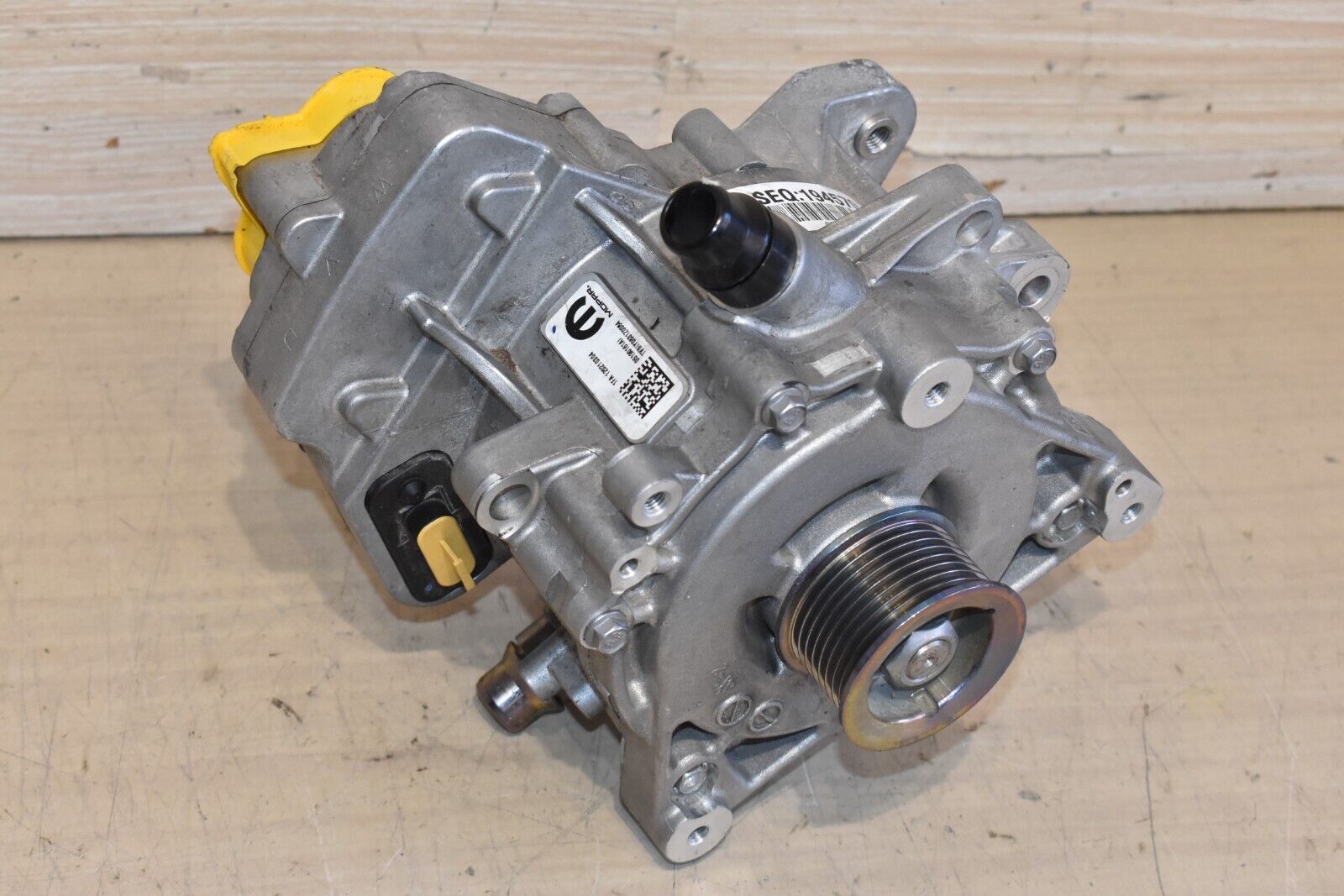 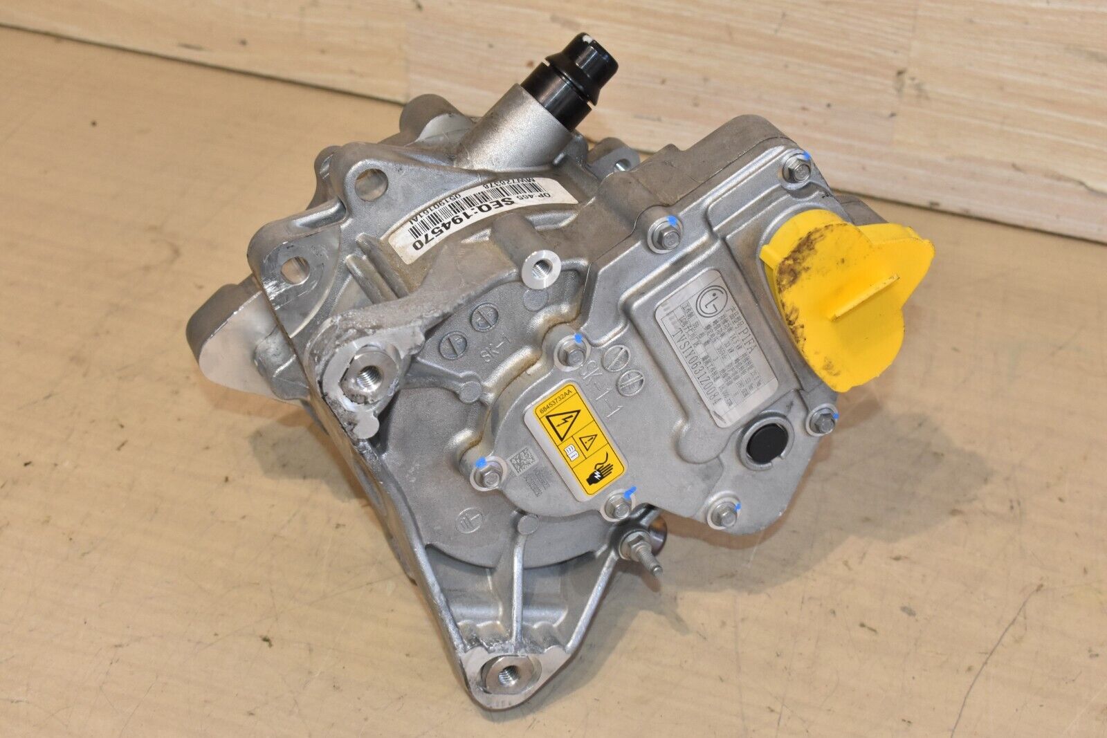 The real curious parts are the ratings visible at the base of this image, if they are to be believed, we have 14.5kw continuous, 33kw peak at 355vdc. Whats odd is the three-prong connector, which would be more of a three phase power lead style assembly, indicating an external controller. It *could* be HVDC and a loopback connection for something downstream but thats somewhat unlikely. 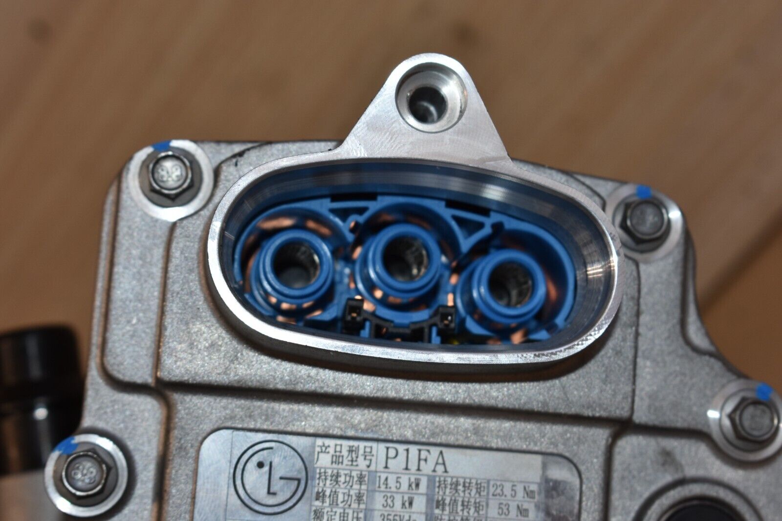 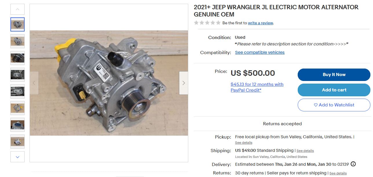 |
|||
| What information about this thing exists [as of 10-2020] |
| What vehicle is
this contraption in? |
 This
presentation from Continental: [external link] [local copy] has some
interesting tidbits: This
presentation from Continental: [external link] [local copy] has some
interesting tidbits: This is page 9,and you can glean a bit of what the nominal setup is. You have an induction motor tied directly to the engine, so no electric-only operation. Interestingly the photo shown has the motor and inverter separated, and looks like it was copied from an engineering diagram, as like I have no idea why phase resistance is included. Also what is a 12v Boardnet, did you mean 12v bus? |
| Here's
some interesting bits. This is slide 12 from
the above presentation There's a 60mm and 40mm motor, both have similar operation parameters. The continuous rating is curious, 6kw in motor mode. Lets take a look at the vehicle to figure out why. Note the coolant temperature is 115C max, which may point to these being used in-line with engine radiator fluid. Having 100C 'coolant' for an electric motor seems inherently wrong, but alas this appears to be what this is designed for. Whats exciting is that it lists -40C coolant ratings, this is norminally to indicate it can survive, canada but, it indicates that there should be no issues with some very cold weather operation on an ice-vehicle. |
 From this presentation [link], from
the 2017 [European Conference on
Nanoelectronics and Embedded Systems for
Electric Mobility] we get a bit of an
internal view of the motor, not terribly
detailed, but does give us a hint at
performance. 14kw peak power [2 seconds] ,
4.2kw continuous [1 hr] seems to differ from
the previous slides, its very likely the test
conditions were with 100C coolant, as 2
seconds is an incredibly short thermal
operating window. From this presentation [link], from
the 2017 [European Conference on
Nanoelectronics and Embedded Systems for
Electric Mobility] we get a bit of an
internal view of the motor, not terribly
detailed, but does give us a hint at
performance. 14kw peak power [2 seconds] ,
4.2kw continuous [1 hr] seems to differ from
the previous slides, its very likely the test
conditions were with 100C coolant, as 2
seconds is an incredibly short thermal
operating window. |
 |
 Can we glean any
information about 48v hybrids from standards? Can we glean any
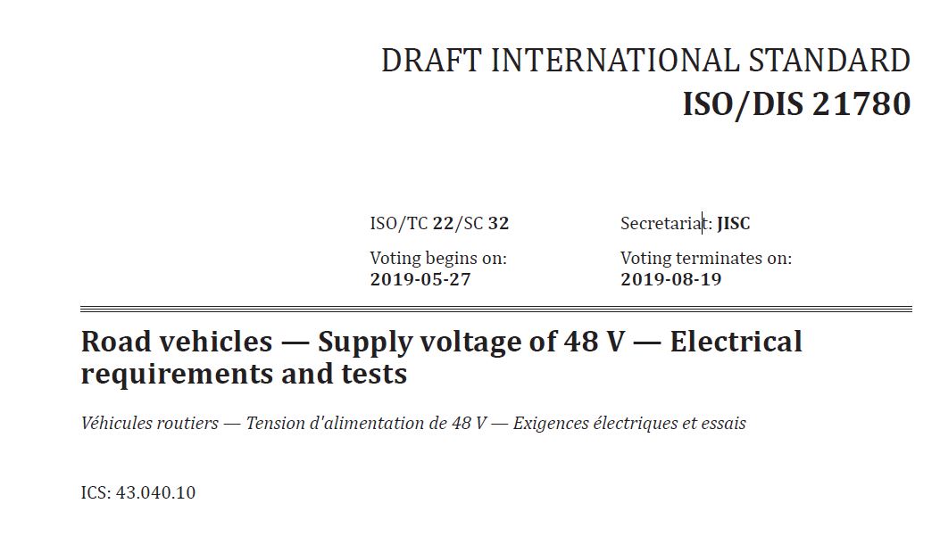
information about 48v hybrids from standards?Enter ISO 21780, this is the 48v vehicle supply specification. I purchased a 2019 vintage draft, while the motor was likely born after this motor was manufactured, but lets dig in anyway. The ISO bodies are incredibly protective of their standards, which for whatever reason cost money. Relevant Ycombinator Post:  So unfortunatley I have to be vague here, from what I can tell, small excerpts are ok. Did you know the bus operating range is defined in an ISO spec? Seriously, 60-58v is the upper overvoltage range, 58-54 is the overvoltage range, 54-52 is the 'you are entering overvoltage range' 52-36 is normal voltage range, 36-31 is the 'you are entering low voltage range' 31-24v is the undervoltage range and 24-0v is the undervoltage limit. This is annoying, I really want to share this specification. Other interesting tidbits, at 40C, the quiescent current must be <0.1mA for the device under test. |
| Does the
2020 copy show anything useful? I had put in a library request for a copy, and while it took a few days, it appeared. |
Interesting
video about the e-torque system on the ram 1500
[link].
|
| So
lets start digging public information which
may help us find out at least the pinout of
this monster. Thanks to the Jeep JL forums [link] there's some interesting wiring diagrams. Unfortunately, this vehicle is a modern monster of sensors. |
 So i did the
thing, I bought the actual service manual. 200$
for a manual for a vehicle I do not own. Neat.
Even more curious, this is a physical flash
drive, so lets see what actually shows up. The
delivery window is ~two weeks, so either it is a
hefty flash drive or its coming to Boston via a
boat. So i did the
thing, I bought the actual service manual. 200$
for a manual for a vehicle I do not own. Neat.
Even more curious, this is a physical flash
drive, so lets see what actually shows up. The
delivery window is ~two weeks, so either it is a
hefty flash drive or its coming to Boston via a
boat. |
| Hardware
Tear-down |
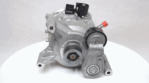
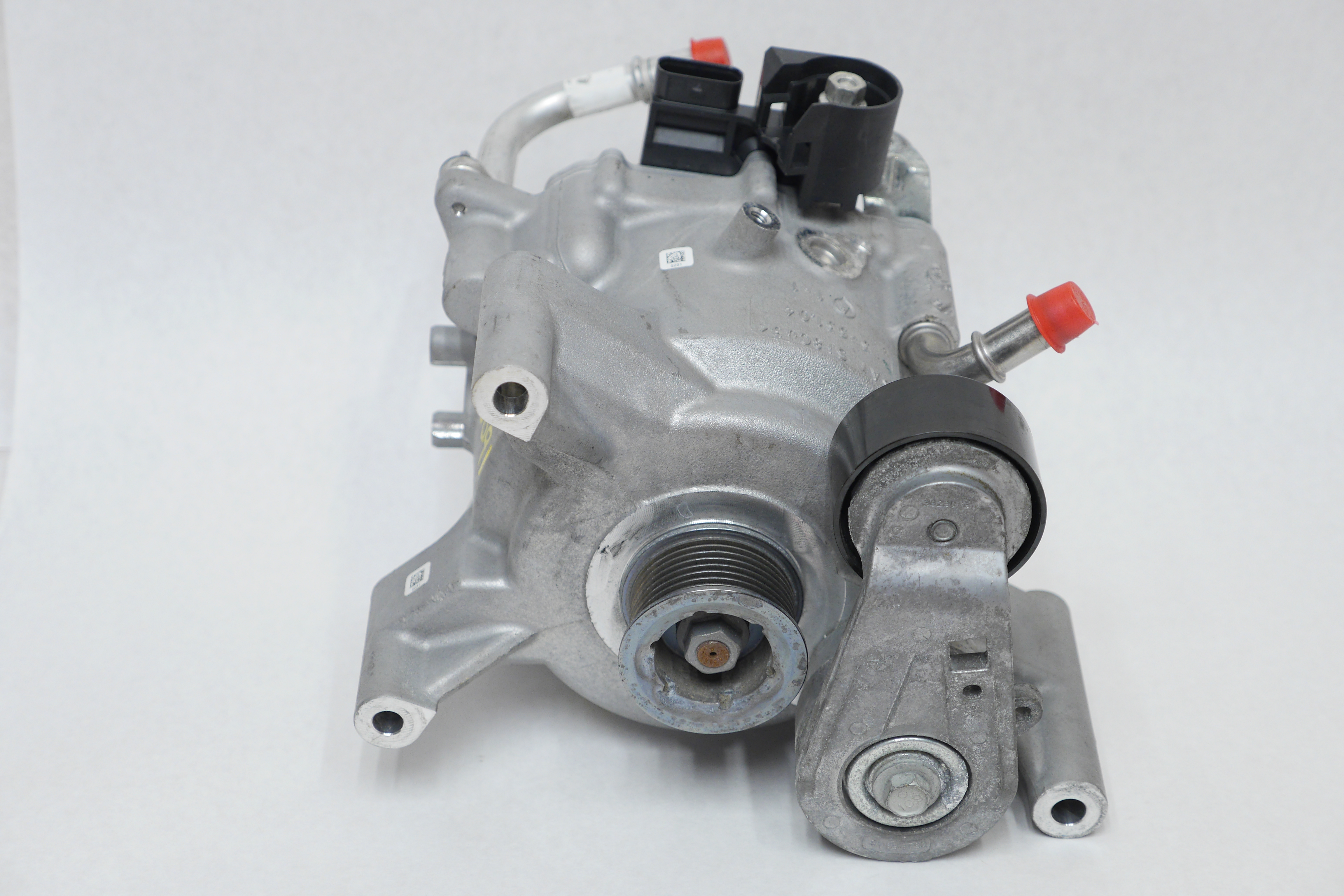 Lets start out
with the first surplus motor, this is basically
exactly as it came from ebay, with two caps added
to the coolant line. Note the pulley tensioner is
in its 'relaxed' state and otherwise has a coiled
spring for applying tension. Lets start out
with the first surplus motor, this is basically
exactly as it came from ebay, with two caps added
to the coolant line. Note the pulley tensioner is
in its 'relaxed' state and otherwise has a coiled
spring for applying tension. |
 the back the back |
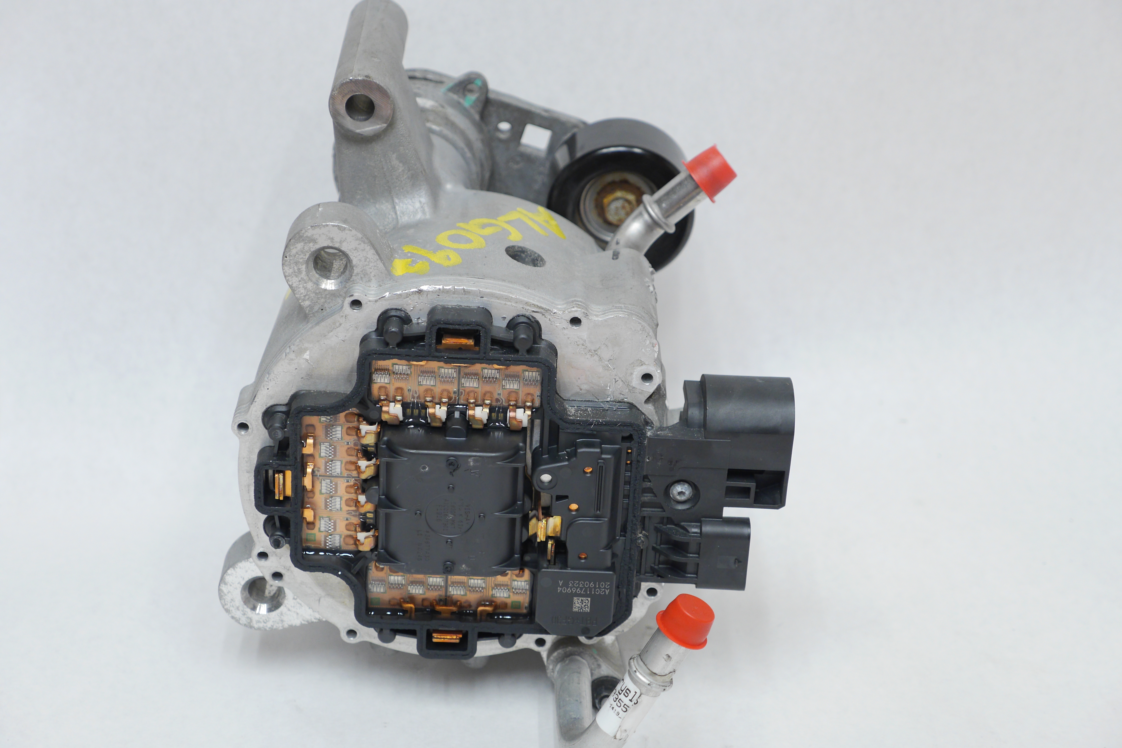
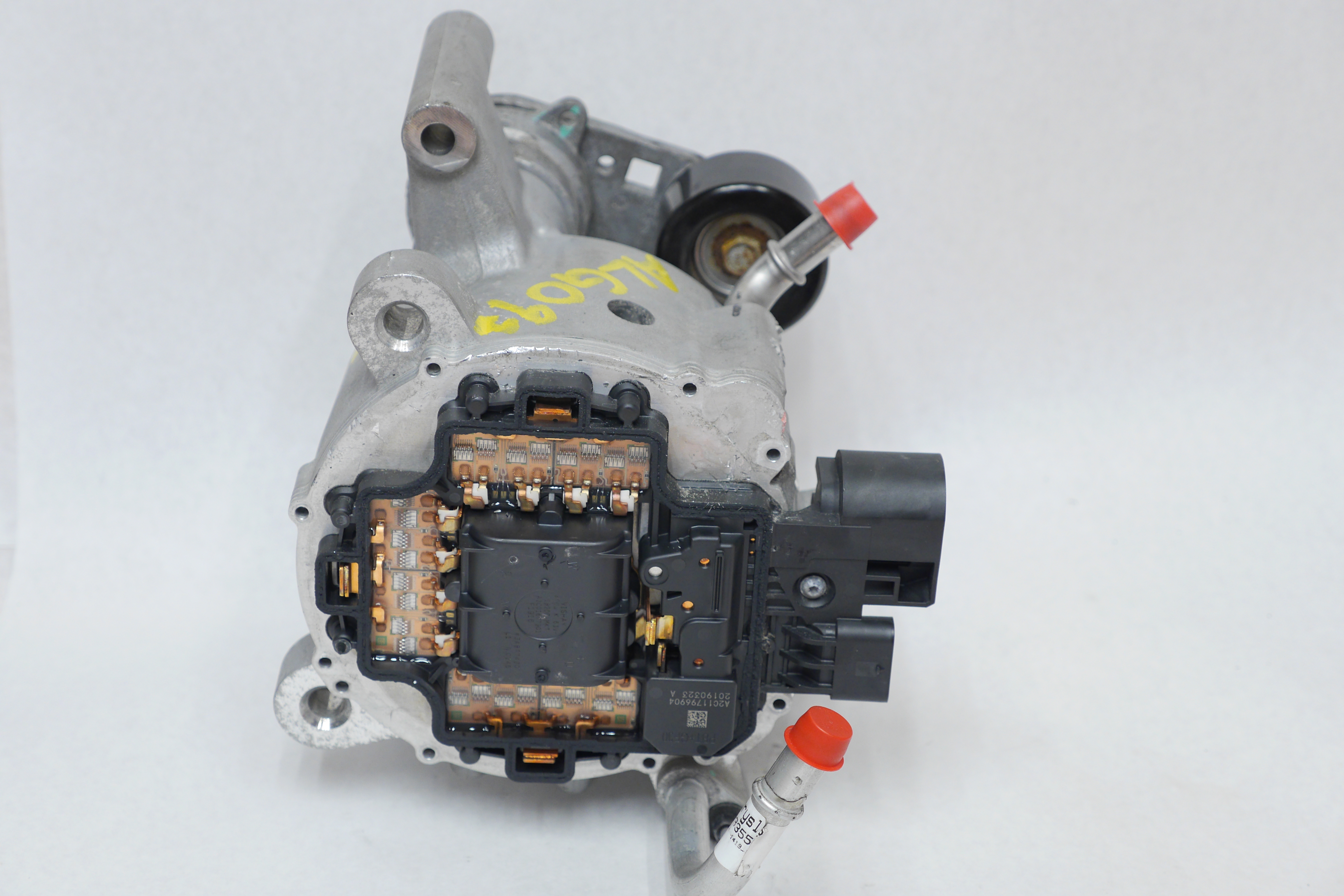 The small plate
cover comes off with a few torx screws, there is a
perimiter seal of some kind of rubberized
adhesive. The small plate
cover comes off with a few torx screws, there is a
perimiter seal of some kind of rubberized
adhesive. |
| Zooming
in Zoomed in we can get a better idea of what is going on, The motor phase connections pop out of the motor case and mate to the motor controls power board with a weldment. This may be an ultrasonic weld, its too clean to be a resistance weldment. Initially I thought the center would be all the controls logic, but then again I've never seen a 'small' automotive motor controller. The blob is clearly labeled with a vishay part number and it appears to be just the DC bus capacitor. Following the 48v connector feed into the power distribution board we hit this, non-descript blob. It has bus-bars going thru it, it could be a fuse but that would be hyper-annoying. I'm going to guess it is a latching relay. It is heavily potted in place. |
| So
here is a zoomed in phase drive This is a really interesting design, the mosfets are directly bonded to the heat-spreader PCB, the motor phase connections are ultrasonically bonded to the PCB busbars and the PCB busbars are ultrasonically bonded to the PCB. For clarity I've labeled the capacitor bus bars that are also ultrasonically bonded to the board. This is wild. Gate drive is wire-bonded to the PCB and silicone gooped to prevent vibration from wiggling them out. There are four separate wire-bonded half-bridges arranged in parallel. The die-size looks like ~ TO-247 sized, its slightly larger than what normally is in a TO-220. The capacitor in the center is incredibly custom. Outlined in blue and green are the gate drives for each of the half bridges. |
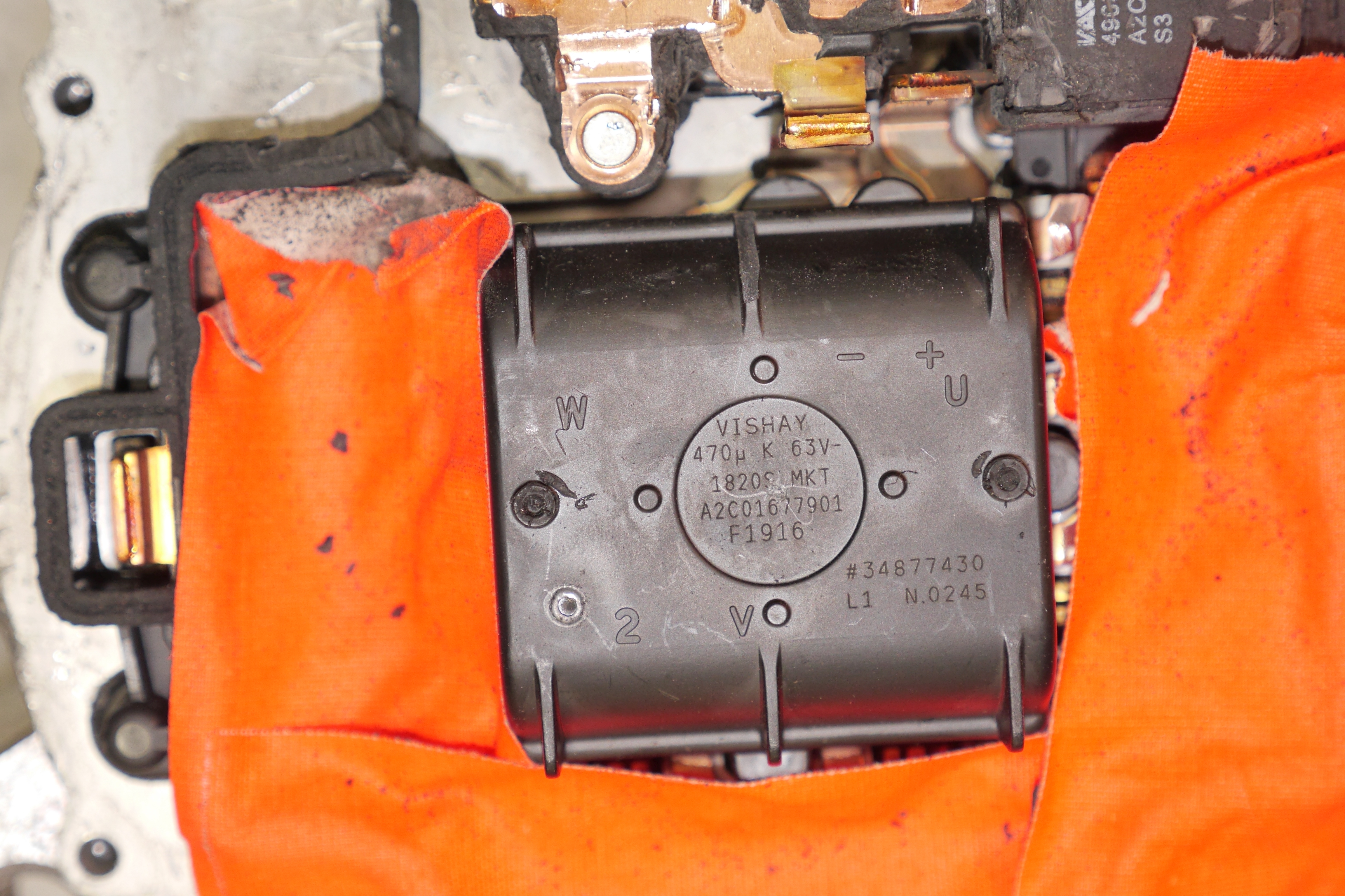
| Speaking
of the capacitor The bus capacitor is a really curious Vishay part. 470uF, 63V. It kind of follows this part series [link] [local copy]. If this is actually in the same family, we learn that this capacitor is an automotive qualified film cap, rated for up to 150C. This makes sense as that cap is in a fairly miserable environment. Its 'cooled' by the engine coolant loop [~100C], its connected to a vibrating engine, and the ripple current has to be fairly high. The whole center of the motor controller power stage is just giant bus capacitor with a fairly excellent bus-bar interconnect. |
| Lets get back
to that mystery 'relay' So the 'relay' overmold part number didnt come up with anything useful,  I began tearing
down further and found that there was another part
number underneath the overmold. 'VAC' is a
somewhat annoying name, as when you look up 'VAC
relay' you get volts ac not VAC.
Fortunately I found a logo: VAC is vacuumschmelze.
Wow that's a name, browsing their website we don't
really see automotive relays, but we do see current
sensors [link]
and common mode chokes. I'm now thinking this is a
big ol' DC current sensor, it could be an
automotive version of this [link].
At least it appears to not be a 'relay' that needs
to be enabled. I began tearing
down further and found that there was another part
number underneath the overmold. 'VAC' is a
somewhat annoying name, as when you look up 'VAC
relay' you get volts ac not VAC.
Fortunately I found a logo: VAC is vacuumschmelze.
Wow that's a name, browsing their website we don't
really see automotive relays, but we do see current
sensors [link]
and common mode chokes. I'm now thinking this is a
big ol' DC current sensor, it could be an
automotive version of this [link].
At least it appears to not be a 'relay' that needs
to be enabled. |
 Ghost
Hunting, the case of the hidden bus-bars Ghost
Hunting, the case of the hidden bus-barsSo with some aggressive chiseling i was able to get to the bus-bar path, its looking more and more like that the mystery VAC part is indeed a DC link current sensor. I'm somewhat surprised the hybrid motor return current is routed through the frame. At 9kw (48v) that's +150A, something is a bit fishy. I guess conventional starter motors are +100A and route power through the frame, so it may not be terrible. Note the orange tape is in shot to prevent debris from getting caught in the conformal coat goo that coats the transistors. |
 Lets
see who's driving this bus Lets
see who's driving this busAfter a comical amount of prying, and grinding away at the welded in copper bus-bars here is what is hiding underneath. The coolant loop on this is ridiculous, it loops up around the back of the case to exchange heat out from the three phase inverter, two oval o-rings transfer from the stator coolant to the rear plate. The control logic is actually hidden under a thermally adhered plastic lid. This was also miserable to remove. The control PCB connects to the motor controller through custom pass-throughs milled out of the aluminum case. There is a ridiculous amount of control PCB here to take a look at. |
| A
look at the big board Here's a direct facing view of the big board. We have a few interesting observations here aside from 'woah this is a lot of stuff to run a motor'. We see THREE can transceivers. Each phase has two FAN7171 4A gate drivers [link], the rotor position is detected with an ADA4571 magnetic hall effect sensor [link], even more curiously its one of those analog sin-cos analog output ones. Finally there is a giant frigging 32bit blob [link] doing all the heavy lifting. That micro is 60$ in quantity 1. This is a monster. |
| Some
interesting design notes: Phase Current Sense One thing I noticed that was curious was how is phase current measured? Given that this is an induction machine, phase current is not as terribly important as in a BLDC device. There's a real weird smt device carved into the board, hiding next to each phase. This has to be some kind of hall effect driven current sensor, its positioning is so incredibly weird to be anything else. |
| Digging
into diagrams |
 Thanks to
jlwranglerforums we have some basic diagrams, of
questionable copyright [link]. Thanks to
jlwranglerforums we have some basic diagrams, of
questionable copyright [link].
To make things less questionable here's my rendition of what goes into this motor. ITS A MOTOR HOW DOES IT HAVE 3 CAN BUSES. h 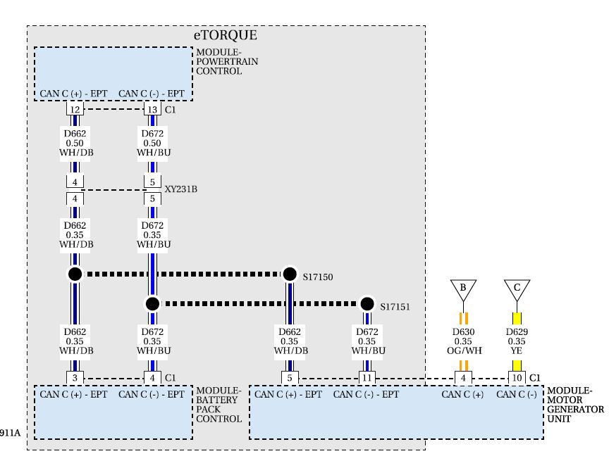 Given that there is a bit of diagramming, i'm going to try and condense things in a somewhat simplified visio diagram. |
| HYPER-SIMPLIFIED
DIAGRAM I made a simplified, readable diagram for what connects to the E-Torque motor. Nominally its not terrible, There's two legs of the CAN-C bus, one LIN bus and then the two very unknown CRANK POSITION sensor inputs. One interesting thing may be seeing what happens when +48v is applied and +12v is applied to pin 12 and then an 'engine start' is applied on pin 6. Its possible it 'just spins for a bit' but I have no idea. Its also not clear why the CAN-C bus loops through the motor. A link to the diagram is available here [pdf]. There are a lot of other things on the CAN-C bus and the LIN bus, but this should be the rough beginning. |
| Here is a copy of
the LIN specification [link]. |
| Lets find our
motor connector |
| An interesting
technical video on the etorque system for
technicians. A local copy is available here [link]
in case this is pulled from YT. |
|
| S |
|
- 48V in this package is glorious,
this is really remarkable motor
If you have questions or comments, ask below or send over an email.
| Comments: |
|
HTML
Comment Box is loading comments...
|
Dane.Kouttron
Rensselaer
Polytechnic
Institute
Electrical &
Electrical Power
631.978.1650
