Dane Kouttron
Project Started: 03/2024
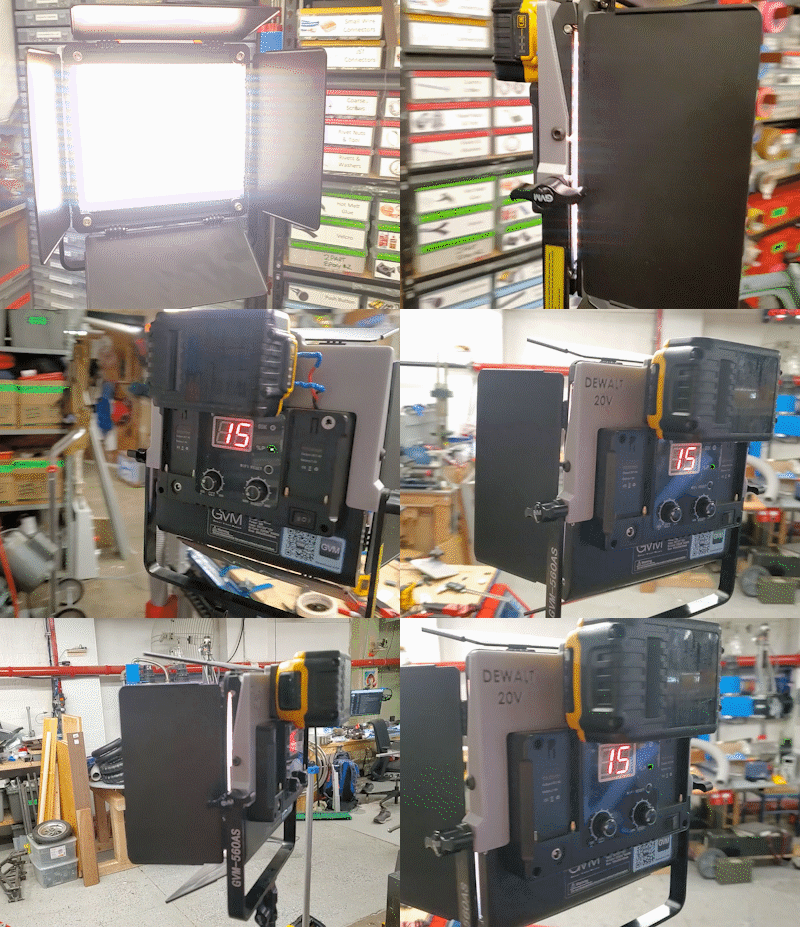
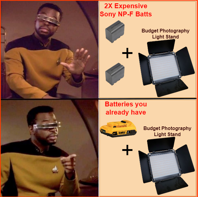
Budget video light stands upgradeI recently got two battery powered light stands from a lab clean out. They use the Sony NPF style battery packs, which are relatively available from third parties and from Sony directly. Interestingly this light stand requires two (internally in series) to run, which puts it at around ~17V of battery to run the light. I have more power tool batteries than Sony packs so let's take a look at the internals and try to adapt these lights to run from slightly higher voltage [~20V] DeWalt battery modules. |
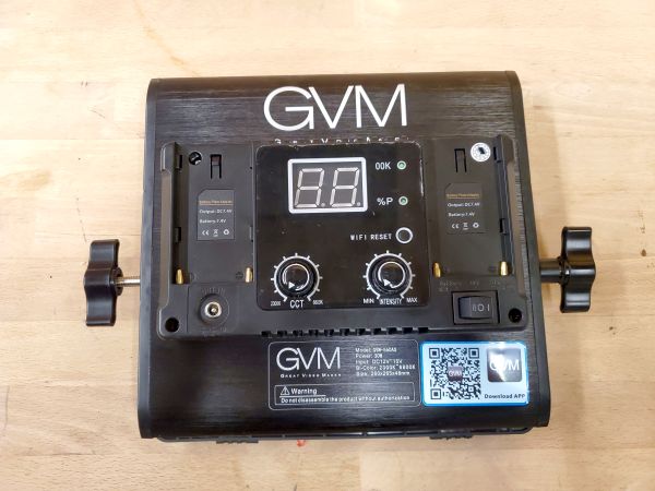
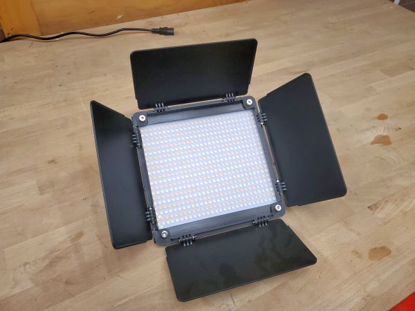
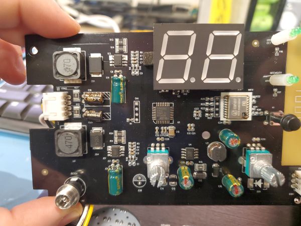
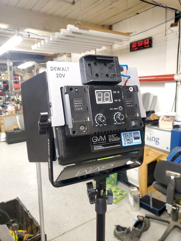
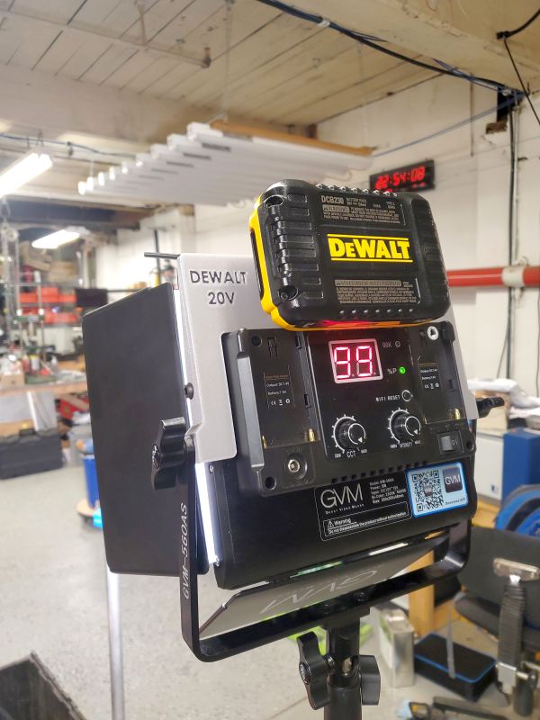
The problemThis one is pretty simple, we're all tired of supporting a seperate battery for every vendor's product ever. Noticed that most of the power tool vendors settled on 5S / 20V nominal but no vendor is compatible with another? Let's fix that by adapting this light fixture that wants sony batteries to accept ubitquous power tool batteries. If you're not a DeWalt enthusiast, the same process applies to milwakee. Taking a look at the internalsThis is a GVM Great Video Maker LED Video Lighting Kit GVM 520S-B light stand, and it looks like it is available from the usual suspects: [Amazon] [B&H Photo]. From the back you get a three position switch, separating the DC input rail from the rear battery pack supply, preventing the two from interacting. There's not any form of a latch holding the Sony batteries in place, they somewhat friction fit when installed. With the board removed from the case we get a better picture of what is going on under the hood, we get two analog potentiometers with end-stops, which feed into two constant current DC/DC converters. Why Two? this panel achieves mixed color temperature by having a ~2300K led array and a ~6800K led array. Mixing the two nets a variable color temperature. To determine if this light can run off of a DeWalt "20V" battery, let's check out the DC/DC driver ratings along with some component ratings. The constant current DC/DC chip is an XL1509 from XL Semi [Link] [Local Copy]. The chip itself supports a wide input range of up to 40V and has a built in constant current mode, which appears to be implemented internally and adjustable based on the feedback input. With the DC/DC supporting up to 40V next up was to check other components, like supplies for the logic power and DC rail capacitors for adequate overhead. Parts:To build this quick project we're going to need the following parts, along with access to a 3D printer: 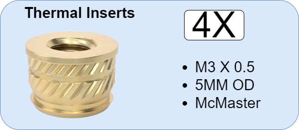
Thermal inserts used for this project available from Mcmaster-Carr [Link] 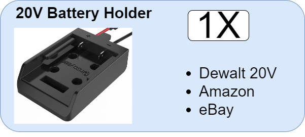
Battery holder used for this project found on Amazon [Link] 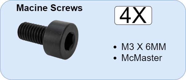
Machine screws used for this project available from Mcmaster-Carr [Link] 
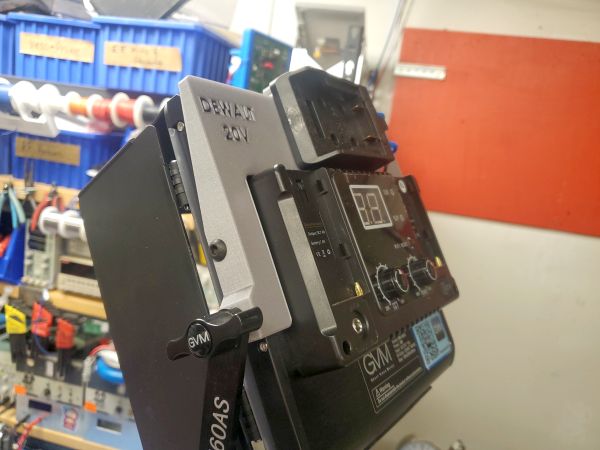
Diode for this project available from Amazon [Link] Battery Holder CAD:Now that we know these can run from DeWalt batteries, let's figure out a way to use existing mounting points to fixture the battery holder. We have a few options to work with. The goal is to also have a mount that is 3D printable on a slightly larger than normal sized build plate. While I tried to get this to fit on an ender 3, the spacing of the thumbscrew mounts defined the largest dimension. I purchased an injection molded dewalt battery adapter [Link] and started measuring and adding it to a quick mock-up model. I came up with the following, which is easy to print on an Ender 3, requires no supports or elaborate layout and can be made out of easy-to-print PLA. The file is available here: [STL] [SLDPRT] [STEP] Test FitWith the Adapter installed we can test fit to make sure everything actually fits. Without a Dewalt pack installed, the default Sony batteries still fit in place!. With the DeWalt pack installed it does block the Sony battery spots but that was somewhat intended. By picking up the threaded screw mount, along with the tripod mount we get a fairly secure holder without much effort. This also does not modify the light fixture itself. After removing the two thumbscrews and spacers the print fits right over the light stand. This is fairly excellent. The additional spacing added to the print on each side takes place of the provided spacer, but allows you to re-use the existing thumbscrew. After this I added four threaded thermal inserts that match up with the dewalt holder part. With the print fitting fairly well, next up was to add the power path that would connect from the dewalt battery holder into the light stand. An in-line diode was used to help prevent the odd case of a power supply back-feeding the connected battery pack. I used a standard 5A through hole diode, like a SB560. These are 0.40 USD, however many alternatives are available. A hole was drilled to allow the two wires to exit the shell and wrap around to the dewalt battery holder. Next up is connecting the +/- of the dewalt battery holder to the coresponding wires that enter the light fixture. Finally it's time to use those four M3 screws to attach the dewalt battery holder to the print. And like that, you now have a light stand that will happily run for hours using a much more commonly available battery format. Assembly in Detail:Concluding Remarks:
Have you noticed that there are no
advertisements or ridiculous pop ups?
|
Post your comments! |
|
Comment Box loading
|
