Dane Kouttron
This project / write up is in progress, check back for more soon!
Project Started: 12/2023
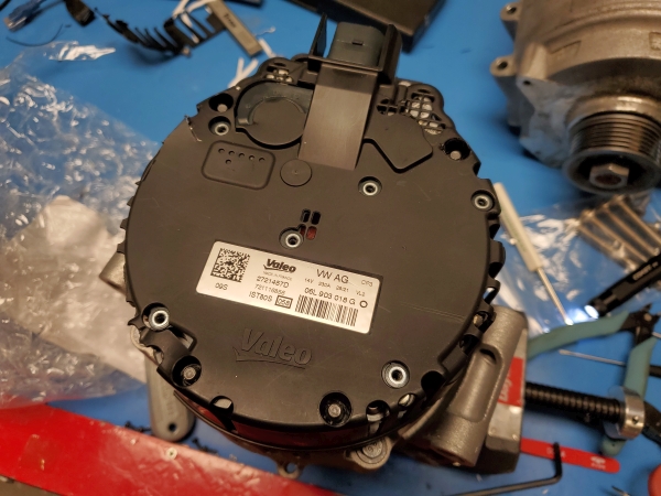
Valeo iStars Automotive Motor Generator Reverse EngineeringJust like the 48V Audi and Jeep Altermotor project, we have a new contender, a 12V Hybrid MHEV? Lets take a look and see if we can wake up this gadget. Is this the new small 12V go kart propulsion system in a box? |
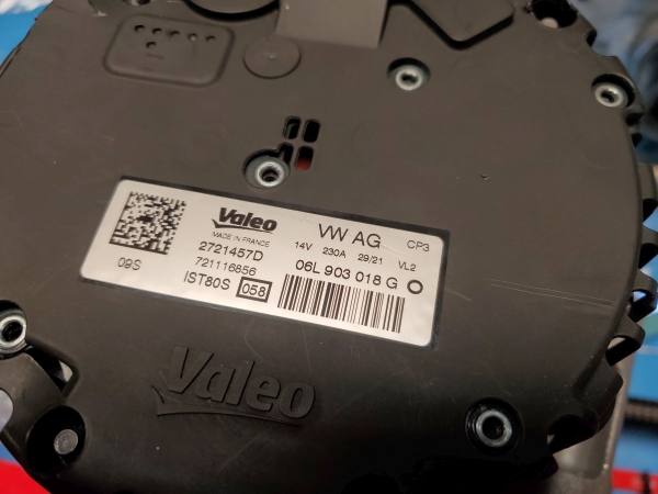
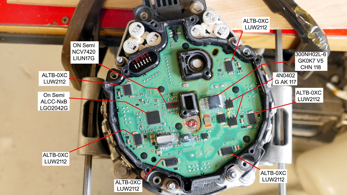
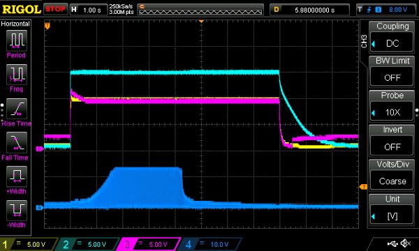
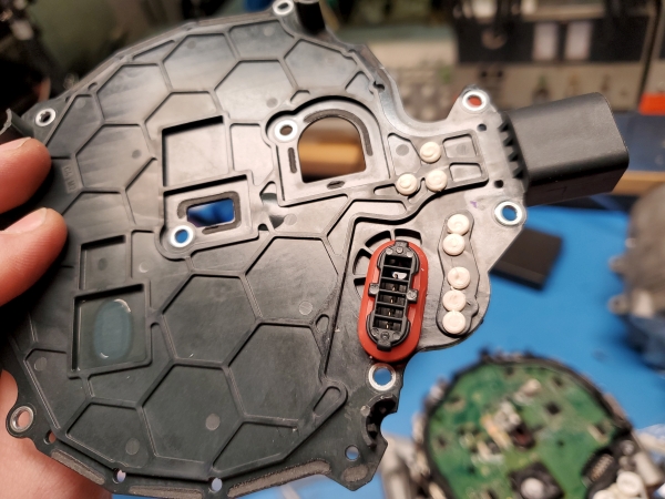
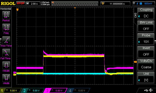
Some Project BackgroundThere are some 'low effort hybrid' vehicle typologies popping up, where the auto vendor plugs in an alternator with a built in motor controller for making technically a hybrid. Audi implemented this in a really odd way, using a 12V bus. The start-stop alternator, made by Valeo, pulls ~200A for engine start and can provide 200+A for regenerative breaking. Comically instead of locating the hybrid 12V battery pack near the hybrid motor, for some reason the hybrid pack is in the rear of the car. The hybrid pack appears to be a 4S 11AH Lithium Ion pack, part number [8W0915101A]. Either way, up front, tied to the engine is a BAS, or belt alternator starter. We learn from the short video clips hosted [here]. The goal is to use this hybrid motor as a budget automotive grade motor, while using the stock built in controller. To do so we're going to need to reverse engineer the communications protocol and learn as much as we can from observations. We learn from the quick screenshots below that the 12V alternator motor can power the propulsion system with the engine off for 10 seconds, by running the engine (I imagine) without the fuel going to the injectors. The battery is very small, at 11AH, sinking or sourcing +200 amperes is quite a lot. First step is some background, the 'test motor' we have here is from Valeo and rated for 14V at 230A, this puts us at 3.2KW for either regenerative breaking or propulsion, which is a good number to start off with. I've deemed these style automotive gadgets 'altermotors' (alternator and motor in alternator form factor). The goal is to use this altermotor in positive torque applications, commanding it over LIN or whatever language it talks and using it for small gadget propulsion, freeing it from being stuck under the hood of an engine. This altermotor is air cooled, and generally is the easiest possible way to implement a hybrid, replace an off the shelf alternator with an altermotor that can apply positive torque for engine start, while also allowing it to function as a conventional alternator. After removing the back cover we have two interesting parts, first-off the communications connector is co-molded into the back case and transfers the six pins of the connector to a vertical connector that's mounted next to the main board. We do not get to see everything as it looks like there has to be some high power hardware down below. I'm a bit hesitant to take this apart further as I only have one test motor to work from. We are somewhat in luck as this does not appear anywhere nearly as ludicrous as the Audi / Bosch 48V alter motors. We can start from here and try and learn more about whats up top. In terms of components we have some issues. Not many of these parts have datasheets : / On Semiconductor NCV7420We do have a datasheet for the NCV7420 [Datasheet Link], and it's a LIN transceiver that appears to be self powered, and contain an onboard linear regulator. Its a simple large footprint part, making it easy to probe and even solder 30 gauge wire to. This is great news. I'm more familiar with CAN which has a CANH / CANL instead LIN is one wire. We know that the transceiver's LIN input / output should basically go directly to the connector, possibly through a resistor to prevent over current on the pin, but this gives us at least one reference point on the altermotor connector. On Semiconductor ALCC-NxBI couldnt find out anything about this part, so it's likely an NDA part. A host logic connectorI'd like to find a simple connector replacement assembly and it looks like a wide band O2 Sensor has the same connector footprint. Thanks again to Andres for pointing this out, this is such an awesome option. I tried finding something similar at the local auto parts places (Autozone / Advance Auto) but alas, no real options. [Link] In the mean time I can use fairly simple jumpers to probe the onboard pins, to do this I used female crimps and just put heat shrink around the outside and slid them roughly over the male pins on the board. The first test is pretty simple, what does this alternator do without communications? You'd imagine that if there is a comms issue the vehicle should not stop being a vehicle so lets oscilloscope around and observe what this does. On the oscilloscope chart above we can observe CH1 pin 1, CH2 pin 4, CH3 pin 2 and CH4 phase volts. As i spin up the motor with an external drill motor the phase volts start building up. As soon as the phase voltage hits a threshold we see what appear to be different parts of the alternator waking up. It gets more curious as soon as we hit xxx RPM the alternator starts trying to pump power into the 12v rail connected to the motor. I observed ~100W being extracted from the drill at full rpm (2500) as measured by an electronic load kept in parallel with the battery set on CV mode. The drill process is a bit awkward, as nearly every modern drill does not like to drive an inertial load, and when the throttle is lowered generally the clutch slips, or in an impact, the impact hammer starts to get noisy. It may make sense to put together a basic DC motor + pulley to simulate drive and gather more data as to how this alter-motor operates. In the past I've used these ~1kw BLDC assemblies, driven from simple e-bike controllers. The key issue here is regen-current, nominally you either need to be running a VESC or something nice to support regenerative breaking activities, but what about a simple DC brush motor, like a CIM or scooter motor? When running from a simple switch-battery configuration with an ammeter a simple +/- 20A display should give a pretty good indication of what is going on, without being overly complex. Online Information:Lets take a step back and dig around to see if anything is publicly documented onlineWe find that there's a slide deck from Valeo with some basic information about their iStARS system, confirming that yes this motor does transmit power for aiding in start-stop, so we know that it does provide positive torque. We also get a basic inside view of the motor stack, but nothing very technical. The presentation is actually a video widget with no fast forward, you can register to view it here [link]. There seems to be a mix of the use of iStARS and StARS at this point so it would be good to get some clarity on this topic, from here [link] we find out that iStARS is an acronym for Integrated Starter Alternator Reversible System. The only actual literature on this is a 2007 presentation hosted on the Russian formula hybrid website. From this presentation we finally get some clarification, [link] a local copy is available here [link]. StARS is the older version with an external motor controller and i-StARS is the more recent version with the motor controller integrated into the motor. StARS: the old version of this altermotorI found a technical handbook that details the previous version of this system. This is StARS, not iStARS, and the biggest difference is that the alternator controller is a large external module, whereas for iStARS the module is part of the alternator assembly itself. It's possible there's some commonality in terms of communication or something we can discern from the early version: Valeo Technical Handbook in case this gets pulled down a local copy is available here [link]. It's remarkable that the same nominal power rating was condensed down to fit inside the alternator itself. This document is circa 2009, and nominally power electronics have become a lot more integrated since that time. It also appears that the motor control topology has been simplified since STARS, as we find out that this old version had a 40 pin data connector. Are you kidding me. There were two can buses on this thing. i-StARS: the new hotnessThe main page for the Valeo 12V belt alternator generator is here [link]. We do not get a lot of technical specifications, but we do find that this is an asymmetrically implemented device, with 2-3Kw of positive power output and 6-7Kw of regenerative generation. That seems very high, on a '12V' system, 6kw is 500A. On the plus side it's likely that the three phase bridge running the motor is rated for these high currents, if it is limited in positive torque to 3Kw it's not getting anywhere close to the peak rating of the silicon. We also glean '80% efficiency', which is fairly low. Thermally this alternator has a small impeller fan, at 3KW positive torque, that's 600W of thermals to get rid of, which is fairly high. Lets continue digging and find out what vehicles this is installed on, from this we may be able to discern information that vendors provide instead of the actual manufacturer. We know that the Valeo part number is 2721457D . This corresponds to an audi part number of 06L903018G . We now get a basic list from Audi Service Parts. Here's the simplified list of Audi Vehicles as of 01/2023 that use this alter-motor:
There may be other vendors who use this motor, let's see if the more European brands [Cirtoen / Peugot] have adopted these for hybrid start stop. A Mystery Youtube Video AppearsWe spy from the video embedded below a third party alternator test fixture / gadget [link]. Ok this is interesting, it even appears to be a Valeo alternator. Let's see what we can discern from this vertical video. I guess this somewhat makes sense. Conventional alternators do have removable diode packs and are fairly easy to test, resistance and diode checks are a quick multi-meter activity. These alter-motors are different, you can't really disassemble them, so someone makes a gadget for bench testing. Exciting! We find out that this is a [RTP9007S] and it is mounted on a MS-004 COM bench testing apparatus. Here's the [user manual] and the [operation manual]. We're finally getting somewhere. After some digging around it looks like this test fixture is used only for reading status and adjusting output voltage. When it's coupled to something that drives the input pulley, you can monitor the charger performance but this particular gadget does can not command the motor to provide positive torque. Adjusting output voltage is kind of interesting. I was just thinking of why this is digitally adjustable and I think this is possibly useful for not only Lead Acid batteries (14.4V charging voltage at 20C) but also for charging a 4S Lithium pack (16.4V max). This could also allow for cold temperature compensation for conventional lead acid. We find from [batt university] that at very low temperatures -25C, charging voltage for a conventional 12V starter is ~15.6V. If the car can sense outdoor temperature, or air intake temperature, it could twiddle the charge voltage to compensate. The manual of the RTP907S doesn't really have details on specific alternator pin out, but it's possible there's other gadgets with more documentation. Now that there's some prior art, let's dig up some other gadgets. I found the Autodiagger AD100+ here: [link]. This is ~460$, which is somehow on the lower end of the pricing for these gadgets. I found the user manual [link] and it does have some more interesting details, namely a pin out, specifically of i-STARS Valeo alternators. Curiously there's only 5 pins shown instead of 6 and they are in-line. Maybe this is for another iStars alternator? Lets continue digging. We find another version of this motor, a 180A variant with the part # 439845. If you squint you get the pin out, and it is also Has anyone documented alternator LIN communications?Are there any app-notes for implementing a LIN connected alternator? Take a look at the AR6000, [link], is a really weird one, it's a datasheet for implementing the alternator part of this motor , in a 5 pin TO-220 package , what the heck? This is an NXP product [link], so it's likely that there is at least some source code somewhere to demo talking to 'a digital alternator'
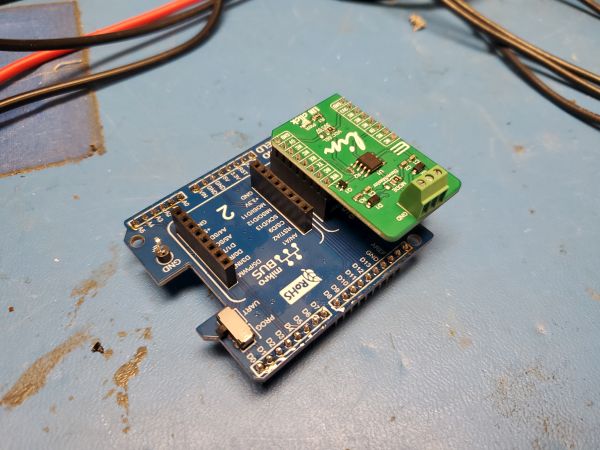
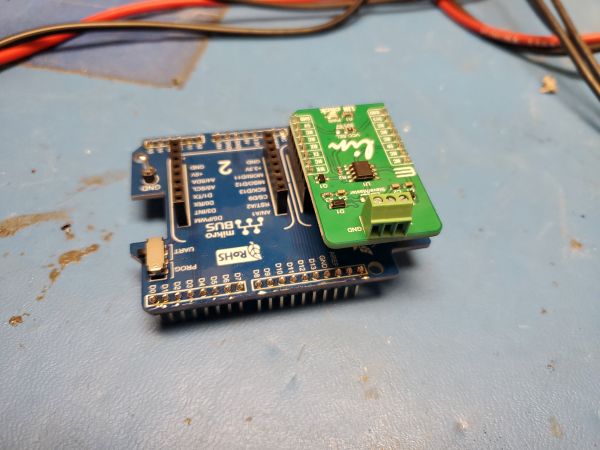
This is my first forte at talking 'LIN' so I grabbed a devkit from [Mikroe] which has a simple three wire interface for talking to a LIN bus. LIN's logic is not differential, it's actually nearly rail to rail for the battery voltage line. Paired with a devkit holder and tied to an Arduino we have a really basic LIN interface. Surprisingly the LIN module was not on amazon, fortunately DigiKey had it in stock. Links to the two parts are [Lin Module] and [Carrier Board]. To interface with the altermotor, I unfortunately had to play the trial and error game to find a connector that fit [Amazon]. It's odd but a lot of these automotive connectors are not labeled or available on Digikey / Mouser. Audi's Lin Bus guideHere's an interesting writeup from Audi [link] that we can hopefully use to help reverse engineer the LIN bus traffic. The first useful snippet we find is The sensors and actuators only react if the LIN master control unit transmits a header . We get a useful screenshot of a LIN header that would be sent from whatever the master is, and also a LIN response, as shown below. 
This does make sense, as I was observing no communications when oscilloscope probing the LIN line of the altermotor when power was applied, it's on a single wire network and its waiting for someone to commmand it to talk. We need to simulate the vehcile's LIN header and see if the gadget responds. Concluding Remarks:
Have you noticed that there are no
advertisements or ridiculous pop ups?
|
Post your comments! |
|
Comment Box loading
|
