Dane Kouttron
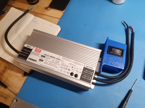
Did you know LED power supplies are fantastic at charging batteries?Battery chargers are inherently constant current power supplies with a constant voltage threshold for end of charge. Do you know what else wants constant current? Large LED highway lights. A tear-down of a recent Boston lamppost confirmed a 240W MeanWell supply hiding inside. I had been looking for a quick portable charger for snowbot, instead of schlepping battery modules up a flight of stairs and charging indoors with a balance charger and I found the HLG series of LED supplies by MeanWell. This particular LED power supply outputs within the range of one of the snowbot battery sub-modules. Integrating a watt-meter and a re-settable fuse, we get a portable 480w battery charger, in a water resistant enclosure, perfect for some budget high power battery charging. |
Some Project BackgroundI got really lucky. Normally, HLG 480 watt mean-well supplies are pricey, but for whatever reason two of these 30V HLG 480w appeared for 30$ each on eBay. Its possible the seller just had them untested as they shipped with no manufacturer packaging or they were lab surplus. Either way, when they arrived they did *work* out of the box, and I'm really interested in using them for charging duty. Here's the datasheet [link] [local copy], the part that I love is the adjustable CC-CV limits with sealed potentiometers. My snowbot packs are two 8S 100AH LiFePO4 battery modules. Their operating voltage range is 28.8v fully charged, ~20v depleted. From this info we can determine which supplies operate in this voltage region by checking the Voltage Adj Range part of the datasheet. We see that both the HLG-480H-30 or HLG-480H-36 could work. While the HLG-480H-36 minimum termination voltage would be a little high, the BMS would cut out before any charging issues occurred. We do get better charging performance out of the HLG-480H-30 as the rated current is higher (16A vs 13.3A). Some other interesting notes about this particular Meanwell supply: It accepts 220AC or even a ranged of DC input voltages. While there isn't necessarily a need to charge from 220, if I used two of these supplies on-board a snowbot it pulls in ~1kw, which can be somewhat high for a single 110VAC outlet, especially outdoor outlets. If i can find some of the 600W HLG Meanwells surplus, or the 1kw HVG models this would work really well for J1772 charging. J1772 level 1 chargers (7kw max) are fairly available, and 2kw charging would be fairly excellent (~2hr recharge). Mechanically small kw-level battery chargers are still somewhat hit and miss, especially ones that are sealed from the elements. In the ideal case I'd love 5kw of on-board charging, bringing the recharge time down to an hour. 
Two 480w chargers still result in a charge time of multiple hours, but do allow for charging from a standard extension cord. Recharge time approaches 6 hrs from the dual 480W Meanwell supply shown above. The useful operating time of the robot is ~3 hrs in heavy snow, as the impeller is ~1.5kw, with ~500w of propulsion. Given that this is a somewhat intermittent duty cycle (the impeller is not always loaded) This is not terrible, but not ideal for an industrial device. 3hrs is great for ~2-6 east coast driveways worth of activity, highly dependent on the amount and density of snow. The batteries themselves are another story. These particular LiFePO4 modules are rated for 3C charge maximum, so in an ideal world (with the batteries at a reasonable temperature) you could charge the whole robot in 20 minutes. Big Caveat here, the modules would need to be warm to charge at high rates. LiFePO4 can be damaged by hyper-low-temperature charging. Making off-board chargers out of LED Power SuppliesSo the plot is to use these as off-board chargers, or something that lives outside of the snow robot. In this case they are portable and fit easily in a backpack. While these technically 'just work' by applying mains and connecting to a battery directly, I also have no idea what they are doing during that time. Gadgets with no local display indicating how they aren't fabulous, even budget scooter chargers have *some* indicator light. Lets plot some system requirements and convert these LED supplies into battery chargers with status indication. Ideally We solve the following
Charge Current IndicationThere's plenty of panel meters that 'just display voltage', ranging from 'actually waterproof' to incredibly budget friendly. As this is an outdoors-ish device, some moisture tolerance would be great. Here's where i stumbled on a really neat little gadget. 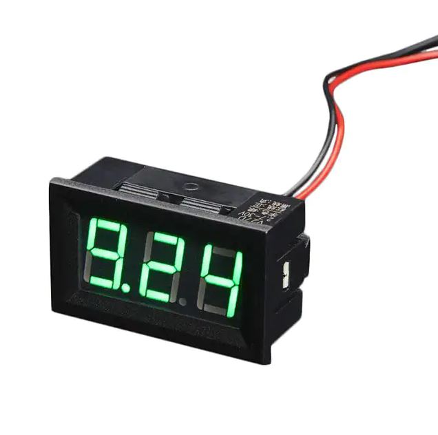
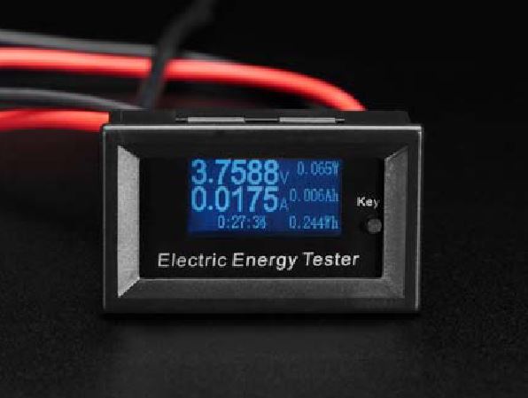
Adafruit re-sells what I can only refer to as 'an adorable little wattmeter' [link]. For ~22 USD, you get a tiny display that can measure up to 20A at up to 150V (which i would find somewhat dubious). For 30V at 16A, we're well within the limits of this 'electric energy tester'. On eBay they show up as "7 In 1 Electrical Parameter Meter Power Voltage Current Time Energy Tester" for ~16 USD. Lets grab one from Adafruit and see if it fits the bill. 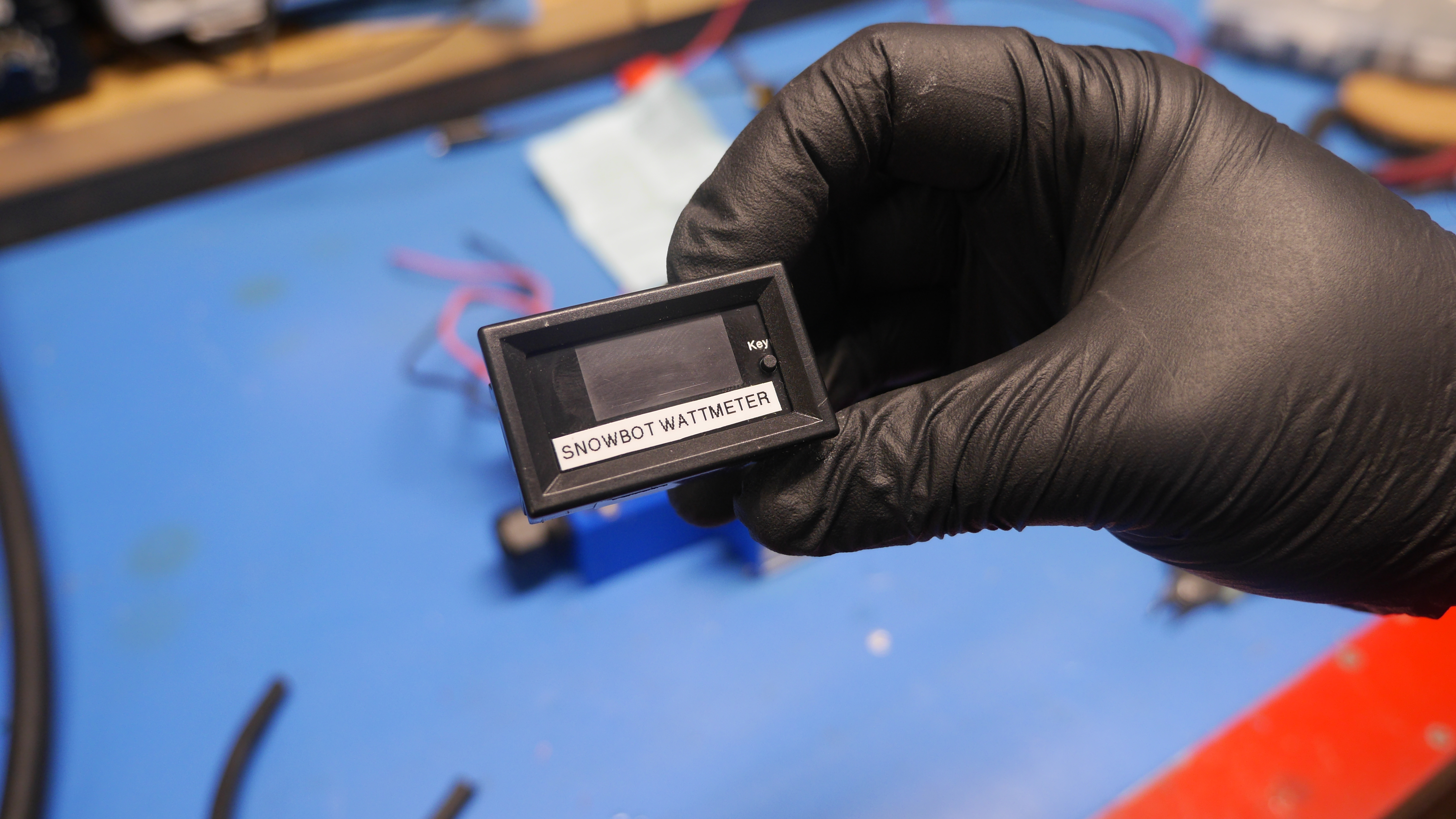
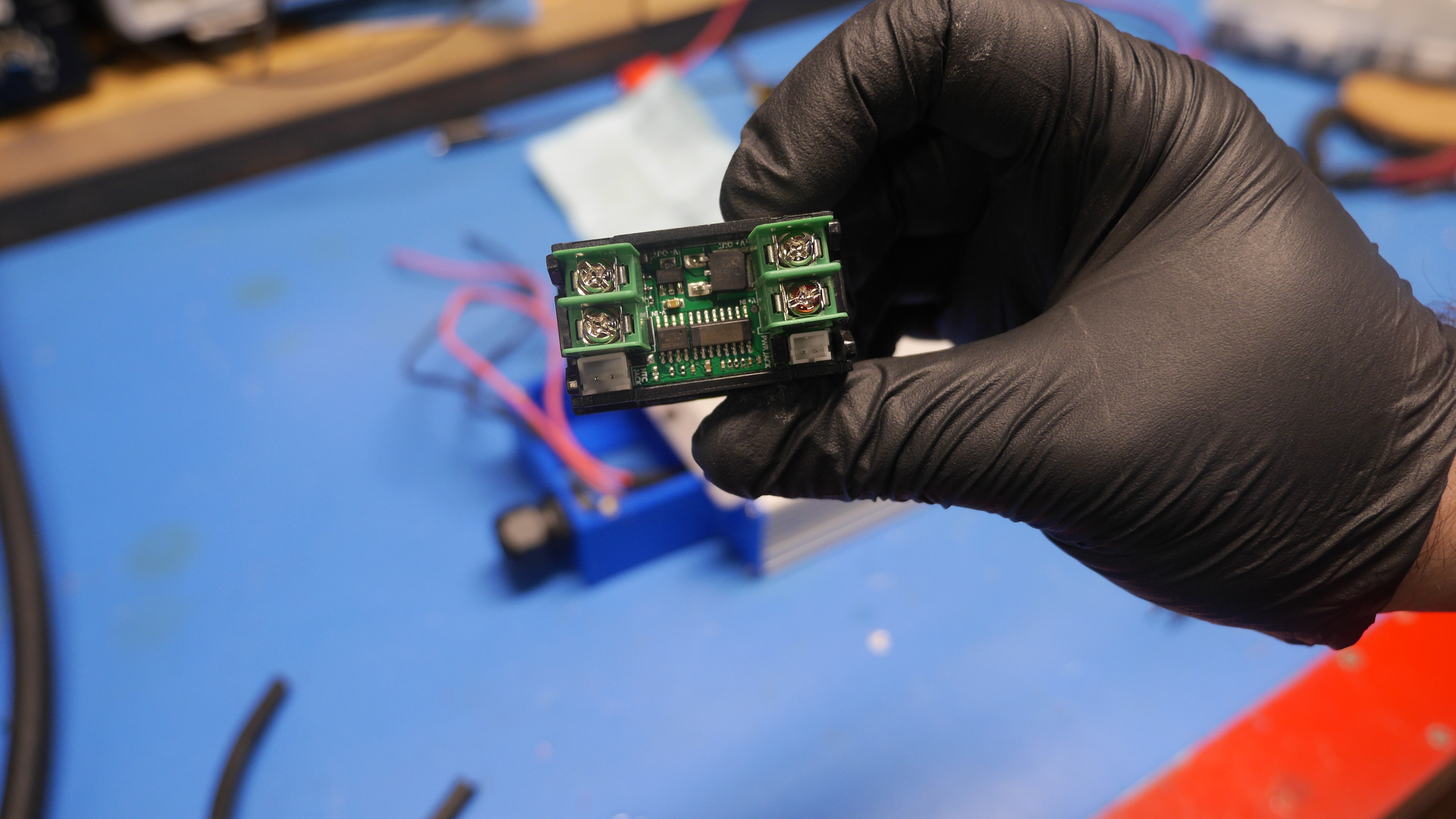
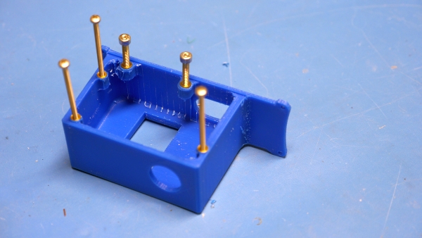
Yep, it is adorable. After adding an appropriate label, we're good 2 go. I fired this up with a bench supply and its pretty excellent. It does have a pushbutton on the front which cycles thru a few menu settings, fortunately it appears to keep track of which menu setting you were in on the last power cycle. This is not waterproof but it could be made to be a bit more waterproof. conformal coating the control electronics would be a good first step. Next up is plotting a way to mount this to the meanwell HLG supply without it becoming too goofy-large. This is what I came up with, an add-on display that doesnt significantly change the footprint and also provides cable strain relief for the charger. 
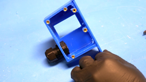
With the CAD design complete, lets print and see how well everything fits. The cable gland itself is kind of large and I was somewhat concerned the nut would not seat well against the wall, but with a little bit of edge cleanup it fit really well. After a quick fit test, I installed thermal inserts. I love brass thermal inserts. To install these i just heated an insert while it was fully threaded onto a screw, pressed it in manually using that screw and then removed the screw after it had cooled. This works remarkably well for simple parts, where high precision is not required. 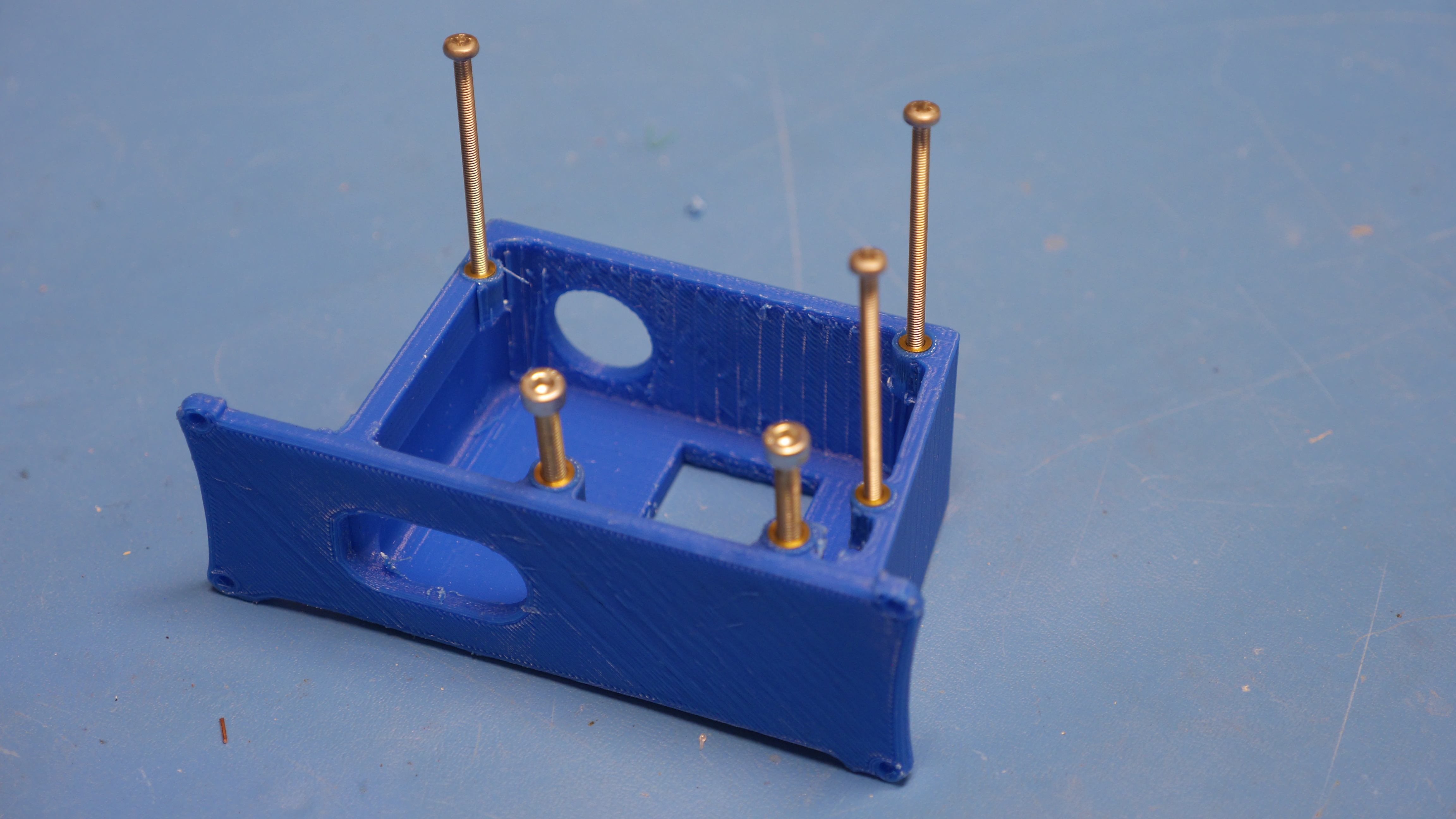

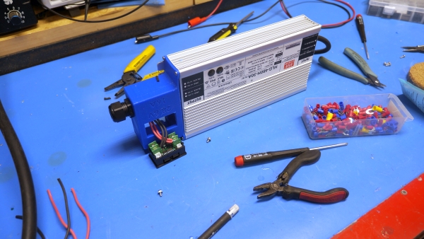
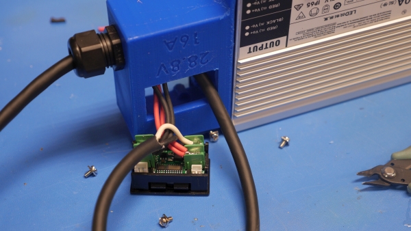
The next part was determining if it lined up with the meanwell case. While i did leave some extra space on the printed mounting holes, its always somewhat curious to see how things turn out for allignment. Note that the large hole on the side allows the power supplies grommets to clear. I'm not removing the side of the supply, there's no reason to, but I am using its mounting screws to hold this in place. Speaking of screws, the case screws are self-tapping plastite-ish. They self thread into the aluminum extrusion and hold the sides of the supply together. Interestingly the supply internals are *all potted* like this thing is a solid block inside. The potentiometers are acccessable via tubes that go between the supply and the top case but otherwise everything is gray epoxy. It fits surprisingly well for a first go. There's a little bit of warp to the print, but otherwise this is looking great. I initially planned on re-using the self tapping screws that were already installed, but with the added length of the print and the fact that the extrusion has a lot of available screw depth to screw into i opted for #6 stainless self tapping screws that were 1/2" longer than the stock ones. With the print installed, its time for the 'dont screw this up' stripping back of the long wires installed on the power supply. Both of these wires are connected in parallel, but the stripping back of the outer insulation was a little tenuous. I sliced the outer insulation very very lightly to give the wire stripping a chance to work. Somehow this worked and I didn't nick the wire insulation. Incredibly surprised as I was banking on having to re-heat-shrink the wires. With everything stripped back I trimmed both the red and black outputs from the MeanWell and soldered directly to the screw terminals on the back of the power meter. The screw holders were remarkably small, like, not even close to being a standard ring terminal size, small. Soldering also prevented the issue of screws coming loose and causing issues. 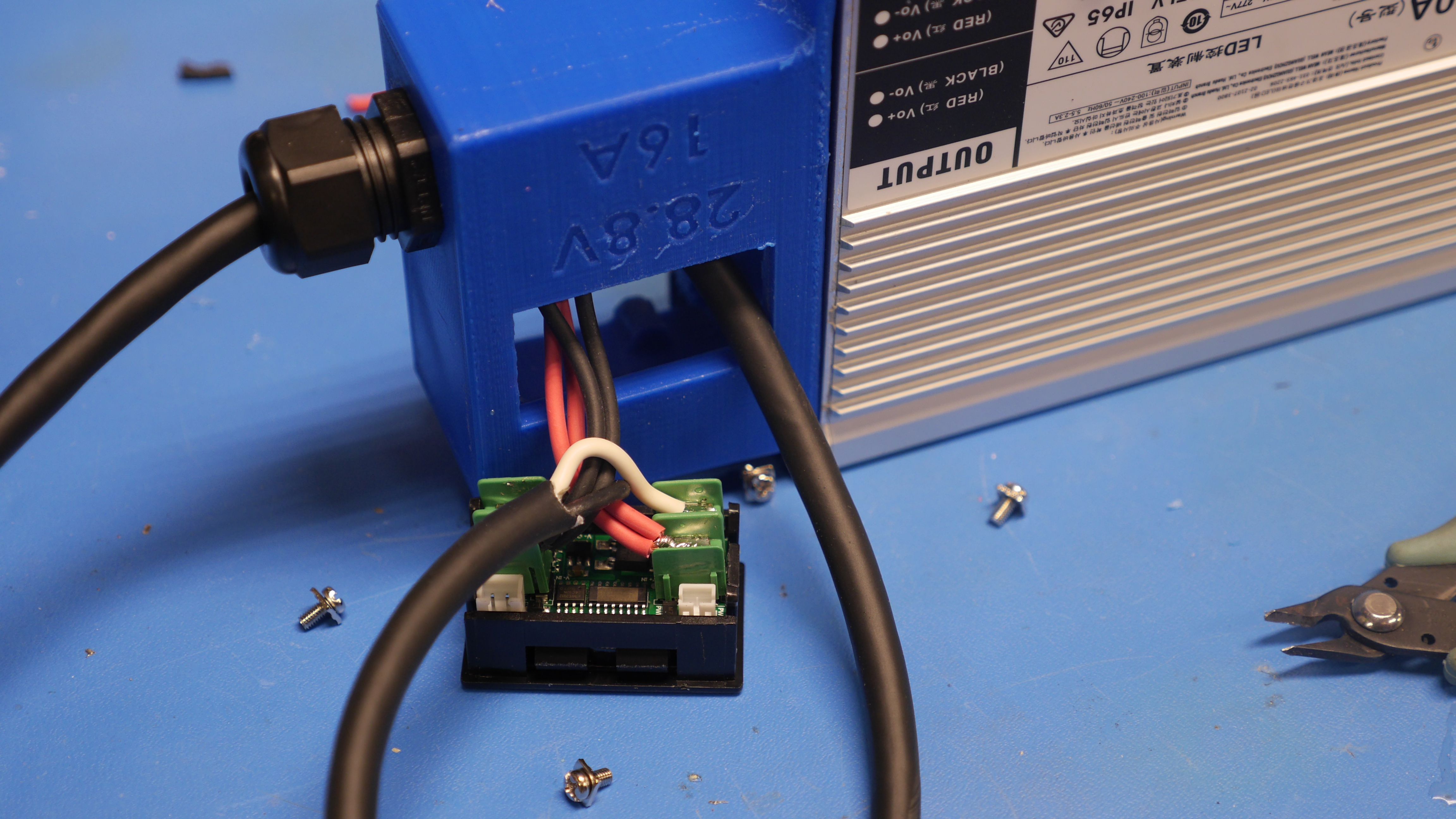
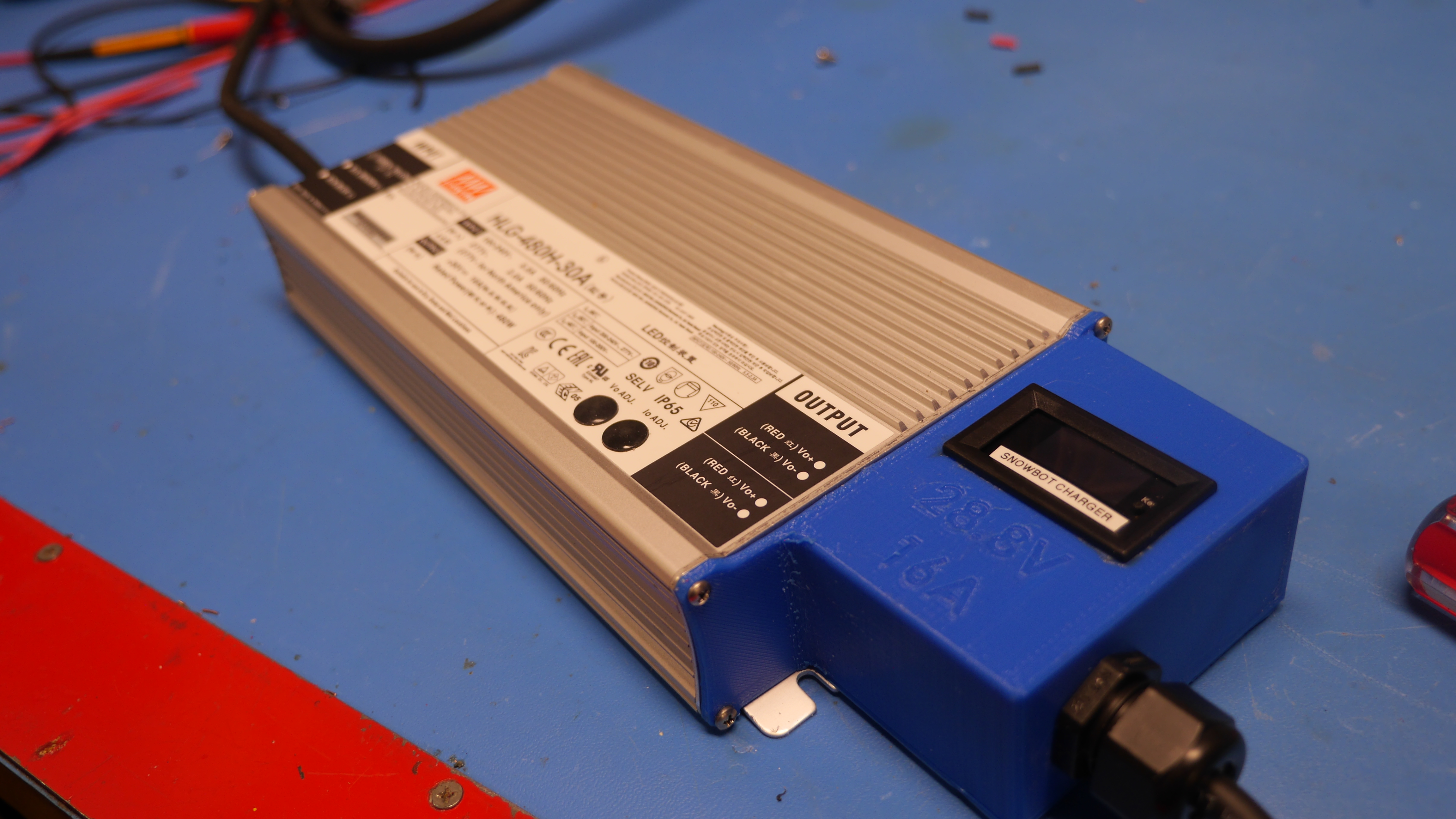
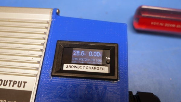
And the last bit is to snap everything together. I had test fit that the panel meter cleared the print so with the output cable installed and fed through the cable gland that's acting as a strain relief all that was left was to fit everything in and package it up. I think i checked that the panel meter was going in the correct orientation at least three times. For extra rigidity, the print picks up two screws from the flange bracket, with the back cover printed and installed the screws go through the back plate, through the cover and into the printed enclosure. These made a huge difference in the rigidity of the printed enclosure as now its constrained not only by one large face but also an angle mount. I did leave space available to pickup the other remaining open slot in case I wanted to hard mount these at a later date. VisibilityWith everything assembled this ended up coming together really quickly and looking fairly excellent. This is not going to be 'sunlight readable' but it is plenty visible in an overcast environment. I placed a zip tie around the cable inside of the cable gland mate and it really keeps the cable strain relieved. Very happy with how this came out. I think a thin plastic cover on top of the display would work well for keeping moisture out but would also likely make the display harder to read in outside conditions. Holding the charger by the charger cable seems to work even though its not terribly advisable. 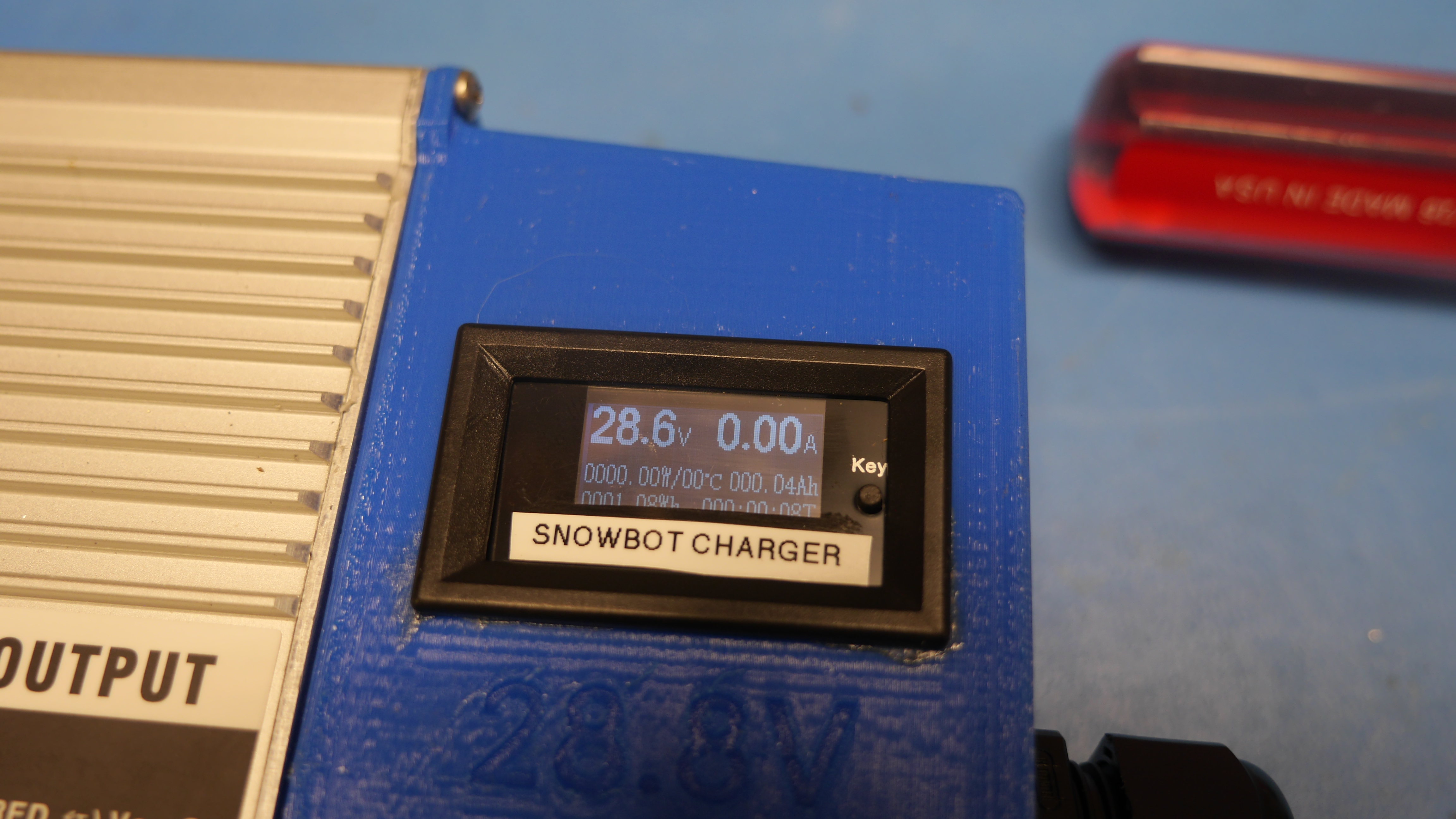
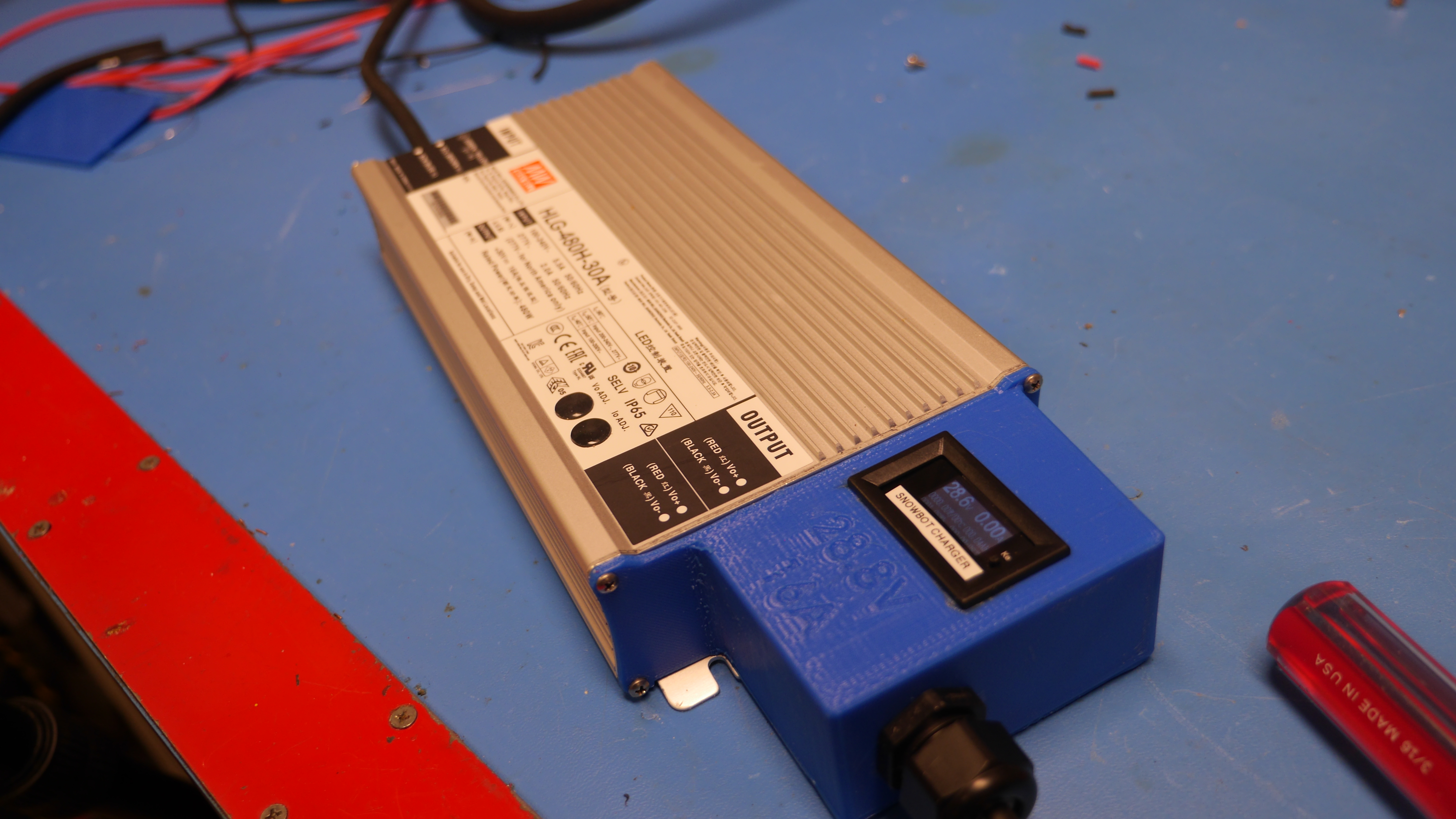
It came out fairly reasonable, I need to do the spray-paint coloring trick to fill in the voltage/current label so the actual rating 'pops out' more. It would be great if the display was like 50% brighter, as it is its somewhat dim but the price and size are right. CAD FilesThere's only a few parts to this assembly, the enclosure and back cover. The thermal inserts and screws are included in the solidworks assembly. For the prints I used dremel 1.75mm blue PLA with a high infill. The cable gland used is this model [mc-master] Concluding Remarks:
Have you noticed that there are no advertisements or ridiculous pop ups?
Want More?
|