
Dane Kouttron
Project Started: 11/2020
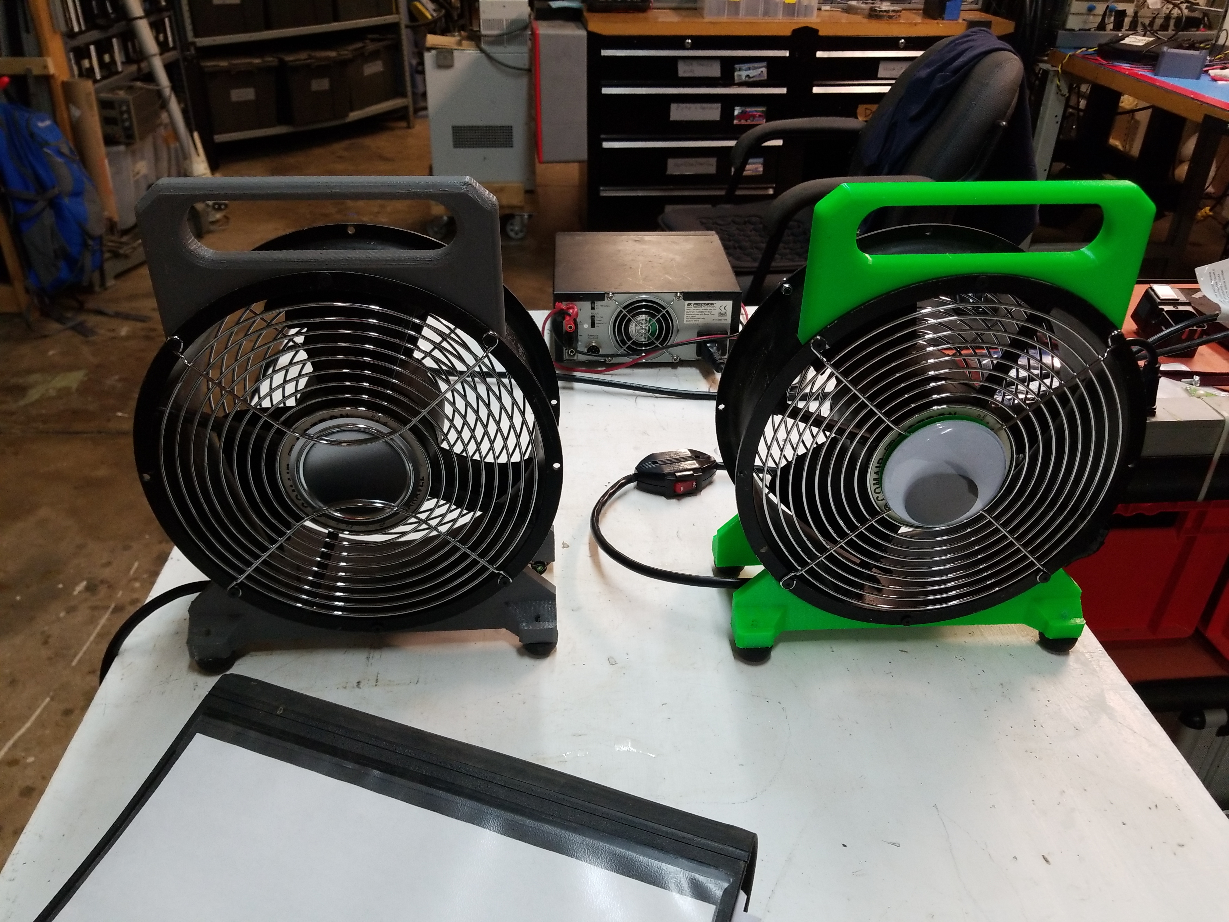
What if Mike Wazowski was a 10" fan?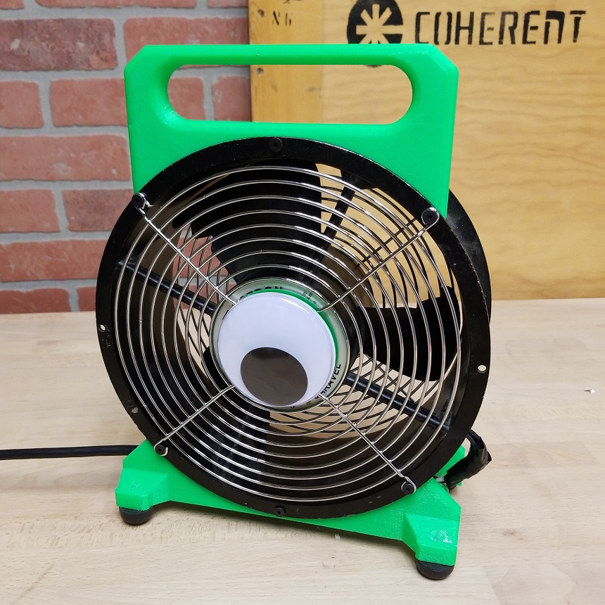
OK, joking aside these 10" diameter fans are everywhere in the industrial surplus realm.
|
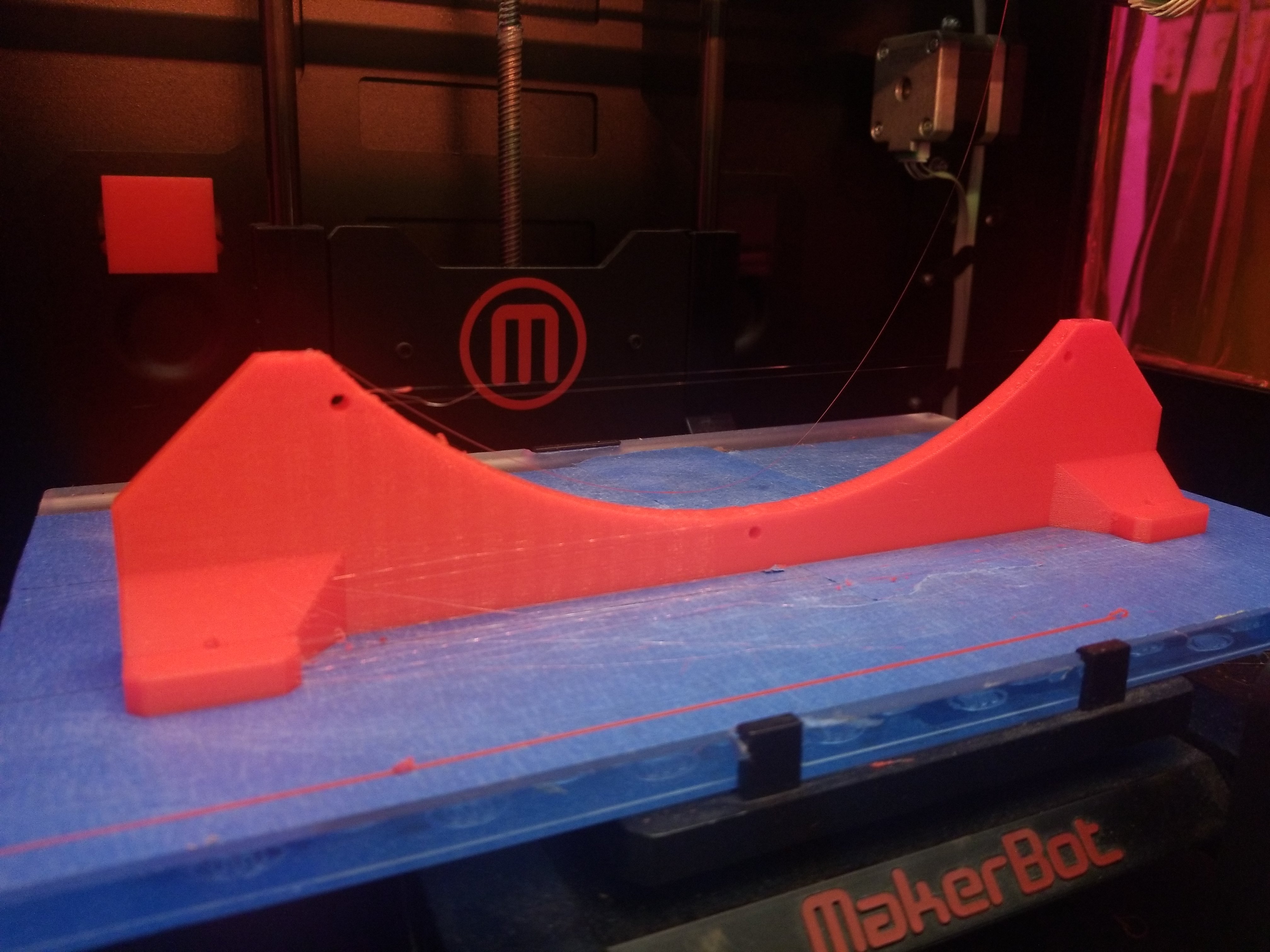
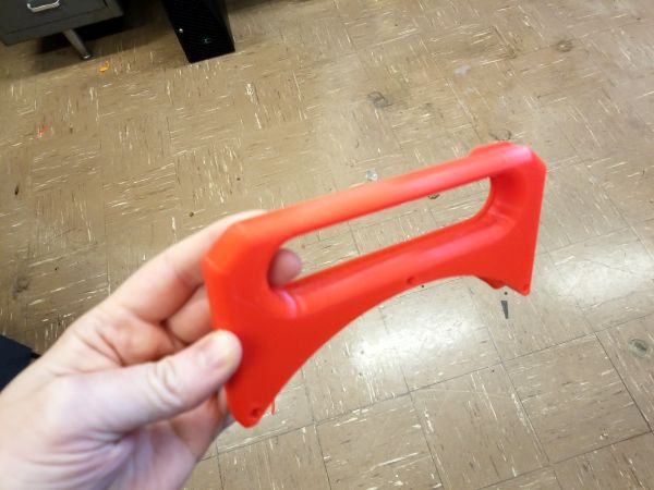
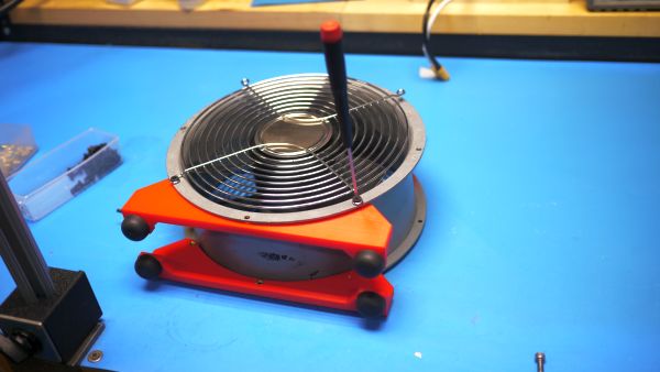
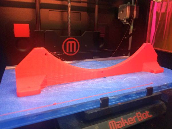
What are you up to?The goal is to make these fans safe and quiet to use, while also relying on cheap printed parts to form a simple base and handle. No drilling or milling is needed here as the fan itself has fairly standardized mounting points and using budget grade printers. All the parts for this build can be fabricated on an ancient makerbot replicator. The largest part, the base, fits well within this footprint. Infill is only somewhat important for the base, I opted for 30% with 3 external perimeters (shells). Each base took a little under 2 hours to print out of PLA. With some quick SolidWorks-ing I came up with this model. The model below is interactive, so you can spin it about to change the view / perspective. With the model complete, let's start printing. It's mid-pandemic and where I'm presently cooped up there's an old replicator 2 available. At this point a rep-2 is a decade old, but it still works. One of the benefits of this CAD model is that it fits on even this basic printer. While the model is green above, I opted to make one with the filament i had on hand which was some dremel red PLA. 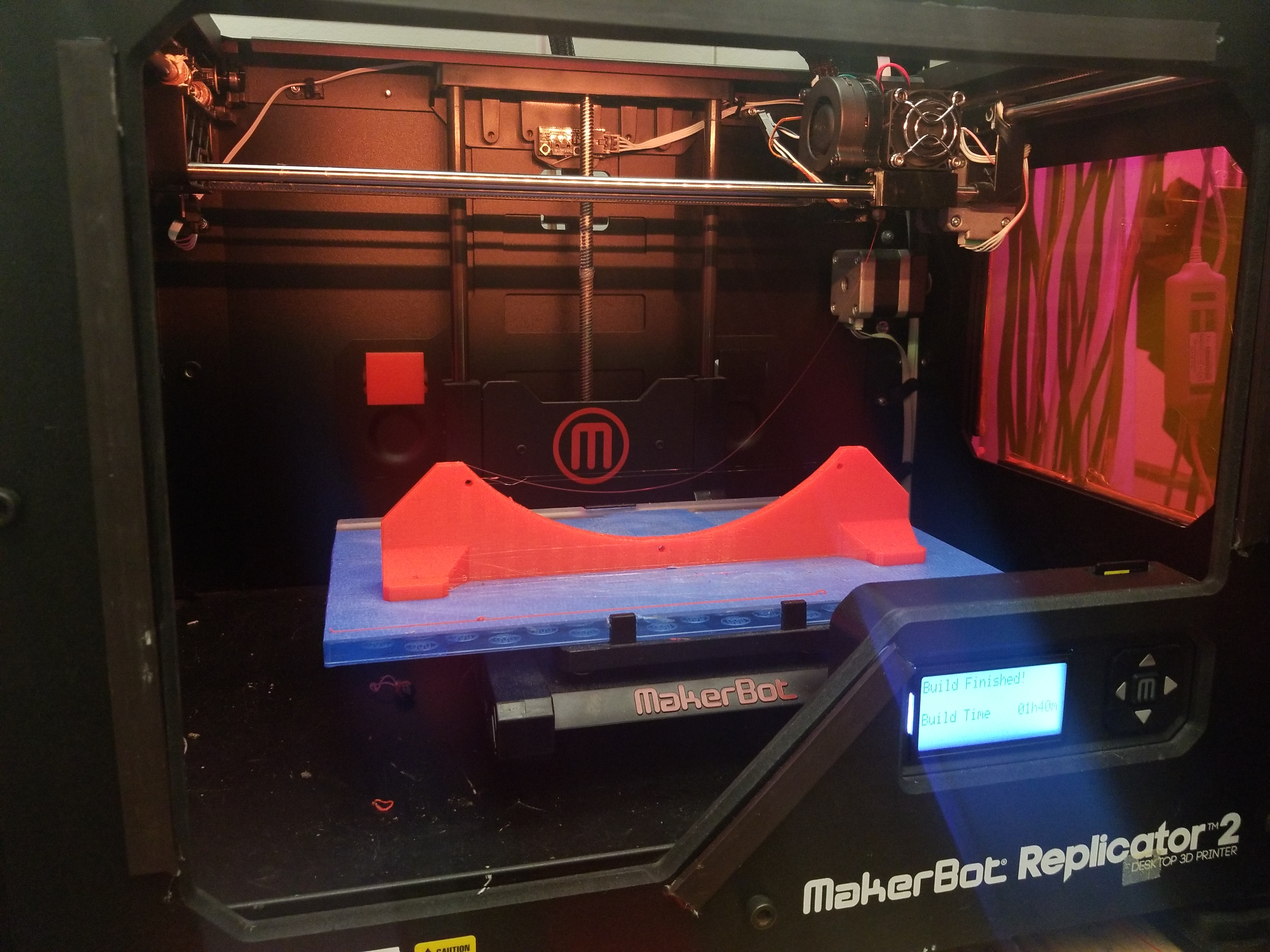
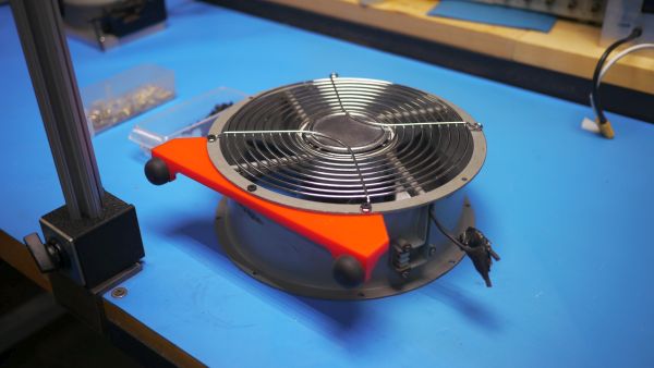
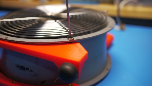
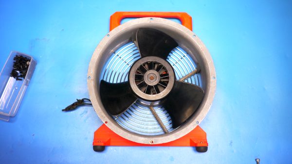
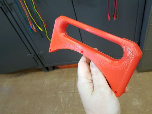
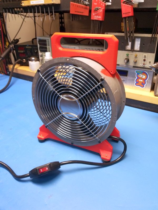
With the parts printed, lets start assembling the bottom. Note that during this build, I made a lot of these so the color of parts may vary on each build snippet. A majority of these photos were also taken in early 2020, and white balancing was clearly missing. It's really remarkable how standardized these fans are, everything 'just fits' between a variety of fans. The design of the feet also holds the fan grill in place, to minimize the number of screws. Three M4 x 12 mm Flathead screws are used on the base and thread into the thermal inserts we installed earlier. Because the thermal inserts are through hole, if you don't have the exact size you can use longer. 10mm-15mm works fine. The second base installs similarly on the backside, holding in the rear fan grill. Next up we install the handle on the top in a similar fashion. Note that at the point of writing i had not yet discovered how much better a reflow hot air source worked instead of a direct soldering iron for heating up thermal inserts. Both work fine, but the soldering iron approach on the perimeter does leave leftover solder which sometimes gets in the way. With the thermal inserts installed the same M4 flat head screws were used to hold the handle in place. One of the advantages of flathead screws here is they provide a wedged surface to clamp the fan grill in place, this somewhat prevents the grill from rattling. With the feet attached it was time to see how it looked. Comically it was not as stable as it looked in the solid works model. I was surprised that I missed this, the tipover angle is ~10 degrees, and given that the fan will provide *some* nominal force when its on, this will likely tip over fairly easily. Time for some model updates! I did not particularly like how the rubber feet brass thread poked through the holes on the bottom, so changing around the base model seemed like a pretty good plan. How much *force* could a 10" 'serverfan' actually produce? We can find out the pressure and CFM from datasheets and make a quick comparison. Interestingly there's also 24V variants of these fans, so its very possible to 'make' a 20v DeWalt battery plug-in variant, for extreme portability. I stared at this for a bit and instead of re-designing the parts, I tried flipping them around to see how much the stability would have changed. This worked fairly well, I opted to slightly increase the length of the feet on the print for the final version but it passes the quick pushover test without having to really change much. With the feet flipped around, it's time to wire up the fan. There's a really well made mains cable assembly with a built in switch available on digikey [Link]. The small rubberized cable glad provides a bit of retention for the cable but otherwise the mains wiring is farily easy. I used a small ring terminal to attach the fan shround ground to the green cable ground. The existing threaded parts of the recycled fan were fairly stuck in place self-tapping style hex screws that were fairly corroded. Despite best efforts they were somehow impossible to remove. With the existing screws unremoveable, I ended up grounding off the heads of the screws and then adding a new location for a grounding screw. In this case I drilled out a tap hole for an M3 screw, tapped the hole and added a tiny M3 socket head cap screw. Realistically this could have been a 6-32 or even a 4-40 so long as the ring terminal matched up. With a solid ground connection to the case we're just about done with this lil assembly. I ended up making a few of these to combat summer heat using these surplus fans. So far there's a green, a red and a gray. I did end up giving away the red one to family and found that the infill for the handle should go up from 30% to something like 60%, as they are effecient at dropping things. All things considered though they survived family, which should have its own IP rating. Clearly there should be an IP-54 F for surviving family use. 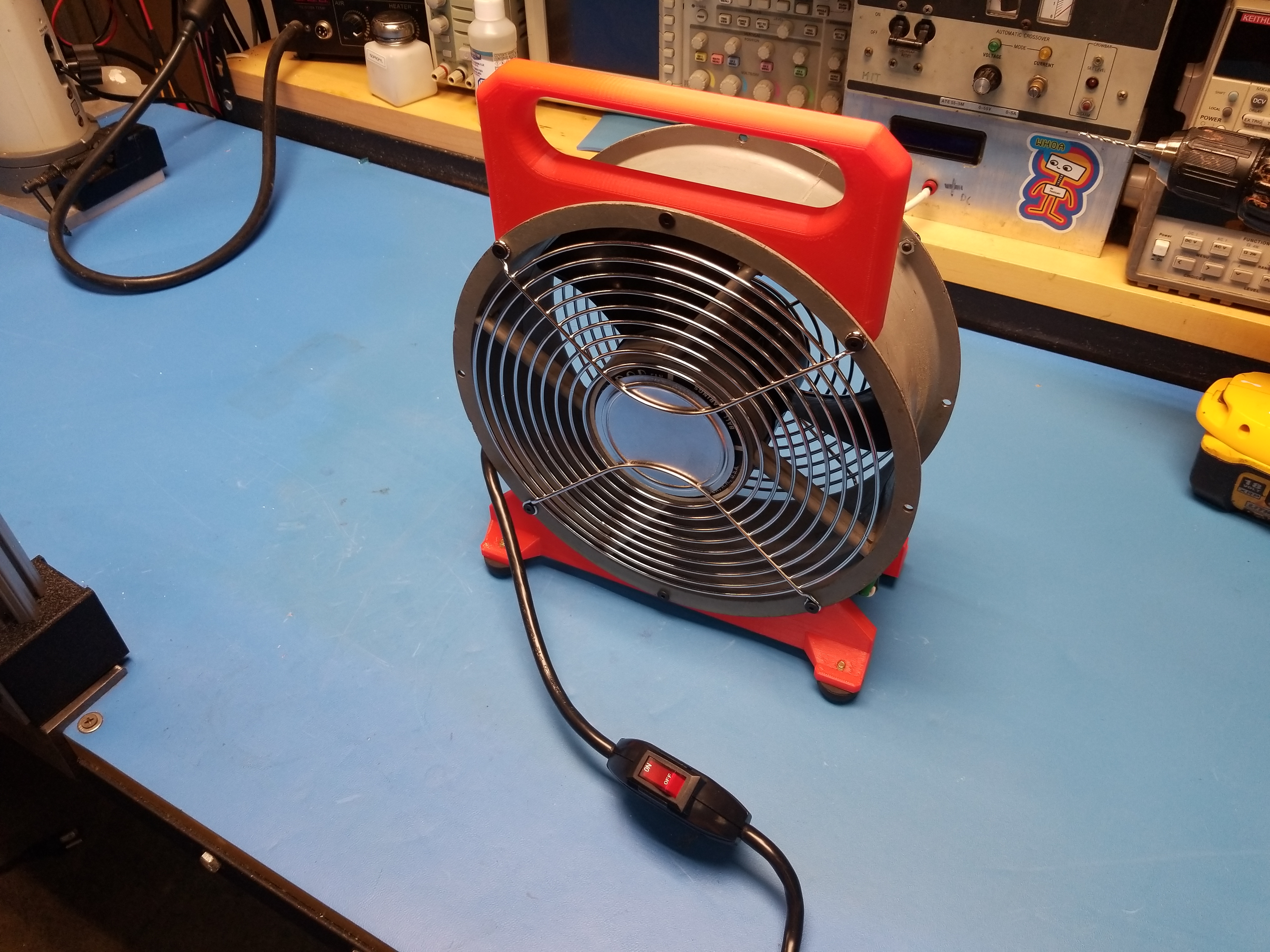
CAD and 3D Printing Files3D Printed CAD Files
Base STL [Link]
Handle STL [Link] Solidworks Assembly [2017] [Zip Archive] Mechanical hardwareThermal insert for rubber feet [10-24 size] [Link] Thermal insert for base prints [M3 size] [Link] Flat head screw [M3 x 12MM] [Link] Nylock Nut [M3] [Link] Rubberized Foot [10-24] [Link] Electircal hardwarePower cable with switch [Link] |
Have you noticed that there are no advertisements or ridiculous pop ups?
No cookie banner or newsletter?
I'm trying to make a better web, feel free to support it.
Want More?
Here's a behind the scenes look at my work space and some of the images that did not make the cut to be included in the write-up:
If you have questions or comments, ask below or send an email
Post your comments! |
|
Comment Box loading
|