
Dane Kouttron
This project / write up is in progress, check back for more soon!
Project Documentation: 08/2026
A mostly-printed pneumatic blast gate for dust collection
Tools make dust, dust extraction systems help keep that dust down, however its better to allocate that dust extratcion to only the tool in use. I evaluated a few off the shelf options but ended up going down the DIY route. Associated files and fabrication details are available below. Follow along on the adventure of getting everything together and learning to VLA |
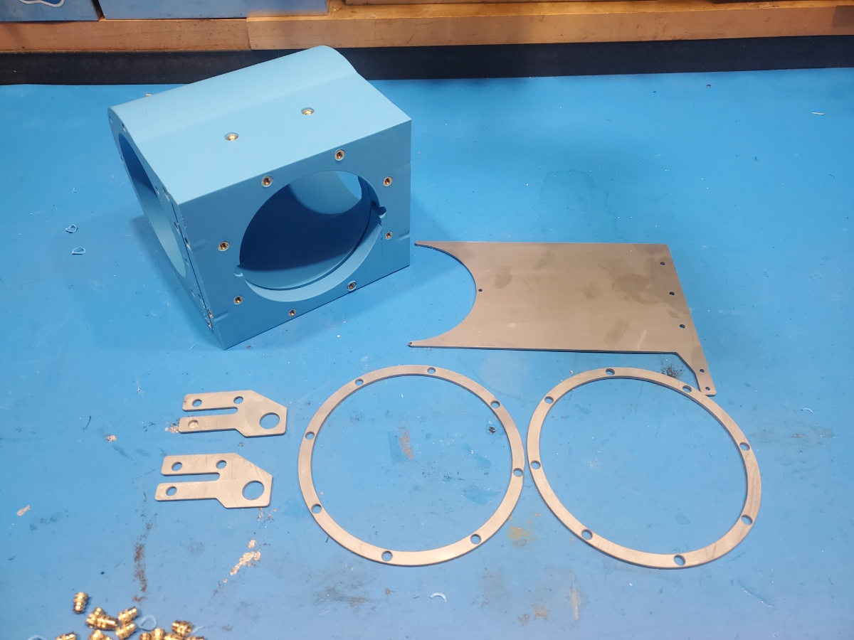
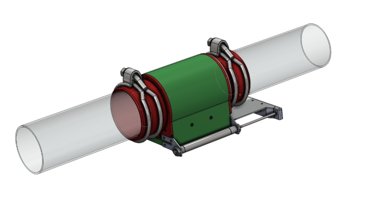
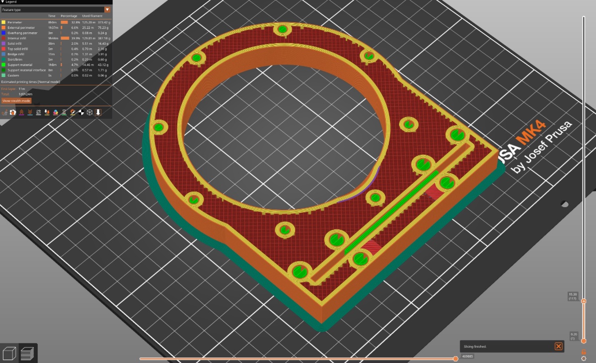
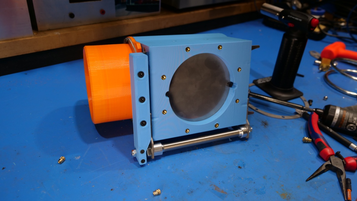
Blast Gates?Here is the basic idea, a few printed parts, all of which fit on normal consumer grade printers, that bolt together to allow a configurable, flexible remote-actuated dust collection blast gate, for a fairly low price. For dust collection I really like to take advantage of clear acrylic tubing. As of recent,a six foot long, 4" outer diameter PVC piping is around 75 USD, while a clear acrylic version is roughgly 10$ more. The clear acrylic is not pressure rated, but we're not using it for pressure, we're running vacuum. Using clear acrylic line does give you an advantage, you can see where blockages exist, or associated buildups of sawdust are hiding, something that's not apparent with opaque PVC. Unfortunatley acrylic is significantly less abuse tolerant, so instead of hard PVC fittings we're going to use squishy TPU printed mates to both let the system compensate for tolerance betwen lines and also to not stress the lines as is. Electrical actuation is always an option, but relativley small pistons are wildly cheap, especially surplus. having the ability to push 60lbf with such a tiny part, fed from tiny 5/32 air lines is amazing. Getting similar electrical performance is possible but would require some significant gearing & mechanical advantage. This is not all 3d printed I did end up using a few sheet steel parts, however they can be substitued for 2.5mm acrylic / acetal lasercut sheet parts. The loading is relativley low. I opted for 0.090" stainless steel just for asthetics, it does look amazing, but is completley unnecessary. There are a lot of thermal inserts in this design, possibly too many. I did want the option to swap different mating surfaces, either to drop the 4" vacuum line down to a smaller diameter, or to have an offset-angle TPU part for the odd tubing runs. As a result of this approach the center blast-gate module is the same assembly, with different, configurable end options. Design InspirationThis started with a manual blast gate design I've been using on small shop tools. I've put these to work for over 4 years and they've survived a lot of abuse. Concerns, like the acrylic getting frosted by chip cleanup, or the printed parts loosing a seal over time were put to rest. I went for a manual route as the actual suction line was mechanically (intentionally) reachable. Now with an overhead vacuum main, for larger tools remote actuation is the way to go. Here's those manual, 5 year old printed gates in action below. Note that, instead of being part of a pipe-to-pipe joint, these require holesaw drilling a 3" diameter cut into the 4" main line, something that's not difficult but doesnt scale well if the hole size approaches the size of the main line. A Very Large PrintA whole spool of reasonable PLA filament is presently ~20 USD, locally at microcenter, physically in a city environment. Thats remarkably reasonable, coming in at roughly 1.3 burrittos in equivalent currency. TPU is slightly more expensive, but also reasonable. My initial constraints are to ensure all of the PLA parts fit within that 1kg limit, with adequate margin, including supports Lets look at the printing settings, I opted for a high wall count to help add material around the sliding blast gate and also provide ample material for thermal inserts to bind to. Overall there's a 50% infill for the remaining space, and given the size of this part that's fairly significant. Full supports were chosen to keep the tool-facing orface reasonable, given the overhang, but most importantly the slot for the blast gate was printer vetrically, this ensures no infill necessary on this part. A brim was selected to increase build plate adhesion area. 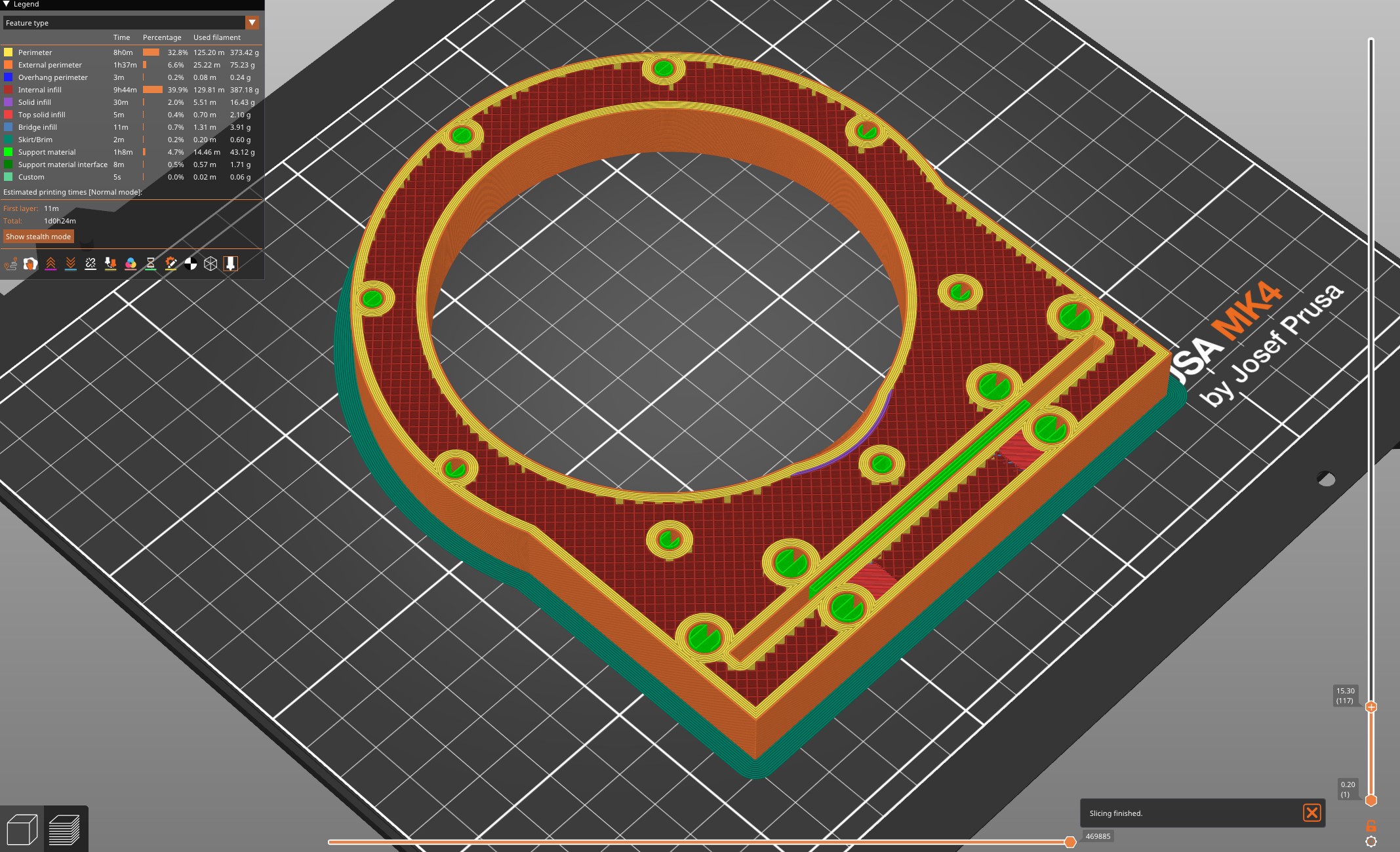
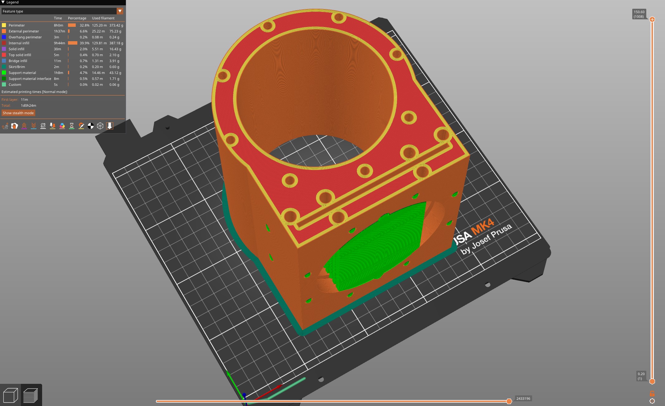
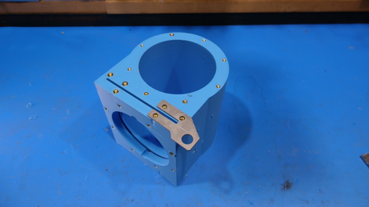
Print time on a Prusa MK4 / Creality K1 is around 20 hours at a conservative print profile, which is sizeable. With the above settings the main part comes in at roughly 900 grams, with an additional 60 grams for the printed handle that interfaces with the piston. Both fit eaisly on a normal commercial printer volume. The flexible TPU prints are also fairly large, providing a lot of contact area with the mating 4" tubes. I've found that elderly direct drive 3d printers excell at printing TPU. Shown below is a Type A Machines Series 1 printer, a really wonderful printer from ages ago. It really excells at large TPU prints, as shown from A sprinkling of thermal insertsI opted for M4 and M5 sized thermal inserts, however in retrospect it would have been a bit simpler to have only used M4. The M5 inserts were specifically for the piston bracket attachment points and realistically were overkill. The TPU port attachment points are all M4. 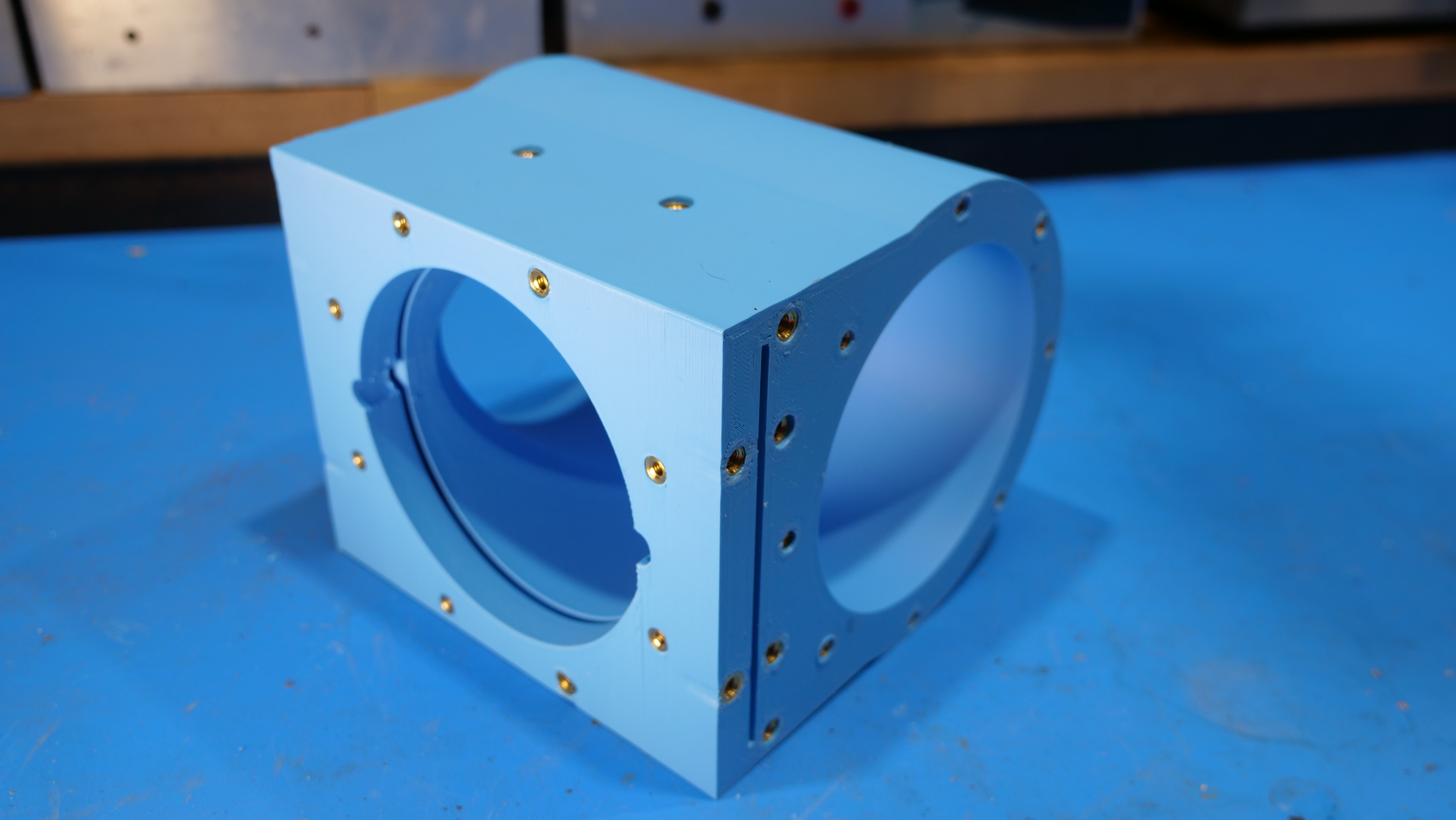
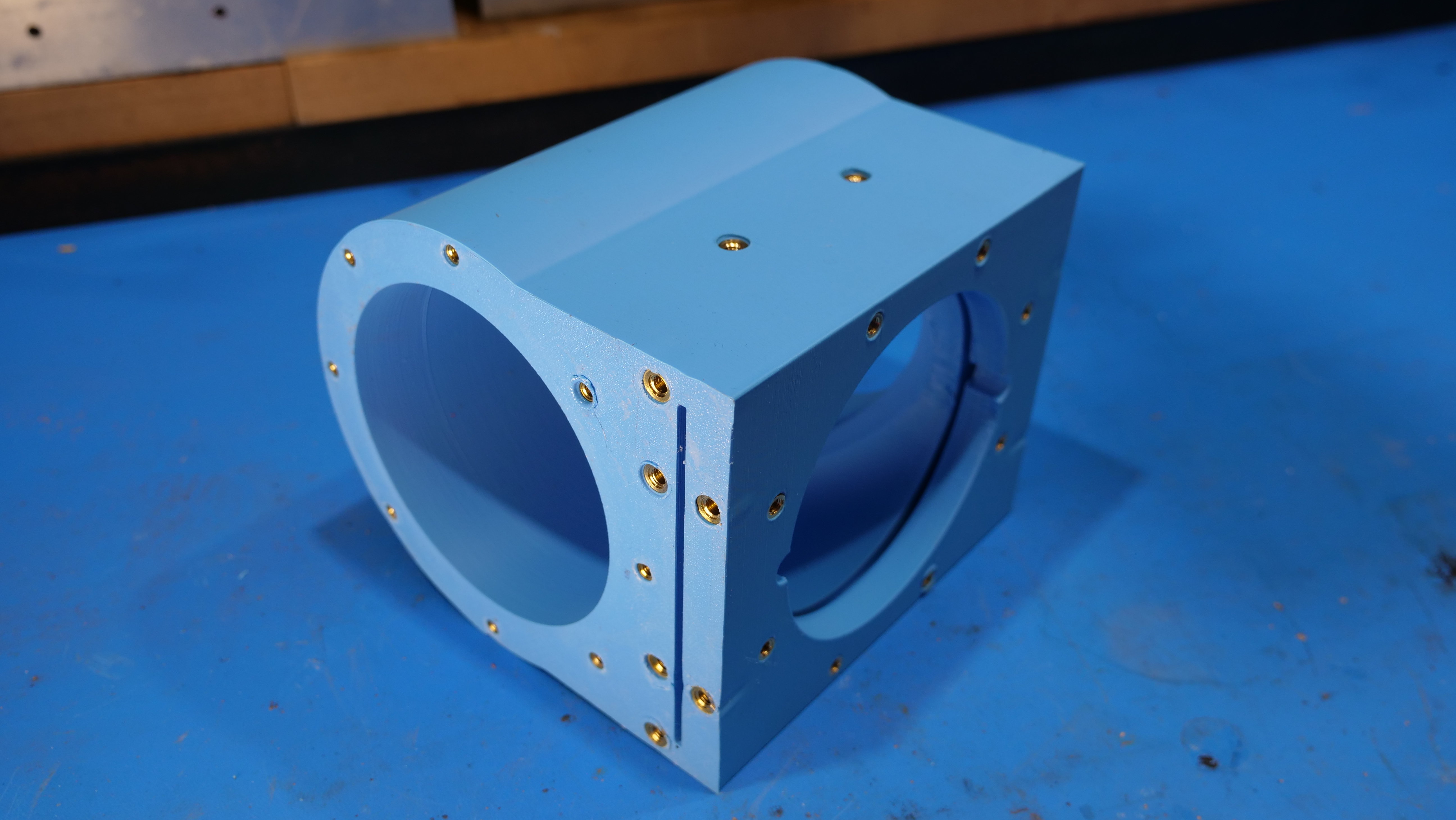
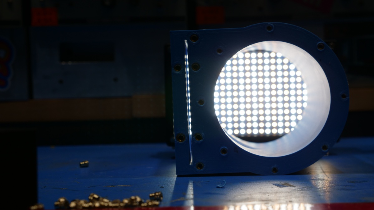
One important item to check is the blast-gate slot. It should be free of print artifacts. Shown below is a small shop light highlighting the gap to ensure we do not have print defects. 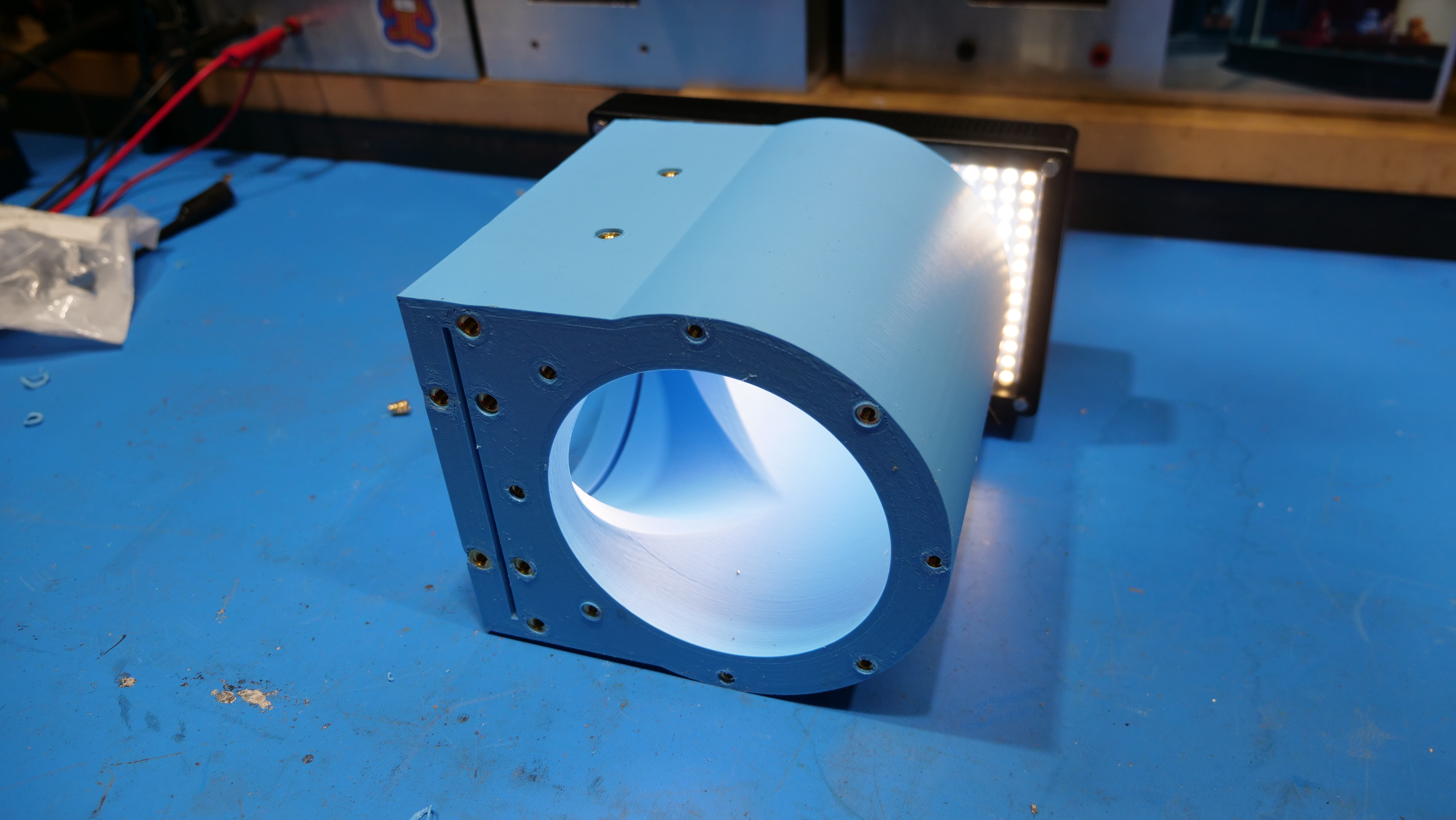
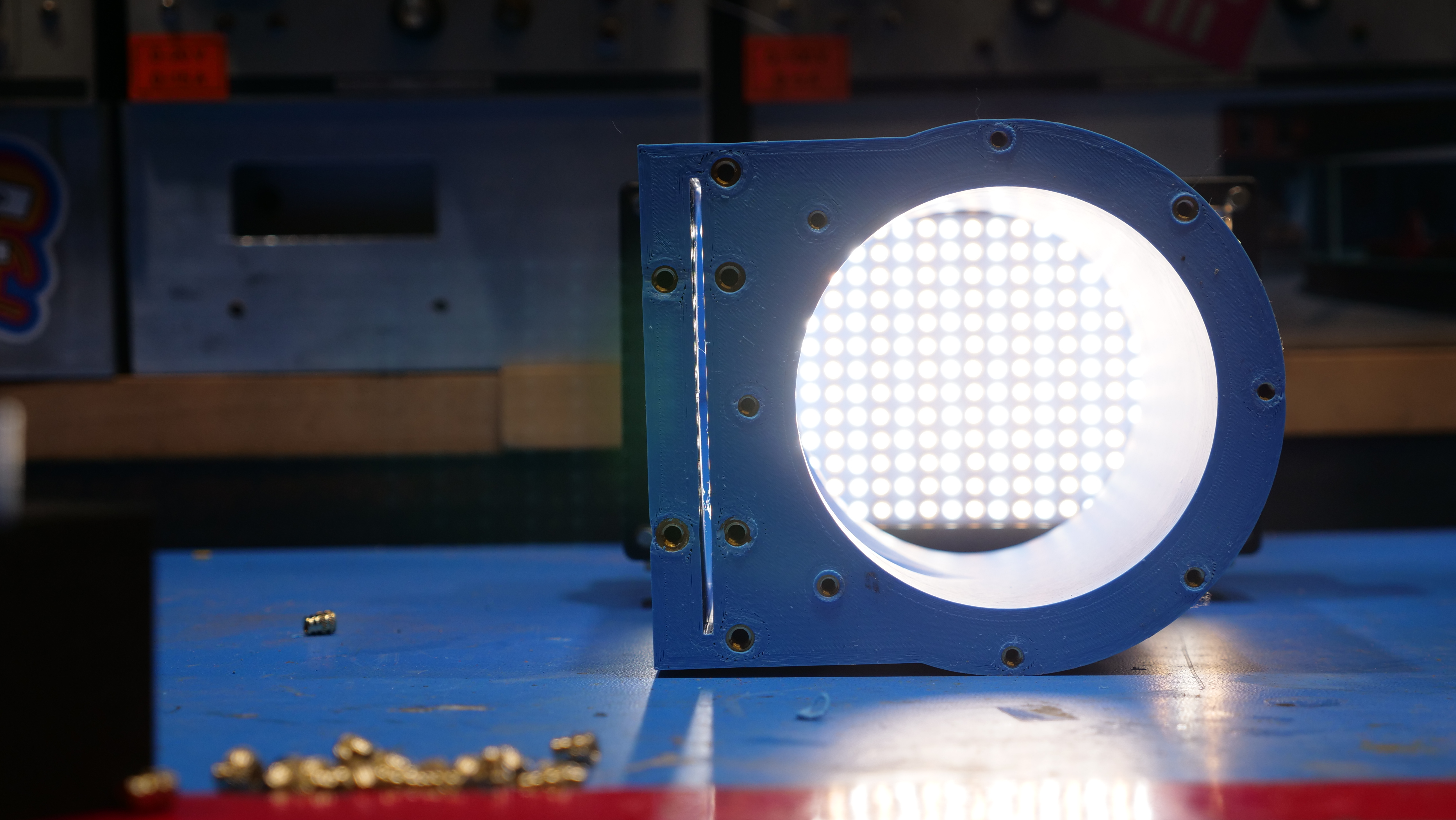
Removing Thermal Insert OverflowSomewhat controversially, I intentionally undersize the holes uses for thermal inserts to ensure full contact. As a result of this, there is frequently overflow above the insert itself. It can look terrible, but there's a fairly quick solution: a tap with a chisel. I used a simple 1/2 lb deadblow hammer and lightly fixtured the large print using a 10lb weight. The surface shown ends up without any protrusion, and in this case a large TPU part will be clamped here providing a somewhat air tight seal. The deform-ability of TPU permits some wiggle room on this seal. CAD FilesFor the purposes of compatibility, I've included solidworks (2025), step and stl exports, as well as the whole project as a pack-and-go. Bill of MaterialsA few specific hardware choices were made, and those parts are included below, along with other options that are mechanically compatible. Concluding Remarks
If you have questions or comments, ask below or send over an email. (be careful, im not responsible for your camera jumping off the table while excercising its shutter)
Have you noticed that there are no advertisements or ridiculous pop ups?
Want More?
|
Post your comments! |
|
Comment Box loading
|