Dane Kouttron
This project / writeup is in progress, check back for more soon!
1 kWh of portable energy in a standard-size toolboxMedical surplus makes for a great portable power solution
There's been a proper explosion of portable power stations of varying quality and size. This project explores an easy to assembly route, while using hardware that has appropriate QA / MBTF information available.
|
||
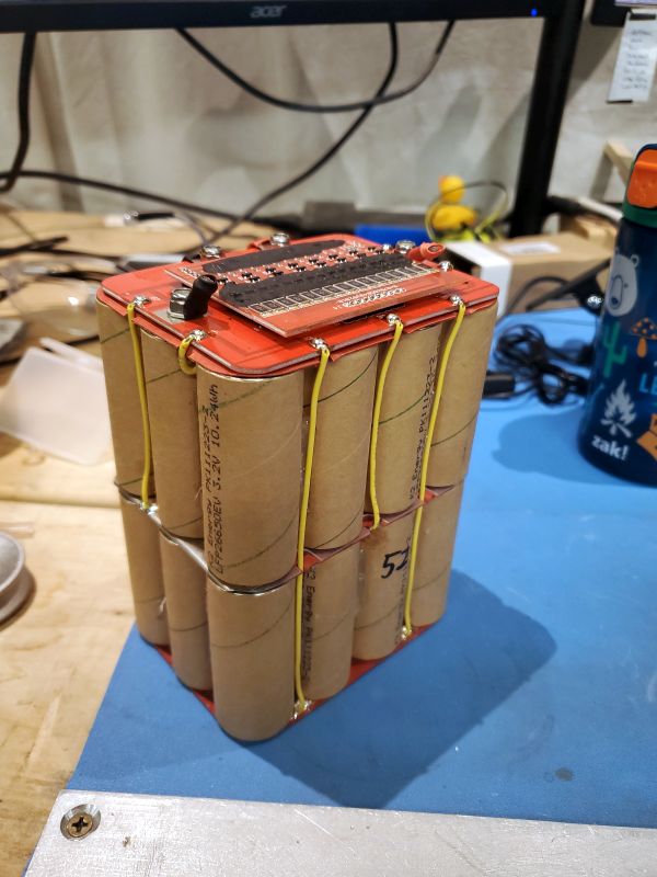
Quick OverviewThe K2 pack is pretty simple, its an 8S 3P configuration of 26650 cells with a simple analog BMS attached on top. UVP / OVP is provided by seiko ic's and the power handling is performed by an array of nch /pch fets. Some internal photos of the K2 module for reference below. Note its two stacked PCB's, the top board is voltage sense and current sense and outputs a mosfet drive signal. Balancing happens on the upper board. Note there appears to be current sense monitoring, so it's likely that these modules do have over discharge protection, its just unclear what that threshold is. This can be checked empirically with an electronic load, given how analog this board is it's likely a comparator - latch that's reset after charge is received. It wasn't apparent if there was a thermistor for under / over temperature discharge protection, but realistically its unlikely this will be an issue. Pricing and where to get these K2 ModulesThis little rectangles are common in the surplus market as they are installed on so many hospital medical carts. Batteryhookup generally has them in stock periodically, but they also appear on eBay. Mcmaster-Carr stocks brand new modules, and apparently instead of 9.6ah there's an 11ah variant. Comically I was able to get four of these for 100$ during the black Friday sale but even eBay make-offer 40$ is a fairly decent price. 100$ / kwh is not a great price if you're looking at raw cells but its a fantastic price for self-protected modules. 
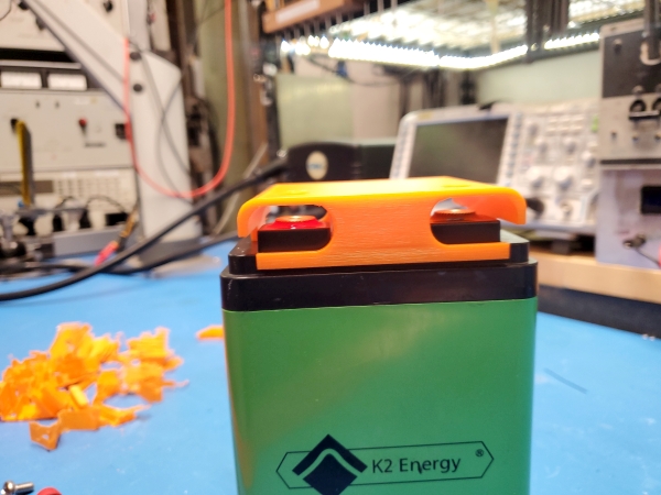
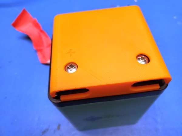
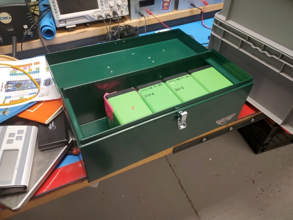
How well do the surplus modules stack up? Are they depleted on arrival, what capacity did they show up with? These are all great questions. The nameplate capacity is 9.6AH, however on a normal used module these appear at 8.5-9AH of capacity at a 1C discharge rate. The nameplate capacity is tied directly to how cycled the modules had observed in their previous life. at 9AH, we still end up with 950 usable watt-hours, which is realistically fine Quick Mock UPFor a quick spacing check, we can actually fit five modules in here, however for the sake of having space for extra hardware I'm only designing around four. The rough layout is a bit cramped. The 600W inverter is a fantastic fit, but the spacing for the 360W charger is a bit cramped. Both are mean-well brand which is stellar, as they make some great stuff. At 12A of charge current we net a 2.5hr recharge time, which is not exceedingly fast but also within the realm of useful, plug it in a few hours before a trip and you're good to go, but you won't be able to just stop at a rest stop and accumulate a reasonable amount of watt-hours, which is definitely one of the use cases for this thing. This is however fine for its use-case a budget backup box. Electrical Components and choicesPower inverter options:I wanted a power inverter that had an actual datasheet. There are so many options available in the 12V realm, and so many of them are fly-by-night vendors of questionable EMI output and dubious internal ratings. While the goal here is not to run an induction stove or huge well pumps, we need to find something with a continuous rating over 500W, with an actual datasheet and with an actual supply chain. There's no reason to build something like this and opt for an inverter that may randomly grenade itself. One of the major constraints is actually mechanical. The case itself is volumetrically full of battery modules, but the top part of the case is actually fairly open. I was not intending to be able to use this with the case closed, as it would end up thermally running fairly hot. The other constraint is the battery modules themselves, with a 1C discharge rating, or 9.6A / module, we can max out at 1KW for a rated discharge, however for modules in parallel you can assume that as one module fully discharges it will leave behind other modules to take up the load. This 'zippering' can result in the remaining modules seeing an excess of 9.6A. At 600W we are well away from the continuous discharge rate. First Contender: Meanwell A302-600The Meanwell A302 is a somewhat compact inverter with a 600W continuous rating, and 1200W pulse rating (for motor load, etc). At 600W we see ~20-25A of discharge current over the cell voltage range, this easily fits in envelope of 8 gauge chassis wiring, which makes things easier on cable routing. The inverter does not have a remote on/off but does have a simple front facing switch. Annoyingly the back mounting plate of the A302-600 does not fit inside the top lid of the toolbox, however it does come off easily, and with the back cover off it can mount directly to the roof of the toolbox. One point of note, modified sine is sometimes a detriment for power supplies, but for this application its realistically fine. Pure sine inverters are somewhat larger EMI generators and generally always have higher quiescent currents than modified sine. I've yet to run into devices that are picky enough to refuse to use modified sine inverters, but will sometimes observe LED / CFL lighting flicker more when on a modified sine supply. The inside of the inverter is really basic, actually surprisingly basic and not very electrically dense. This is somewhat good and bad, as its unlikely to run warm due to the large open air routes thru the case, but a more modern design may have fit 1+kw in the same form factor. The extruded case with heat sinks is very nice, and is likely oversized for this application. We see three 25A ATO fuses in parallel on the DC input link, so the inverter would open circuit at ~1800W on the DC input side. Otherwise we have the fairly standard topology of a two step DC inverter: Take battery input voltage and generate ~140VDC, take 140VDC and make 60hz 110vac. There does not seem to be any inrush protection for the DC link, but there is also not a lot of DC bus capacitance. Inrush issues generally are the failure point for most of the small inverters, as the capacitors are drained to 0V, and you immediately connect a fairly solid (low impedance) DC source and the slug of current exceeds the capacitor inrush limits. While most electrolytic caps can survive this a few times, they eventually fail and disassemble or vent. How well does the inverter fitBattery Protective CoversThe one issue with having the K2 Packs sitting with their terminals facing the case is the pack shorting out against the metal case itself. Its possible to 'put some padding / foam' here but we have technology, lets print out some covers that protect this from shock and vibe issues. The model is included below, I printed out covers on an UP Box+, however this is printable on any number of machines due to its size and form factor. One of the design choices I made was to make sure that i could still get at the screw terminals, and allow for a wiring path for cables to escape from the covers. This really makes assembly a lot easier as the wiring can happen while still allowing the lugs to be tensioned in place. Due to the layout there's a bit of support material to remove from each of these prints but the output quality and extra electrical protection really makes a difference. 

Have you noticed that there are no
advertisements or ridiculous pop ups?
|
Post your comments! |
|
Comment Box loading
|

