Dane Kouttron
Project Started: 08/2024

Why are Gyros not cooked with a Gimbal?Have you ever noticed that a Gyro sandwich is only cooked on a single axis?Cooking food uniformly has been something that mankind has approached a number of times over the centuries, oddly, it inspired all rotary motion advancement. Leonardo da Vinci devised a 'smoke jack' that used the hot air from a stove to rotate food in the late 1450's [1] . The first steam engine was put to use, not pumping water or grinding wheat, it was used to rotate Döner kebab in 1551 [2]. In 1748, Benjamin Franklin developed an electrostatic motor, and lo what did it rotate? A turkey rotisserie [3]. The first engines and motors were put to work improving our ability to cook a meal. So when you go to a Greek or Turkish restaurant, you would imagine in this modern era that a gyro, either meat or vegetarian, would be cooked in not one, but three axes. Our forefathers lacked gyroscopic gyro technology, and maybe, just maybe in this chaotic era this is what we need to advance food technology into an age of enlightenment. |
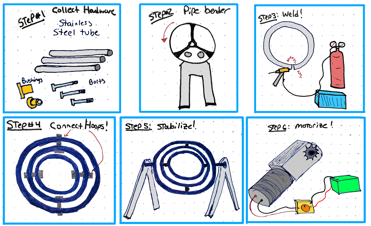
How hard could building a multi-axis rotisserie really be? Here is the rough plan:One of the major instigators for these kind of projects is surplus hardware. After asking around I was able to find some free food-grade stainless tubing. With the pricey part of this project in-hand it was time to start determining the best way to quickly turn this idea into reality. I devised the rough plan shown above: Bend it into hoops, connect with hardware, motorize & model the system dynamics, and finally make some delicious and entertaining food for friends. This particular write up involves a lot of fabrication and as a result this page is a bit media-heavy, efforts are made to reduce file sizes, but there's a lot of short video clips to show how things were made. Short form video animations can be remarkably information dense. Making noodlesWith the 1" OD tubing in hand, I was able to get access to a tube roller, via the ever-excellent DLAB-Jack. The process seems straightforward, you push some tube through the rollers, a manual hydraulic jack applies off-axis pressure, and the tube bends into a perfect circle, right? Curiously that's not particularly what happens. While the tube bends, there is not really anything that constrains it from squirming and wiggling out out of axis with the hoop. To compensate for this, you as the operator, move the tube incrementally, adjust the axis of the hoop, then move the tube incrementally more. Some important points of note, if the hydraulic pressure is adjusted at all mid-tube, it will leave an annoying discontinuity in the tube, and as such it's important to only increment the hydraulic pump towards the ends of the tube. If you're interested in duplicating this project, it is important to have the right size wheels for the tubing you plan on using. The actual tube roller is this model [link] with an upgrade kit from here [link]. Thanks again to DLAB for having this device in-lab and available to use.
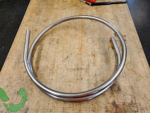
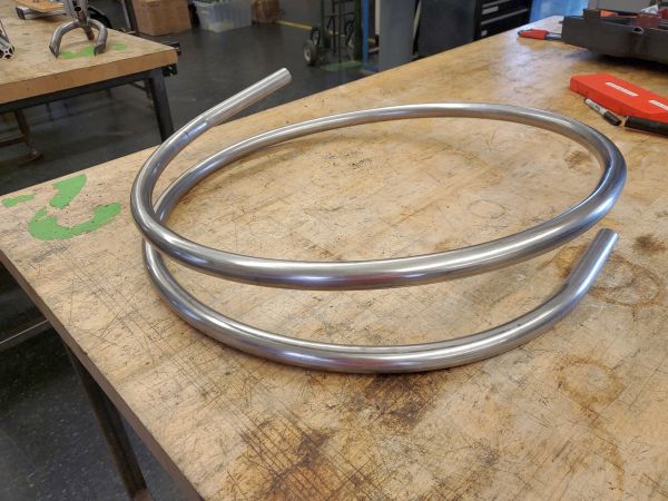
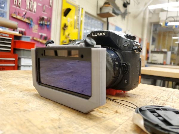
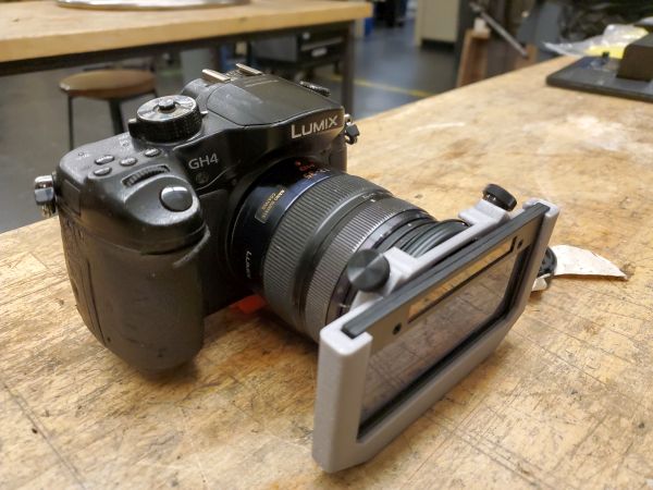
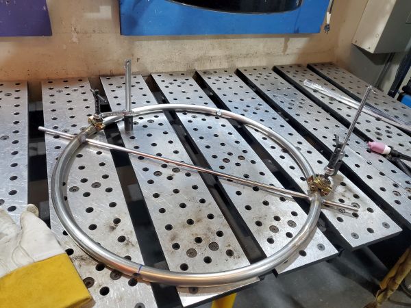
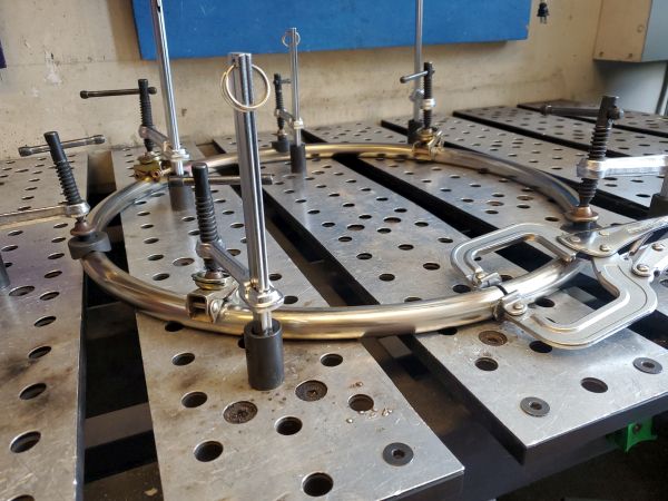
While the SWAG upgrade kit does mate to a harbor freight pipe threader, I found that the pipe threader's fixed speed was too hard to control manually and ended up opting to just use the default large hand wheel. While this was more of a workout, it did allow a lot finer control. It gets more curious though, you can not actually just 'roll a ring', as the tube roller itself requires some space on the ends of the tube that topologically remain in their initial flat arrangement. You want the ring to be continuously round, so you effectively need an overlap area. As the tube cannot occupy the same space as the section before itself, it needs to be off-axis. As it turns out to make a hoop or ring, you need to first make a noodle, shown below. Ignoring the fact that there's a pretty significant off-axis tube, looking at the whole thing from above, it does actually look pretty good. Now's the time to slice into this thing and try to line up the final shape. I used a hacksaw and a file to get the tubing's end to match up, and it came out fairly close. Initially was planning on using an angle grinder but found that the hacksaw and file had a bit finer control. Given that these would end up being welded together, attempts were made at minimizing the gap. As you may have guessed, a thick walled stainless tube that was bent into a spring shape, does in fact want to stay as a spring. This is fairly visible on the welding table photo below. It is pretty bad when you look at it from the side, time to convince it to be more planar. There's a bit of work cut out for us here, the hoop is quite twisted. The off-axis height difference is about +1 inches at the maximum, which tracks as the tube was physically generated as a coil. DLAB is such a wonderful shop space, and the real GEM is the welding shop. It's the size of a dorm room but exactly what it needs to be, it's not cluttered and everything has it's place. It also has a comical quantity of nice clamps. This is great as I really needed a lot of help making this planar. I ended up using 6 table mating clamps and one vice grip to constrain this hoop to be planar to the table. The pivot friendly clamp heads are amazing for this exact task and I really like them. The tubing did eventually almost mate together. The gap for the seam was a lot more than i had hoped, but it was important to keep in mind that this was not a structural device, jumping gaps with a TIG welder is not terrible if it's a prototype. Relieving StressStainless steel can be annealed, or softened by bringing it up to temperature. The mystery tubing was labeled 316L, which has an annealing temperature around 1900F or 1000C. This is within the normal propane torch temperature range, so with some directed heat we should be able to de-taco this hoop. The footage below is shot from two separate angles due to space constraints, but it is synchronized over time. I did want to establish a point that the stainless tubing did discolor but did not physically glow while it was being annealed. Unlike mild steel, 900-1000C stainless is just a dull dark red. A lot of folks view this content on vertically oriented mobile phones, as of recent, so here's the footage lined up vertically. This whole process actually worked, it consumed quite a bit of propane, but the first hoop looked splendid! After waiting a full hour for everything to cool down, it was indeed a fairly flat hoop! Welding HoopsAs a quick aside, I did make a device for recording welding recently and this was as good of an excuse as any to put it to use. This is an update to my 'welding vision' project [link], I upgrade from a budget 13$ welding glass insert to a modern version and it makes a huge difference. The view is no longer greenified, you can see nearly perfectly before welding and while welding it is remarkably more clear. You can probably film welding with a camera alone but you do risk sensor damage, you're pointing an optic at a comically bright light source, its surprising that a camera viewing from a distance does not result in sensor errors. This adapter was intended for a micro 4/3 lens system, but it is adaptable for other lens versions. Check out the project page for more information and 3D printer files so you can make your own.
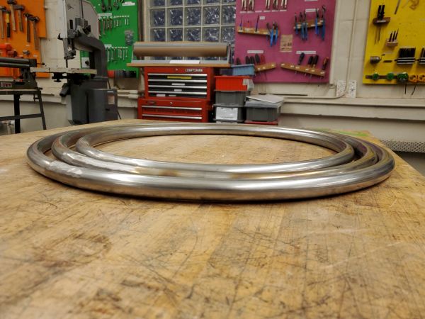
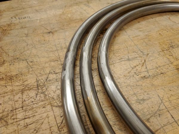
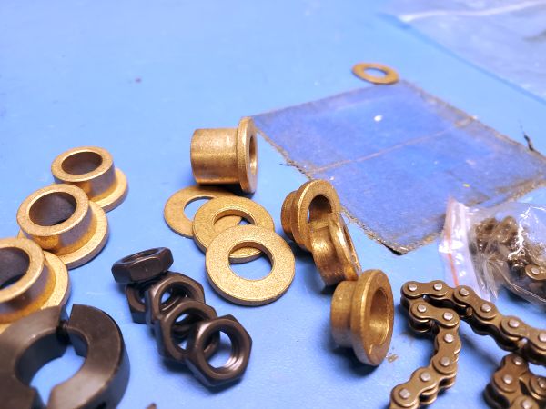
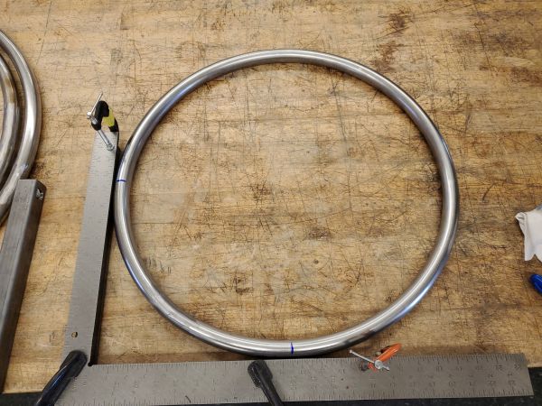
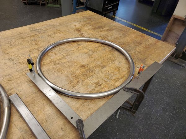
Back to hoop making business! This particular footage was unfortunately filmed in an annoying MTS format, so there is a bit of interlacing, subsequent welding footage below is corrected. But look at how not-green the footage is, this is right from the camera without color correction!. I do not want to bore the reader with all the footage of making two more hoops, so here's the result: Three hoops, with ~0.5" spacing in between each side. The first hoop acted as the inner, and subsequent hoops were the two outer ones. It was remarkably hard to get the spacing right, as the geometry of squishing a tube to shape, while not having exact spacing, due to the tube-ends being somewhat variable in length. As a result there was a lot of back and forth iteration, which was time intensive. Finally it was time for the stack-up and bushing assembly. Next up is some flap-disk grinding, this is purely for aesthetic purposes. I really like this flap-disk [link], it's a nice medium between coarse and fine and for stainless it seems to do a fantastic job. I proceeded to clean up the welded joints for the other two hoops After grinding the weldment area, admittedly hastily, we end up with three fairly flat, fairly equally spaced hoops! Given how noodle-shaped these were at the beginning I was quite happy how they turned out. Bushings and alignmentI did have a plan for keeping everything happily aligned, the hurdle here is a mis-alignment could cause things to not rotate smoothly, and given that only one axis of this apparatus is driven, having one axis less-free to spin about would result in uneven cooking. So my plan was to take advantage of the nearby waterjet and make cute little brackets, with features that would be easy to align, or so I thought. So here was my goal, an easy-to-fold bracket which would hold a high temperature graphite bronze bushing. I've found that is important to document successes and errors, so here's the bracket that i thought would solve my problem: There were two initial problems, I made a CAD transcription error on the radius of the cutout and the length of the part. With the shoulder bushing installed there was not quite enough space for everything to fit in. This became a bit more of an issue as even if the part was re-made the space available would result in both should bushings riding directly on each other, with no intermediary bushing in between to limit friction. This somewhat came up as I knew the hoop making process was not going to be a process that had any form of tolerance, so I did not start with a full CAD model, I intended to CAD after having the dimensions of the rings, and considered that ~0.5" gap between each was sufficient. To speed up the assembly process I had waterjet these parts before finishing each of the rings. Bushings backup planThe backup plan is to use much longer bushings and ignore the weldments.While this is not quite ideal, the flange bushings do not seem to mind if they are not sitting flush up against a flat surface. If the system is under-constrained, the issue of eccentricity should be resolved. This opens up some space to allow planar bushings to help reduce friction between the rotating surfaces. I opted for a mix of 1/8" and 1/16" thick graphite bronze bushings, as they were rated for the temperature and were less likely to leech out any lubricant chemicals. Shoulder Bolts have large headsOne other artifact of starting out with a napkin sketch instead of a cad model, is the enormous size of the 1/2" shoulder bolt heads. The shoulder bolts themselves were there to act as a ground round surface for the bushings to run on, they were not holding anything enormous in place. If there was a shoulder-pin I would have gladly used that instead. The 1/2" spacing quickly evaporated with these enormous shoulder bolt heads. I'm not transmitting torque through the bolt and do not need to tension them, so off with their heads! This felt a bit wrong as these shoulder bolts were not by any means cheap, but alas I did have a fairly short timeline to finish the mechanicals. So I turned down the shoulder bolts to have a 1/16" thick head, plenty for them to still act as a shoulder-pin. As it turns out these shoulder bolts were in fact alloy steel that was Rockwell C32, so this did take a bit. I was also cautious to not over tension the lathe chuck as it was gripping on the ground round bearing surface that I was intending to keep smooth. The next step was to attempt to align the mounting holes for each hoop. We can somewhat get away with trickery here. An architect's square (suspended off the table to the height of the tube) is a great tool for this exact application. The perpendicular holes need to be equally spaced around the circumference . Accurately measuring circumference of a hoop is unpleasant and difficult to do accurately, so I came up with the following. Mark one spot on the tube, rotate roughly 90 degrees, and measure that location on the X axis of the architecture square. Now mark the same value on Y. rotate the tube 90 degrees again, mark at the same spot. Rotate 90 degrees again and the end spot should be at the same measurement as it was initially. If you end up overshooting or undershooting, increment or decrement the offset on the carpenter square and try again. This iterative approach sounds cumbersome, but nominally i was was within 0.22 degrees of perpendicularity after the second attempt. We're all marked up with perpendicular hole locations, so next up is making the plunge and drilling through the tube. With the shoulder bolt sorted, time to punch through these hoops. Given the size of these they do not quite fit in a drill press, either the clamp does not clear the bed or the hoop does not clear the motor, so this is going to be a hand-drill experience. I did put in a bit of effort to try and maintain perpendicular when drilling through the pilot hole, but that can be difficult. The bushing-sized holes however were a step-drill activity, as shown below. I specifically purchased a step drill that was intended for stainless as I would have imagined a normal mild steel one would suffer after the first or second attempt. The bit survived the punishment, which is good as it was not cheap. Spinning Up:This process was repeated many times, and at the end of a few drill battery charging cycles, we now have perpendicular holes going through four portions of this hoop and subsequent hoops. I will make a note here that getting the hole perpendicular with the width of the tube is difficult, offsets from the center are not the end of the world, but will result in a differential mass on either side of the hoop's axis and as a result a preference for it to flop to one side. I was waiting on some 1/2" OD shaft to appear, and too impatient to not find a way to test out the first axis. I did find some metric threaded rod that was close enough and while it probably marginally damaged the inside of the bushings, it was worth testing to see how freely it would spin. With a basic hand spin, it flipped about for 20+ seconds, which seemed pretty good for rotating on a not-smooth shaft. The hoop also seemed to stop without a preference as to which side it ended up on. The metric threaded rod was only held in place on one end with a simple bench vice, so the opposing end did have a bit of wiggle. I did notice, watching this video, that the hoop was slowly inching closer to the vice as it followed the threads when it stopped, so it is possible it could have run much longer in retrospect. If the threaded rod was constrained it would have likely kept spinning for longer as well, some energy was going into the wiggle at the unconstrained end. Either way this was the right step forward. Time to continue on and see how well the shoulder bolts and bushings do for two concentric hoops. There is a bit of wiggle, but for a first pass this seems pretty good. At this point in the build I was waiting on some more intermediate bushings, which should help with the shoulder bolt to bushing mate. The intermediate bushings also help set the tension on the axis, which should limit the wiggle. The last axis that needs fabrication is the frame mating portion. This rotational point is static, or directly coupled to the outer hoop. This could be accomplished with a shoulder bolt welded in place, but that does become really difficult to fixture. You basically want a rod going through the whole outer hoop that you weld in place, taking care to not thermally overload one side or the other, and then, after it's cooled down, remove the center part of the rod. I was hoping to find 1/2" OD stainless tubing, specifically tubing that did not have a weld-seam, however that turned out to be fairly pricey, so i opted for 1/2" stainless shaft. Welding medium wall tubing to a solid shaft can be tricky, specifically for aluminum, however due to stainless steel's terrible thermal conductivity it was remarkably not bad. The holes are over-sized for the 1/2" rod stock, specifically to allow it to fit without bending. I cut some of the 1/2" rod stock to size on a cold saw, kept it contiguous for welding and then removed the inner portion, Again, a lot of care was taken to make sure that the stainless rod that was used did not have an odd or offset torque on it, I was really concerned that once the inner section was cut out, the hoop would un-spring and leave the two ends no longer concentric. Actuating one axis:I know you're asking how exactly the outer hoop is driven, It's not particularly groundbreaking. With the weldment ground down and cooled, the drive assembly sits coaxial to this new welded axis. Making it co-axial helps reduce any offset or error on the chain drive, as the two are intentionally made co-planar by a part that rides on a bushing. The motor assembly was fairly simple once the driven axis was complete, I was concerned that once the rod that was used to provide the driven axis was cut it would spring to off-axis, fortunately, due to the open tolerance on the mating holes for the shaft, the weldment did not introduce any warping.
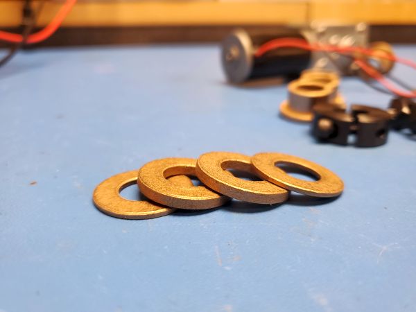
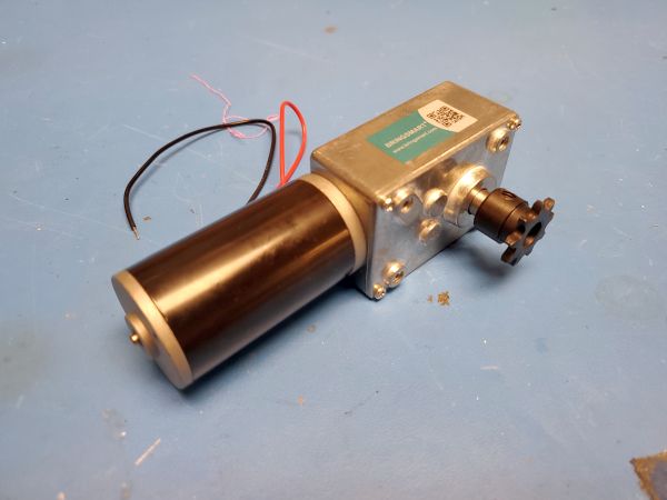
The CAD model for the motor assembly is fairly basic, the motor sits on an aluminum bracket that features a bushing, the bushing keeps the bracket perpendicular to the rotational axis, and the motor sits perpendicular to the bracket. A chain reduces the motor output from 40 RPM to 10 RPM at ~14VDC, which is fairly reasonable for cooking. These motors [link] are available in a number of gearing ratios, which was fortunate, I was initially unsure what RPM would be reasonable. The amazon motor mounts are not quite perpendicular to the motor shaft, likely just an artifact of the cast shell that it is housed in. To compensate for this I shimmed the motor with some thin washers. The chain drive is tensioned by adjusting the position of the gearbox mounting screws. Given that this is only single-supported, there is a bit of wiggle room for the leg mounts.
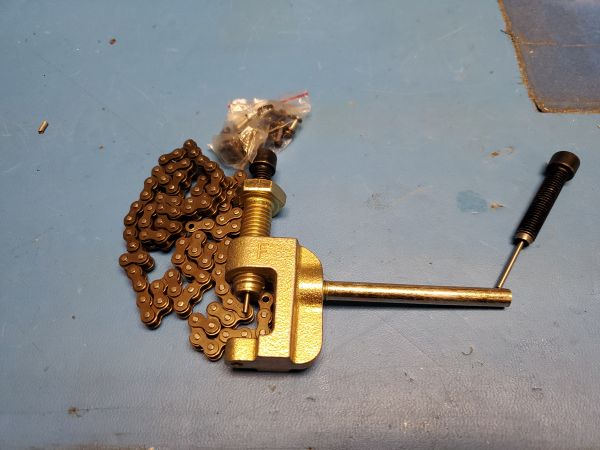
Not shown in the quick CAD display is the chain assembly. Fortunately #25 is sufficient for the loads of this project, which also allows for some small sprockets and chain. I grabbed a #25 chain with tool kit from amazon [link] and made the correct length chain for the drive motor. For a cheap chain tool it worked surprisingly well. The drive sprocket is a 10 tooth, while the receiving sprocket is a 44 tooth, resulting in a 1:4.4 gear ratio, our 80RPM motor is now geared down to 18RPM at 12V no-load. For bench testing I used a bench-supply to note what the current consumption was and what speeds I was able to observe under no-load conditions at various voltages. With the motor brackets fabricated, the motor chain drive set up, and still waiting on bushings and 80-20 for the uprights, I decided to do a quick bench-test using impromptu uprights made from some 1X2 wood. This was, very much a bench test as the wooden uprights were quite un-constrained. There was some wobble as a result. The lack of intermediary bushings was really visible here, the axes were not spinning as smoothly as I would have hoped. One point of note was the "MEAT" stimulant, or rather the 6 lb brick of 80-20 extrusion. The mass was relatively small in relation to the mass of the corresponding hoops and it was also somewhat centered, so gravitational forces did not have a significant effects. So we do need some mass differential to introduce more system chaos
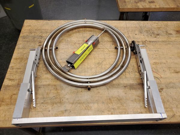
The 80-20 finally appeared, now to build the uprights Next up i tested out an offset mass for the food mass stimulant. in this case it was a 8 lb chunk of steel tubing, labeled appropriately. The mass is captured by the food hooks that I intended to use for the first live test. These [link] are adjustable on a square 3/8" rod, which makes setup significantly easier, while still constraining everything. I chose to use smooth 80-20 mostly for aesthetic reasons, but also to allow for other extrusion to act as adjustable legs. This allows for all four legs to have independent lengths to accommodate less than level fire pits, or rocky areas. For the first revision I used simple hex bolts for locking the leg height, but i will likely move towards a thumb-screw or something that does not require a tool to adjust the height. Admittedly this spot is near the thermal source so, something that could be adjusted with some heavy gloves should work well The bottom-most extrusion length was chosen to add around 10 inches of adjustment on the leg height, this still leaves some space for the 80-20 extrusion nuts to remain in the channel and hold the assembly in-place. Making gyroscopic gyros: The first live demoAn end of summer party approached, time for a live test. Are gyroscopic gyros the future? We have ~40 test subjects and some beautiful weather. Mr Fred masterfully sliced and diced our slowly roasted meats, Brandon went to town prepping the pipe of pitas and otherwise folks served themselves. It was remarkably tasty, especially thanks to all the prep work Jack Whipple put into the meat! I did not get a lot of shots of the gadget in action, there was plenty to do running a large party, but these shots really are wonderful, folks soaking up the weather as a gadget whirrs on in the foreground. Audio is included in the clip below but is auto muted. I mean look at that Gyro Sandwich, being modeled by the ever excellent Adam / Matlab The Greek. Did i end up with a 100 pack of tiny Greek toothpick flags? Yes, was it worth the 4$? Totally. Bill of Materials: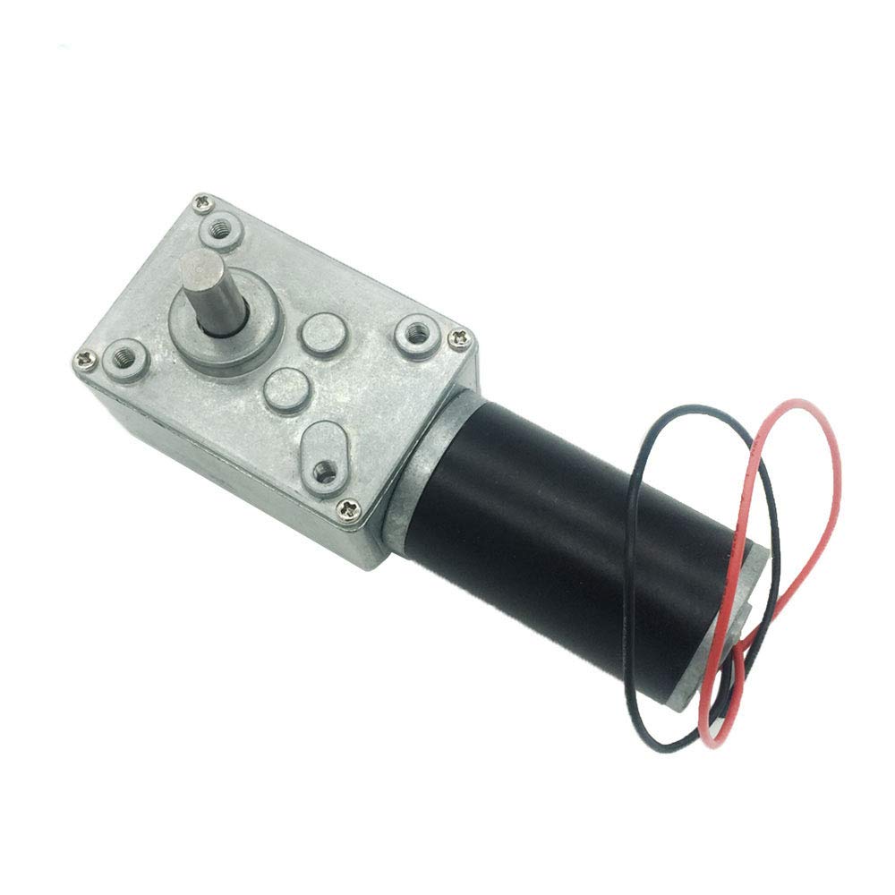
Simple 40 RPM Gear Motor [Amazon]This gear motor surprisingly held up without issue for three hours near an open charcoal pit. This motor is not back-drive able, which i was concerned about. Ideally I find something that's planetary-driven instead of worm-driven for a second version. 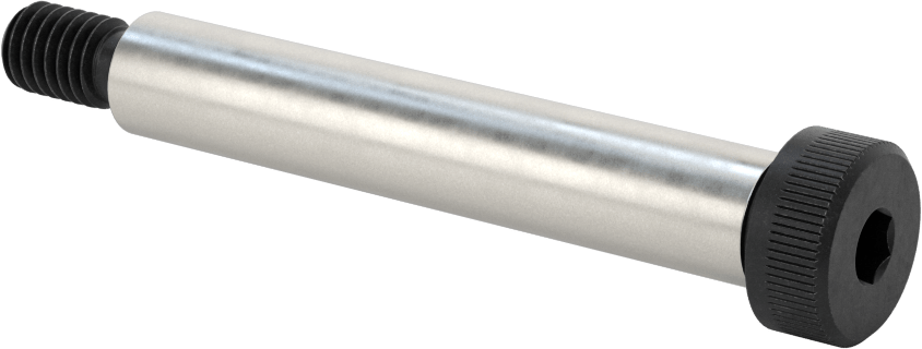
Shoulder Bolts [McMaster-Carr]These are 1/2" diameter shoulder bolts, I ended up using both the 3" shoulder length and the 3.25" shoulder length, due to the offsets when fabricating the hoops. In total there are four 3" shoulder bolts, one 3.25" shoulder bolts and one 4" shoulder bolt. 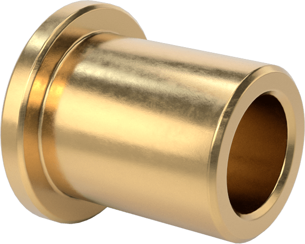
Bronze Bushings [McMaster-Carr]A few versions of these bushings were used to provide a low friction coupling between the hoops and each axis. 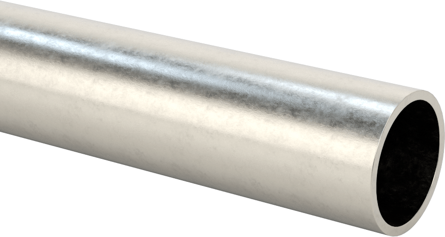
Stainless Tubing [McMaster-Carr]I did not purchase this tubing, I was lucky enough to find it in a lab clean-out / lab basement. Thick walled stainless was a lot of effort to bend into hoops, save yourself some time and see if you can use aluminum for your project. 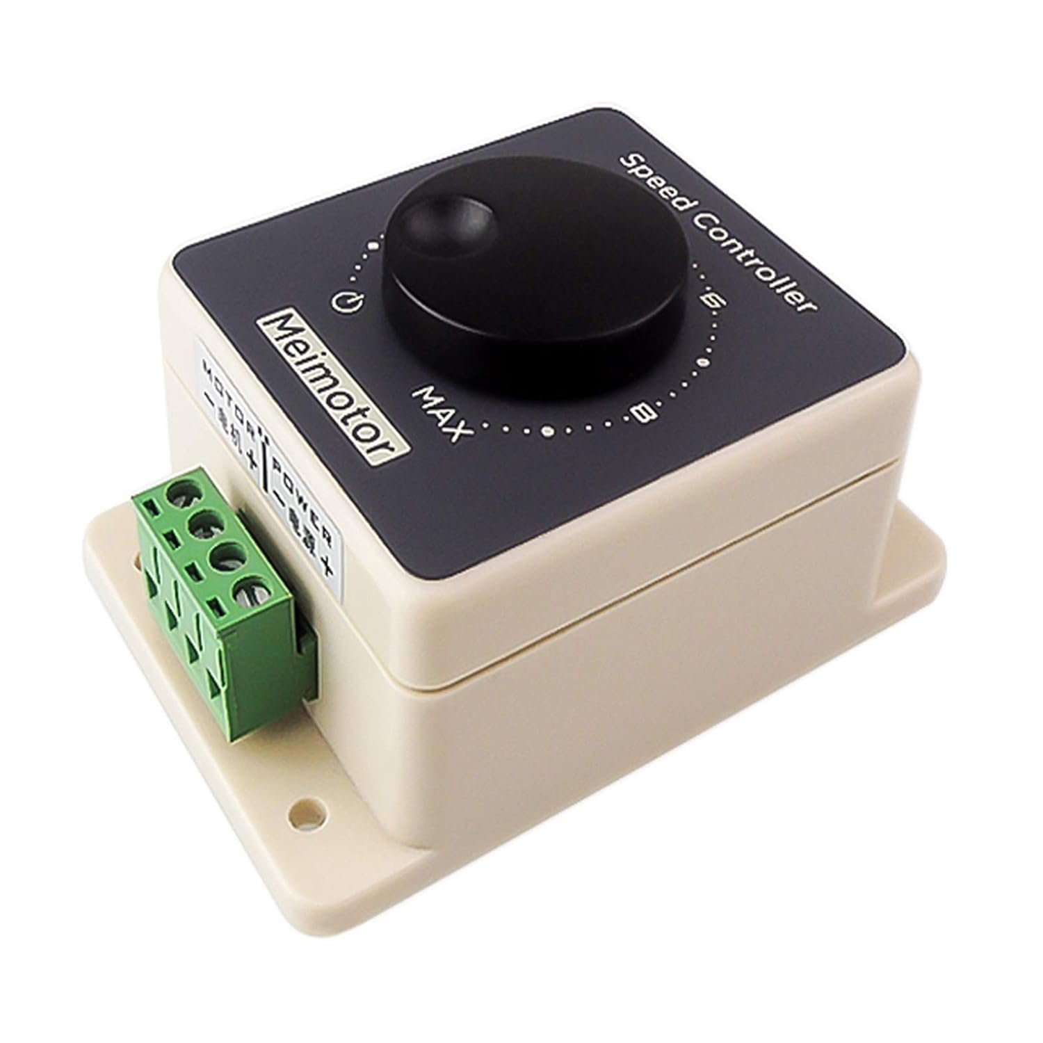
Motor Controller [Amazon]Simple PWM motor controller with current control, this ran from a 12V LiFePO4 battery with an in-line ATO fuse. This was helpful to get the right rotation rate, as the chaos for this system is driven by the offset mass + gravity, spinning too quickly pushes you into gimbal-lock conditions, and too slowly does not have adequate activation energy for higher order motion. 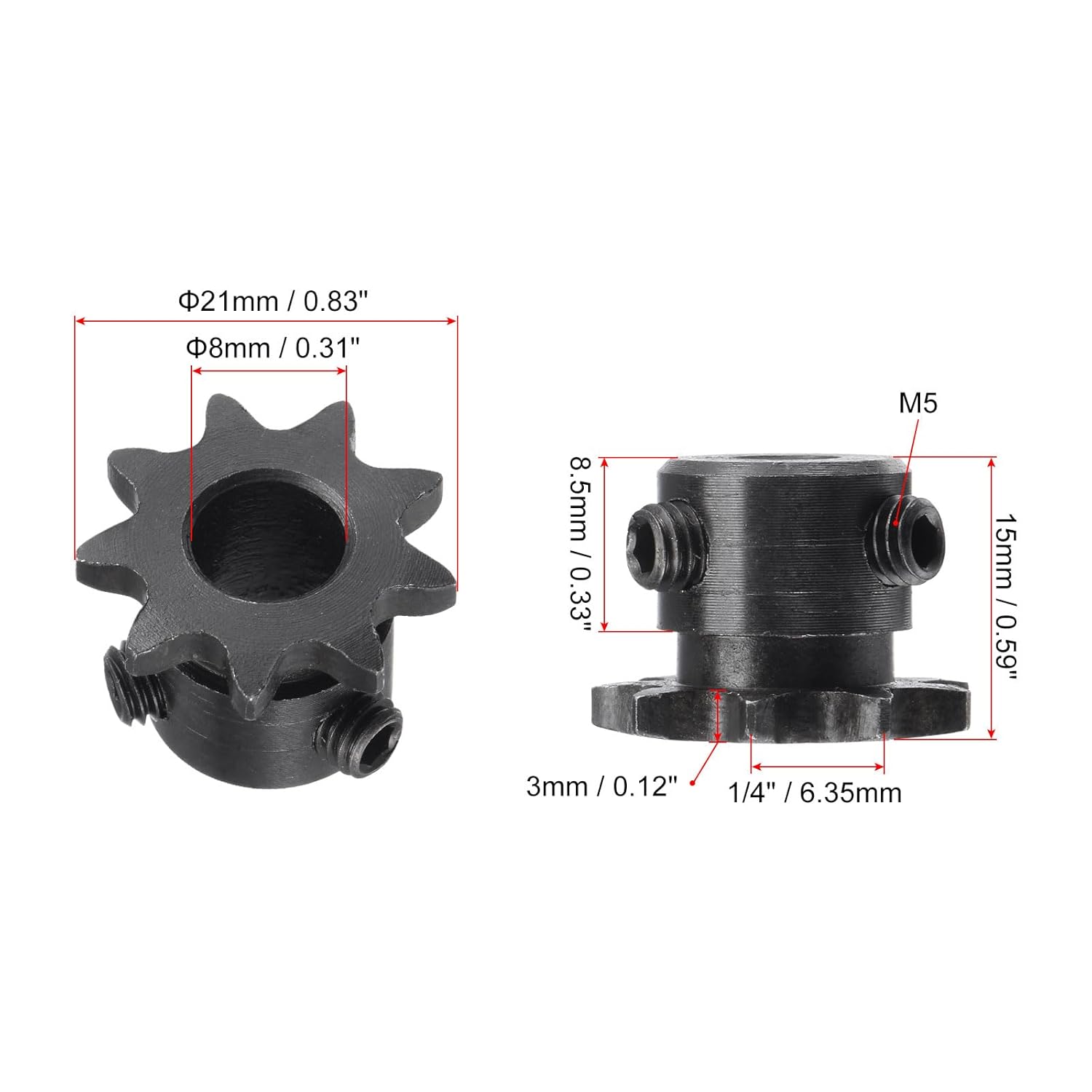
Sprocket [Amazon]Again, this sprocket was chosen due to availability and also to help achieve a higher reduction ratio, equivalent chain and 35t version of this sprocket was used for the hoop connection sprocket. Concluding Remarks:
Have you noticed that there are no
advertisements or ridiculous pop ups?
|
Post your comments! |
|
Comment Box loading
|
