
Dane Kouttron
Project Started: 01/2026
Building a Stabilized "Chase Camera" Rover
You stumble on a weird robot chassis in an industrial warehouse. Its adorable, enormous and will likely be scrapped.
Time to adopt this curious contraption and turn it into something cinematic. I was wandering around an industrial auction warehouse and stumbled on what looked like an enormous RC car with some elaborate scissor jack oddly attached to the top. The moment I spotted it I knew exactly what it should become: A distant off-brand cousin of the Freelfy Tero. The Tero can be seen all the way back in the early rocketjump days [Link] where they used the platform to get low to the ground moving shots in their skits. The following details all of the intricacies of building a chase camera from the ground up, using a mix of off the shelf items, used hardware and a pile of printed parts to bind them all together. There was a lot of trial-and-error in this build, and those errors are documented in full detail. As a result this writeup is a bit long and media heavy. |
The PlanQuad-rotor drone shots taken low to the ground are difficult: GPS altitude is fairly rough on accuracy, and obstacle avoidance can get significantly more difficult versus just flying over the everything. Cinema rover drones are less common but do get around a number of these problems, especially if the subjects are not high off the ground. As a fan of karting, lightweight contraptions and photography this seems like a pretty good project: Tackle a mechanically stabilized video platform, pilot it remotely and capture some outdoor action. To do this we need three major things: 
There's also A LOT of intermediate hardware to glue everything together, but the actual goal is to get shots where the subject is moving but in view. This can be used for anything from zooming down a frozen lake on a mad-max-ian contraption or observing suspension geometry up close on a test track. 
A chassis that can hold a modern DSLR does need to be fairly large to support both a stabilization mechanism, like a 3 axis gimbal, while not flipping over. Here's a 1/5 scale rc vehicle with a large dude for scale, used as marketing for Losi 5 platforms. These things are quite literally 1/5th the scale of a full size vehicle. The size both has advantages and disadvantages, namely everything is big and heavy. Big and heavy is great for preventing the whole platform from flipping but it does result in everything else becoming large, from the control electronics (VESC) to the comically large 3D prints. 

We all have that friend who forwards dangerously good deals on hardware, either oddities on marketplace or curiosities on Craigslist. I was fortunate enough to be linked to a very good deal on a completely functional Movi M10.Thanks Bayley. This model was Freefly system's first go at a full size camera gimbal, proceeded by the M5 and then the M15. Either way for ~124 USD, it was a bargain and got some use at the 2025 Ice Racing Outing. This Gimbal was the first born son of the Gimbal whisperer, Shane Colton, and it's very much a passion project. The fact that it's still being manufactured and iterated on, nearly a decade later, is a testament to how well it works. 
The M10 is shown here with some support details here To make development quicker, I'd really like to be able to remove the gimbal-camera-transmitter assembly as one unit, versus having a few dangling cables for power and communications. To do this we do need an auxiliary power supply. There is a happy medium between the gimbal's operating voltage range, the receiver's operating voltage range, the camera's aux power supply voltage range and the wireless video transmitter's voltage range, and its a convenient ~14V, or rather, the DTAP battery range of 12-16.8Vv 
While there are a lot of things to power, there's a bit of attention to detail to ensure the total mass is kept low, especially on the most actuated portion of the gimbal. This cart needs to relay back video information over a long distance. Traditionally this can be a game of quality versus latency vs bandwidth. I'm also limited to what my video source is, which likely a DSLR with an HDMI output. Traditionally I've used the 900 MHz band for long range control, but for video, 5.8 GHz really does seem appropriate. I was able to find a matching pair of Amimon CONNEX wireless HD links intended for UAV's for <100$. 
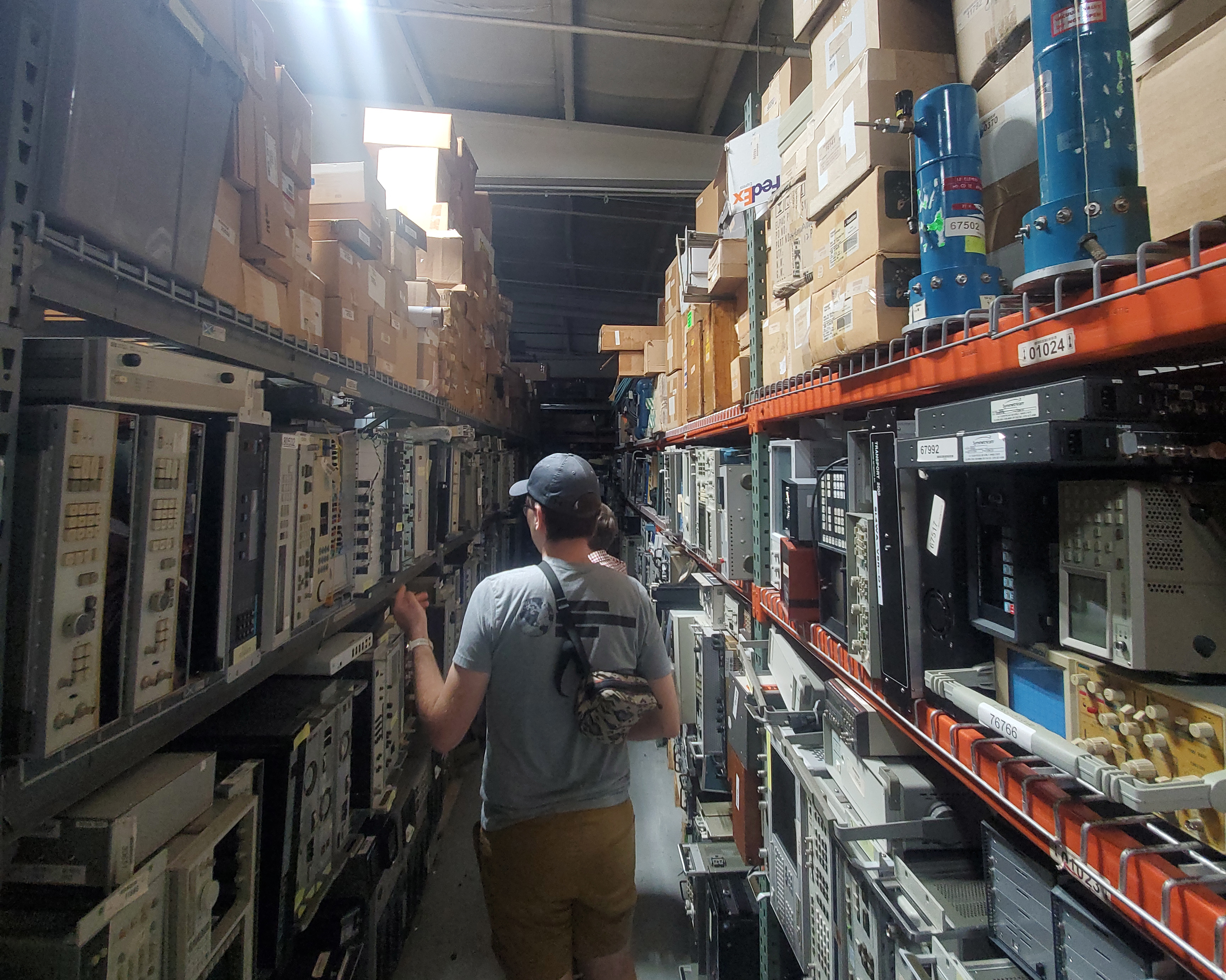
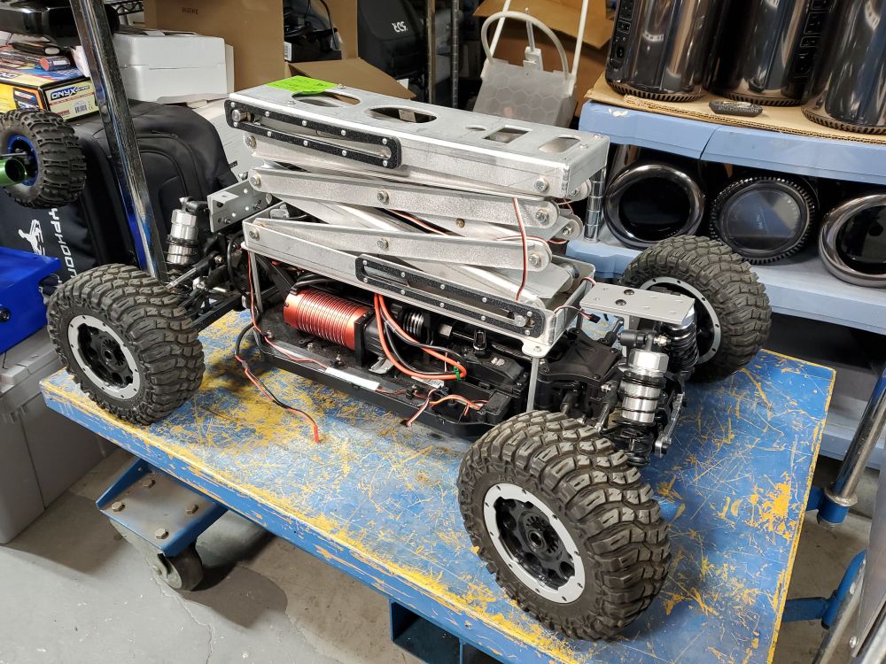
While the goal for this project is to get something working quickly, allocating space and planning accordingly for integrating some companion computation for automated tracking would be excellent. For the Pixhawk system, this means having enough space and mounting points for a single board computer for vision processing and or visual based obstacle avoidance. One of the best ways to have space going forward is to have an accurate mechanical model of the whole system, so keeping CAD up to date is a priority. Taking a look at the ChassisI picked up this from BMI surplus [link], during an adventure with Jake Hecla [link] and the mysterious Arsenio [link]. For some quick back-story, BMI surplus is this incredibly interesting surplus emporium in Massachusetts, while they do not have tours, you can pick up items that you purchase ahead of time. We were fortunate to get some time to browse inside the incredibly dense arrays of machines, gadgets and gizmos. A lot of this stuff appears to come from Lincoln Laboratory, the friendly neighborhood spooks. I was able to haggle a bit and purchased the mystery RC chassis for ~50 USD + tax, along with some other items. 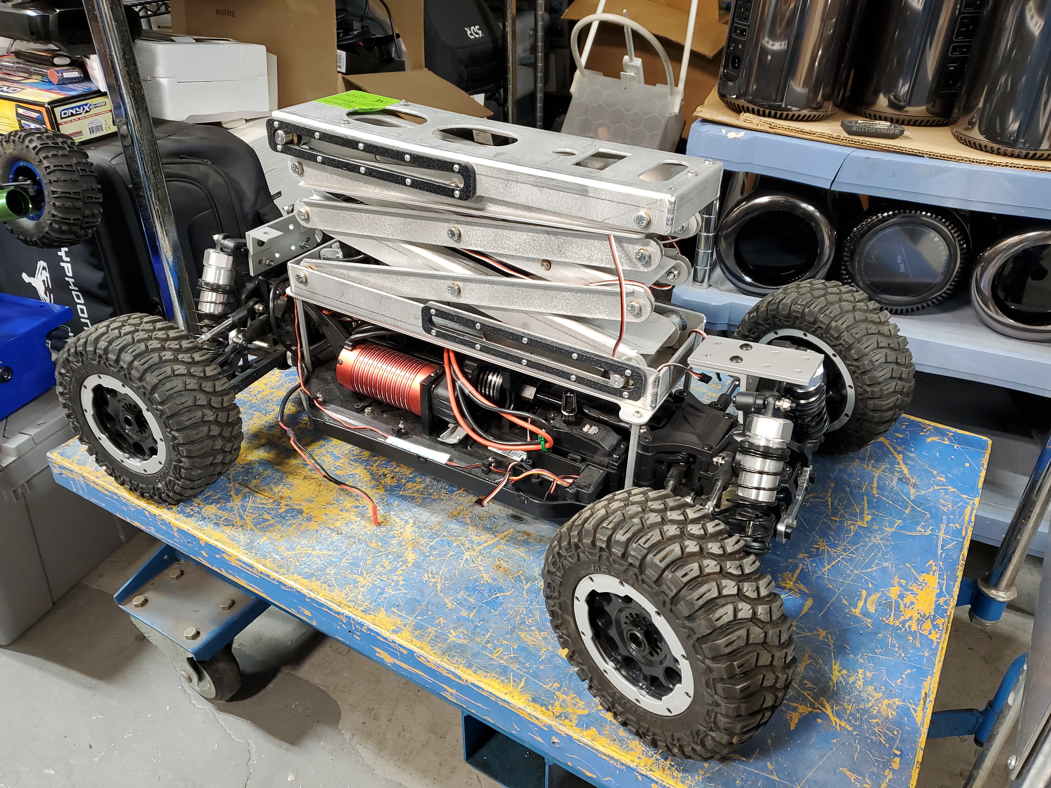
There was no actual information about this thing, what it was used for, why it had a bizarre Z-Axis linear actuator bolted to the top. I did some digging but was unable to find any write-ups, technical papers or anything about this 'thing'. Maybe they were surveying, maybe it was a mobile device to take images at the door height of a car? No idea Fortunately the actuator was a simple DC brushed motor linear actuator, which was easy to control. Behold a scaled dolly shot of this contraption in-action. While this thing was interesting, there was no way that I was going to even try putting a full sized camera gimbal on this thing, so after a few screws the Z-Axis was removed, underneath we see a water-jet plate on, the most comically dubious 4-40 standoffs I have ever seen. 4 inch long 4-40 stand-offs is wild. 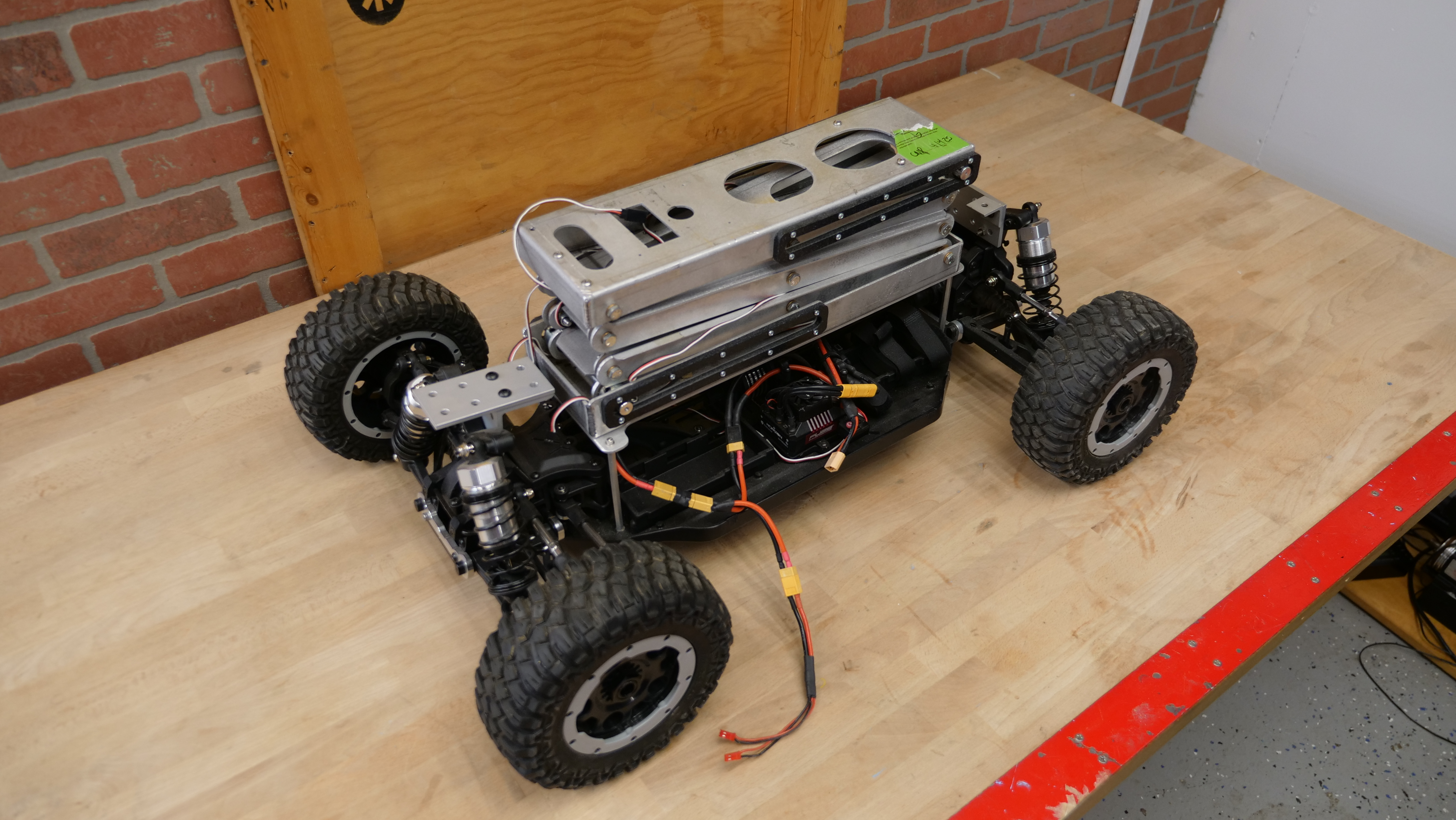
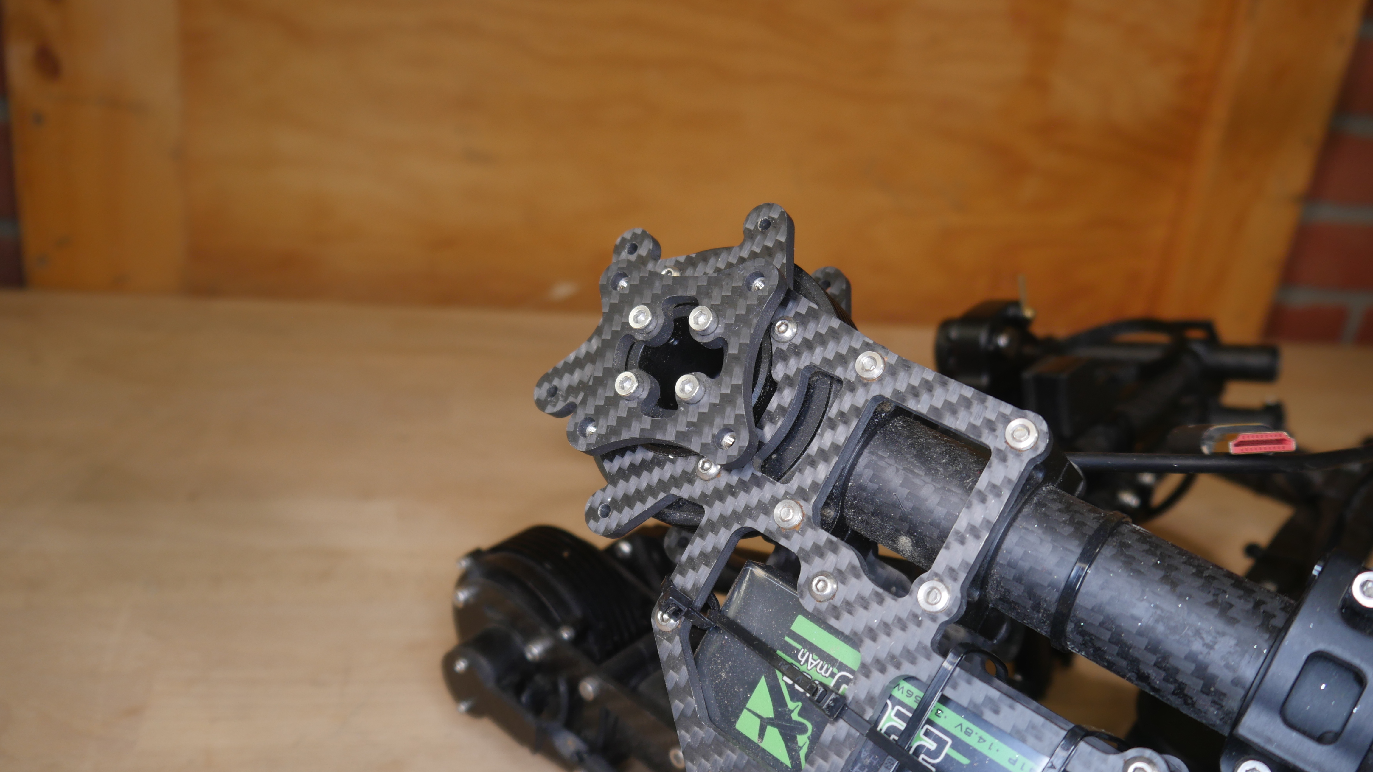
Hardware Mock UpFor the purposes of determining what this could look like, and if it was going to be too unwieldy, I opted to temporarily use the existing mounting plate, make a 3D printed adapter and get a hint as to what I'd be working with. First up was to remove the handle assembly that's native to the Movi M10, which inherently flips this whole gimbal upside-down. I was somewhat concerned with how much loading would now be on these four M3 screws, but that's something that future-Dane needs to resolve. Shown below is the gimbal, with the mount point shown. Likely, going forward I would probably end up picking up the central 4 screws and try and mechanically provide some additional support. 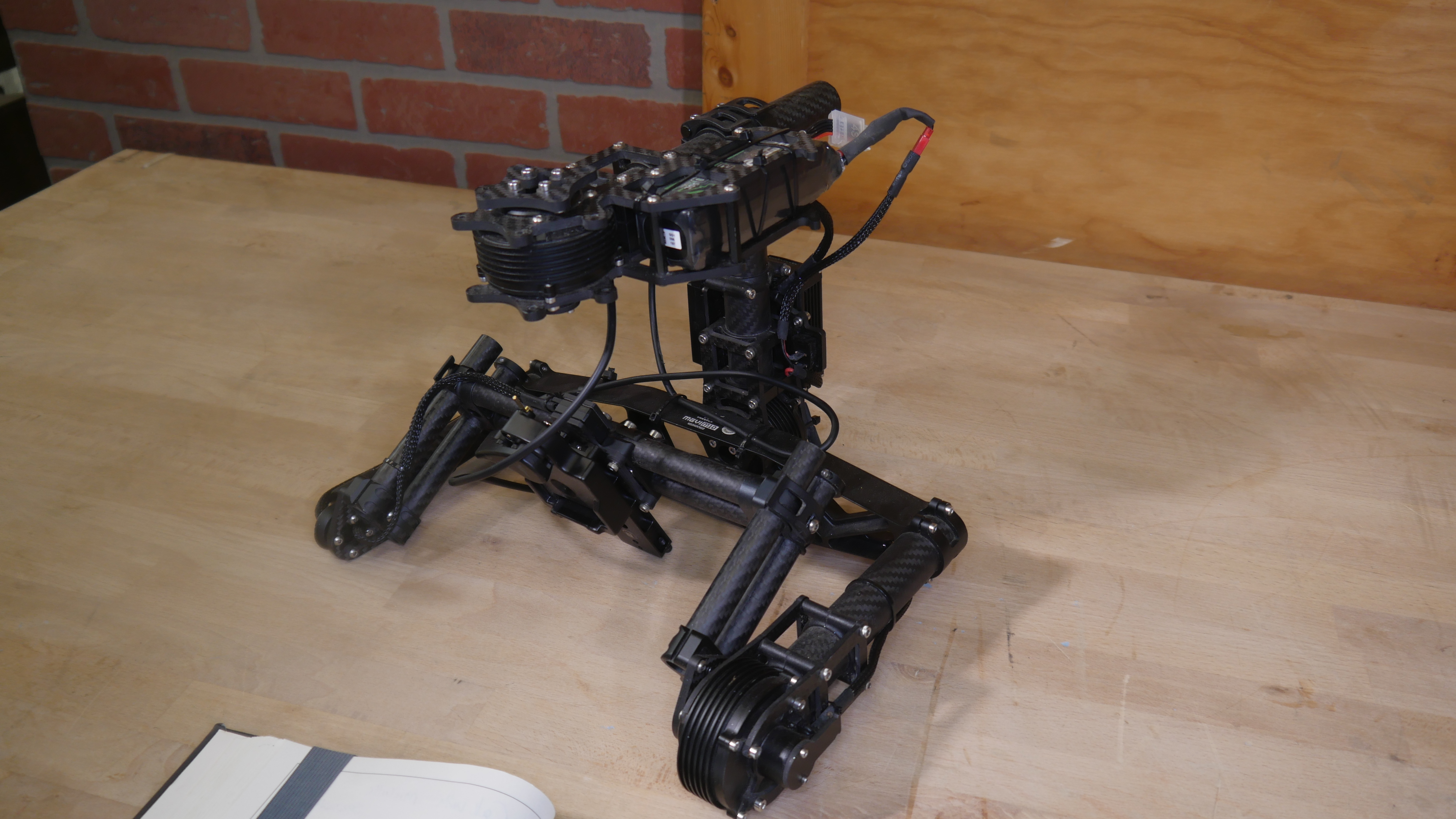
I used some quick thermal inserts to pick up on the long flat portions of the existing chassis. By using flat-head screws, I can take up a bit of tolerance mismatch, and when loose it can slide back and forward down the top platform. This print was a placeholder, but it did let me get a good visual of how tall this whole stack-up would be. 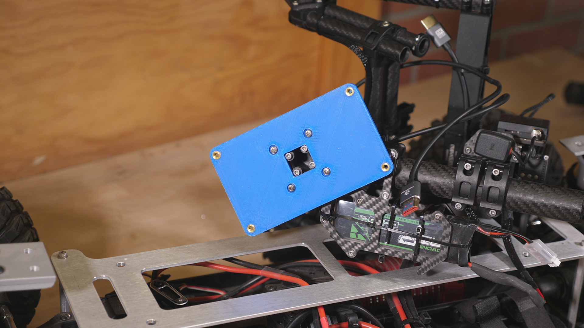
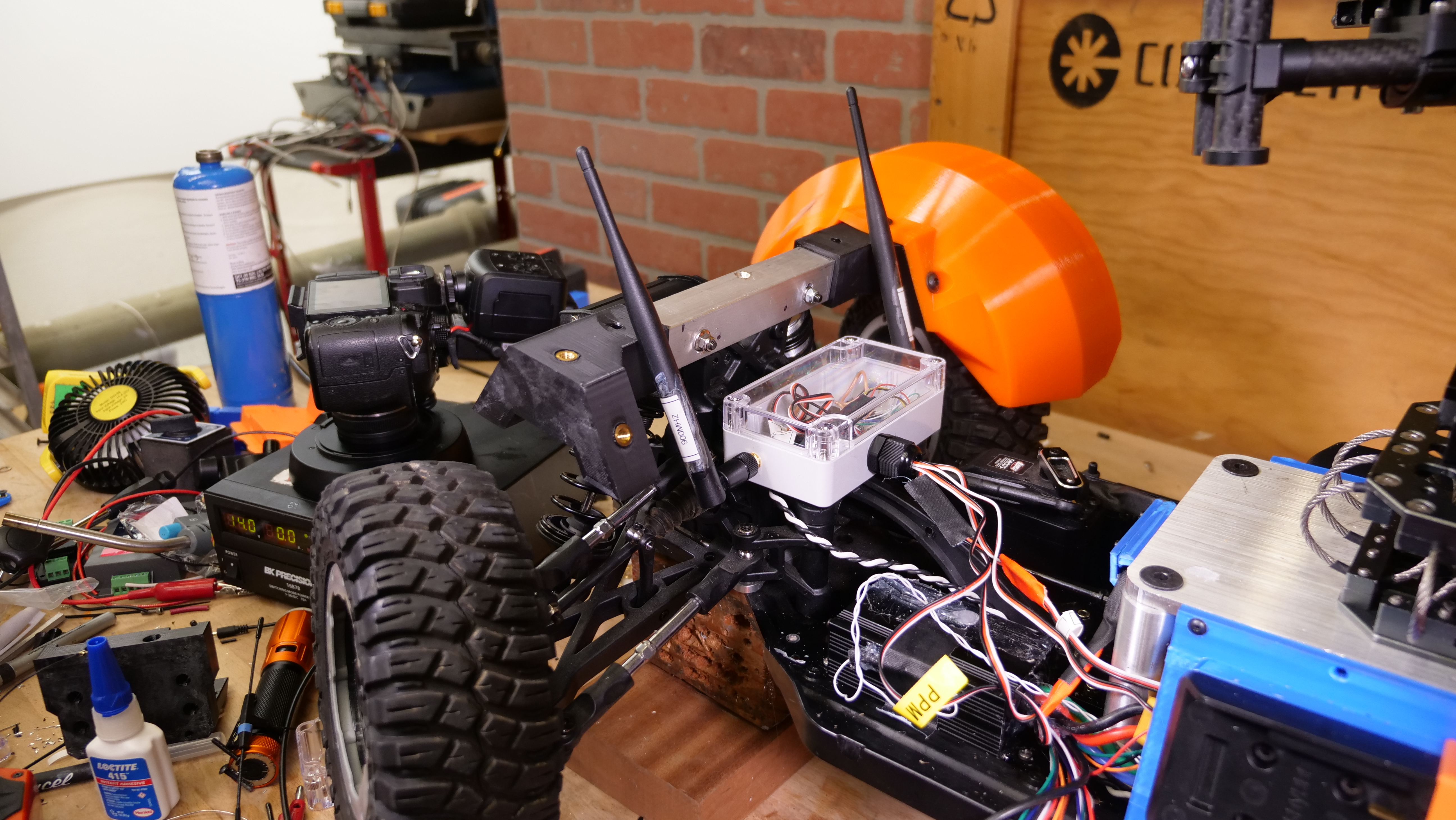
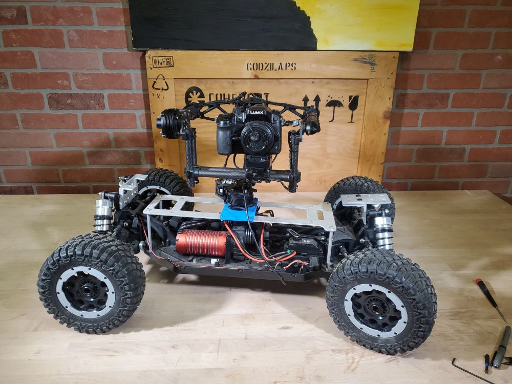
Finally, the first test fit to see what the gimbal looked like on the chassis. While this is a quick mock up it did provide some insight as to how quickly the height of the whole assembly could easily creep up if it wasn't actively being constrained. The lower the camera and assembly height, the lower the effective vehicle center of gravity remains, increasing its stability while helping reduce rollover forces. Making a mock-up may take time but it really lets you skip an iteration step as instead of an ill-defined cad model you now have something to interact with on the lab bench. It is huge. I took the opportunity to also do some placement tests for where the battery mounts could end up. As it was fairly apparent, using batteries as bumpers is not a great plan. The two packs would likely need to lay as low as possible but still remain accessible for hot-swapping two packs at a time. The only reasonable spot would be along the sides, while not interfering with the gimbal or the ground clearance. 
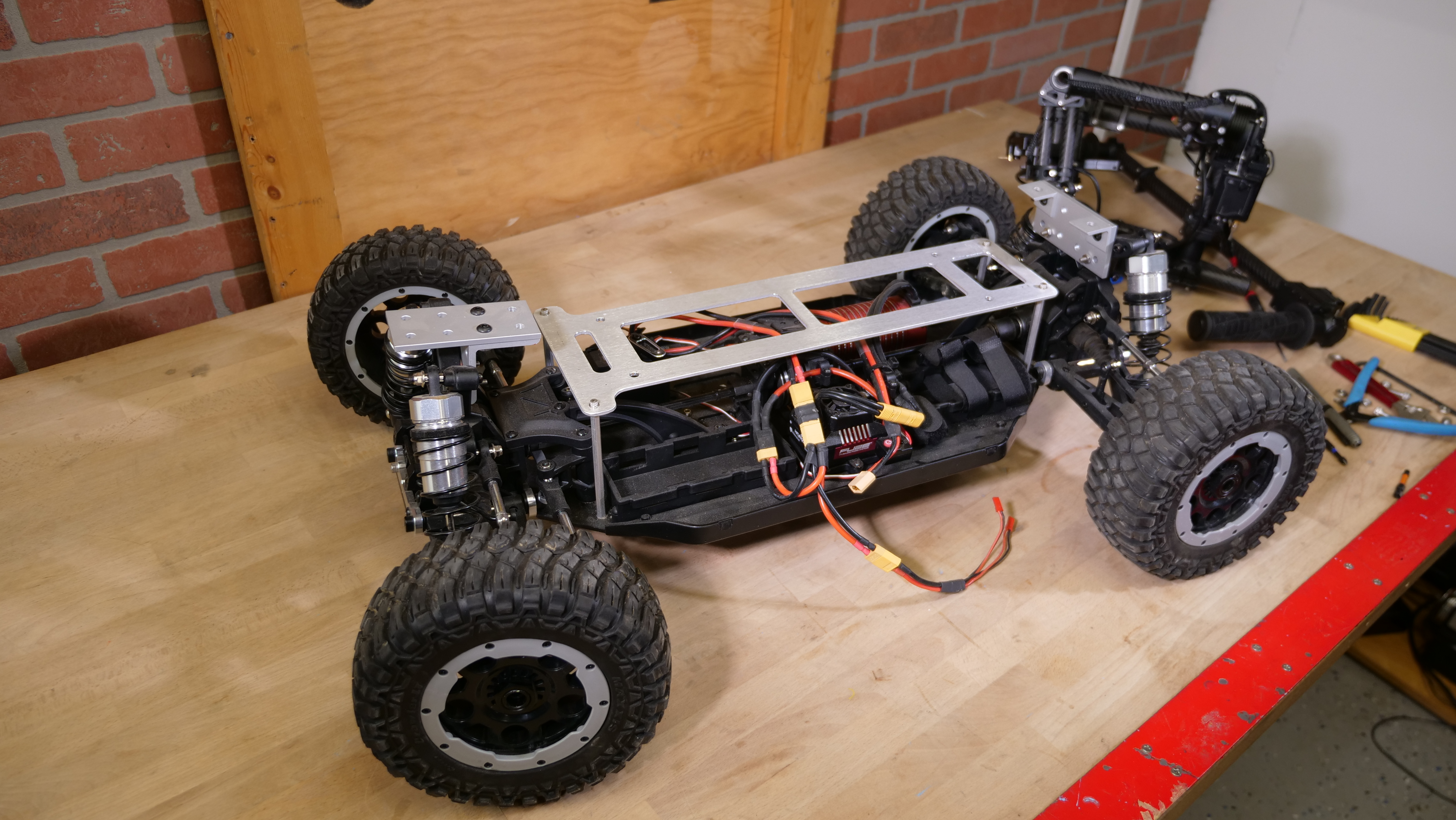
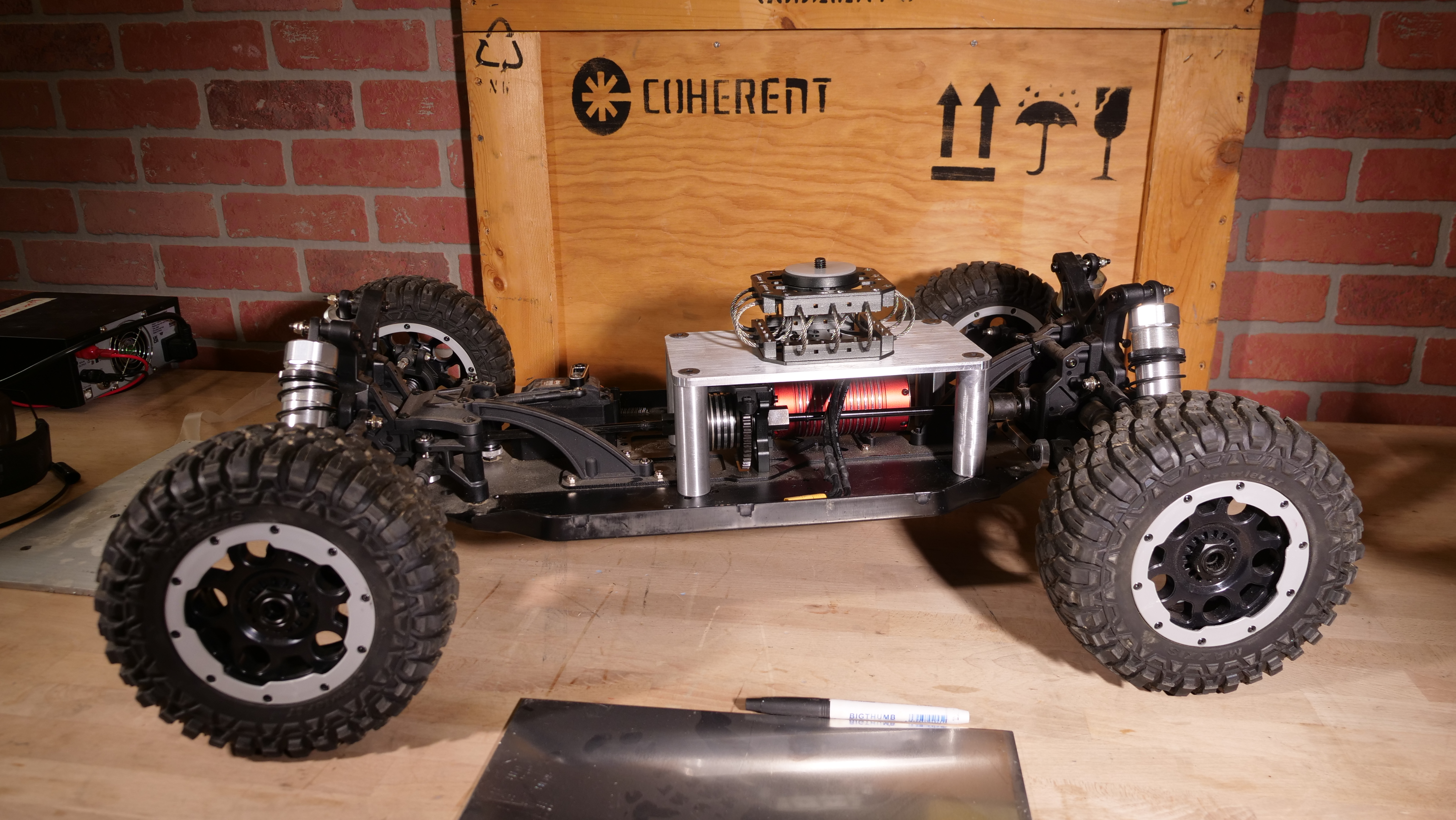
New MechanicalsA more structural gimbal mountThe floppy aluminum mounted on some adorable 4-40 standoffs was not going to do it, I needed something much more structural. While the gimbal itself is not mechanically heavy, its mount point does need to be as low as possible to help mitigate flipping. Ideally the Gimbal-camera assembly is remove-able from the frame, such that i can test and tweak the motor control tuning, fenders and the like without putting everything else through hell. Time to fire up the CNC, turn some proper standoffs and rigidly connect to the frame. The basic plot is to provide a solid foundation as close as mechanically possible to the frame for the gimbal and shock mount. Fortunately the sub-frame base plate is made of aluminum. I'm going to again opt for stand-off's to elevate the platform above the drive motor, but just use some large round-stock to provide a secure mount. After some quick machining, drilling and tapping we have our new elevated gimbal platform, with countersunk M8 flat head screws. This intentionally barely clears the drive motor, and leaves the central round part of the spring damper mount recessed to keep the Z-offset height as low as possible. 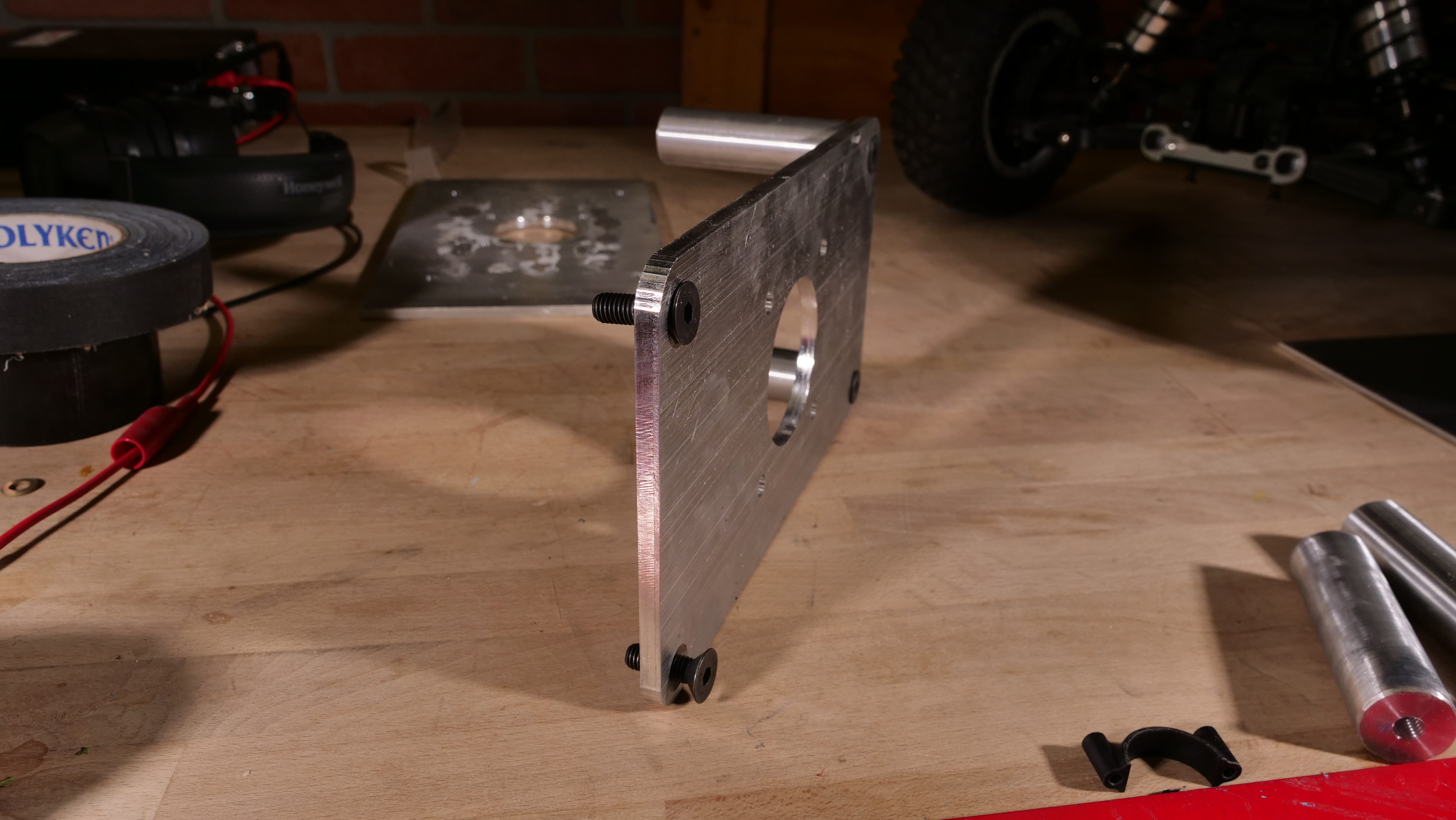
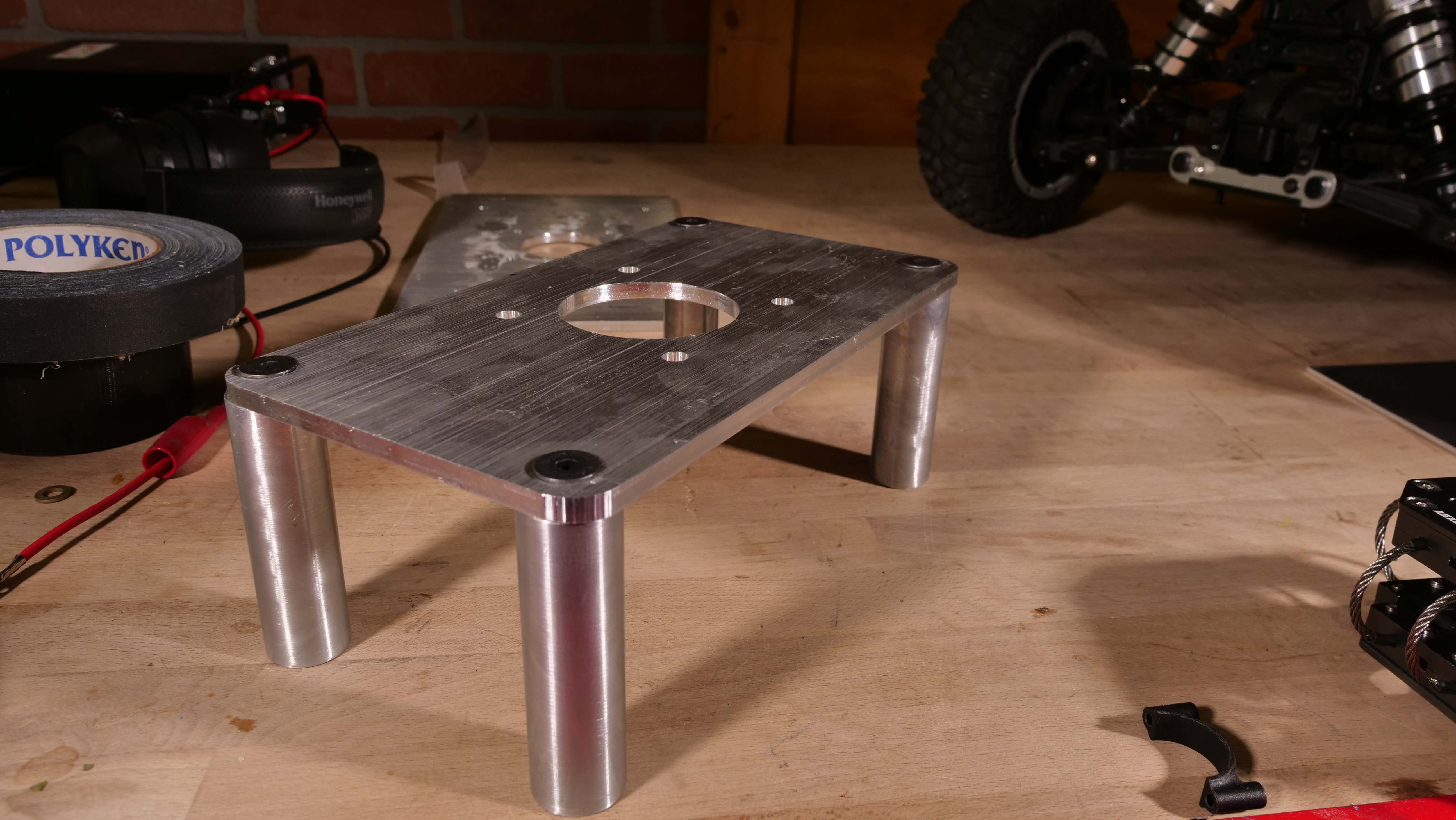
The spacing of the standoffs is nominally tied to the closest positions that I could pick up that were co-planar without bumping into the motor mount / servo mounts. While this is slightly aft of center, it does permit space for the somewhat heavy batteries to live, ideally resulting in the total mass balance towards the center. 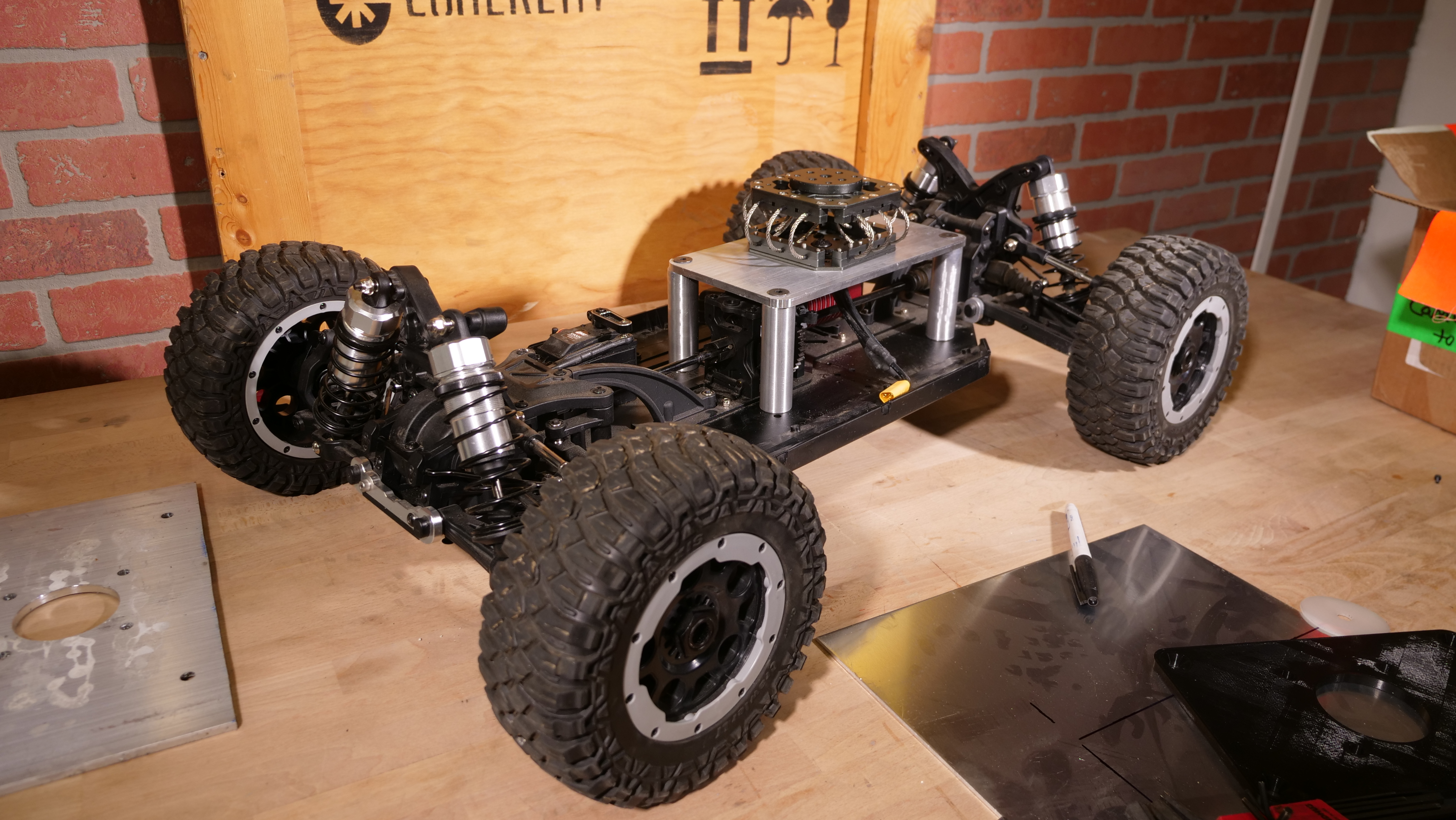
After verifying location a few times, I punched some holes through the chassis and used some M8 screws with flanges to firmly attach the new platform to the chassis. These were initially just tightened to a few newton meters, but on the final assembly did receive some mild loctite to help with vibration induced loss of tension. Fenders for Ice RacingOne of the big issues with racing on a slushy surface is the slush getting everywhere . I do not have a traditional chassis for this vehicle, so it's up to me to figure out how to contain the slush, while not being too inflexible. This is a great option for 3D printed parts, as it's a lot of odd shapes and contours, however, this is also a battle bots crossover episodes , and oddly, flexible things should out-perform static things. Initially, for iterating and quick prototyping, the fenders are normal PLA. 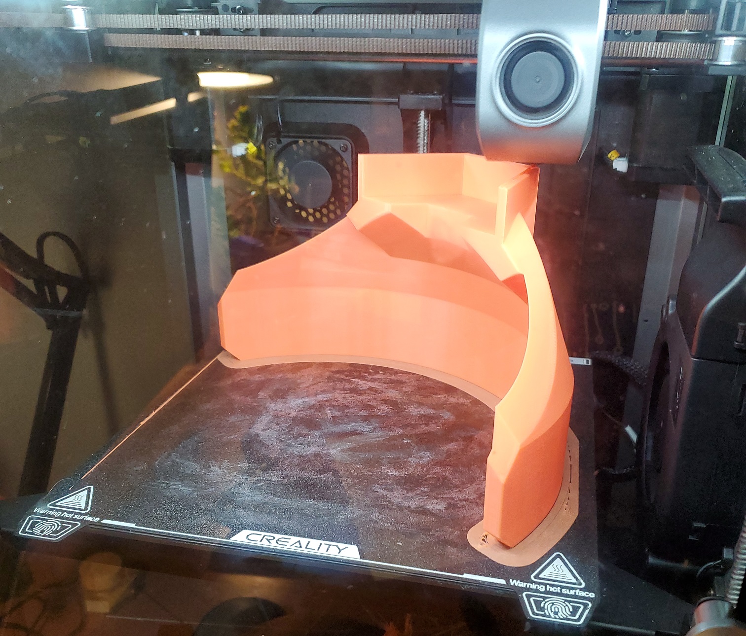
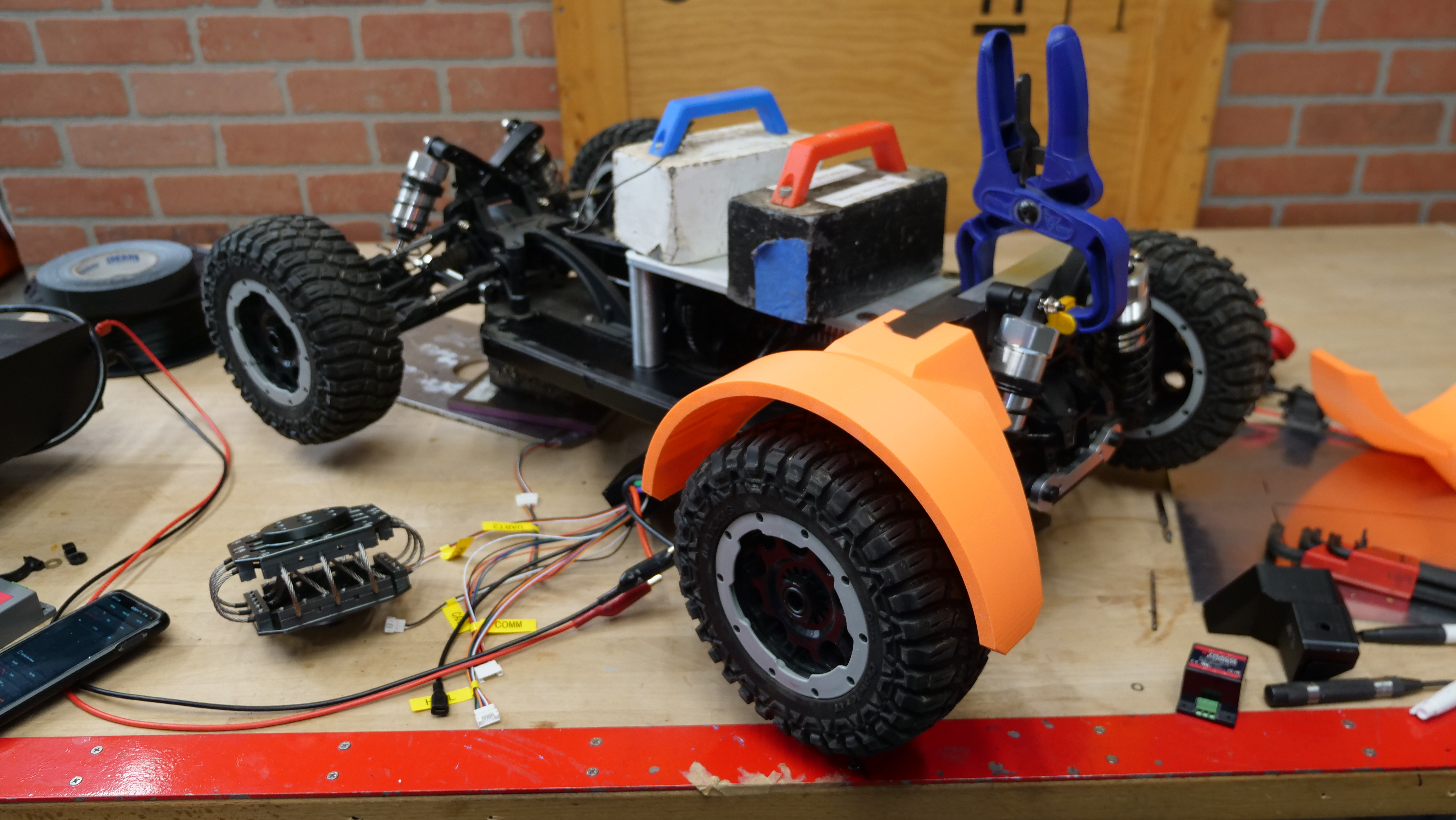
Comically, up to this point, I have never actually printed with commercial TPU, which is the go-to plastic flexible elastomer. I cant think of a better use case than fenders on a RC car frame. Just like a commuter-bike, the more of the wheel path that is covered, the less can get sprayed onto the camera and gimbal. The plot is to pickup a hard mount, which in this case is some aluminum angle stock, use a standard PLA part to provide a mounting point close to the wheel, and then transition into a TPU part around the wheel. I had initially tried 85A TPU and it was just a bit too fiddly to reliably print, without re-doing my filament spool holders to be lower resistance. Any resistance was causing under-extrusion and it was difficult to manage. I opted for switching to 95A filament, which is stiffer, and did a subsequent slow weekend print to make flexible tire fenders for the rear. The rear mounts are mirrored but both mate with three M6 threaded flange screws. After fiddling with settings to get a reliable print on the fenders, its a good idea to start planning a TPU front bumper to help keep this thing from getting smashed too easily. The print time for a single wheel fender was approaching a day and a half on a Prusa MK4. For this specific print, I opted for high wall count 25% infill, this should result in a fairly stiff part that's able to absorb impacts. 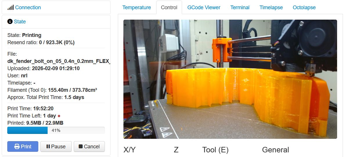
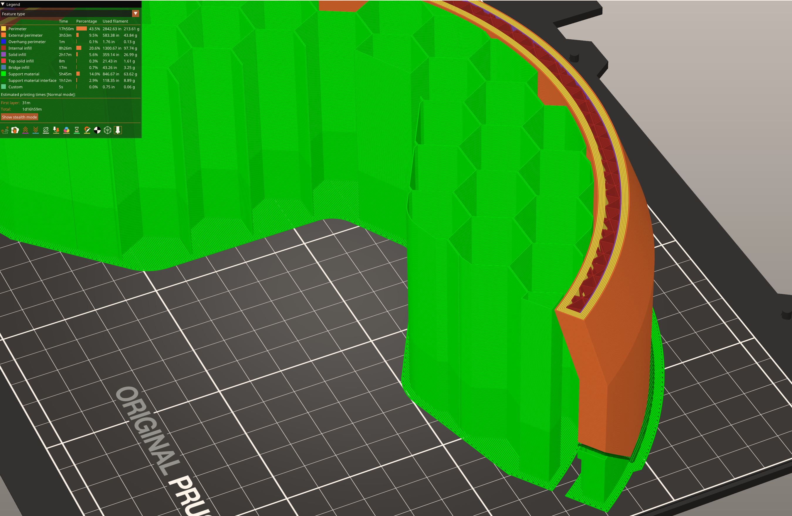
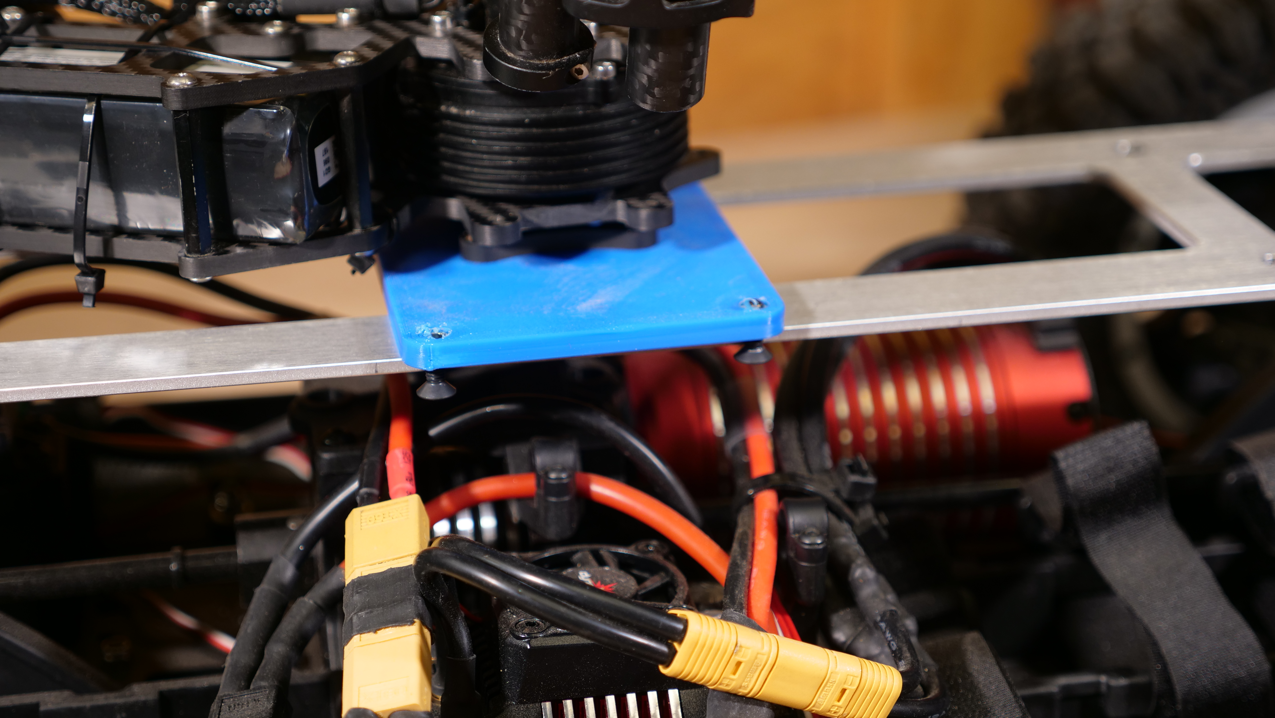
While it would have been ideal if all four fenders were the same part, the steering up front requires a lot more clearance, resulting in a larger radius. The printed part does pick up the same hard mount point I didn't mention how awkward removing the support material is for large TPU prints. Its time consuming just due to how impact and force absorbent it is. The layer-layer adhesion is amazing. Finally a spool up of the chassis on stand-off blocks, fueled by the two series DeWalt batteries. As I learned from a friend, full RPM in this situation is outside of the motor and drive-train specs, given that i was now running 10S / ~40v. The short blip of full speed was plenty to see how frightening this monster would become. To mount the side plates, i used a long tip marker to indicate where the print would align with the chassis and used a punch to transfer those locations so they could be subsequently tapped. With the holes in the gimbal riser tapped and the chassis clearance holes drilled, it's time to put everything together. Due to the right side of the vehicle's simplicity, I'm opting to install its cover plate first, there's only two wires to worry about. Time to put the electric screwdriver to work. Six M3 screws grab the aluminum top-plate and six subsequent M3 screws attach the bottom of the print to the frame. This video has audio: Click to un-mute Battery MountsBoth sides of the gimbal mounting plate fit in separate, blue, printed plates that hold the main power switch, pre-charge and battery mount points. The prints pick up tapped M3 holes above and contain M3 thermal inserts below to pickup screws from the chassis. The printed mounts then mate to an off the shelf, injection molded DeWalt Battery terminal, connecting with four M4 screws. With the battery latched in, it is surprisingly abuse tolerant. Shown below is a standard DeWalt 6AH 20V battery module. The orange cover captures any exposed wiring present from the battery adapter. Ideally the gap-space gets covered up to help mitigate ice slush ingress, but that's a problem for future Dane. For the left side of the chassis cover we have a lot more going on. The main power switch, pre-charge and pack voltage indication is present, with associated wiring on the backside. Behind this are the dc/dc converters that provide steering power and indication light power, along with our remote controlled relay for headlights / tail lights. 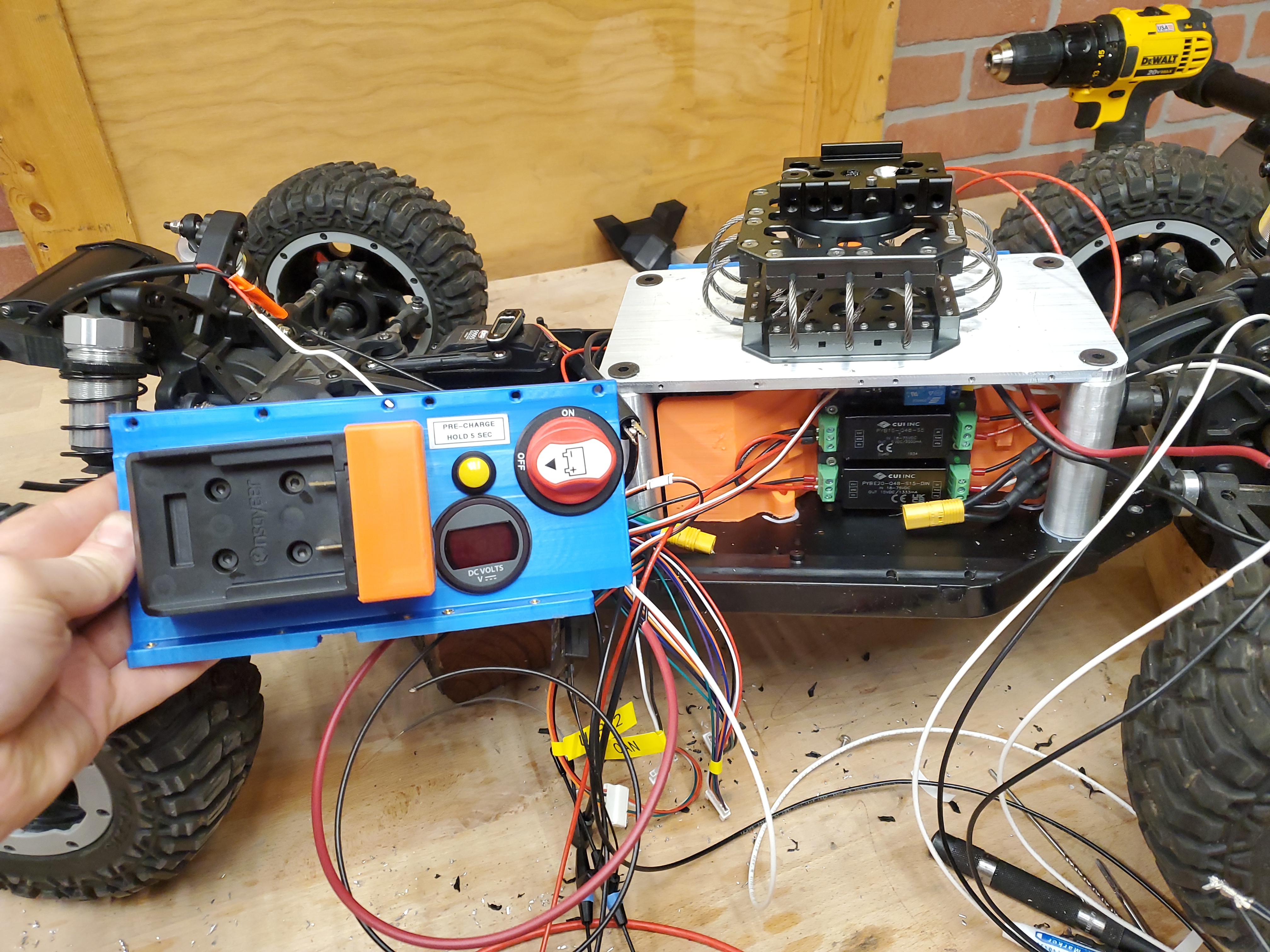
"Headlights and Tail lights"Having some visual indication on this contraption is helpful, especially with how quickly dusk appears. A small headlight and rear facing red lights should be a quick addition: For a headlight i opted for this waterproof small module, intended as a 3rd party automotive light. It fortunately takes a wide range of operating voltages so i can put to use a 15W dc/dc module that's been collecting dust. For the tail lights I'm also opting to re-use some 12V indicators purchased for a project from ages ago. While they are not incredibly bright they are visible from a reasonable distance. We do have a number of channels available on this radio, including switches. Having the ability to disable lighting, if it were interfering with the camera or causing reflections, would be useful, especially remotely. To implement this I'm opting to go simple, a very basic RC controlled relay. With the simple 3d printed brackets installed, I was pretty happy with how things turned out. Sorting out HD FPVThere's really four options for long range video links at the moment, low resolution low latency analog, high definition high price DJI hardware, previous generation niche cinema hardware and Open Source Build the whole thing solutions. As of writing this, the FCC has banned most of DJI's hardware offerings [Link]. Given that present-generation DJI hardware is not banned, but future generations are, the prices have become quite high. For reference, the transmitter alone is 1100 USD. We want something equivalent that hits all three ideals: low latency, high resolution and 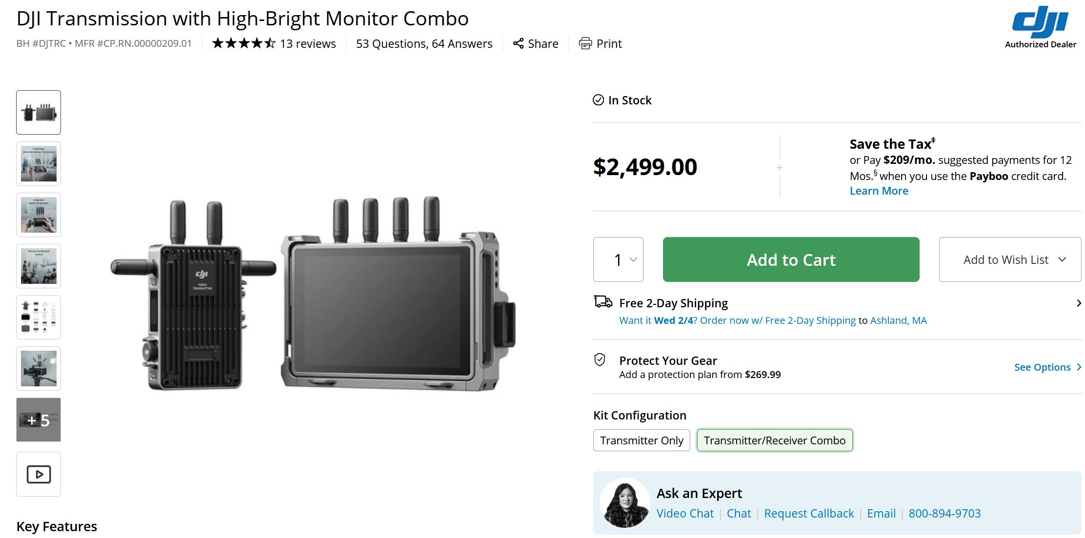
Let's look at the niche cinema hardware of yesteryear and see if any gadgets are available for low ruble. Enter the CONNEX by AmimonThis gadget was released in 2015, roughly a decade ago, but the specs are really remarkable, especially for the time. 1KM of range? -10C operating rating? Not mechanically enormous? sounds great! 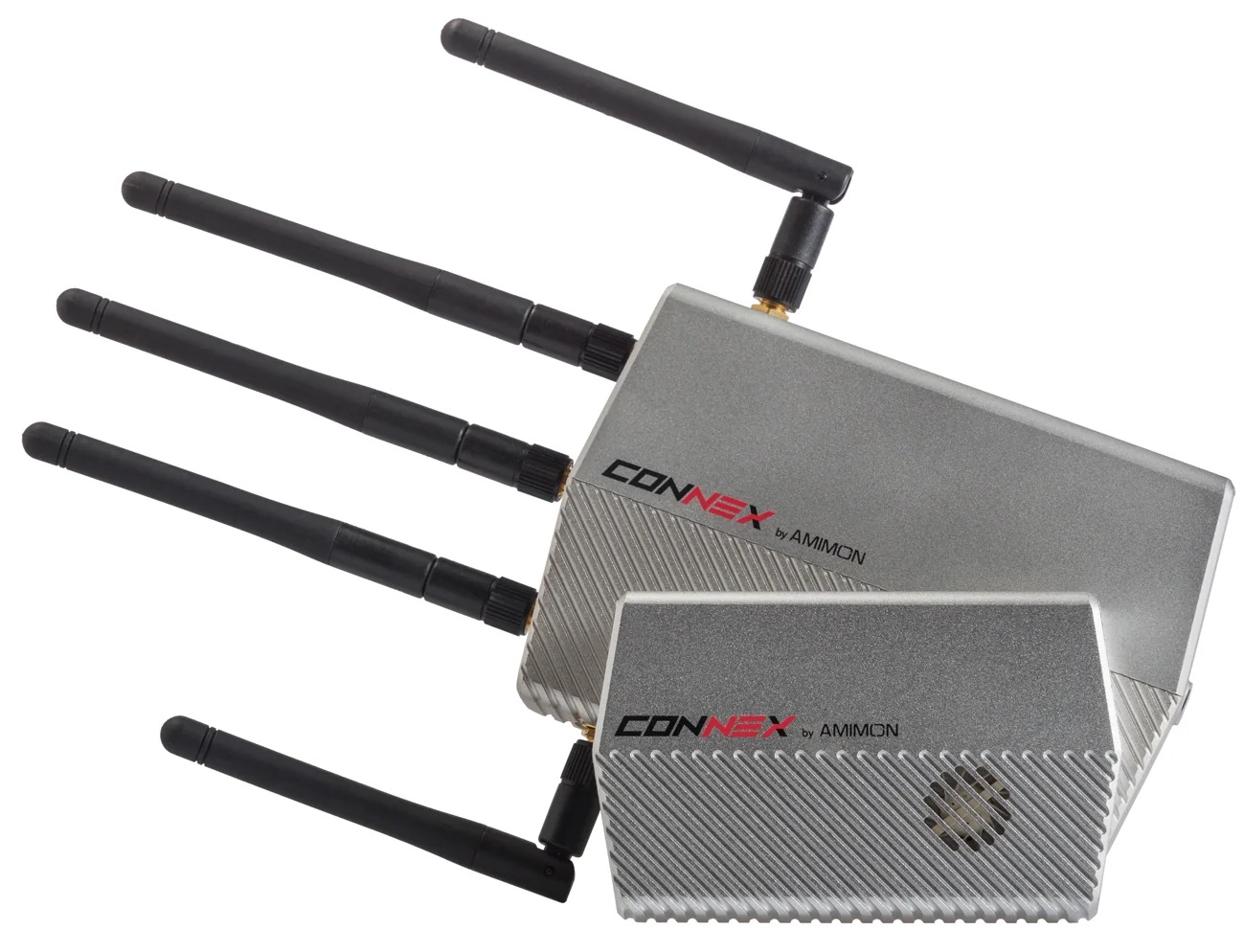
Here's a quick overview of the features direct from the manual. 1KM / 0.6 mile range is fantastic for that resolution & latency, and 5.8ghz antenna hardware is now fairly easy to come by. Given that we don't really know the orientation of the rover in relation to the pilot, we're stuck with omni antennas on the rover. The rover, unlike a quadrotor drone, is also physically on the ground, with the antennas barely 40 cm from the surface. Real world tests will likely net a shorter range but this is already an excellent start. 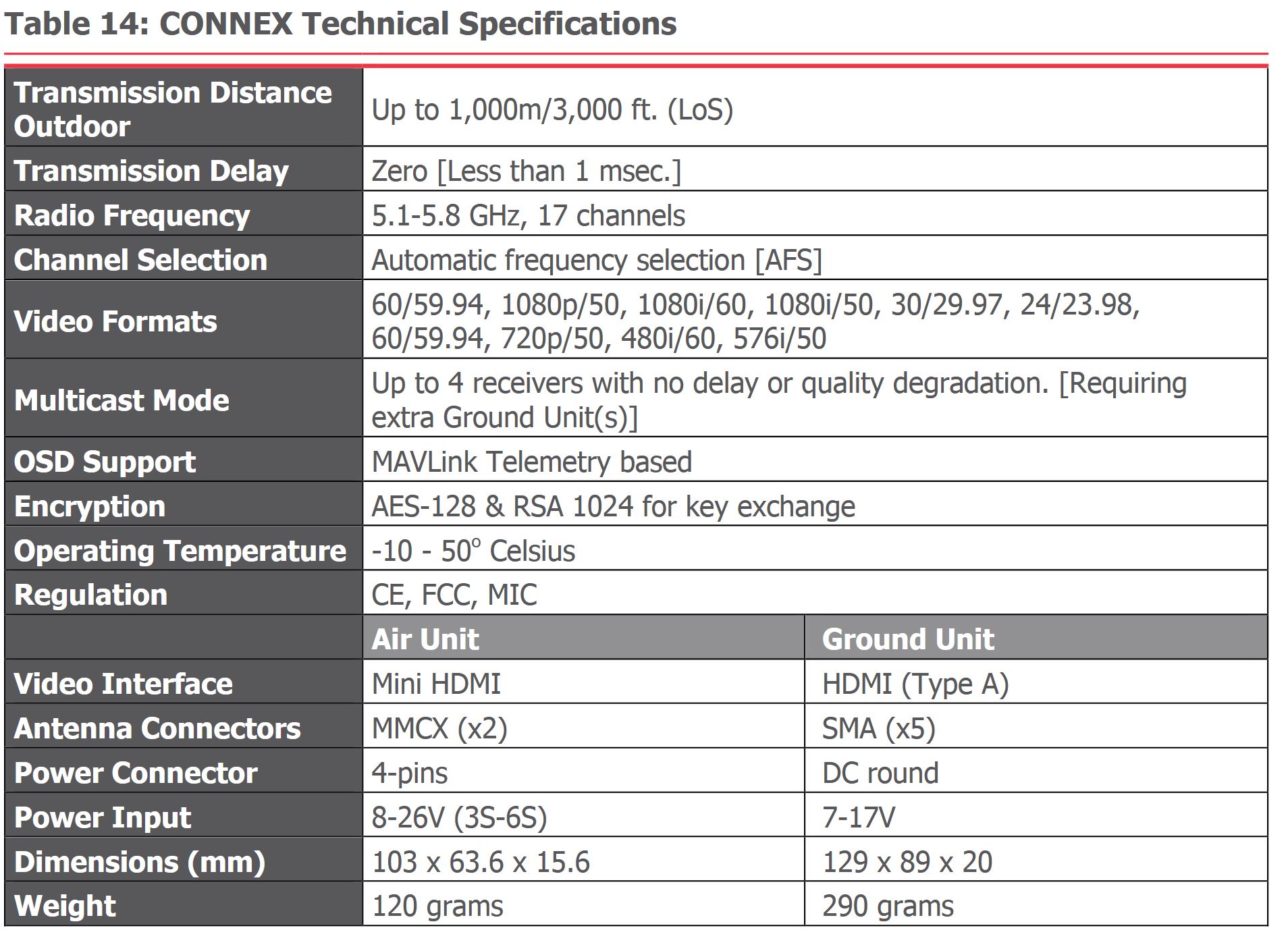
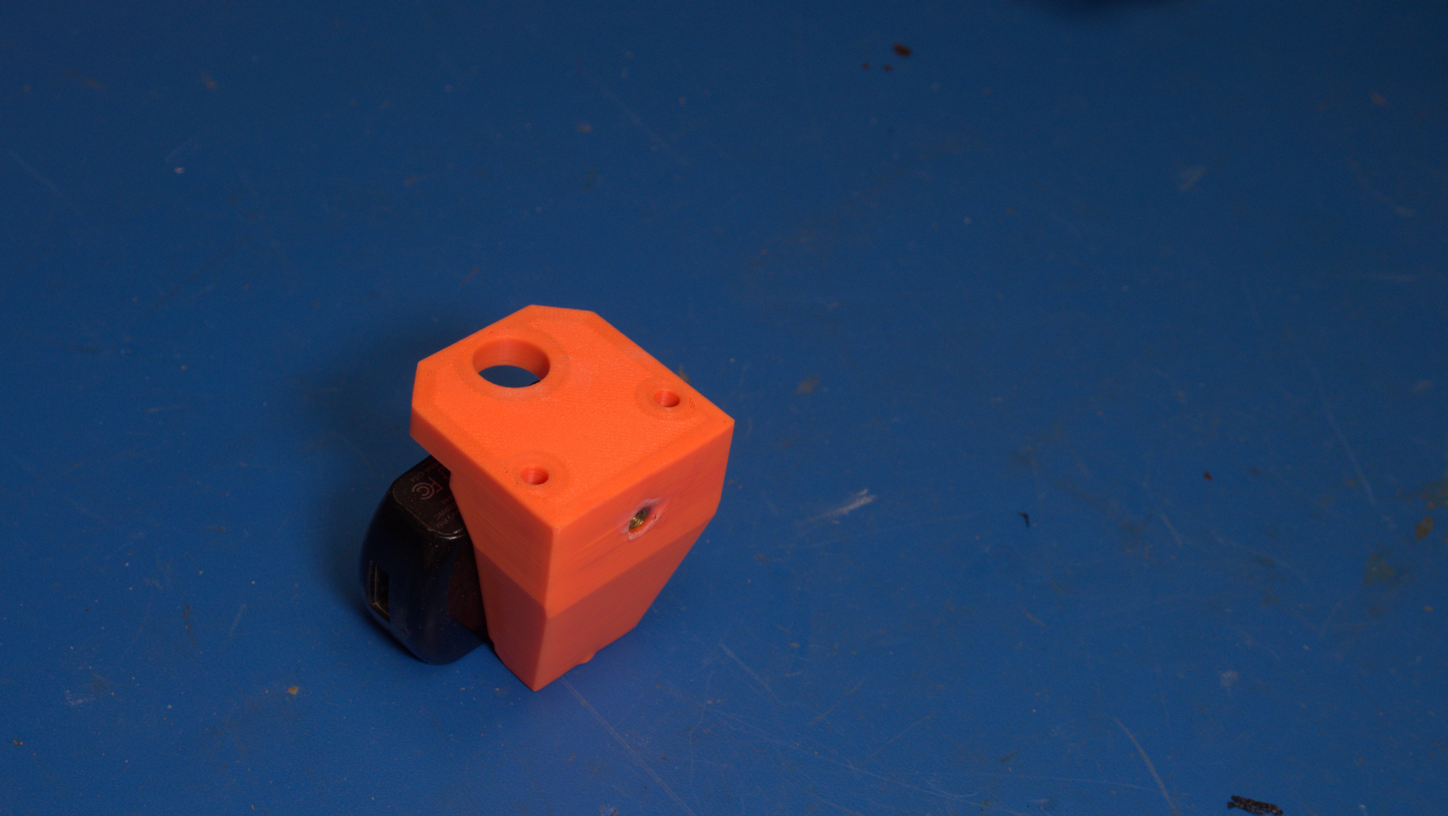
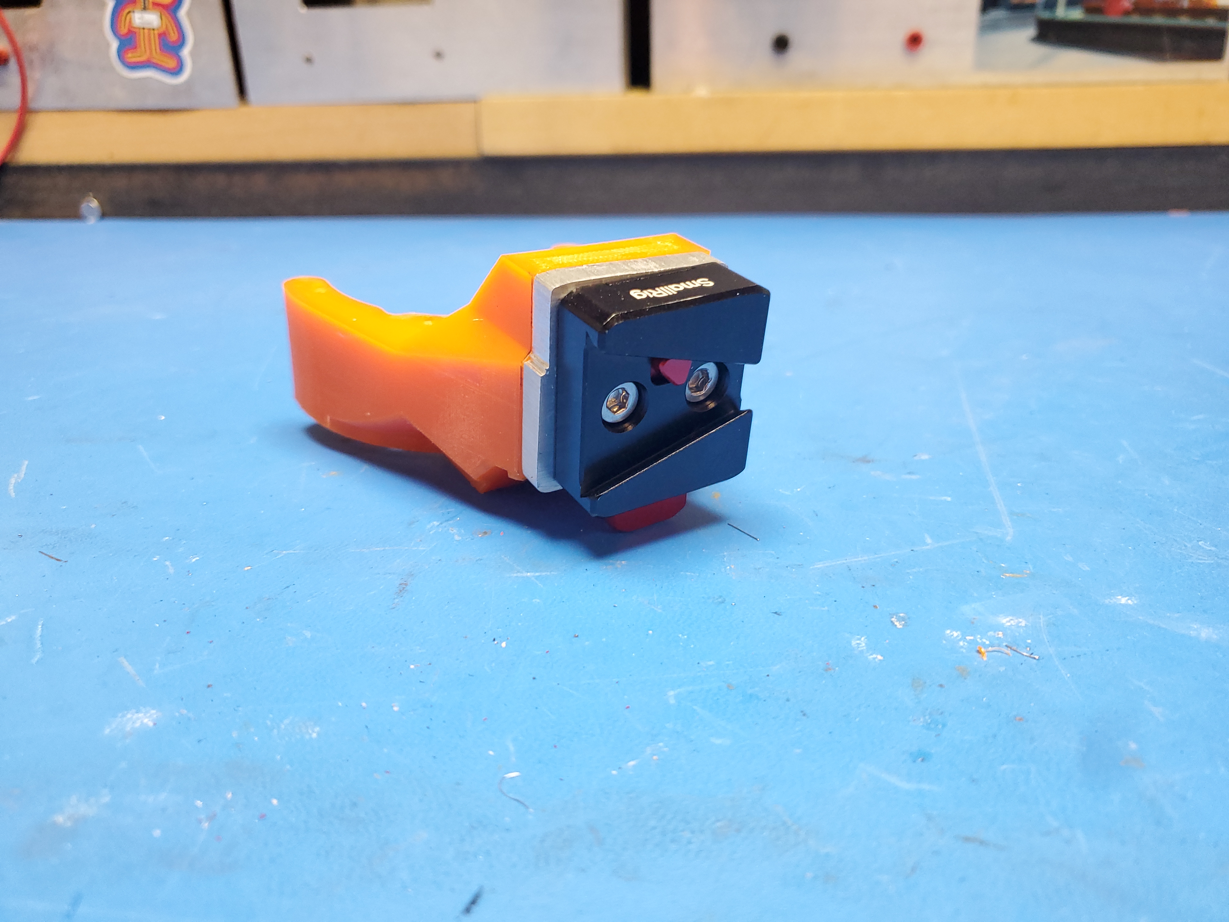
This is pretty excellent, and they do appear for ~100-200$ used on eBay, but Wait, why have I never heard of these things? Amimon was purchased by Teradek, who makes a very similar item just for 5X the price. Awesome. I purchased a set of transmitter and ground station radios from eBay and got to work sorting out how I would integrate them to this vehicle. One of the dangers of working with "older" hardware is not the hardware it's the support software. Narrators voice "there were software issues" The specs are quite impressive on paper, specifically the <1ms latency . I was also impressed by the -10 Celsius rating. On the rover side of the fence we need to pipe Mini HDMI from the camera into the "Air Unit" along with ~14V from the Gimbal battery. A copy of the manual for the Connex Amimon is available here [link], with a local copy here [link] Lets build a display and FPV receiver mountMonitors for outdoor use can be a bit tricky, you are inherently trying to beat the sun. I have been a fairly big fan of Liliput and opted for their 7" 1800 nit monitor, it supports 1080P and is covered in 1/4-20 mount points. They just work, have a wide input voltage range, and are so much more rugged than mystery 4-character amazon brands. The Connex receiver is somewhat large and the antennas do need to be facing upwards, so let's stick the whole thing on the back of the Liliput monitor. There are four M2 threaded holes on the backside of the Connex receiver, so our part will pick up the sides of the Liliput and provide a place for four screws to mate to the receiver, hugging the back of the monitor. Fortunately, all the input/outputs of the receiver are on the sides, so as long as we properly mechanically constrain the cabling we should have a pretty excellent little setup. 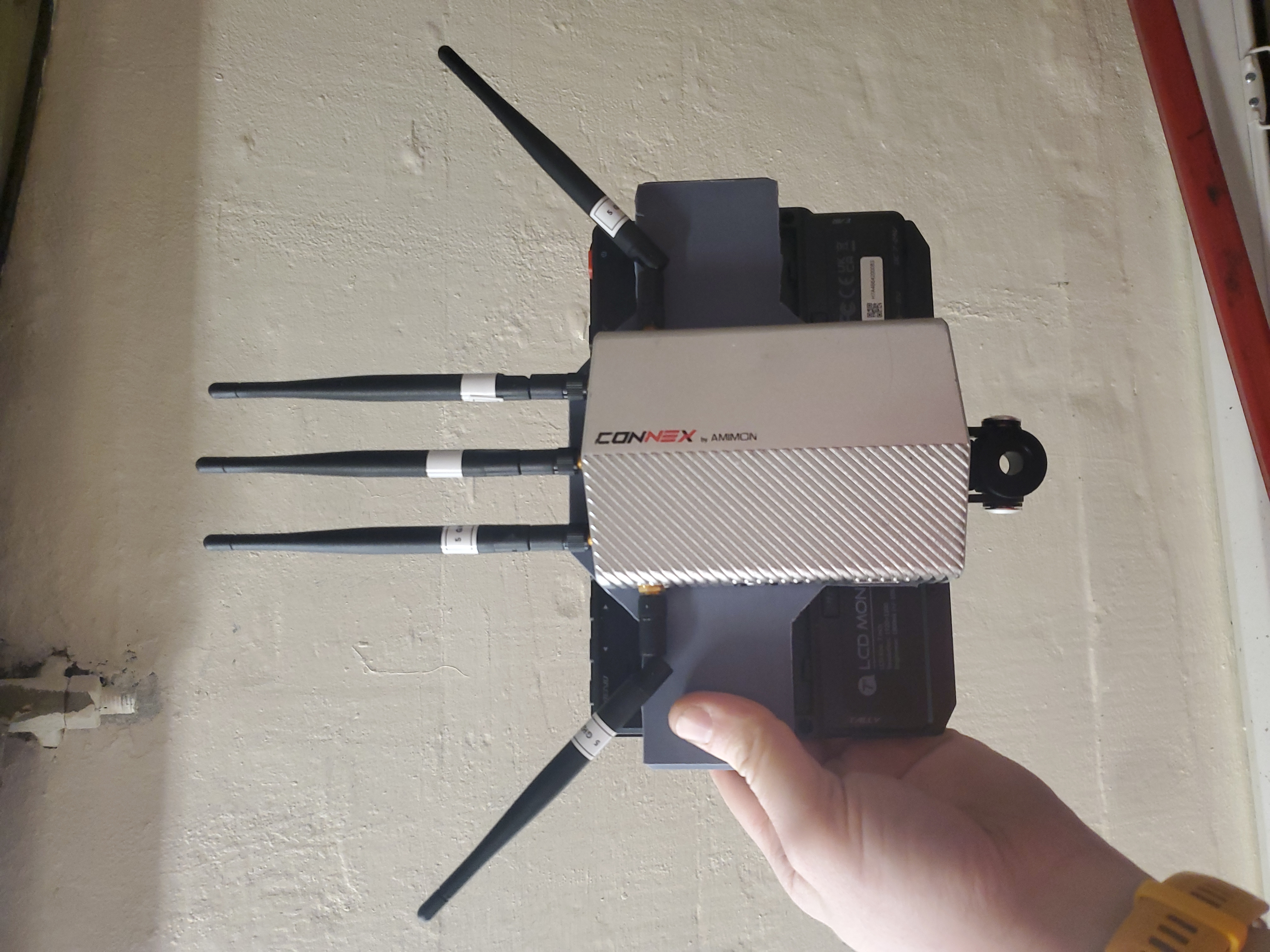
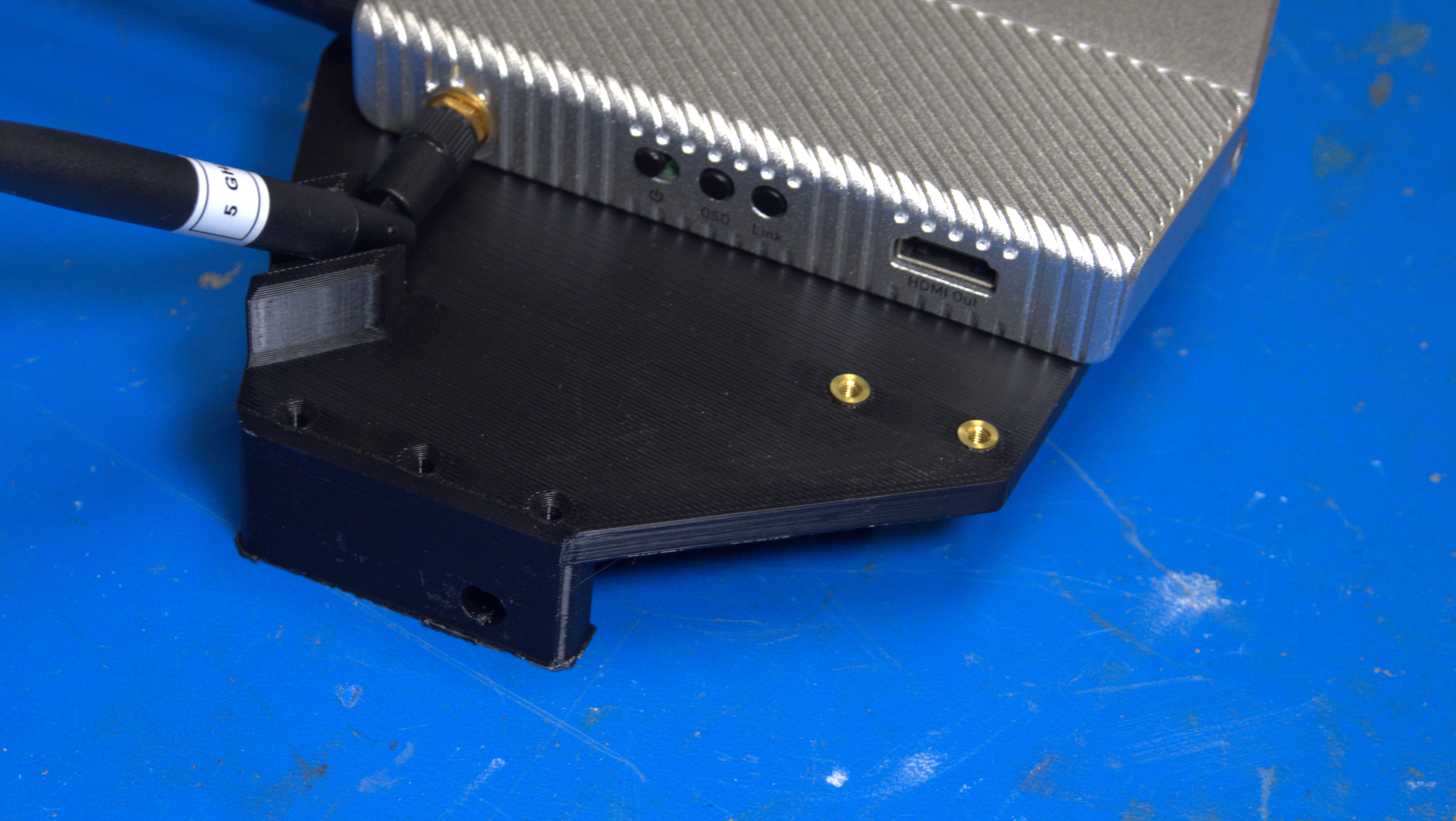
After some iteration and fit-testing, I came up with a slightly more mechanically robust part, using some epoxied in M3 screws to act as mechanical stiffeners on the parts that connect to the side of the monitor. M3 threaded inserts provide spots to help constrain the HDMI and power cables, while keeping the path to the switch and link connectors accessible. 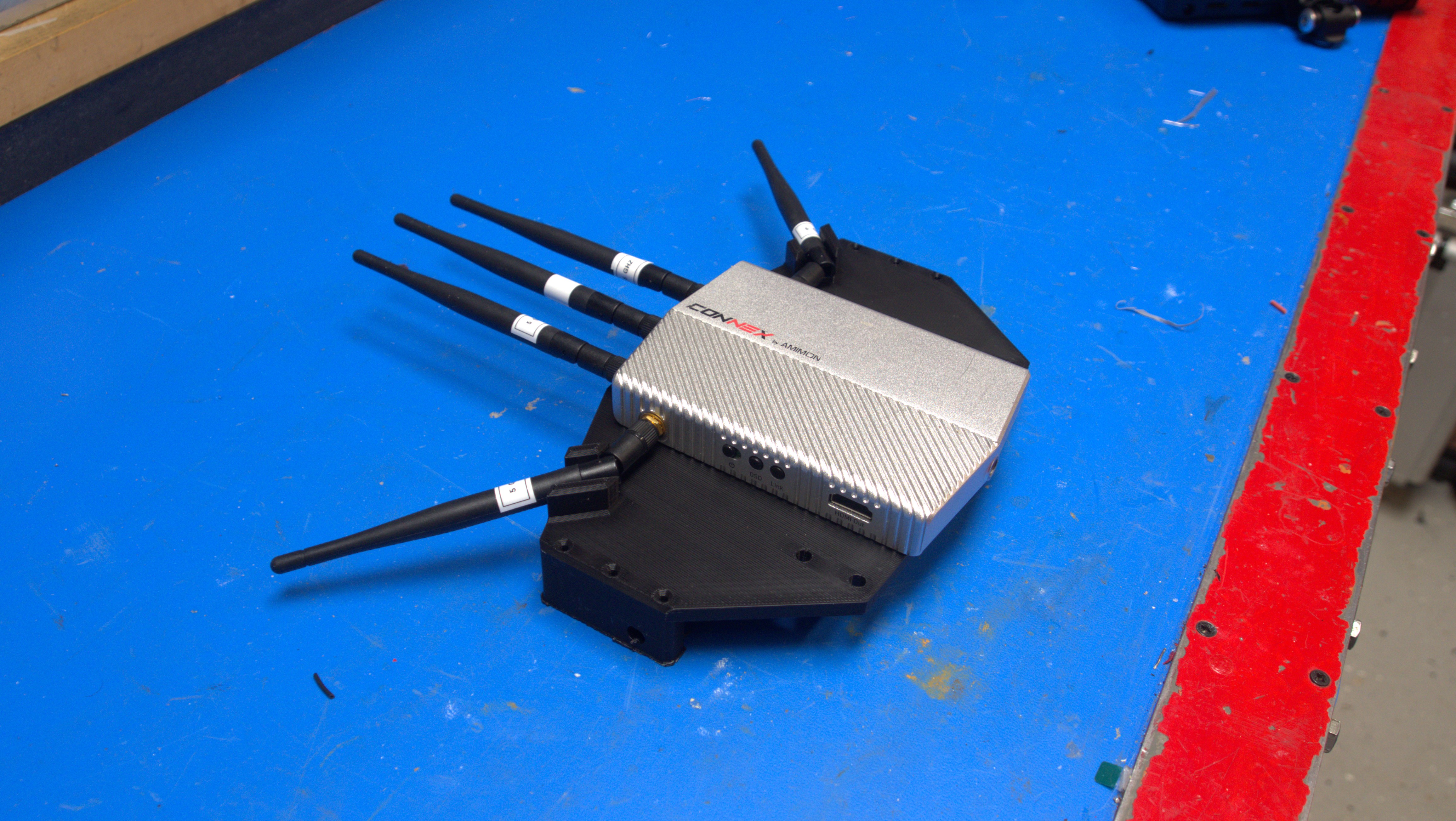
Now that we have a monitor and receiver for the handheld controls portion of this project. For the radio, I'm opting to use a Taranis X7, mostly because I picked one up at Guardian from the leftover cruft pile. I'm a big fan of the X7, I used it for SnowBot [link]. My only qualm is that there are no places to mount external gadgets or gizmos, if this had some M6 or 1/4-20 threaded mount points it would be excellent. 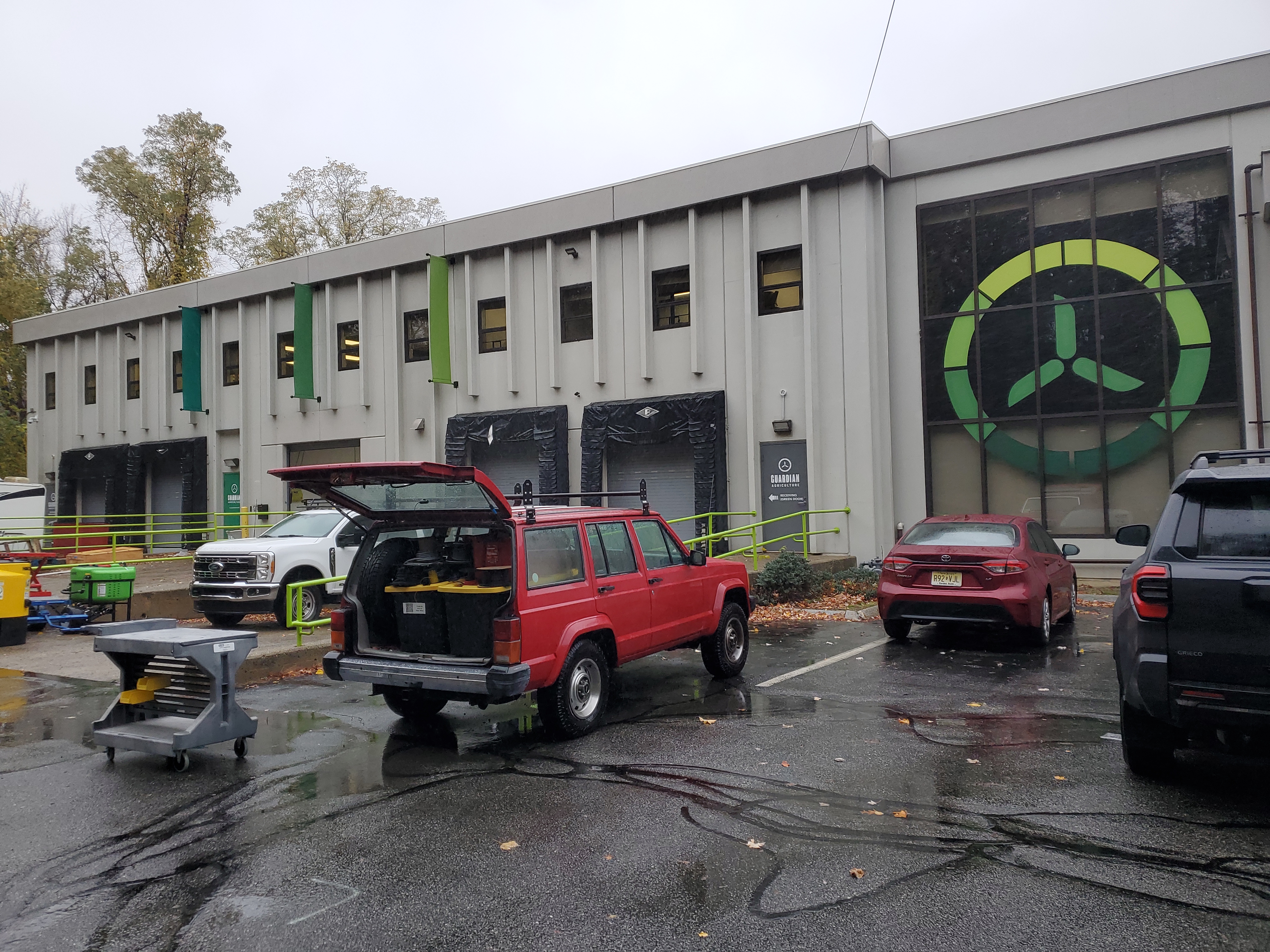
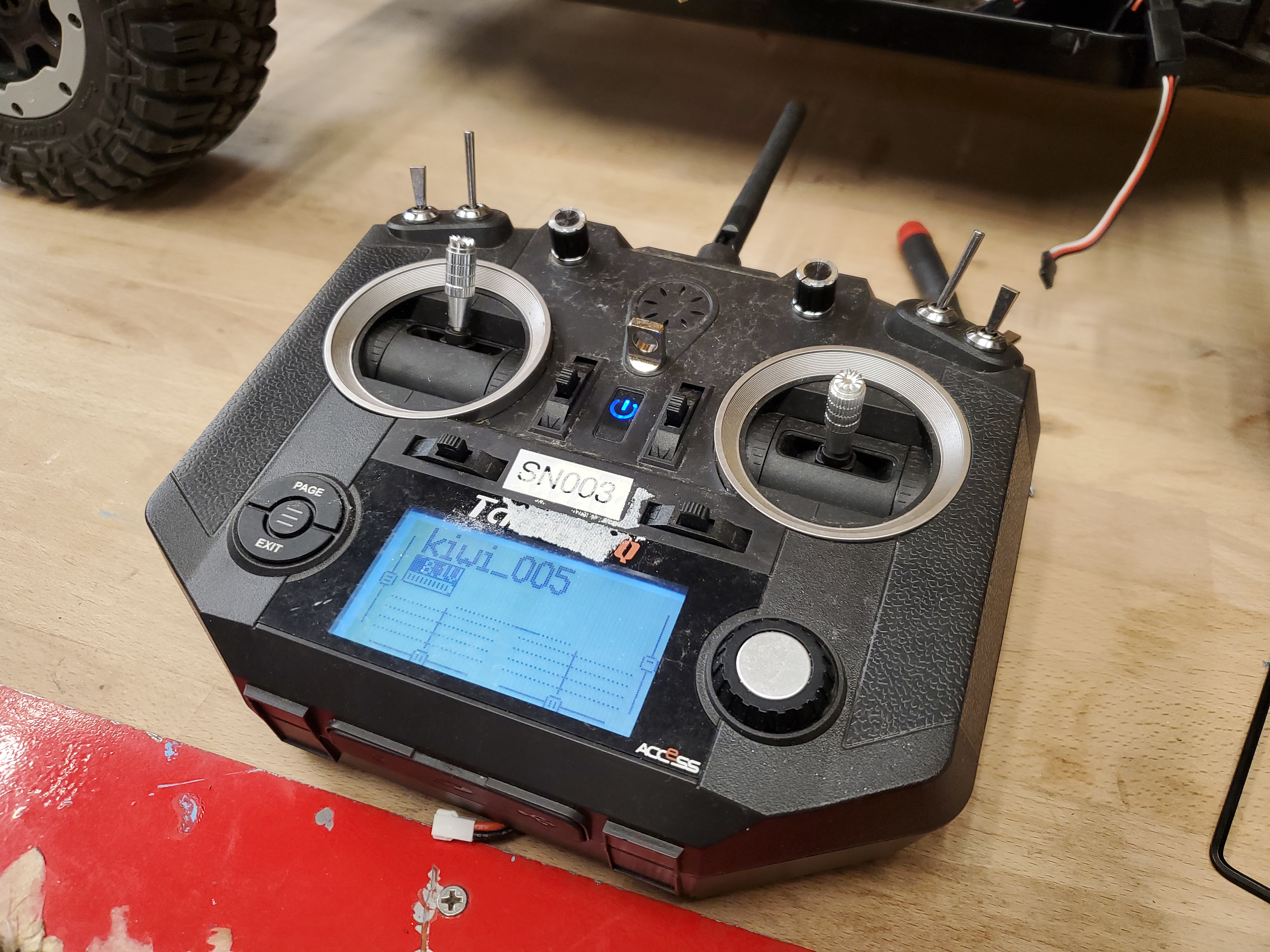
Long ago, Guardian Agriculture was Kiwi Agriculture I needed a radio for remote control and planned to just have a portable display that would follow along with that remote. Yes, as mentioned by FRED, I could set up a ground station and a tripod but the probability of me knocking over a tripod out in the cold is very high. So let's start out with the only actual mount point on the X7, the neck-strap mount. We also have one more 'hard point' that we can pick up, the antenna protrusion that's injection molded into the case. If we can pick up a hard point mount there and the neck-strap, and contour closely to the case we should be set for at least a first pass at a monitor mount. 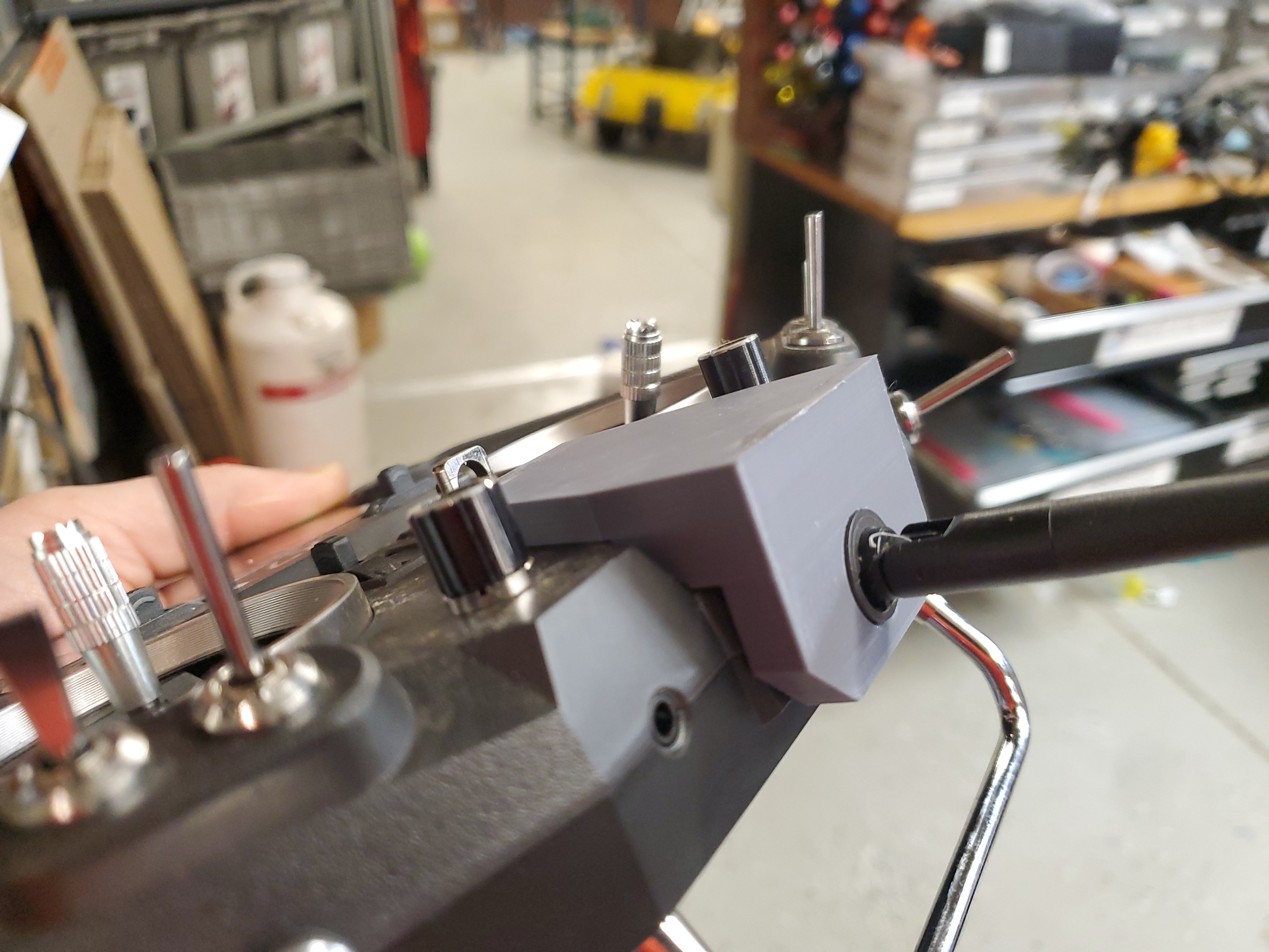
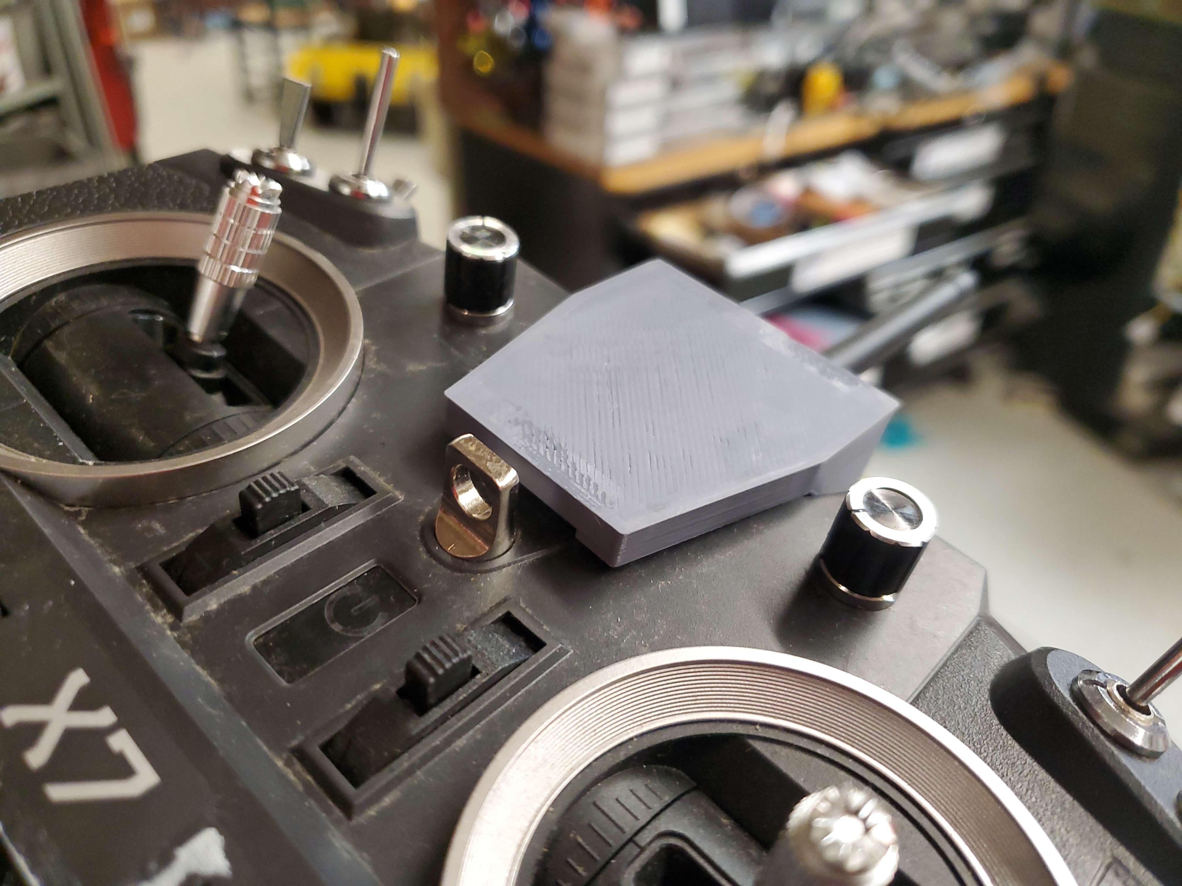
After a number of iterations, I ended up with an M6 long thermal insert to pickup the necklace mount and a heavily walled hole to pickup the antenna mount. This breaks out into one M4 thermal insert for the monitor and two auxiliary M3 thermal inserts for "whatever subsequent spacing modifications i need". Note that I opted for high infill and high wall-count for this part as the lever arm from the monitor is quite high. 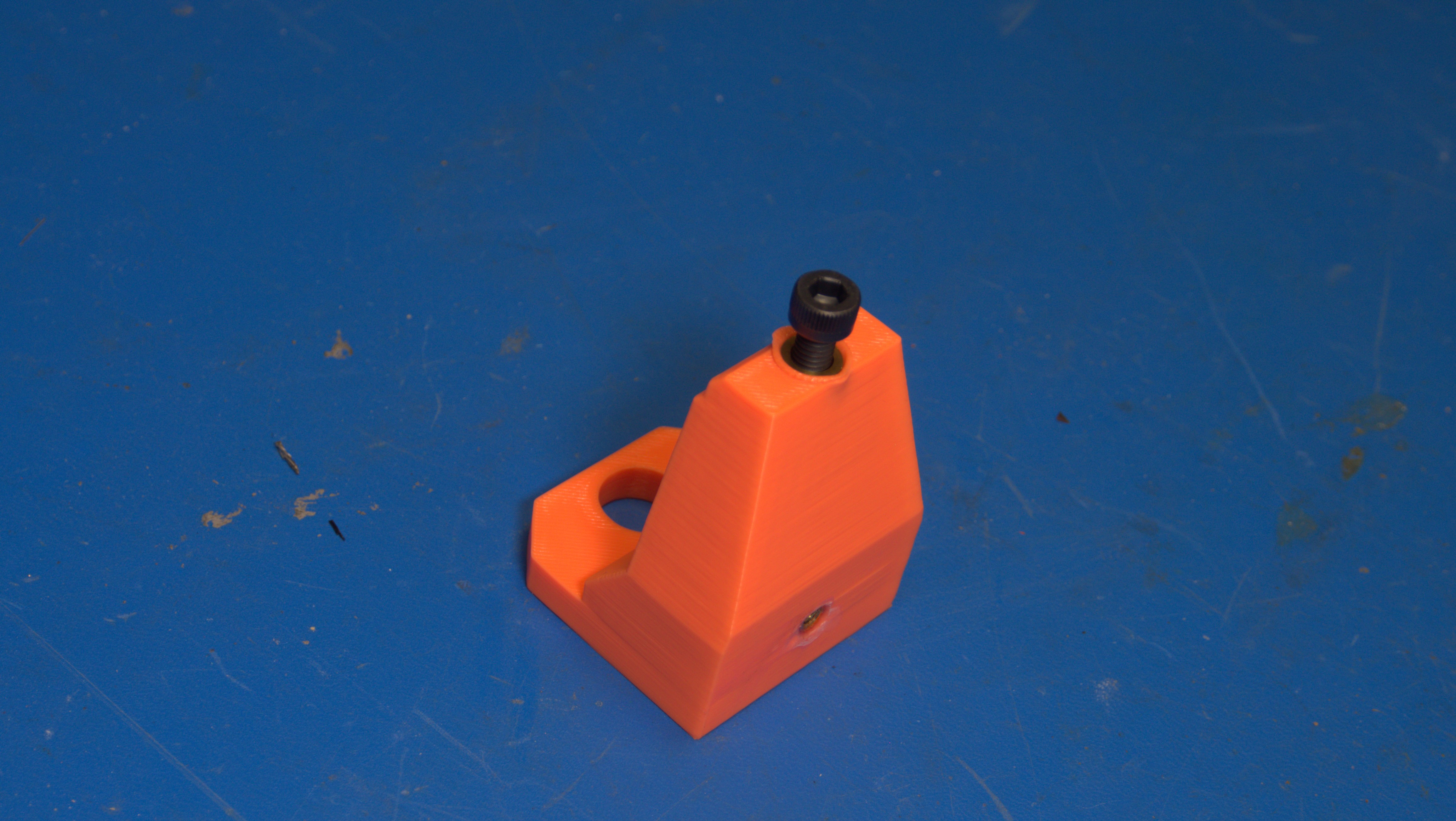
It did end up working out fairly well, especially for a first pass, the monitor is quite heavy and the stock bendy mount was quite limited, so some more iterating to do. 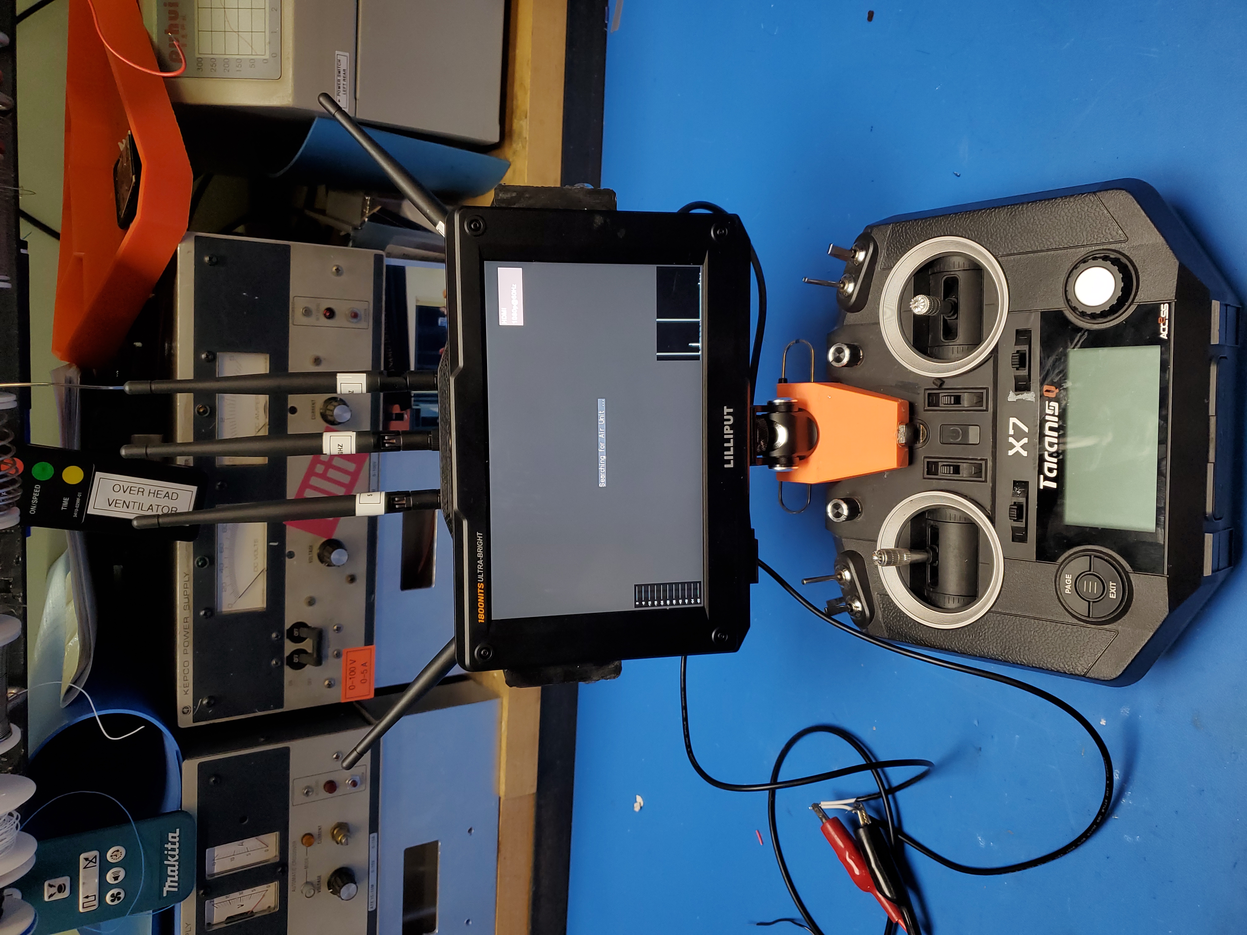
Configuring the Connex AmimonThe nominal pairing process for these two radios is fairly straightforward, and does not require any companion software. To pair the procedure is fairly straightforward:
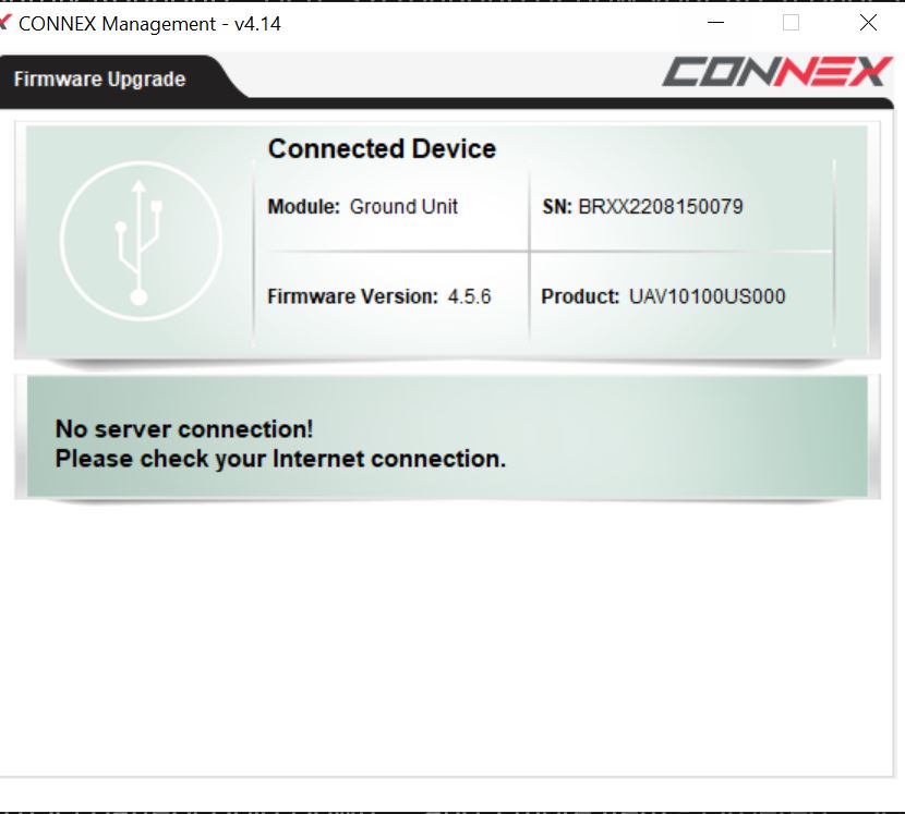
I followed these directions and alas, no dice. The ground unit sat in pairing mode for 5+ minutes and then timed out. I did some digging and found the configuration tool. It did "just work" right out of the box, which is great for ~10 yr old software, but I came upon my first dilemma. The ground unit and the air unit had wildly different firmware versions . I did attempt different variations of the pairing procedure, but alas each go they see each other but refuse to pair. The software tool did have an update feature, but it was too smart, it natively pings a server to check for new, compatible, firmware versions. Those servers are unfortunately gone. Shown below is the "No Server Connection!" message, also showing the mismatch between the Air Unit and the Ground Unit. 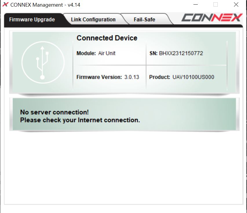
Time to find some help. Between 2016 and now, the initial creator of this hardware / software was absorbed into Teledek, which generally results in previous hardware getting shelved. I was able to get in touch with a support engineer and was given the best support email ever: there's an offline update mode Enabling Offline Update Mode for the Connex AmimonTo enable offline update mode here is the procedure:
The tool is available from the vendor here [Link] and a local copy is available here [Link] For the purposes of this write up, lets assume you are running windows Create a file "local.txt" with no contents in the program folder, C:\Program Files (x86)\Amimon\Connex The latest firmware files are available here [link] and a backup copy is available here [Link]. Download and save locally Unzip the firmware, you should end up with all of the firmware options for US, EU and overseas. 
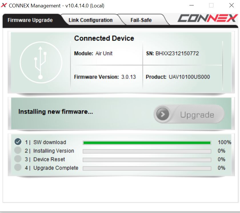
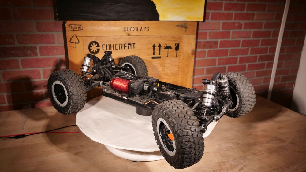
With the secret offline update mode, we now have the ability to push these units to the same firmware version. I started with the air unit and then completed with the ground unit. Shown below is the process, unfortunately OBS screen grab missed the 'open a window to browse to the actual file', but for reference I used "PR_ID_UAV10100US000_PR_NAME_ConnexUS_VER_4_5_61.amn" as the final target firmware for both units. It works! Propulsion ElectronicsThis did come with a castle creations motor controller, however, I did want something that I was able to adjust set points for, and have some flexibility going forward regarding autonomy. I opted for a VESC 75V100, nominally as I had one available and had used one on a previous project. The 75V100 is very budget friendly, and just requires some silicone glue to make it robust enough to survive shock and vibe. Internally there is a large electrolytic capacitor that has no mechanical constraints. For the initial spool-ups, I used a bench supply at 30V, which honestly is inadvisable. Bench supplies are not four quadrant devices and re-gen currents from the motor spooling down can over-volt the supply and cause issues with the controller. Nominally I was mostly interested in verifying that the VESC could run the motor sensor-less 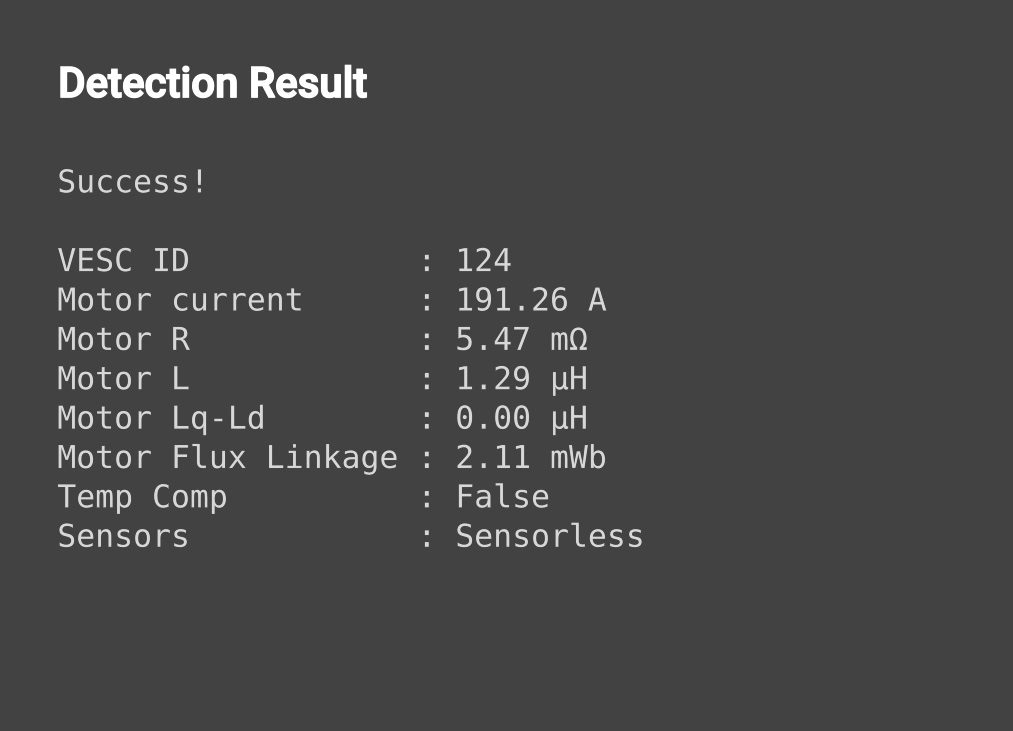
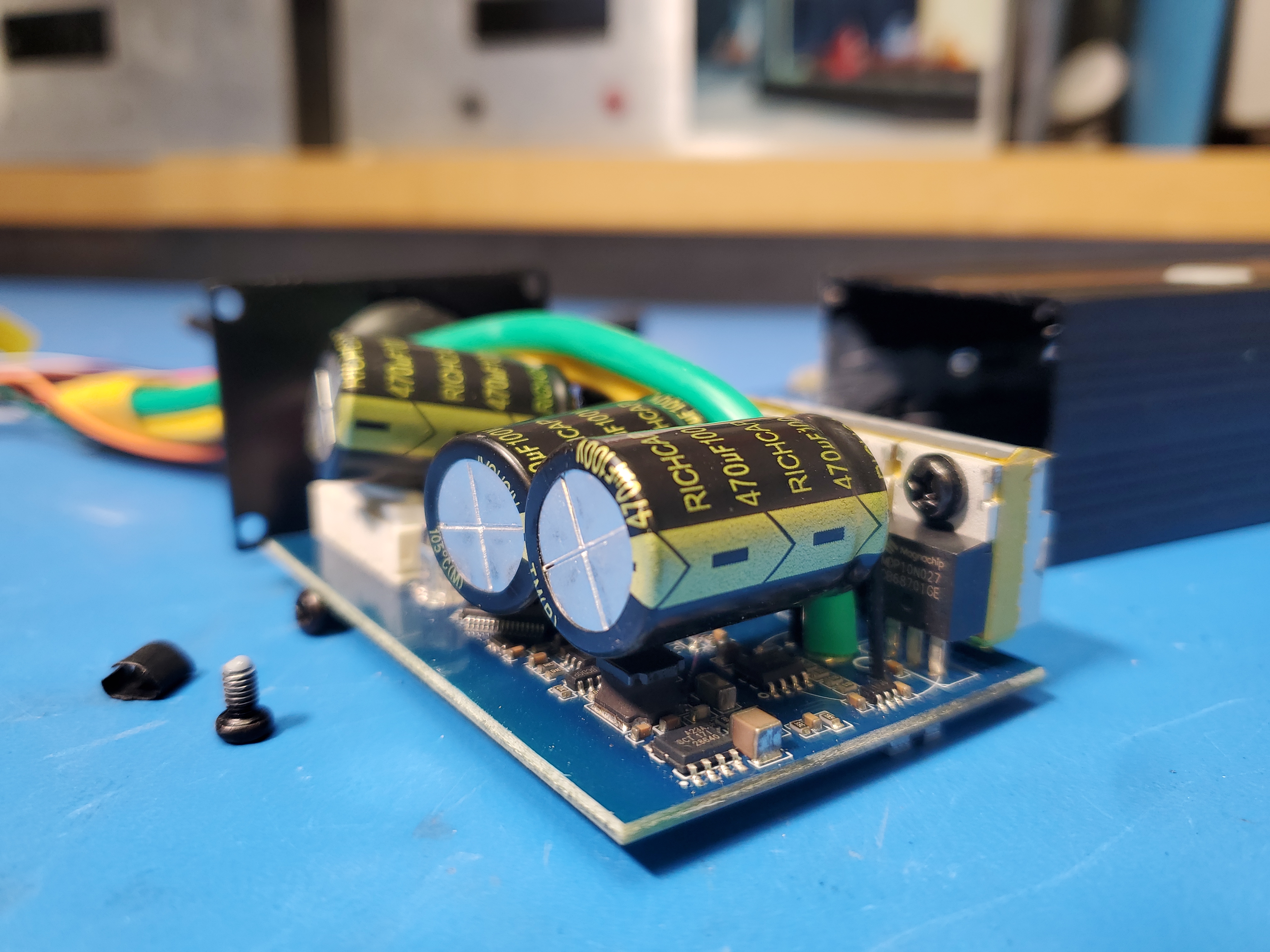
Fortunately, even with a basic tune we got what we were looking for, motor characteristics: 5 mOhm phase resistance and low phase inductance. With this basic information we can do a quick spool up test, making sure to not spool down quickly. This video has audio of the motor spoolup, click to un-mute Speaking of the 75V100, it's a surprisingly good budget controller, however it does have a flaw. Flying Capacitors. Three large electrolytic caps act as the dc-rail stabilization, and unfortunately they are remarkably unconstrained. One seemed to have a hint of glue but the two rear ones were prancing in the breeze. I applied some clear RTV silicone to help constrain them and protect from moisture ingress. RTV was also applied to the cable gland input and top mounted led optical path, to help keep moisture out. 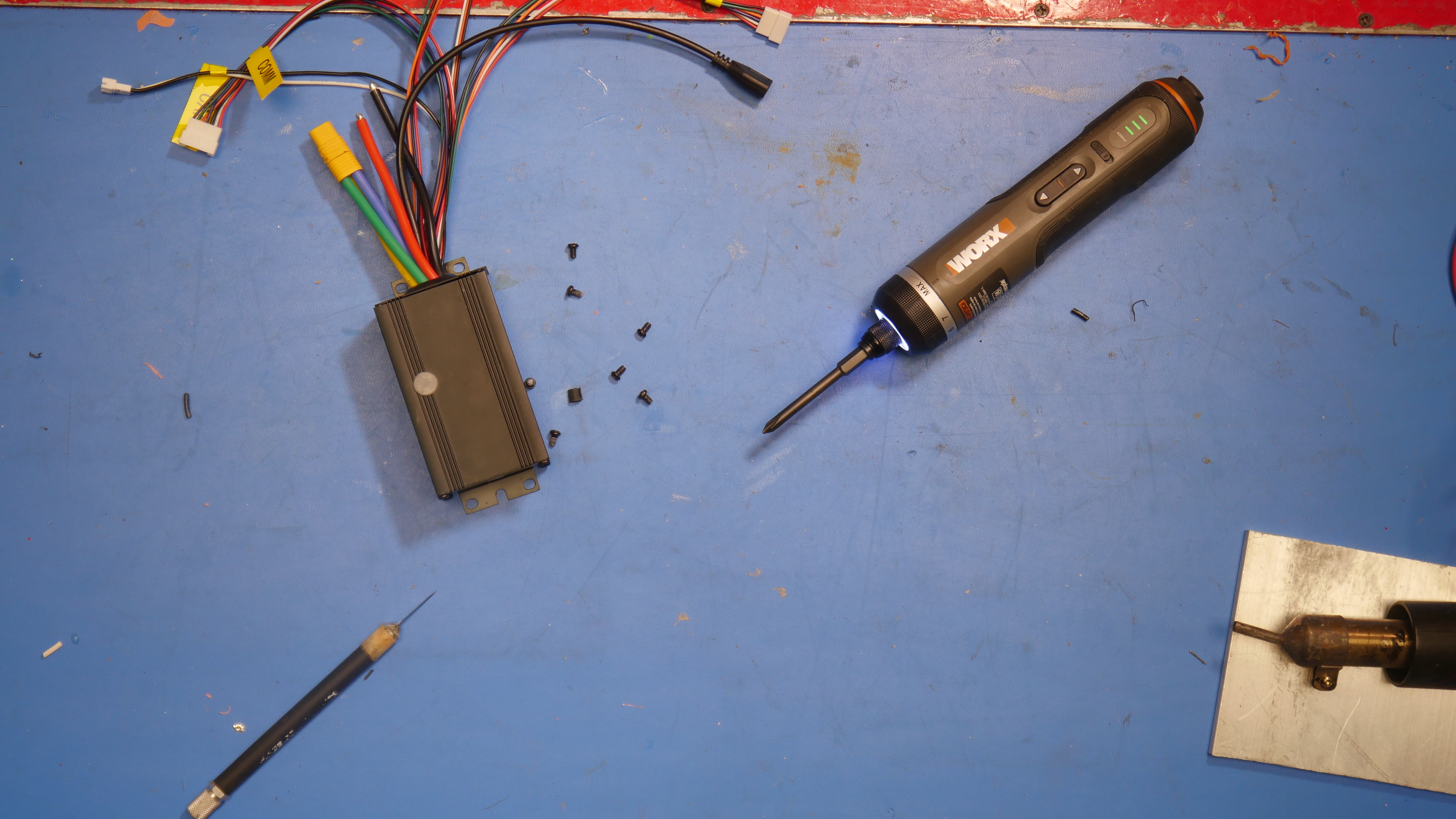
Something that needs some work is pre-charge. The plan is to use the two DeWalt packs in series, or an equivalent 10S battery. This is a nominal "36v" system, with 42V max. Slamming low impedance 40V into the controller is not ideal, so having a way to slowly fill the controllers capacitor bank, and then fully enable the DC battery rail is ideal. Whatever the approach, we do need to make sure that it survives shock and vibe. Some relays, and especially circuit breakers have terrible vibration performance. Due to some timing constraints, I'm opting for enlightened user instead of having an automatic pre-charge start. A simple 10 ohm resistor and push button jumper across the main contactor switch, the user pressed the button for 5 seconds, the motor controller capacitors fill and then the "ON" switch is toggled. This does have the downside of a user hard-turning the controller on with the toggle switch and potentially damaging the bus-capacitors. I am glad that they actually chose 100V rated capacitors, I've seen some controllers with wildly under-specified bus-capacitor voltage. Lets see how the setup performs with no-loadAfter some bench testing, I plugged in the gear ratio and did no-load testing of the propulsion. Keep in mind, wheels-unloaded testing is wildly inaccurate for speed and full motor RPM may damage the motor, but we do get some hints at power requirements and a rough estimate of how the remote speed mapping will track I was hoping for some more stable numbers for wattage and DC link current. I'd estimate real-velocity would be 30% less than no-load velocity, which puts speed mode 1 at 20MPH max, speed mode 2 at 30MPH max and speed mode 3 at untested max speed. Assuming I can maintain a Bluetooth link for long enough, it should be possible to repeat this with the system loaded. Power DistributionWe have two separate systems to power: the camera-gimbal assembly and the chassis The ChassisThe chassis consists of two 5S swappable battery modules connected in series, to create a 10S equivalent pack. This is a 36V nominal battery able to source ~40-50A. This is a bit under-sized for the motor, however its not clear if a chassis this size actually needs ~3kw. The ~36v nominal battery needs an e-stop, and a pre-charge to route power to the controller safely. A DC/DC is required to provide power to the steering servo, which can pull upwards of 5A at 5V. The 900 MHz radio receiver for the chassis requires a 5V feed for logic power. Otherwise an auxiliary 12V feed would be great for indication lights. The Camera-Gimbal AssemblyThe Camera-Gimbal assembly is a single ~14V battery that supplies the gimbal, camera aux power dc/dc converter, and video transmitter directly. The 900 MHz receiver for the gimbal controls will be supplied by a 5V dc/dc converter from this pack. E-StopA large push button style e-stop would be useful for stopping a runaway chassis. Generally, in combat robotics, one of the most important tests to perform is the fail safe test, where you command 100% of whatever channel is required, then power off the radio. This equates a loss of signal and should result in the system entering whatever the fail safe state is, generally a full-stop. This isn't necessary on the gimbal-camera itself, a single switch will enable power from the DTAP battery to all of the associated systems. TelemetryPropulsion ReceiverThe stock antennas used on the 900 MHz FRSKY receivers are intended for rc aircraft, and while their performance is great, they are hard to waterproof and install on more fixed-application hardware. After opening up the receiver I was fortunate to find UFL connectors, which are fairly common and easy to get adapters to SMA / RPSMA antennas. To remove the existing antennas you do need to carefully pry at the existing dots of retaining glue as to not damage the board mount connectors. It is highly likely that you will damage the mating antenna connector. Once the SMA panel mount connectors were installed, i routed the UFL adapters to the board and reinforced them with DP100 2 part epoxy. Hot Melt glue could have worked here in retrospect, but either way the cables were now fairly firmly attached. Next up was to run all the associated signaling cables. A cable gland tries to keep moisture out of the receiver box, which contains the glue-potted receiver board. 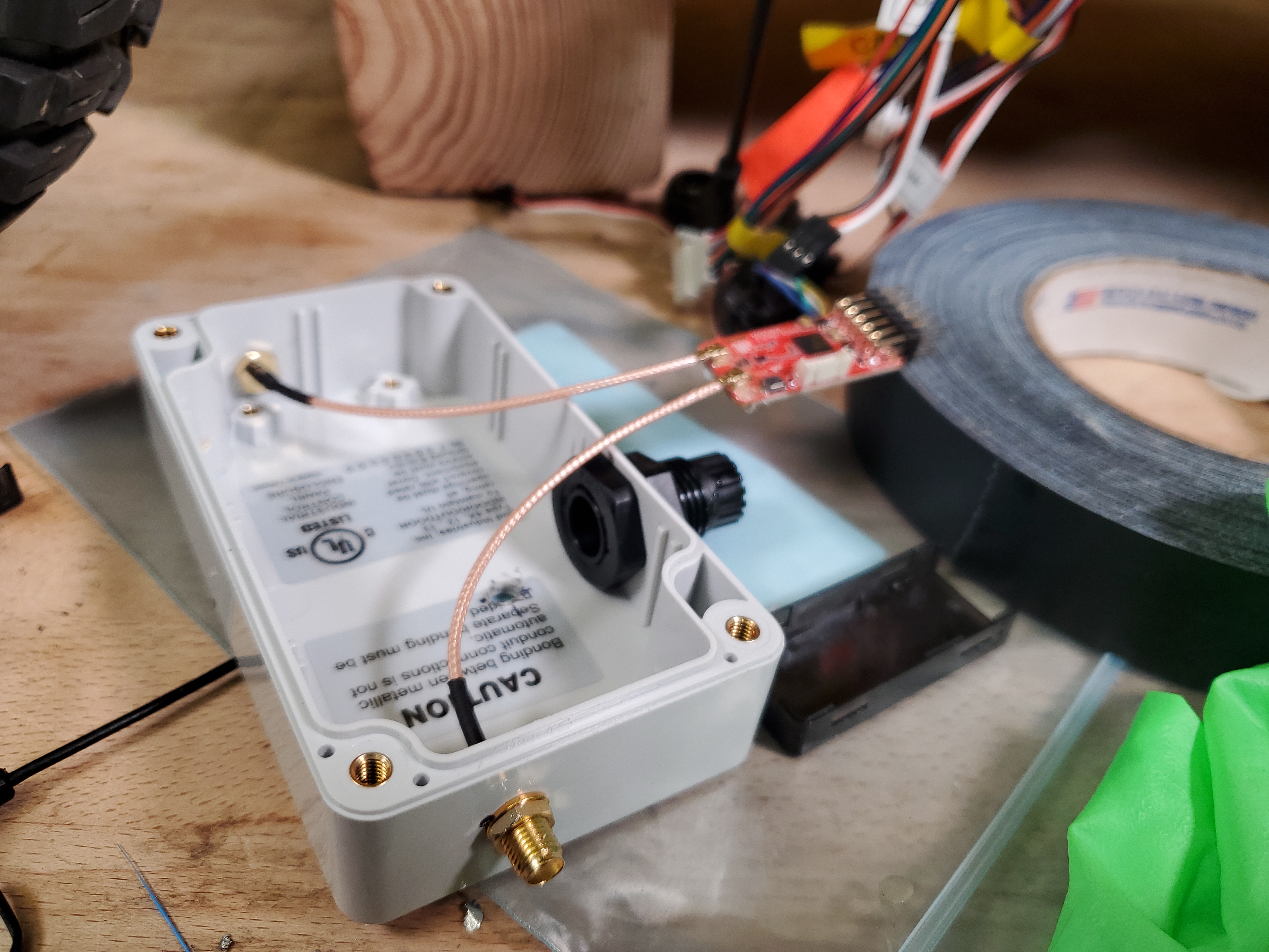
I picked up one of the existing chassis screws and used a slightly longer pan head screw to mount the receiver box to the frame. Two 'omni' 3dbi gain antennas were used. These aren't that constrained so its likely that some additional mounting hardware is required to keep them from getting ripped off by the electrical connector. Of the inputs we have the basic PPM control of the VESC, a channel for the steering servo, one for the headlight/taillight relay and finally the SBUS data from the current / voltage sensor. Remote Camera Lens ControlMotorized lens's are nothing new, but remotely controlling a zoom lens from an R/C controller does not have an off the shelf solution. First problem to solve is how the heck do you remote control a lens anyway. My go-to camera and lens stack is M4/3 or micro 4/3 which is technically an open standard. You still pay to read / view the standard, so 'open' is a loose term. One route to control a lens is to talk to it directly, IE learn the SMBUS / SPI communications between the camera and the lens, and spam whatever the zoom in / zoom out packet is. This is a bit fiddly as it requires. A communications interception ring on the mount. Fortunately there's a remote shutter port, that is intended for remote focus and remote shutter. It uses a 1/8 headphone jack, and as it turns out can also be used for zoom and focus adjust? Like most things, this is completely undocumented. To test this out, I purchased a very budget remote zoom controller, which had both Panasonic and LANC options. 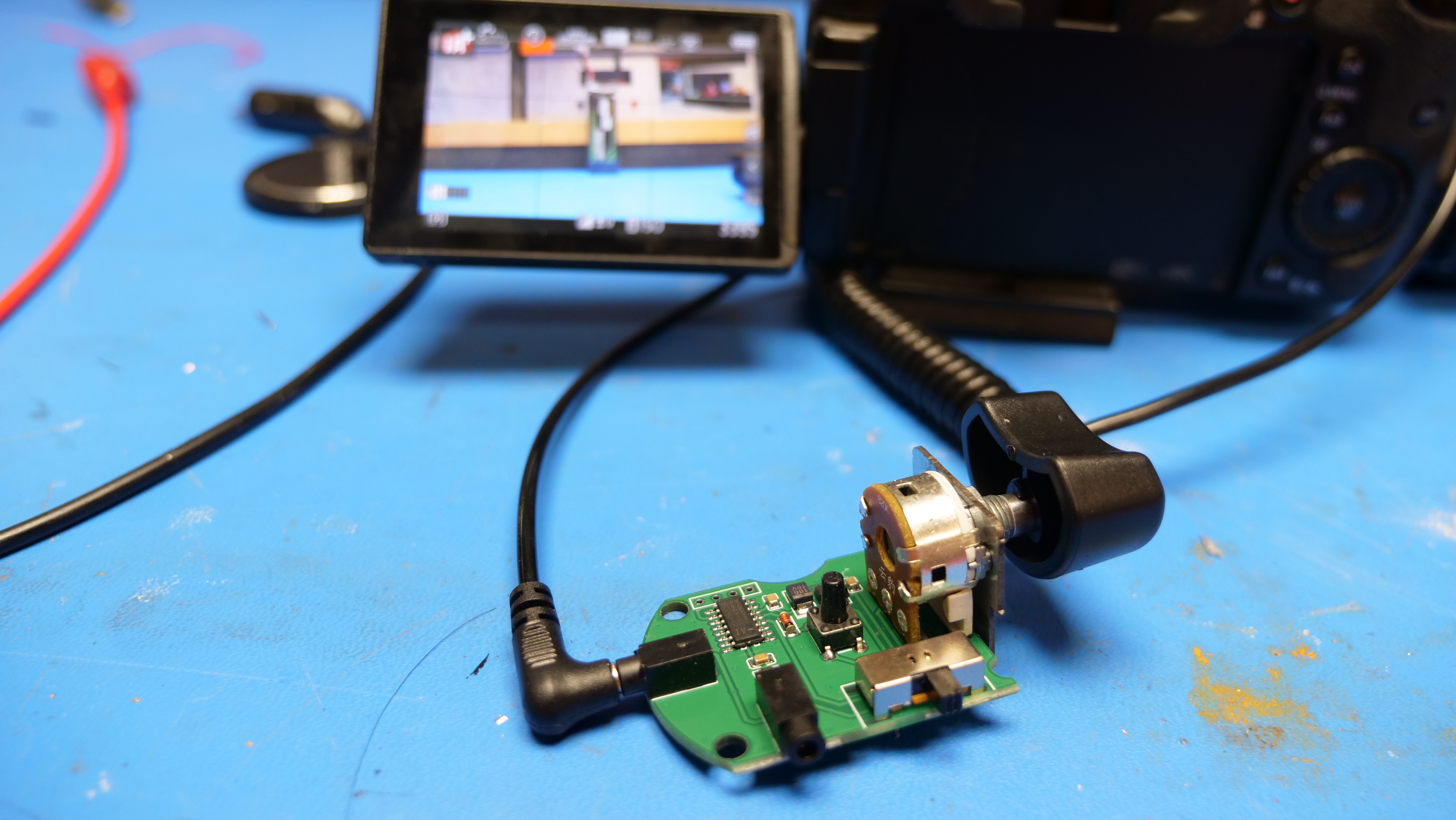
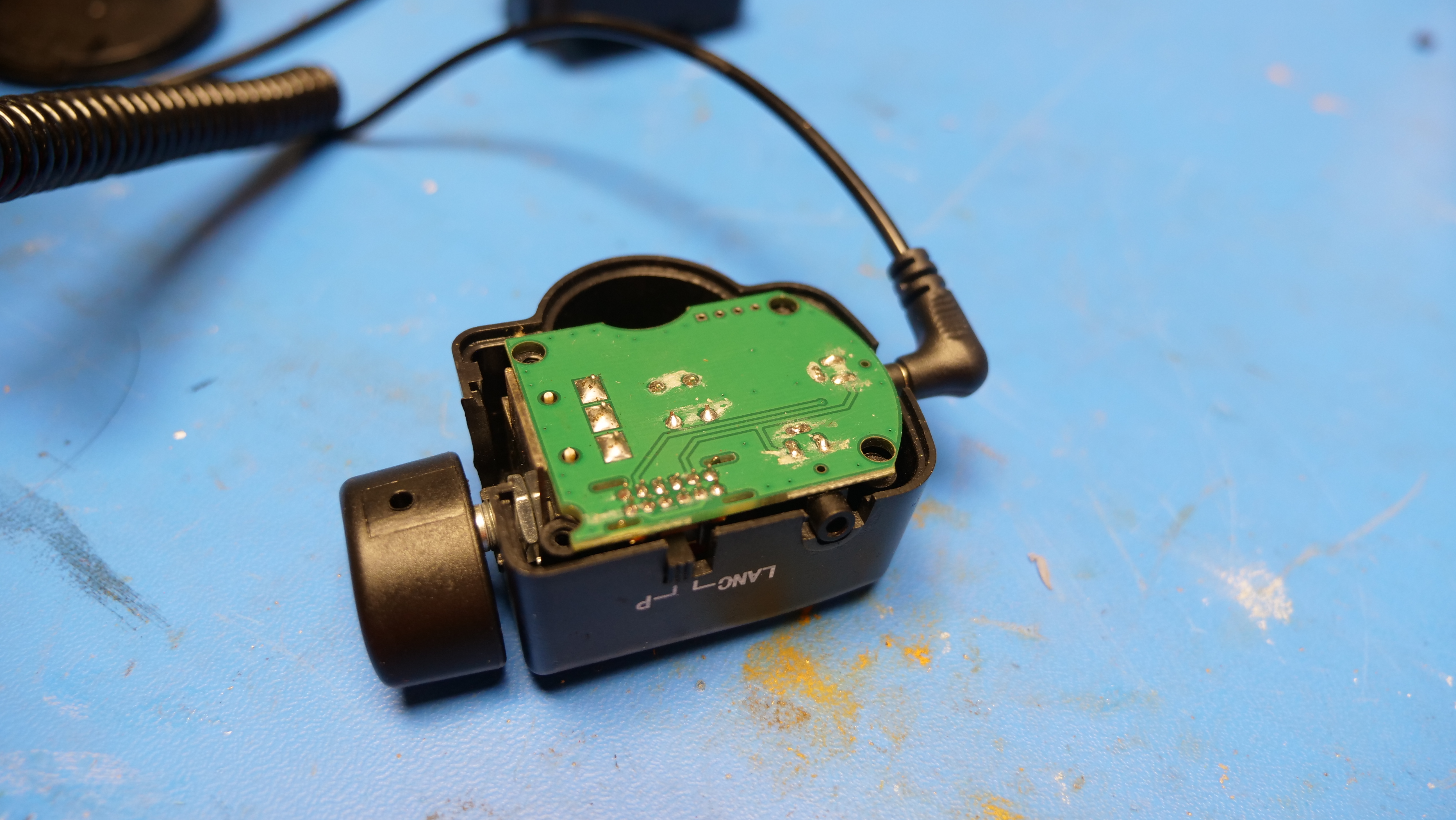
I opened up the controller and found the three pin connector and scoped out the signal while twiddling the zoom state knob. I really expected a modified serial or equivalent, but i found that Panasonic really just uses an analog value. Initially I anticipated this being a voltage based signal, IE: a DAC was sending specific values, but then i noticed that, no, while in Panasonic mode, there was not actually sufficient power to both run a micro and simulate various voltage states. My observation is on CH1 of the 3 wire jack:
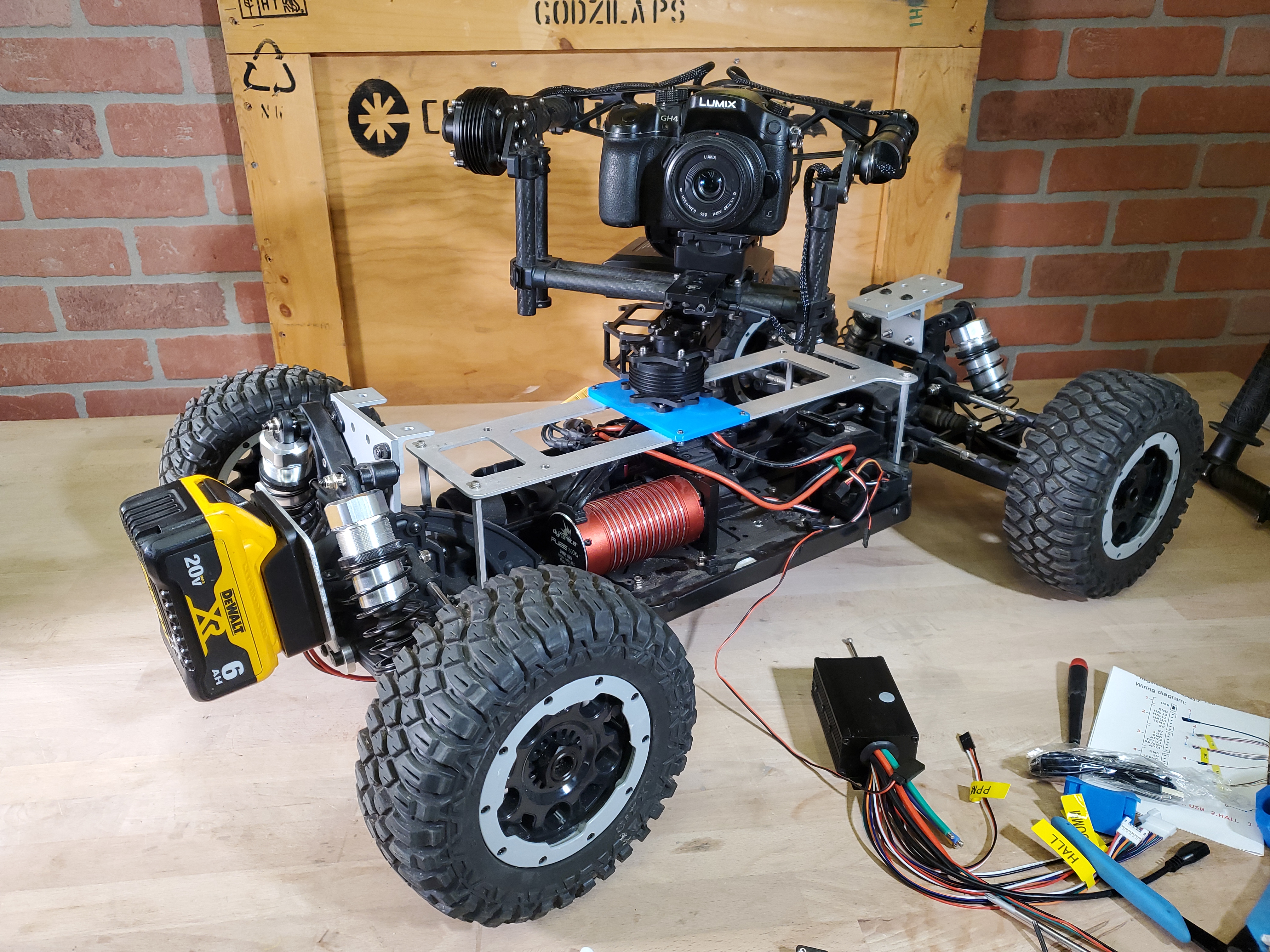
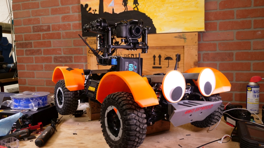
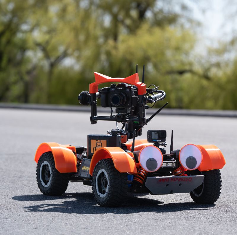
760 mV 1.44 V 0.80 mV Instead, it appears that the controller end of the module is just providing various resistances, which the camera internally processes. Given that I'm planning on using a micro controller to take in R/C PPM signals and twiddle the camera record / zoom state, it does seem easier to use a digi-pot to interface with the camera. I did end up finding a budget friendly remote controller that did both zoom and focus control. Given that these resistances are unknown and I'm already at work on this, let's just make a table of resistances and sort out what the camera does with them. Once we have this lookup table, lets then make a micro controller process inbound PPM and fully control the camera through the shutter port by controlling a 10k digi-pot. Power IndicationFirst Shakedown TestSo its time for the first shakedown run, at the time of writing its presently dismal gray season in Massachusetts, and the streets have dried of their snow remnants to an extent. For this test I have a Panasonic GH4 mounted to the Movi M10, a GOPRO Hero 10 hard mounted to the frame, and a camera statically on the street to display what this looks like from the 3rd person view. The M10 is incredibly not balanced well mechanically, which as it turns out is actually very important . No software tuning would compensate for that amount of offset balance on the camera's tilt axis. I also discovered that the HDMI cable was getting caught and causing the gimbal to struggle at end of range. I was really happy that this whole setup survived 30 MPH, that is a lot of speed for such an offset mass vehicle. I did get some guidelines on gimbal-ing:
This literally means what it says, the tilt axis should actually mechanically be very easy to flip, I completely skipped this step and it shows in the footage. Initially, I encountered issues with cranking up the tilt axis gain and this is likely why, unbalance from step 1. My camera is inherently small, a GH4 is ~560 grams, and the lens I've opted for is also fairly lightweight. Why a GH4? There are known issues with camera IBIS (In-Body Image Stabilization) interacting with gimbals, producing wobbly footage. The GH4 can shoot 4K but also lacks IBIS natively. I could opt for a GH5-S or a camera with a lockable IBIS, but those are somewhat pricey. A bit of rough drivingTo keep things conservative, I did implement some very soft acceleration curves as well as a large amount of hysteresis on the change in direction. This was a bit too conservative and I ended up doing a bit of smashing. A steering linkage failed on a curb impact and so did the Gimbal battery 3d printed mount. Adding inertiaOne of the interesting notes about the Movi M10 is how it changed over time, notably how the top ended up mechanically closing the loop. After some feedback from experts, adding in a mechanical linkages to close the loop, and adding mass to compensate for the fairly lightweight camera both would have a significant improvement on axis tuning. To add mass, I did want to maintain a symmetric distribution, and the simplest path was just to use the existing carbon fiber uprights and have them house large M10 bolts. To make life simpler, I used the 3D print to capture the nuts, which hides them slightly out of view. This part was high-wall-count and relatively high infill. 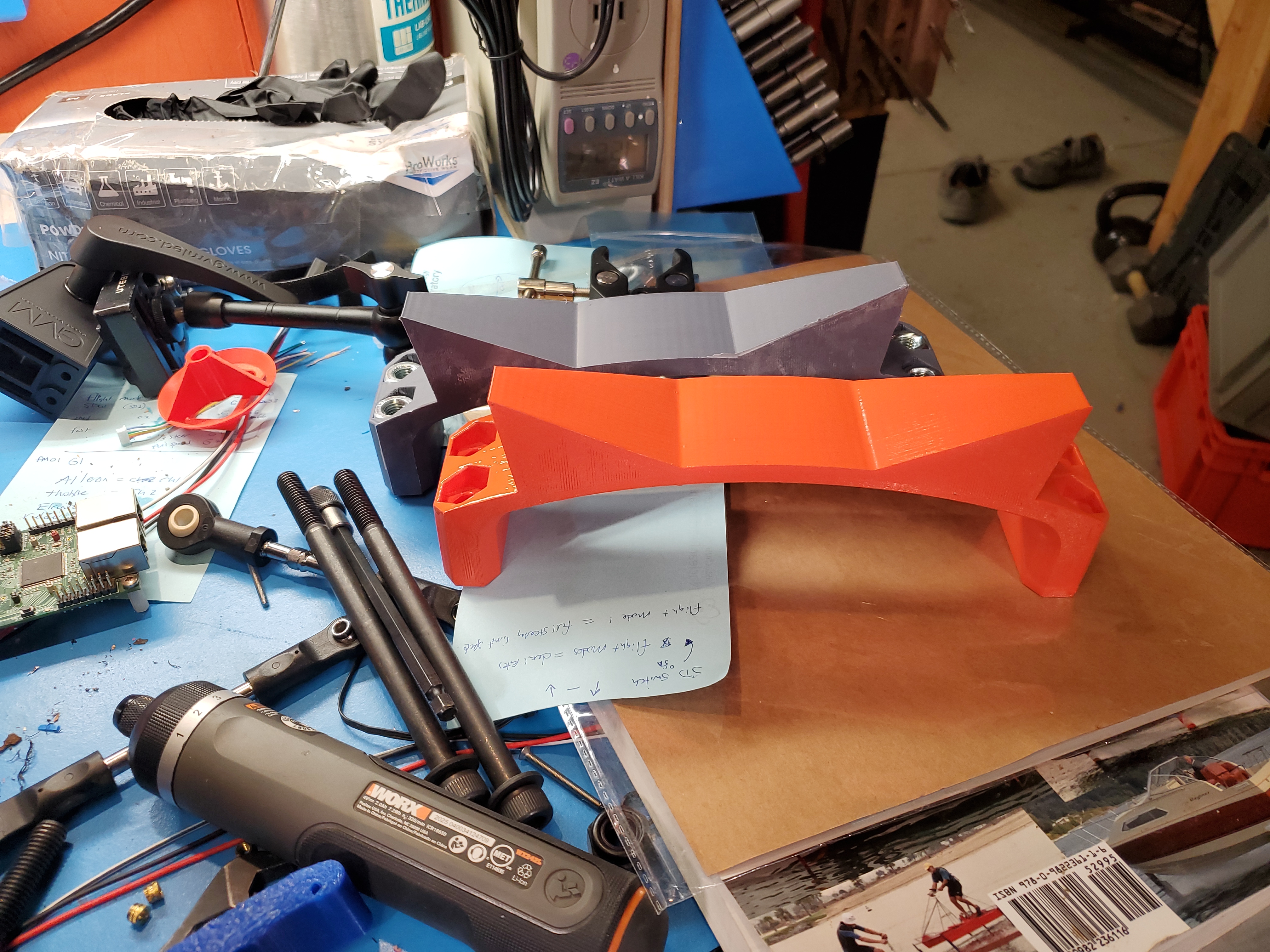
Compensating for the additional massThe ride height of the whole vehicle from the first shakedown test was barely passable, the tires found the flexible TPU fenders fairly quickly. Interestingly this is actually a spring + fluid damper, the inside was filled with what appeared to be mineral oil. The stock shock absorber had a reasonable spring, shown in black. Given the timeline i opted to find an equivalent from mcmaster-carr, and subsequently coat it to match the vehicle's color scheme. I ended up opting for this 2.5" spring, which has a 97 lbf/in deflection. We know that the full mass of the vehicle is ~50 lbs, so we expect ~0.5" of ride height reduction in a static environment, on a 2G load, we should see 1" of deflection, which is tolerable for the existing fenders. While this spring is somewhat short, it does have the correct ID/OD to work with the absorber. 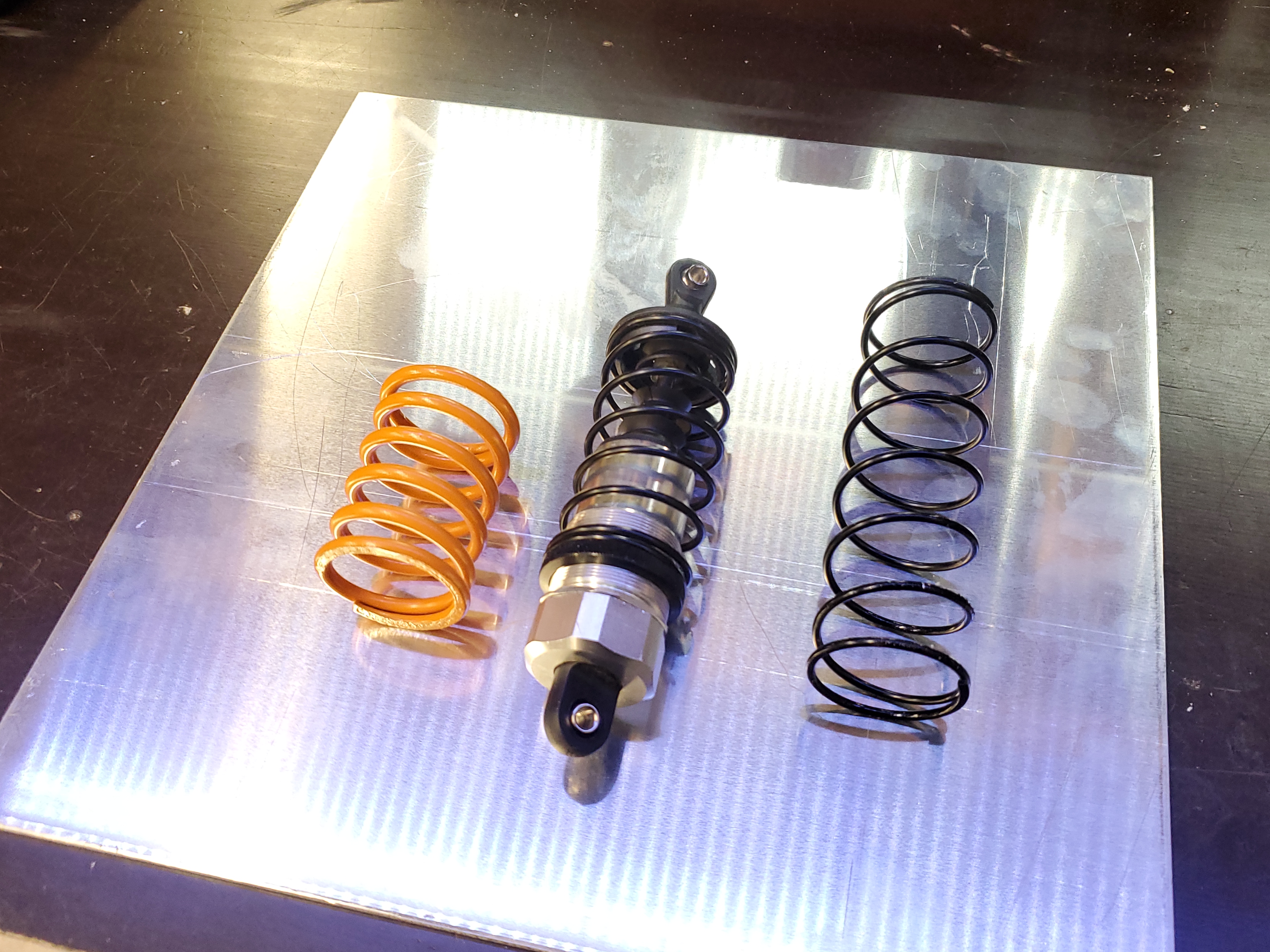

A smashed battery mountOne of the casualties of the shakedown drive was the battery mount. For this run I was using a 120W D-Tap battery, which does have some inertia, it's positioned to offset the mass of the gimbal, rotation-ally. This mount was a 6-wall 75% infill PLA part, however it looks like the infill to wall boundary was not terrific. It sheared perpendicularly to the print axis which is wild. Curiously in an impact, this printed part has to translate a lot of torque, specifically if its a solid part. I had the option of discerning how to make this out of a cnc aluminum block, or try something simple, print it out of a flexible filament. 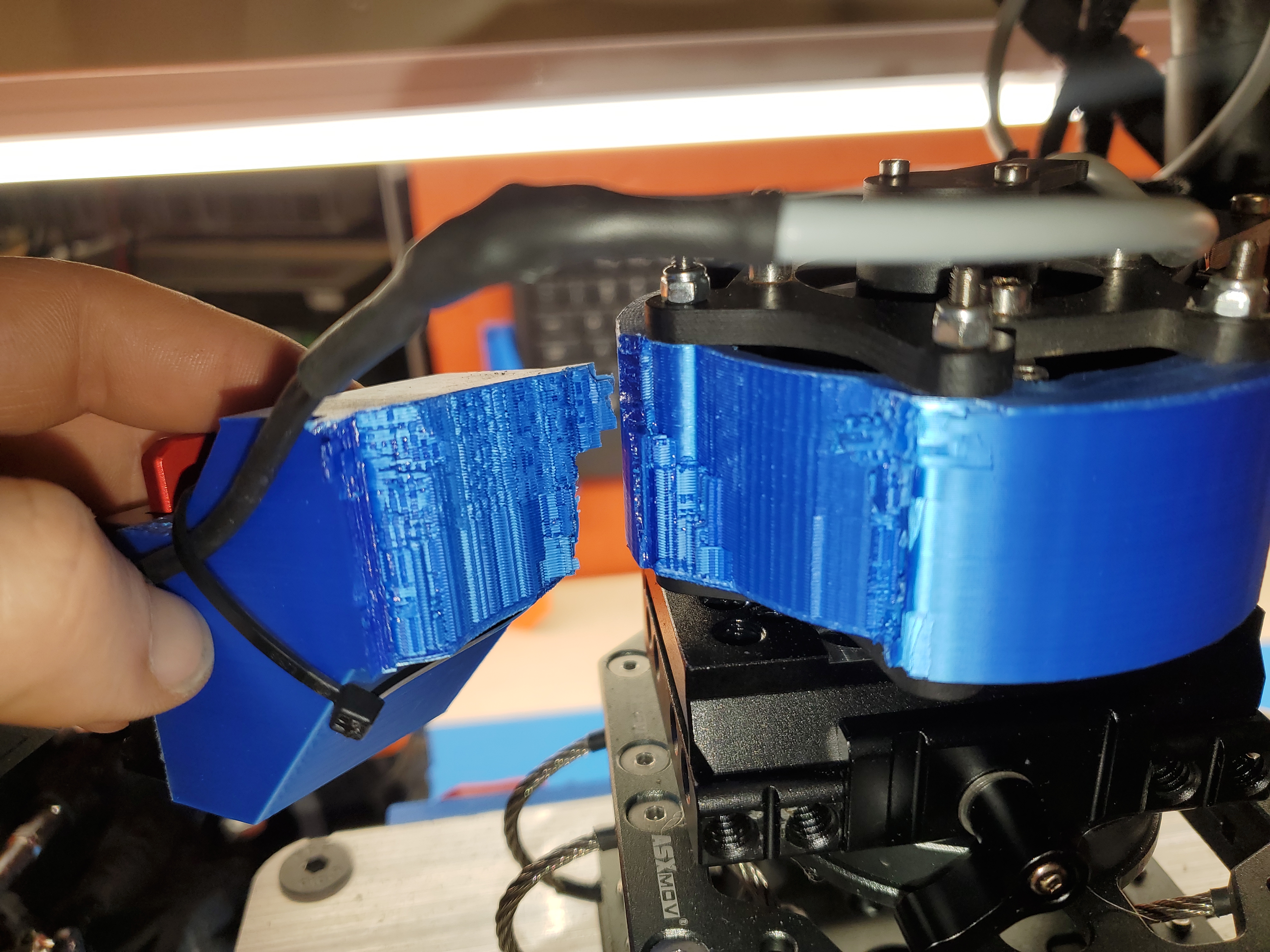
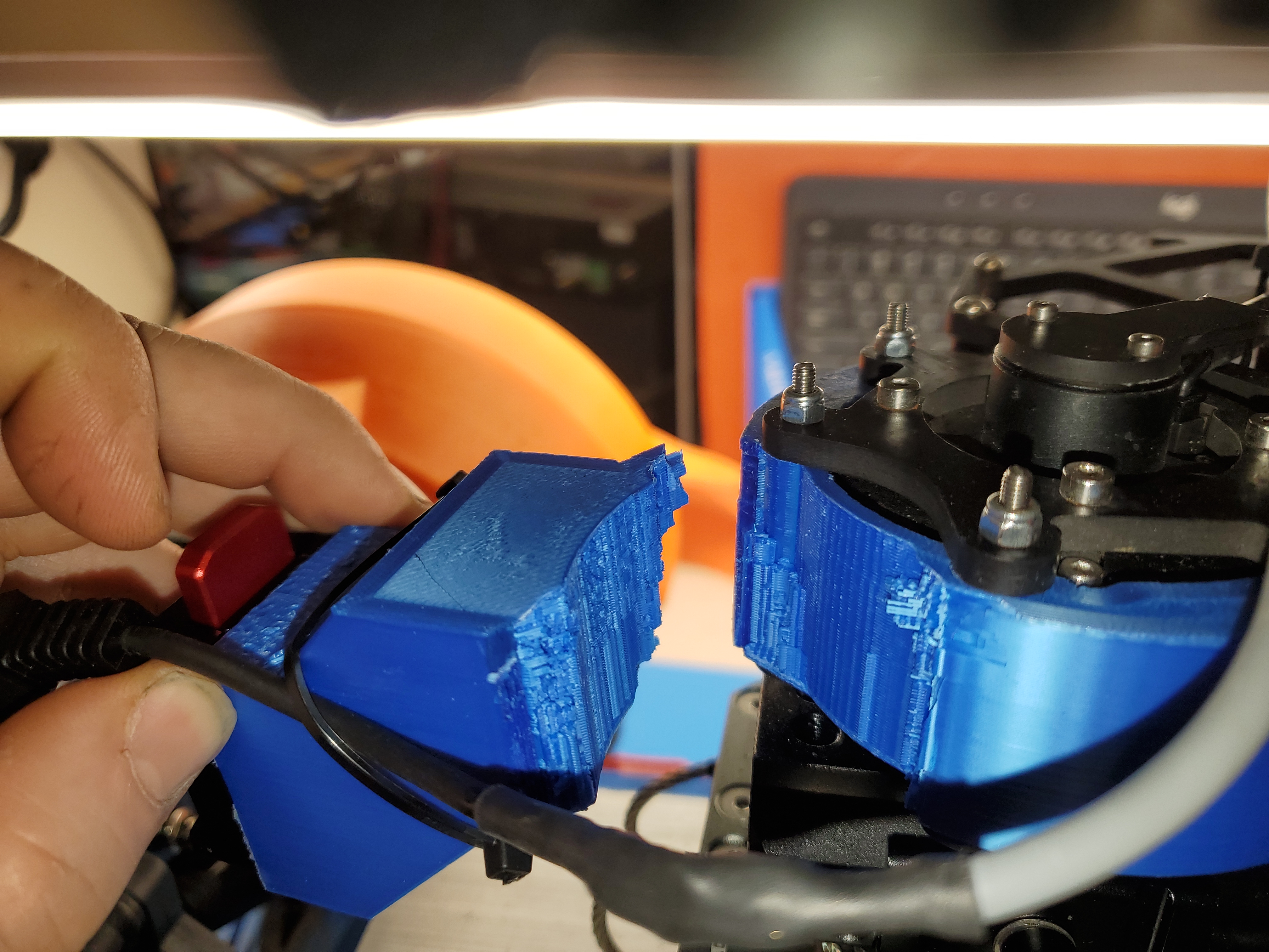
The new part, made of high wall-count TPU is mechanically a bit different than the initial design. We still pick up the four M3 shoulder screws the Freefly Movi M10 use on its theta-0 motor, but now a long M3 screw captures the plastic near the interface and translates force out to an intermediary aluminum plate. This allows the tpu to absorb some shock while providing a mechanical path to keep the battery retained. The aluminum plate was a simple trace + band saw activity, a punch was used to transfer the holes from the DTAP mount. 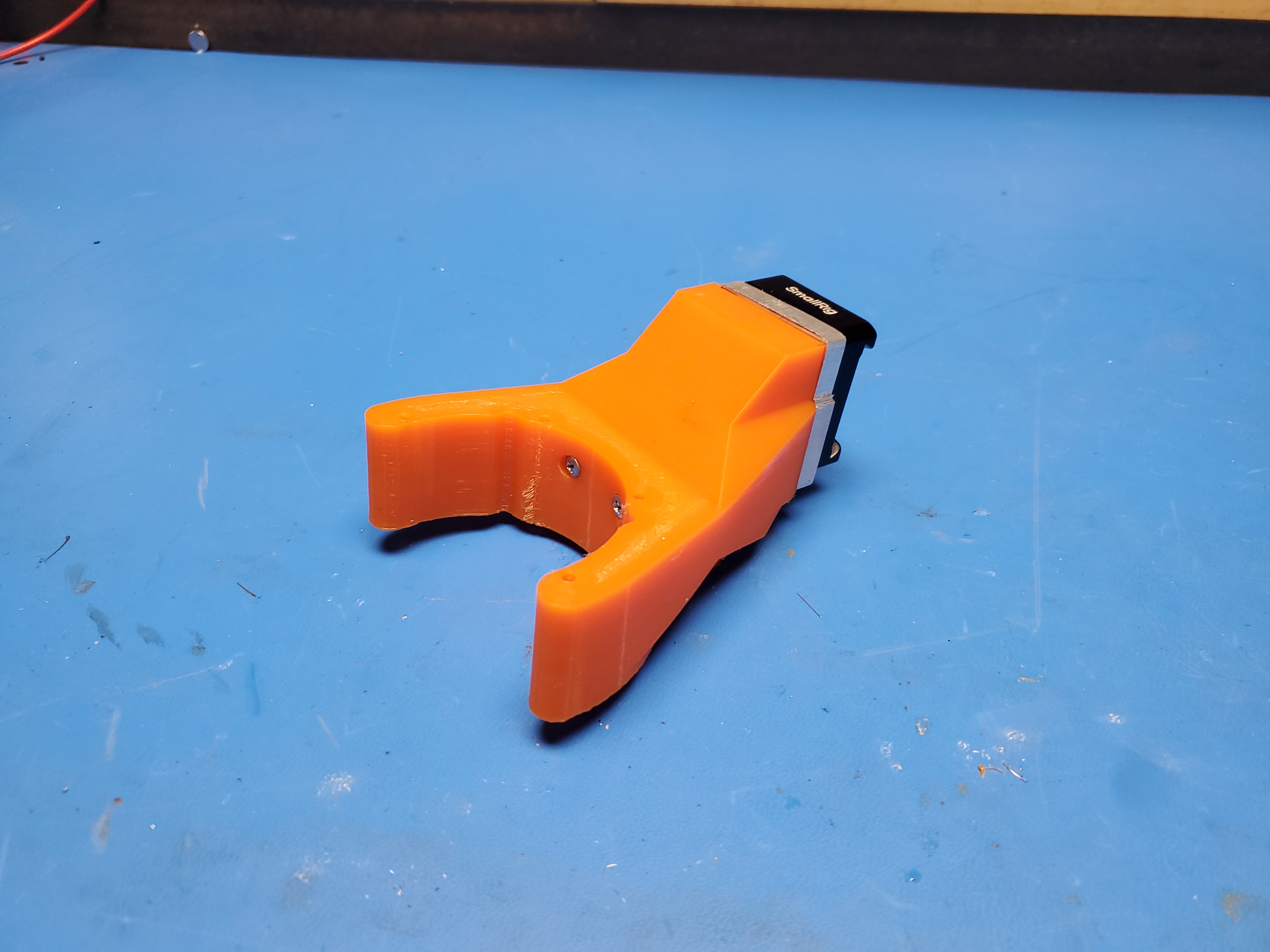
Ice RacingSome quick backstory: A frozen lake solves a problem that may be not inherently apparent, Roads are not free. Lets say you put together a shifter kart or elaborate experimental vehicle, where can you actually test it?. Driving on public roads can result in a fairly sizeable fine, and there's not a lot of space to determine the limits of whatever the vehicle is. Tracks exist, but they are pricey and do require a bit of transit to get to (a 3 hr drive up to New Hampshire motor speedway). A frozen lake is limbo, there aren't really rules or obstacles. I periodically organize ~five dozen silly folks and their assortment of contraptions on a lake day to get fresh air, get some speed and have a blast. 
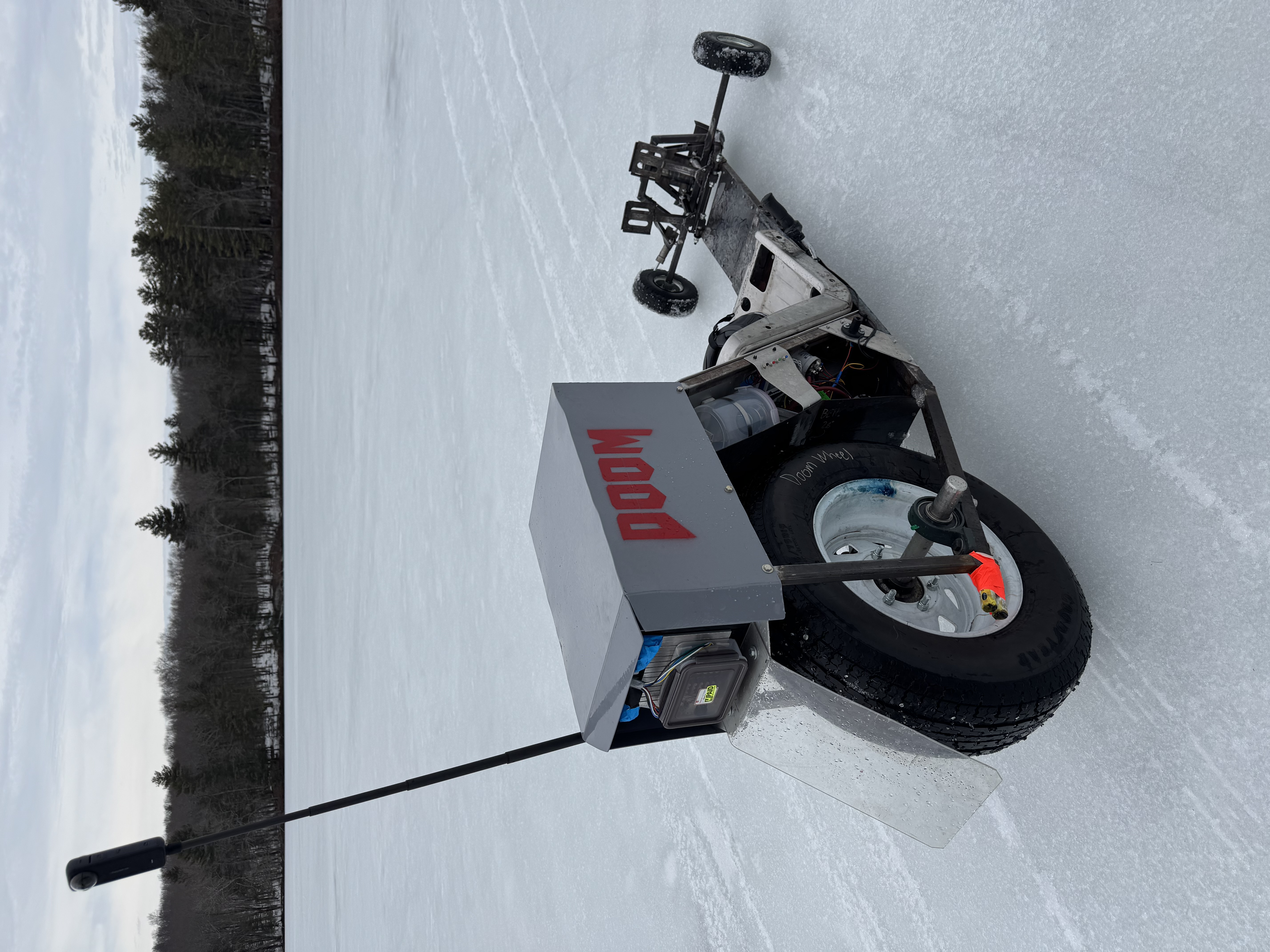
Over the course of the morning, after a lot of unpacking a small tent city appeared. This consists of safety gear, ice sample hardware, food, a warming tent and associated gadgets and gizmos. So here's the debut day for chase camera, piloted somewhat randomly by whoever was available. We observed that the dual 6AH DeWalt batteries worked out pretty well, netting nearly 30 minutes of exceptionally fast zooming around. Its goofy but it worked so much better than I had hoped. Here's a mechanically stabilized shot of Shane on his tiny kart, just take a second to think about how rough that surface is and how smooth that chase footage turned out. A wonderful shot of MEGA DOOM SLED as it majestically races across the frozen lake. Camera Upgrades & Warm Weather Testing:Now that I knew a normal Panasonic GH4 would survive zooming around a frozen lake without flipping over, I had a bit more confidence to find a camera with better image performance. While a number of the shots from the winter ice racing event were stellar, the color depth (and the overcast sky) really made color correction difficult. So next up was the Panasonic GH5s, where the 's' is for 'not stabilized'. Comically camera image stabilization and mechanical Gimbal stabilization can fight each other, and it's very much dependent on the specific camera internal stabilization mechanism. The GH5s has a fixed sensor, but one that's about an order of magnitude better, performance wise. There are plenty of 4K capable cameras as of this write up (2026), and while the GH5s is getting a bit older, it's a lot of camera for the (used) price. I purchased this one used for ~400 USD 
With this upgrade we're essentially quadrupling our data captured, but it's so much more than that, netting two extra bit depth for color information gets us out of the muted land of high saturation and into a way more vibrant color space. For a moving contraption doubling the frames per second also nets more data if any post process stabilization is required. Mounting the new camera was incredibly straightforward and only really required a little bit of re-balancing and a small change in the HDMI cable routing to adjust back to full sized HDMI. Fortunately the GH4 and 5 both use the same style battery, I was able to continue using the external power battery adapter. 
With some warm weather rolling in, the next step was to test out the new camera and start working on that piloting. The subject of these motion shots is Shane Colton's TinyCross [Link]. Shown below is Alan driving and swerving around while the camera is being remotely piloted. Part of the goal was to get some visual indications as to what the tiny-cross suspension actually does under load. This video has audio: Click to un-mute After a bit more practice it was concluded that the easiest way to get a good shot of suspension performance was to reduce variables, ie, drive in a straight line. For this shot, taken from a static camera, the driver is piloting in a somewhat predictable line while testing the suspension. Not having to predict the course and subject at the same time made the shot significantly easier to attempt. It is remarkable how much velocity you have to work with on these 1/5th scale chassis. This video has audio: Click to un-mute Now, with the path more visible, here is what we ended up with as a purely mechanically stabilized shot. One point to note was that this shot was optically zoomed in which should really highlight just how good these gimbals can perform. There is a downside to the optical zoom, it does make it significantly harder to keep the subject in shot, especially if you loose them. This is really where having an optical flow model or some target tracking could make a huge difference in operator workload. This video has audio: Click to un-mute Abuse Testing:Now that there's a new camera installed, and everything is dialed in, lets see what a ground perturbation does to the gimbal and chassis. For this shot the chase camera is traveling approximately 18 mph and hits a very low ~5 cm curb. What happens next was unpredictably wild, and fortunately captured on the absolutely amazing Freefly Ember 5K Surprisingly no robots were harmed in the making of this shot Here's the full video on YouTube of the tumble [Link] I want to make a note here, the entire chase camera, gimbal and camera all survived unscathed. It is absolutely absurd anything 'just worked' after that tumble, let alone woke back up and kept on going. There was some re-balancing of the gimbal as the friction mounts slid slightly but all of that activity was less than 5 minutes of fiddling. CAD & Print Files:The final source CAD files, along with their respective step/stl's to make this are included below. Note that all files respectively fit on the reasonable size printer volume ~200mm cubed Rear TPU FendersThe rear fenders are mirrors of each other so only one file is included, mirroring is available in almost all off the shelf slicing software Front TPU FendersLike the rear fenders, the left-right are mirrors. Movi M10 uppper brace and bolt holder
This brace helps constrain the open-top of the early Movi M10, while adding mass. High wall count TPU was used here. Front TPU Bumper and hard mount
This functions as the first line of defense when the chase camera runs into something, the slope helps lift the vehicle up instead, translating some of the impact force into flight. Rear TPU Fenders
The rear TPU fenders share the same mount as the front, however are sized smaller than the front as there was no need to cover the full steering geometry swing Left Printed Assembly
This contains the main on-off switch, pre-charge and voltage indication while also providing a spot to mount the battery adapter. Note the key feature on the on-off switch mount to help ensure that the rotary action does not result in the whole switch assembly rotating. Right Printed Assembly
This side just holds the battery adapter and keeps slush / debris away from the motor controller and motor. Concluding Remarks:
Have you noticed that there are no advertisements or ridiculous pop ups?
|


Post your comments! |
|
Comment Box loading
|