
Dane Kouttron
Project Started: 08/2022
Converting a windsurfing board into an electric surfboard
Want an electric paddle / surfboard but without having to layup fiberglass? |
||
Some Project BackgroundHear me out, electric surfing is just a scooter for open water. You have a throttle you can zip around and you probably do not need a license. Well i imagine this is the case, before this point I had never actually been on a surf / wake / paddle board. It's getting warm out lets re-use some old hardware and make something interesting. A used sailboard appearsI actually was looking for a used paddle board. During the pandemic they became incrediby popular, as they were a quiet way to enjoy local lakes without having to schlep a boat around. Air filled paddle boards were just starting to come down in price, but wouldnt it be cool to add a used trolling motor to a paddle board and enjoy the outside world? While hunting around, I found this thing on nextdoor, and it was a whopping 20$. For reference nextdoor is a somewhat-local forumn with a small marketplace attached to it. 
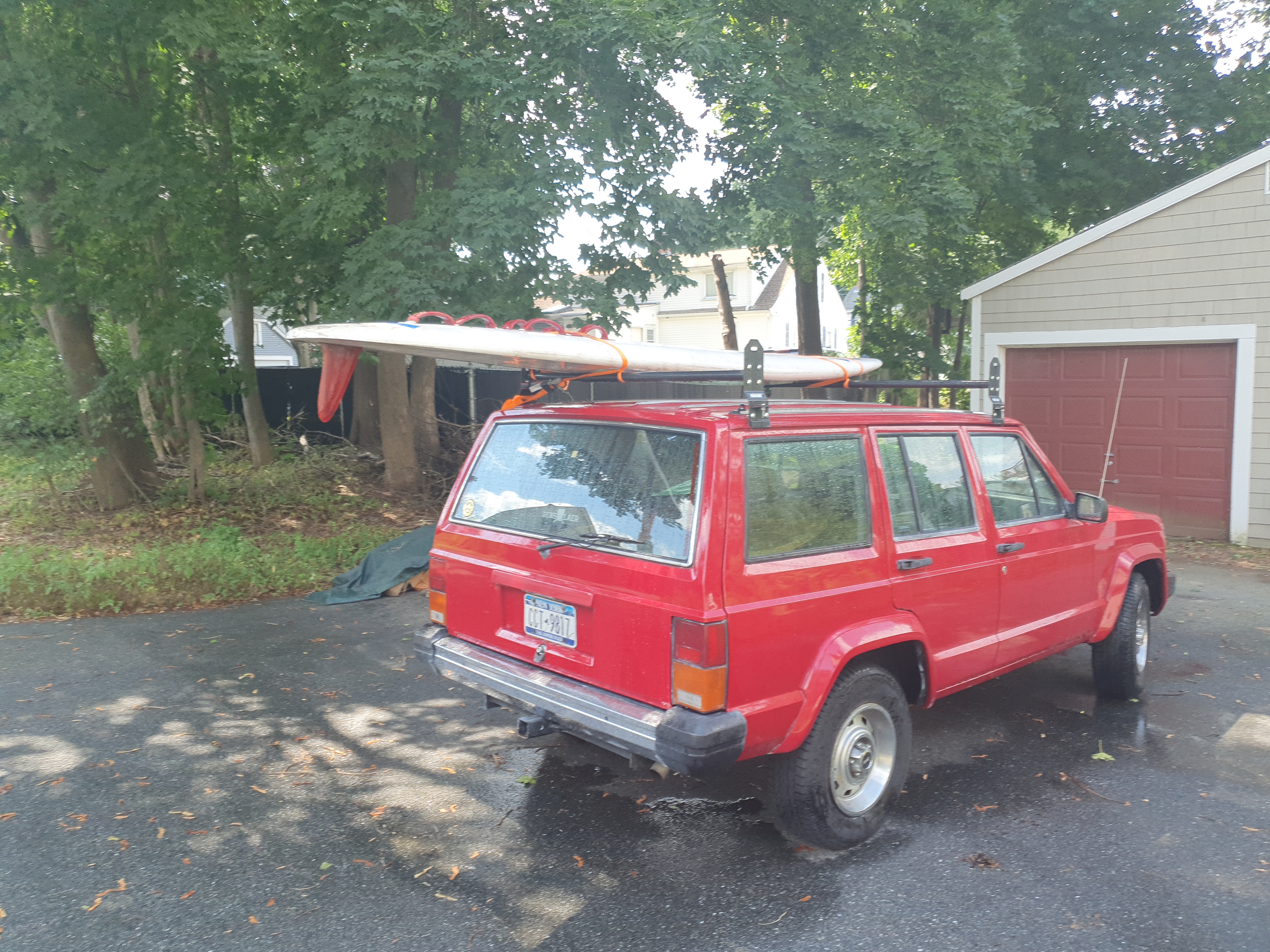
This thing is huge. The sails were in such bad shape that I did not end up keeping them. The way this is supposed to work is visible in the image below. The sail mount is nearly center-board, so all torques and forces from the wind are routed at this point, while the keel and rear fin are behind the sail mount. The user shares space with the sail and adjusts the sail and their center of balance to guide it wherever they choose. In the case of this sail board that sail mount is a penetration that goes through the board. It's intended to transfer a lot of force from the sail and seems like a great spot to connect an electric trolling motor. 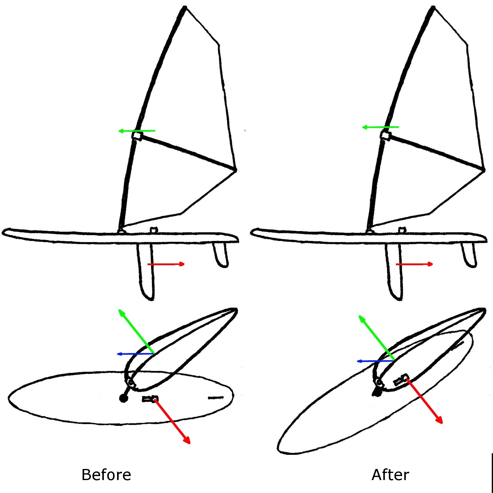
Really sleek removeable motor mountThe sail mount is a 1" wide through hole with a small plastic recess at the bottom. Comically the trolling motor is also mounted on a 1" shaft. After removing the small recess at the bottom the trolling motor assembly fits right through. 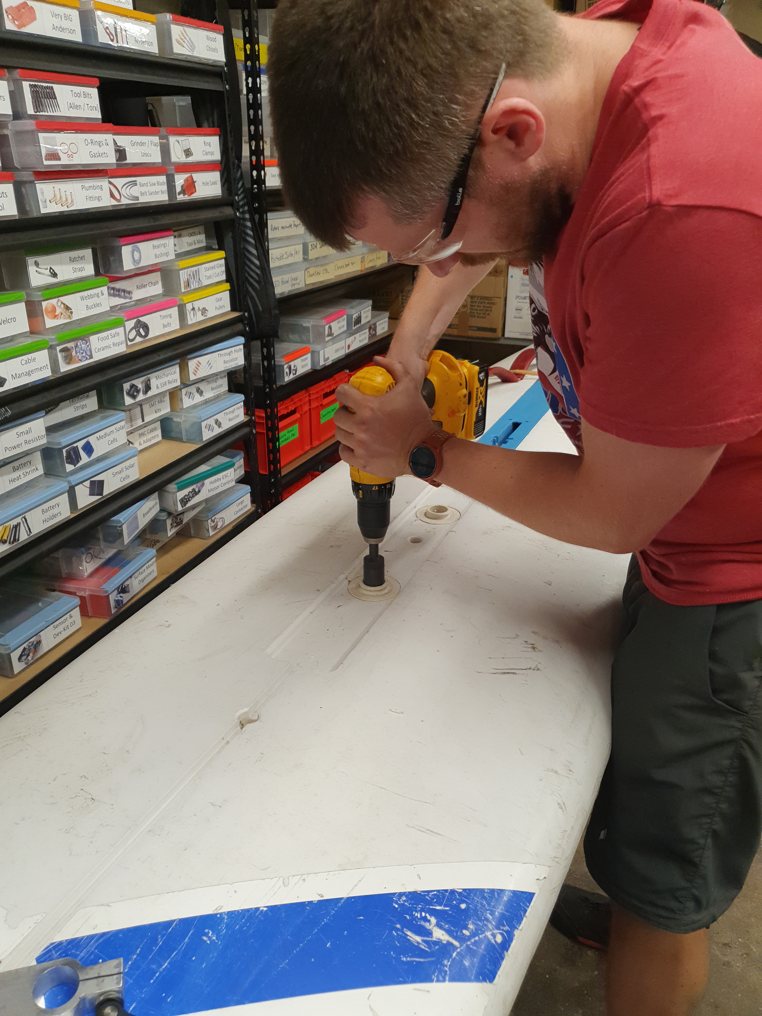
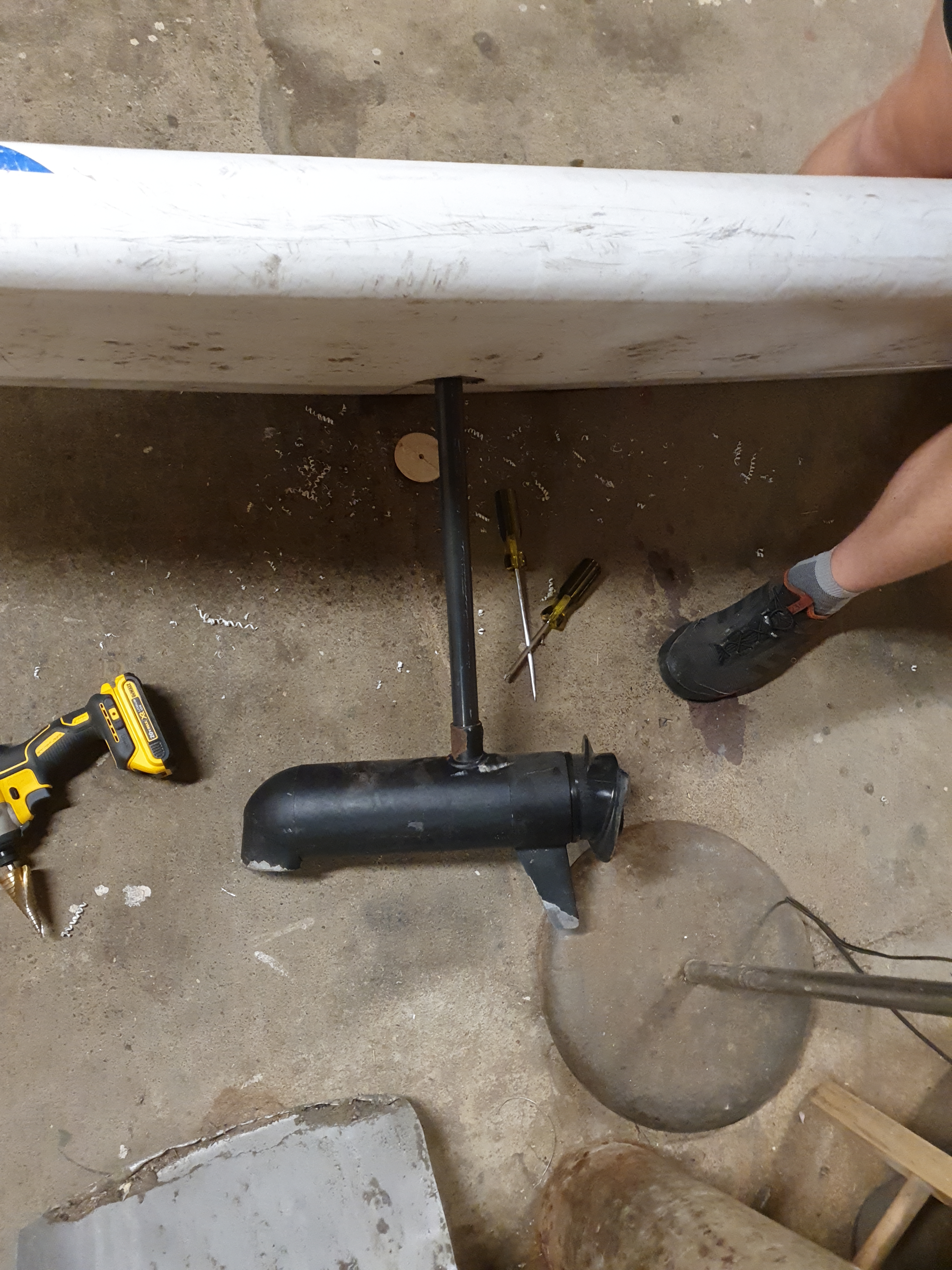
There are two mounting spots on the top of the board, a 1" through-hole and another 1" small half penetration. The board with the trolling motor installed is fairly alkward due to the motor mass, but if it was removeable, both electrically and mechanically that would be ideal. To make it easier to express what this would look like, here's a cad drawing below. 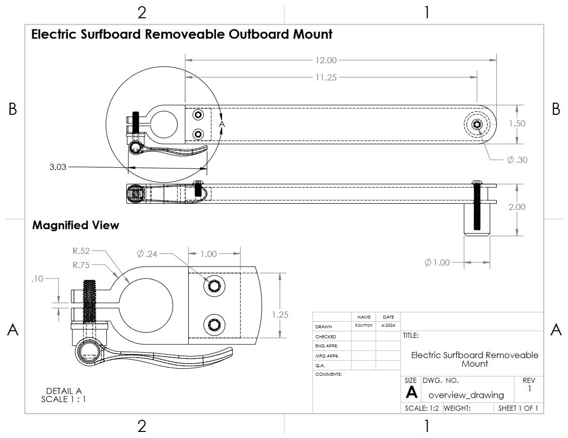
So this mount just appeared, I had some of these M6 Cam-Lock things handy but this was a bandsaw and aluminum scrap quickly built adapter using Ciaran Mechanical Magic (tm). The mount uses the rear half-inserted hole as a locating point and clamps around the trolling motor's 1" shaft for holding direction. A pipe that's the correct length to prevent the trolling motor from changing height keeps the bottom constrained. One of the excellent parts about this design is that the trolling motor can come out of the bottom when the clamp is loosened, and due to XT-90 connectors being less than 1" in diameter the whole motor assembly can get disconnected really eaisly. Cam-Locks are awesome. 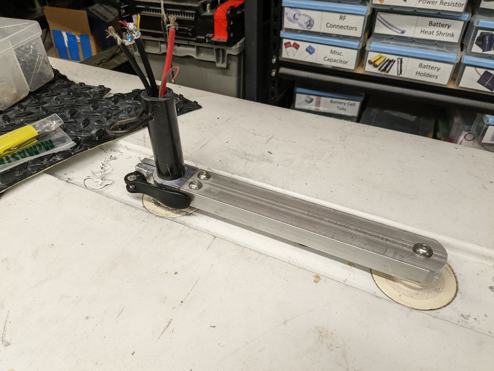
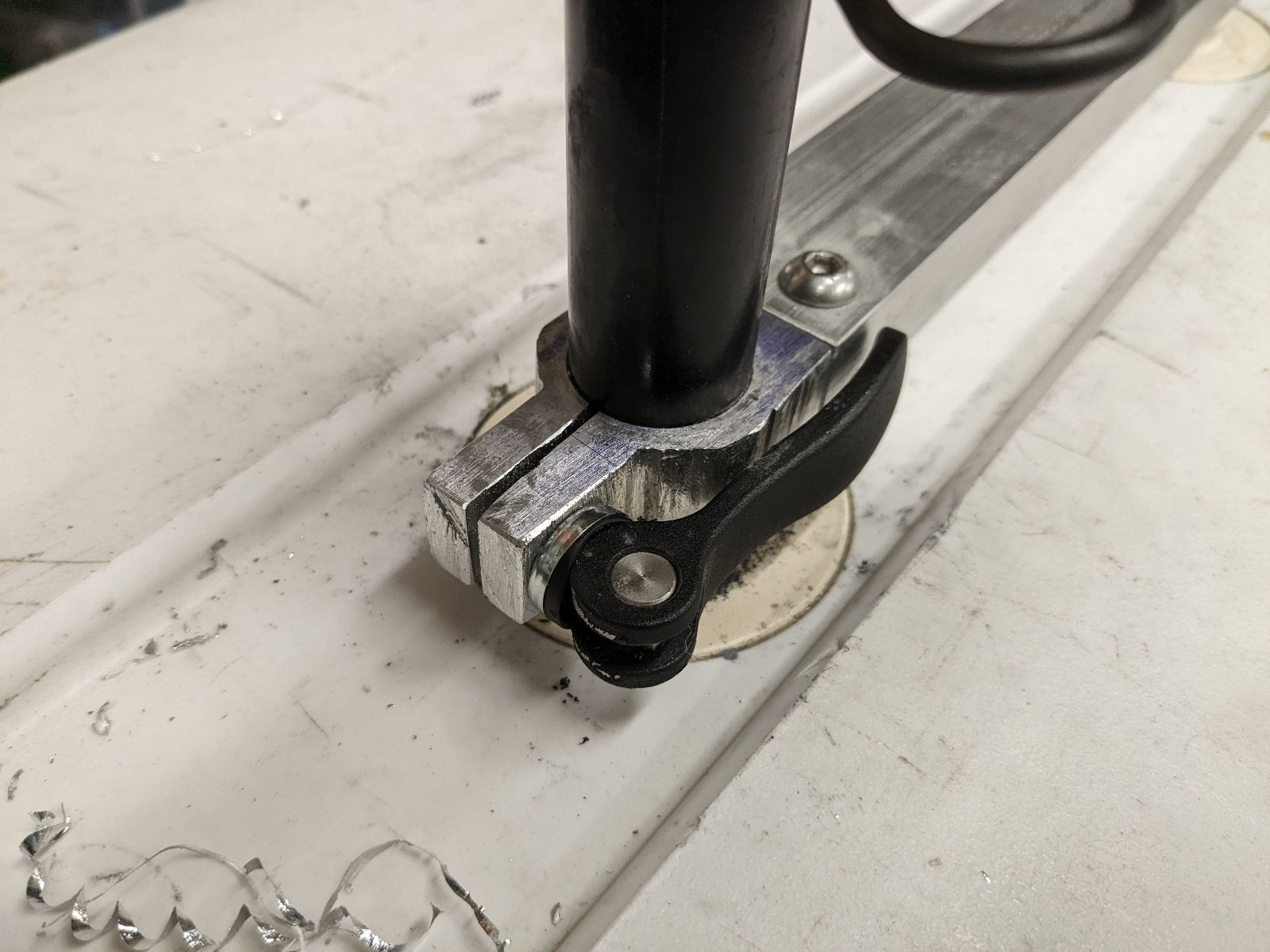
A model of this part nominally looks like this, its three components, a flexure that uses a cam-lock to clamp onto the shaft of the trolling motor, a rectangular aluminum extrusion which grabs the first part and finally an acetal / nylon post that captures the second mount on the top of the windsurfing board. A Solidworks Pack and go zip is available here [link]. I would avoid 3d printing the flexure as it's a high stress item, but if you want to give it a go here is an STL of the more complex part, use an external M6 nut instead of threading the print [link]. First Battery Pack & ControllerThe surplus trolling motor is nominally listed as a 24V motor. I had some surplus 8S lithium ion packs from the aetherial battery hookup. An 8S pack is ~32.8V charged, so some of the lower voltage kelly controllers are able to run directly from this pack. Before going out to the open water, I ran a quick capacity test on this pack using an old Hyperion 1420i balance charger. The pack came out to ~26 ah, or roughly 800 watt hours. This is plenty for zooming around for a half hour and given that this pack is intended for high discharge rates I did not have to really worry about thermals. I'm fairly certain this pack is an 8S sonata module. 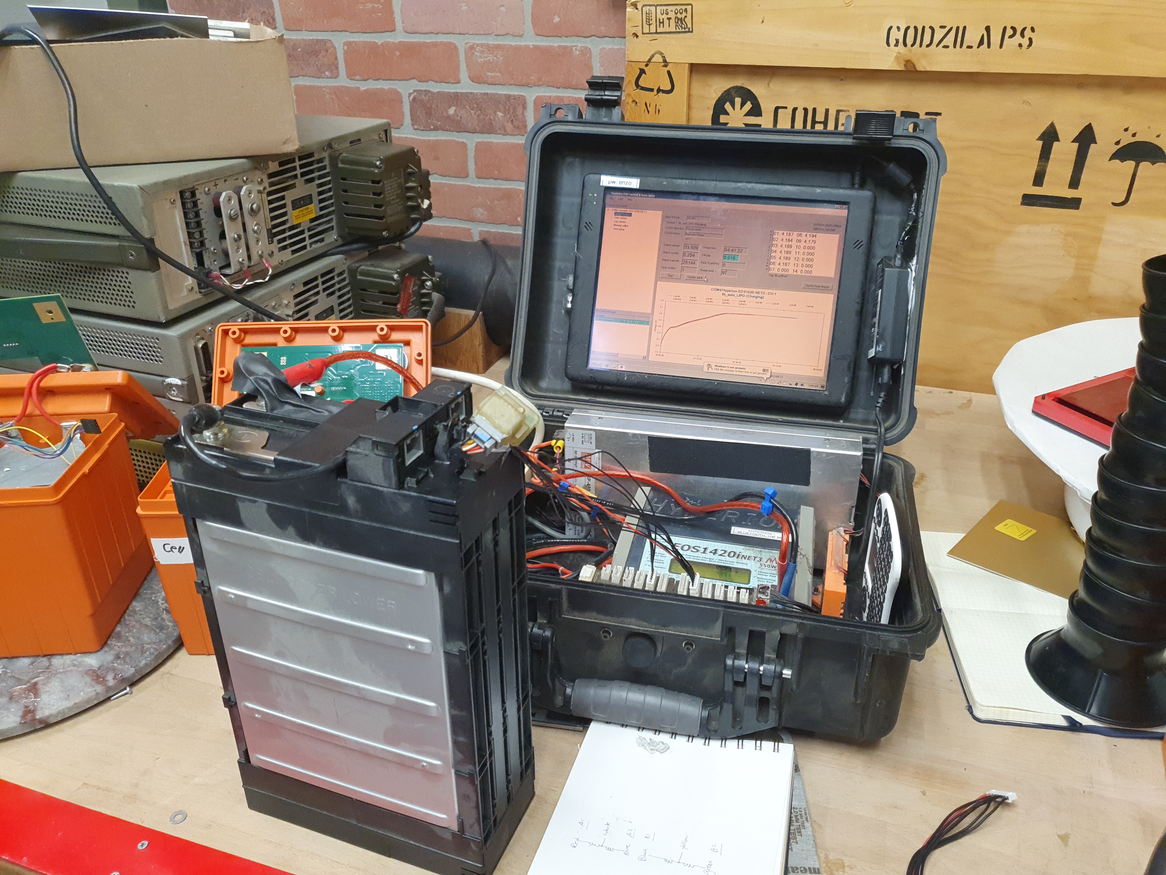
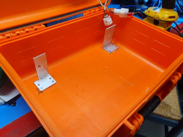
This pack also conviently fits in the harbor freight pelican case clone remarkably well. To constrain the pack, there were a few options but allowing the pack to be removeable without having too many holes in the waterproof case is preferred. 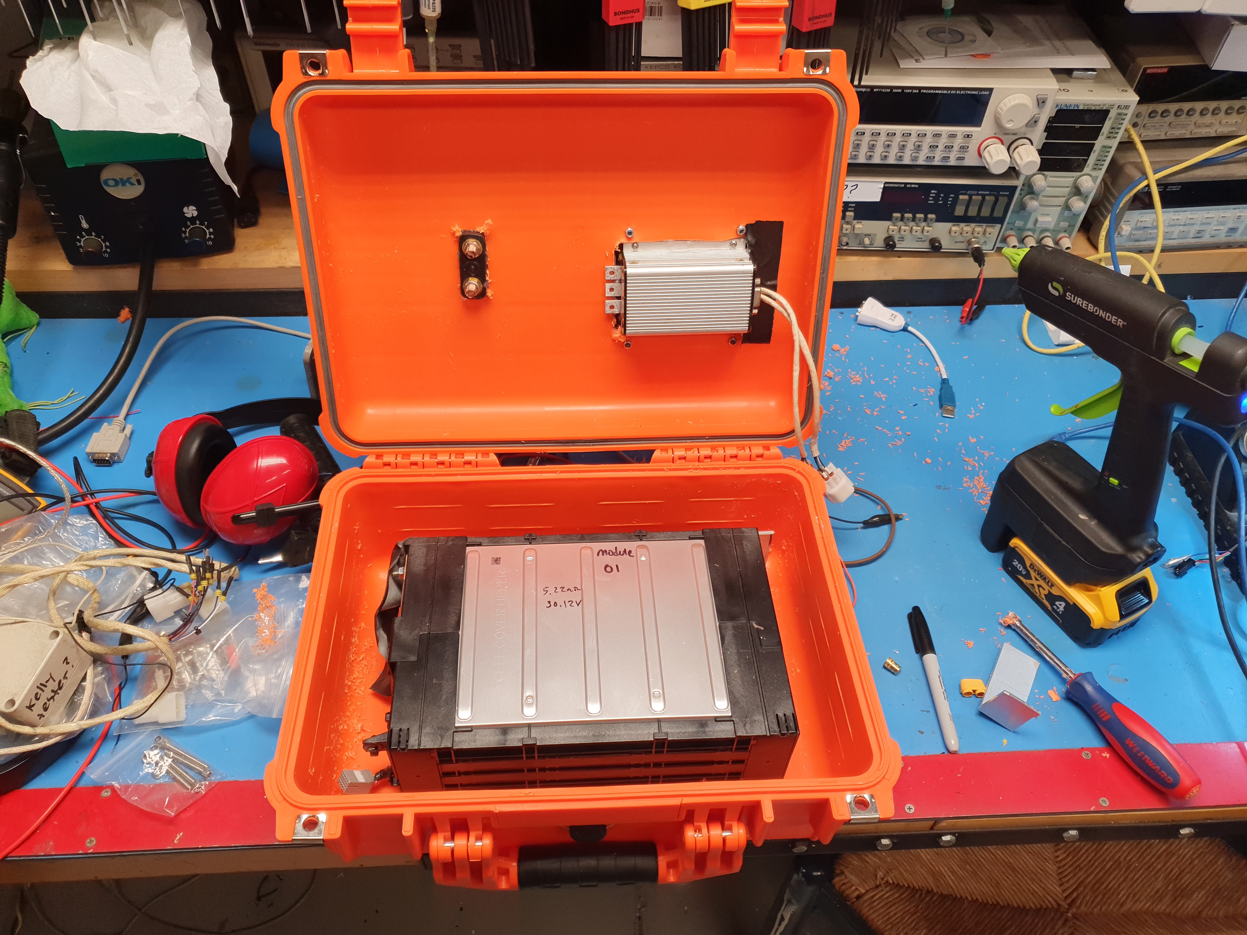
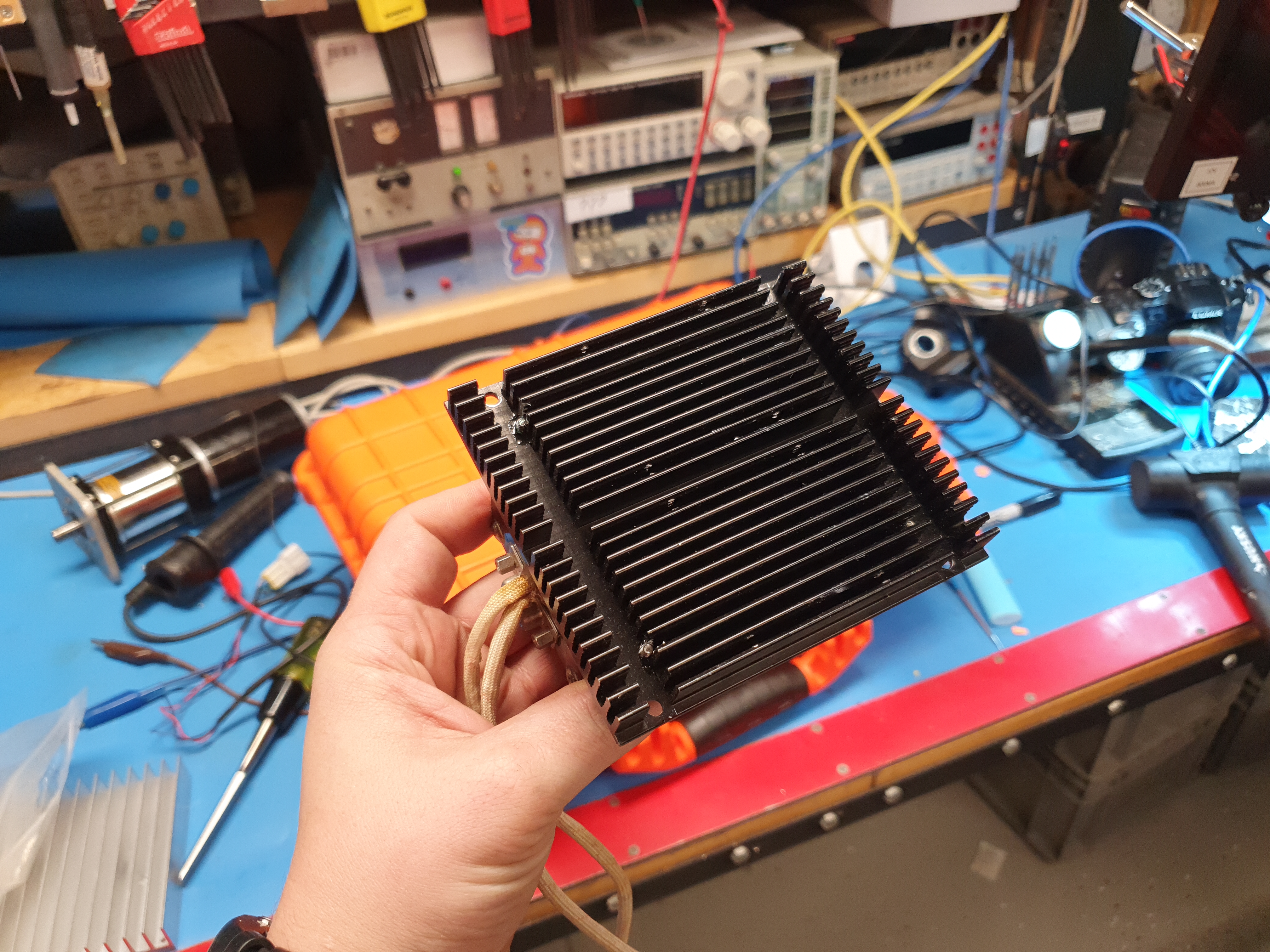
Mounting the motor controllerOne of the issues with having everything mounted inside a sealed case is thermals. There's no easy way to get the heat out. The main source for heat is the motor controller itself. To get around this issue I opted for a flush mount heatsink attached to the case and bolted in place. Because the heatsink is mechanically larger than the controller its possible to fit sealant around the perimiter of the heatsink and then mechanically bolt it to the plastic case. 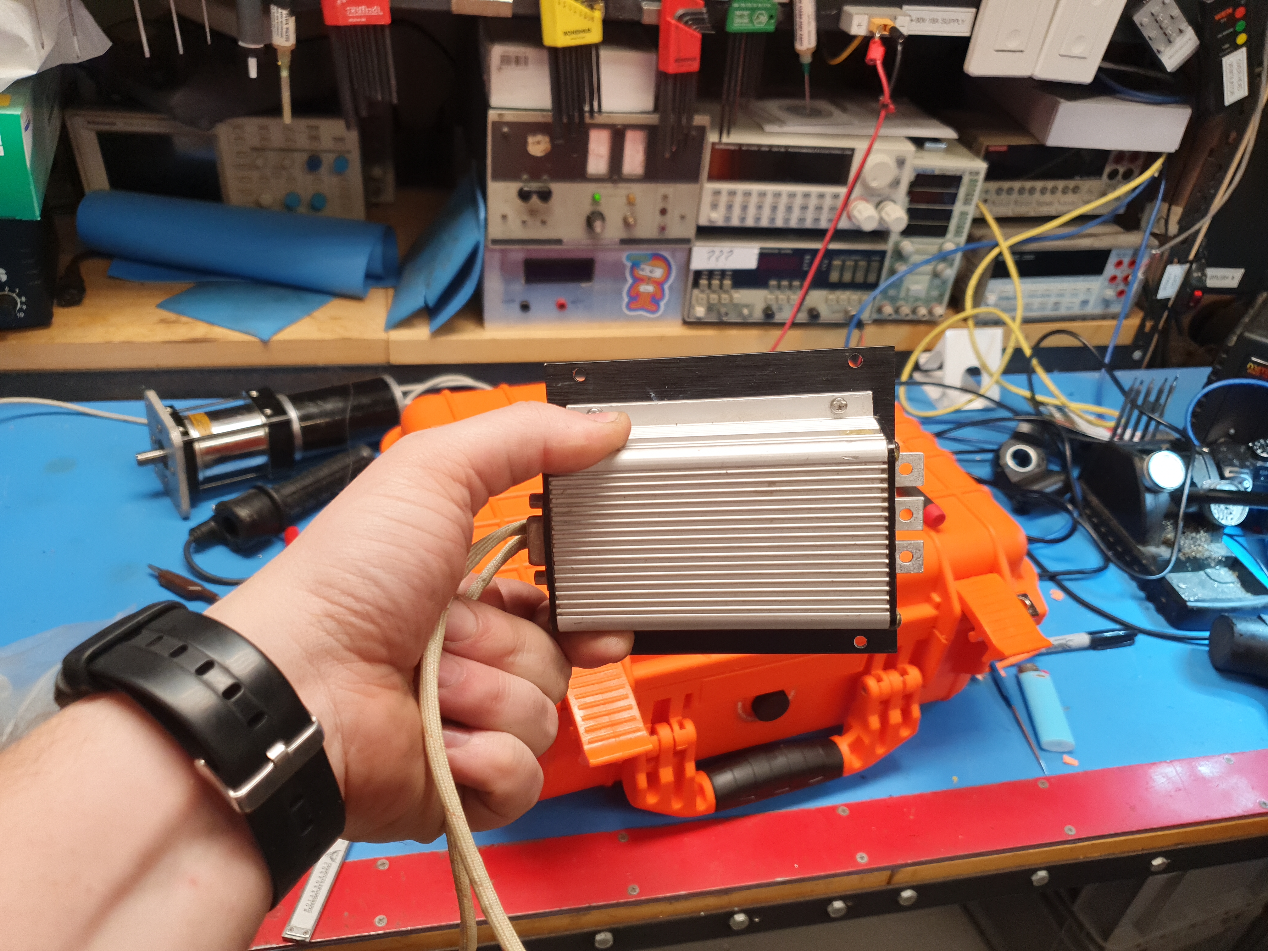
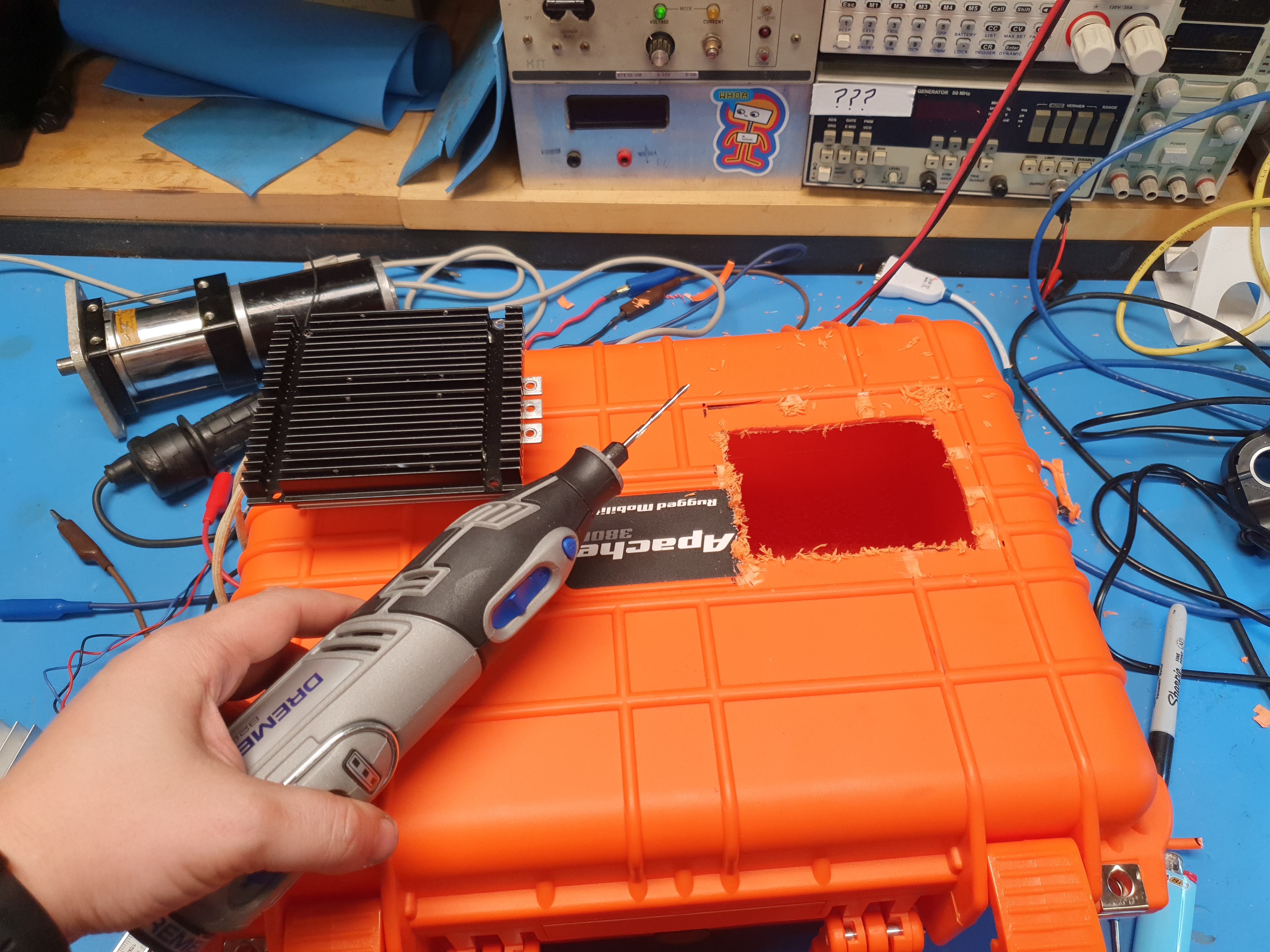
This required a weird sized hole to be made. To allow a flat mate between the heatsink and the case I needed to remove the plastic ribs that are part of the case. Initially i had some terrible ideas of using a soldering iron with a knife edge, but then I was reminded that chisels exist. Some quick chiseling later and there's a flat surface to silicone the heatsink assembly to. next up i traced an outline and used a cordless dremel to cut out a square hole that just fits the kelly controller. Given that the case was some ABS-Nylon blend, i abraded the surface with some sandpaper before applying a layer of silicone. 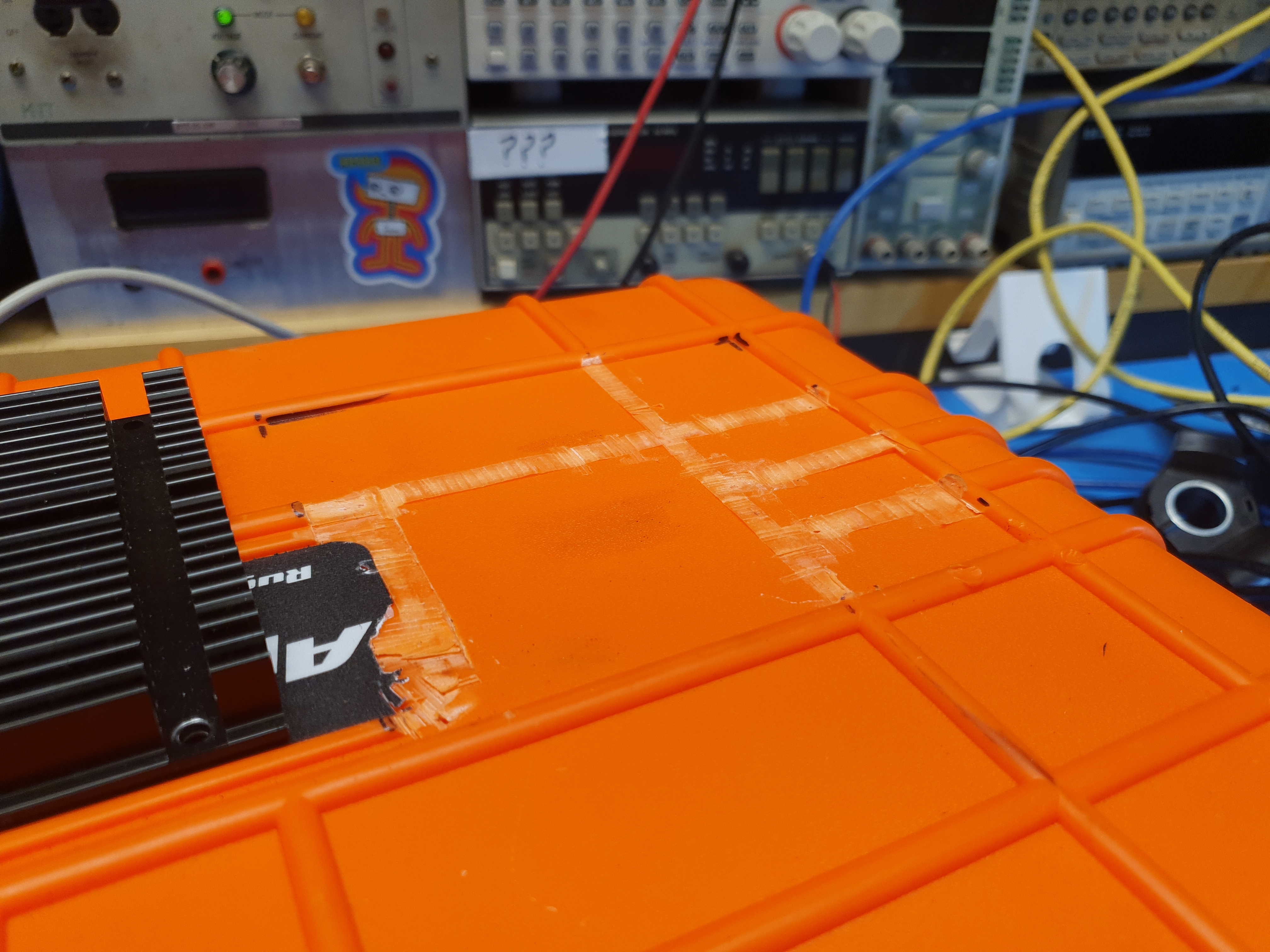
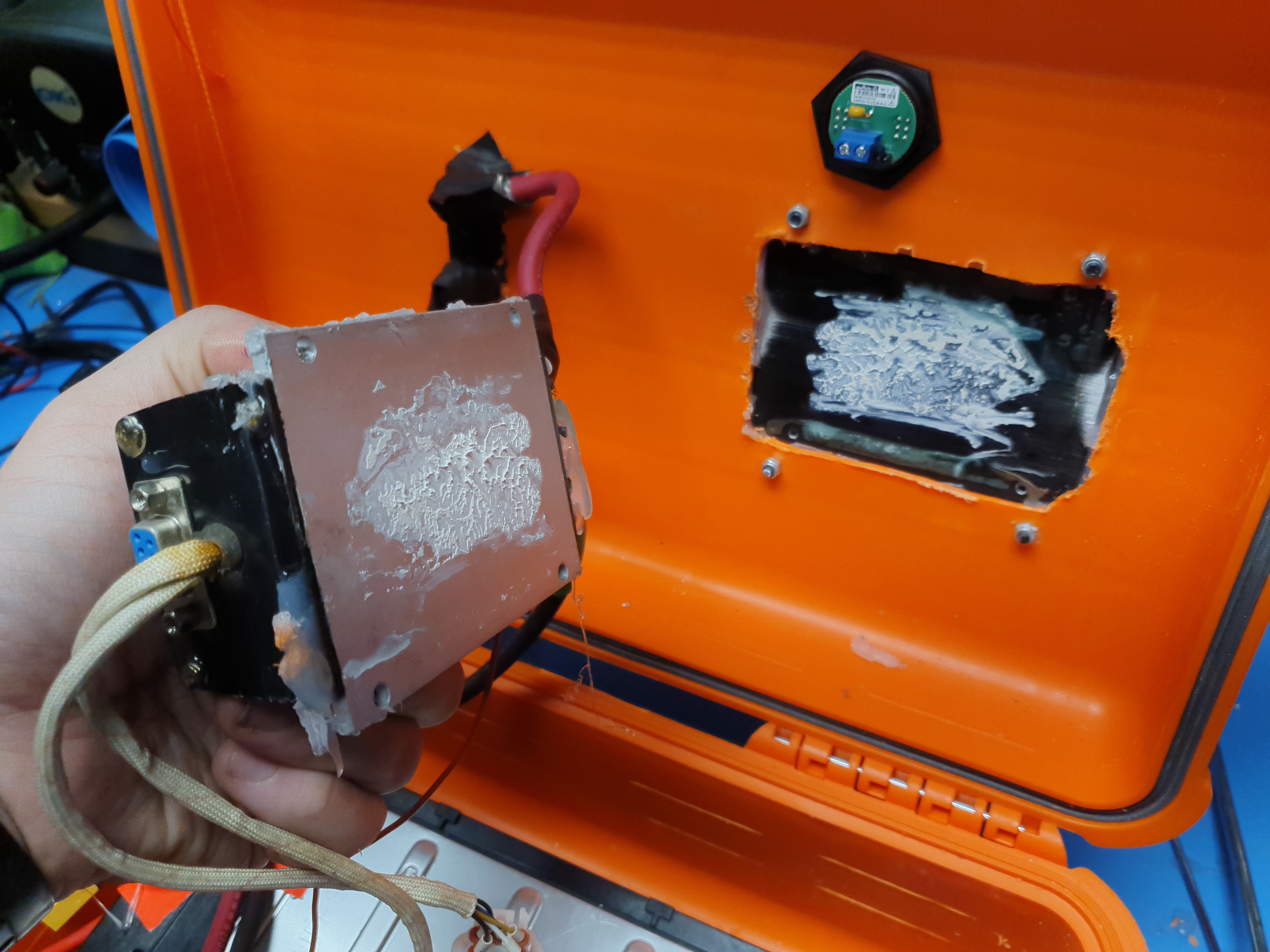
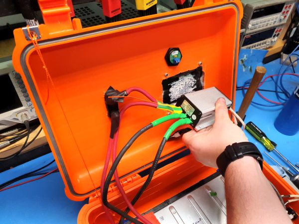
The layout ended up looking fairly reasonable. The heatsink is bolted to the case, with RTV sealant wrapped around the heatsink-to-case mate. The controller itself is screwed into the heatsink itself with a thin layer of heatsink compound helping keep the thermal interface conductive. You'll notice a small voltmeter shown added in. It turns out there are very few waterproof voltage displays and I ended up going for this model from digikey [link]. Having voltage displayed outside the case is convienient for basic diaognostics. 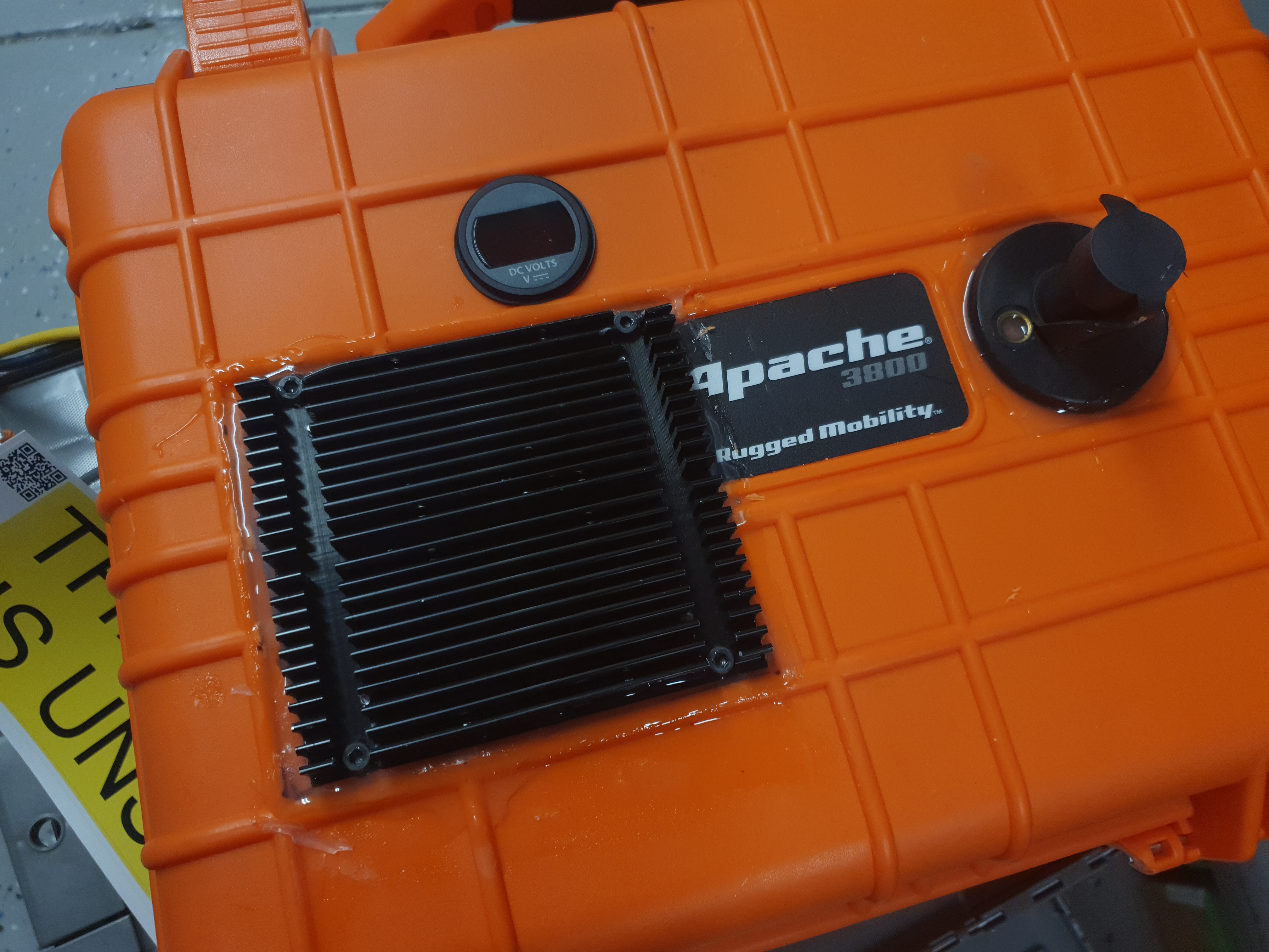
Finally this is the version 1 setup, an internal 8S Lithium Ion battery module, a brushed 100A (peak) kelly controller a disconnect switch an error indicator and a voltage display. Pre-charge is a manual process for startup, which is a little hard to explain to a new user, but it helps prevent abusing the DC brush controller capacitors from inrush current. 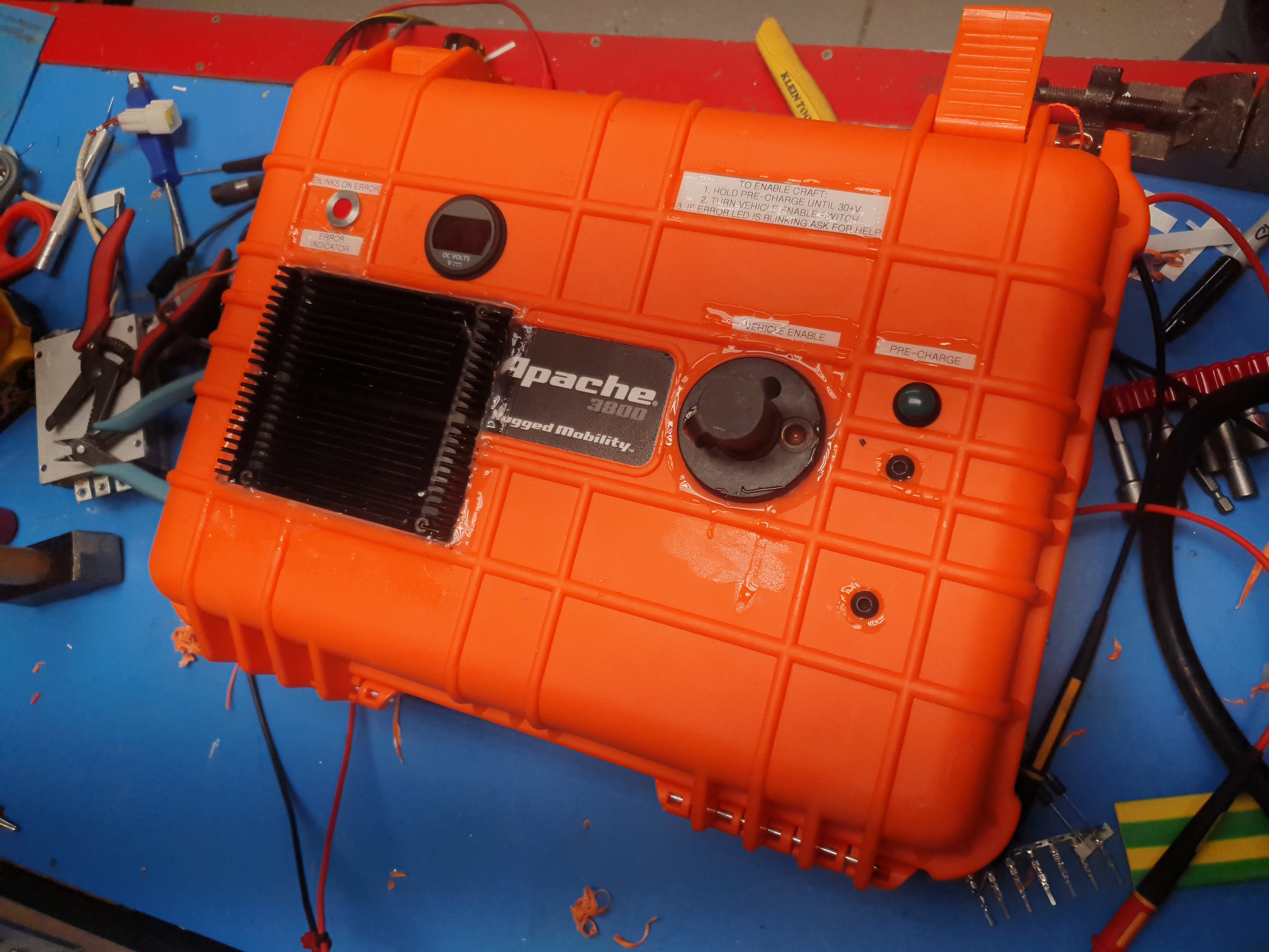
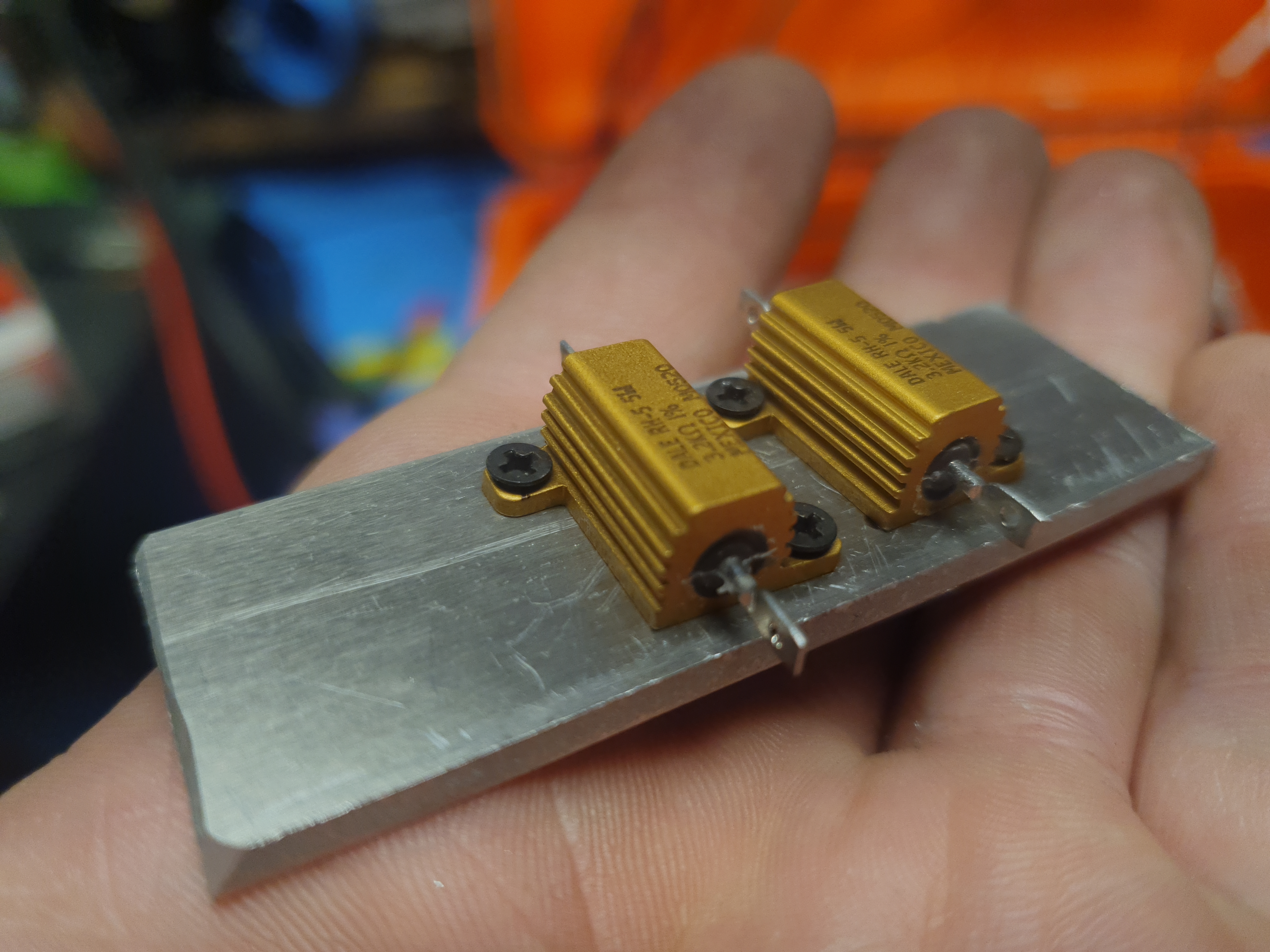
There were some parts about this 'prototype'. This particular kelly controller wants an in-line serial adapter gadget, which was somewhat hard to find. This is no longer really necessary for the modern controllers but this legacy one that i had from a previous project did need this adapter. It's an active adapter with internal hardware, not just a pin-switcher. For pre-charge I also did not have a huge assortment of power resistors so I ended up with two of these 3K resistors in parallel, which as it turned out, was still way too high of a value. 
Making the 'waterproof' hand controllerI wanted a quick 'test' throttle and given that there was no chance that a hall-throttle would survive constant submersion in-water, I came up with a plot to re-use a remote camera shutter print as a throttle. You may recognize this print from this project. It's the same print with some small changes to the pushbutton text and also changes the wire termination to use a cable gland. This is sized to 'just' fit the nut internal to the cable gland so no tool is required to tension it in place. Instead of having continuously variable electrically isolated throttle, this is kind of the opposite, internal to the case / controller there is a pull-down resistor, such that if the 'throttle' gets disconnected it fail-safes in the off condition. 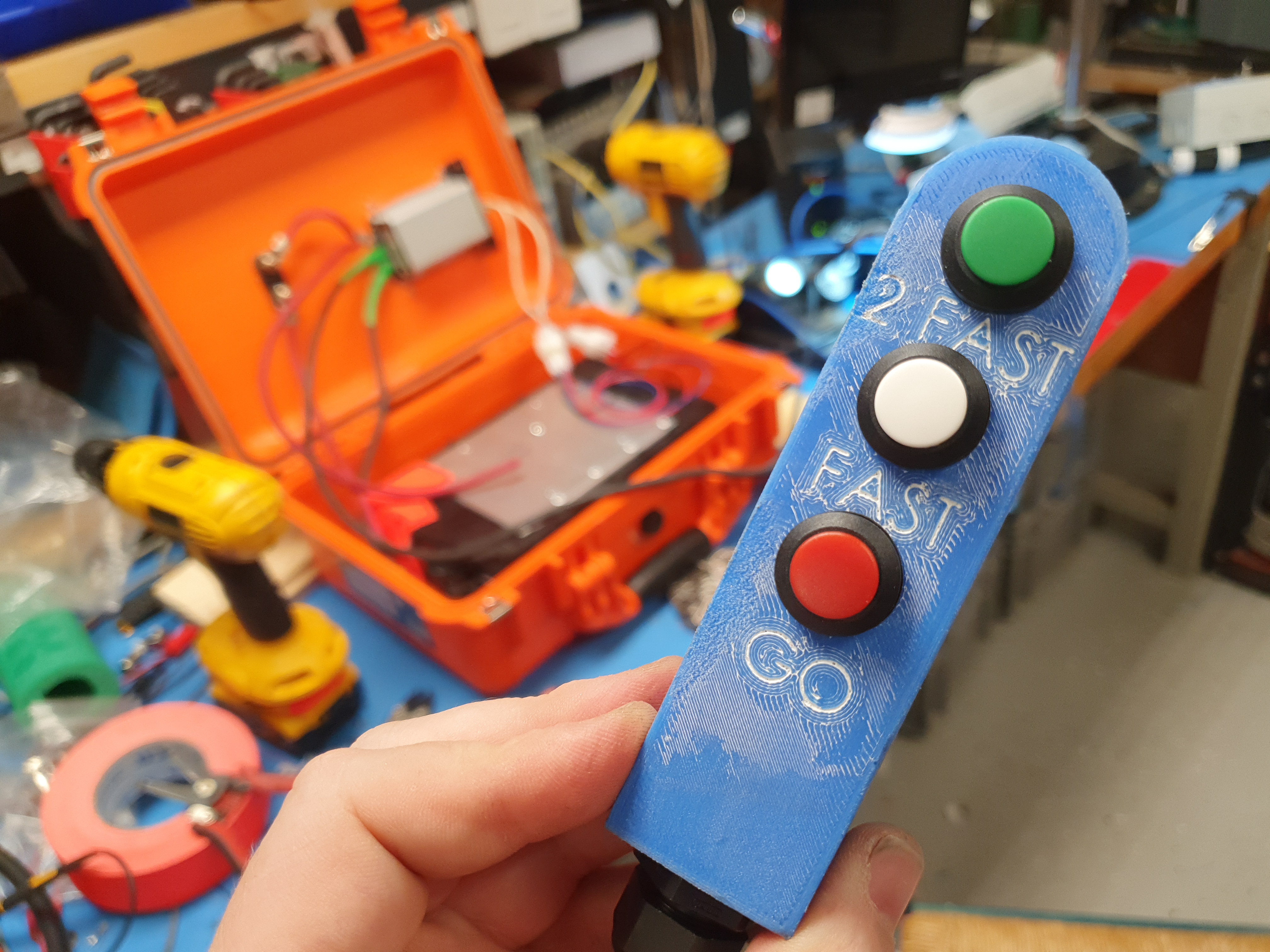
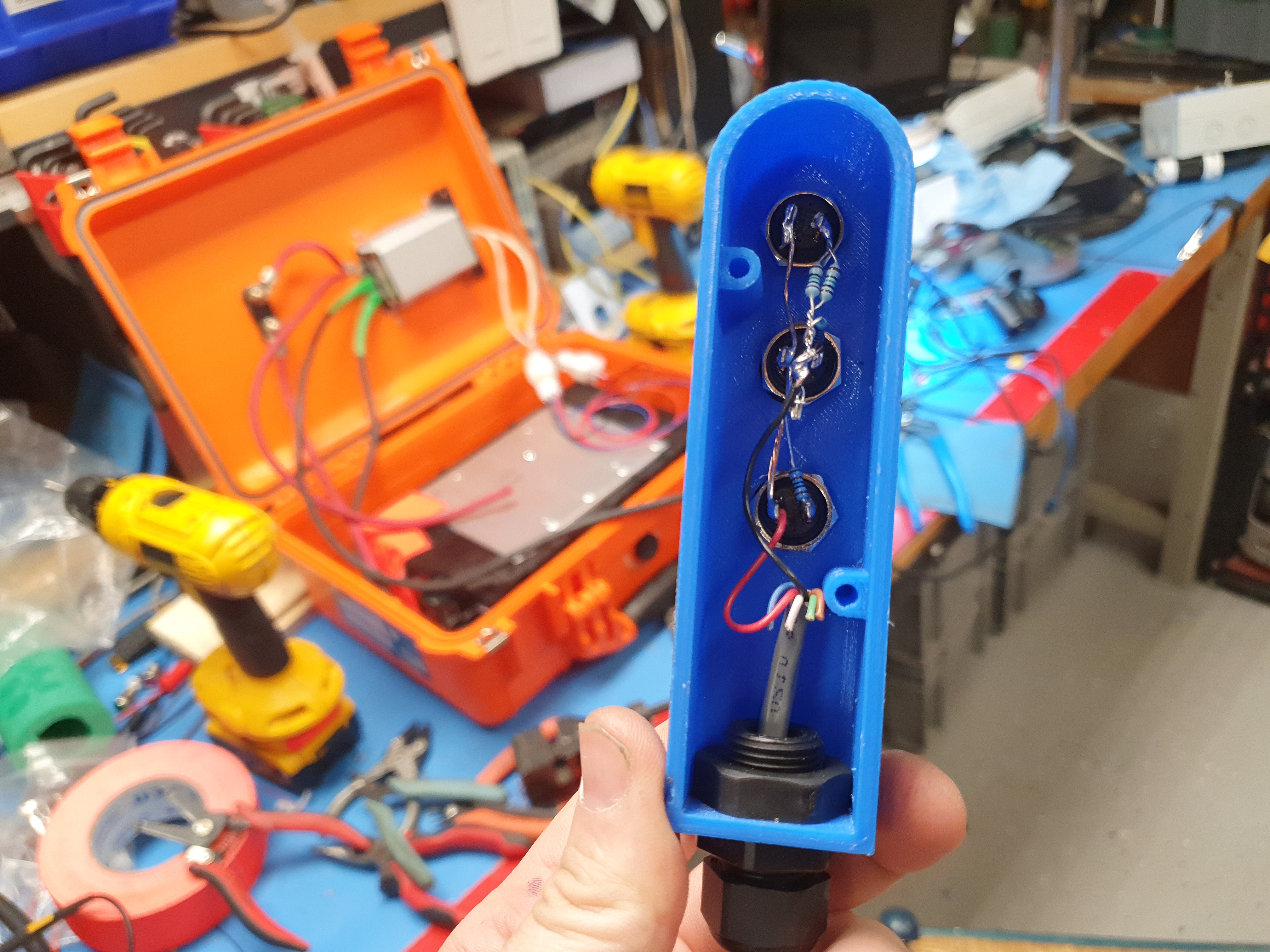
Making the controller waterproof was another issue. After testing the resistor values a half dozen times and making sure the cable gland clamped around the cable sufficiently the back of the assembly was potted in silicone. These buttons are waterproof but I always take that with a bit of salt. that was a terribe pun. The next step was to figure out how to make it float. initially the plan was to use a pool noodle but it seemed to be the wrong form factor. I hiked over to target and found this thing: 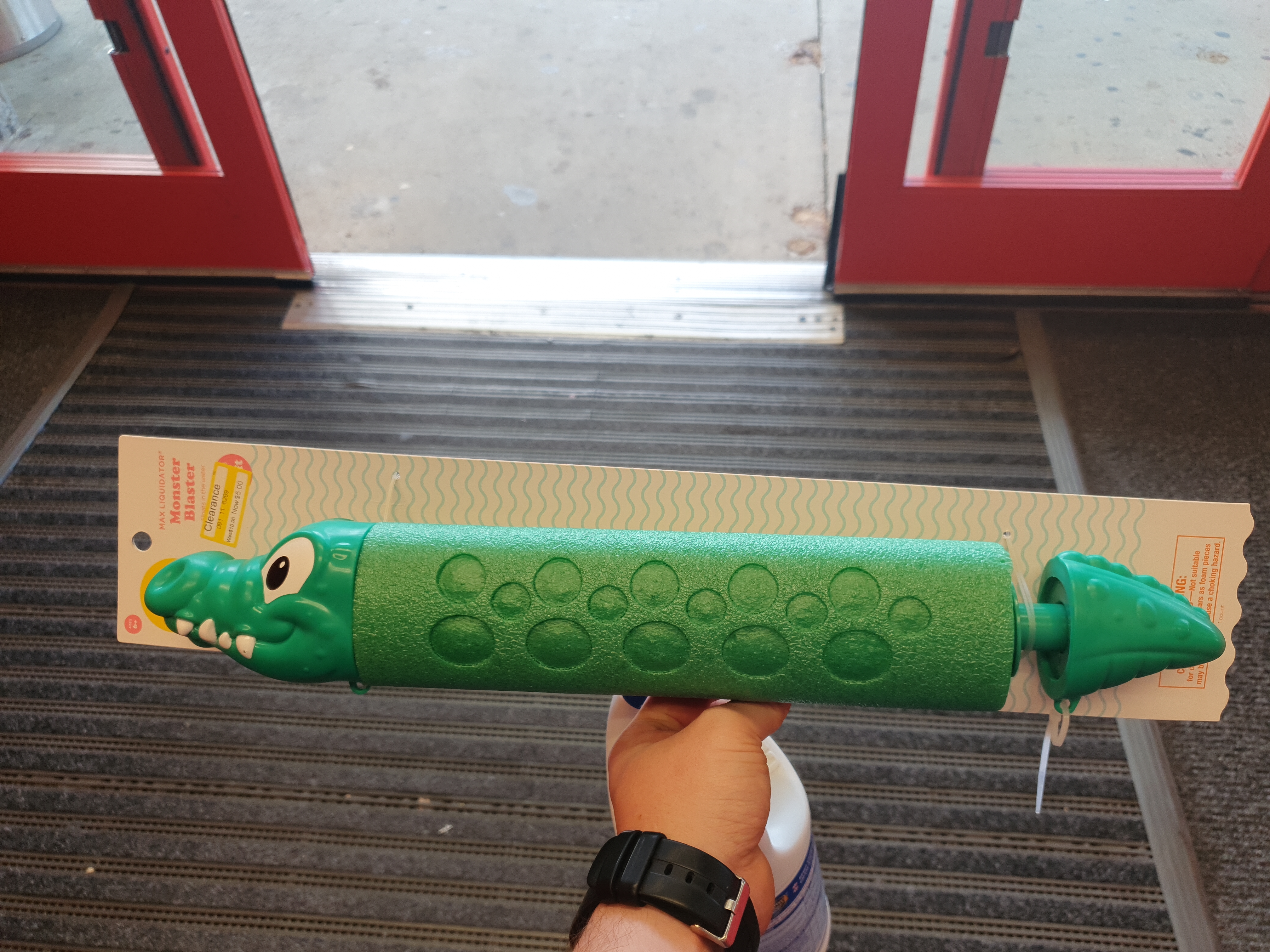
Its some kind of crocodile water gun, but the green insulation is perfect for acting as a floatation add-on. It felt silly to completley destroy this thing to extract its foamy outside, but for whatever reason pool-noodles were not available anywhere. In time for some local summertime testing, a custom bumper sticker. Not sure why this made me so happy but it is so incredibly accurate to describe using this surfboard. It's so counter intuitive to use. 
First test ridesAfter a lot of fiddling i finally got up on the board, on this test I was holding down 'green' or the fastest speed, which does look fairly quick but is somewhat distorted by the position of the GoPro camera close to the ground. There were many bailing off the board events at least for me, Ciarian somehow quickly figured out how to get the board to behave. Ok the first rides were a bit rough, I managed to not only fall off but also flip the board around, putting the whole electronics assembly underwater. Miraculously the waterproof case did a great job keeping everything dry. Also hot damn the GoPro 8 did a great job capturing this footage. After a bit of trial and error the board was ride-able, but a bit too tame. It accelerated hard but the top speed was not particularly speedy. I didnt phone-gps speed test as, I was likely going to loose it in the drink. Best guess the speed would have been 3-4 miles per hour which is a great first pass but that is barely faster than a swimmer sprinting. The first testing went well but it was time for some more speed. This trolling motor is intended to keep a large watercraft in a fixed positon, or to slowly put it around, while the goal of this surfboard is to provide a pile of thrust at a reasonable speed on a lightweight watercraft. There's two ways to increase the vessel speed, change the propeller pitch, which is somewhat difficult, or increase the battery voltage. Given that I'm a battery person you may have already figured out the quick path forward.
I know the first think you're thinking, But Dane, the motor may only be rated for 24V operation! DC brush motors are curious, the limiting factor on a brush motor is the brushes. If the brushes see too much current they thermally degrade, wear quicker and can damage the copper contactor pads. We're not operating this motor in voltage mode, we're operating in current mode, limiting the current to 40A, which is its actual rating, from the manual. If we hit the current limit of 40A at 24V then that is the motor limit, however, if, due to propeller pitch or the crafts integrated speed we hit that limit closer to 40V, unless the motor mechanicals start to degrade, we're likely within the operating envelope of this motor.
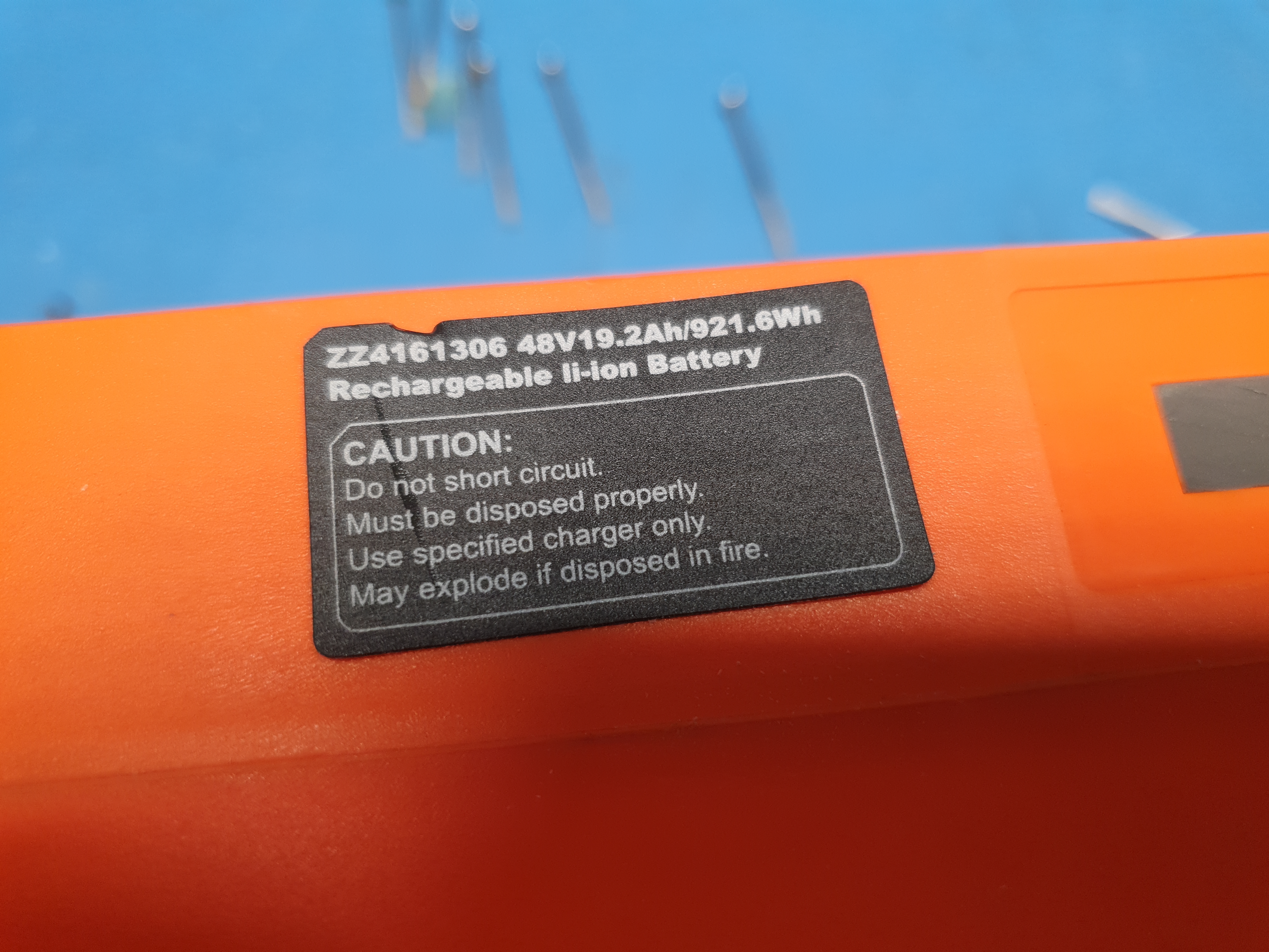
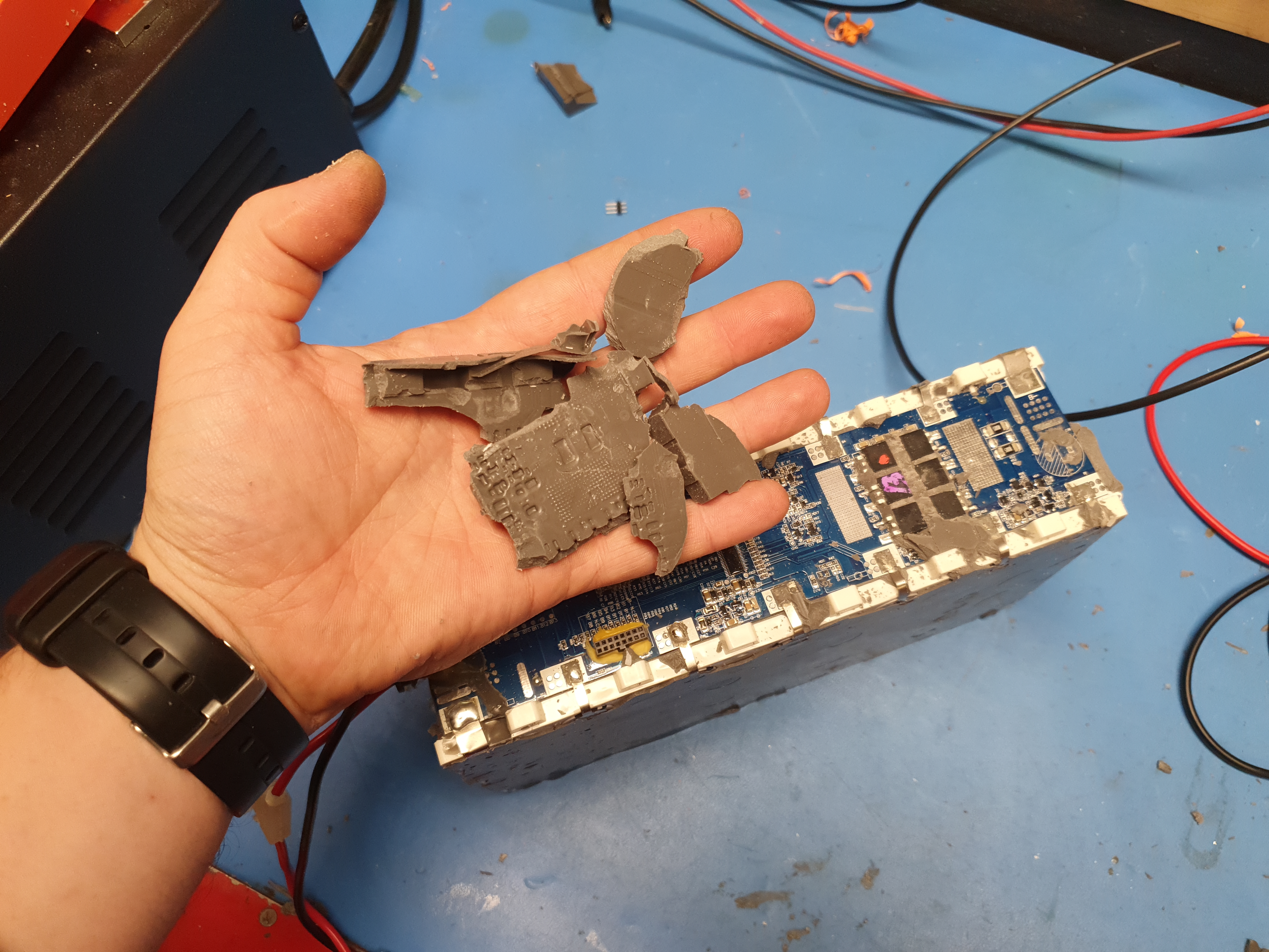
Motor test at 36VWith the trolling motor mounted using the superluminarlly fast assembled adapter from Ciaran, we did a super simple 36V spool up test using some K2 12V7 style battery packs. Given that this was just open air, and the motor was not submerged with coolant this was just a quick test to confirm it was fine running at 36V nominal. Upgrading the battery packThis battery pack was a battery-hookup mystery cube. The actual part number is ZZ4161306 48V 19.2Ah Rechargeable Li-ion battery from Greenway. I couldnt find an exact spec sheet for this pack, and there was no real indication as to what the BMS was rated to. If there was a simple "40A discharge, 10A charge" rating on the pack I would be good to go. It's going to be hard to figure out what exactly is going on if the battery management board disables on discharge overcurrent. Let's open up the pack and see what's going on inside. 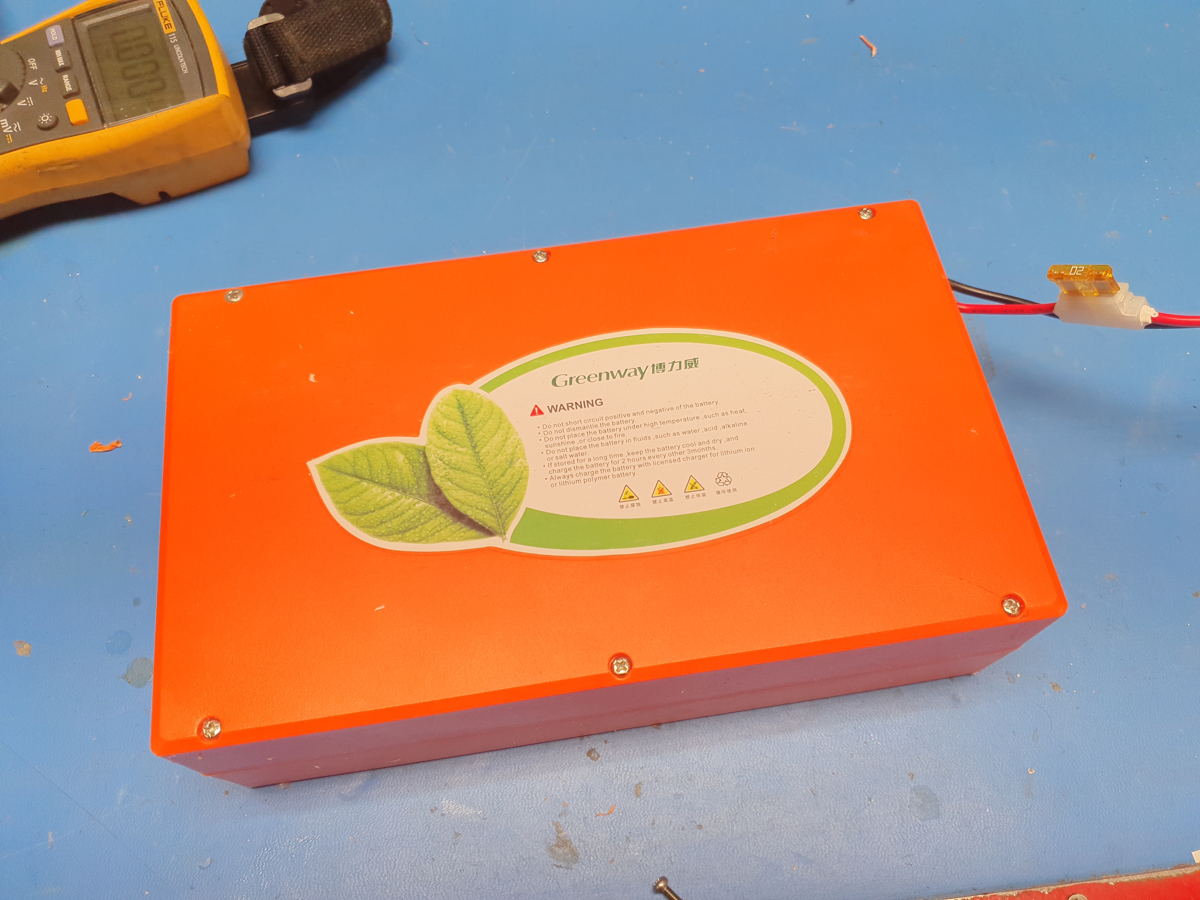
The pack is remarkably well sealed. This is really well done. We get a solid pcb with a cell level measurment breakout that's sealed behind a rubber gasket. I have no idea what this gray solastic sealing is made of but it is perfect. It's remakably removeable but also makes a really good seal to the board level components. 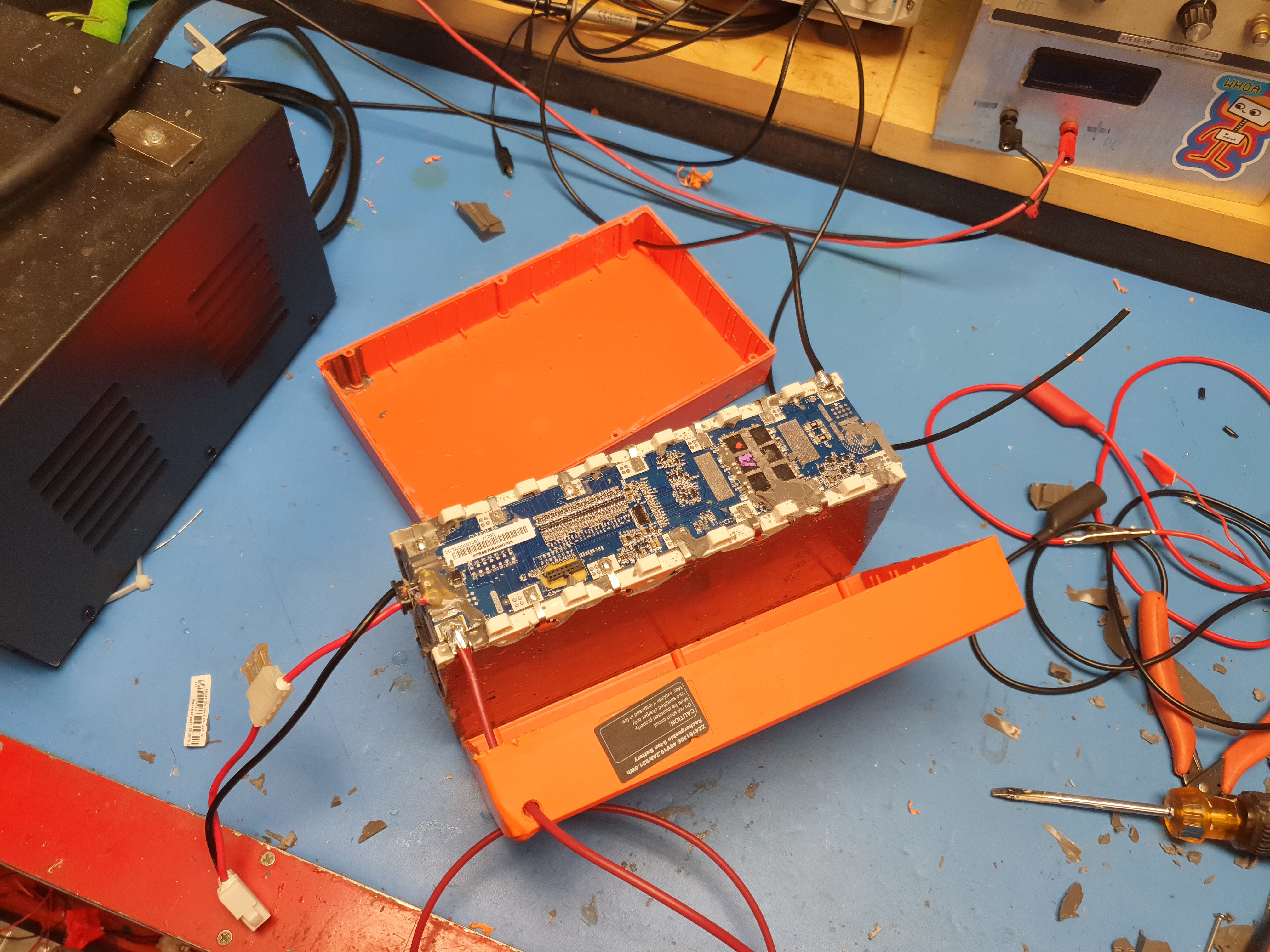
Lets zoom in a bit and find out more about this BMS. We have Charge / Discharge fets with model # CRSS058N mosfet [link]. These are 85V 120A 4.6mOhm N-Channel mosfets. It's odd to see TO-263 instead of TO-263-5 for high current operation, but either way these are fairly reasonable fets. We have three in parallel for over voltage protection as well as three in parallel for undervoltage protection. This is great, aside from the lack of thermal path out of the sealed pack. 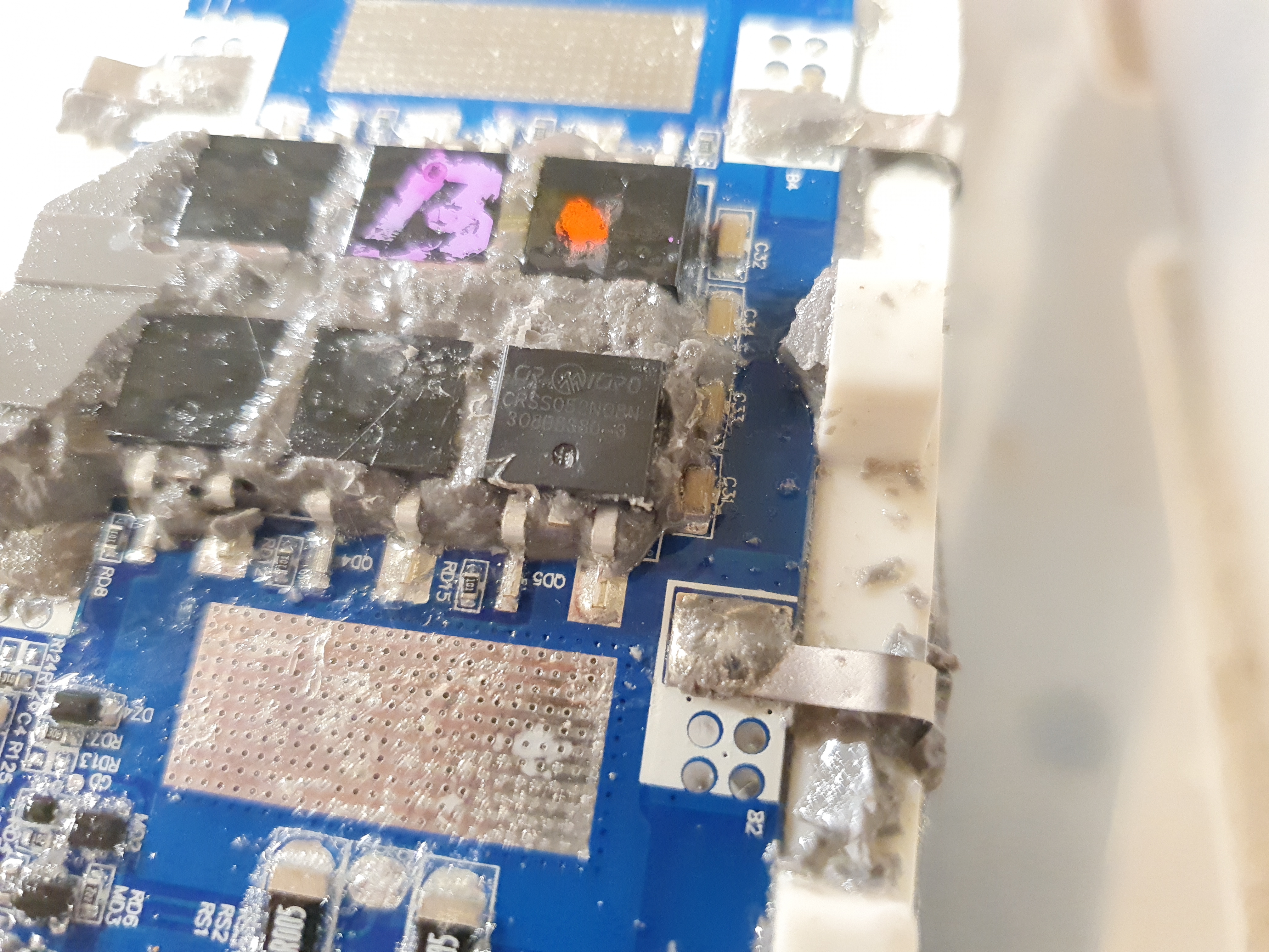
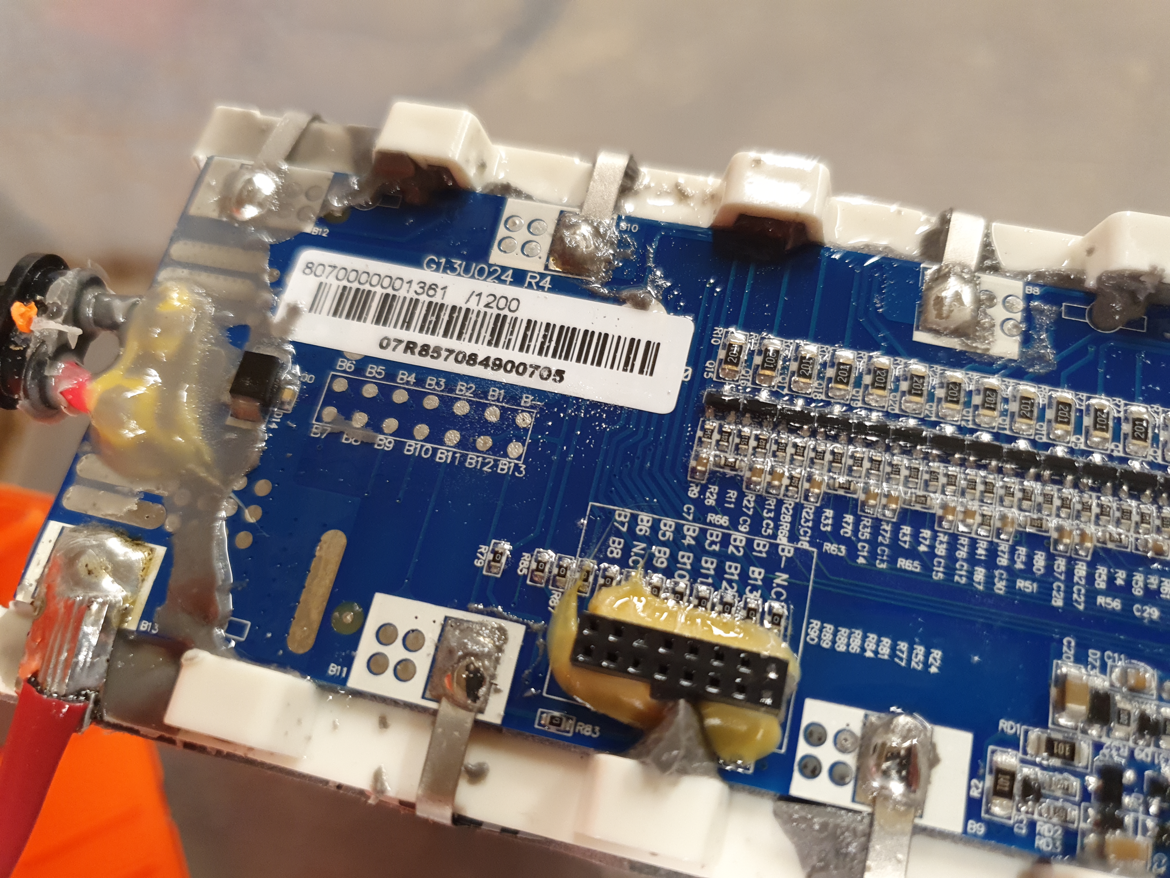
The actual analog front end ic and microcontroller is likely under-board, which would require removing a lot of cell weld tabs as well as the current carrying weldstraps. I did a mild pack discharge, using a hyperion 1420i, grabbing the cell voltages, but using the pack level voltage to see when the pack undervoltage tripped. I did notice that it did undervoltage cut-out when any cell hit 3.0V. Next i used the same setup to charge the pack to 4.25V / cell. Setting the pack as HV will allow us to determine if the cell level OVP functions. I'm happy to report the BMS opened up the pack when the highest cell hit 4.15V. We have a verified working BMS. We do not know what the limits of the BMS are but we very much know that it's OVP functions, so using it to regulate and limit charging is perfect. We can somewhat cheat regarding using this pack for surfboard activities, the Kelly Controller does have an undervoltage threshold and error indicator. Bypassing the BMS for discharge is fairly easy on this pack, by soldering a pack level + and - to the weldstrap and terminating it to an output connector and an in-line fuse.
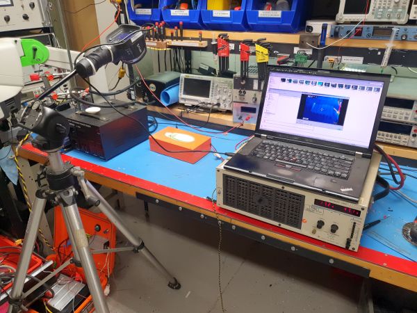
Battery Pack ThermalsHow well would this pack hold up for discharge testing though? Marine gadgets are significantly different than a scooter or e-bike. A scooter can pull fairly high startup current but eventiually, on flat ground, it runs out of acceleration and as a result the battery current drops off. Marine applications result in constant loading, the user can hit the go button and continuously discharge the pack, and like most marine gadgets, the surfboard itself will pull quite a bit. With our modified module, we can discharge directly from the pack and as a result the heating internally is caused only by the cells themselves. We want to keep track of the cell temperatures and use that to define our operating limit. For this first pass test, we're using a thermal camera observing the pack from the outside and an electronic load capable of running a 20A discharge, or roughly 1kw constantly. To record the thermal buildup on the battery pack I used a modified Flir E4, mounted as a usb video device and recorded with VLC. This is an extremely alkward setup in comparison to modern phone thermal modules, the flir auto calibrates periodically and changes its color scale with a mind somewhat of its own. Either way here's nearly 50 minutes of thermal buildup of a 19ah module discharging at 20A into an electronic load. Updated Controller: More VoltsTo upgrade to a 13s Lithium Ion pack, we needed to upgrade the dc brush controller. Fortunatley Kelly controls sells motor controlers in the exact same form factor still, so we get an upgrade to supporting 50+V at 100A peak in the same form factor. 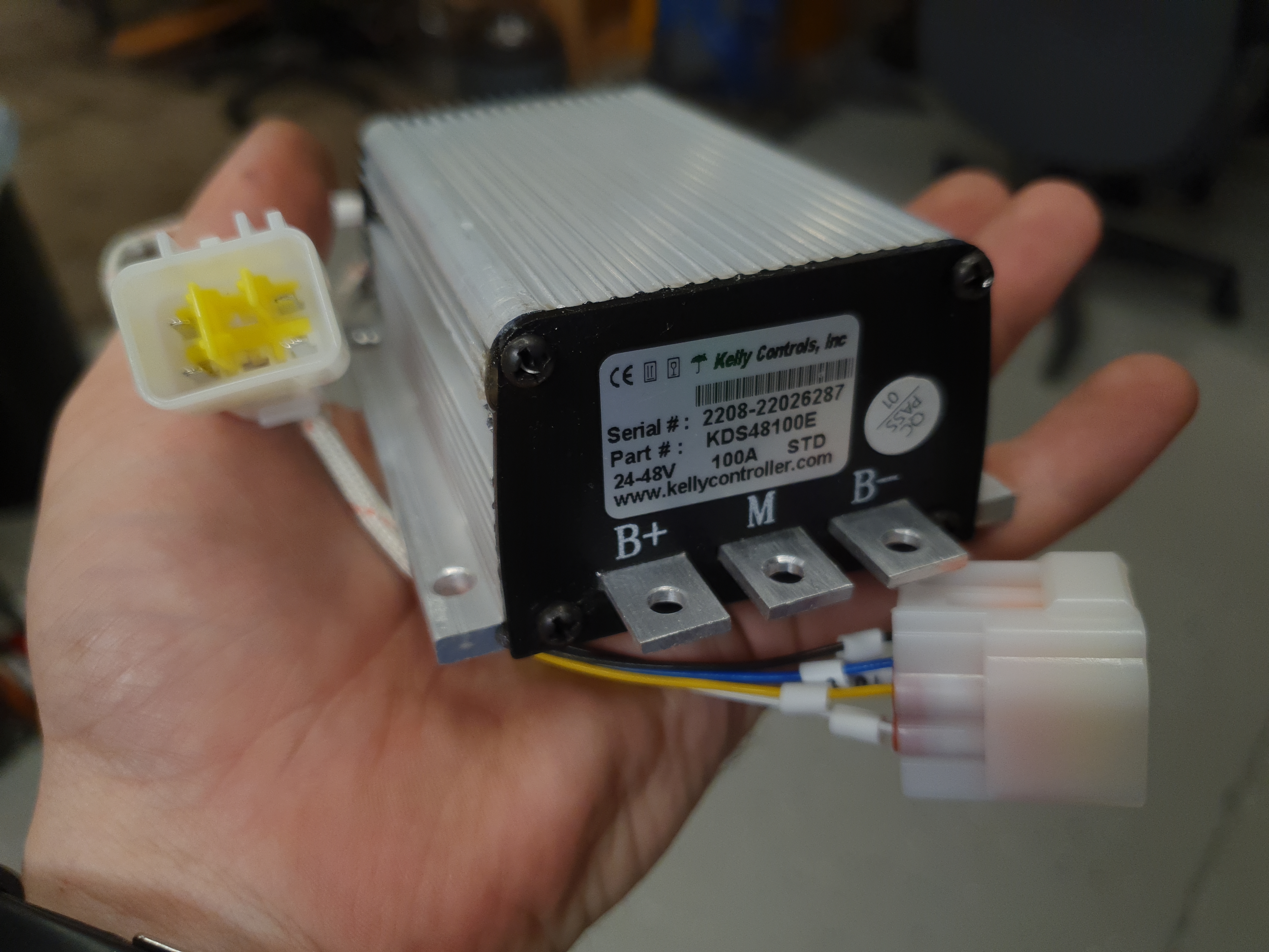
Functionally there really was not much to do with the upgraded controller, aside from cleaning up some cabling. I did have some holdups though, it's really not clear why the high current lugs are so dang close on the design of this controller. Using an appropriately sized ring terminal really does cause some curious clearances. A lot of heatshrink was used to mitigate this. 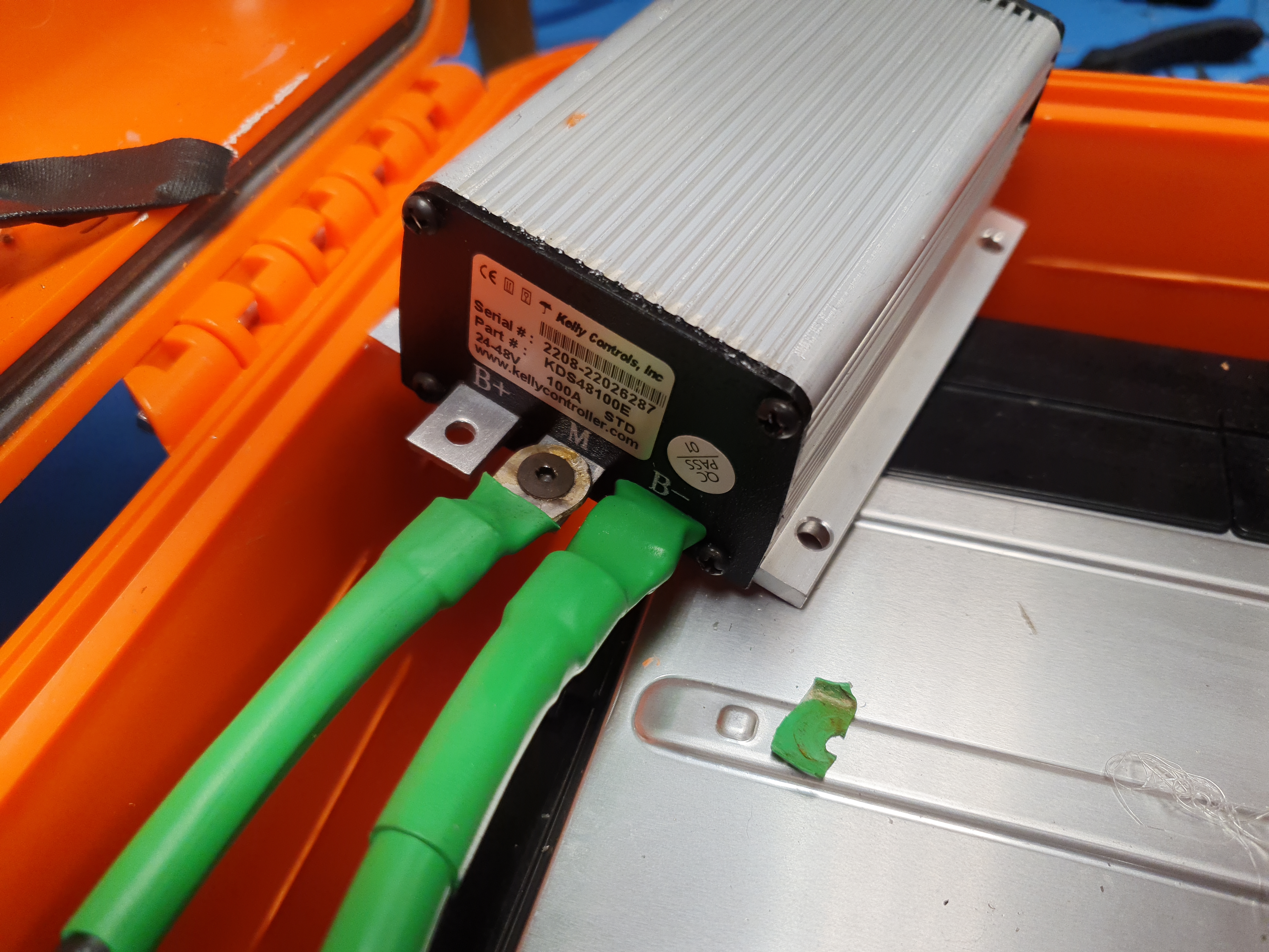
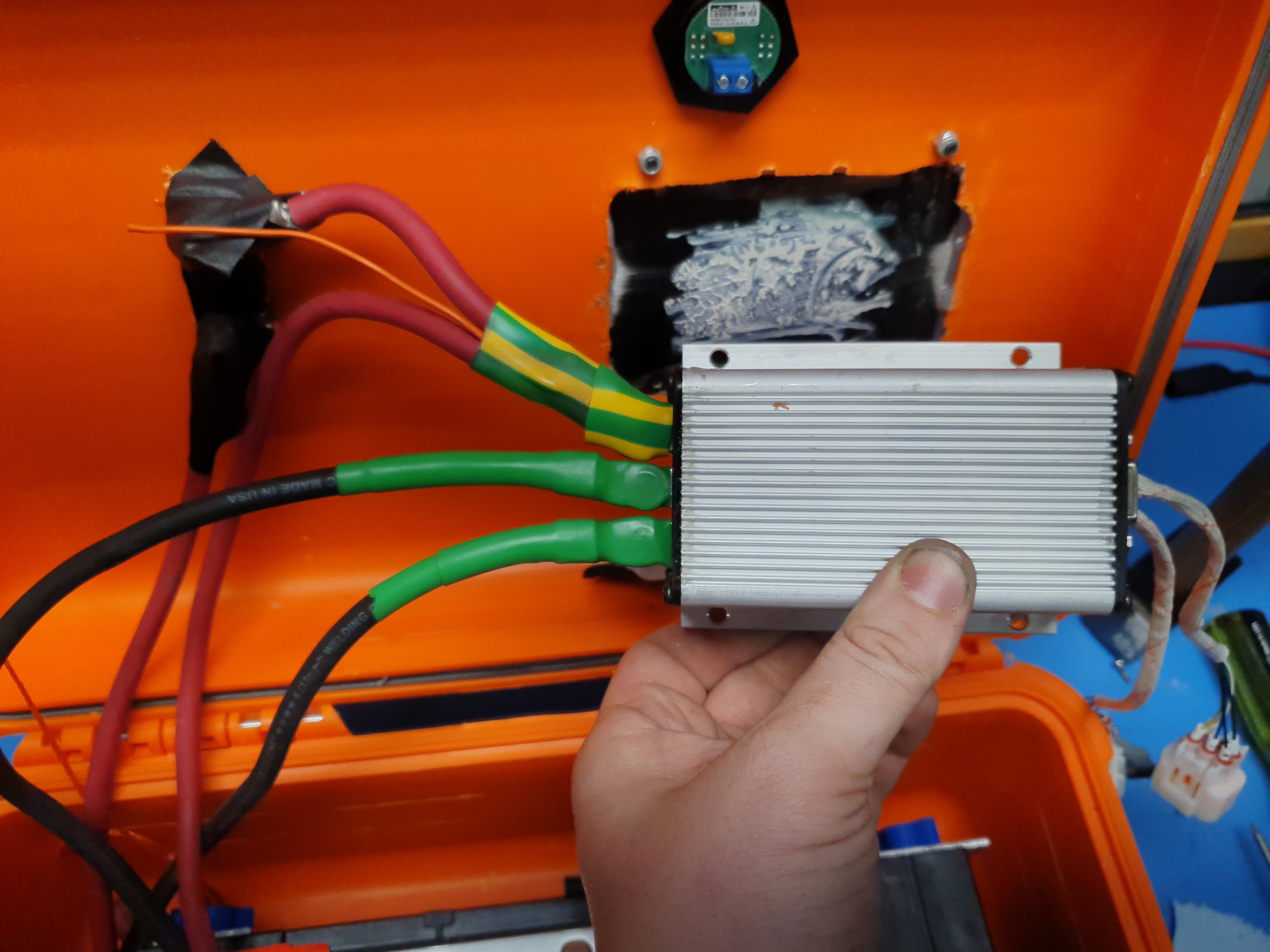
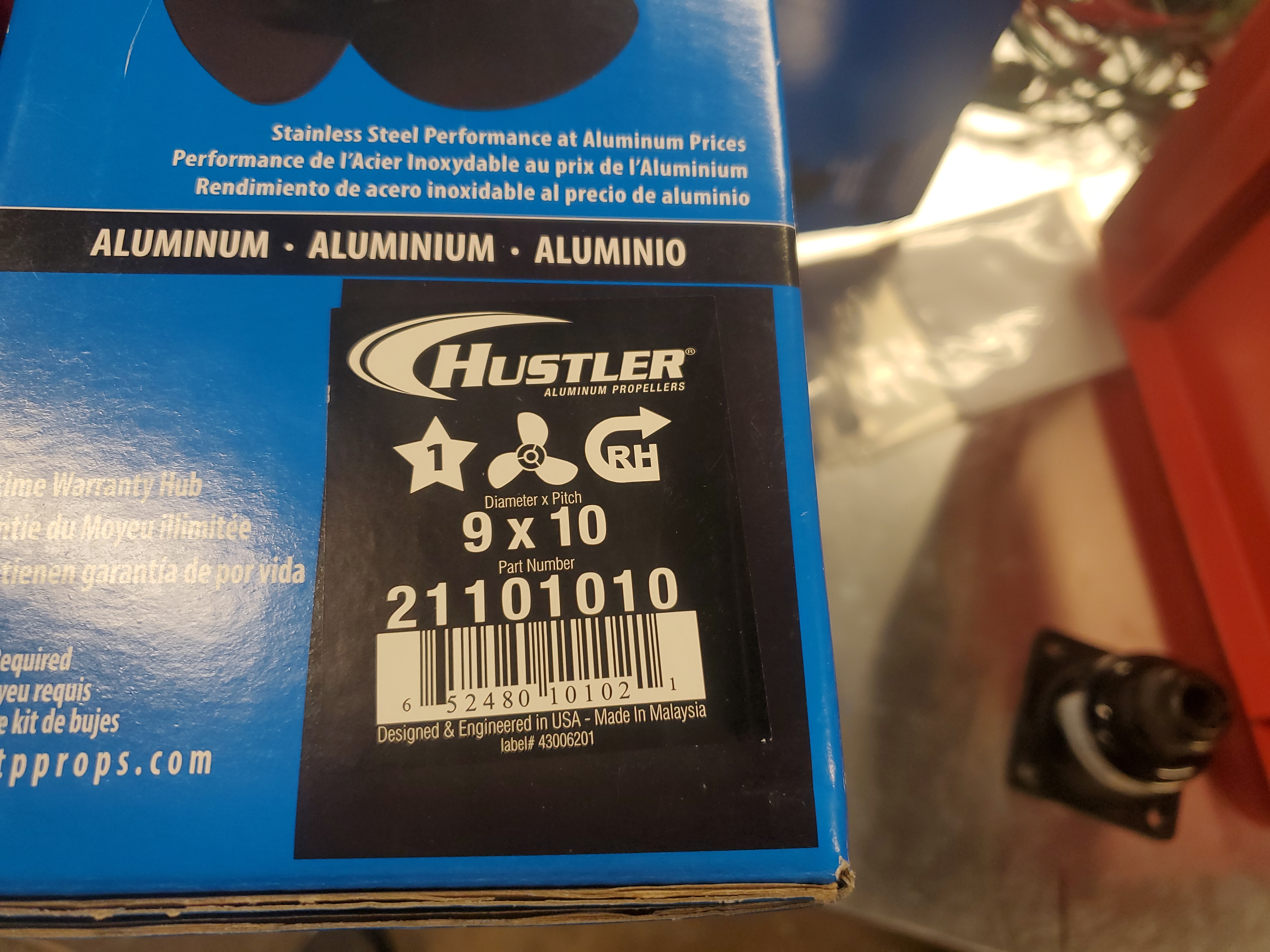
Otherwise with the updated controller, and the higher voltage battery we were all set electronics-wise for some tesing in the nearby waterways. If only there was a way to get more out of the shallow pitched, trolling motor propeller. A new propellerAt this point increasing the motor voltage on a shallow pitched propeller will only get things so far, similarly to over revving an ICE engine while in first gear it does work but it's not terribly efficient. Unfortunatley trolling motors do not have an off-the-shelf propeller available in a higher pitch. The next step was to see if the smallest engine outboard prop could work on this motor. I went to westmarine while on the way to Matt and Mary's cute day parade. They are adorable and it was a fantastic goofy time and also on the way to Westmarine :] 
This was the "call Westmarine and ask them what they have in stock today" propeller of choice, a 9" diamater 10 pitch 3 blade propeller. A "hustler" brand prop, quite fitting. 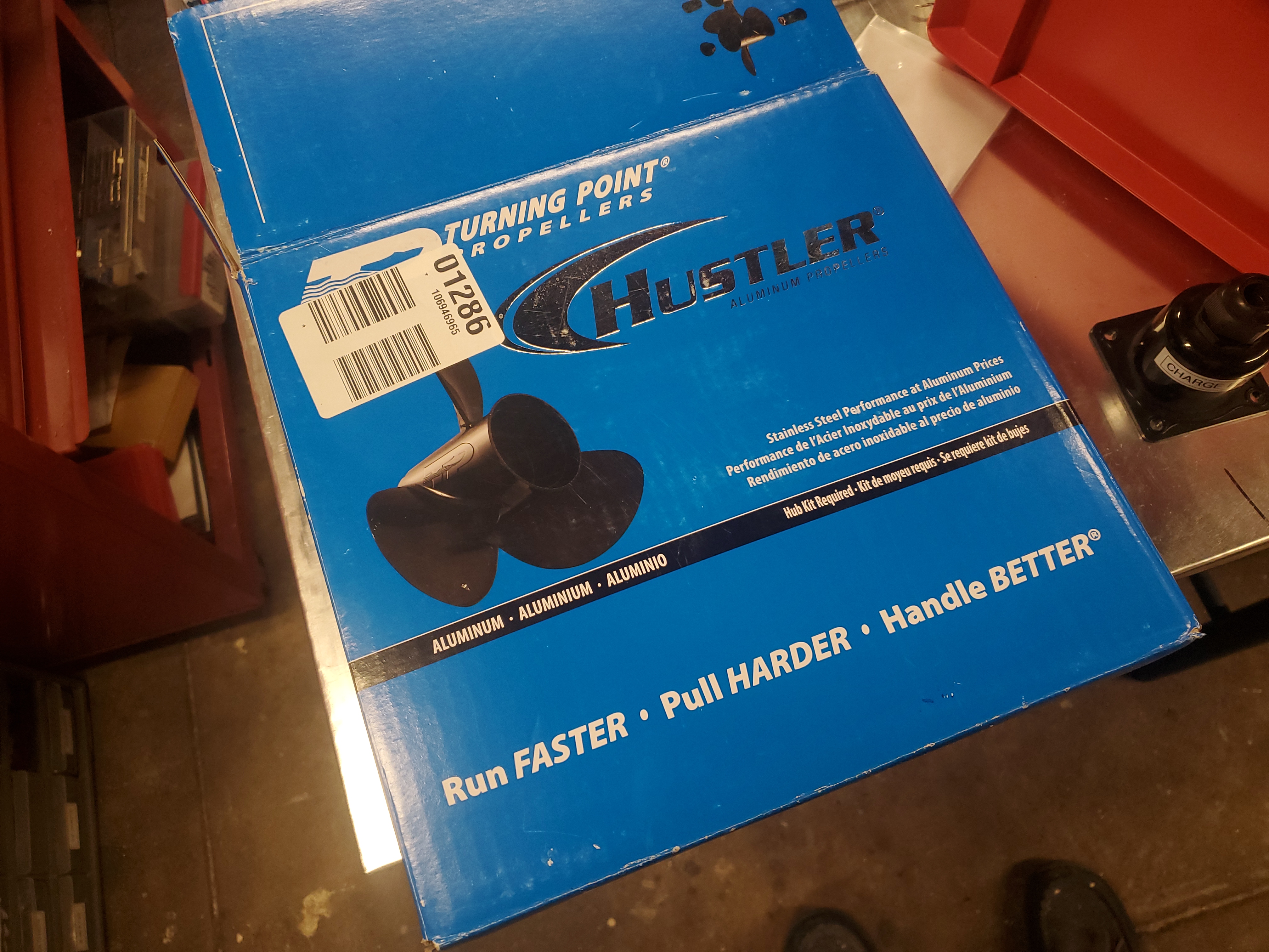
I didn't get a picture of the process of making an adapter for the prop, Ciaran made it appear from nothingness. Suffice it to say it was indeed concentric. With the higher pitched prop, higher voltage battery and higher voltage rated controller we were in business. To see if the propeller was going to cavitate I grabbed some submerged, out of frame gopro footage, shown below. First time users ended up opting to sit down and coast around, leaning to turn and zipping about the mystic river area. It was pretty great that the contraption was easy enough to operate for someone to use it un-trained. People who had experience wakeboarding or waterskiing however just jumped up and zipped around without loosing stride. Here Adam The Greek zips around and figures out the lean-to-turn in the opposite direction kinematics. Speed at full charge was significantly higher than the standard prop and lower voltage battery. We were pushing ~5-6mph while standing. The real limit was the rate I was comfortable discharging the orange battery module. I had tested at 20A, which is upwards of 1kw, any more and we would likely start cooking the pack. Given a lower DCR / higher discharge rate module we could get closer to the motor limit. What is the motor limit? Great question. From the manual we see 24V @ 53A, or closer to 1200W. Given that this is the reccomended value, we can likely operate at 20% more than that for surfboard duty cycle without much issue. This video has audio, click to un-mute Concluding Remarks
Have you noticed that there are no advertisements or ridiculous pop ups?
|


Post your comments! |
|
Comment Box loading
|