
Dane Kouttron
This write up is in progress
check back for more soon!
Project Started: 09/2024

Rockler 'SHARK' CNC RoutersRockler is a large-ish wood working brick & mortar shop, and sometime around 2010 they came out / rebranded their own tiny-shop size CNC wood router. The controller for this CNC was getting spotty and the software support was also a decade ancient. It also lacked some of the more simple things like axes-limit switches, or spindle speed control. While I am a big fan of Linux CNC, this router is small, and using a medium sized desktop seems like overkill. I'm going to evaluate off the shelf options for 3 and 4 axis control and give this machine a new lease on life. |
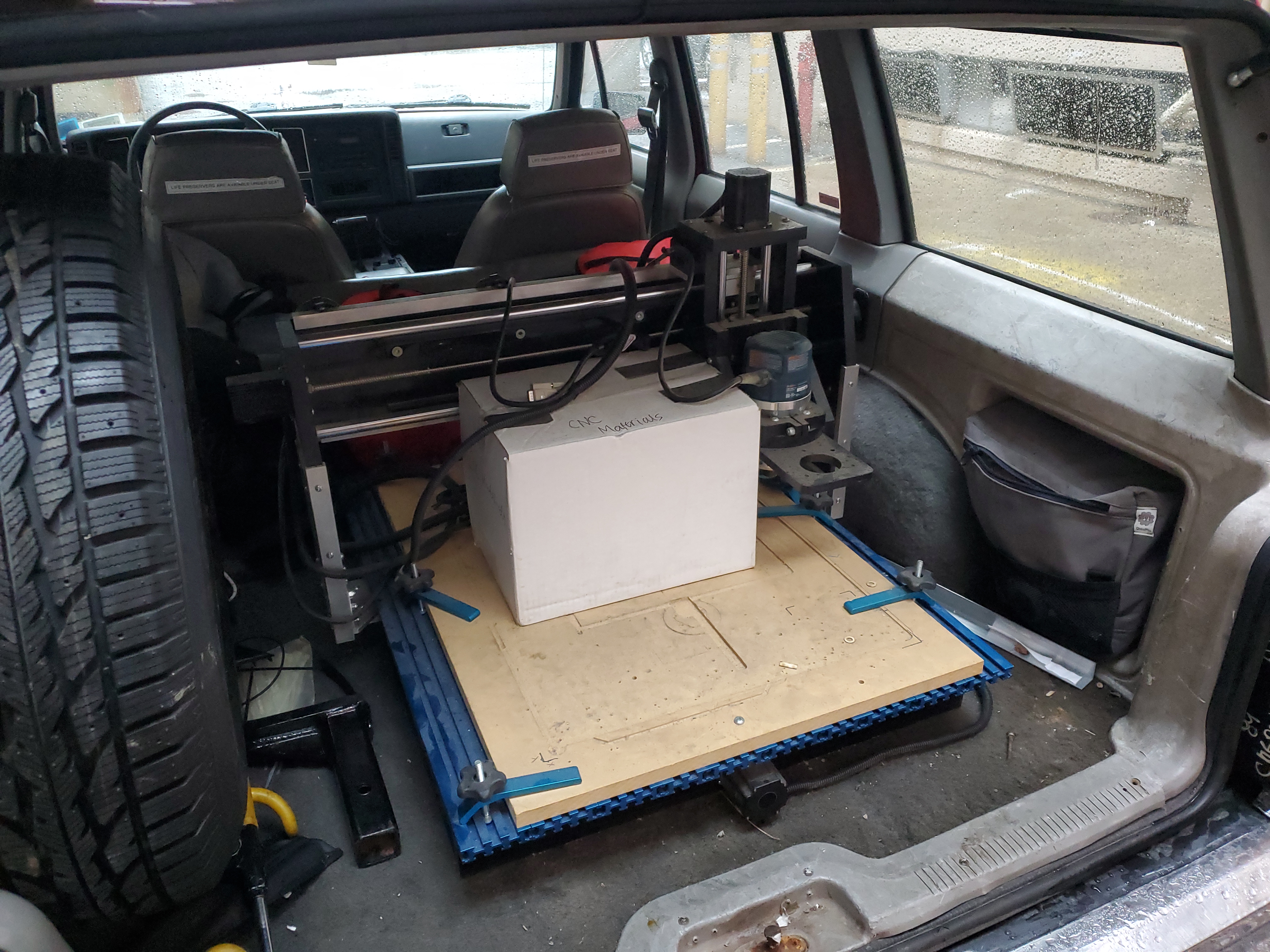
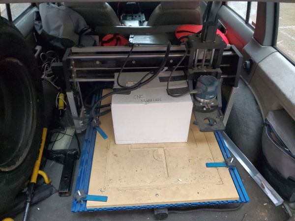
Some things end up collecting dust, there was a little cnc wood router that seemed fairly un-used hiding in a corner of a lab space. I spoke with the very excellent lab manager and asked if they were interested in de-activating it and getting the floor space back. Excitingly, they were! I picked up this cute machine on a rainy morning and brought it back over to my little workshop to see what still worked and what would need some TLC. Picking up the machine on a rainy spring day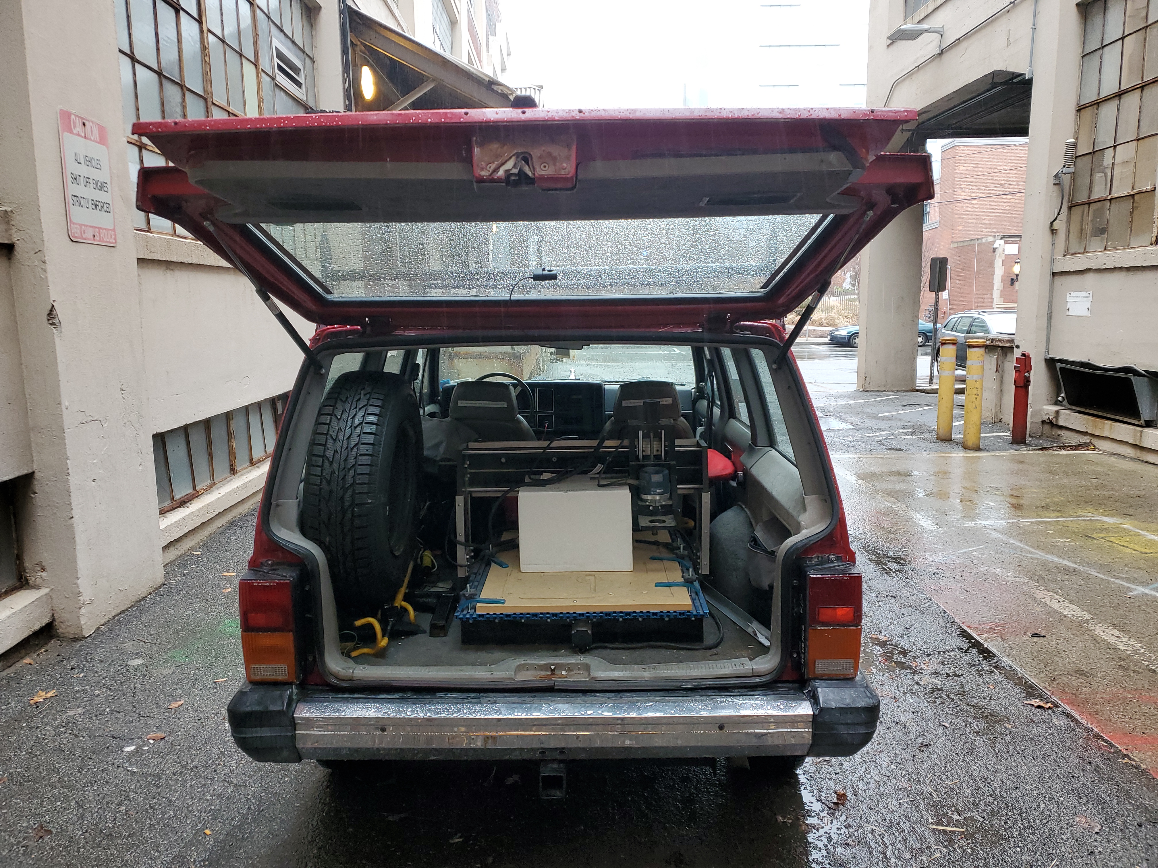
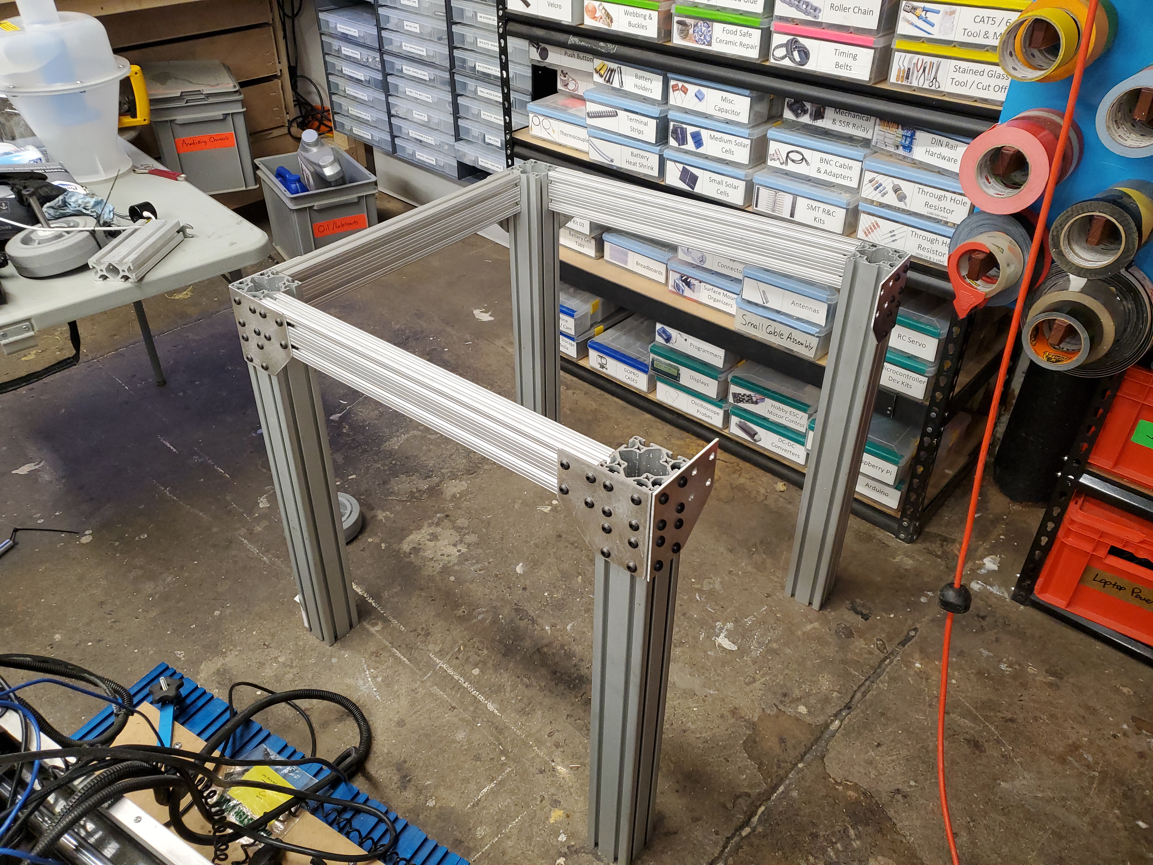
One thing that was surprising was how lightweight it was. The whole frame is a mix of delrin / acetal with aluminum reinforcements. The box of goodies included some controller remnants and a collet or two. Modeling a CNC router-cartCNC routers end up taking up a large portion of an existing desk or, even worse, hide in a corner of a room. I wanted this to be functional and moveable. Lets say you know you are going to make a proverbial dusty mess, maybe just cart the CNC outside and let the wood shavings escape your workshop. To keep on with the 'functional' part of the build, this mobile cart should also house support hardware, like the control electronics, the dust extraction and everything else necessary to run the machine. I opted to build this table out of surplus 80-20 from a lab clean out, but ~4x4 wood could work similarly. In the spirit of recycling, I designed the assembly to use 3"x3" extrusion while the horizontals were "1X3" spars. 80-20 extrusion is remarkably useful for CAD++ or, design a sub-structure with the intention for it to support auxiliary additions as the design comes into fruition. Shown above is a simple solidworks model of the assembly, with some notes including vacuum, dust collection mating hardware, and some other rough positioning. Making a cart for the routerWood routers generate a lot of wood swarf, tying a vacuum system directly to the lil CNC seems like a great way of keeping things from getting out of hand. Having the router on a cart also means it's not fixed to a table taking up space and can be carted off based upon need. Making some bracketsWaterjetting and plasma cutting are a great way to crank out 2D brackets, but if you don't immediately have access to either, you can manually make brackets fairly easily with hand tools. Paper and double sided tape really work wonders for making fairly consistent parts. I used 3M thin doublesides tape [link] and used a solidworks drawing as the template. Normally when making a drawing file, I remove the crosshairs from holes, but this time they are really helpful to align a nailpunch. Before taping down, use IPA or a solvent to clean off any grease or film from the sheet metal surface. For these parts I'm using 1/8" thick 6061 aluminum sheet stock. Make sure the solidworks drawing scaling is 1:1 and your printer is also set to 100% scaling. Following the linesWith the paper tacked down enough to not rip into pieces, the real trick is taking your time with the bandsaw. This is a blade that's more appropriate for straight cuts, so I did not really attempt any of the radius's. It's important to try and have adequate lighting on the cutting side to help you stay alligned. Drilling HolesRealistically, I should have used a smaller starting bit for this, but the large bit seemed to float quite well and allign for the punched allignment points. The paper does get quite ripped up around these holes, and for steel, you really should be using some lubricant so it will get further destroyed. The thin 3M tape realy does a great job holding the paper on for this short run. To cleanup the edge finish, a chamfering bit is used. While I would normally use this for countersinking, it does a great job of cleaning up drilling remnants. SandingFinally the last bit was to cleanup the edges on a 3" wide belt sander. This makes quick work of the radius's that we couldnt quite get to with the bandsaw. Assembling the baseWith the brackets hand cut and drilled, all that was necessary was to add in some 80-20 fasteners, in this case 3/8-16 T-nuts. To make four of these fit on a 12" x 12" sheet, i did opt to puy the mating screws a bit close, and as a result half-length t-nuts were used for the inner bolt mates. I was really fortunate to get these 3X3 80-20 extrusions from a lab cleanout as this came out great. Initially I was concerned that these brackets would allow too much toe-out, but given that ancillary brackets get added during the rest of the build, we can tackle any toe-out issues towards the end of the build. Assembling the base: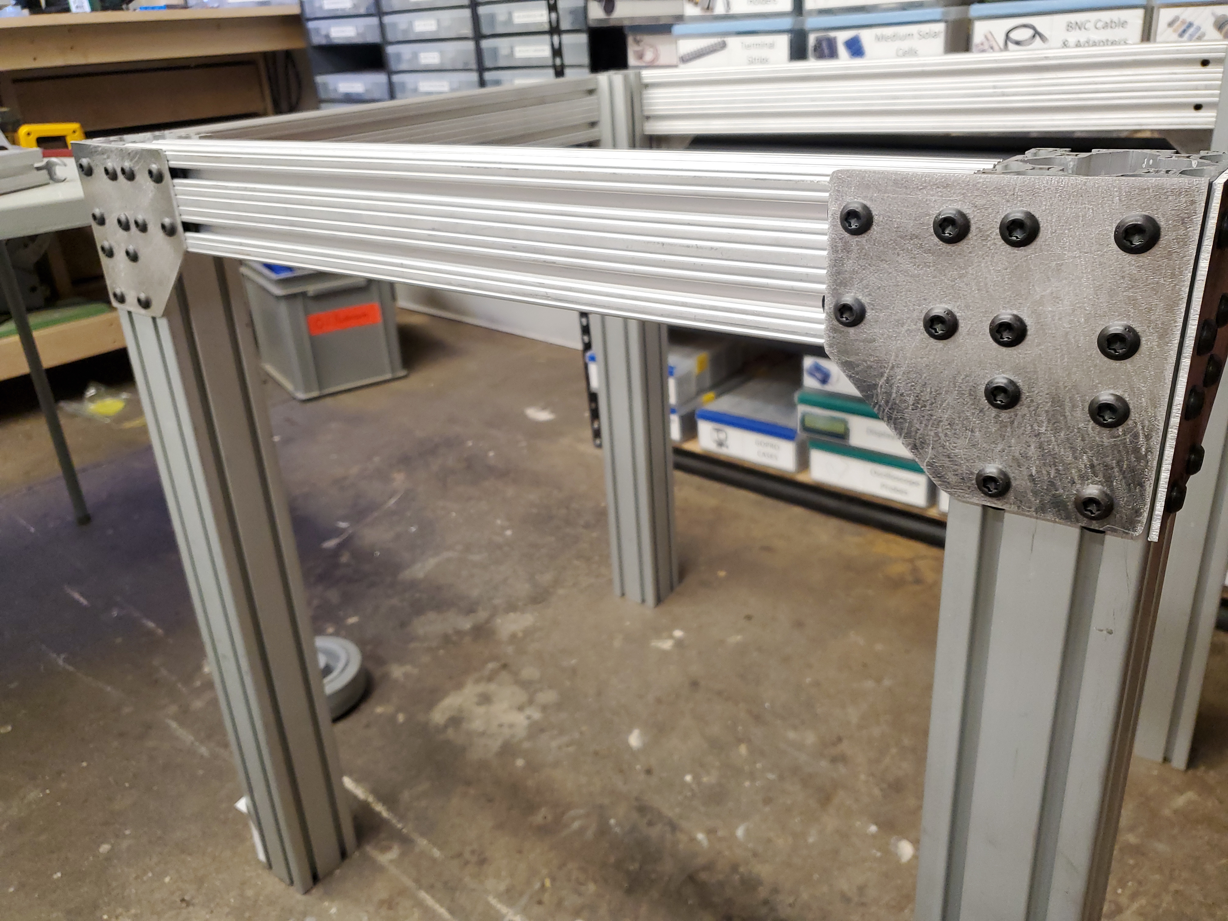
Rockler in Cambridge Ma closed up shop due to building rent increases, which became comically inconvient. This 259.99 USD vacuum was purchased for $50. It does feature an auto-on tool switch built in, however it did not appear to work reliably. The vacuum itself works remarkably well. I'm a pretty big fan of cyclone seperators to keep the heavy chips seperate from the dust, as it also results in significantly less vacuum-bag changing. First step was to sort out how to mount the vacuum to the underside of the table such that it becomes an integral part of the whole assembly. There's not a lot of mount points built into this, however after removing the handle, we get two #10-sized self tapping screws. This, along with using the planar surface underneath the handle should work as a reasonable mounting strategy. 

To mount the 3 x 1 80-20 spar, I folded some 1/8" 60-61 aluminum scrap and traced the rough position of the associates screw holes. Given that the self-tapping plastite screws would loose grip after been cycled too many times, I opted to check dimensions a few times before finalizing the mate. There is a pushbutton on-off for the vacuum and fortunatley it latches in-place and persists during a power cycle. Finally the 80-20 3X1" spar gets mated to the rest of the frame. 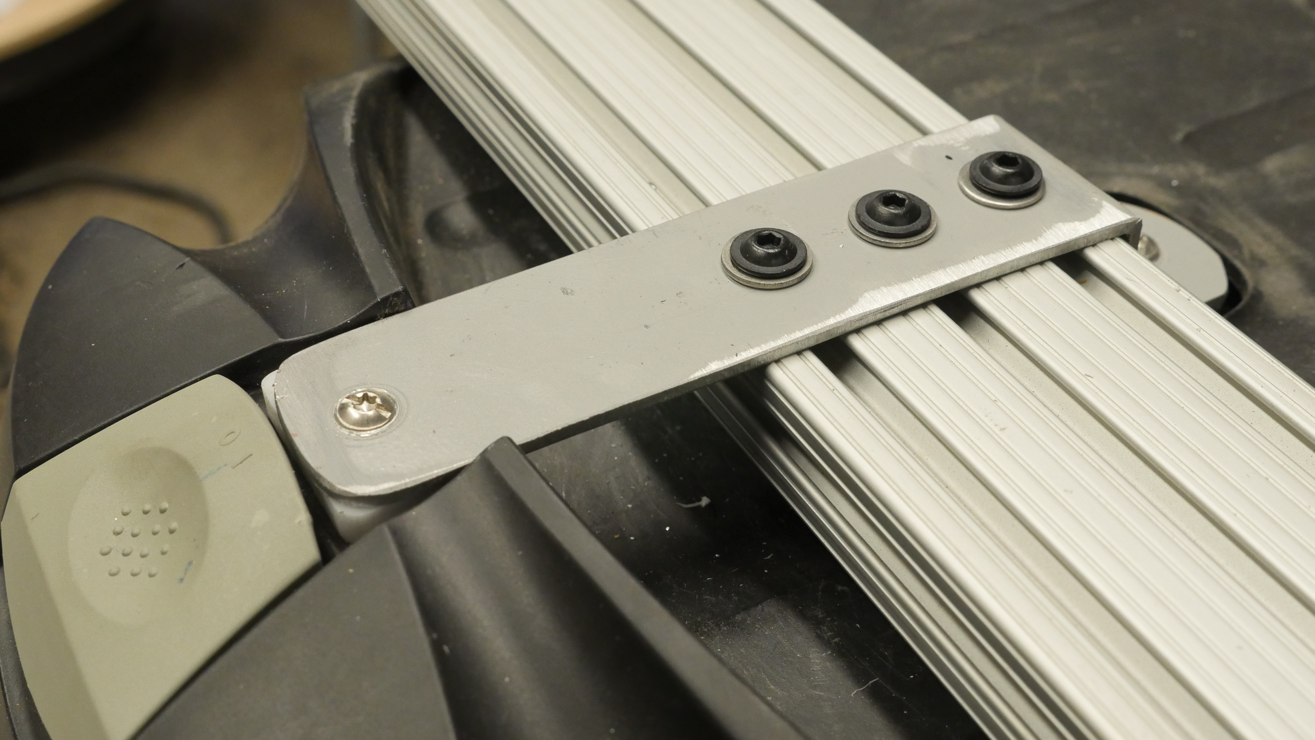

Simple feet for the 80-20 cartThe plot with the 4-legged cart was to have the rear portion be wheeled, while the front just has shoes that compensate for the height offset from the wheels. I opted for an adjustable 3d print design, however I know the limitations of prints. I knew the bottom surface would eventually abrade-away, so I opted for some HDPE sheet, similar to plastic cutting board material, to take the brunt of that abuse. The advantage of using 80-20 hardware was that once I leveled the cart i could lock the foot in a fixed position. Getting all eight machine screws to line up with the channels was quite a bit of effort, but once complete it really worked well. Copies of the print files and cad files are included below under the [CAD] section. Taking a look at the stock stepper controllerI was somewhat curious if the stock controller would work out, given that it was a decade old and only supported by some windows-xp era software, I was a bit hesitant to design around it. Taking a look at the insides we get a a quick overview. We have an un-branded 24V 5A supply to run the steppers, a solid state relay to control a spindle and four stepper motor controllers tied to a microcontroller. Spindle control is binary, its either enabled or disabled. This is admittedly fairly compact. I'm not totally certain that the power supply is actually sized correctly for these larger steppers, but there's likely an assumption on multi-axes motions. The stepper drives themselves live on a daughter card, which is removeable / replaceable. This is pretty great if replacements exist, but given the machine's age, its less likely. 

Lets look at the stepper controller board We get four seperate boards, with v-routes connecting them together. They look somewhat out of place in relation to the rest of the machine, as if they were OEM modules. As it turns out, they were! These are G250X Gecko 'digital step drives' [Link] . These are 3.5A (max) stepper drivers, intended for 15-50v bus voltage. So as it turns out, these stepper modules are replaceable, as gecko still manufacturers these (2025). We also spot three of the four modules populated, so this control motherboard was probably intended to support a rotary axis for rotary engraving. The phillips mounting screws for these are dubiously placed but otherwise this is actually a very serviceable module. 
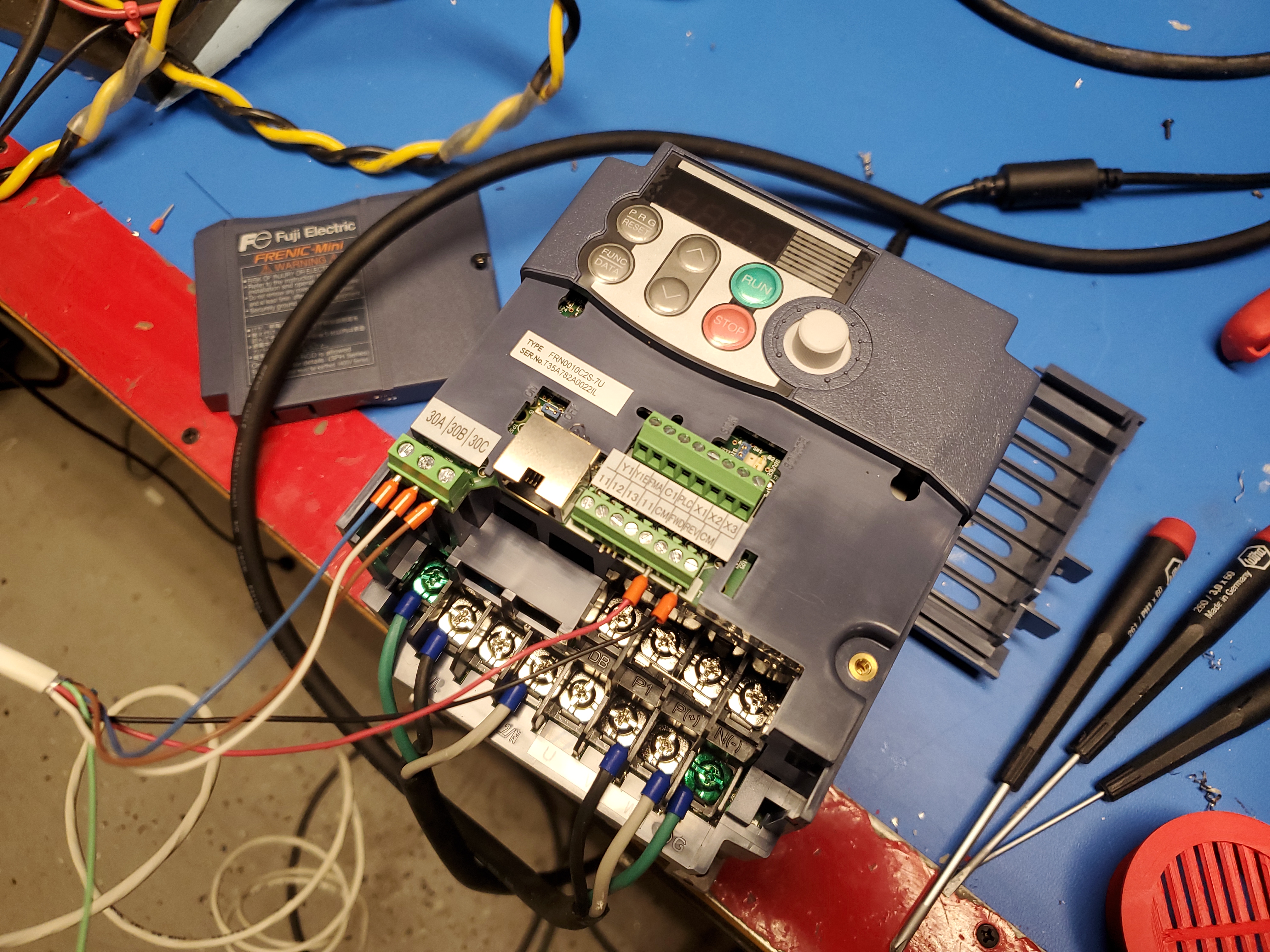
Does the stock controller work?After around 6 hrs of driver fiddling and old-laptop issue hunting, I was able to get the stock controller up and running. This was an unfortunatley incredibly fiddly setup, involving having a laptop plugged in constantly, and some really goofy bugs. I was really happy mechaincally everything appeared functional, even the router spoolup was great news. With the SSR, you are somewhat stuck at fixed speed, aside from manually adjusting on the router itself. This is not the end of the world but it would be nice to have control over the whole machine. Clip below has some audio, but auto-plays muted. The controller works, which is great. The stepper steps, the spindle spins, but unfortunatley this controller is only really supported by an ancient software stack, which is a bit buggy. The option is to ebay the stock controller and build one from scratch or live with the buggy xp-era software stack. There are some parts i'd really like to improve, like having axis limit switches, adding a pendant and running everything from a standalone controller. So yeah we're building a new electronics setup for this monster, hopefully with better performance and spindle velocity control. Sorting A Spindle ControllerTo get spindle speed control on the bosch router there's two options: easy or expensive. For reasons that have yet to be explained, I opted for installing a VFD to allow for variable spindle speed. The bosch router that came ith this wood CNC has a small potentiometer on the side where you can set the RPM from 0-7. This requires manually setting the router speed on the router itself before running the job. It appears that this is an SCR chopper style driver, where it just applies a varied duty cycle with a zero-cross SCR. Adding a VFD does have some advantages, it supports a standard 0-10v signal for frequency control, supports hard-stopping the spindle (with a breaking resistor), and supports ramp-rate control. We also get an analog output proportional to spinlde load, which is a very useful indicator to tell you if you're overloading the machine. "But Dane where are all the 110v VFD's"There are a lot of 220V single phase to 208 3 phase ac VFD's, but very few industrial options for 110v out. One of the less documented features of a VFD with 208 3 phase out is using the phase-to-neutral connections will provide a single phase output. Some VFD's contain a neutral output, so in this case we hunt down one that will suit our needs. Adding some vents for the VFD enclosure 2KW vfd in an enclosure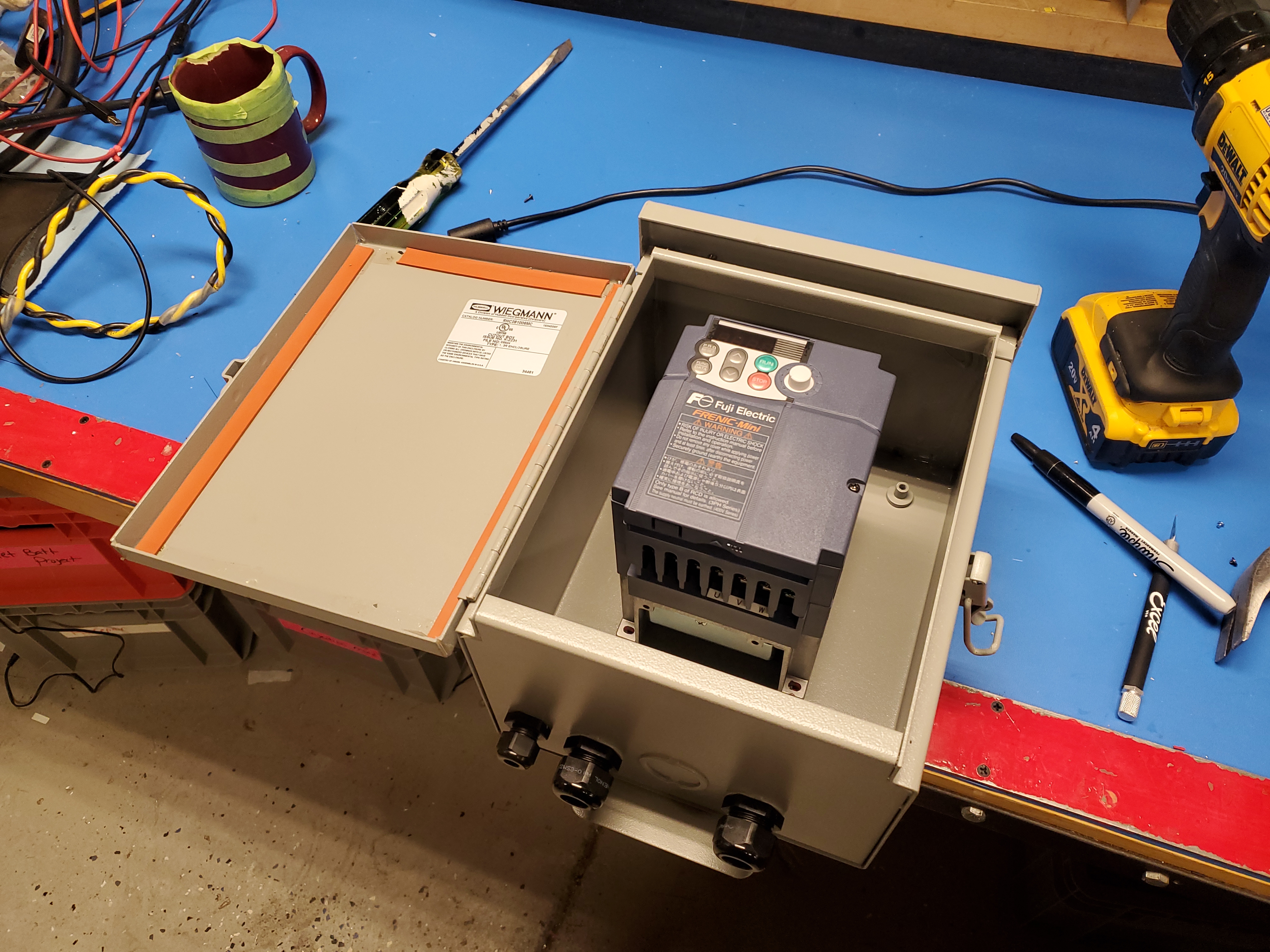
mounts Rotary couplings on vacuum fitting. Cyclone seperator for CNC dustTo avoid the vacuum back from filling up quickly I'm opting to try and seperate the waste stream, let the vacuum bag take up the micro dust particles, but pull out the large bulky items into an easy to empty jar. I've opted for this approach on a few projects, ranging from a metal CNC to my wood working tools. Cyclone seperators are however, large and do require plumbing to support the flow rate necessary to make them work. The plan is to use the existing screw holes in the off the shelf seperator and attach some kind of adapter to allow a mason jar to thread into it as the removeable offcuttings accumulator. you may ask yourself why i'm not using a plastic jar . As it turns out, the two plastic options I did look at, tended to deform under vacuum and somewhat crumple. This was not too terrible, but the cyclical crumpling would likely cause the plastic case to fatigue and then leak vacuum. 
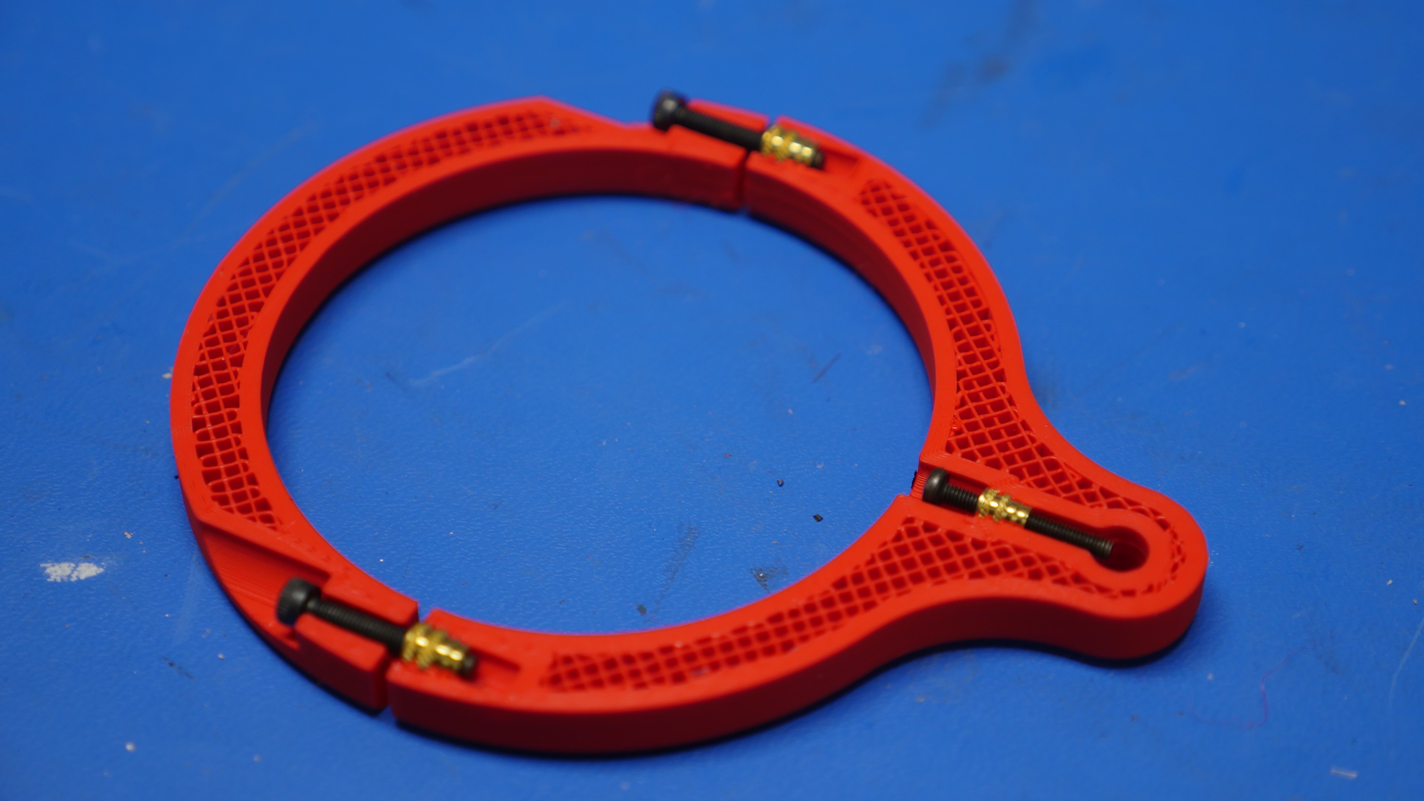
To make this tall contraption, a 3d printed ring with thermal inserts picks up the four base holes and allows four M4 screws to connect the jar lid holder to the seperator. The procedure for making this was fairly straightforward. I started with printing the adapter [files are listed in the downloads section], coating the outside of the white plastic lid with silicone RTV, and subsequently hammering the lid into the print. We now have the lid part installed but the lid itself is blocking the flow of vacuum. 
We need to cut as large of a hole as possible around the inside of the print into the lid. I initially tried a hot-knife, or literally a sharp knife attached to a modified soldering iron. This was unfortunatley messy and innacuurate. I normal utility knife did a fairly reasonable job. 
With the threaded lid portion pressed into place, sealed up with RTV, the print set up with thermal inserts it was time to fully assemble everything. Here's a bottom-up photo of the assembly. 
This whole setup is fairly tall, for reference here is the seperator and jar standing off the floor, there's not a huge amount of vertical space to play with. We know that the jar needs room to un-thread and slide out, so it should ideally be at least and inch and a half from the floor, if not higher. 
Vacuum feed spineTo help make the vacuum tube self-supported, I opted to add a fiberglass rod. This provides a springy restoring force to pull the gray plastic tube into shape. I initialy thought of options to put this internal to the gray tubing, however that proved tricky. If it was internal to the tubing it creates a surface where dust and chips can collect on. It's also difficult to mechanically attach to the inside of the tube. Shown below is a cross-section of what I came up with. 3D printed spine parts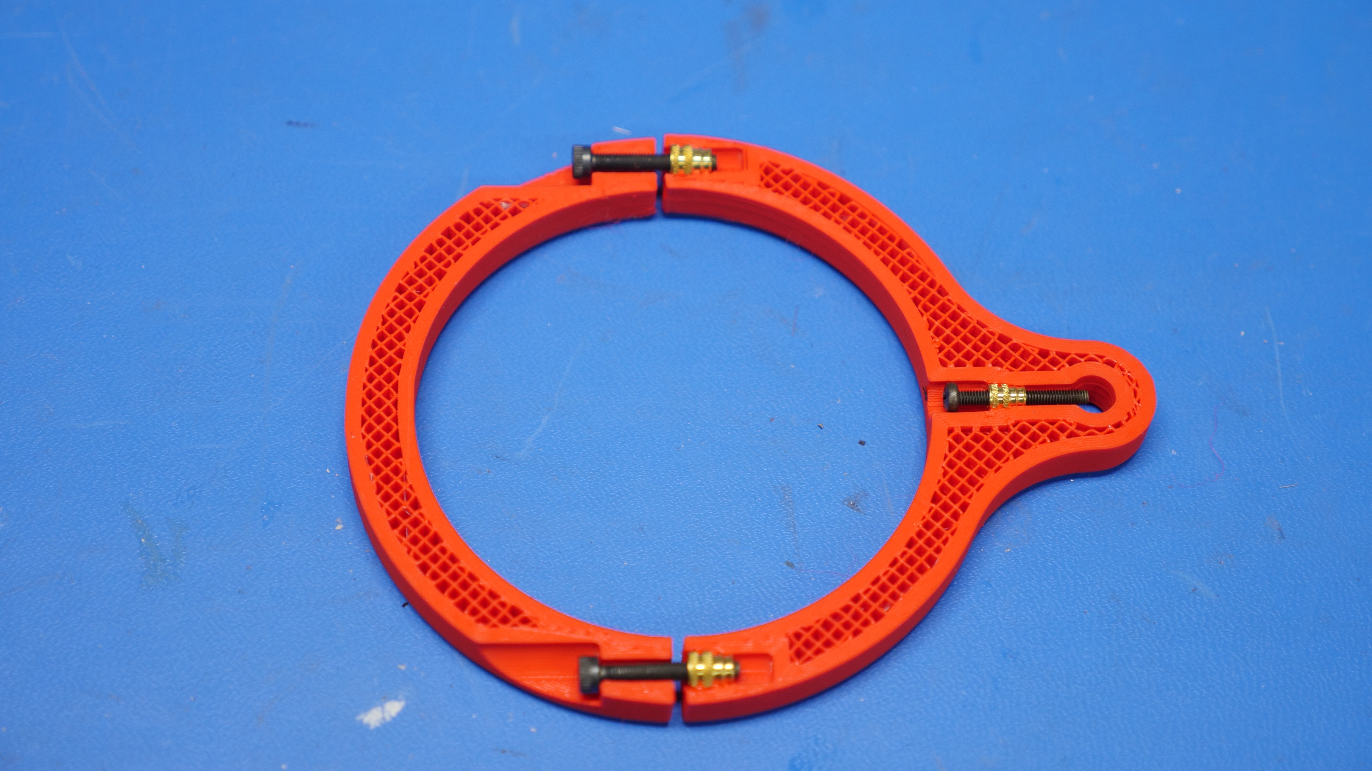
I came up with a pretty simple design. I needed two things, something to attach to the tubing rigidily, and something to lock the support to the fiberglass tube at a fixed position. Thermal inserts are used to provide the mechnical mates. A smaller M2.5 thermal insert is used to allow a 20mm M2.5 screw to press up against the fiberglass rod 'spine', while two M3 thermal inserts are used to attach the two half rings together. I found that opting for a high external wall count really increases part strength, so these used 6 walls and 50% infill. 3D printed spine assembly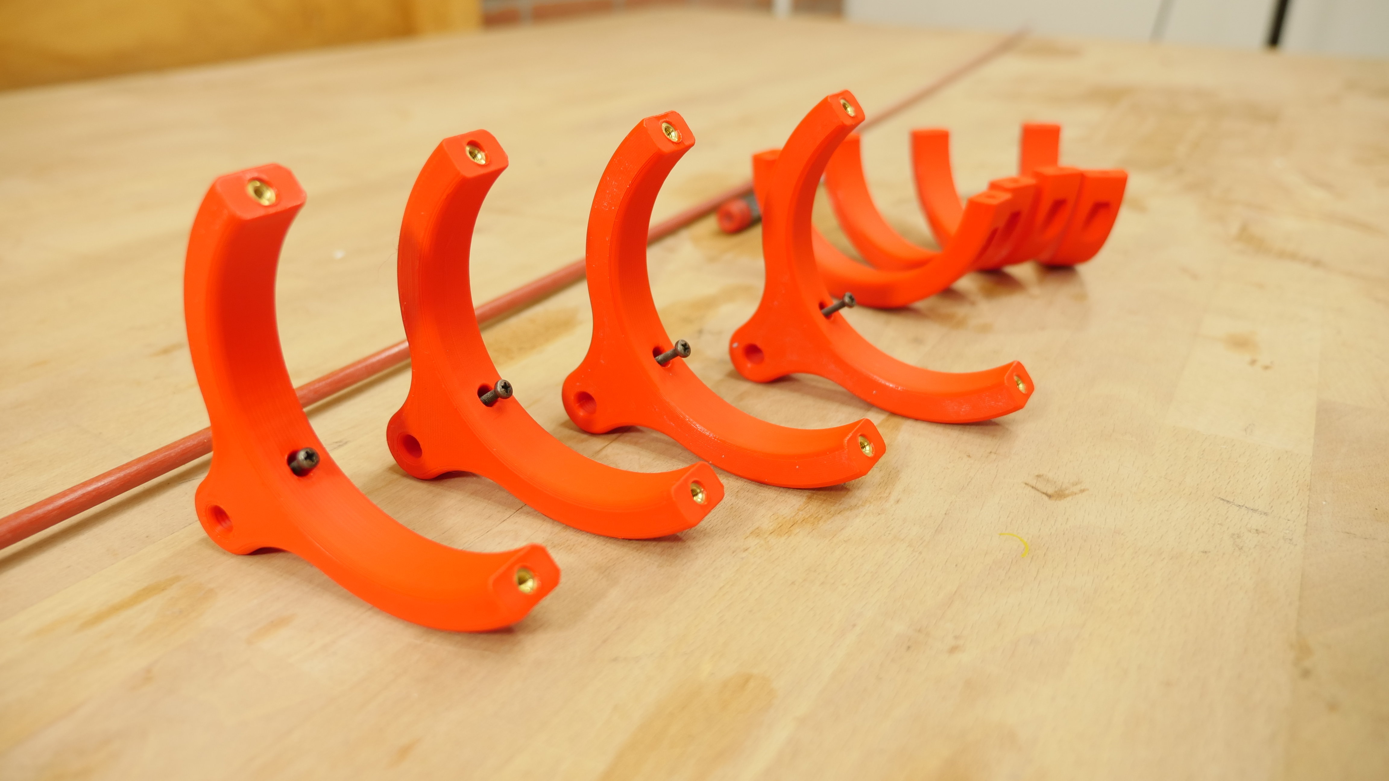
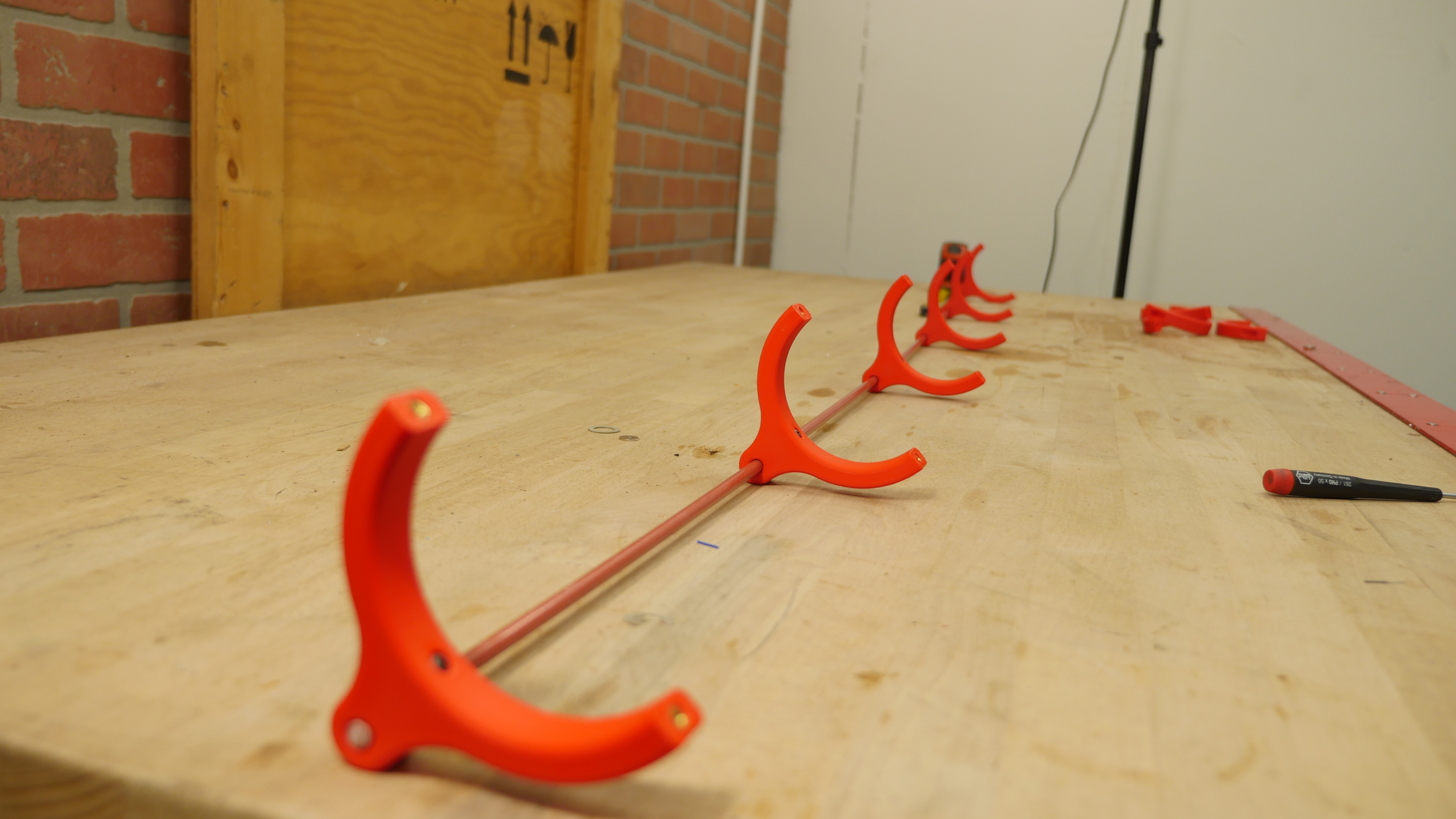
Initially I had plotted to install the spine with the semi-flexible gray tubing removed from the machine, but installing the spine with it already on the machine was fairly painless. I had allocated a lot of space for the screws to protude into the main printed part and as a result could get away with enough screw length that the parts fit over without much issue. This would have been a good application for an electronic screwdriver with an allen-bit but alas I went at this manually. Shown below is what that assembly looked like. The base of the router-holder assembly is 13 x 6 inches, and i'd like to use this outline as a mating surface for a dust collection shoe. Preferably the shoe is removeable without specalized tools. I had some fairly long nd magnets from a shop clear-out, and with some creative 3d printing I came up with a simple two-part print that captures and adds these magnets to the router head, shown below. While I initially mounted the open face of the magnets facing down, I could have opted to capture the magnets by using either a very thin bottom layer line, or capturing the magnets inside a 3d print. This can be a somewhat dangerous game as the magnets themselves will significantly interfere with the printer's nozzle assembly. Ideally the dust shroud is removeable, such that you can observe your work, but also can snap in place to concentrate the vaucum in the desired work area. Given that the Rockler CNC has a fixed shape cut out of delrin, something that wraps around this is needed. It's fairly large at nearly 12" in length, which, could fit on a large format printer. To make this a bitmore print-able for normal sized 3d printers, I opted for a split design. The plan is to use two aluminum 1/4" rods hold the parts together with cyanoacrylite glue. As these parts are somewhat in the war-zone I opted to print with a fairly thick wall thickness and high percentage infill. Initially I was hoping to be able to adjust the shroud height, however that introduced a number of mechanical design constraints that really were not necessary. I determined that making two versions [tall and short] should suffice for most cutting operations. With the dust shroud printed parts complete, lets assemble everything. After some time to let the glue set-up, it's time to add the thermal inserts to the build. These are [mcmaster carr link] M3 thermal inserts. The goal is to provide some positive retention for the brush cover. My go-to method for installing thermal inserts is to just heat the insert on a screw and install. This is significantly better than just using a hot soldering iron to install the insert as with the screw method, the threads are occupied with the screw, so no plastic can sneak in and get in the way. There's six thermal inserts per side of the dust shroud, two shrouds per assembly and two assemblies, so time to heat up some inserts. Finally time to install the brush and lock it in place. With the shroud printed, the glue set, the brush installed it's time to test fit. It latches in place remarkably well with an audible click. I'm so happy with how this came out. It came out great The dust shrouds did seem to be missing something, and with the large brushes installed it was pretty clear there was a solid lack of googley eyes. I did not plan for this, so some add-on prints were needed to convert the outside surface to a flat surface that would work for adhering the eyes to. 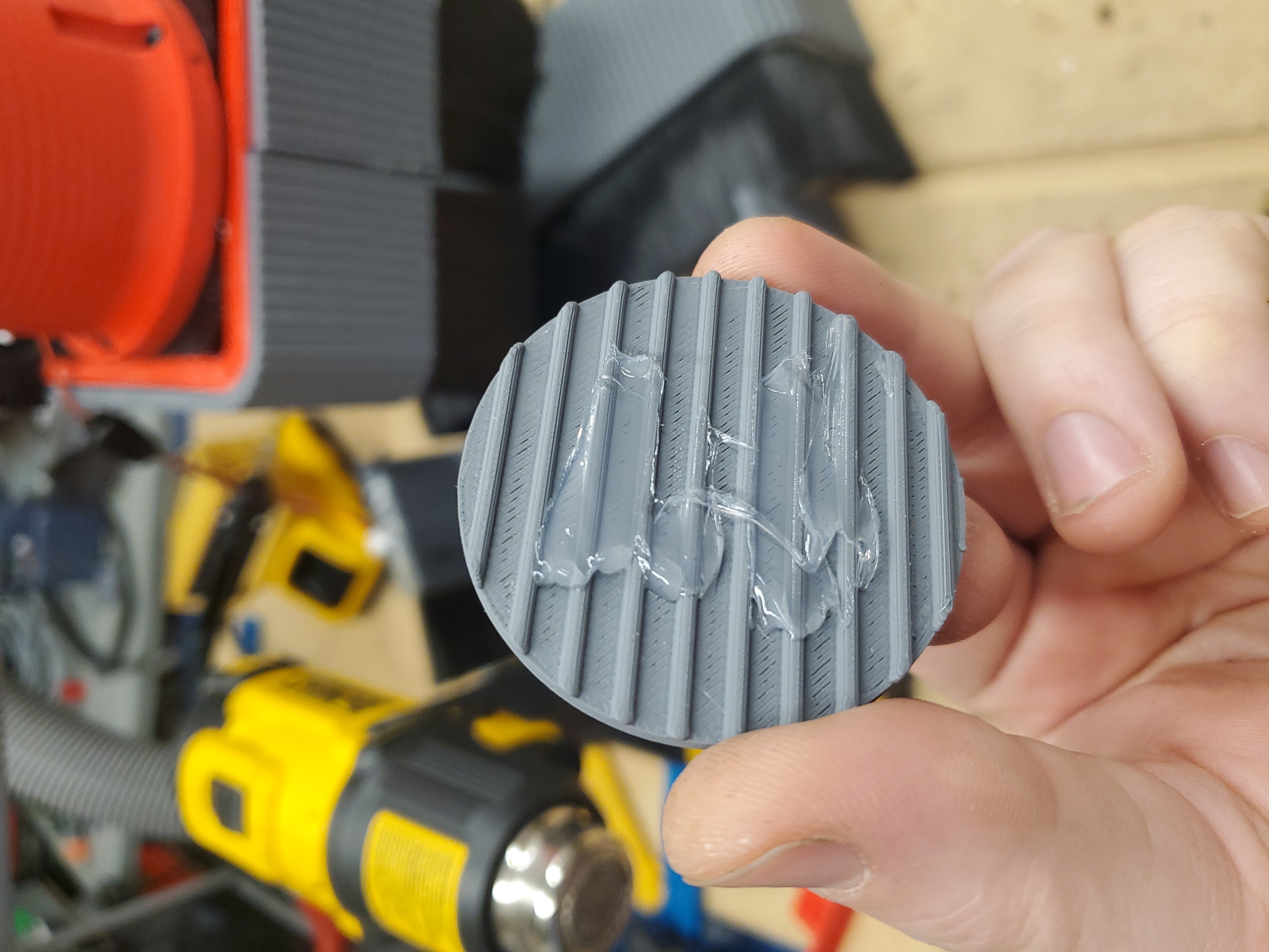
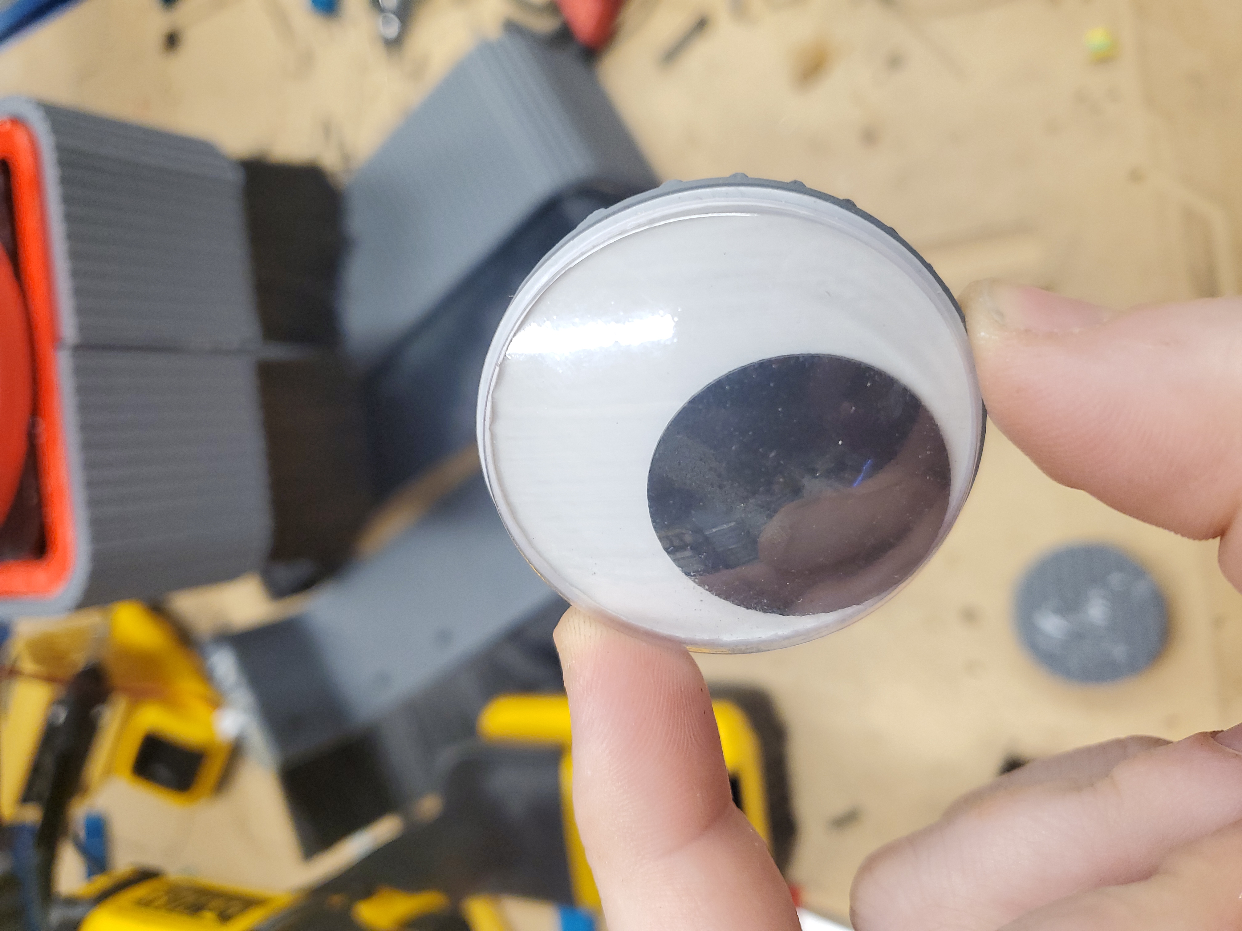
I used RTV to attach the prints and googley eyes onto the outside of the two dust shrouds, and it came out great. It has a goofy character to it, and the brushes have mustache vibes. 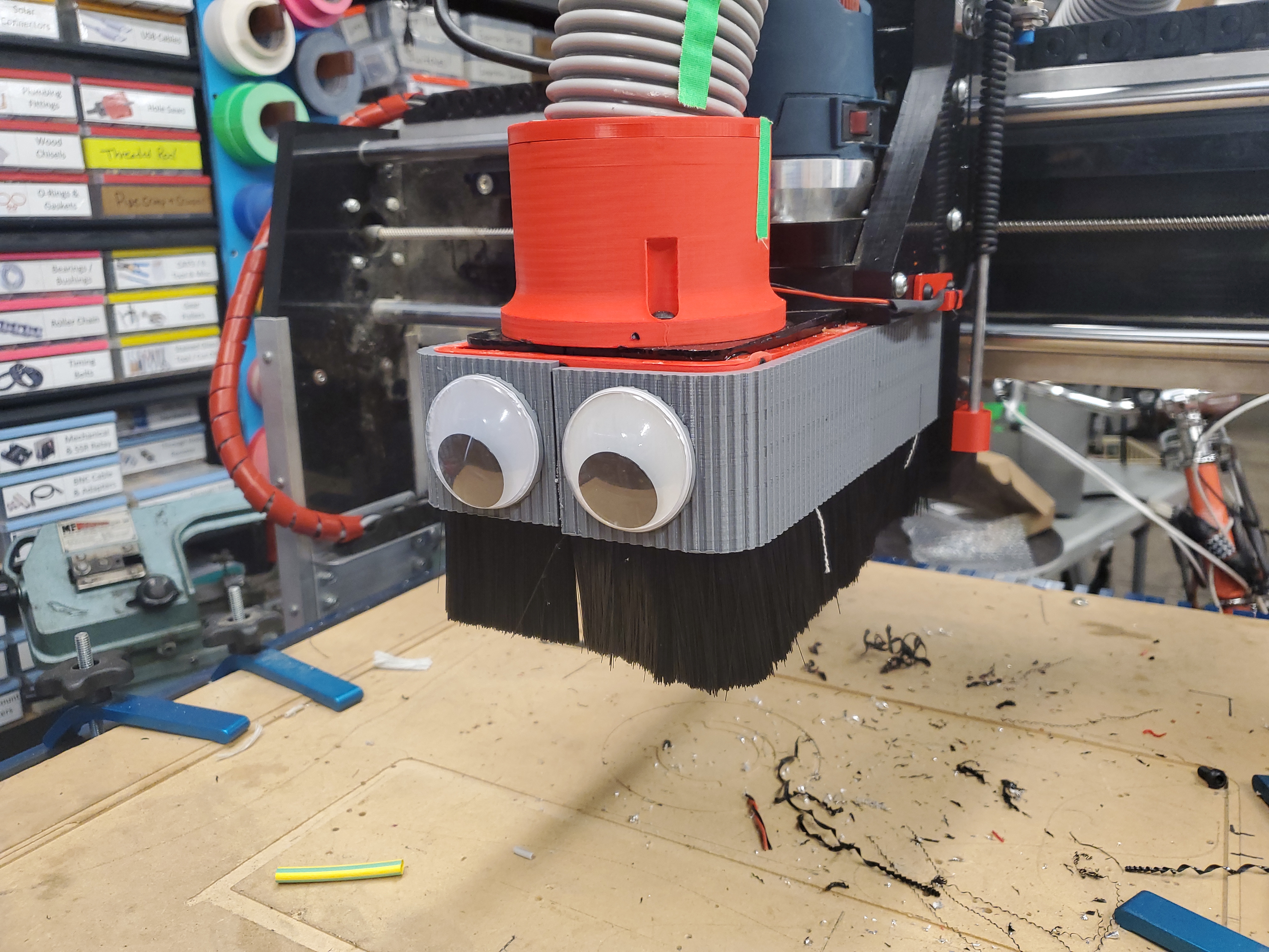
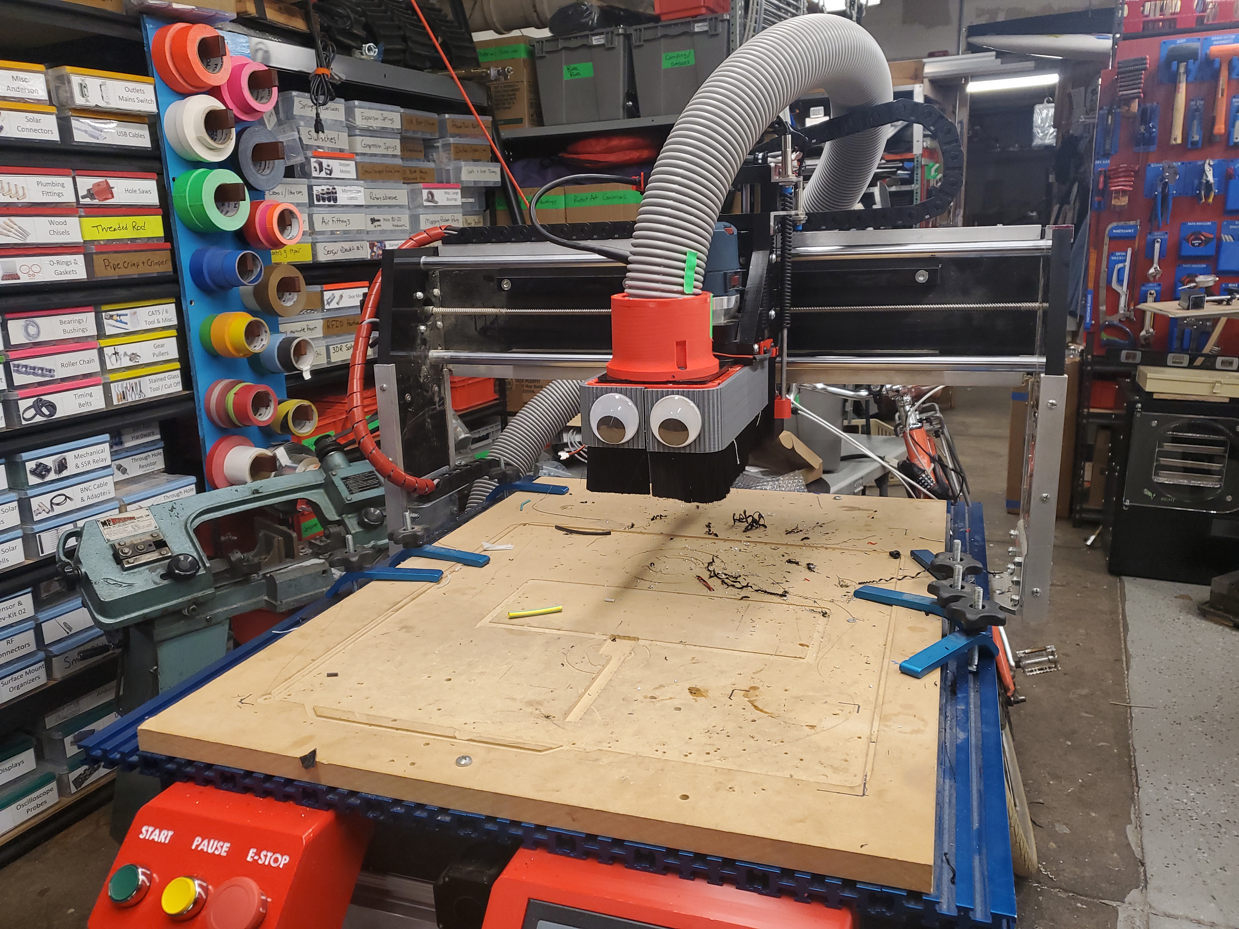
To get the dust from the spindle head out to the vacuum seperation system I opted to use a semi-flexible hose. Hose with printed spine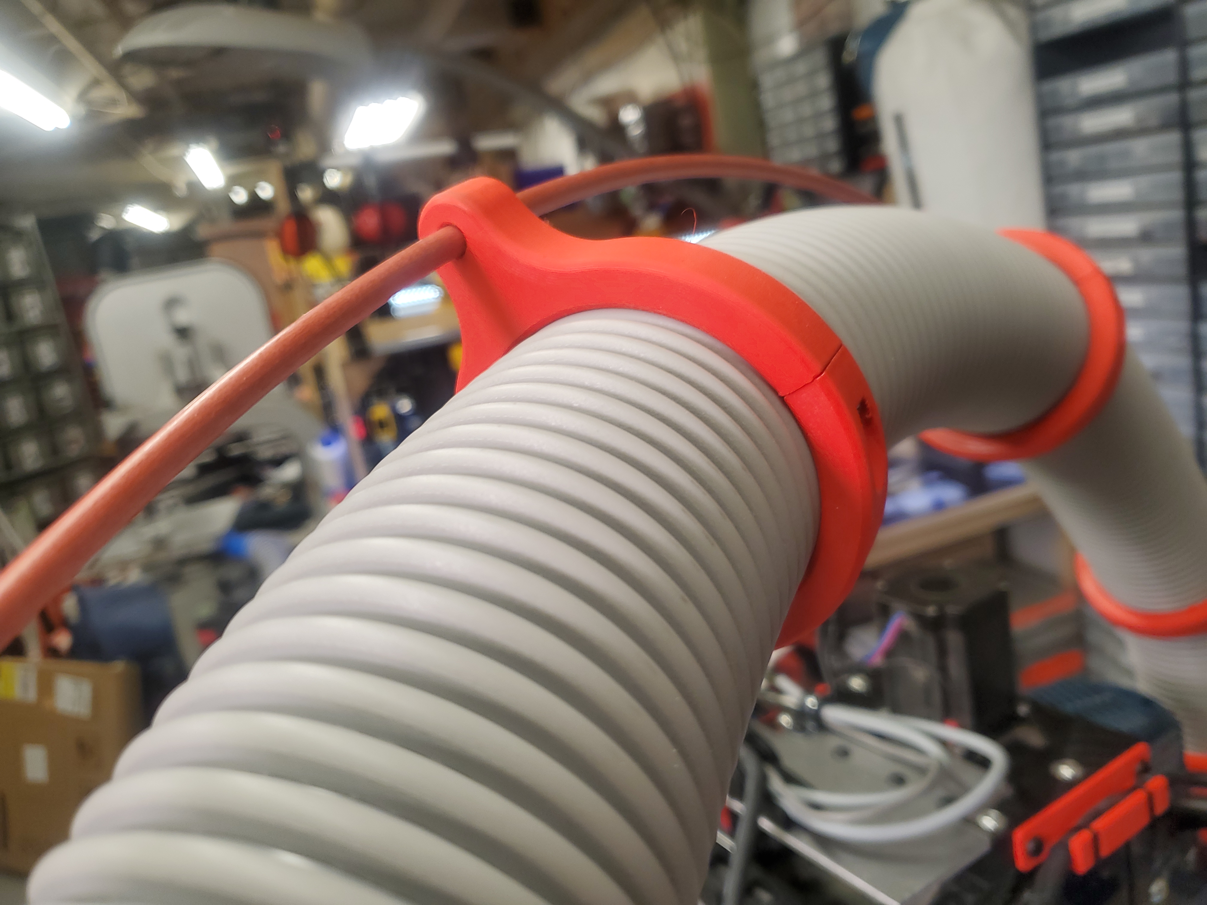
Next up is test fitting the dust shroud. The magnet mount on the tool, with steel barstock on the removeable brush dust guards worked remarkably well. I was debating putting the magnets on the dust covers instead, but managed to find enough space to fit it on the tool head. The brushed steel glued into the dust covers worked incredibly well. Assembled hose with printed spine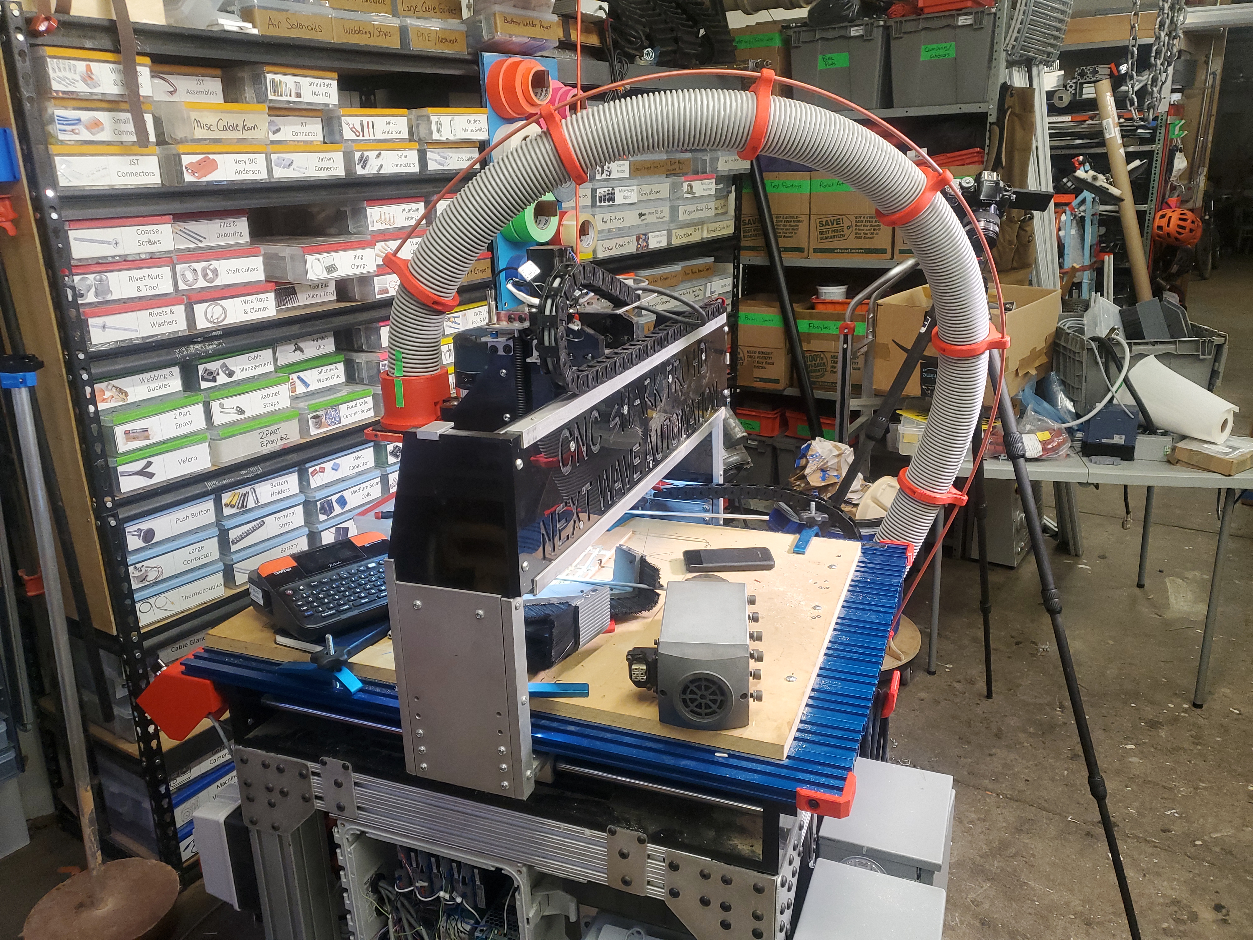
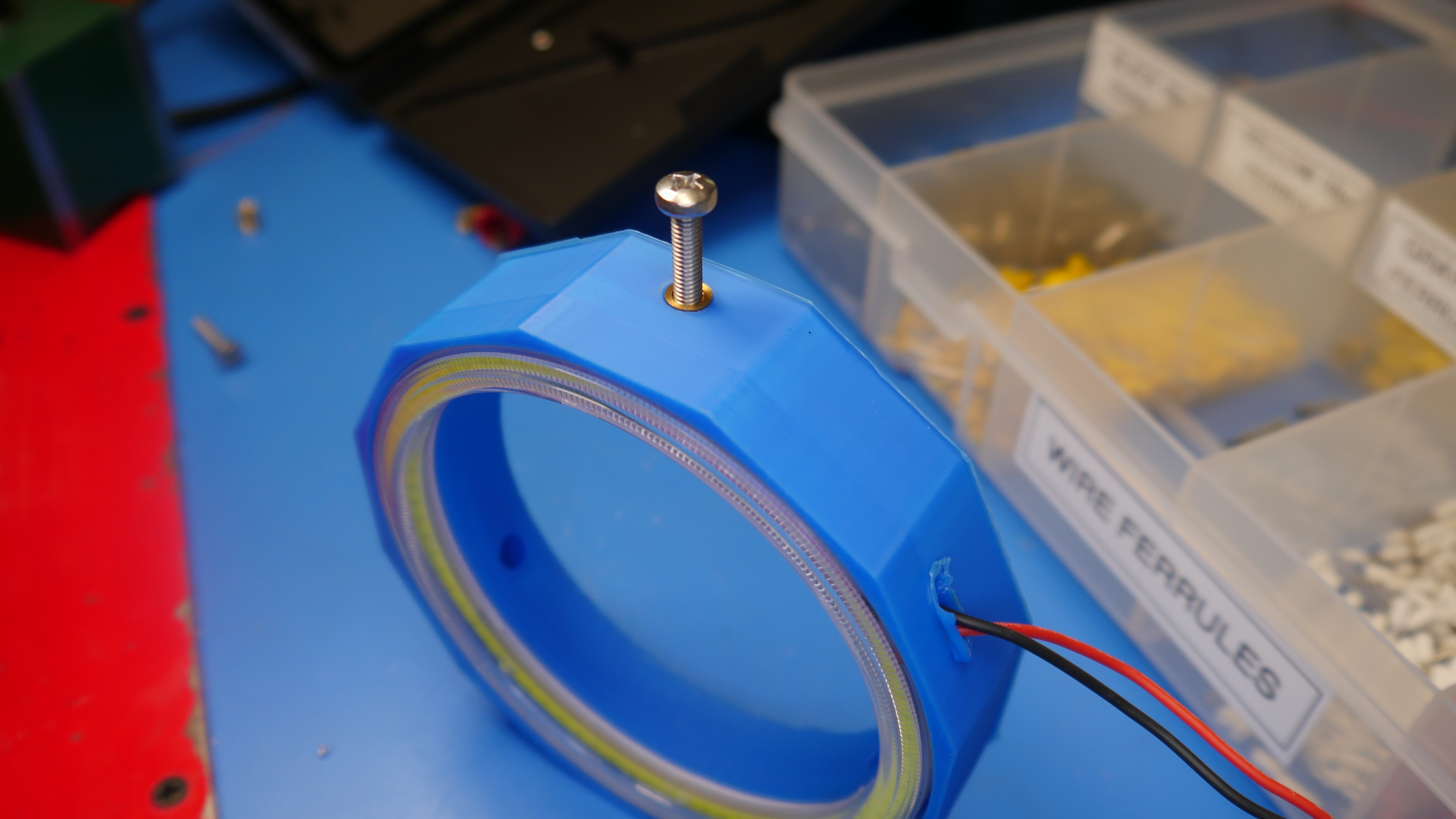
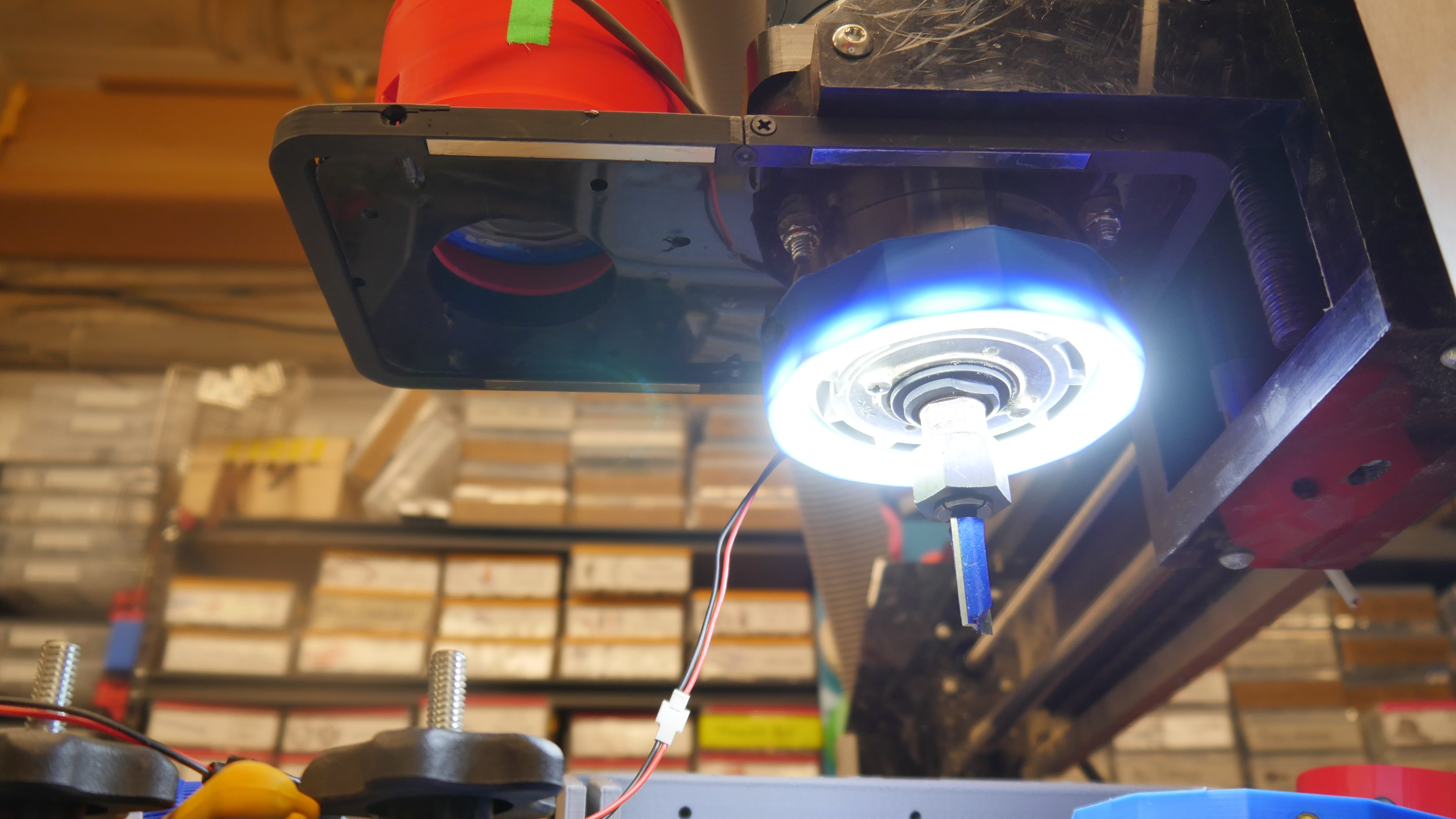
To attach the spine to the hose was fairly straightforward, with the plastic hose attached to the CNC, i went With the dust shoe covering up the spindle visibly, i wanted some indication of how the spindle was doing. The VFD does have an output that mirrors the VFD load (current) as a 0-10v proportional output. This add-on follows the spindle around, displaying live spindle load. It's a remarkably configurable automation direct display [link], that can take in process control 0-10v / 4-20ma inputs and display them on a live chart. It's remarkably configurable and really well implemented. I ended up opting to remove 2 significant figures and label the alarms, the clip shown below is a quick test using a bench supply to simulate motor load. The amazon headlight rings fit really well into the print. I opted for three set-screw mount points that clamp on the router / spindle. I neglected to leave space for the wires to exit the print and opted to just use a hot screwdriver to poke a slot for the cabling to exit. The double sided adhesive from the light did do a surprisingly good job bonding it to the print. I did add a small amount of RTV along the edge in the off chance the spindle vibrations shook it loose. 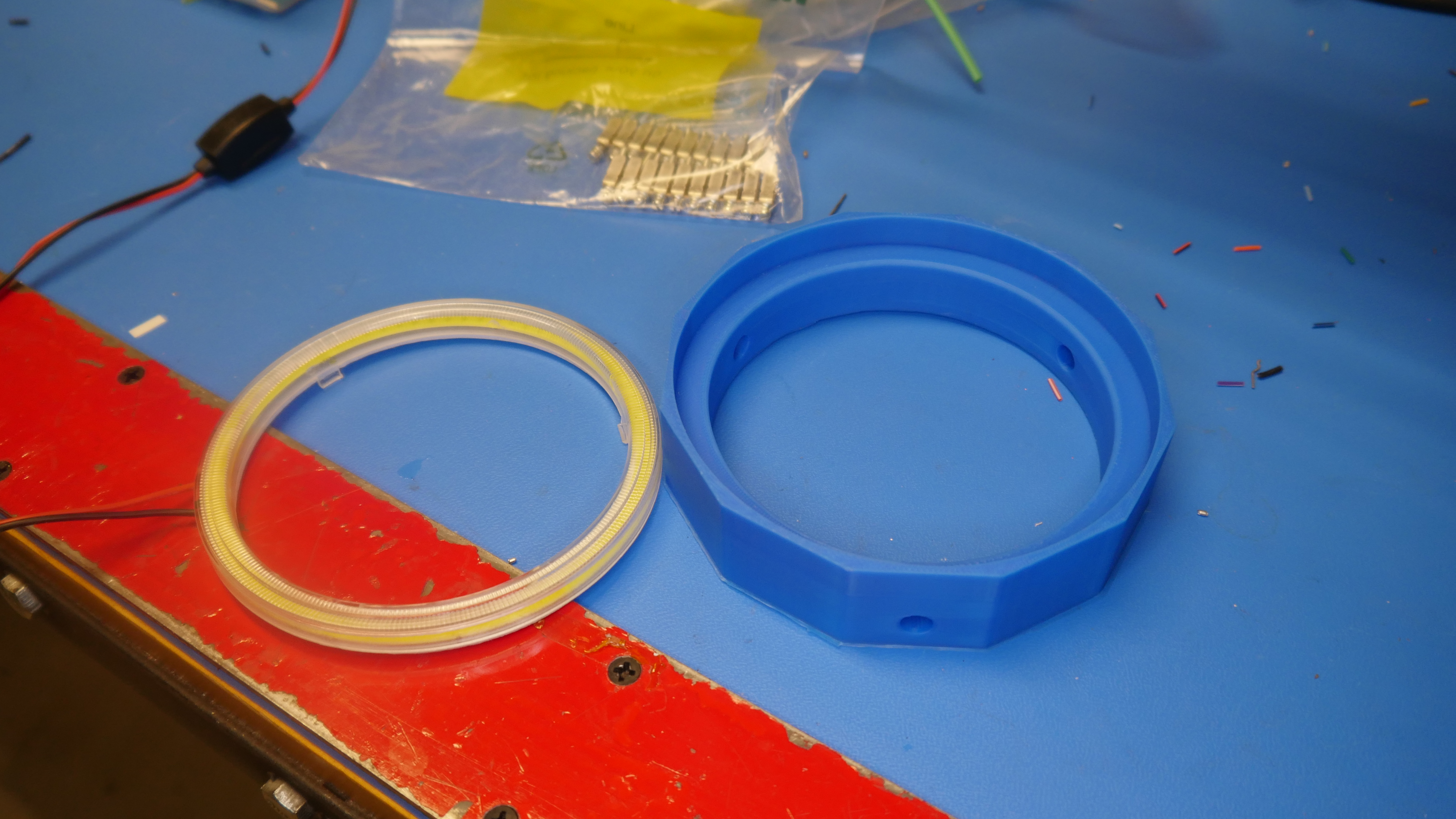
With the spindle light assembly complete, time to see how it looks installed and running fron the 24V bus. The illumination is great and overall it did not seem to get warm after running for a few minutes. It's not clear if the router chassis heats up during use but this is something that could periodically be checked if it becomes an issue. 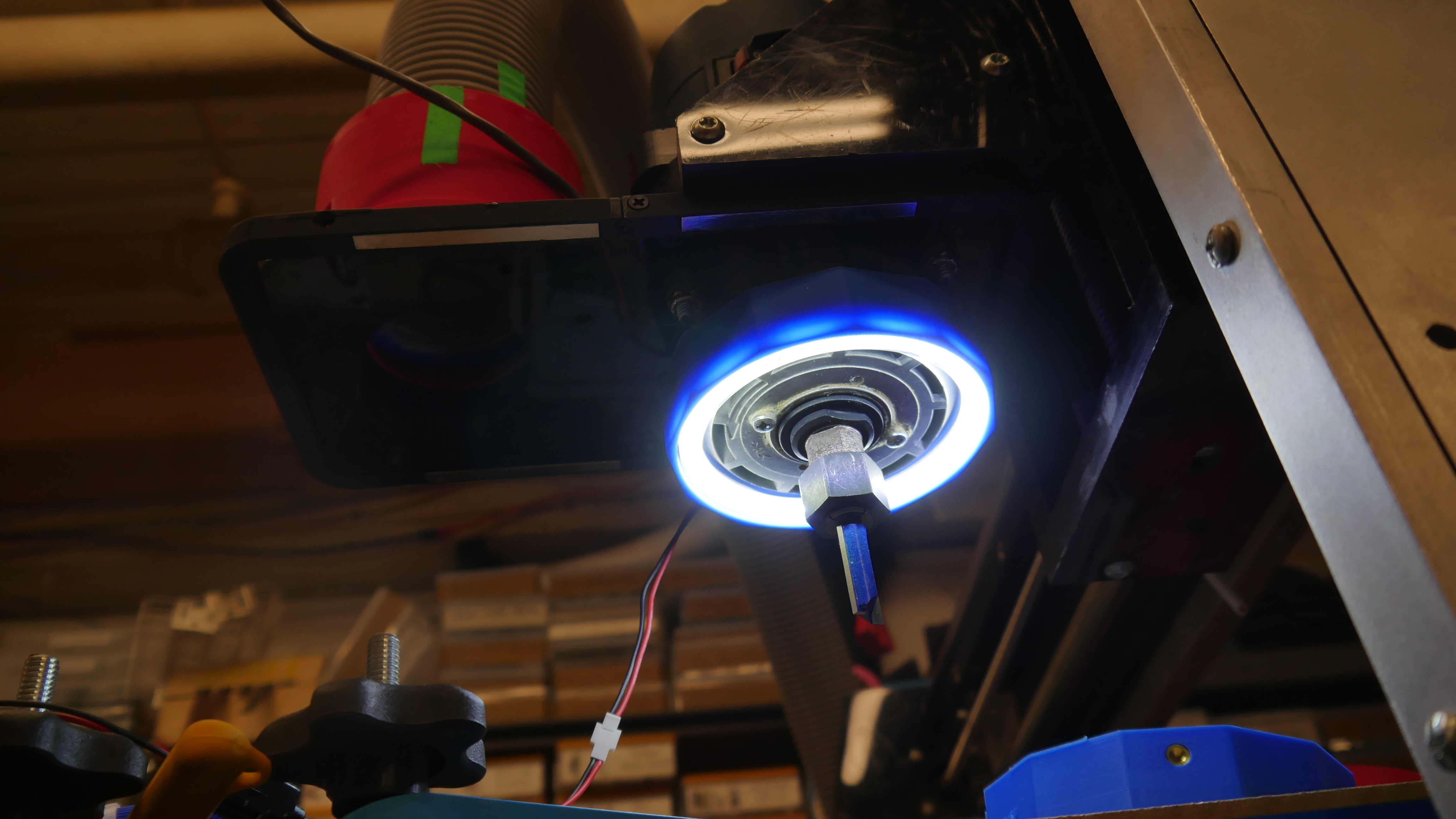
A quick magnetic pendant holderWe're getting to the final bits on this project, so it's time to find a place for the pendant to live. This pendant is fairly basic and comes with the controller kit, but it does have integrated magnets which is a nice bonus feature. I have some galvinized sheet steel left over so the plan is to use it, in conjunction with a print, to both attach to the 80-20 base and also magnetically hold the pendant in position. I went with my go-to thermal inserts + white paint pen style print for this one and it came out surpringly well. I've opted to go with the following procedure: Print part with text 0.03" inlayed, use a paint pen to fill in the lettering, sand off the excess when dry, then hit with 1 coat of acrylic clear coat. This helps keep the print surface clean-able and does really pep up the prints. Assembling the motion controlsWe know the stock controller supported 3 axes, at 3.5A stepper driver current maximum. As I'm building this from scratch, i'm opting to include a 4th axis for eventiually doing rotary engraving. This may be a bit onerous of an add on, but lets push to make it happen. I started with a 10x10" amazon hinged enclosure with a clear cover. A Din rail 24v 10A supply would feed the stepper motor drivers, and seperate small 24V din rail supplies would feed different parts of the controls system. 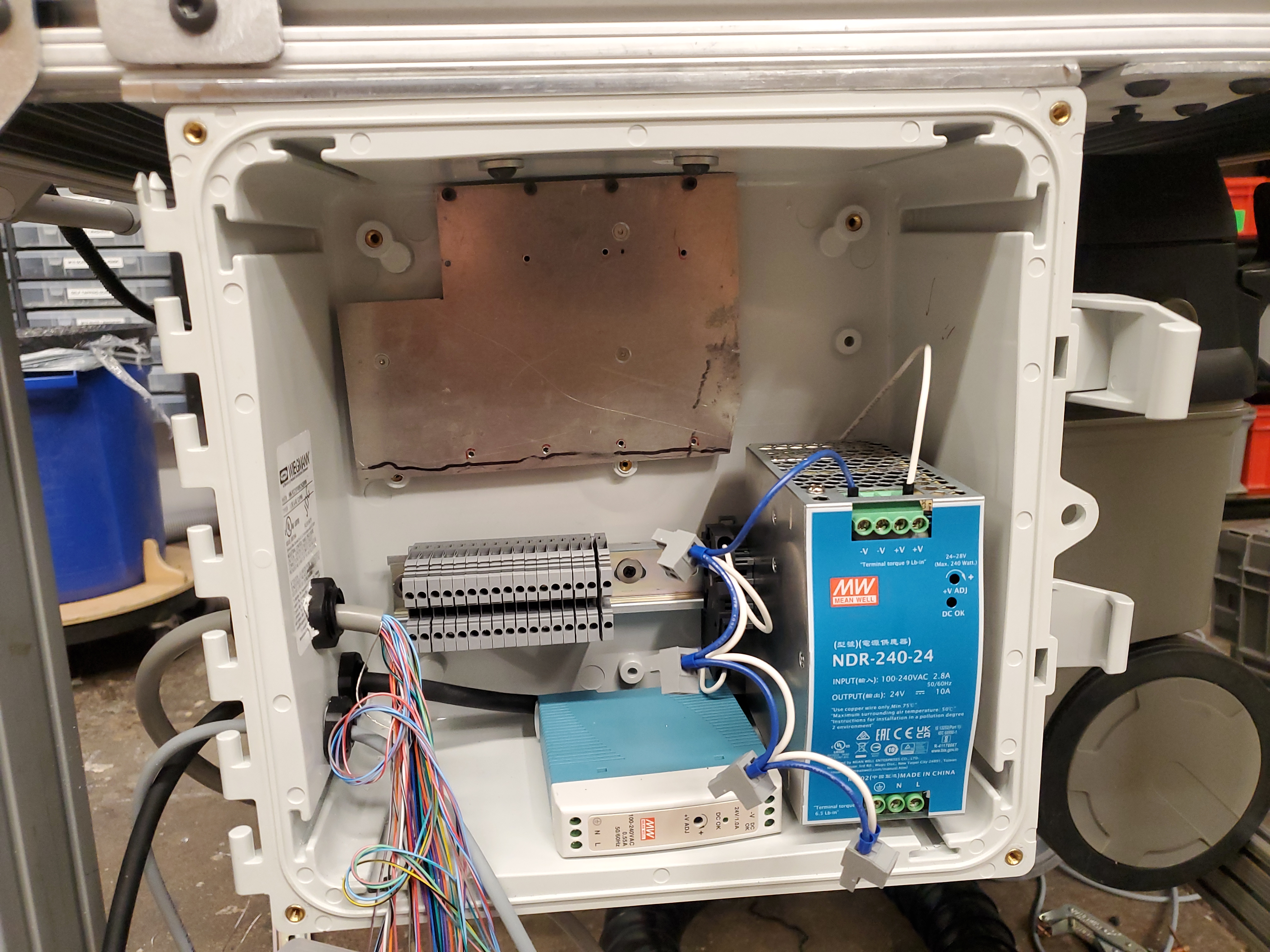
The plate at the top was a simple aluminum cut-out to provide surface that the motor controllers could mechanically attach to. I drilled and tapped respective M3 mounting points for the four stepper drivers. With the stepper drivers mounted, and taking up a lot of enclosure space, it was time to route in some cables. Each cable bundle entered the controls enclosure thru cable glands. 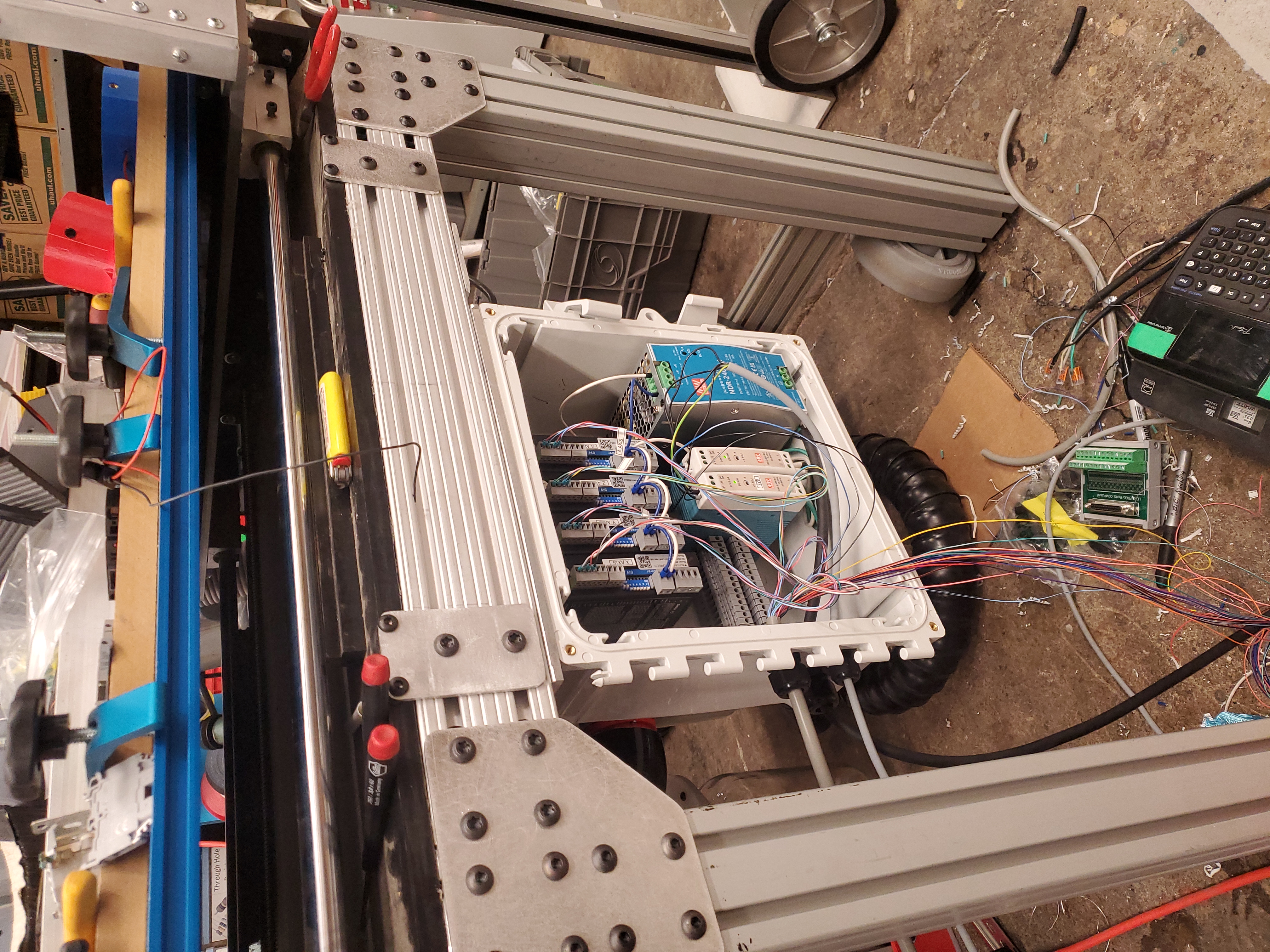
Concluding Remarks:
Have you noticed that there are no
advertisements or ridiculous pop ups?
|


Post your comments! |
|
Comment Box loading
|