
Dane Kouttron
Project Started: 05/2017 Reformatted: 01/2024
Adding some better lighting to a Bausch & Lomb 'Stereo Zoom 7'This is a quick design for a printed adapter for the Baush & Lomb stereo zoom 7 microscope, along with some details about the microscope. In the past I had tried out attaching an led strip to the bottom of miscellaneous scopes, to varying success, but the advent of low cost ring lights dramatically improves lighting for tiny IC's and re-flow work (no more shadows). 

|
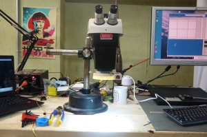
Quick Intro to the Bausch & Lomb 'Stereo Zoom 7'The Baush & Lomb series of 'big angry 1980's microscope on an offset heavy arm' are really quite excellent for SMD component install and soldering. They also commonly appear in laboratory clean-outs and industrial auctions. 
This one in particular came from a lab clean-out, and has seen some use. It was missing the eyepieces, but fortunately, they are standard. The ever-excellent Peter crafted some from the ether and lo, they work great. These use 23mm optic mounts, which are fairly common [amazon] [ebay]. There's an excellent tear-down thread [here] 
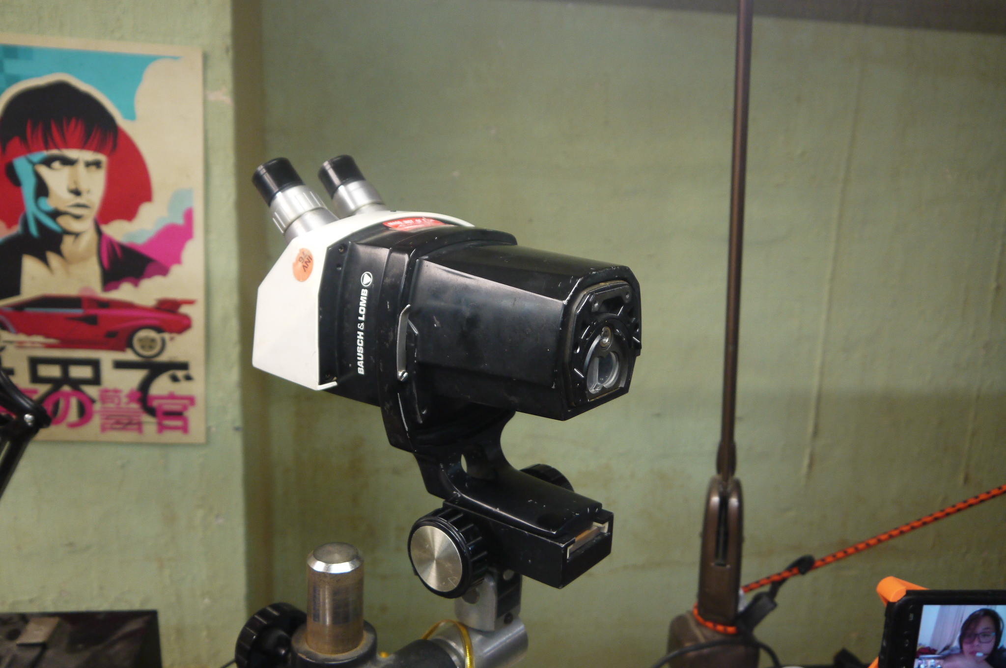
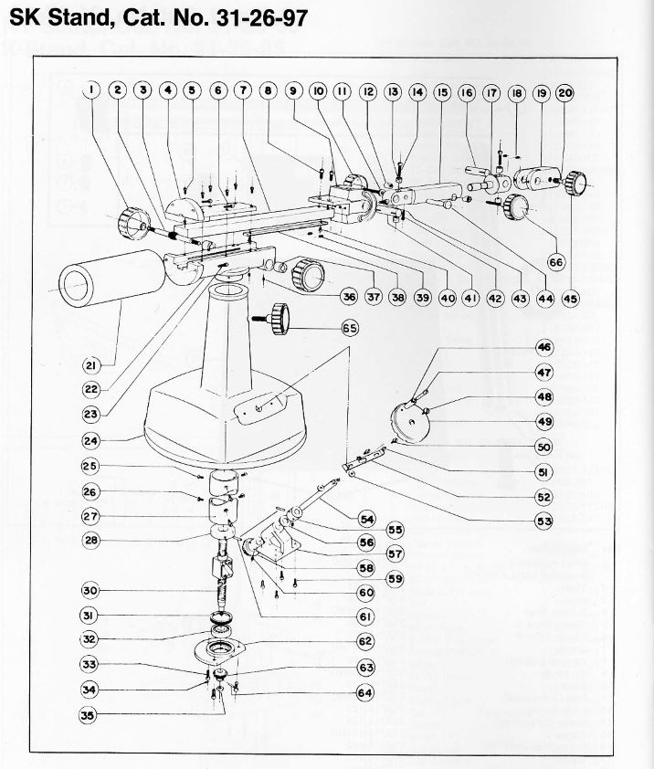
A copy of the series manual is available locally here [link]. This conveniently provides some excellent imagery into the innards of the microscope assembly. 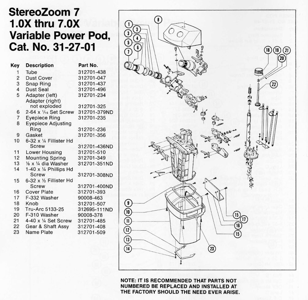
|
Ebay Ring Light and adapter |
|
There are a number of ring light adapters floating about the multiverse, I opted for this [link] one 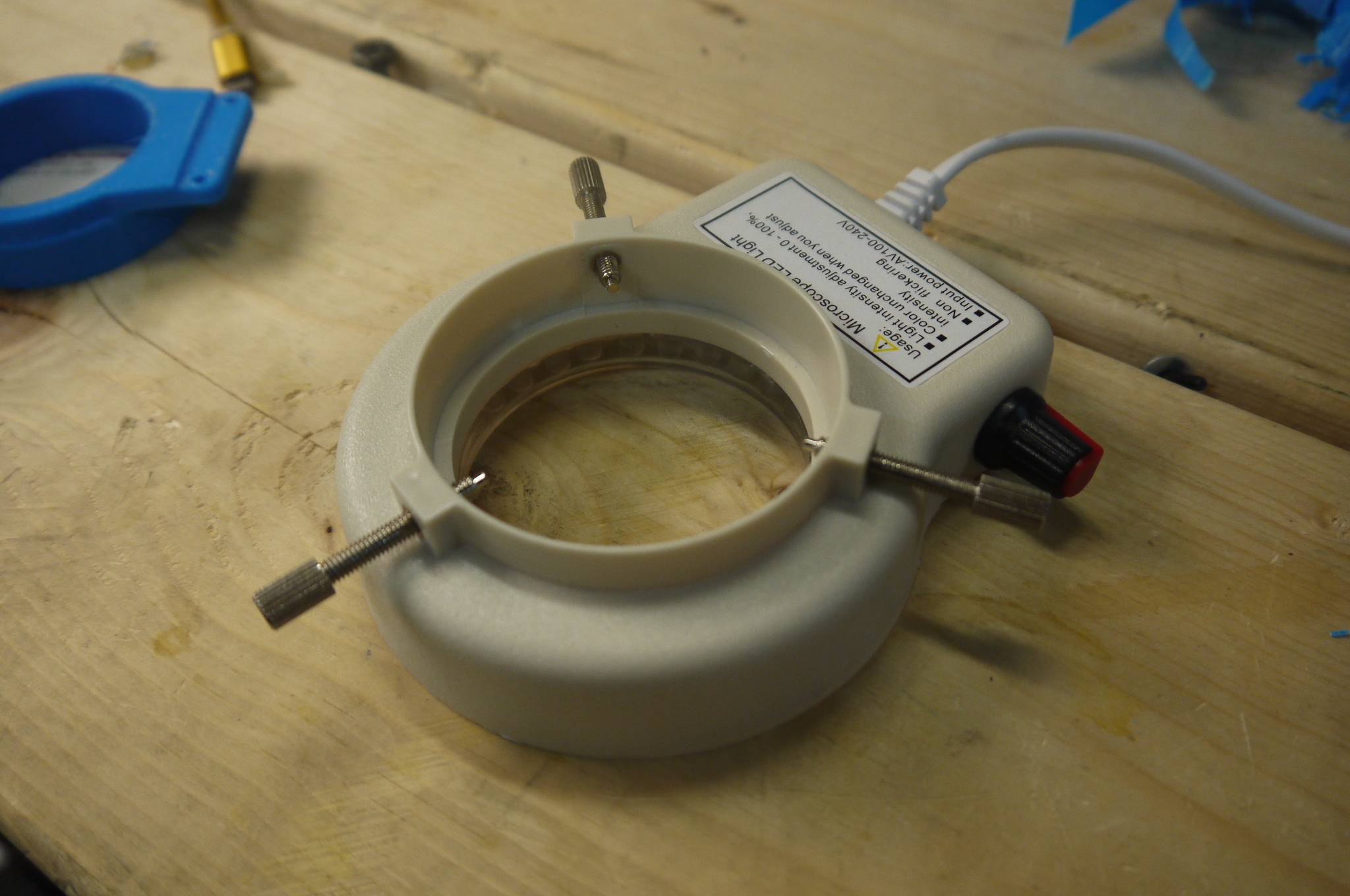
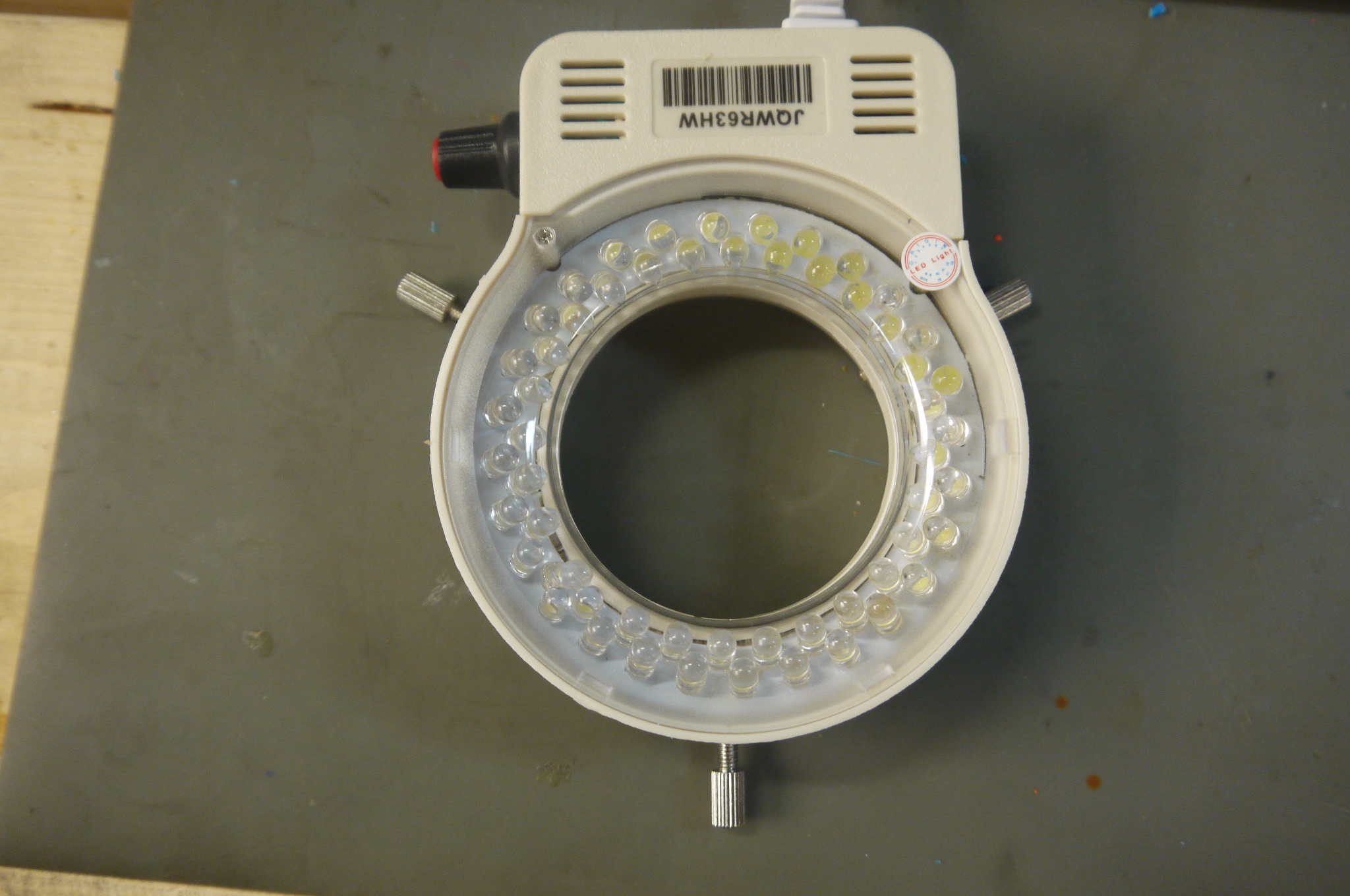
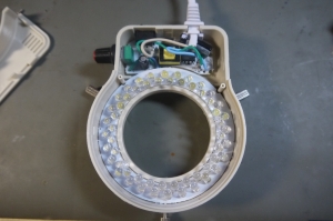
The innards of this particular led ring light are better than I expected. Normally ~5w mains connected leds use a capacitive dropper based supply [link]. While capacitive droppers do work, however, they are non-isolated and the giant-film-cap to drive the leds can be a bit bulky. I think, as this is marketed as a 110/220 mains adaptable supply, they opted for the tiny-switcher approach. Capacitive droppers also exhibit the 'quite blinky' issues. 
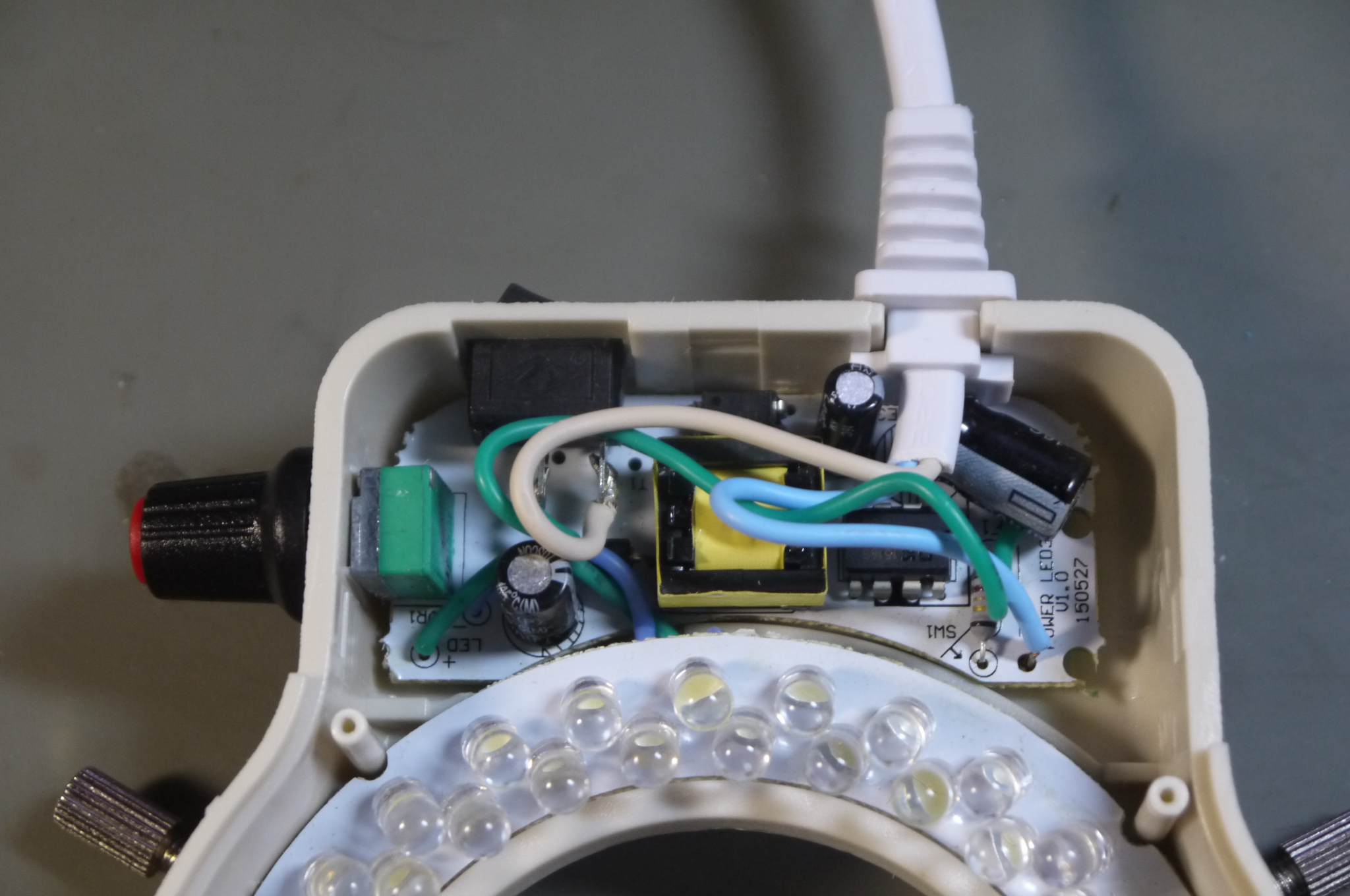
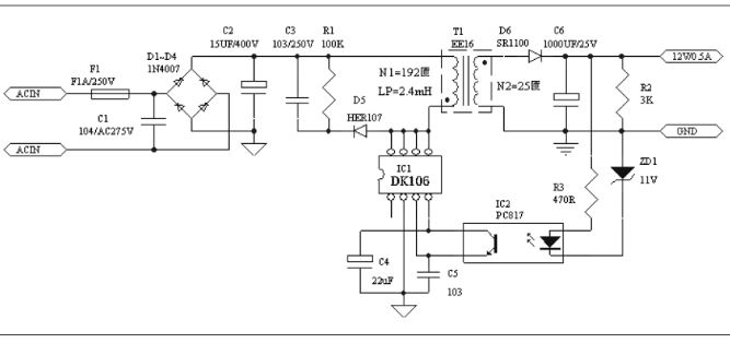
Yowza, its not just a capacitive dropper. The IC that runs the led driver is a DK106, [local link]. Its actually rated for 85-265vac operation, which explains the '110/220' capability. It runs from rectified mains and twiddles a transformer, using an optocoupler as voltage feedback. 
Its actually pretty bright too. The adjust pot is smooth and there is no characteristic 'low duty cycle flicker' which occurs on a number of dimmable things where their internal switching frequency, plus low adjust setpoint result in an increasingly viewable flicker. 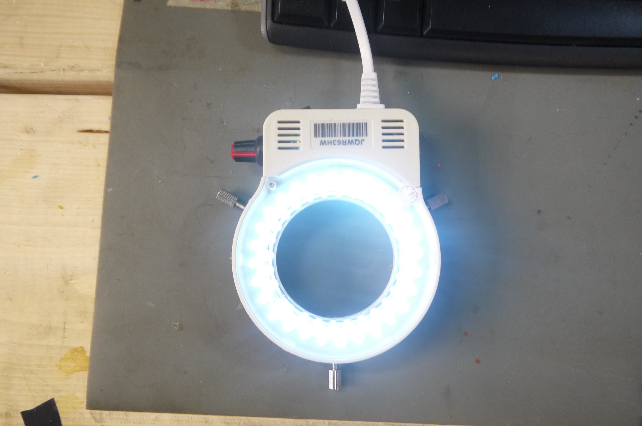
|
Printed Adapter |
|
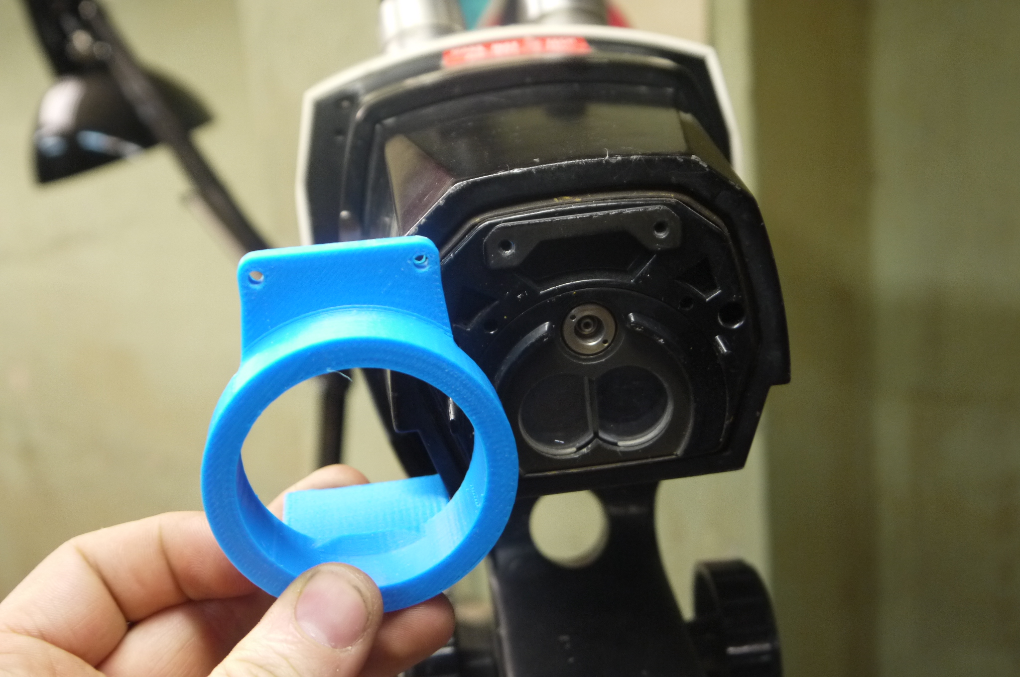
The Baush & Lomb was intended to have an external illuminator, or eyepiece based illuminator. The manual mentions a ring-illuminator, using a fluorescent ring lamp, but I'm not sure how that mates. Ah well, this is a quite-good job for 3d printed parts: Weird geometry, not super structural, and quick. 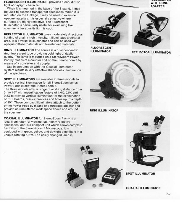
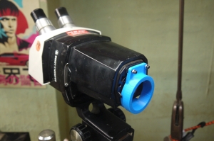
And with some hand-waving, a printed part appears. There's only really 2 screw holes to pickup on the bottom face of the microscope, both 4-40 thread. I opted to under-size the ring mount such that the screws had some travel into the ring to grab the part. The large flat surface is for doublesided tape / hotmelt glue to add some extra holding force to the scope adapter. 
TADA 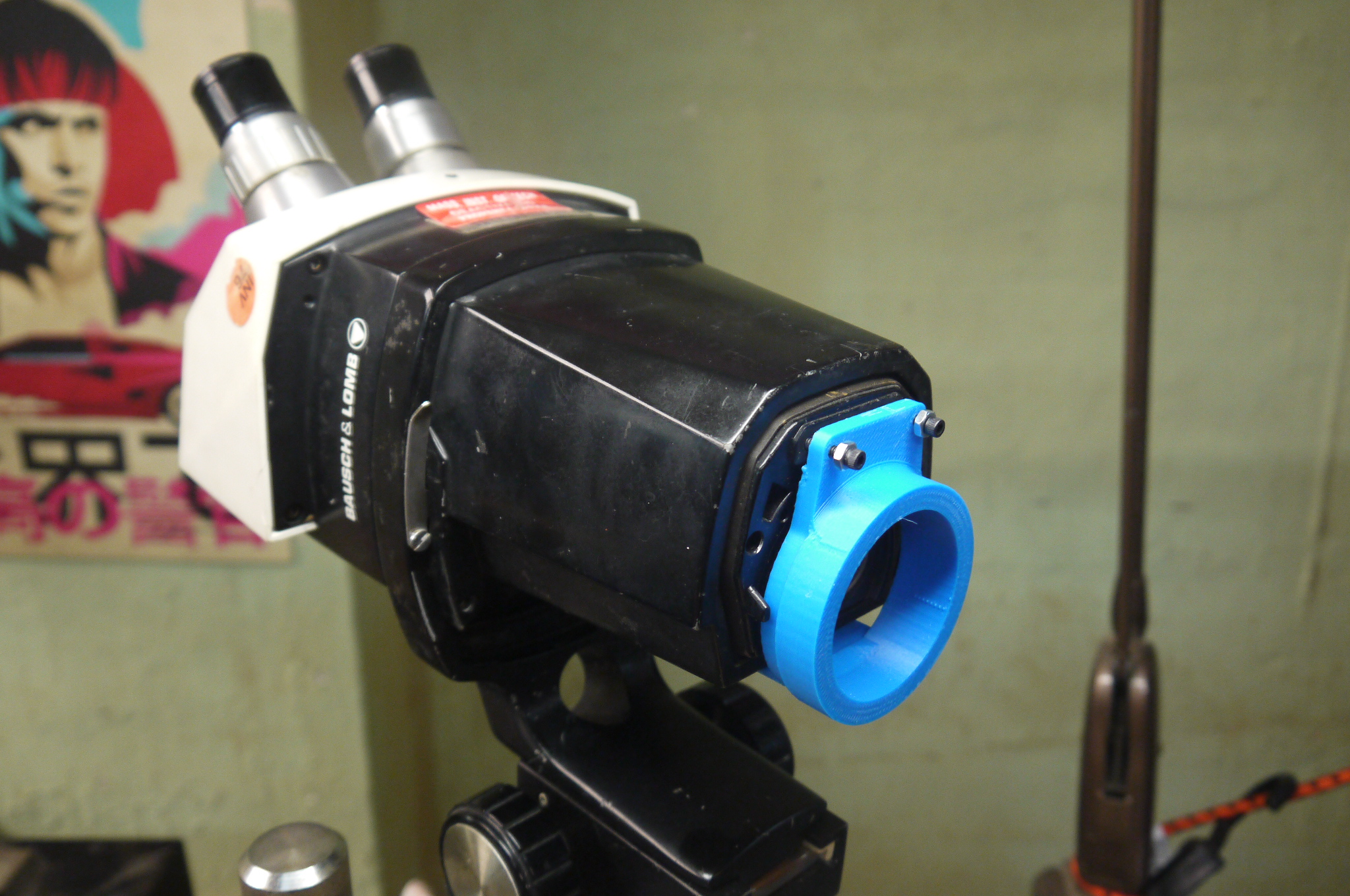
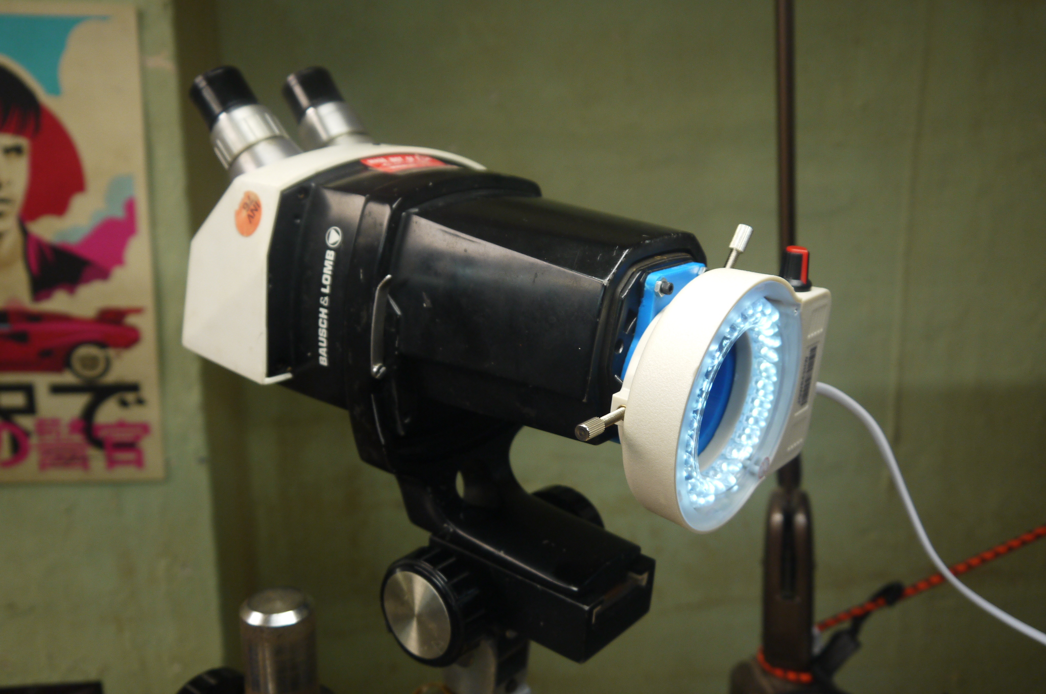
The 4-40 screws I had on hand were a bit long, so instead of playing games with a hacksaw, I added an extra 4-40 hex nut to take up the extra space. 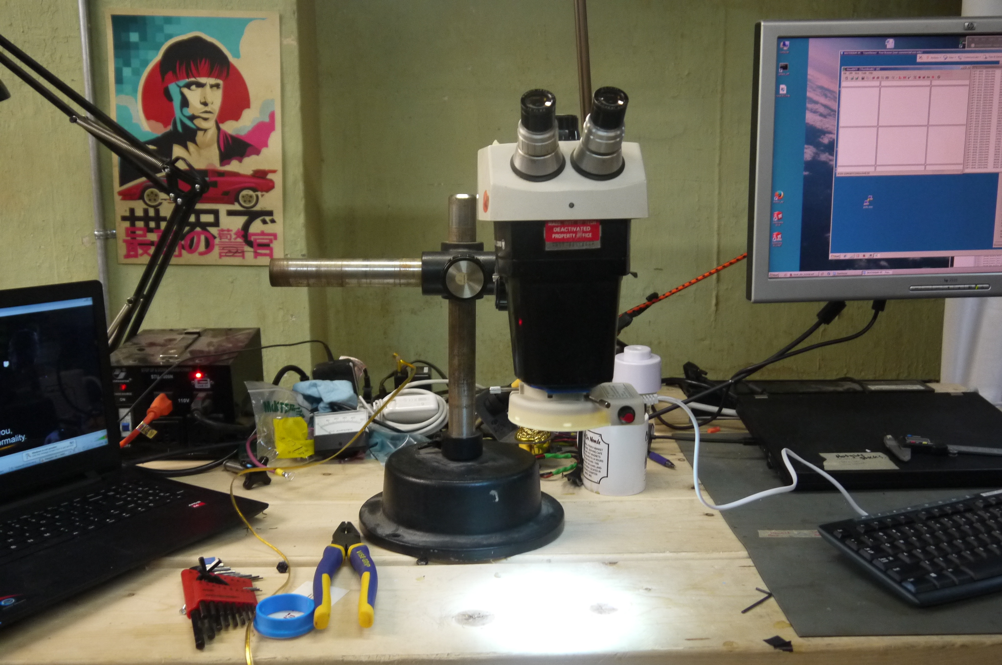
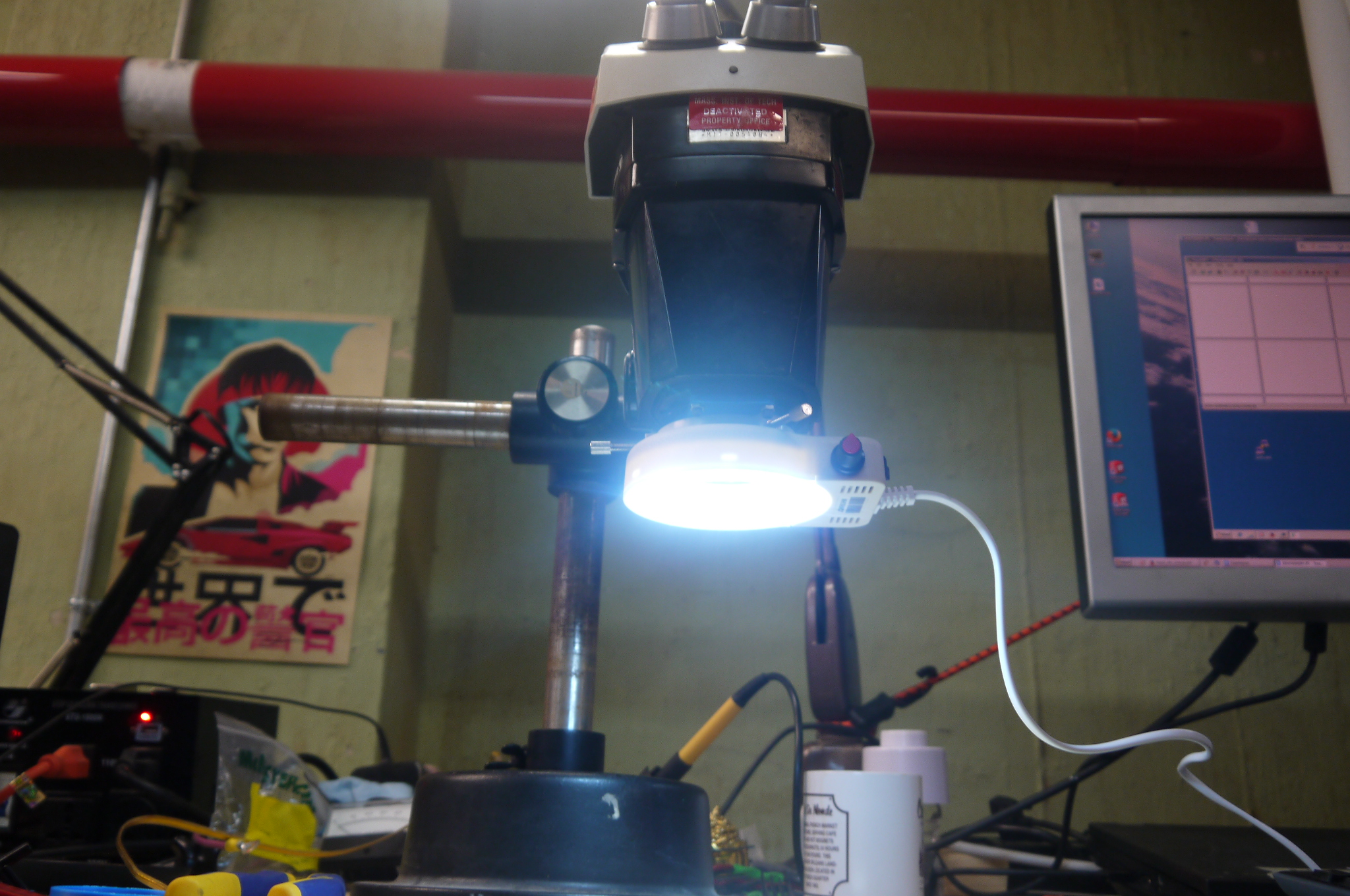
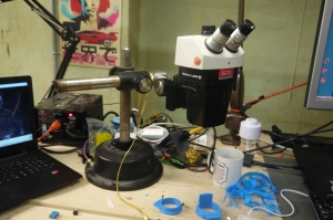
This leaves the brightness adjust pot right in the front, with the on/off switch to the side. 
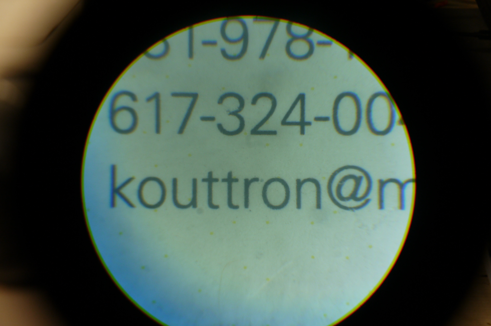
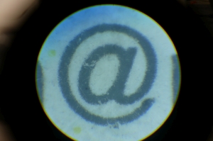
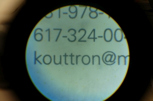
This was taken with a Panasonic GF-3 pointed at the normal eyepiece optic, but yes, the illumination works great. Shown is an Atmega 16u2 and a business card with tiny font. |
Solidpart files |
|
Here are the cad files for this printed part. I used an UP! Mini to print the part. Download below! 
[Solidworks 2014] 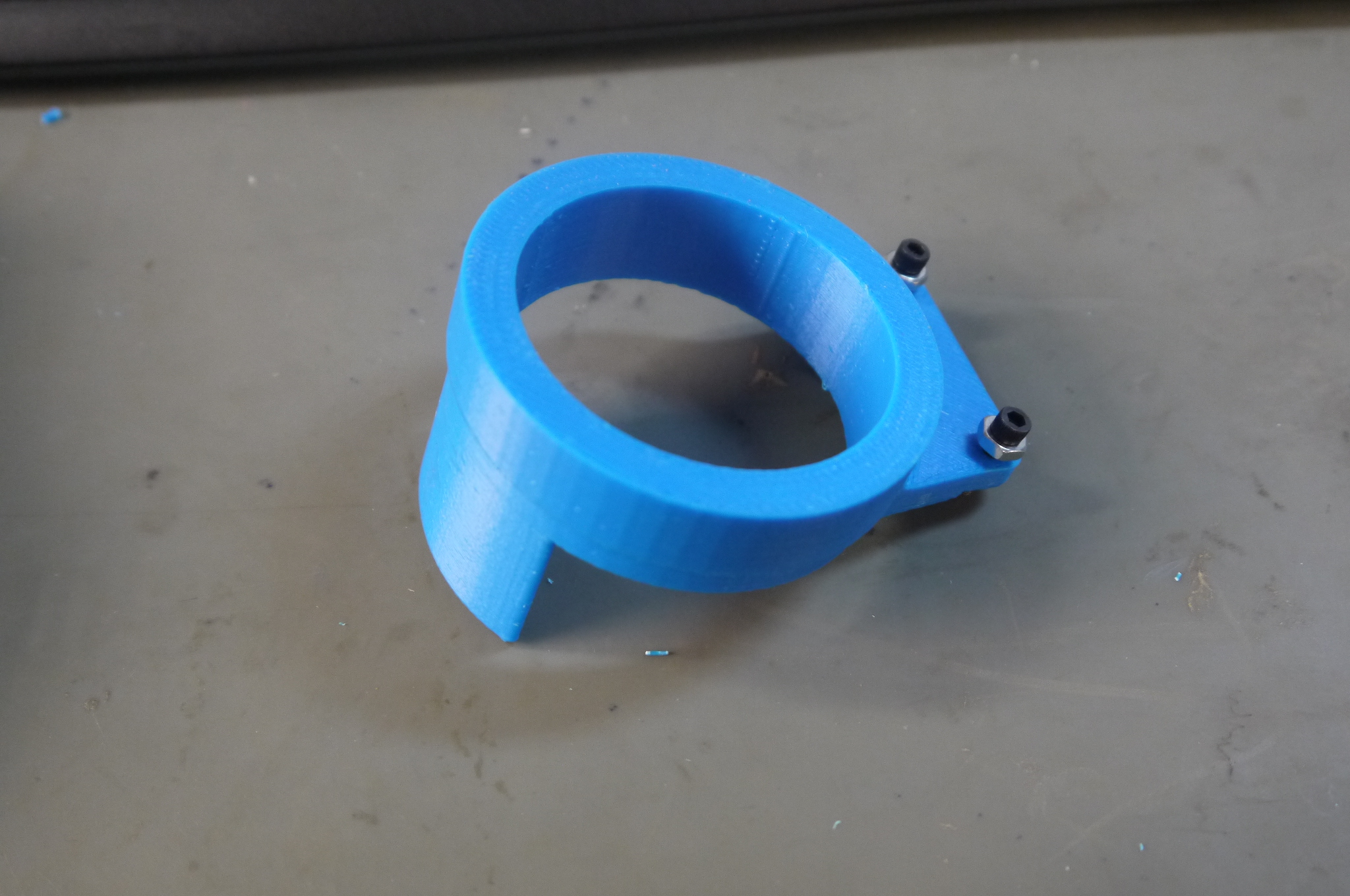
|
Want More?
There's other photos in the photo gallery
Post your comments! |
|
Comment Box loading
|