
Dane Kouttron
This project / write up is in progress, check back for more soon!
Project Started: 06/2024

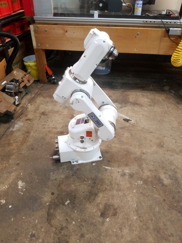
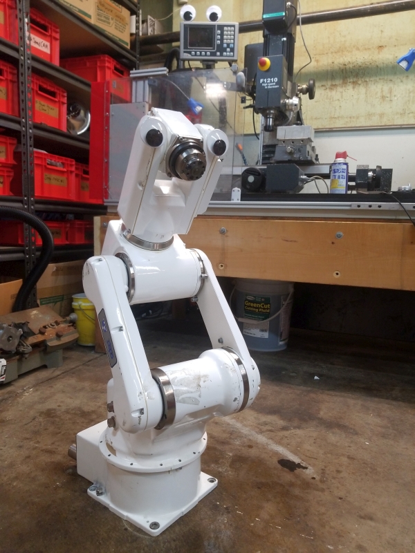
This little robot hitchhiked across the country, lets wake it up and teach it to paintSay hi to an adopted AdeptSix 300CR, a six axis robot arm that's table-top size, but has industrial capabilities. This particular robot traveled from California to Massachusetts in the ever excellent Aaron's cross country car trip. It was born in November of 2003, so it is well outside of the normal service life / support life cycle. These kind of robots are interesting. Without the controller hardware they are nearly free to purchase, the whole controller + robot however is quite expensive. Lets try to wake it up without spending too many rubles. I learned a lot from three axis SCARA style machines in the past, this is my first six-axis arm, and it's too frigging adorable. |
An overview of the planThe plan is kind of simple: Figure out what options exist for the hardware controls of this little guy, and once 6 axis hardware control is available, begin looking at applying ML for brushstroke generation. As the robot is not inordinately huge, it can be ported to a mobile platform (like a cart), ideally run off large storage batteries and brought to events like farmers markets or technical fares like open sauce. It is fairly speedy, so it is possible We do have some reasonable technical specs of the robot itself, max 3 kg load on the end effector, which is plenty for a paintbrush and some pneumatic hardware. ± 0.020 mm repeatability for position which is stellar if its actually achievable. The stock controller lists 1.5kw as the max power rating, which is a bit higher than I would have expected, but that likely includes the support computer and early 2000's control hardware. The arm itself only weighs 30kg and has the following speeds listed per axis: Maximum Joint Speed:
Taking a look at the ManualThere's a few problems that need to be sorted, given that this is an early 2000's robot, all the control hardware would only be available surplus. This can become a pricey trap, as control cards, servo drives and all the specific custom hardware can add up. The next part is, with an early 2000's robot hardware setup, what is the software interface? If the result of acquiring all the pokemons is some terrible java interpreter or windows XP application, that's not really a great option either. What is the ideal interface for something like this project? That's also a good question. I like separating the hardware kinematics from the higher level functionality, as that should be fundamentally higher bandwidth, with the higher level controls operating in a coordinate space, while the lower level controls the acceleration boundaries. So the first step is to find every manual and technical diagram we can to make some educated decisions. We're starting with the model number. 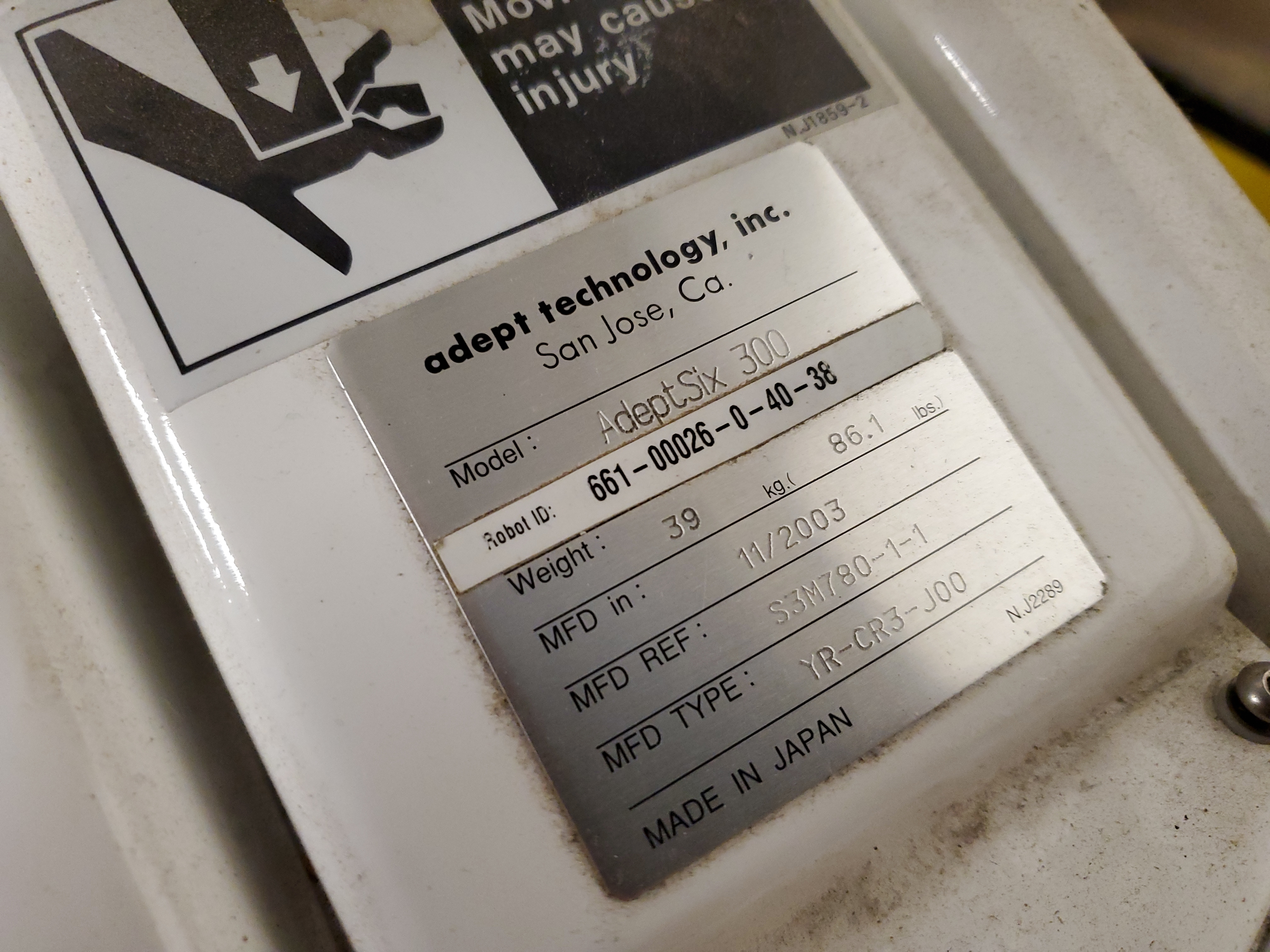
Adeptsix 300 Robot Manual RepositoryFor whatever reason these were not detailed directly from Adept so I am hosting these locally: 300CR Instruction Handbook:[Link]This is a 106 page manual that details everything from physically mounting the robot to cable interconnection. It also details everything about axes movement to moment of inertia limits. It does not give us exact cable pinouts, but it does give us a hint on the auxiliary connections, for instance you get 9 wires for end of arm tooling signals. We also learn that each axes has a battery backup for absolute position [page 85] PA-4 Power Chassis User Guide:[Link]This is a 62 page manual detailing most of the functionality of Adept's "servo box". For all intents and purposes this is a chassis that accepts three power modules and one communications module. Different "AMP's" can plug into the chassis so the same chassis back plane can run multiple robots. The dual output amplifiers allow for six total axes of control. It looks like i would want three of the "E" style amplifier cards for my model robot and then a "MAI-2" robot control module card to govern these. This is starting to look like an expensive Easter egg hunt SmartController User Guide:[Link]This is a 160 page manual of a module that goes in between the PA-4 power chassis and a normal computer. It connects to a host PC over FireWire 😅. It also uses a lot of custom cable assemblies to mate to external hardware, like the pendant, which i also do not have. Reading through this manual is pointing me towards just building a controller from off the shelf hardware and a MESA card, which should be cheaper and at least completely duplicate-able and easier to understand. We are going to need to find some pinouts though for interfacing to the machine directly. Adept Yaskawa 2BC Power Cable:[Link]So i contacted Adept via academic intentions and got some rough photocopied images of the cable assembly drawings for this machine. It is curious that this is also cross-listed as a Yaskawa robot, it may be possible to find some more hardware details by contacting them directly as well. Adept Yaskawa 1BC Signal Cable:[Link]I was also able to obtain this drawing which is the signal routing. It's a bit hard to read and the labeling is multi-language but it is probably enough to work with. I have no idea what the mating connector actually is, which is going to be a struggle to find but we're on the right track. Does this thing have any siblingsSo we found out from the internal wiring drawing that the cable is cross compatible with a Yaskawa SVX 300 Series 6 axis robot. What is that machine and who else re-branded a Yaskawa 6 axis arm? Maybe parts are more available from other vendors who are re-labeling the same imported machine. 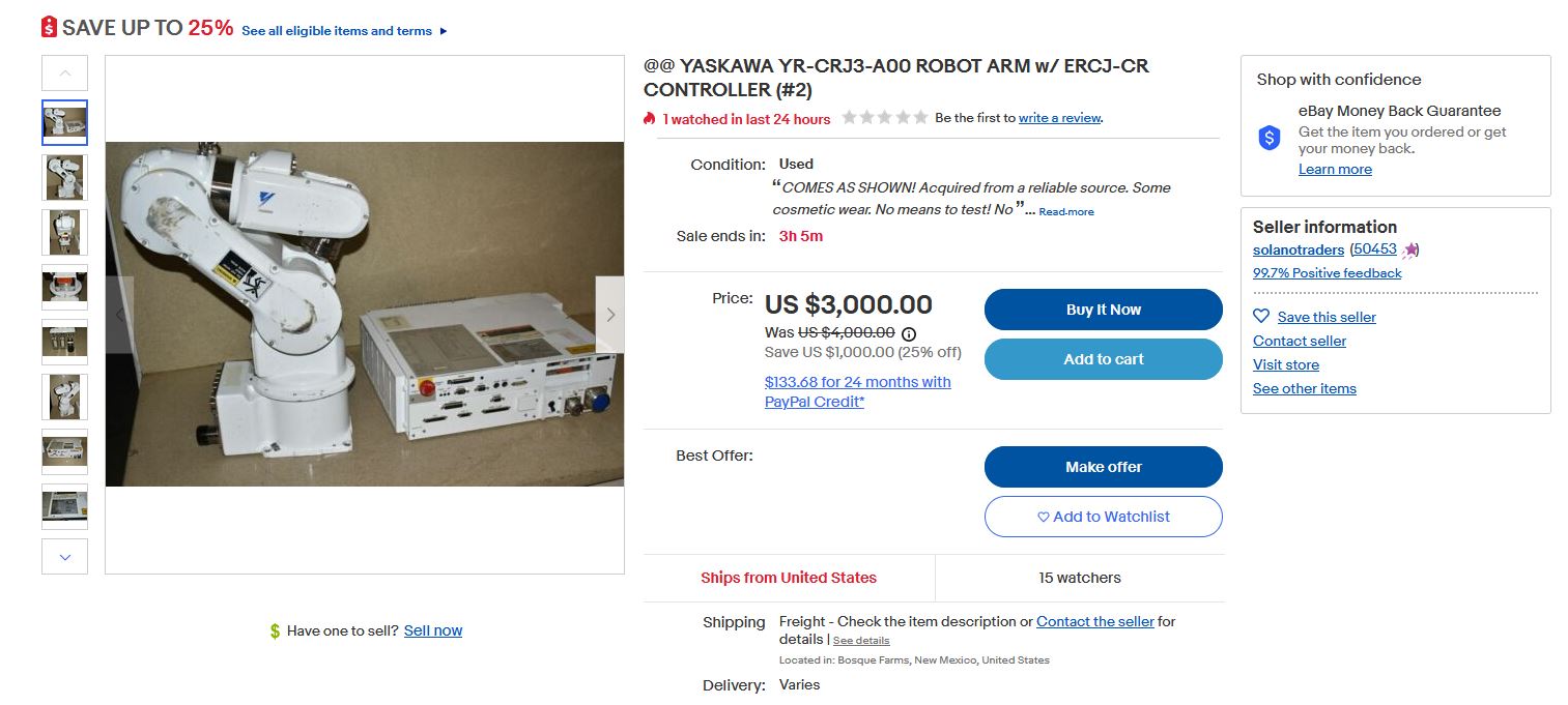
We also can see this Motoman robot is nearly identical. Lets jot down some part numbers. 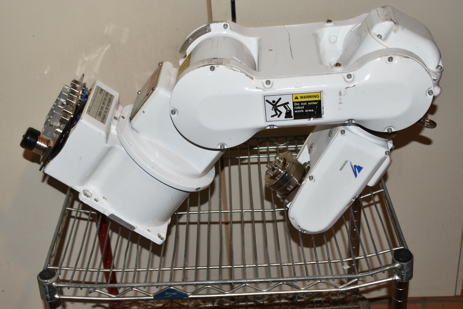
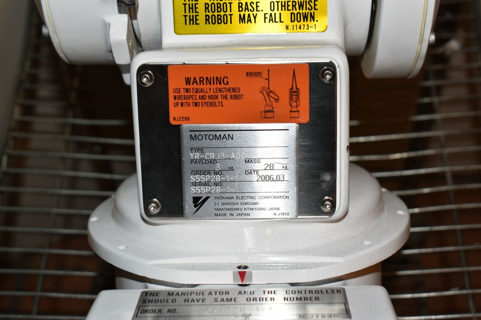
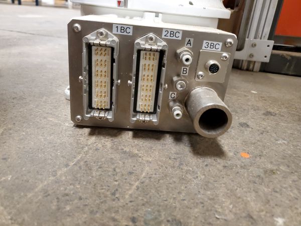
From some quick hunting, we find that the Yaskawa YR-CRJ3-A00 robot arm certainly looks the same on the outside as our adopted adept machine. So we have the following robots with similar hardware: AdeptSix 300, Yaskawa YR-CRJ3-A00, MOTOMAN YR-CRJ3-A00. Surprisingly neither of these two machines have any useful public documentation which is fairly surprising. What is this connectorFrom the rough wiring diagram we do not get the actual connector part number and the connector itself does not appear to have any vendor markings on it to give any hints. We only have the rough pin-out for 1BC and 2BC. 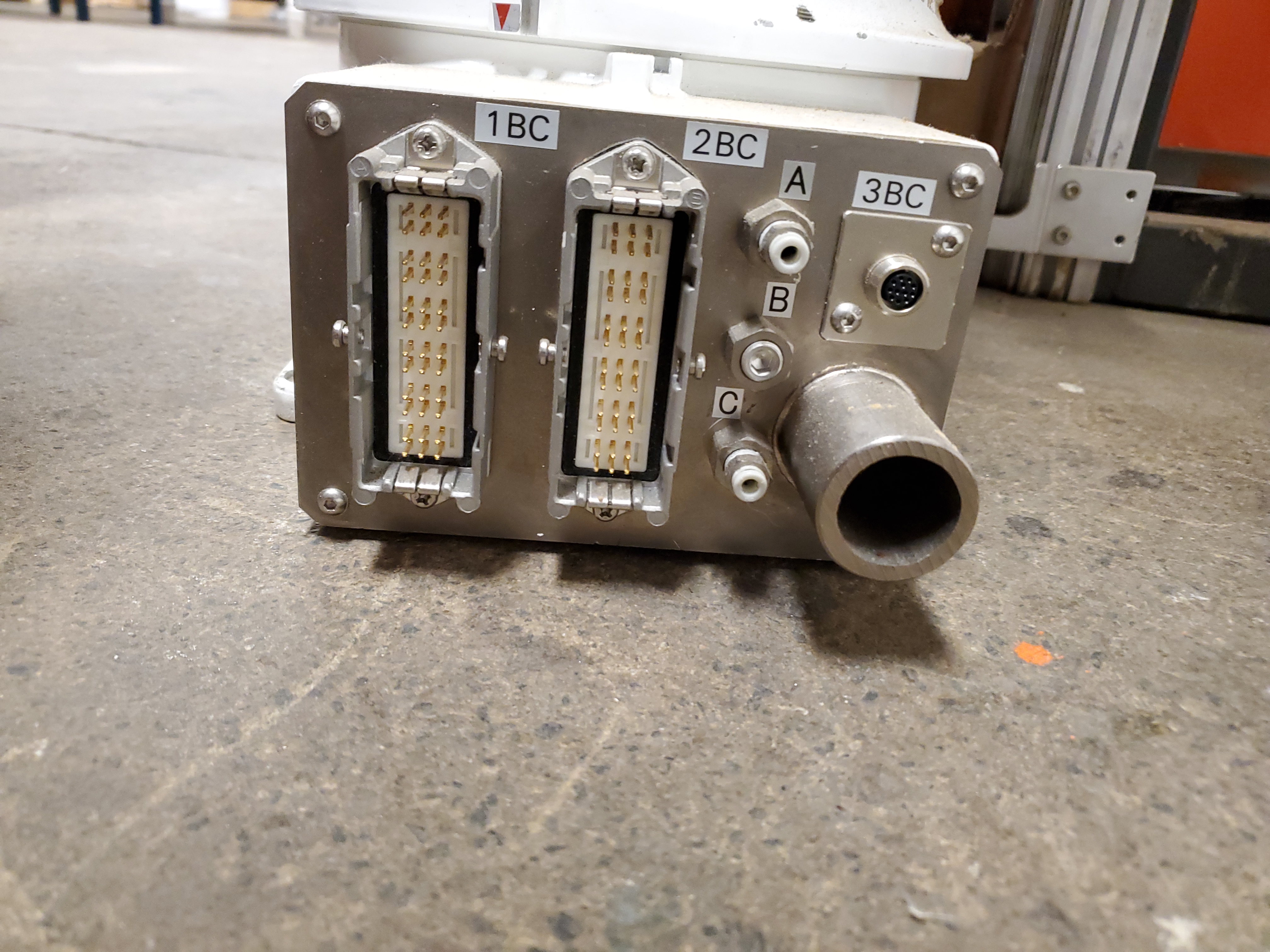
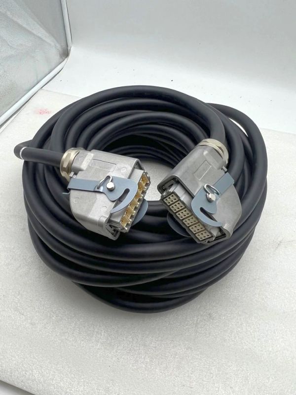
I was able to find this mating connector cable assembly, which does have somewhat a part number, from ali-express. It does have the correct arrangement of pins: 6 groups of 6 conductors, but the price tag is a bit absurd. Let's keep digging to see if these exist somewhere else. 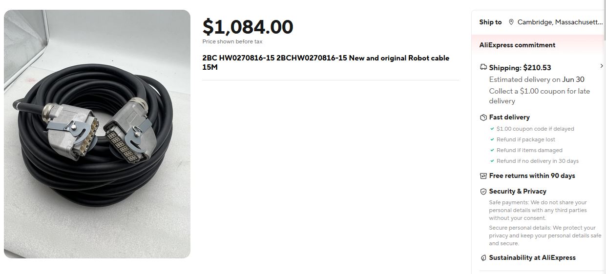
We can somewhat learn more from this ali-express posting however, here is the zoomed in version of what i think is the mating connector, shown below. 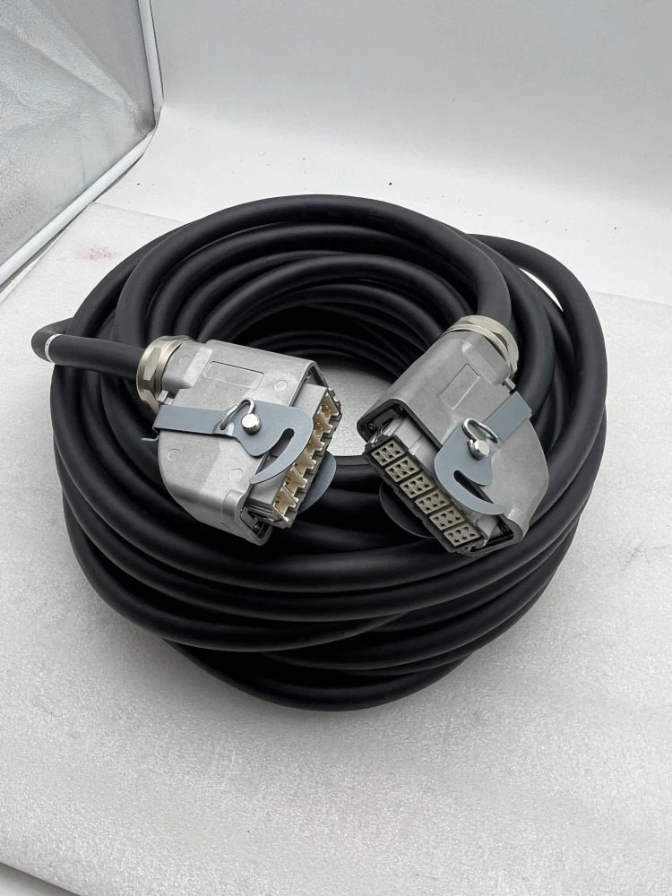
Lets start hunting for pre-made cable assemblies and work from there. Also document this clip https://www.youtube.com/watch?v=d2nGFFeyxAQ 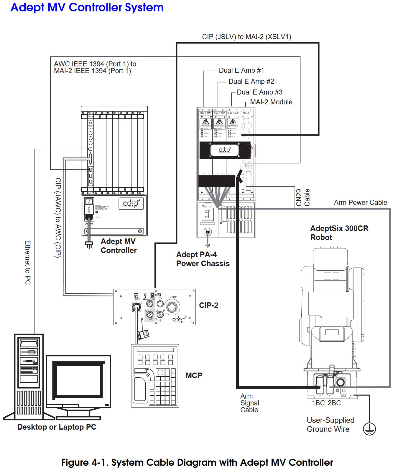
It looks like the PA-4 Power Chassis needs three dual-output amplifier modules, and then an MAI-2 Module, which we need to find out what that is. Finally the MAI-2 module yells at some form of a computer, or the Adept MV Controller via Firewire. This is going to be curious to wake up. Hopefully There's a way to interface with the MAI-2 module with a modern computer. Firewire is going to be curious though. Concluding Remarks:
Have you noticed that there are no
advertisements or ridiculous pop ups?
|
Post your comments! |
|
Comment Box loading
|