
Dane Kouttron
Project Started: 07/2009 Reformatted: 01/2024
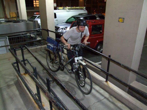
It's 2009: let's build an electric bike from scrapAn electric Car would be Sweet. I got to play with all sorts of electric and hybrid vehicles over @ GM last summer, but affording one is another thing entirely. This project revolves around building an electric bike from scratch, paying as little as possible while having a range of ~40 miles. A friend built an electric motorcycle, its awesome, and I needed one, albeit less motorcycle more bike. Being able to tool @ MIT made this all the more possible. Can it survive the trip between Deka [Manchester, NH] to MIT [Cambridge, Ma]? |
Project Planning Time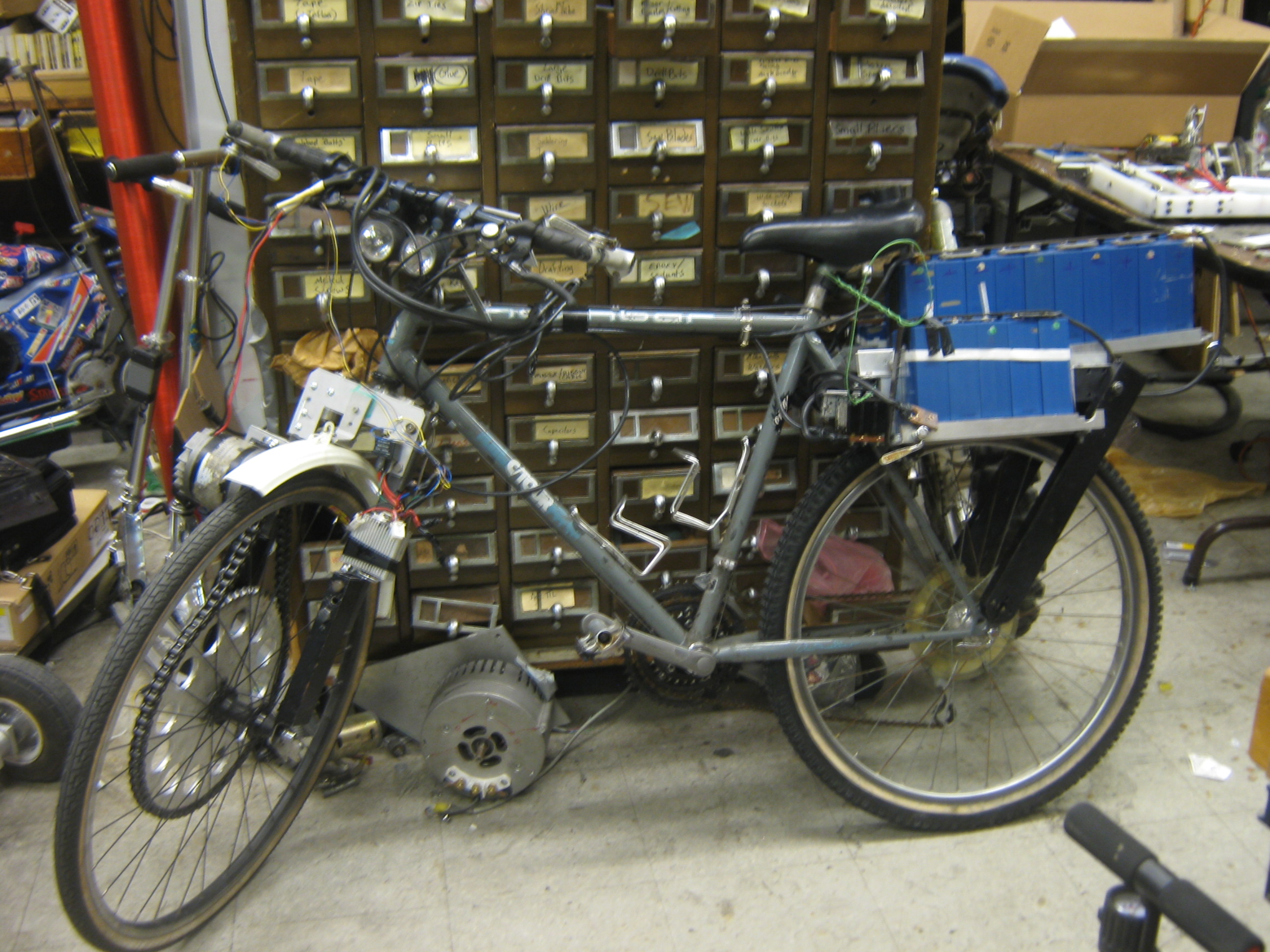
Quick background on e-bikes and project plottingElectric Bikes arent new. DIY folks have been at this since 1895: [First Electric Bicycle]. What I wanted was something that could travel a moderate distance (30-40 miles), and have 'safe' failure modes. If a motorcycle drive train fails, you can't pedal it home. This is the same with most mopeds. With an electric bicycle, you can. You can not only pedal it back, but in a motor failure case, it would be great if you could remove the massive batteries, hide them somewhere, cycle home, pick up the pack later on. Moreover, while your cycling, you're not driving a motor constantly, you are only propelling the vehicle. Way less mechanical drag = better ease of use, less wear. Extra motivationCambridge Mass (MIT) is an exciting place on weekends, Manchester... not so much. This project started off so that I can get there without burning 20 USD in fuel every time I visit. It's an hours drive and traffic sucks in Boston / Cambridge, not to mention that people there are insane drivers TLDR, there's nerdy folks @ MIT to rock out with. The route shows a 16hr "walk" and at the time, cycling directions were not available. 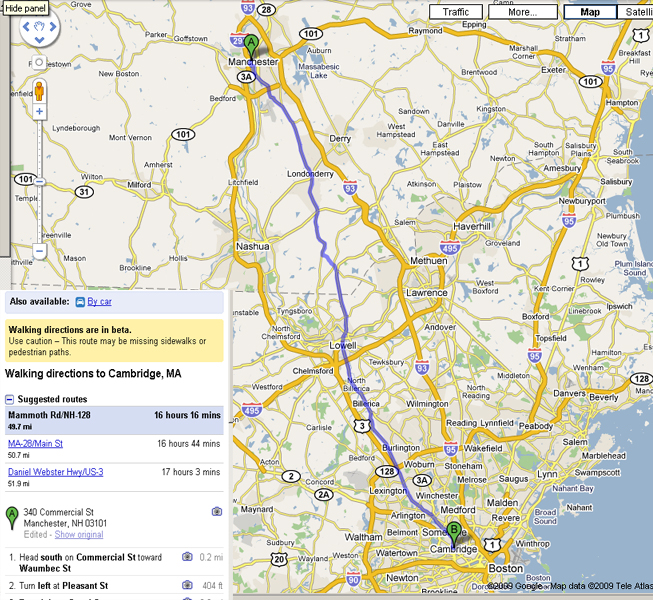
The plot was to go for a front wheel electric drive and rear wheel mechanical drive. This somewhat simplifies the mechanical design as you do not end up with the pedals driving a motor. Using a freewheel, or one-way bearing on the front wheel mechanically decouples human propulsion from electric propulsion. 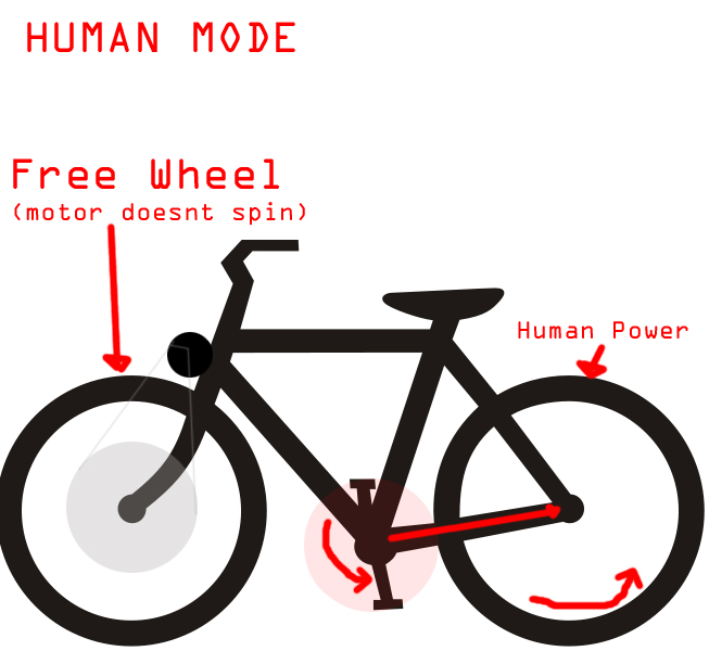
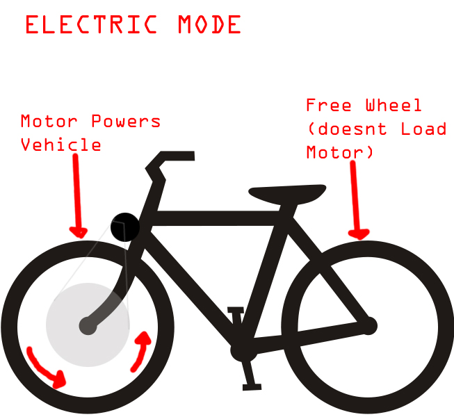
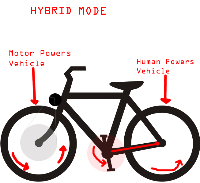
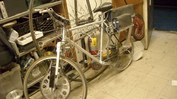
Mode 1, its a normal bike with a lot of extra mass, the motor and drive train for the electric side are completley isolated from each other, and pedaling isnt loaded by the motor, it actually doesnt move the chain at all (thus the 2 free wheels). Mode 2, the system is a purely electric bike, it has a fixed gear ratio, and is front wheel drive, when the motor is over driven (bike is going faster than motor, like in a long down hill, the motor isnt forced by the wheel, its in a freewheel state. also the pedals arent forced to spin up when the motor is on, they are also in a free wheel state Mode 3, the system is a parallel hybrid, wherein rear wheel propulsion is provided by the human, and front wheel propulsion is provided by a motor. This instance would happen when the cycle is started up from a complete stop, like after a red light. This topology, is fairly novel. At the time of building this, front wheel hub motors, or bicycle hub motors in general did not exist, or if they did exist they were not commercially available. While a hub motor became a budget ubitquous item in the late 2010's, they were fairly hard to manufacture on the DIY front. Collecting the partsA host bicycleI Craigslisted a bike, 25 dollars. Took 2 weeks to find a cheap bike, but it was worth the wait (not a pic of the actual bike but rather close). It had some questionable tires but it did work. Fortunatley MITERS had a bicycle graveyard of parts. The host frame being simple actually was a benefit, there was no suspension, so if I was going to use the frame for a motor mount, I would not have to compensate for changing geometry. 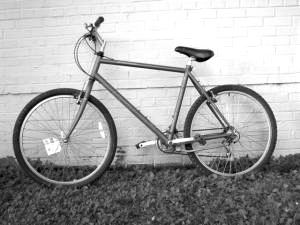
The BatteriesThis is key, batteries are the achilllies heel of any project. I managed to get NiZn recycled forklift batteries via a friend (John Mcmaster, you rock). Yes, NiZn, I had no idea they existed in this format either. Check your local recycling center, or just ask around Craigslist. I scavenged somewhere near 36V at 85AH, or nearly 3kwh of energy storage. The total mass is less than 45lbs. I brought these back to the RPI electronics club and idiotically charged them in a weird series parallel arrangement using banana clips. Realistically i should have put all of these in parallel groups and let them sit for ages at 1.6V until they top balanced with each other. 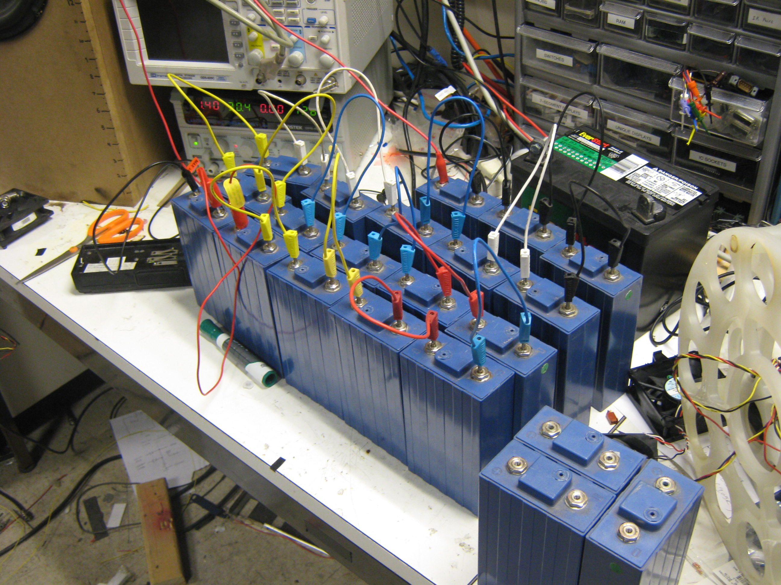
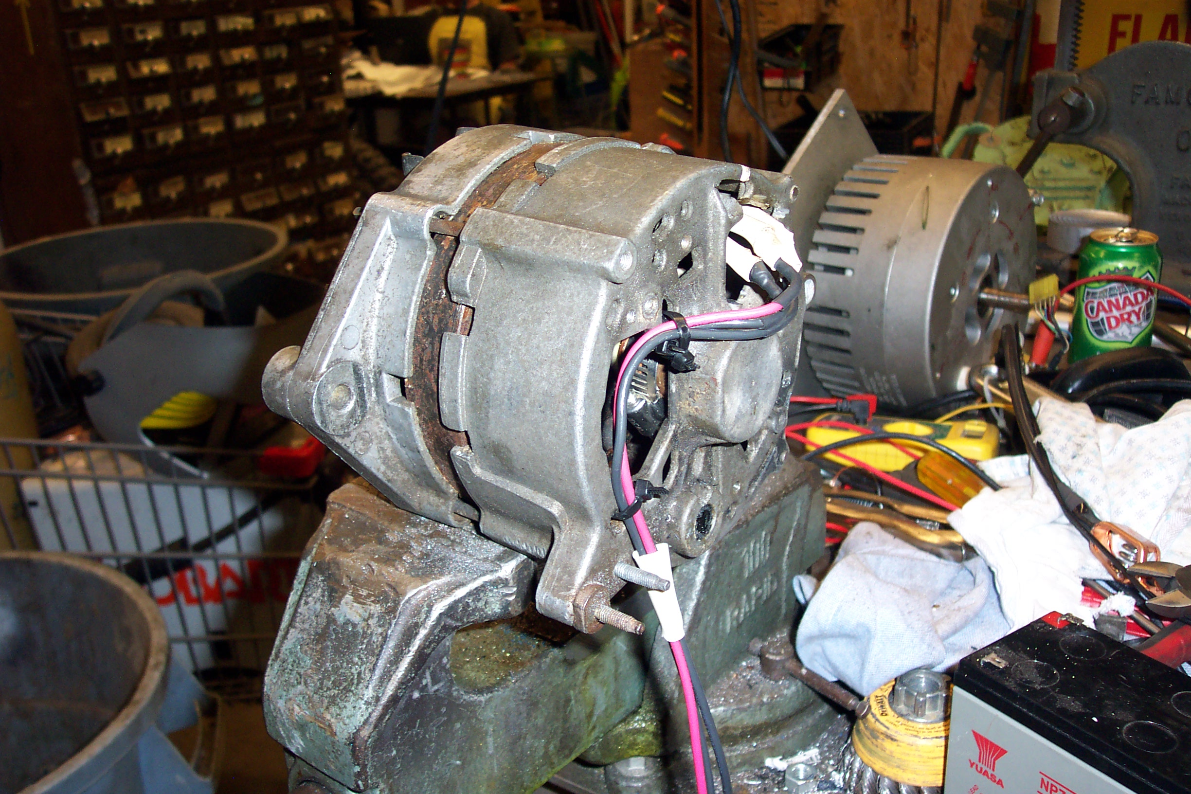
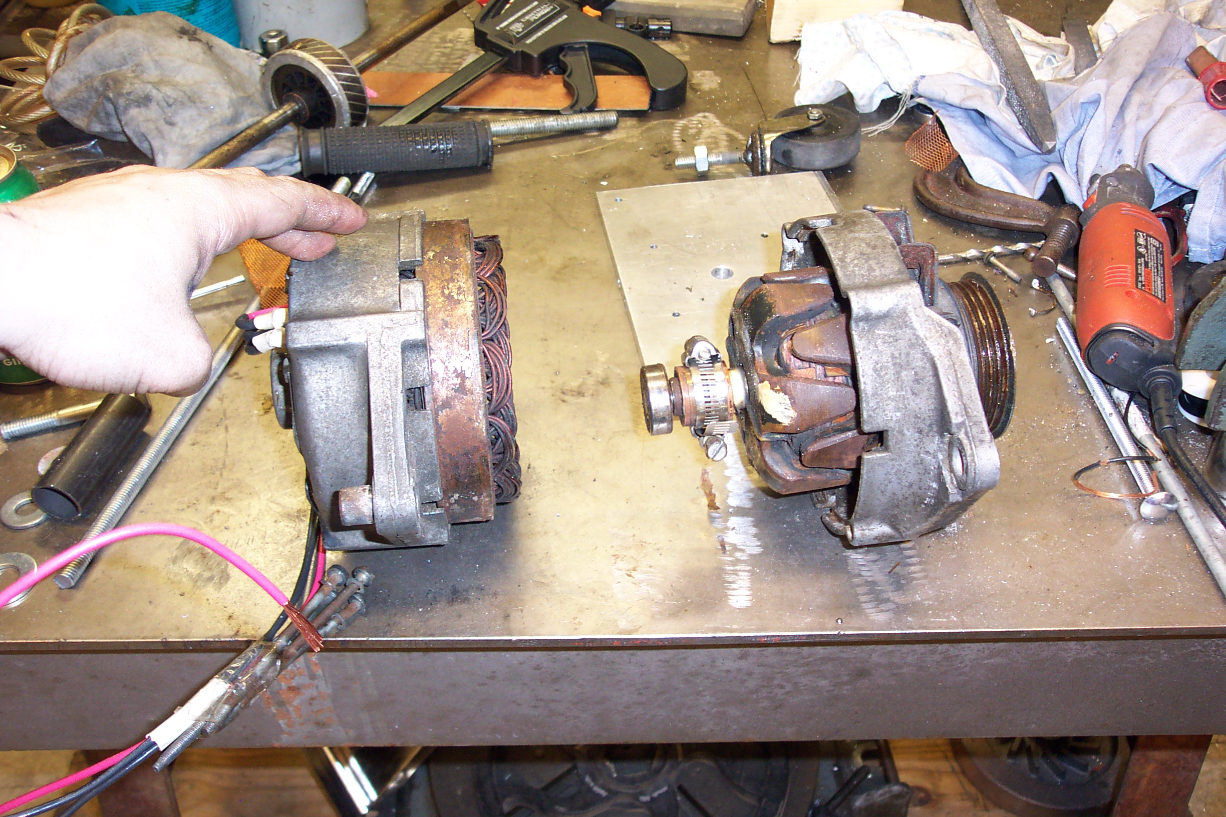
A MotorMy plan was to use a defunct alternator as a motor. This was a loading-dock find and lacked brushes for field winding, then again, I didnt really mind, as I wasn't planning on using them. The plot was to make a PM mag rotor and drive the stator windings using a homemade three phase motor controller. Re-using this motor was signing up for quite a challenge, but it promised to be possible to extract at least 700W if the rotor-gap was small enough. 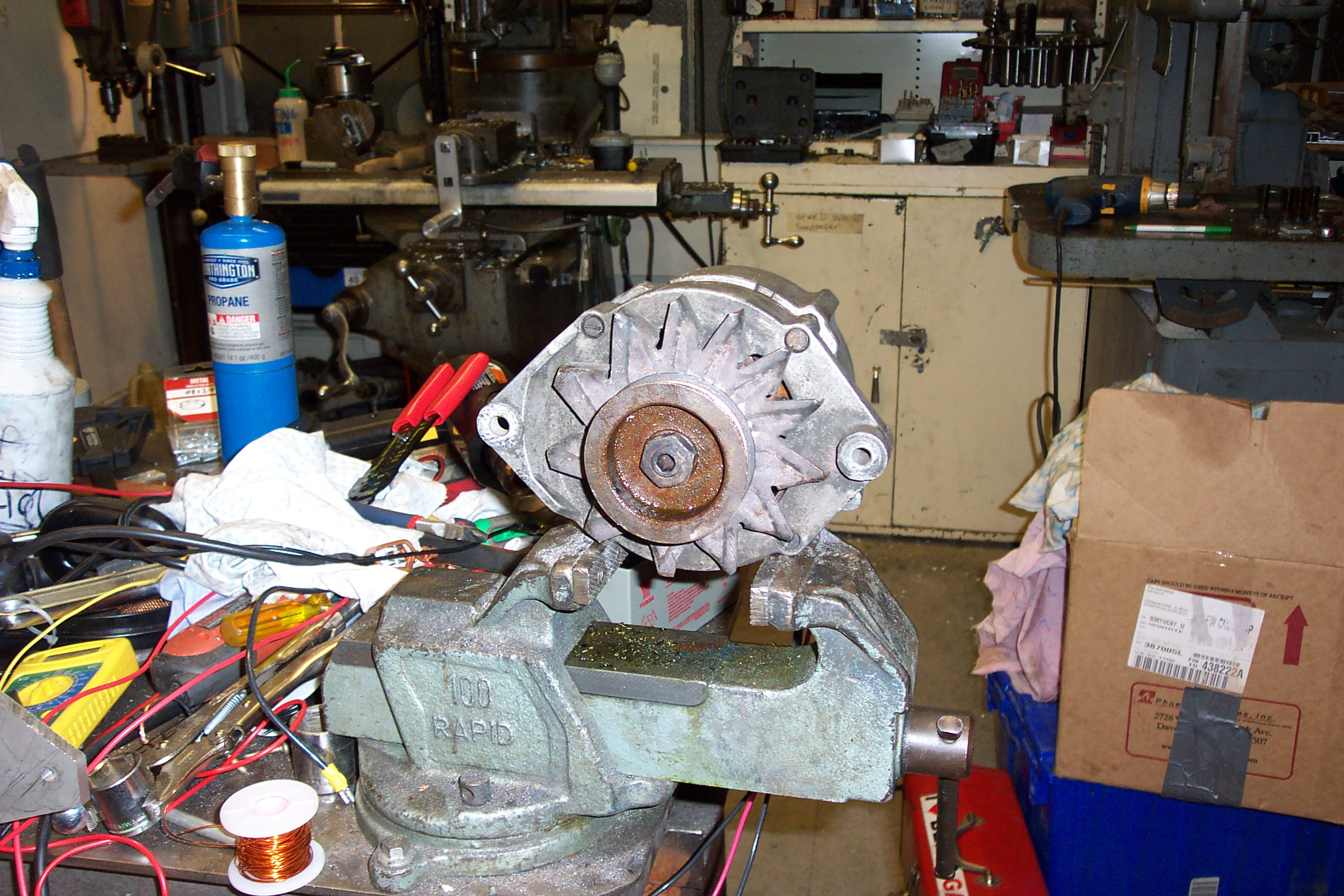
A DrivetrainPart of this project also started because this comically large FSAE sprocket appeared. This was thrown out from MIT FSAE and just begged to be re-used for something. For a bicycle it is so comically over rated. It's so large that it is funny and makes it's use on a bicycle even more absurd. This sprocket inspired my first mcmaster-carr purchase. [A tiny 9 tooth sprocket] and [A comical #50 size chain] 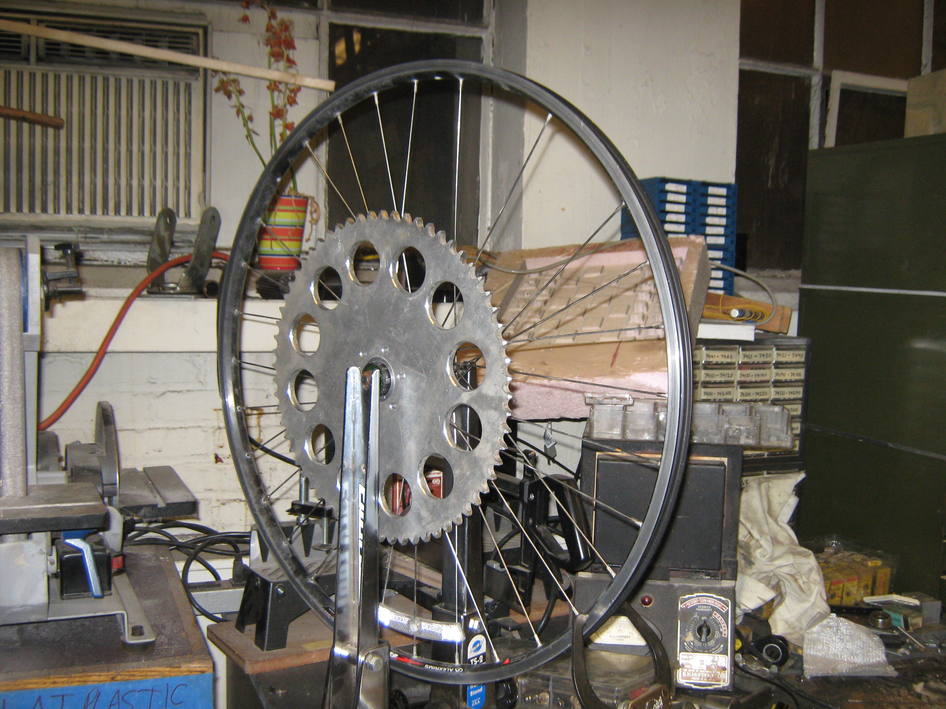
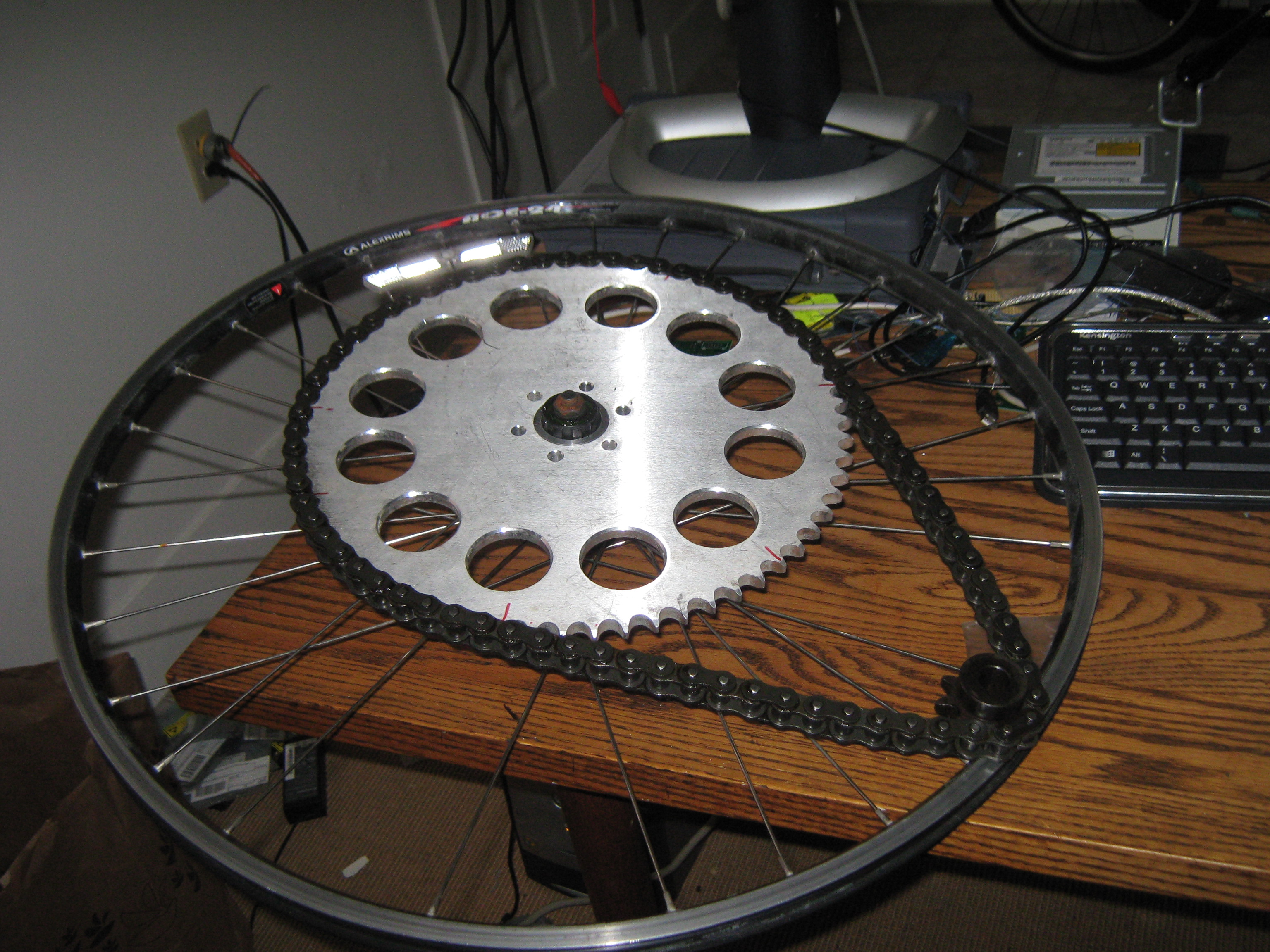
The Build ProcessThe main sprocket was free, courtesy of MIT FSAE getting rid of it. as you can imagine, its overkill. However free is free, so i designed with it. After basking in the glory of this sprocket, I fabricated an adapter for mating the gear to the 'free wheeling' part of the bike tire. This is actually a rear casette wheel assembly being used on the front fork. Normally a rear wheel is too wide for a front wheel assembly and this is resolved by building larger forks. With the wheel assembly on a bike stand it becomes pretty apparent that any normal front forks would collide with this enormous sprocket. 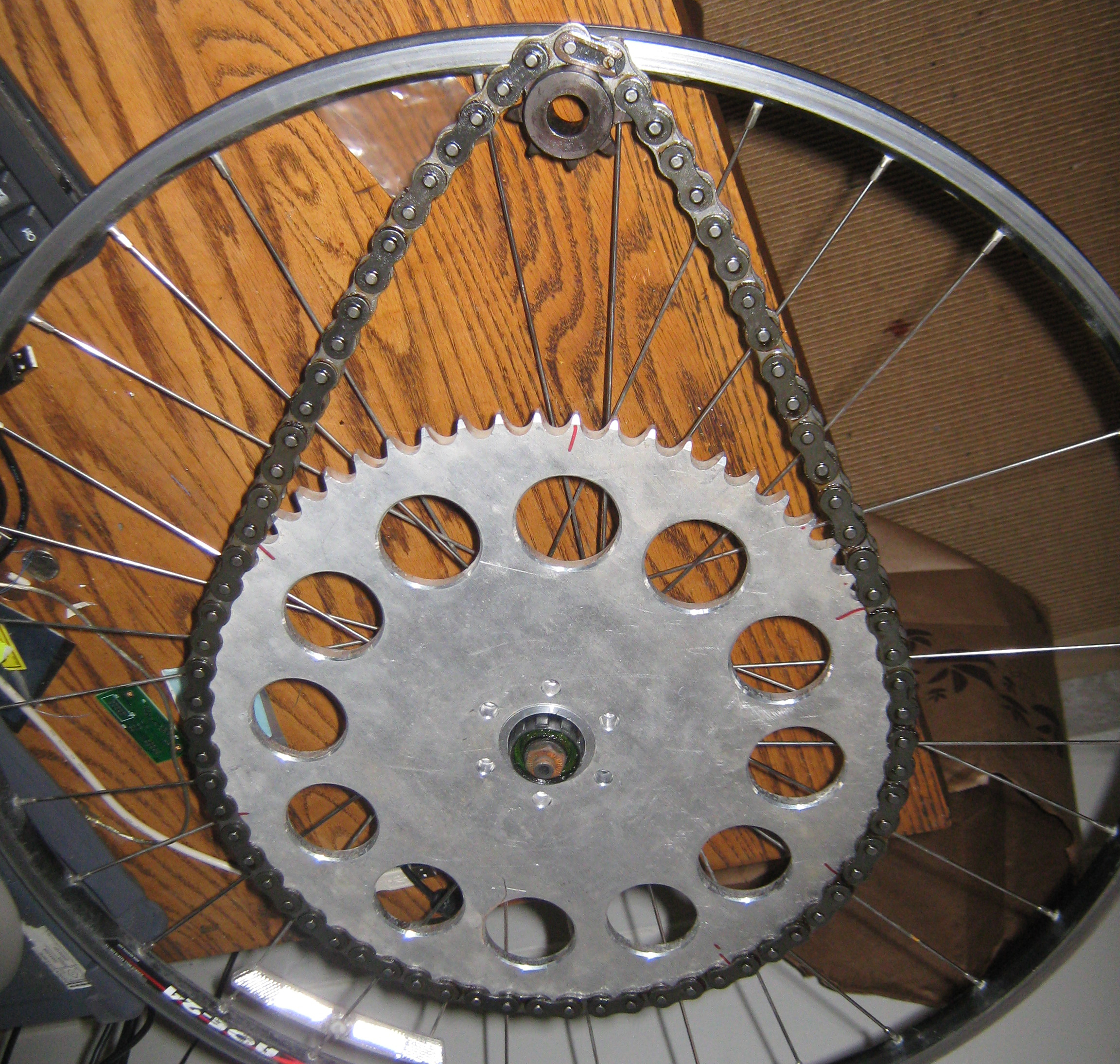
It was necessary to increase the width of the front tire gap by a whole 1.48 inches to clear the sprocket. The goal here is to only use surplus / scrap material for budgetary "im an intern" constraints. Making the front forks ended up becoming a mix of 1" square steel tube mated to rectangular aluminum extrusion. It's mechanically not great, but a reasonable first prototype. The 1" square tubing fits over the existing front wheel tubing, while the larger extrusion has enough space to add in a quick release mechanism for the front wheel. I did not have accessable welding at the time, so this was mostly assembled with a pile of miscelaneous bolts. 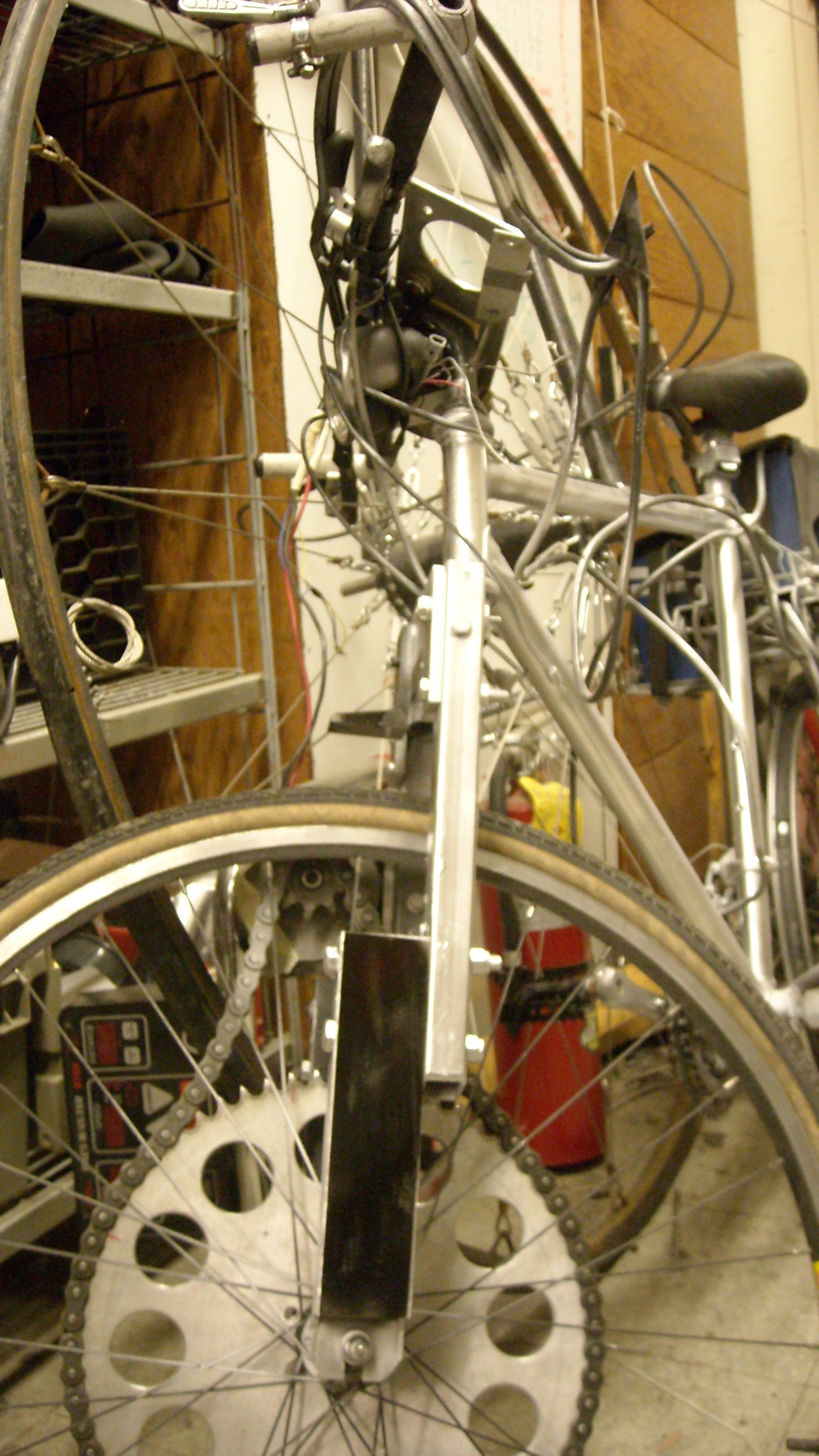
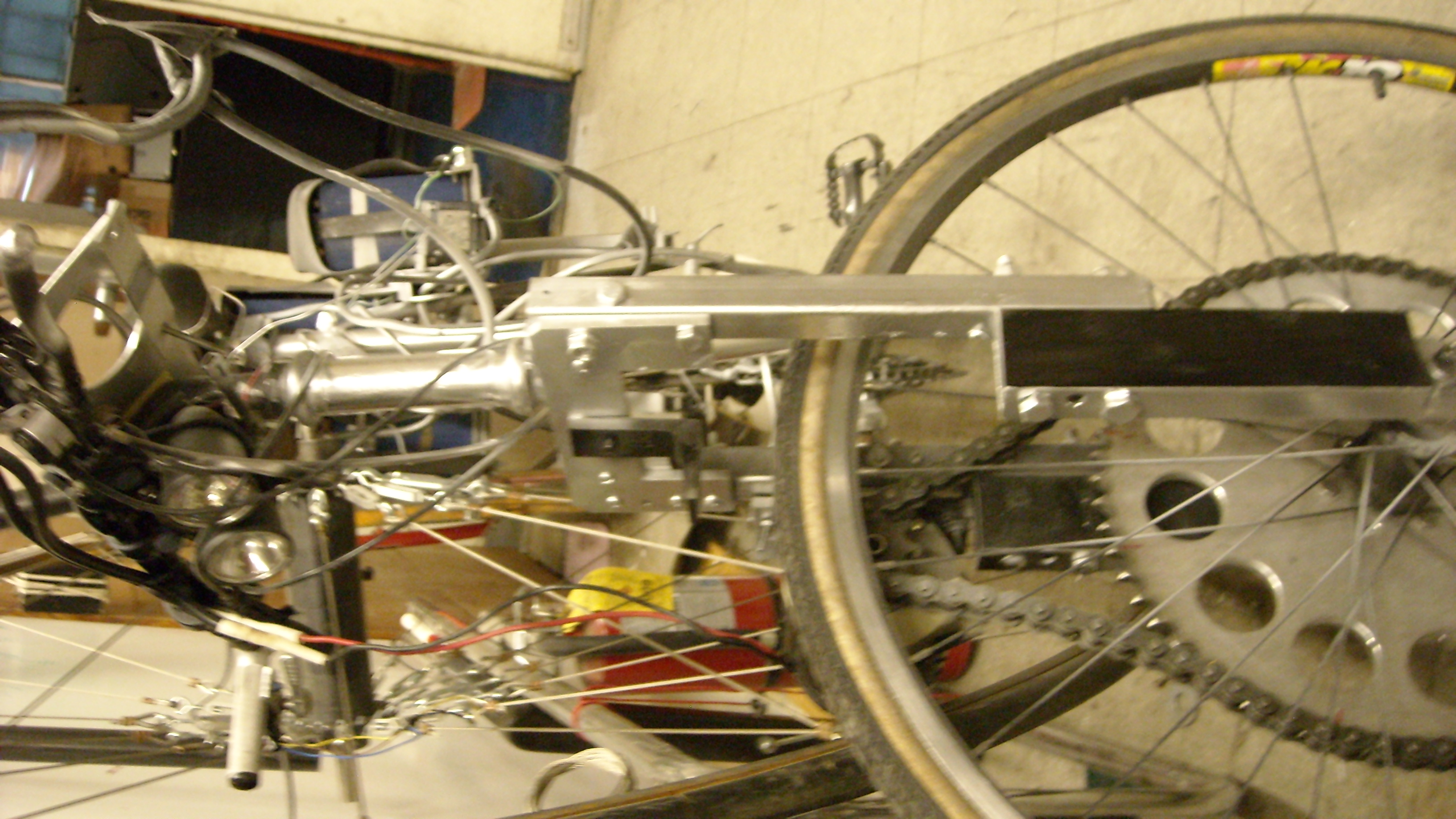
A somewhat better view of this 'assembly' is visible below. 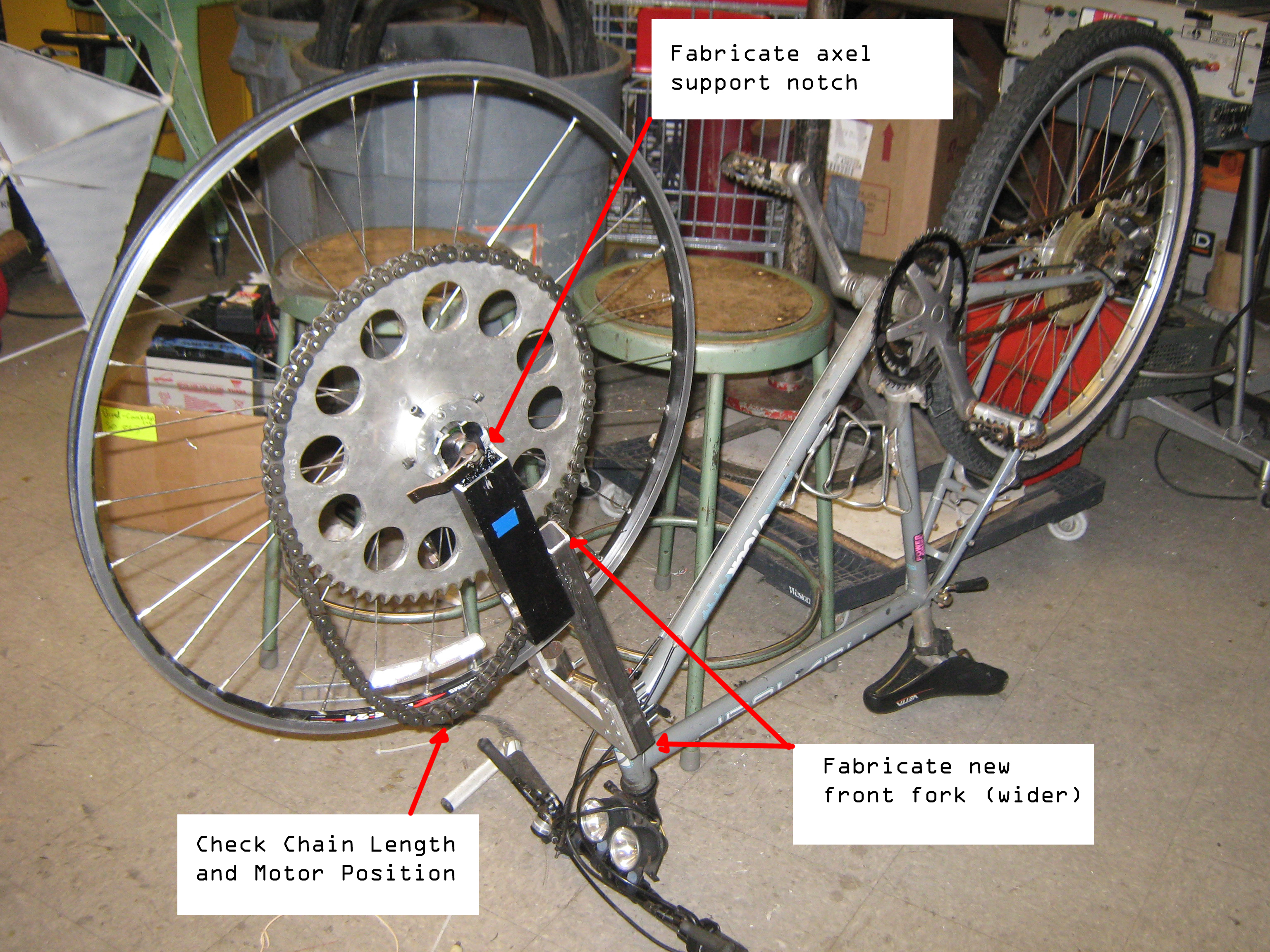
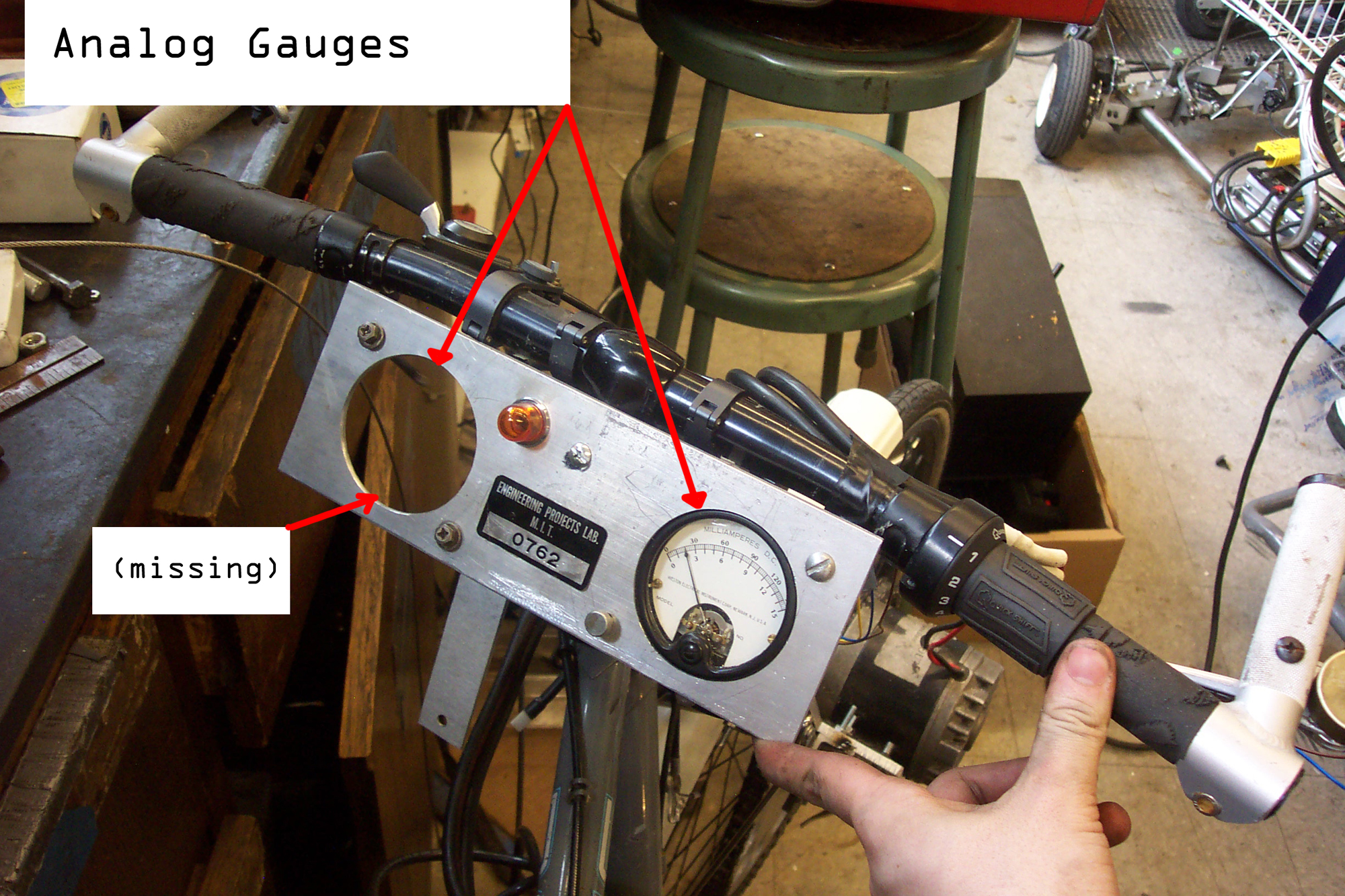
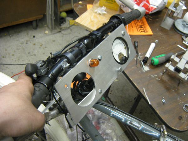
For the user interface I milled out 2 holes for semi-recessed analog gauges. The gauges would be used to display anything from volts to distance remaining. I chose gauges because the bike was supposed to have a somewhat old-timey theme. Initially I found one of the gauges from MITERS and eventiually found a seond one at the MIT Swapfest. These turned out to be miliampere gauges so it was necessary to use a network of resistors to convert the battery pack voltage down to a 0-150mA signal. Because this has a resistance the gauge would discharge the battery pack if the battery was left connected. The second gauge was used to display motor current by directly reading a shunt. Comically I found out why analog panel meters are not installed on vibrating bouncy motor vehicles. The needles on the gauges bounce all over the place and after a long ride the 'zero' setpoint is no longer zero. Finally the sharp corners on this 'display' were a bit of a mistake, they ended up getting rounded to prevent getting gouged in an accident. 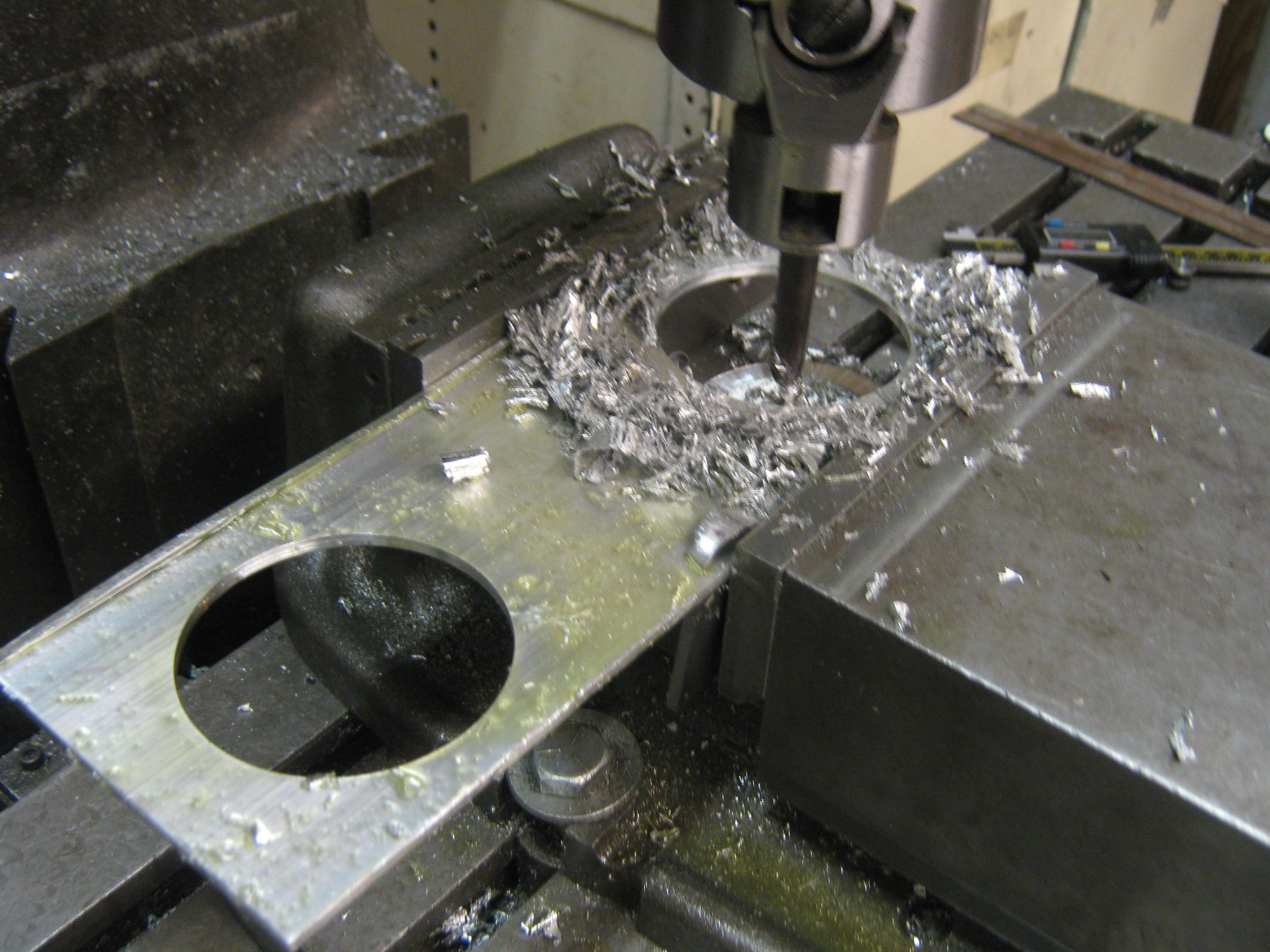
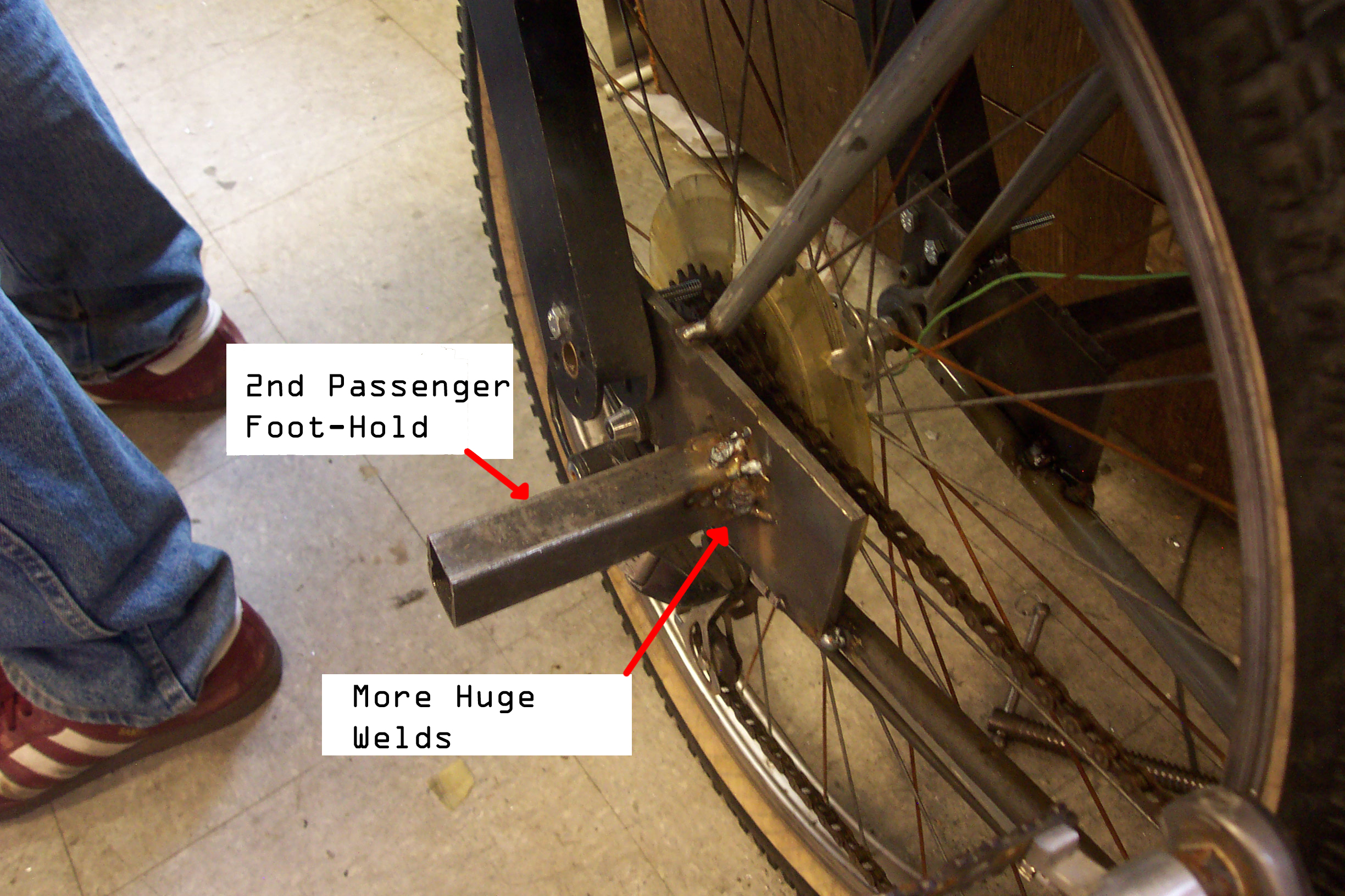
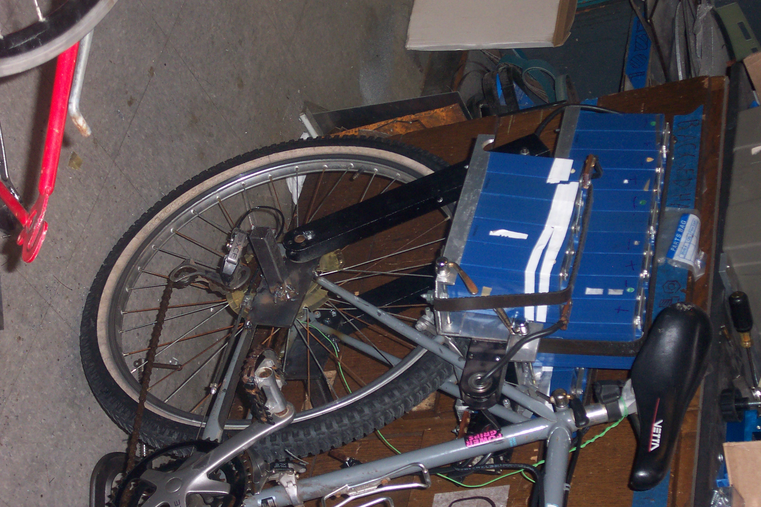
To increase the carrying capacity of the rear portion of the cycle, steel plates were added to either side. I mistakenly labeled these "iron" in the attached photo. These were used to add a rear mounting spot for the battery rack. At the time MITERS had a very basic MIG welder hidden in a corner which was only used intermittently. My MIG welding experience was incredibly limited. The plates were cut out to allow for the rear wheel quick release to still function. Finally 5" long steel square tubing was welded on as a second passenger foot rest on both sides. My word these welds were dubious. 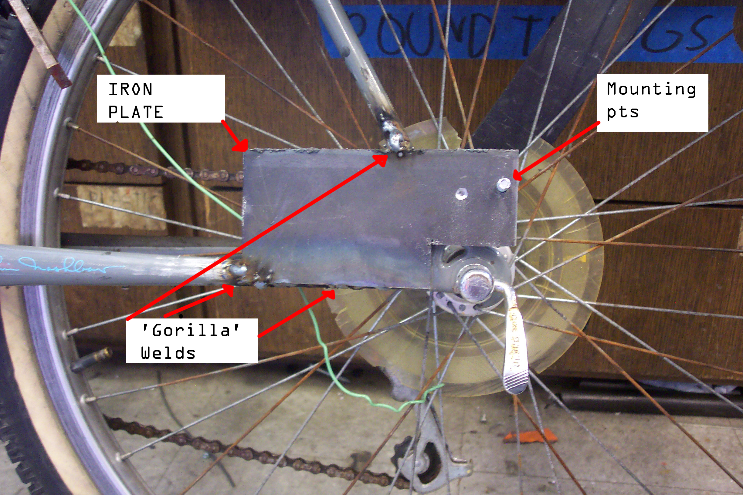
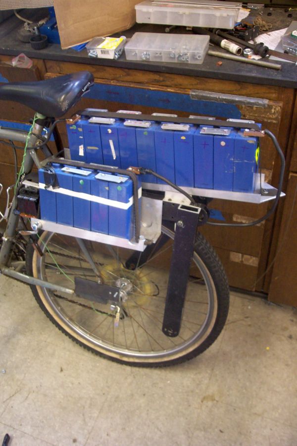
Battery RackSorting out the battery rack was a bit of a challenge. Bicycles can have a rear pannier but not something this enormous. The battery modules themselves were attached to aluminum u-channel, and that u-channel sat in a slightly larger u-channel. To keep the batteries in place i used old serpentine automotive belt to keep the cells in place. The pack was split up into three sub modules, one with 10 cells in series and two with 5 series cells a piece. NiZn cells are 1.85V max and ~1.6v nominal. A fully charged pack is ~38V and around 32V average. 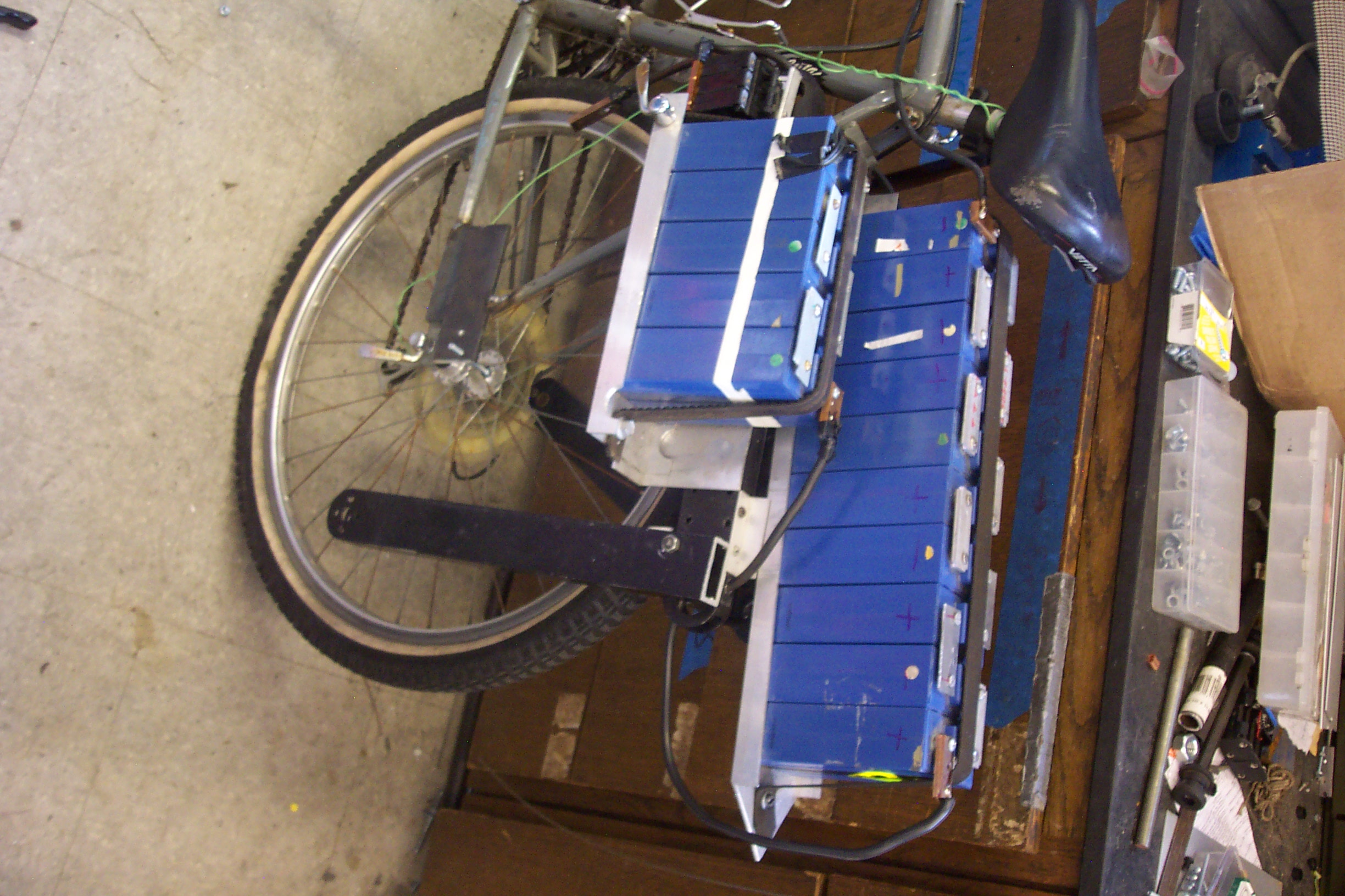
I did not know better at the time and instead of wire lugs and flexible jumpers I used plates of aluminum. This really is not a great idea as this overconstrains the cells and can add stress to the electrical connections. 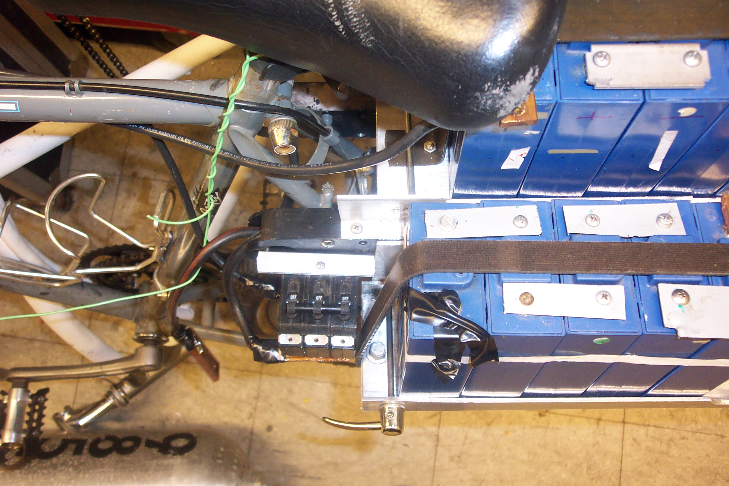
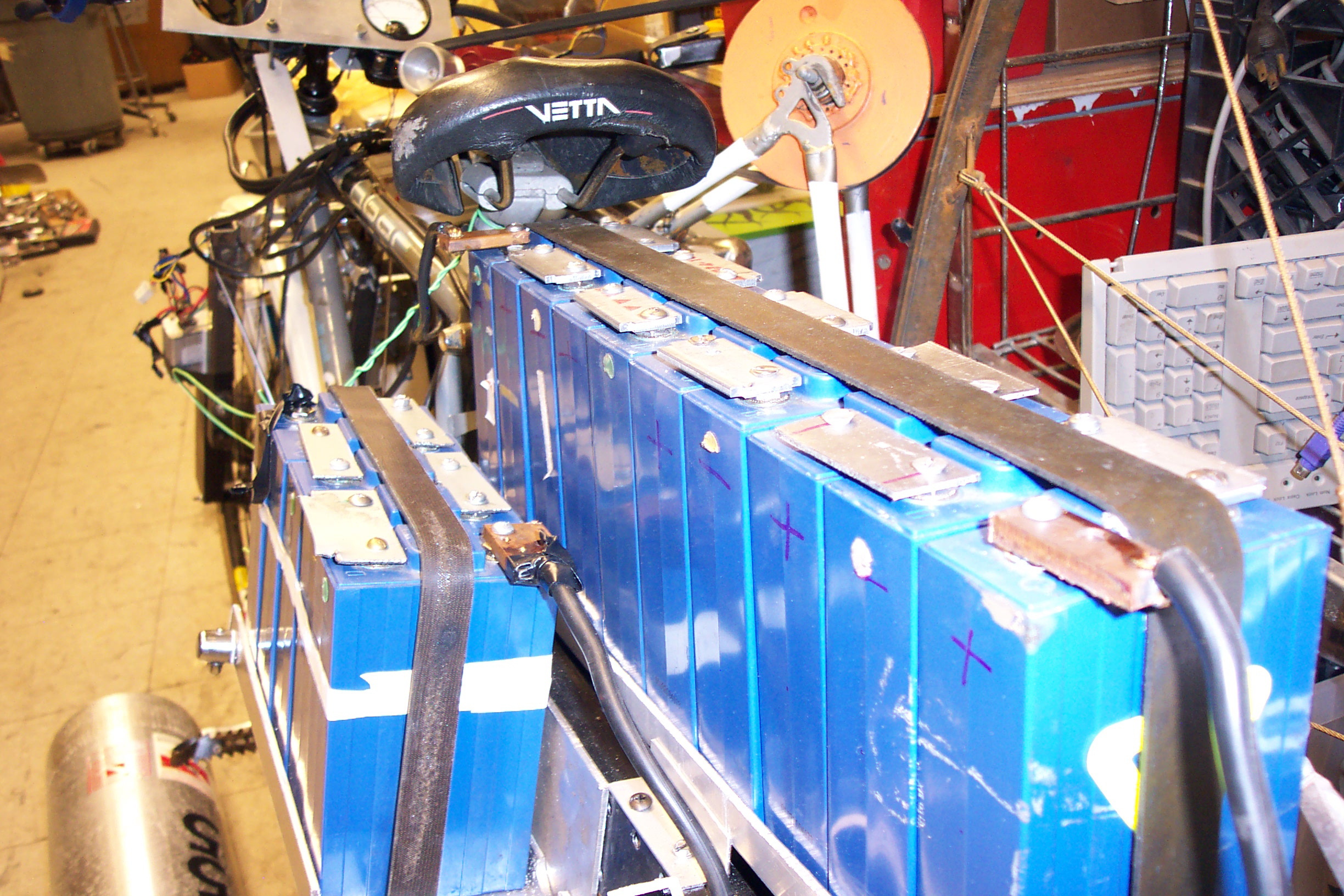
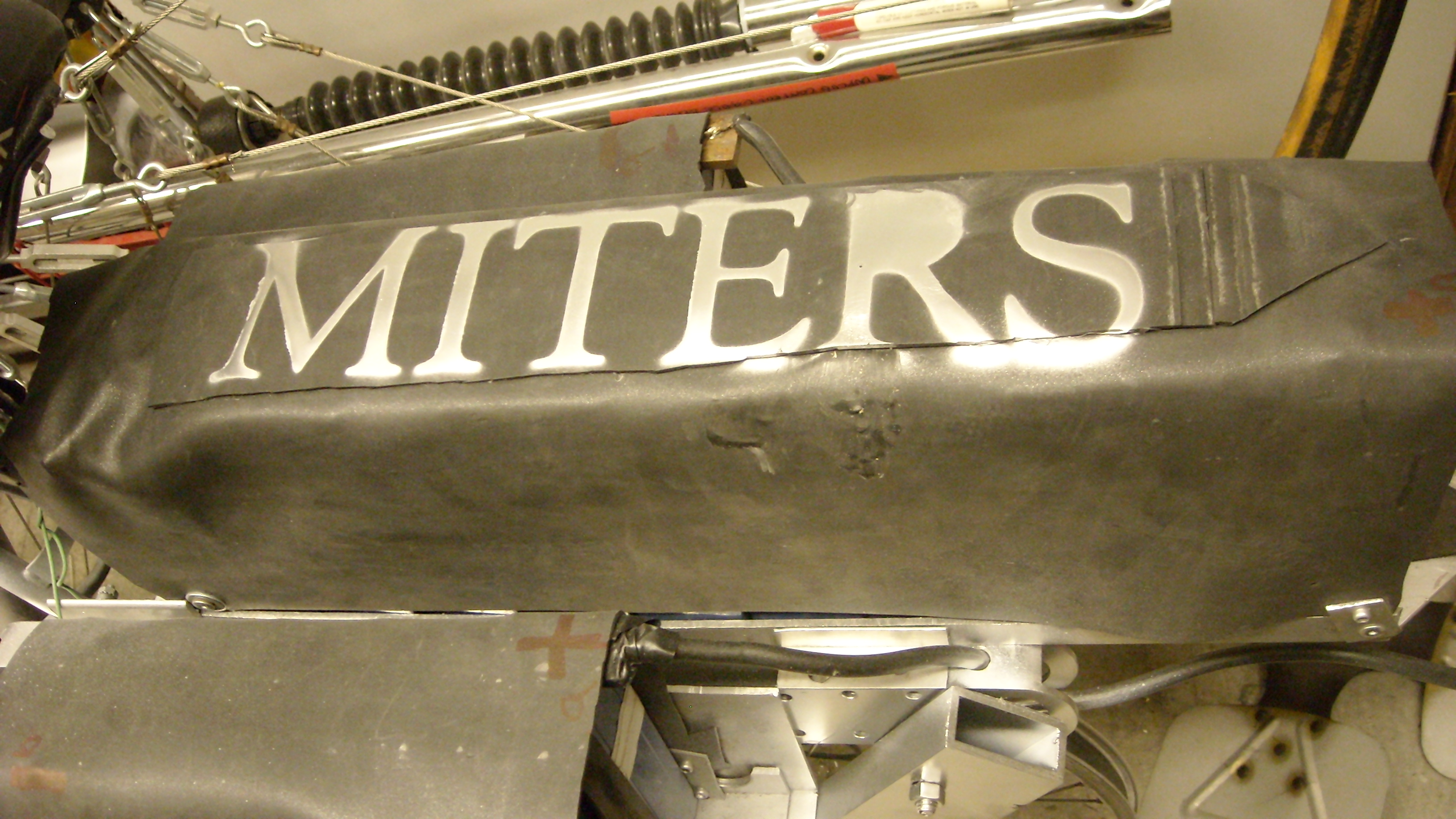
The batteries become a seat for a second rider. To help prevent the operator from getting warm or being part of the current path i found some 1/8" thick rubberized sheet. These wrap around the packs and keep the terminals from getting exposed to the elements. I used some vinyl sticker to generate the stencil for spray painting on a "MITERS" logo. 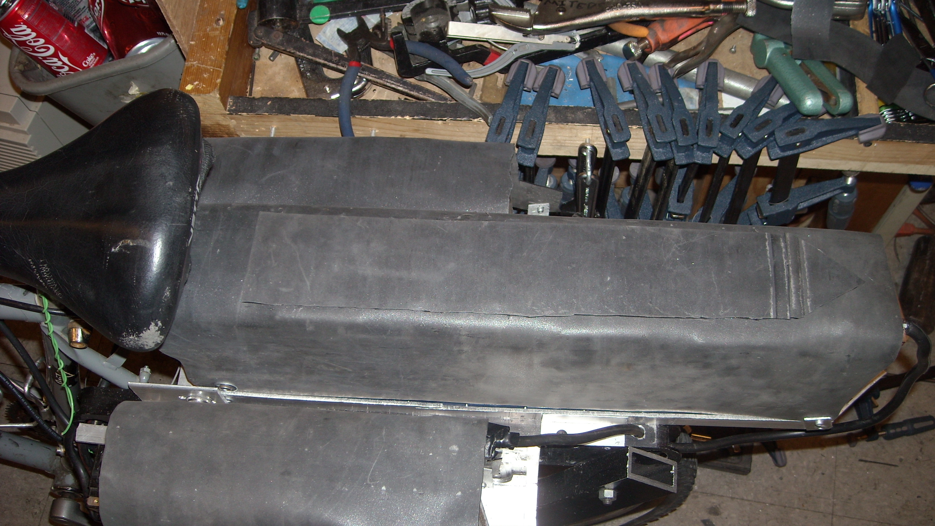
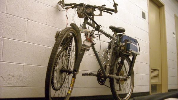
The view fron behind was pretty interesting. This vehicle was so much fun to work on as it was just a constant experiment. 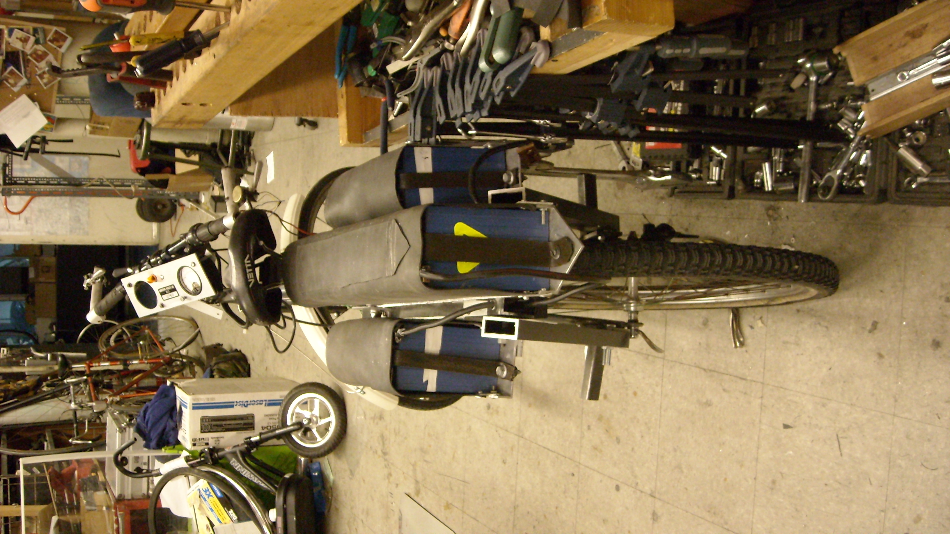
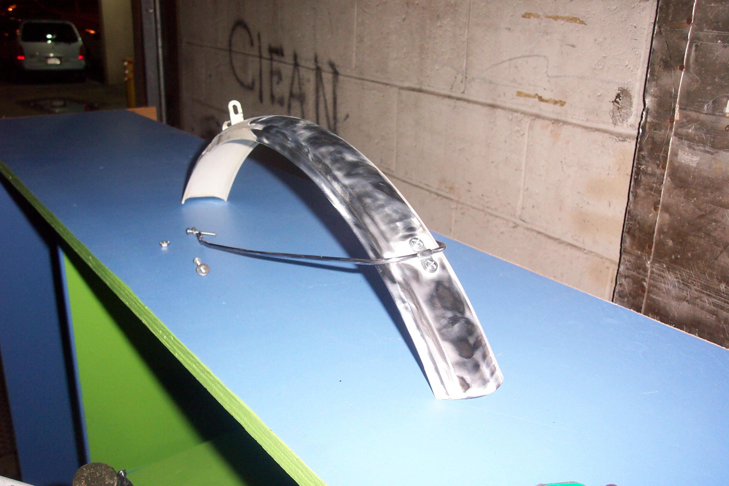
There were a few things that needed to be tidyed up before riding with a second person, the first of which was a front fender to keep street-water splashes to a minimum. I found a somewhat derilict front fender and opted to strip it down with a wirewheel and paint it chrome with some dubious spraypaint. I was also hoping the fender would catch any chain that would likely rocket off when it finally decded to rocket off into space. 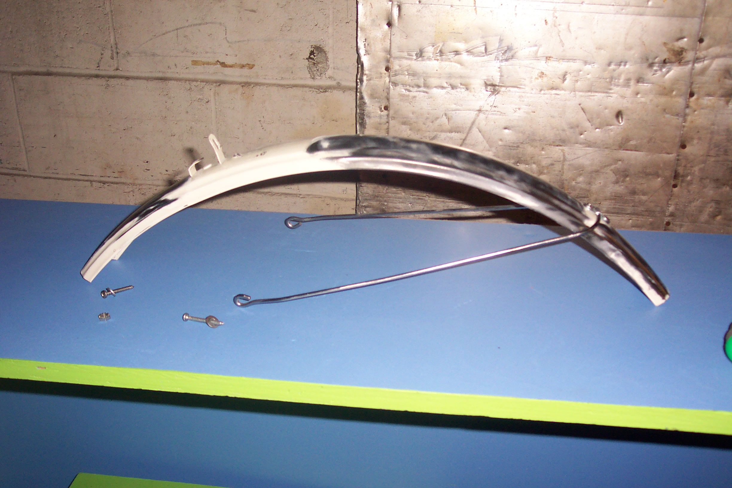
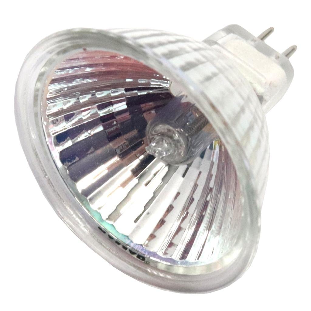
Early testingWith this first setup I ran a test outdoors. While I had found a DC Brush motor controller this particular test was a simple 30A circuit breaker as an on-off switch. This was not, in any way, controllable so instead I would cycle up to speed then enable the circuit breaker to coast around. One of the first things that's visible below is how fast the wheel is spinning and how loose the chain appears. Front Wheel Spool Up Outdoors, with audioAfter some chain tensioning and fiddling it was time for a first test run. This is still 'circuit breaker drive' and at the time I had not added in onboard lights which was somewhat dangerous. Shown below I cycled up to approximatley 10mph before enabling the circuit breaker to add propulsion. At this point Miters Steve decided to go for it and see if he could catch me. First test with contactor drive, with audioLet's add some lights36 volts is an odd one for lights. I found a dual headlight mount from an abandoned bike but it was without bulbs. The MIT museum fortunatley recycled a pile of 12V MR16 painting highlight bulbs. These bulbs were not LED, so they ran hot, but were fortunatley incredibly bright. As these were nominally resistive lights, i was able to run the two in series right off the main battery pack rail. They ran hot but were quite good for evening expeditions. I ended up having to hunt down fixtures at homedepot to mate the bulbs with which was kind of silly. The lights were effective and visible in the video clip below. 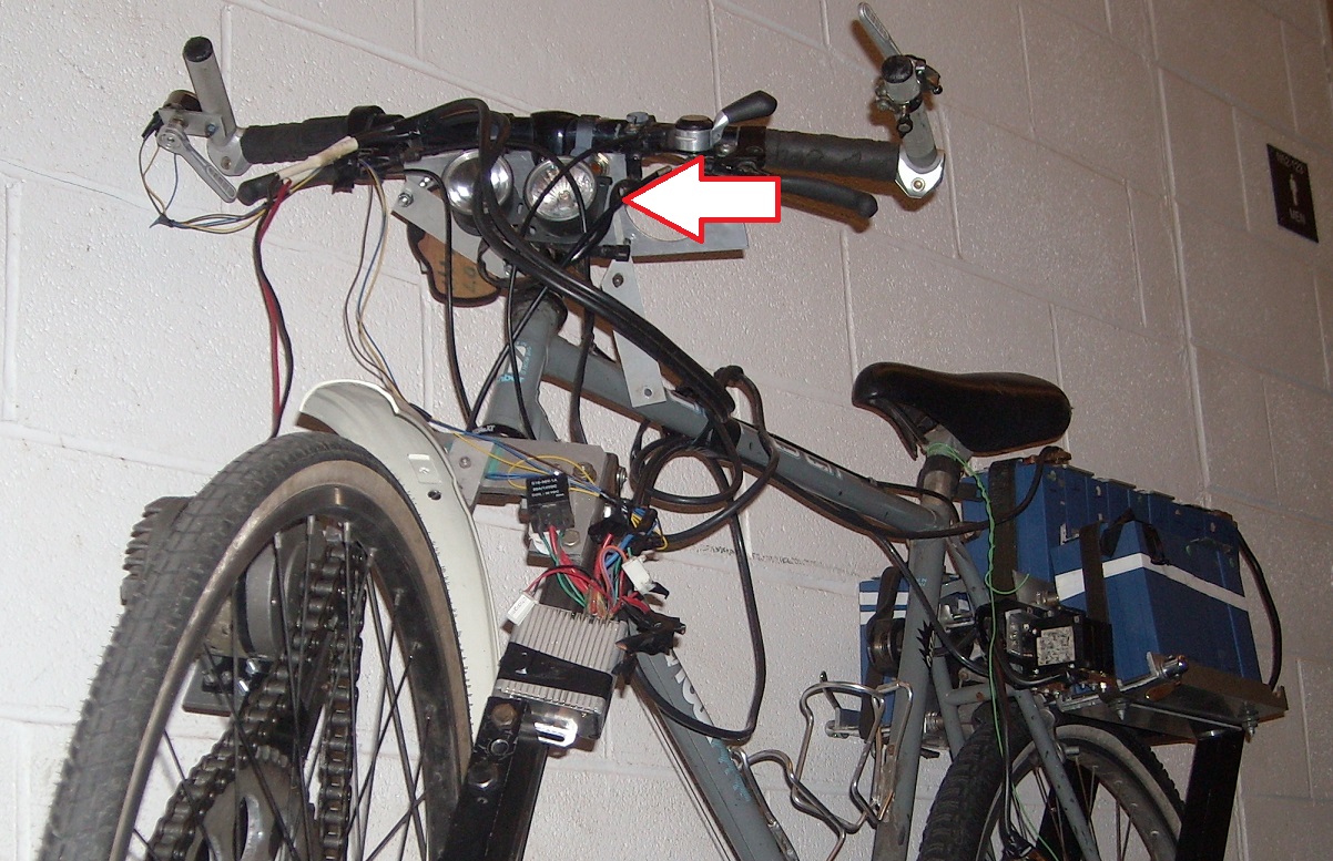
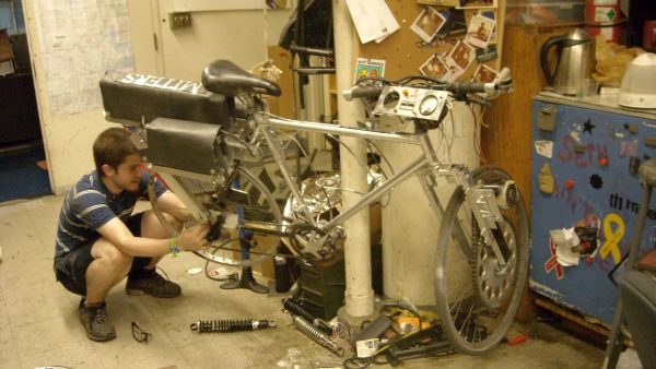
Solo riding, with audioTesting with two passengersThe rear battery rack is structrual enough for a second passenger to climb on. I ended up adding foot pegs for the second rider at a later date but it was great to find out that this was workable. This test was with the first generation 'temporary' DC brush motor, and even though it was functional, it was fairly power constrained. It was able to keep pace at 20mph but at launch it struggled. As a result pedaling to cruise speed was necessary. You can see at the end of the video how it was able to maintain pace at 20mph. Also, my goodness low light video is so terrible from this era. I think this was recorded on a cannon powershot point and shoot with a pea-sized sensor, in 4:3 ratio. Two passengers zooming around, with audioUpgrading to threephase:The next step is to upgrade from dubious 'circuit breaker' control to having sensorless three phase propulsion. This involves converting the rotor of an automotive alternator into being a rotary magnet assembly. This was not straightforward, so I tried to constrain the project to getting the motor to spin up, characterizing it, and then figuring out how to adapt it to the existing frame. 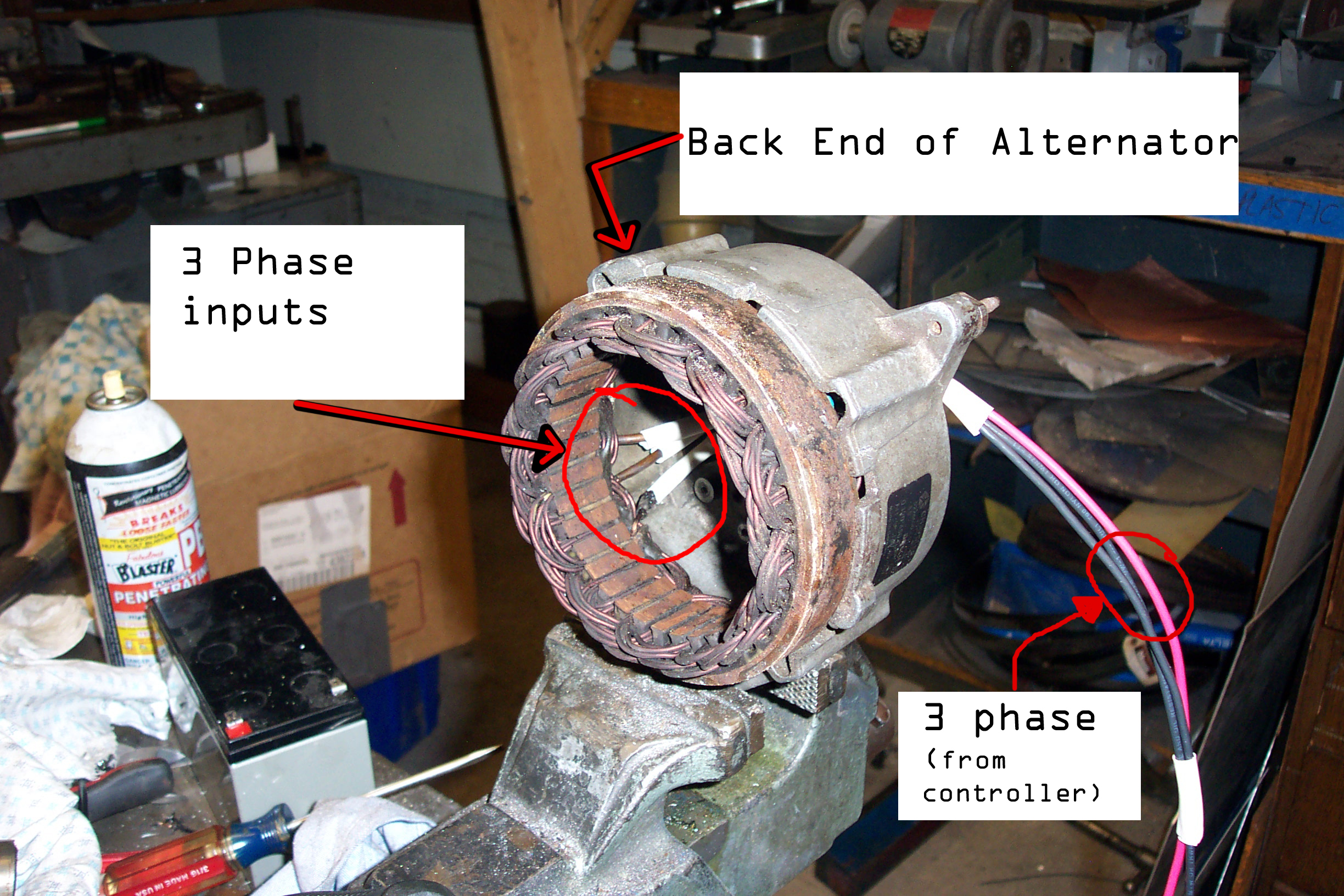
Concluding Remarks:The test run between Manchester NH and Cambridge MA was a dubious idea in retrospect but incrediby fun in the moment. I was pulled over by NH state police and they mostly just admired how dorky it was and gave me advice on a safer route. The batteries ran out 2/3 of the way through, as unsurprisingly New Hampshire is very hilly. The ability to jetison the batteries when they were depleted worked remarkably well, re-using bicycle quick releases was great. I ended up just hiding the depleted batteries in some bushes and marking the location on my ancient recycled Garmin GPS. The following day I came back with a vehcile to recover them. Going back and time and updating this page was a curious one. This was one of my earliest large projects and the old format had decayed significantly over a decade. The web changed a lot over this time, mostly for the better. One of the things I struggled with at the time of initial writing was media and storage. I had not quite established a good way of storing pictures, how to structure directories and how to view them. I was using a WYSIWYG editor and image scaling did not quite exist, embedding videos was barely functional and the web was still new. I was also learning on the photography side of things. Half of these photos were taken with A 4 megapixel Kodak DX4900 and the other half a Powershot A470, neither of these are photography powerhouses especially for video. Moving to having storage Unrelated to this project, as I was finishing this bike MARS had finished the final modifications to his tallbike. Quite a wonderful contraption. Mars riding his tall bike from MITERS, with audio
Have you noticed that there are no
advertisements or ridiculous pop ups?
|
Post your comments! |
|
Comment Box loading
|