Dane.Kouttron
[1.2.10] IBM 7575 Arm Development
Update: Check out the 3D-Print-Arm Project that's based on this platform!
| What?
Aquired an IBM 7575 Robotic arm from a lab-cleanout, without controller. Its awesome, but far from operational. The following page documents upgrading motors to high-torque steppers, building controllers and feedback systems in attempts to get the arm controlled by microcontroller. |
 |
| DISASSEMBLY
DOCUMENTATION |
STEPPER MOTOR INSTALL | DRIVER HARDWARE | IMAGE DIRECTORY |
Disassembly Documentation
| Descriptor | Image | |
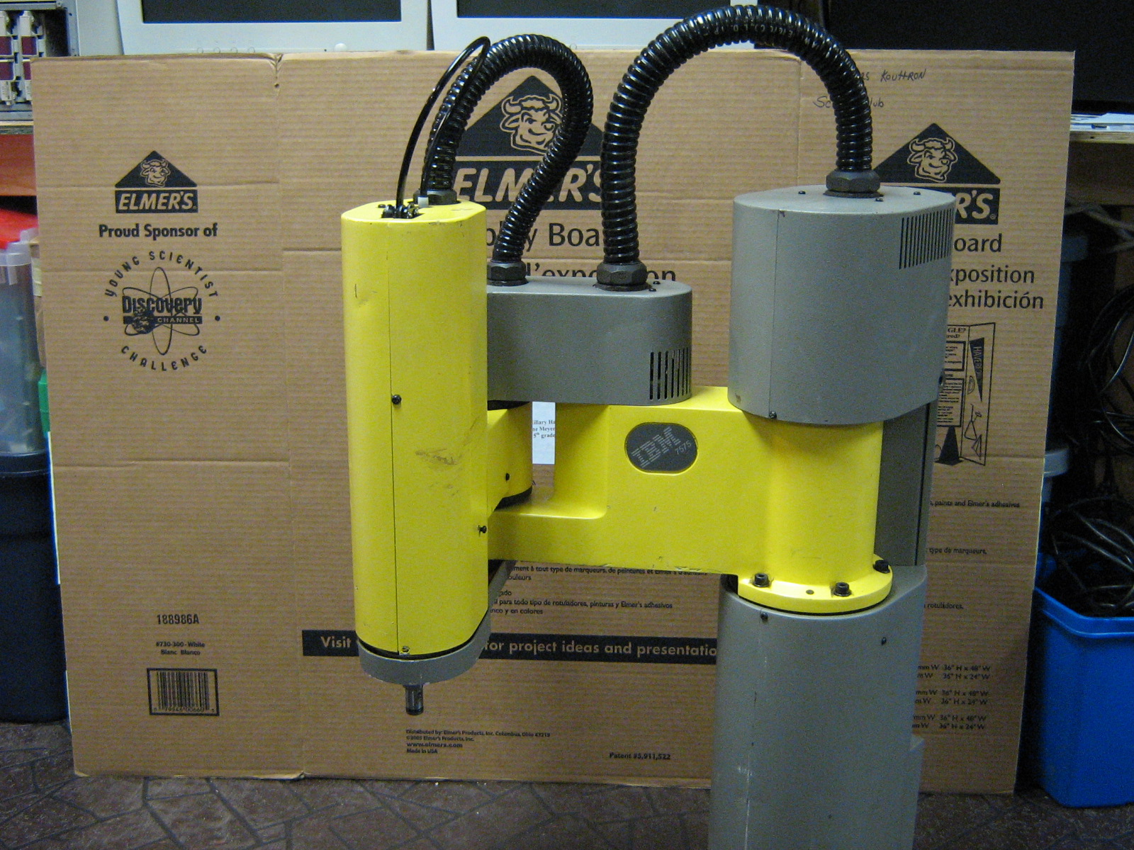
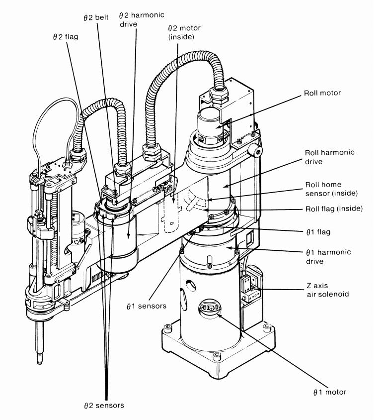
| The
following describes the disassembly and replacement of a DC brush motor
drive, and swap in of a 4 wire stepper motor on an IBM SCARA 7575. Shown left is an image from the begining of the Arm disassembly, the theta 1 motor assembly is visible. Theta 1 is driven from a DC brush + encoderer'd motor and a belt drive, to a 1:3 planetary gearset A sketch of the system is shown right, its an image from IBM 7575 manual excerpt, borrowed from (LINK) |
 |
 |
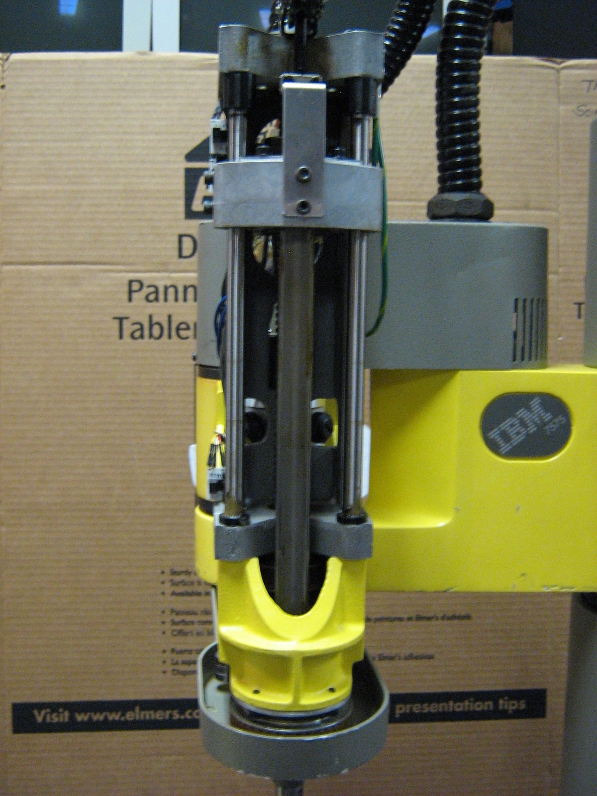
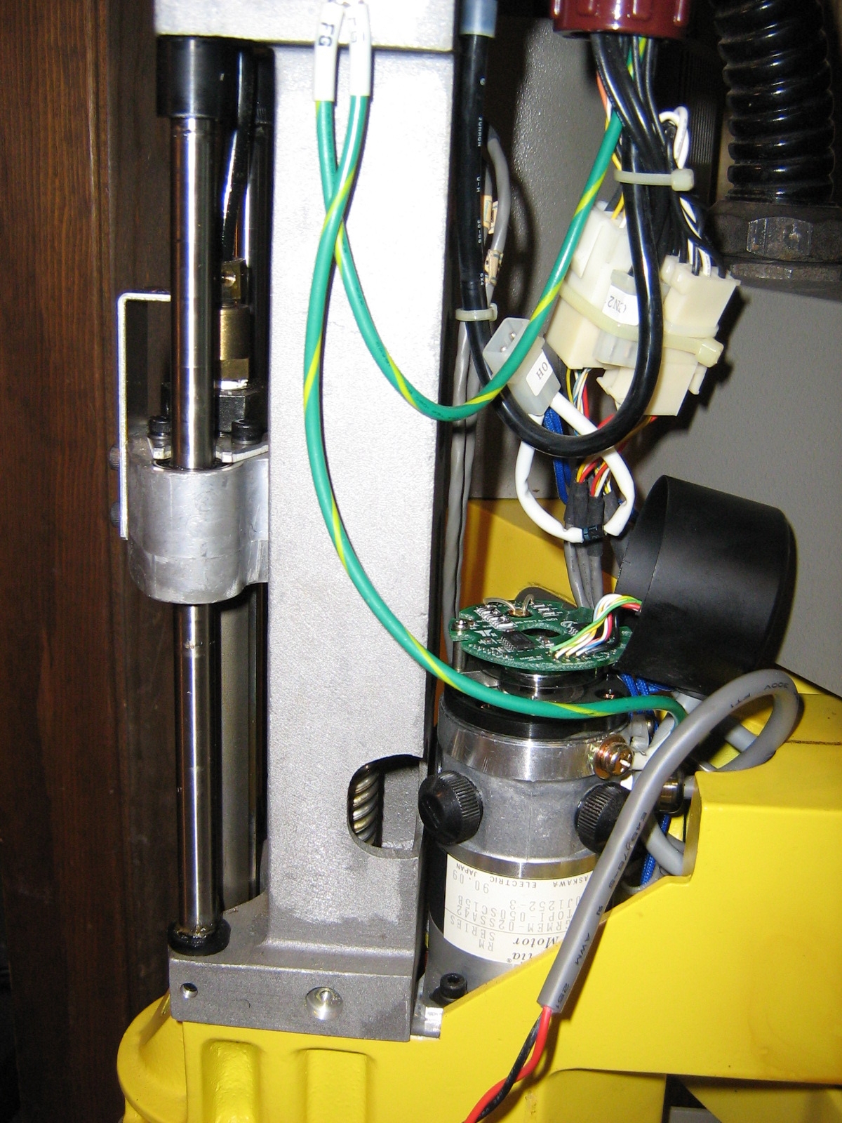
| Front
z axis assembly image. Arm is
driven by Brush DC motor thru wormgear setup. Optical encoder is used
for positioning feedback. IR beambreaks are used for the end of travel sensors |
 |
 |
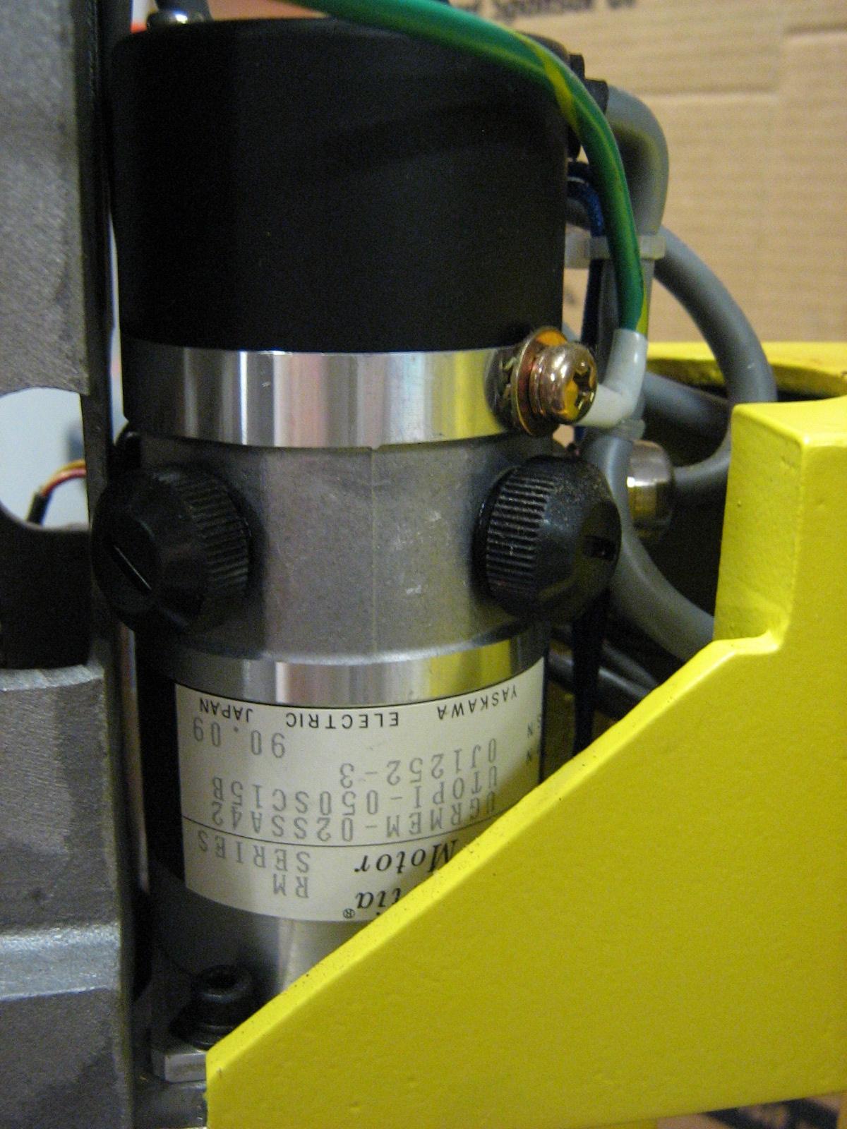
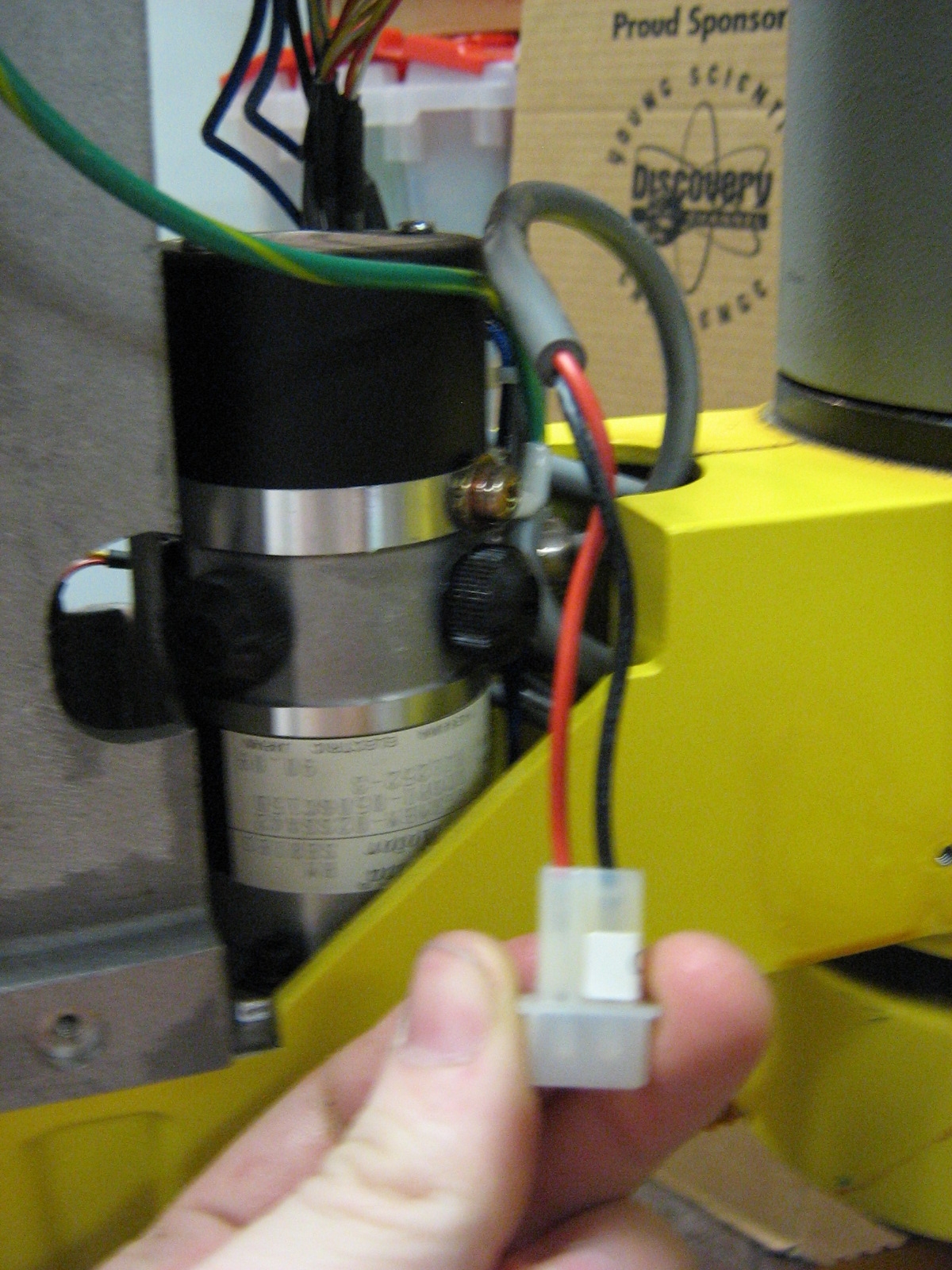
| Dc
Motor for Z axis and encased optical
encoder assembly in case. Brush points are encased by outer black
covers. Red / Blk wires are directly wired to brush DC motor. I like how the whole system is connector-ized. As this is an industrial machine, I was expecting long wires -soldered connections to reduce mtbf. Connectors made swapping in replacement hardware a 'snap' |
 |
 |
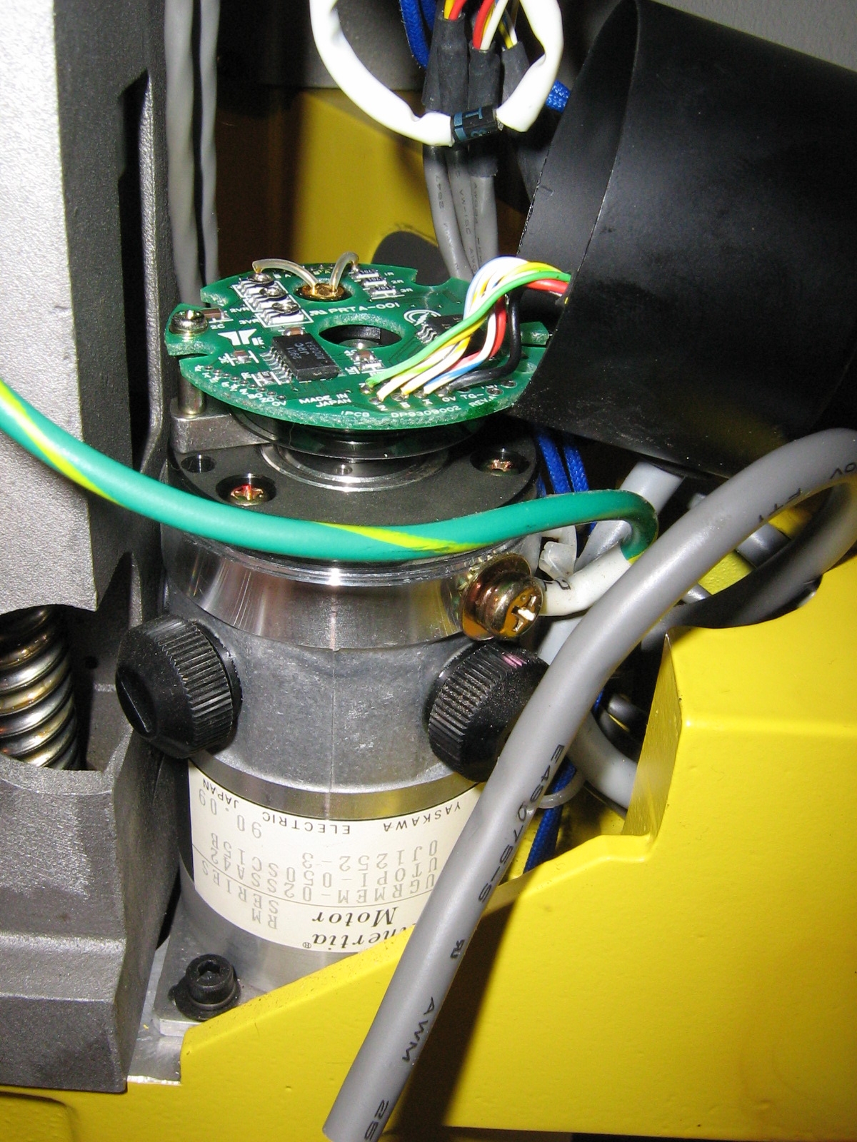
| Shown right is the z-axis motor assembly. The cover for the encoder
assembly is removed. Using the feedback lines i was able to scope out
the square-wave manchester position encoding. Note optical disk assembly and visible LED for optic feedback. Motor assembly is attached via belt to worm-drive for z axis movement. Damping device appeared damaged and was removed. Stepper motor 'locking' will be used instead |
 |
 |
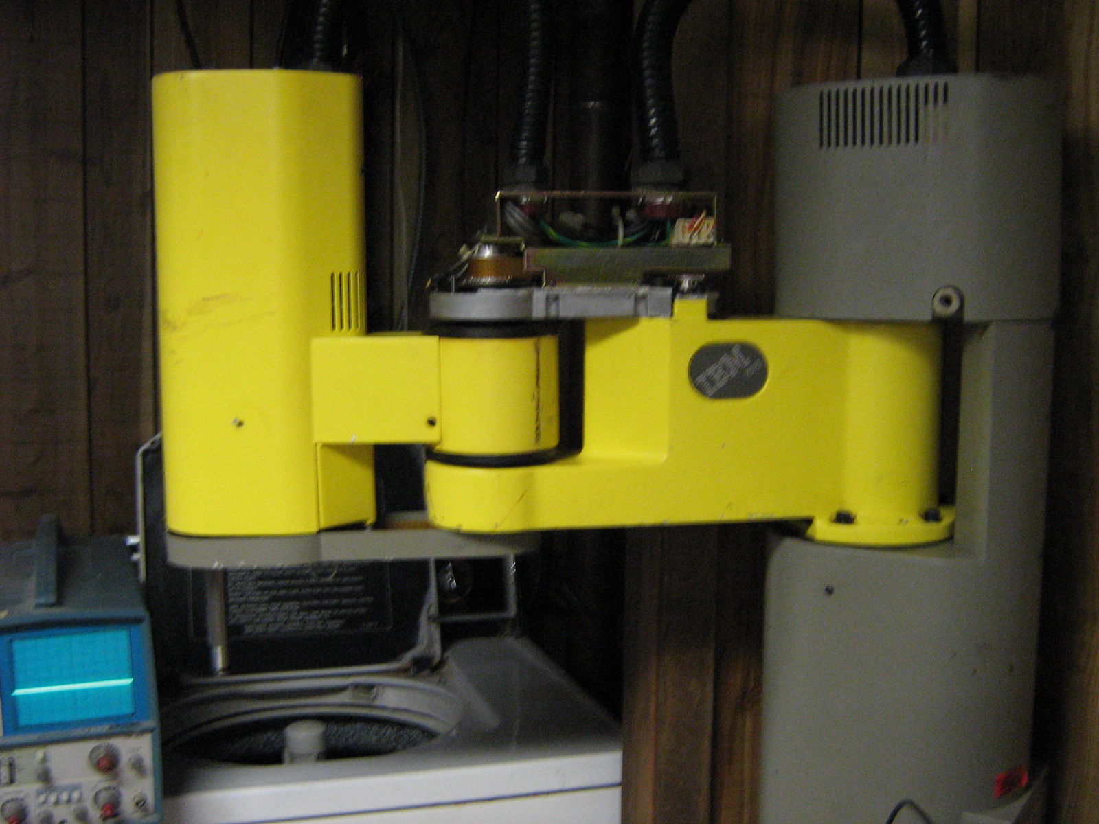
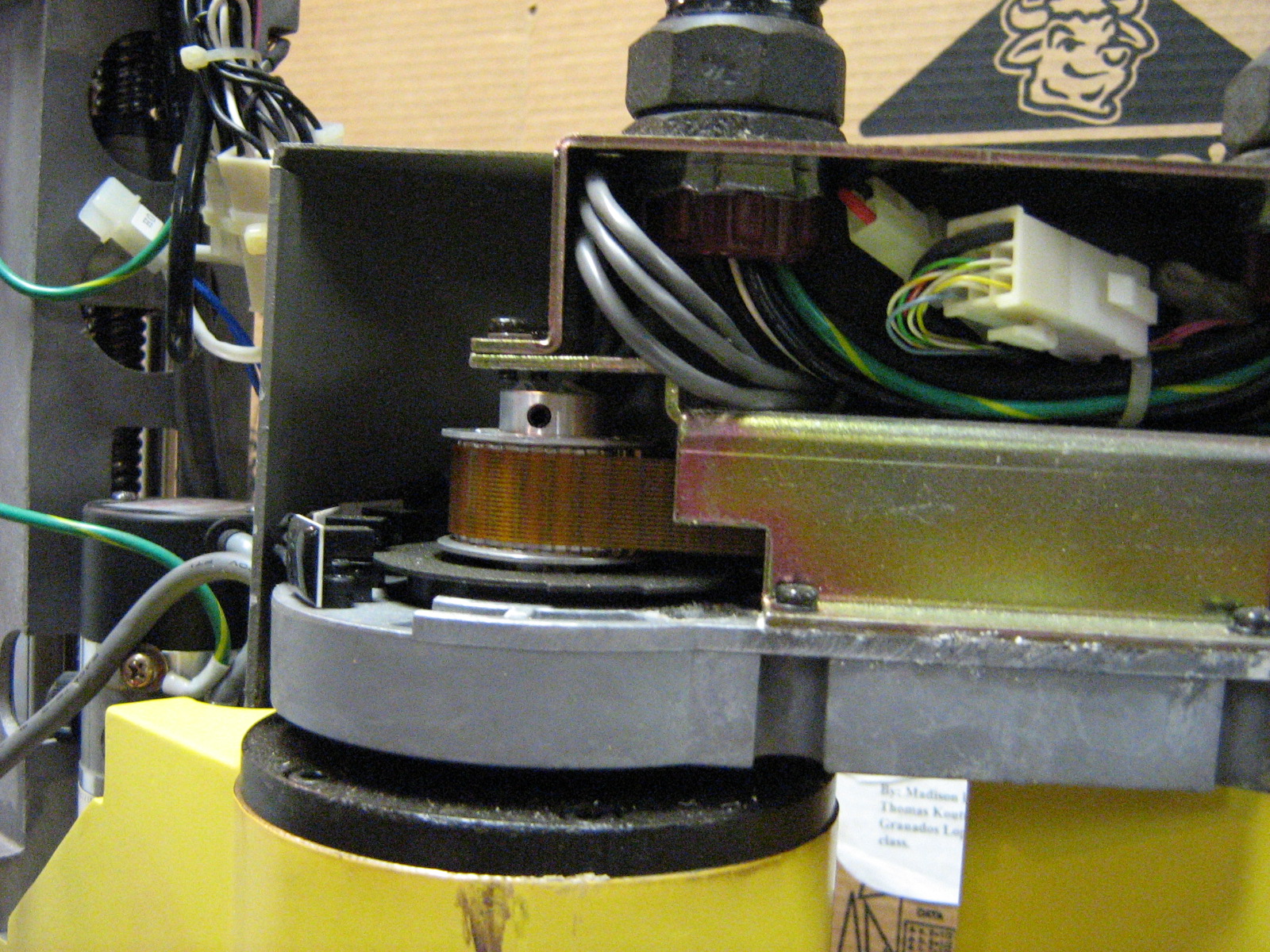
| Theta 1 drive point, including drive motor (far right) belt assembly for harmonic drive. | 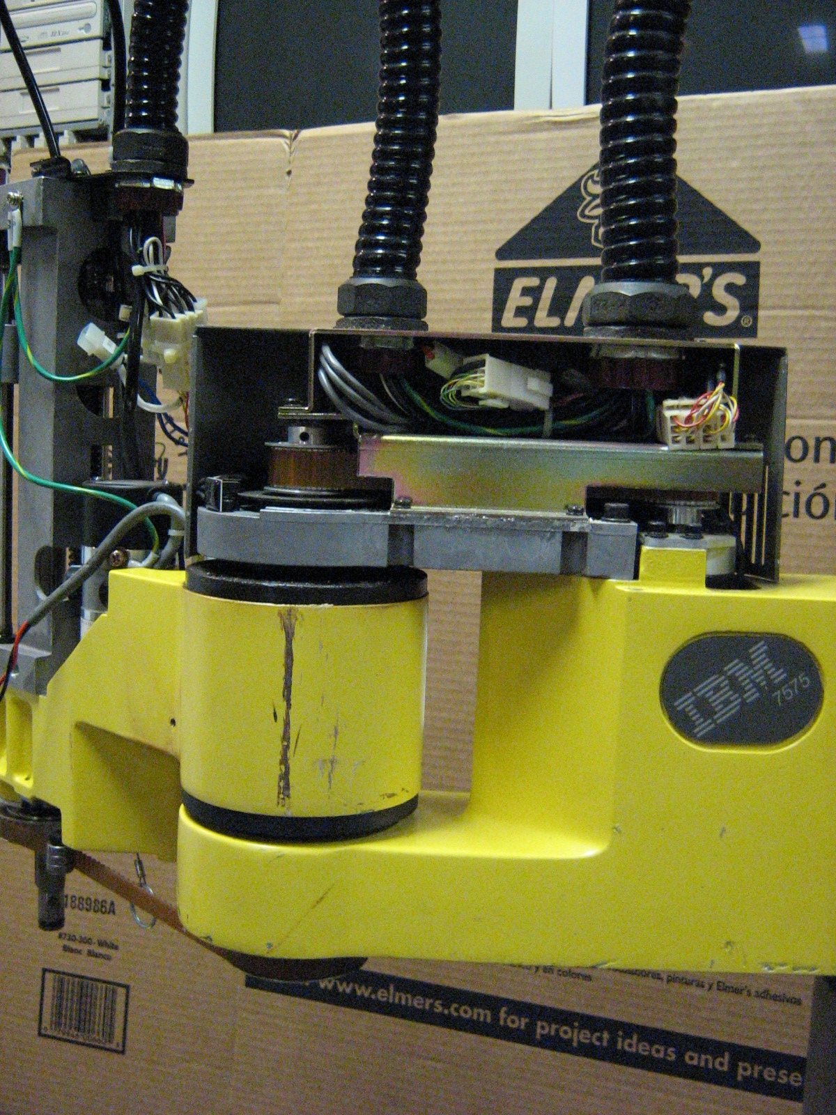 |
 |
Swapping In Stepper Motors
| Descriptor | Image/ Media | Image / Media |
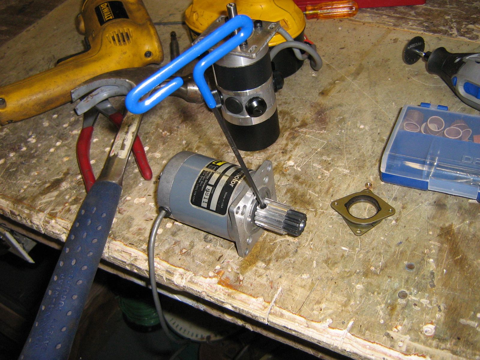
| Adapting stepper motor to shaft for main belt assembly. The stepper crufted from RPI Eclub was slightly smaller in shaft diameter than the existing belt cog, a sliced up piece of copper tubing was used. Tightening the spline and making small modifications allowed for a cheap collet. | 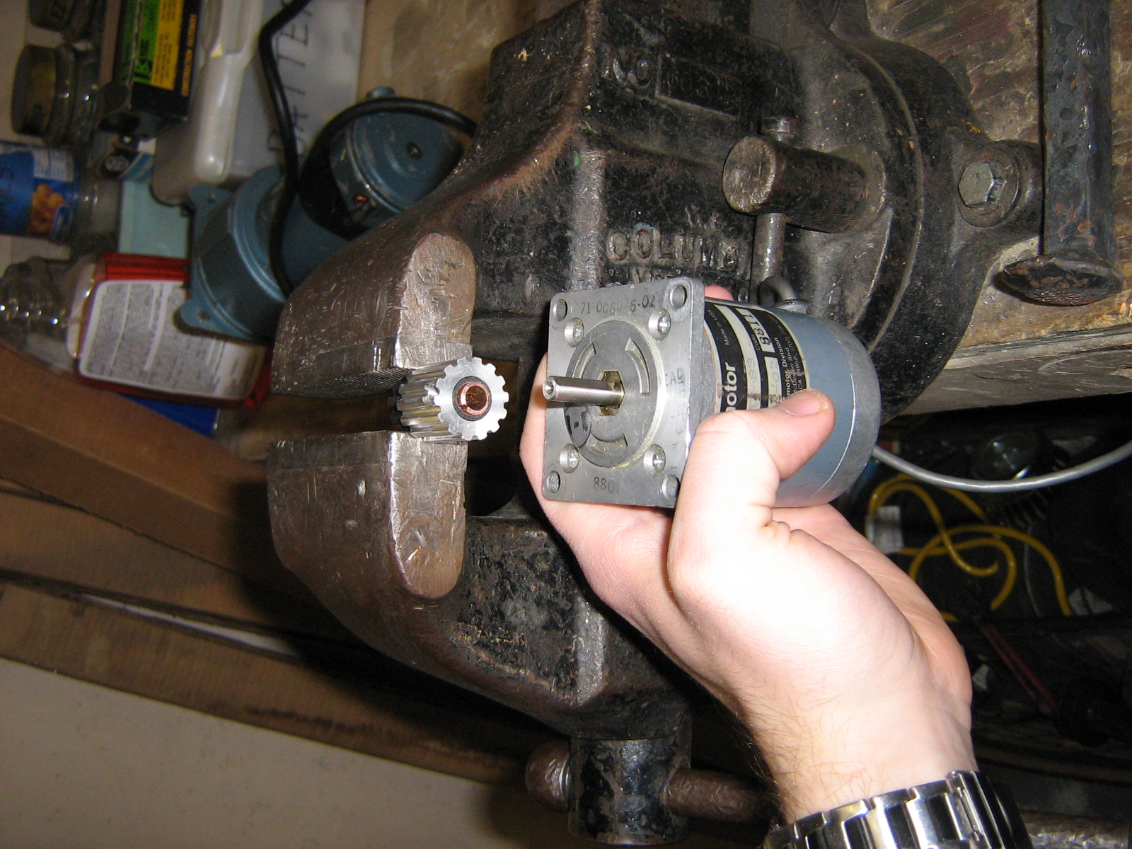 |
 |
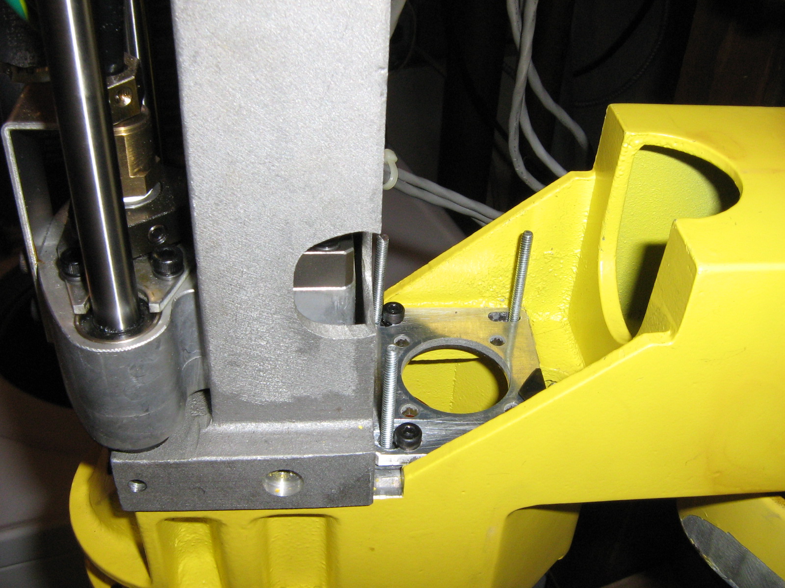
| Removing the older DC brush motor and adding in an adapting in a plate for the stepper motor. Long threaded bolts were used for tensioning the stepper motor to the robot. |
 |
 |
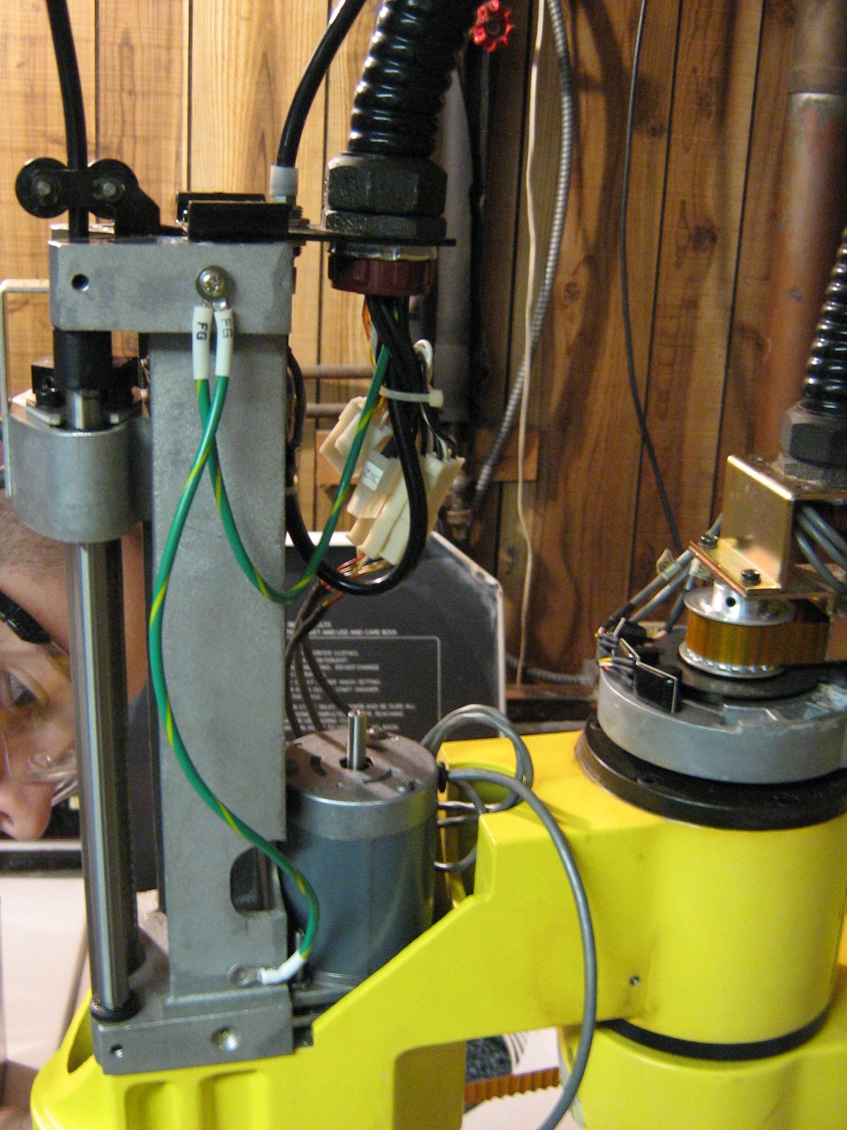
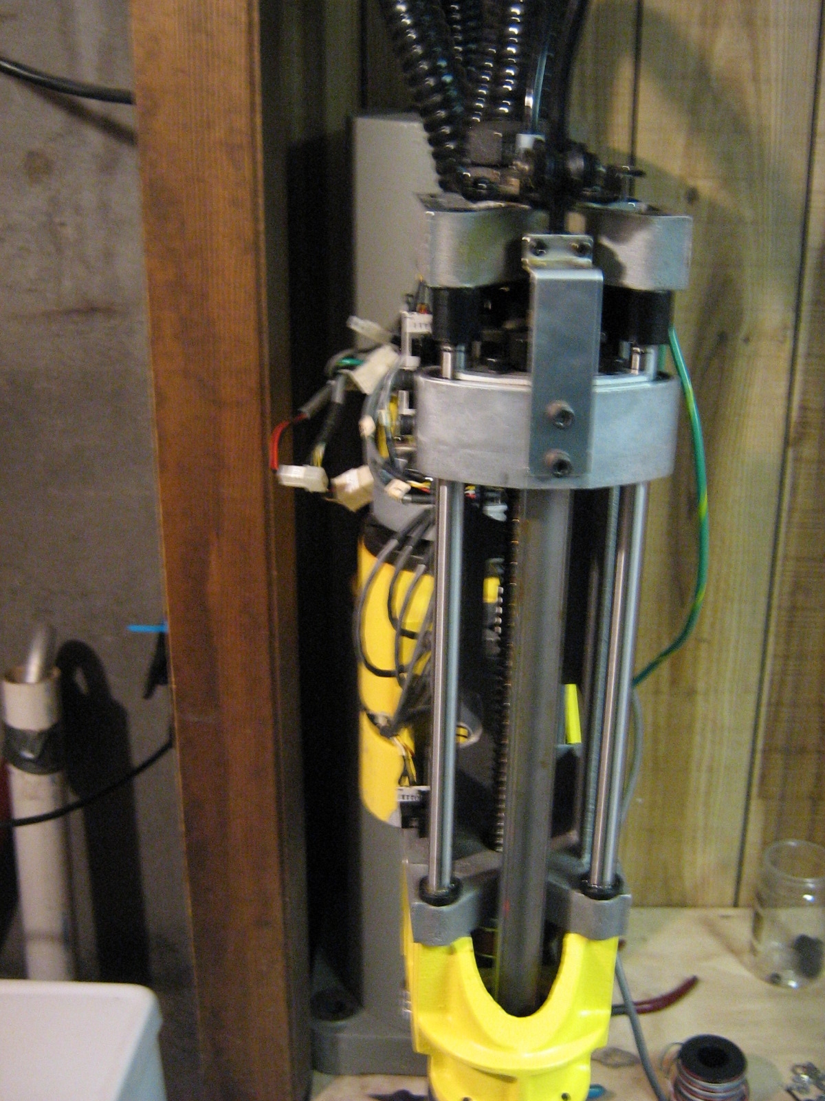
| Finally
the stepper motor was added in to the z axis drive. Note the 'snug'
fit. This was the largest 'scavenged' stepper motor i could find
at the time. Unfortunatley it lacked any formal datasheet and holding
torque estimations were used to determine the operating characteristics. To test holding torque of an unknown 4 wire stepper, the motor drive was commanded to hold a position, and mass was added to a lever attached to the motor shaft. The moment on the motor axis and the mass require for it to miss a step was used as the oz-in estimation for the motor. Unfortunatley, using an unproven stepper perf-board motor drive with current limits to measure the torque results in the measurement of either the motor torque, or the stepper driver's max holding current, whichever is the lesser : ) |
 |
 |
Early Stepper Motor Driver Hardware
| Descriptor | Image/ Media | Image / Media |
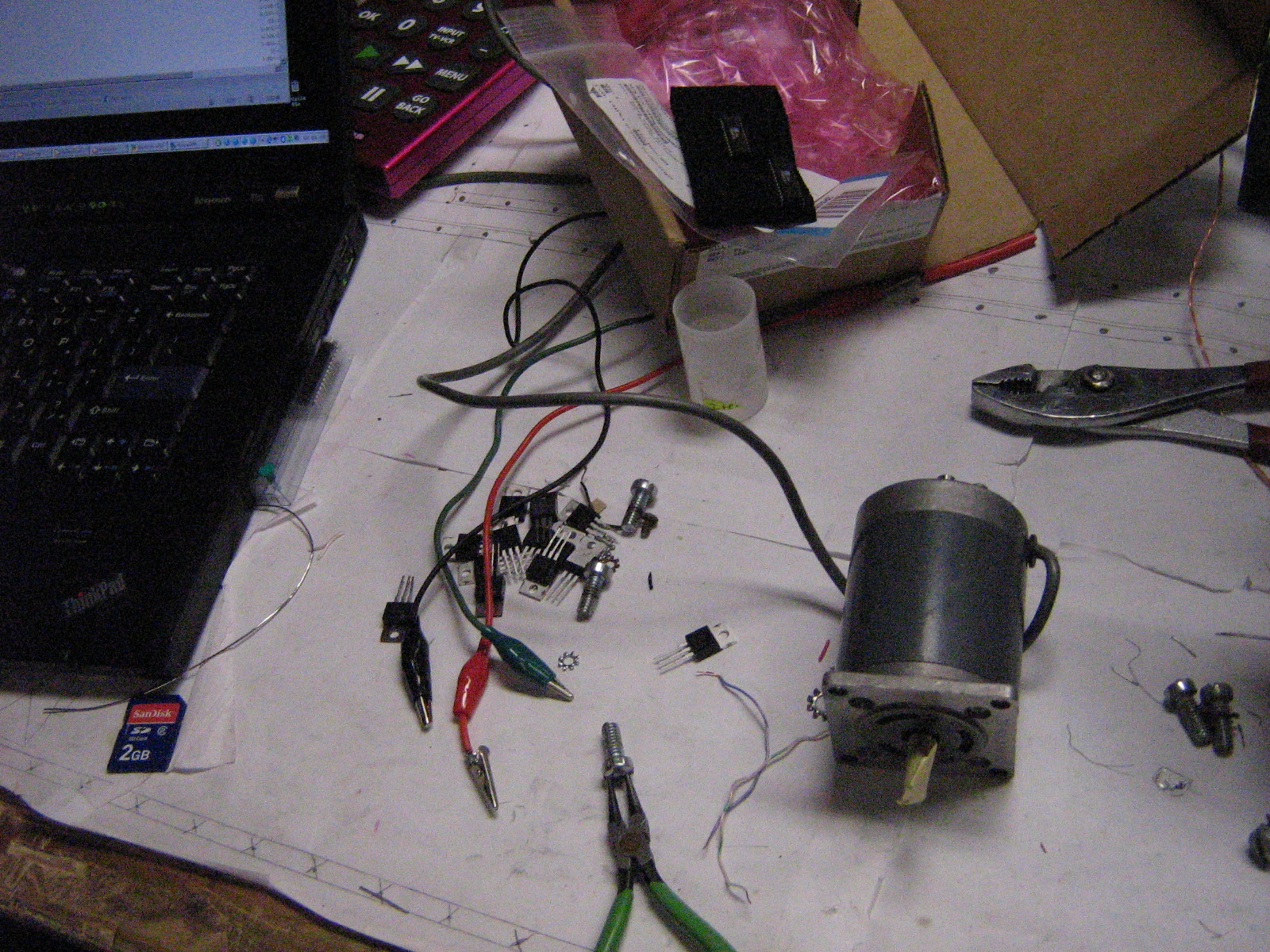
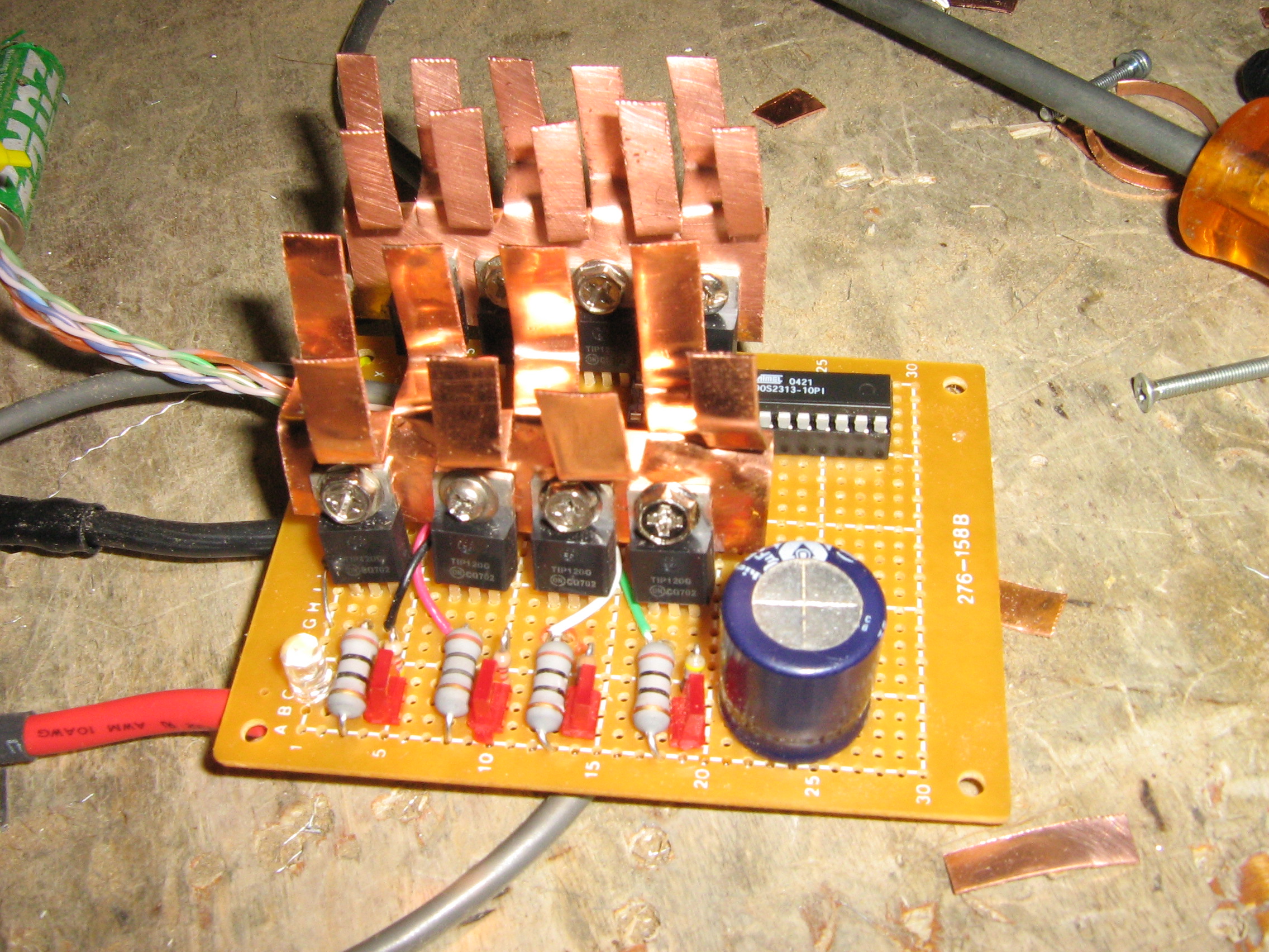
| To
test drive the stepper motor that me and anthony added to the robot, i
crafted a perf-boarded
Stepper motor drive, intended to drive two stepper motors. This is a
power-resistor pull-up style single ended driver (pull, not push-pull) This drives the Z Axis stepper and Theta 2 Stepper. Copper Heatsinks fabricated for thermal dissapation (namely when locking steppers) |
 |
 |
Brush DC Motor Encoder Hardware Debug
| Descriptor | Image/ Media | Image / Media |
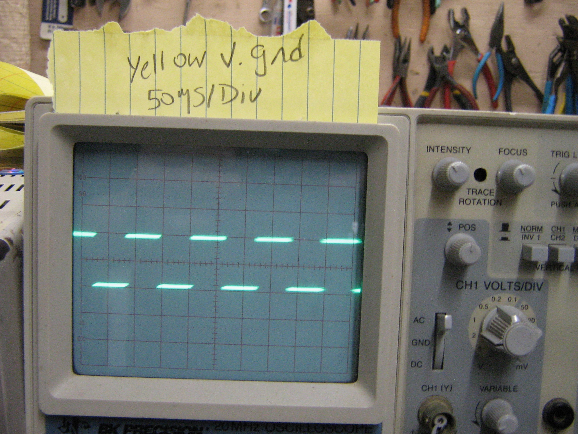
| The
encoder signals displayed at 50us / Div. DC brush motor operating at 5V
(instead of 12) and the output signal is between yellow and ground. The
yellow-ground signal is plenty of the purposes of the initial testing,
and will be used in the interrupt / brush dc control scheme. (Note, im @ home, thus the crt-scope) |
 |
 |
| DISASSEMBLY
DOCUMENTATION |
STEPPER MOTOR INSTALL | DRIVER HARDWARE | IMAGE DIRECTORY |
| From the sponsors: |
If you have questions or comments, shoot over an email.
| Comments: |
 HTML Comment Box
is loading comments...
|
Dane.Kouttron
Rensselaer Polytechnic Institute
Electrical & Electrical Power
631.978.1650
