Dane.Kouttron

[2.10.10] Super Quick UV Exposure Box

[OPERATIONAL]
What? 
A box for surrounding a UV pcb board with UV light,
(used for exposing the board)
The transfer quality is orders of magnitude better than the printer methods ive used and the final product is rather spiffy, SMT is far easer to do on a repeatable basis.
<WARNING UV is Bad for eyes, take precaution>
* Do double sided pcb exposure!
* Sanitize Things!


Layout
Components Construction Results IMAGE DIRECTORY

Simple Layout of Project

Descriptor Image/ Media
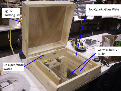
Basic Device:

Image pre-painting & pre- 'skirt' addition
UV bulbs and transformers on bottom portion of box

Transformers kept apart from UV sources


Components
Descriptor Image/ Media Image / Media
Components:

  UV bulbs (8W) X 2
Purchased from:
Link


Ballast
Class P, designed to drive 2 uv tubes
120VAC input

purchased from:
Link


Molex Connectors
Recycled molex connectors from ancient pc power supplies


Construction
Descriptor
Image/Media Image/Media
Making a Box:

I used two 6 ft 1X4's to make the top and bottom portions of the box. Standard caulking was used to


Make risers for the uv bulbs, i used pcs of plastic,

A mirror tile was inserted below the holders to reflect some light from the UV bulbs.
Make a ghetto uv bulb socket out of spare molex connectors,

They fit suprisingly well :)
Mount the UV bulbs in the ghetto sockets
(zipties hold the molex connectors well)

zip up any spare wires from the UV ballast.
Mount 2 pcs of wood for the glass holder frame.

Use glass from an old scanner (transparent to UV)

Use rubber hose to hold in glass (2nd pic)
Add hinges and an identical top
(add 2nd set of uv bulbs if necessary)
make sure it closes without a gap.

next up: the safety open = off switch
Recall:

high power UV = bad for humans

so dont look @ it, if you see it its bad, add felt or something opaque
ON-OFF SWITCH

Note, you dont really want to jostle anything when you fire up the uv lamps, choosing a nightmarishly large switch may cause things to shit around a bit.

Results
Descriptor Images Images
2nd and 3rd
attempts
inspecting the pcb's

Adding a 'skirt' (added 2-20-10)
(prevent uv light from escaping)
Descriptor Images Images
Make the skirt out of opaque material, in this case, material was used from a carry bag obtained from a local career fair. Its been in the lab foyour there nwor months, and not its going to be finally used...
The final product Before and after spraypaint. plastic tubing used to create an overhang between UV and cloth (easier to close)
Adding a 'UV IS ON' indicator (added 2-22-10)
(check if its actually working without destroying your eyes)
Descriptor Images Images
UV is on led, tied to an LDR. When light is present inside the box, LDR -> 5k ohm, and the led turns on.
The reason for building this, is these transformers are designed for 2 bulb operaton, if one fails, neiher operate. The led indicates if there is light present in the box.


Image of schematic and ldr setup. a battery was used as there wasnt any low voltage present in side the box, the heaters for the bulbs were only on during startup.


Adding a Diffuser (added 2-23-10)
(Spread out the UV, prevent paralax)
Descriptor Images Images
Constructing a diffusion layer between the source and the glass panel


Diffuser is constructed of 2 thin film plates of lcd backligt diffuser and one thick plate backlight diffuser. Wax paper and uv transparent scanner glass would also work well.

transparancy shown on top glass plate


Layout
Components Construction Results IMAGE DIRECTORY

Overall:
Need to add difussers to prevent minor parallax issues.

Created by:
Dane Kouttron
Rickey Williams
transistor-man.com http://rickywillems.myrpi.org/

Comments:
HTML Comment Box is loading comments...


Dane.Kouttron
Rensselaer Polytechnic Institute 
Electrical & Electrical Power
631.978.1650