Dane.Kouttron
[11.22.11] Theta0 V2: ServoMotor→Stepper Emulator [36v50A]
| What? Open Hardware DC Servo Motor controller talored for:
Sample
Files for each operating mode are available below
|
 |
 |
| This project documents the design and operation of the Theta0 V2 motor controller |
| What? | Components | How To | Results [DATA SETS] | Firmware | IMAGE DIRECTORY |
| What? | Image/ Media |
|
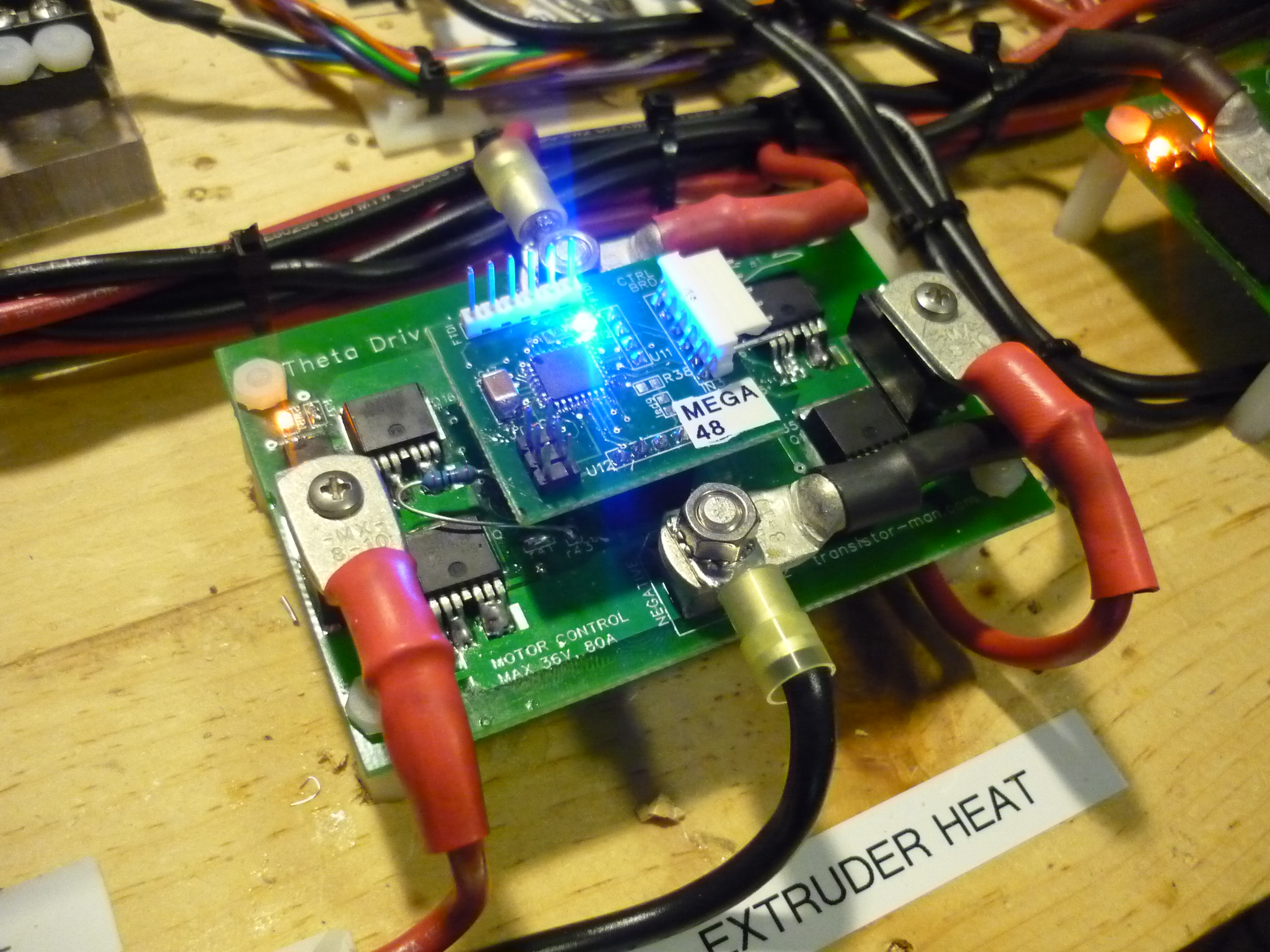
Theta0
V2 was a quick proof of concept high current dc brush motor drive. It
was sent out initially using Advanced circuits 'BAREBONES' service, which provides
a quick turn, low cost board, without the bells and whistles. After populating and testing the board, I sent out the final revision,Theta0 V2, documented below 'Theta 0' literally derived its name from its intended purpose, controlling an axis on a robot arm, namely the theta 0 axis. |
| What do I need to make this work | Image/ Media | Image / Media |
| AVRISP MKII, or AVR JTAG ICE |
||
| FTDI-> RS232 to USB cable,
or rs232 level shifter |
| How to: | Image/ Media |
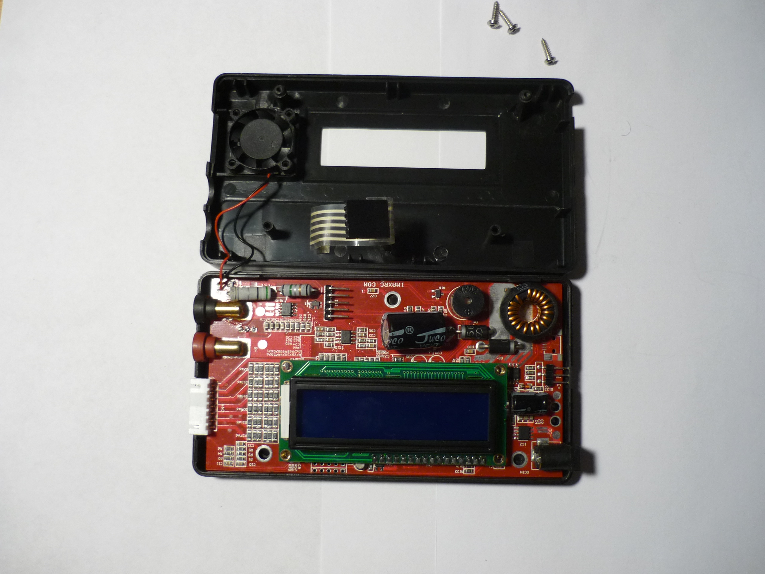
| Open it up |
|
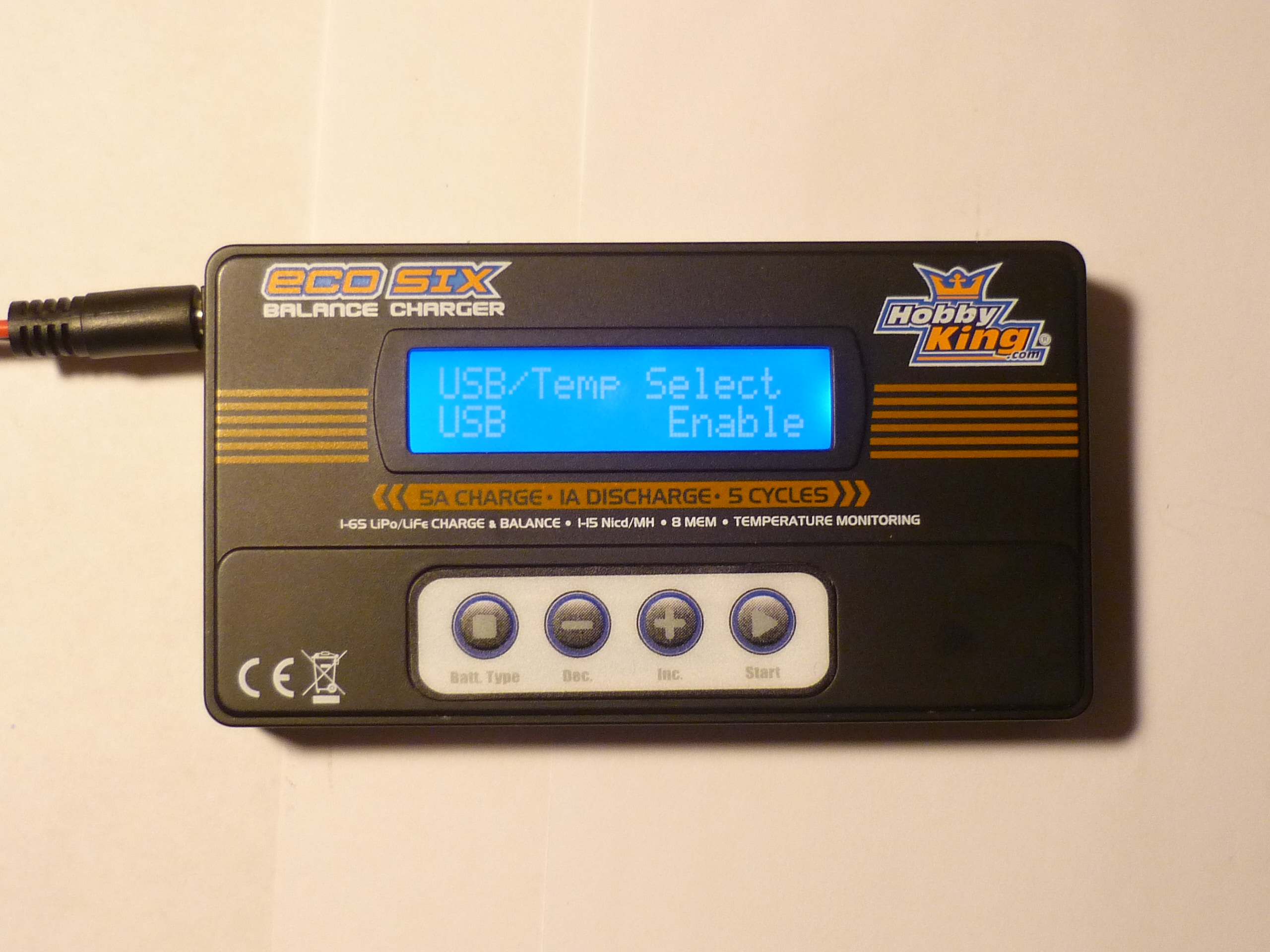
| Enable
USB? |
|
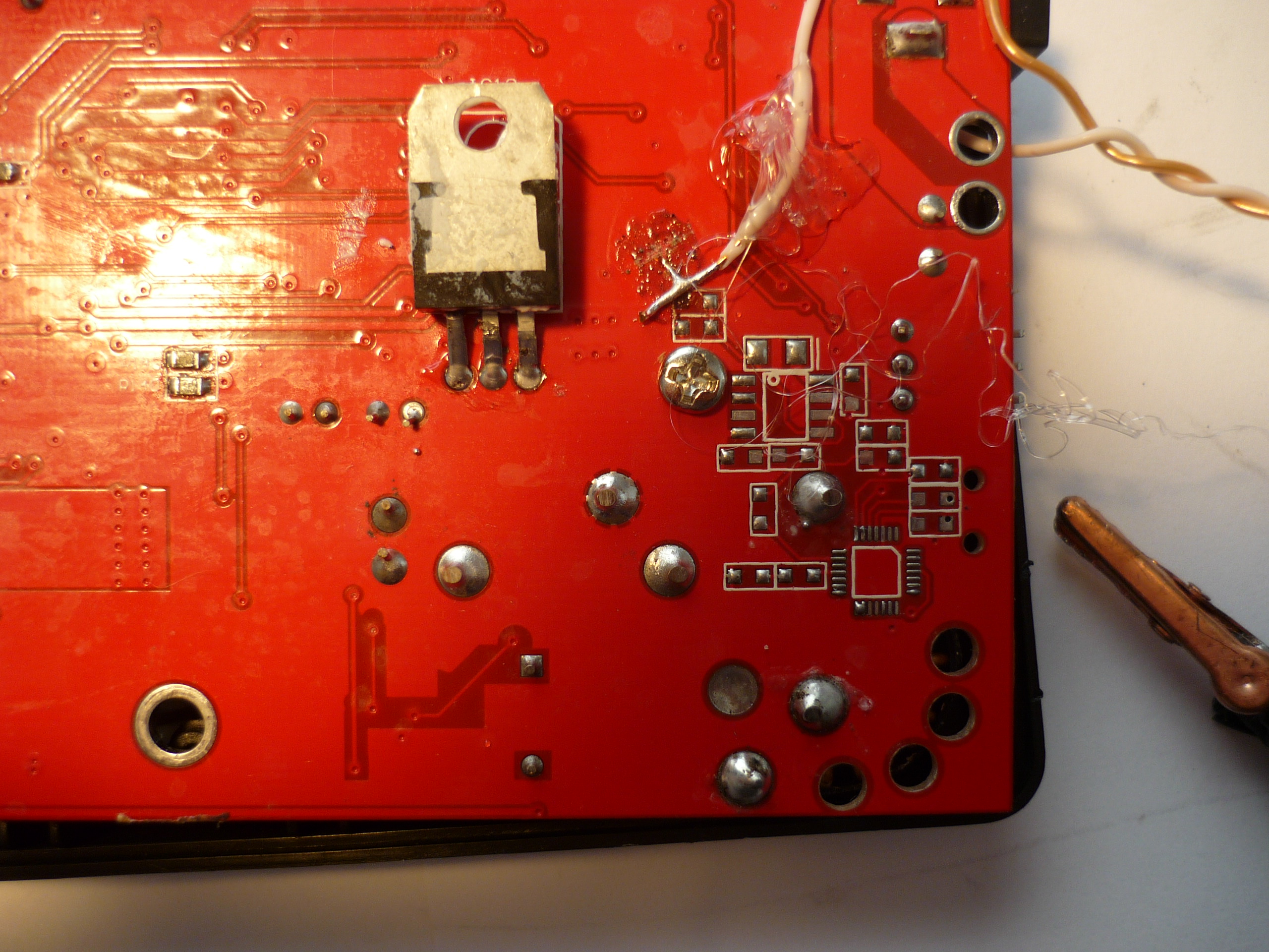
| Find MCU Transmit |
|
| Oh
hey, there's a Semi-Jtag Interface |
|
| Looks
like An FTDI chip would live here: |
|
| Binary
RS232 TTL Datastreem AHOY. Shown |
|
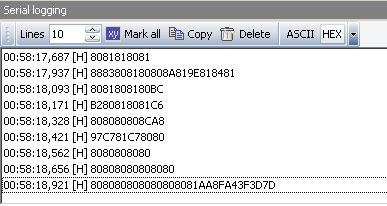
| SOUNDS
LIKE DATA The idea that this board is used with a different population option for more functionality, indicated that the coms protocol should be similar to an existing, more functional product. pulling up putty, at 9600 9N1, the datastream looked repeating, i pulled up miniterm, and set the output to binary parsing instead of ascii, and lo, non-garbled data. Initially i thought it was odd that the data came in repeatable chunks at 9600 9N1, versus 8N1, but it turns out it was miniterm/the ftdi cable i was using just getting confused |
|
| Piping
the data into LOGVIEWGrab
a copy of 'LogView' from the following: (make sure to select english, if you don't speak german!)http://www.logview.info/vBulletin/downloads.php Install/select the following INI http://transistor-man.com/files/echo-6/config.ini |
|
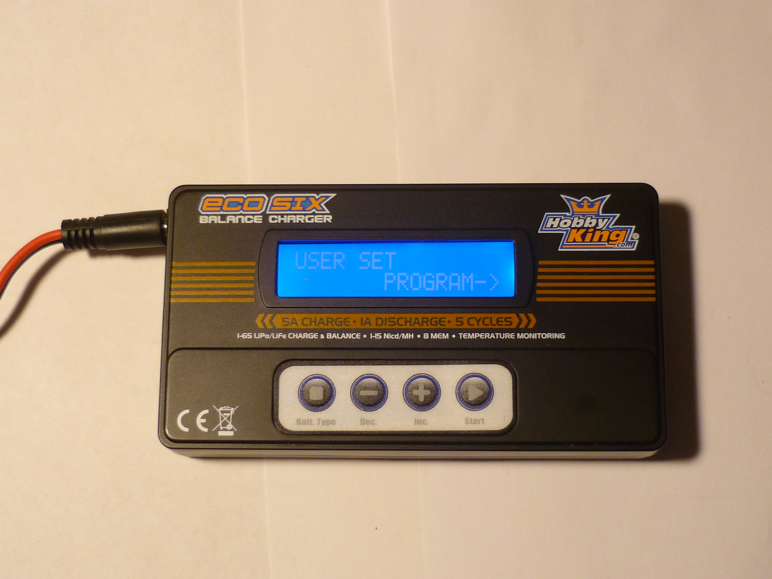
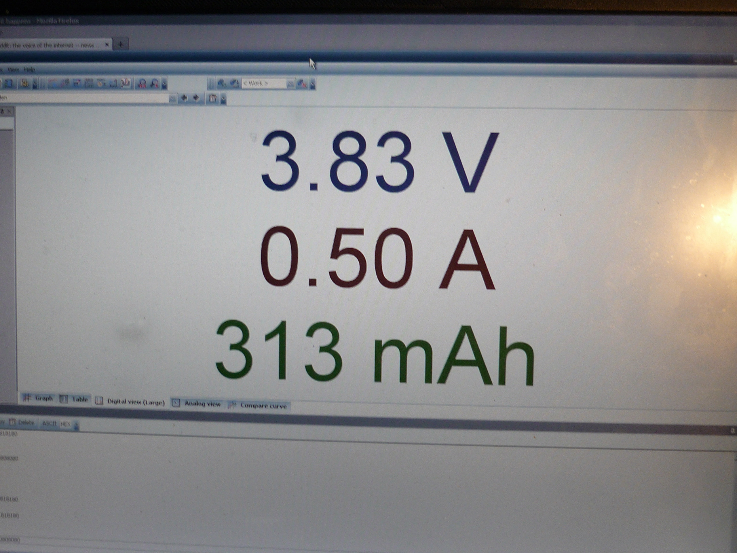
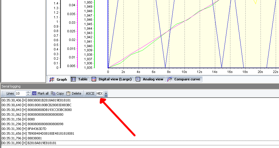
| Get
it to RUN! With the FTDI cable plugged in and the correct com port selected, select the green 'com' button. If the correct INI file (available above) and the program is connected, there should be a stream of data available. (check the red arrow) Logview allows for a number of customizations as well as data output formats, its a really excellent piece of free software. |
|
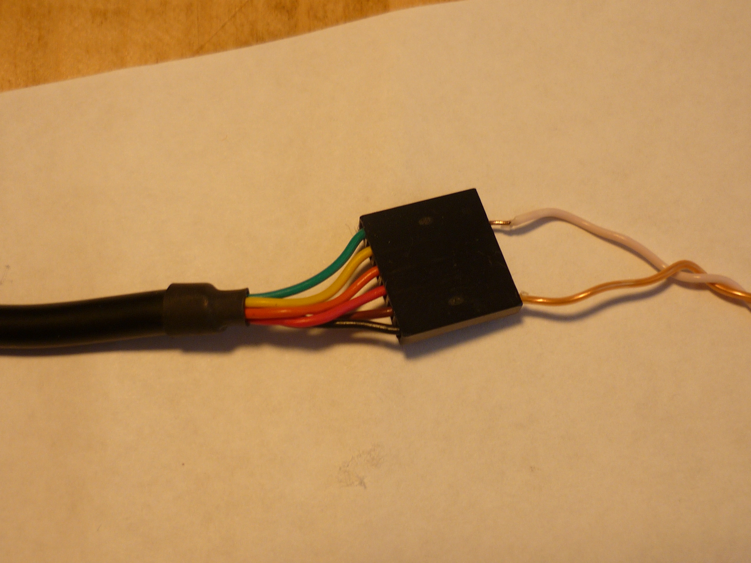
| Kelvin'ing
(sort of) Attach the balance connector (tacked from large 6 pin balancing connector) to the cell at an 'unloaded point' The charger bases its decisions (for single cells) on the main power lead voltage. As there can be ~5A flowing through these cables, the voltage observed at the charger is equal to: (cell voltage - [I Charge * R Cable]) so the measurements and cut-off points arent very accurate, however, the balancing connector also has an adc that's constantly monitored (1hz) attaching the balancing connector to the cell before the point where the charge/discharge cable connects provides a more accurate, unloaded measurement. |
|
http://ntur.lib.ntu.edu.tw/bitstream/246246/85923/1/36.pdf
| Sample DataSets | Graph | DataSet |
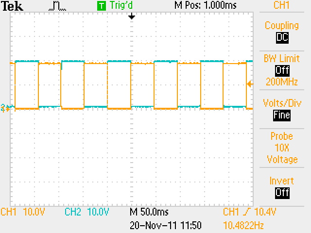
| Controller 10 Khz Commutation, 1A load (resistive) | 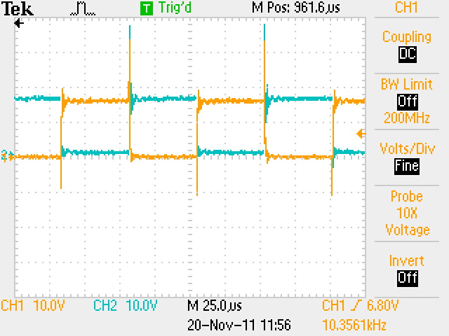 |
|
| Controller
at 10hZ comutation, 1A load (resistive) |
 |
|
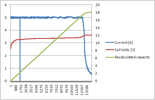
| Single
Scooter Pack block, 9P 26650 5A charge plot
|
||
| Firmware | Image/ Media |
|
|
This project complies with the OSHW 1.0 definition
(There's
other photos in the photo gallery)
Concluding
Remarks:
As my first 'flying cap' bootstrap motor control attempt, this worked extrodinairally well, after some minor modifications.
if you have questions or comments, shoot over an email.
References:
| Comments: |
|
HTML Comment Box
is loading comments...
|
(be
careful, im not responsible for your exploded battery pack)
Dane.Kouttron
Rensselaer Polytechnic Institute
Electrical & Electrical Power
631.978.1650
