| Step |
Descriptor |
Image
/ Media |
| Find
/ Scavenege |
Here's
an image of the LCD, unmodified. sitting there, alone and broken, at
the gallows, off to some mashing device or a giant heap of trash..not
so fast. RECYCLING! |
|
| Well
nothing gets power so, off to the power supply |
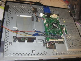
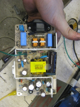
Here's
the LCD
Power supply (PSU). Its job is to take the 120 RMS wall AC and convert
it into a useful set of voltages.
it unfortunately
doesn't do
anything.
After checking the psu top to bottom i found that the main switching IC
(DATASHEET) wasn't actually doing anything Two reasons why this could
happen:
1. A
fuse was blown,
somewhere
2.
something on the
output side of the power rail was shorted
3. The
IC failed. <winner> |
 |
| Re-Enabling
the IC |
The
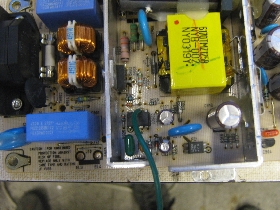
power supply wasn't particularly doing anything. 120VAC entered in on
one side, but no switching or activity was observed on the other. The
switching IC is actually common (a spare was found in an old ATC power
supply) I tacked a wire to the 'enable' line of the IC in hopes of
starting it back up. No dice. |
 |
| (Better
view of connectors) |
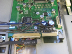
Here's
the main board |
 |
| Cheat |
After
deciding to
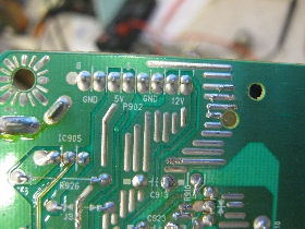
reverse engineer the power supply connector, i noticed that on the
other side of the board, it was labeled.
THIS IS AWESOME.
so the next step was to feed in the appropriate voltages and see what
happens.
TLDR: Label your PCB traces |
 |
| check
it |
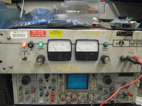
The
next part is
crucial. after tacking wires to either supply and throwing some input
caps in place, run both supplies from power supplies with ameters. You
want to know how much either side consumes. This LCD pulls a little
over 1 A at 12v, and 300ma at 5V. |
 |
| Package
it up |
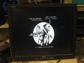
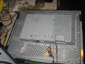
It
works, package it back up with the handful of screws you actually saved.
(image of back of monitor with metal emi shielding back on) |
 |
| Tie
in the wires and cobble together a
new PSU |
I
used a 3 A 12v
PSU, and used a buck converter to provide the 5v (buck converter from
12v cell phone adapter that i found) |
<image
unavailable> |

