Dane.Kouttron
The
Vibrobyte: Haptic Feedback
What?
A
wireless, haptic interface featuring a quick refresh rate, high current
output for driving variable loads / feedback devices, that can run from
a variety of power sources.
The size of a pack of gum
|

|
|
| This
page serves as a backup of the documentation hosted on the team
wiki, http://bluwiki.com/go/RPI_Haptics,
in a hopefully easier to browse, less cryptic fashion, with more uptime
:) |
| HMM?
|
Image/
Media |
The
vibrobyte is a wireless, reprogrammable, interconnectable reciever for
use in preformances; both local and co-located. It can run on a
variety of power sources, and can drive up to 4 seperate vibratory
motors, or dc devices, while changing color and communicating with a
master node at a high individual refresh rate. Devices are also
trackable via overead camera (each module has a high-power IR led).
High-speed, open source & hardware communications, the size of a pack of gum |
 |
The vibrobyte was presented at "Telemorphosis" at
ICMC 2008. Technical details were presented at the
156th ASA Meeting and
NIME 2009.
Listed @ the Acoustic Society of America:
J. Acoust. Soc. Am. Volume 124, Issue 4, pp. 2489-2489
| Basic
Roadmap |
Image/
Media |
|
The following outlines each step data must take from the
initial triggering to the actuation. Different groups are focusing on
different portions of this process, and some in-between portions are
being dealt with as they emerge.
- Conductor creates/maps vibrobyte
OSC data for display (GUI and input mapping in Max/MSP, PD, etc.)
- Data is sent to remote spaces
- OSC Data is transmitted (ports must be open,
remote space must have necessary hardware & software)
- (...continues as with local space)
- Data is distributed at local space
- Data is packaged (from OSC into a form suitable
for local transmission: serial packets, using Max/MSP, PD, etc.)
- Data is sent via serial to an Arduino
- Arduino echoes data to RF transmitter
- Each vibrobyte
RF receiver sends packets to the microcontroller
- Each vibrobyte
microcontroller interprets the packets and executes the command
- Outputs (vibrator motors) may be actuated
(need to be attached to performers)
- LEDs may be triggered
|
|
| Hardware
|
Image/
Media |
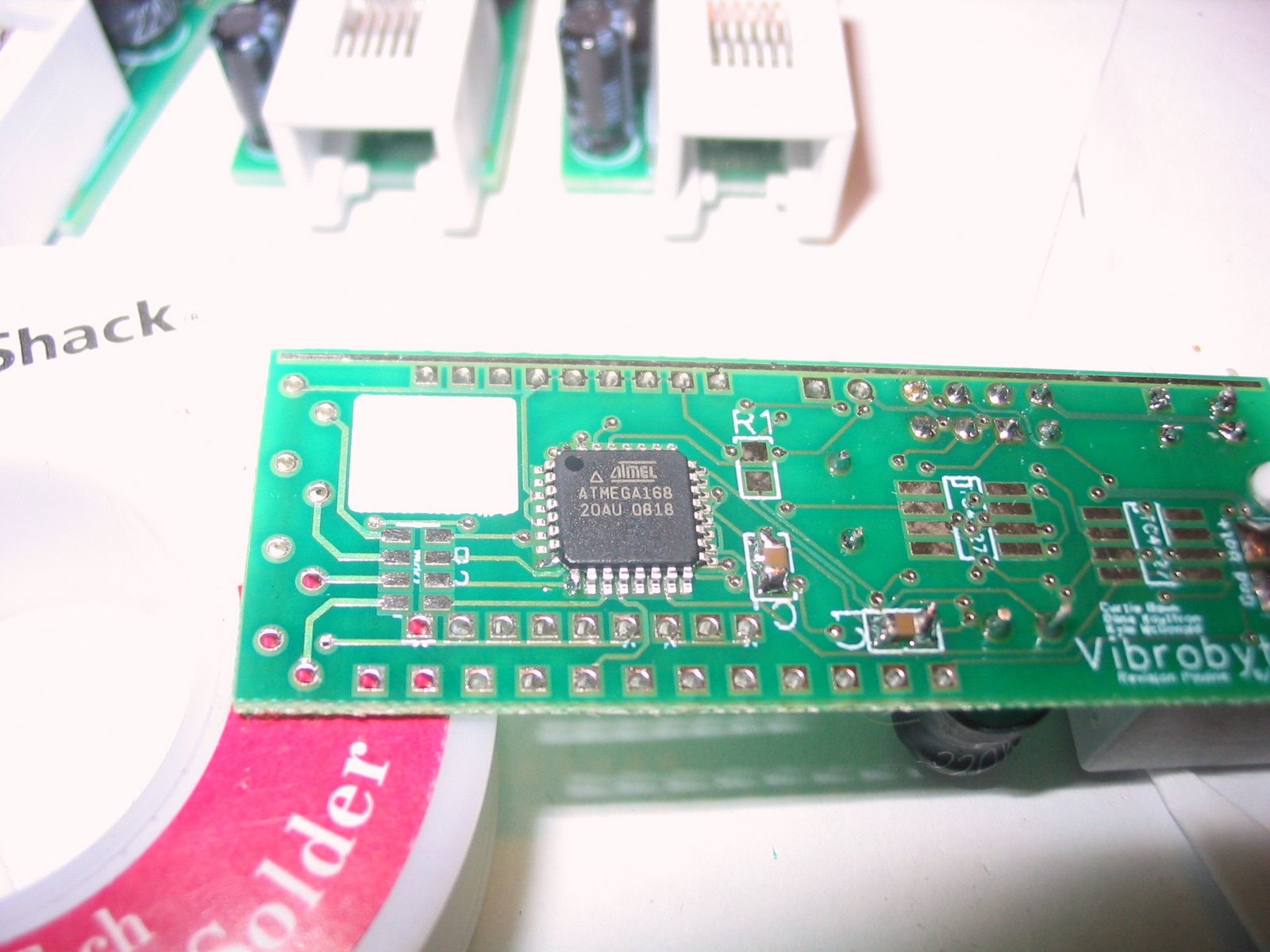
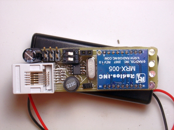
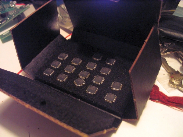
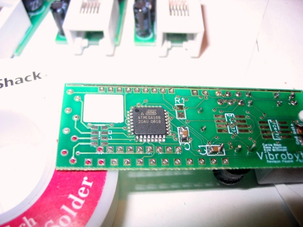
Here's
revision Pauline.
This was the 4th
revision of harware, moving from custom RF and underpowered attiny to a
ful size atmega168 and a 915mhz daughterboard
[Features]
- LEDs driven
directly from the 168, no transistor, and one quad resistor
- DC/DC step up
converter allows for multiple battery sources (2v->5v input)
- Correctly wired
RF receiver
- Correctly wired
LEDs
- Proper 3x2 ICSP
header
- 2-position DIP
switch with permanently "on" DC-DC converter
- Smaller SOIC
output amplifiers instead of through-hole (1 amp / pwm output)
- Evenly bright
LEDs
- Breakout into
through-hole contacts for unused ADC and other IO (side of pcb)
- Freepcb bac files: LINK
- Freepcb schema files: LINK
|
 |
[Pin
Mapping]
| Arduino |
Purpose
|
Functions |
Port +
Number |
168 Pin
|
|
7 |
IR LED |
PCINT23/ANIN1 |
PD7 |
11
|
|
5 |
Red LED |
PCINT21/OC0B/T1 |
PD5 |
9
|
|
6 |
Green
LED |
PCINT22/OC0A/ANIN0 |
PD6 |
10
|
|
9 |
Blue LED
|
PCINT1/OC1A |
PB1 |
13
|
|
3 |
Output1
Control |
PCINT19/OC2B/INT1 |
PD3 |
1
|
|
11 |
Output2
Control + MOSI |
PCINT3/OC2A/MOSI |
PB3 |
15
|
|
10 |
Output3
Control |
PCINT2/SS/OC1B |
PB2 |
14
|
|
1 |
Battery |
ADC1/PCINT9 |
PC1 |
24
|
|
 |
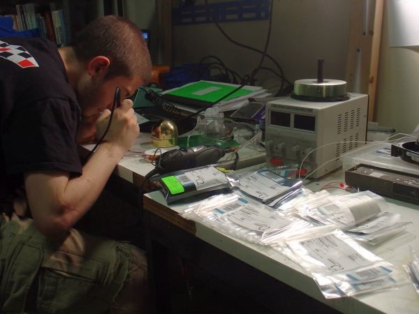
[Assembly Instructions]
- Solder the 16 MHz crystal
- Solder the diode, C1 (1uF) capacitors, 100 uF
capacitor and MAX756
- Solder the RJ-11 jack
- Solder the 22 uH inductor
- Test that the MAX756 is outputing 5V and using about
20-30 mA (pin 1 or 5)
- C2 (22pF) capacitors, R1 (10.5 kOhm) resistor,
ATmega 168 and DIP switch
- Test that Pauline is using 30-40 mA
- Add the ICSP header and try connecting with the
AVRISPMKII
- Add components for driving LEDs (quad resistor R2
and LEDs)
- Upload PaulineBlink
from the Arduino environment, the LEDs should flash (RGB, off, IR,
off); if not:
- Check the resistance between the 168 side of the
resistor and the positive terminal
- Check the resistance between the LED positive
terminal and the 168
- Make sure the solder is clean around the quad
resistor, and there is no cross-solder
- Add components for driving output
- Upload PaulineBuzz
from the Arduino environment, the motors should buzz (output1, pause,
output2, pause, output3, pause); if not:
- Check for cross-solder on the driver chips
- Make sure your motors are wired correctly
- Add RX module
|
 |
[Programming Via Avr Studio:]
- Connect the AVR ISP MKII to Pauline and open AVR
Studio.
- Go to Tools > Program AVR > Connect
- Under "Main", select ATmega 168
- Under "Program", select the "..." next to "Input Hex
File" and select Pauline.hex
- Hit the "Program" button
- Under "Fuses", next to "EXTENDED", "HIGH" and "LOW"
enter 0xF8, 0xDF and 0xFF (same as Arduino fuse bits)
- Hit the "Program" button
- Under "Lock Bits", next to "LOCKBIT" enter 0xCF
(same as Arduino lock bits)
- Hit the "Program" button
|
 |
[Programming Via Arduino
Environment]
- Change the above settings in AVR studio
- Open
C:\Documents and Settings\username\Application
Data\Arduino\preferences.txt
- Change
"upload.using=bootloader" to "upload.using=avrispmkii"
If this
doesn't work, you may need to disable the AVR Studio drivers and use
the libusb drivers instead. There are some notes here on doing that.
|
 |
[Operating
Notes]
- When
reprogramming or updating firmware, via the ICSP header, output 2 will
oscillate.
- When not in use,
remove batteries from pauline to prevent parasitic draw (70ma). Pauline
pcb's can stay in standby for well over 20 hours from 2 standard NiMH /
NICD 2000mah rechargeable AA cells.
- When choosing
rechargeable batteries for performances, be sure to look for data
regarding output current, and charging current, most unmarked AA / AAA
style cells require overnight charging, whereas certain cells accept
larger current charge rates.
|
|
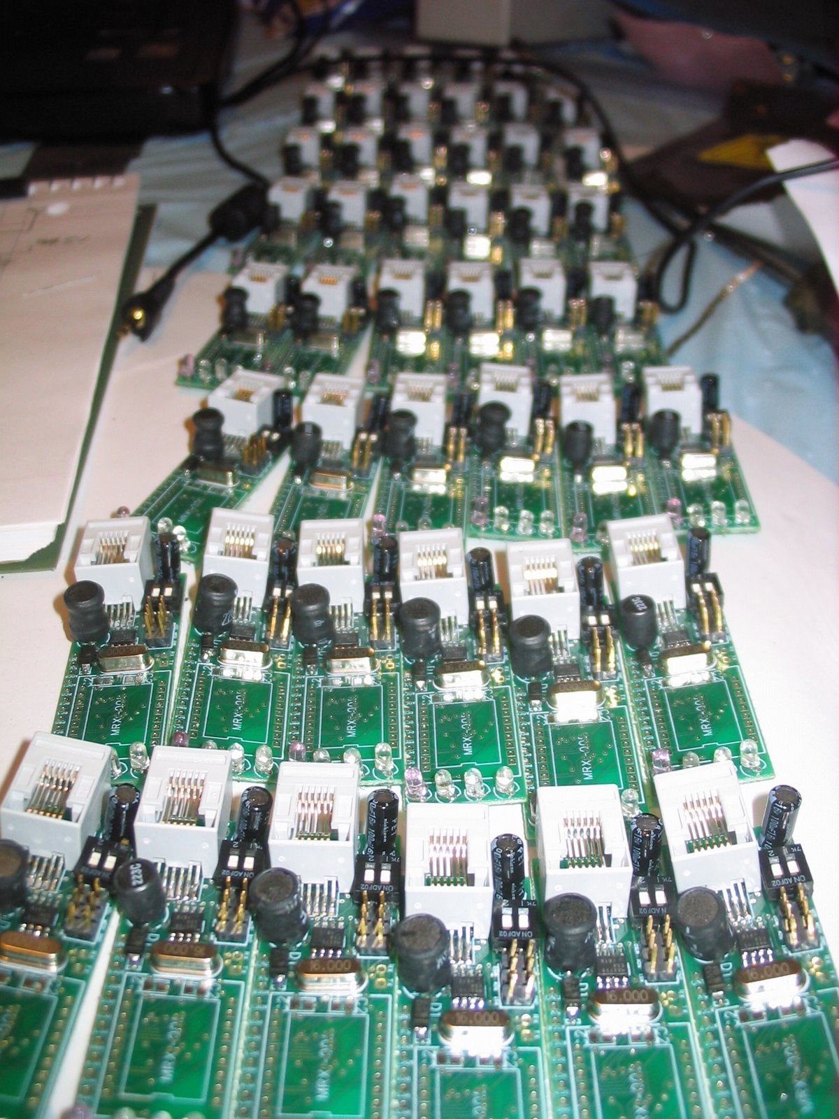
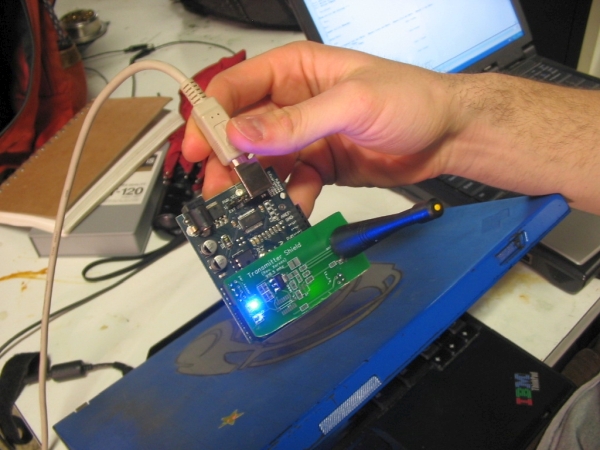
[The Transmitter]
Attached to a
users computer, the transmitter consists of an arduino, 915mhz transmit
shield and an rf amplifier
<code for
transmitter shield> |
|
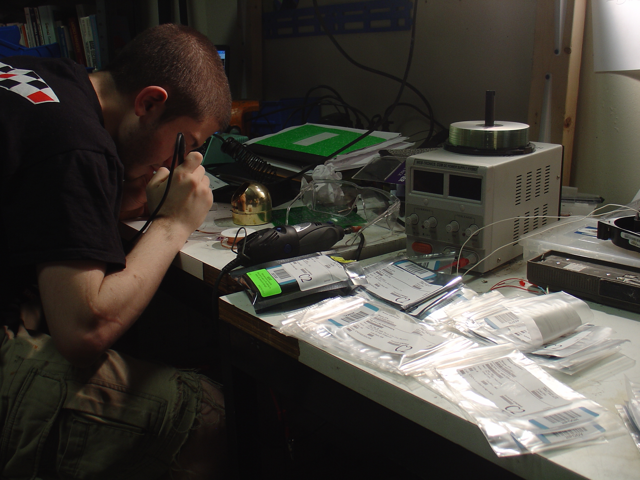
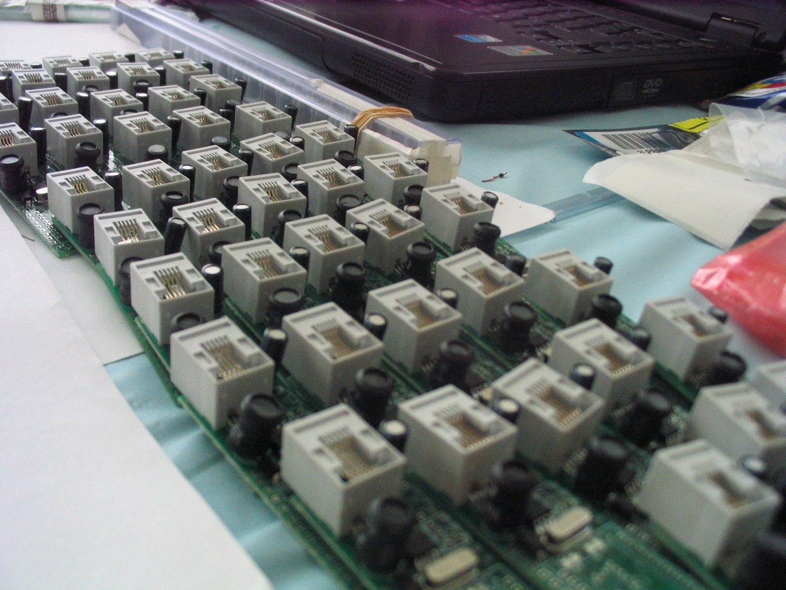
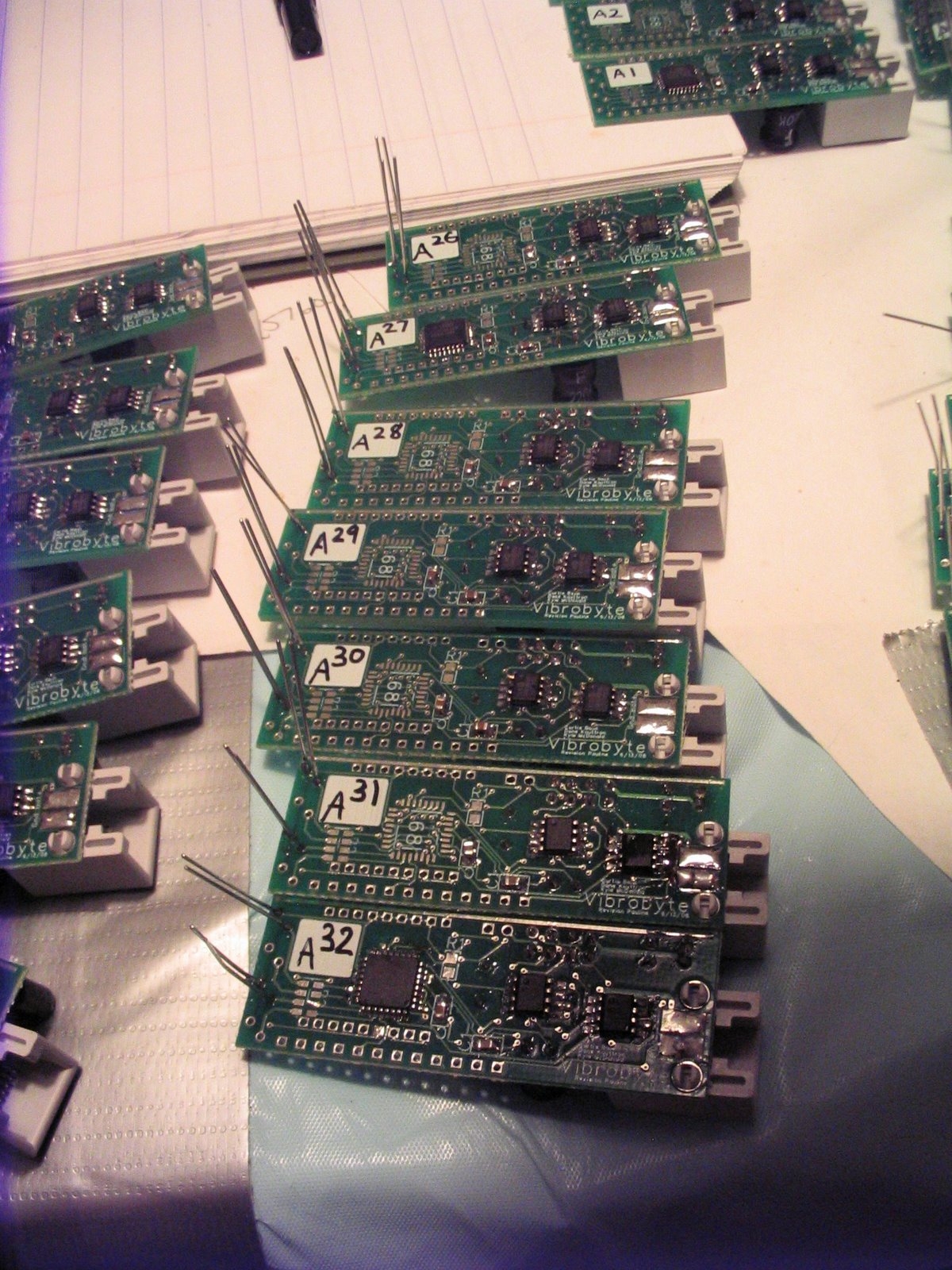
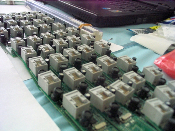
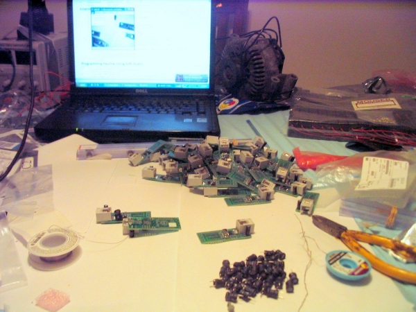
| Making
100 Vibrobytes in a Weekend |
Video |
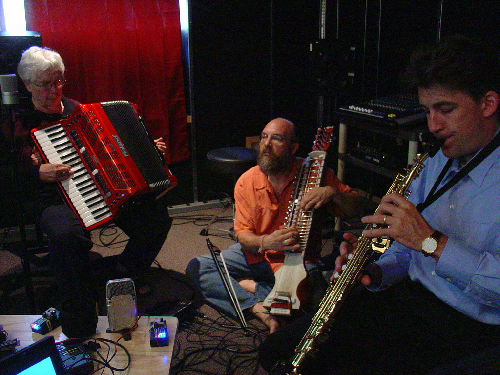
Jurrassic
5 + solder + lots of little tiny components.
|
|
| Communications
|
Image/
Media |
|
Vibrobytes
receive serial data. To make
it easier to control the vibrobytes, manipulate the control data, and
send control data over a network, there is also an OSC to serial
interpreter for Max/MSP.
All
communications are ttl rs232 based |
|
[Serial
Communication, r3]
Revision 3 breaks
the basic 3-byte packet pattern of revisions 1 and 2. Packets are
composed of anywhere from 3 to 8 bytes and are specialized for a
continuous transmission system.
Every
packet begins with a header byte followed by an address byte. Remaining
bytes are optional and specified by the header.
|
|
[Header and Address]
The header byte
takes the form 011a bcde
- a address type: 0 is single, 1 is group
- b-e packet includes output state, led state, modes,
and group state, respectively
Notice that the
header byte is the only byte to begin with a 0, distinguishing it from
all other bytes.
The address byte takes the form 1aaa aaaa, with all bits a used for an
address 0-127.
|
|
|
[Output State]
The output state is
encoded in two bytes 1wwa aass 1fff fooo
- w wave shape
- a amplitude
- s sustain
- f frequency
- o
outputs this applies to
|
|
|
[LED State]
The LED state is
encoded in two bytes 11ir rrrg 1ggg bbbb
- i ir
- r red
- g green
- b blue
|
|
|
[Modes]
Output mode and LED
mode is encoded in one byte 1111 ooll
|
|
|
[OSC Communications]
All OSC control
packets begin with /vibrobyte.
Every float should
be in the range [0, 1].
As per OSC-1.0,
i is int32, f is float32, and s is string.
/vibrobyte/output ,sisfffiii dest-type dest wave amp sus freq out1 out2 out3
/vibrobyte/output/mode ,sis dest-type dest output-mode
/vibrobyte/led ,siffff dest-type dest ir red green blue
/vibrobyte/led/mode ,sis dest-type dest led-mode
/vibrobyte/group/add ,sii dest-type dest group
/vibrobyte/group/remove ,sii dest-type dest group
/vibrobyte/group/reset ,si dest-type dest
|
|
[Glossary]
- dest-type destination type for
this message, takes the values {single, group}
- dest
- when dest-type is single,
a vibrobyte
address
- when dest-type is group,
a group number
- wave is the wave shape, takes
the value {square, saw-ascending, saw-descending, absolute-sine}
- amp is the amplitude of the wave
- sus is the sustain of the wave
- freq is the frequency of the
wave
- out1, out2
and out3 are boolean values describing which
outputs this message applies to
- output-mode takes the value
{repeat, impulse, off}
- led-mode takes the value
{battery, quality, blinkinput, blinkoutput}
- group is a group number,
(starting with group 1, group 0
is reserved for referring to all vibrobytes)
|
|
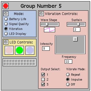
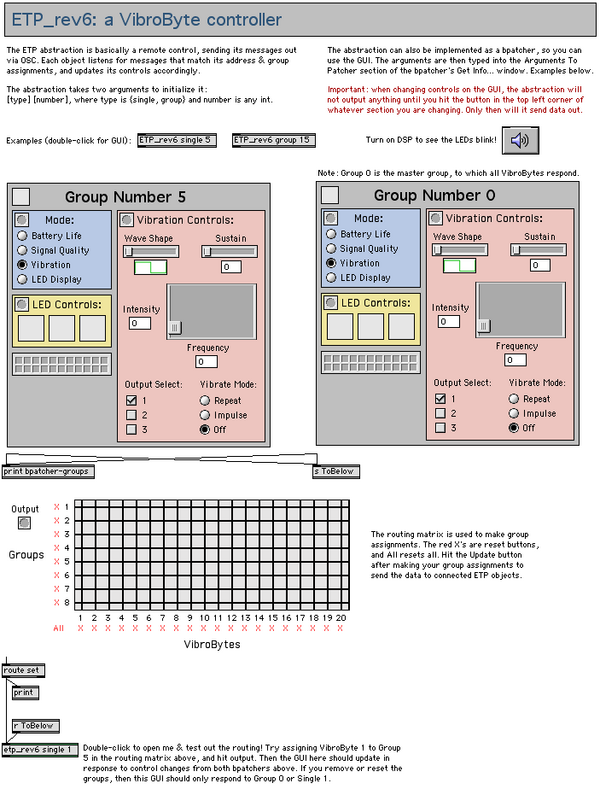
| Interface
|
Image/
Media |
The
abstraction is initialized with two arguments: the first to set its
type (group or single), the second to set its address. It can be
addressed via OSC, and can also be used as a GUI to output OSC. The
selected vibration pattern is made visible with a custom LED object.
See the help patch for more information.
To download the Max version and all dependencies in one easy package,
click here: LINK
|
 |
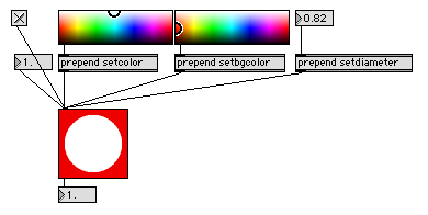
Place in jsui-library folder.
Accepts:
- floats: changes the intensity (0 is off, 1 is on)
- setcolor: changes LED color
- setbgcolor: changes background color
- setdiameter: changes the LED diameter
Outputs:
- float: the intensity of the led, can be toggled between 0 and 1 by clicking
Color and size can be specified via the jsui Inspector window
arguments field. Right-click and drag to change intensity. Hold shift
for fine adjustment.
|
 |
max v2;
#N vpatcher 627 458 1026 709;
#P window setfont "Sans Serif" 9.;
#P flonum 59 212 35 9 0. 1. 3 139 0 0 0 221 221 221 222 222 222 0 0 0;
#P window linecount 1;
#P newex 275 91 93 9109513 prepend setdiameter;
#P flonum 275 51 35 9 0. 1. 3 139 0 0 0 221 221 221 222 222 222 0 0 0;
#P toggle 16 51 15 0;
#P newex 165 91 87 9109513 prepend setbgcolor;
#P user swatch 165 51 105 32;
#P newex 59 91 77 9109513 prepend setcolor;
#P user swatch 59 51 105 32;
#P user jsui 59 141 64 64 1 0 0 etp.led.js;
#P flonum 19 91 35 9 0. 1. 3 139 0 0 0 221 221 221 222 222 222 0 0 0;
#P connect 2 0 3 0;
#P connect 0 0 1 0;
#P connect 6 0 1 0;
#P connect 8 0 1 0;
#P connect 5 0 1 0;
#P connect 3 0 1 0;
#P connect 1 0 9 0;
#P connect 4 0 5 0;
#P connect 7 0 8 0;
#P pop;
|
 |
|
|
[The Transmitter]
Attached to a
users computer, the transmitter consists of an arduino, 915mhz transmit
shield and an rf amplifier |
<code for
transmitter shield>
|
Concluding
Remarks:
Its amazing what dedicated people can produce in a short
period of time. It was a privledge working with mcdonk, scully, and
jesse French.
(be
careful, im not responsible for those soldering iron burns, or being
blinded by LOTS OF BLINKY LEDS)
Dane.Kouttron
Rensselaer Polytechnic Institute
Electrical & Electrical Power
631.978.1650