Dane.Kouttron
[2.16.19] Portable GOES Satellite Image Grabber
| There's a wonderful Github Repo [Goestools] that works alongside a software defined radio to pull some rather excellent imagery from ~22,000 miles up. I put together a 'deployable package', wrapped python around goestools and interfaced it to some buttons to make a standalone setup for 'deploy and grab' GOES-16 / GOES-17 imagery. There were some lessons learned and 'field improvements' along the way. |  |
 |
| What? |
GOES-Imagery Breakdown | Project Inspiration | Image Directory |
| Large Imagery Details | |
| So, here's a relativley synchronized image from 1600 on 3/18/2019. Its pretty interesting whats available here. Full Color The full-color image is actually a composite, of red-infared + magic. Its beautiful. The magic of making this full-color disc actually comes from the work listed here [link]. High Rate Information Transmission only sends down seven of the sixteen spectral bands that the satellite maps, these are 2, 7, 8, 9, 13, 14, and 15. Of these the only visible band we get over HRIT is band-2 (red-visible). CH2 is documented here: [pdf link] and CH13 is documented here: [pdf link]. CH13 is basically a 'here is a rough temperature of the earth' infared snapshot. Gluing together Band-2 and Band 13 we can make a pretty color rendition. This is done by using a color LookUp Table (LUT), which is straight up amazing. again, this is documented here: [link]. I did not put these images in a particular order, photoshop barely survived putting 5 of them in a composite image. CH 2 and CH 13. BAND-15 Band 15 is ~12.3 uM, and is nominally the longwave infared "dirty" band. This is used to estimate low-level moisture, volcanic ash, airborne dist / sand, and to an extent, sea-surface temperature. This is nominally 11.8 -> 12.8 uM. There is an overview of the BAND-15 listed here [pdf link] BAND-9 Band 9 is the 6.9 uM band. which is a mid-tropo water vapor band. This is used for mid and upper-level water vapor tracking, jet stream identification, hurricane forcasting, storm forcasting, severe weather, jet stream things. There is an overview of the BAND-9 listed here [pdf link] BAND-8 Band 8 is the 5.8 to 6.6 uM band. This is the “water vapor” band, used for upper-level tropospheric water vapor tracking. This can be used to do jet stream identification and evenhurricane track forecasting. There is an overview of the BAND-8 listed here [pdf link] BAND-14 Band 14 is the 10.8 to 11.6 uM band The longwave infrared band is nominally used for general weather forecasting, analysis, and broadcasting applications. This provides feedback on atmospheric processes associated with cyclones and also in single thunderstorms and convective complexes. This band also allows for precipitation estimates, cloud-drift winds, hurricane intensity and track analyses, cloud-top heights, and volcanic ash detection. see more here: There is an overview of the BAND-14 listed here [pdf link] |  |
| Humble Beginings |
||
| So
there were these free wifi dishes... D-LAB had recycled a few of these wifi-dishes, they are all nominally the '24db ish things' [link] where a fairly solid N-Type connector passes up to a horn and reflector. These are somewhere between $40-100 each, portable and fairly excellent. Each antenna consists of two halves which, when stacked hide away reasonably well. Shown is a 'gifted one' hiding on my shelf in MITERS. The dishes themselves did not have an RF horn / reciever, so those needed to be purchased seperatley. |
 |
 |
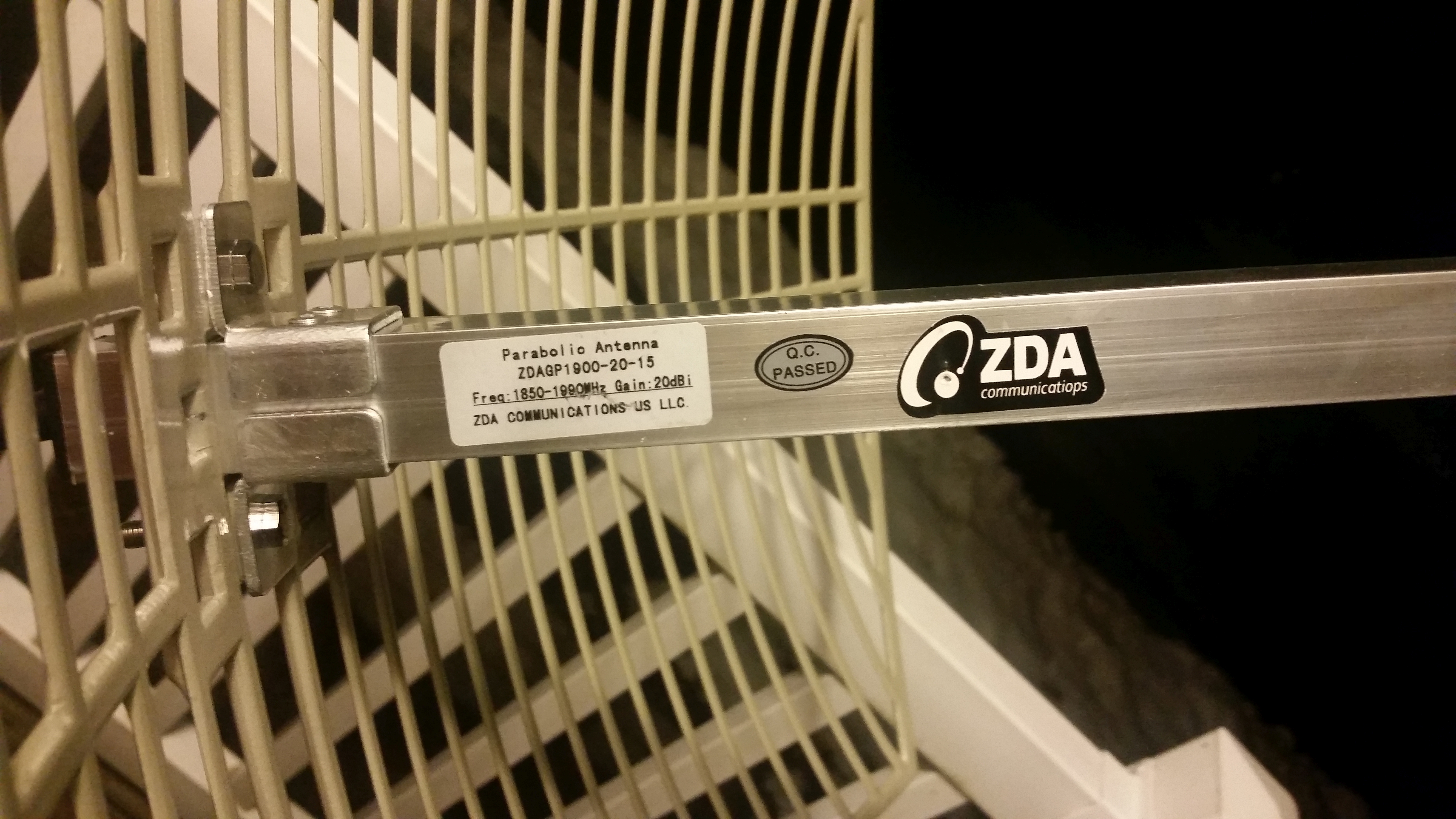
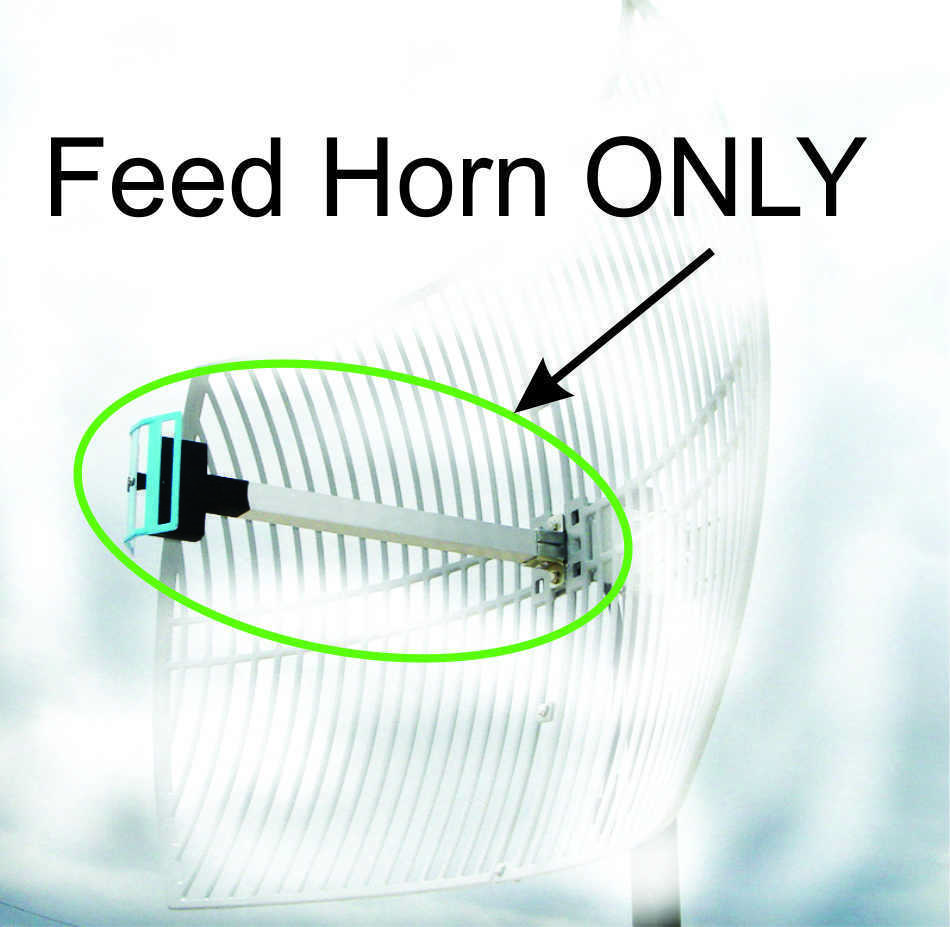
| Finding some 'Horns' "Horns"? The middle reciever bit of the dish is labeled as a horn, where realistically its a small dipole in a plastic shroud. It's assembled in two parts, the bit that attaches to the dish, with the long extruded shaft, and then the reflector that bounces the incident rf onto the main aintenna. I was able to find just the middle on ebay. The 'horn' I found was actually for 1850-1990 mHz, which is a little outside the band I was looking for, but 'close enough'. There are also 2.4ghz versions, which can be length-adjusted to work at ~1700mhz. |
 |
 |
| Some
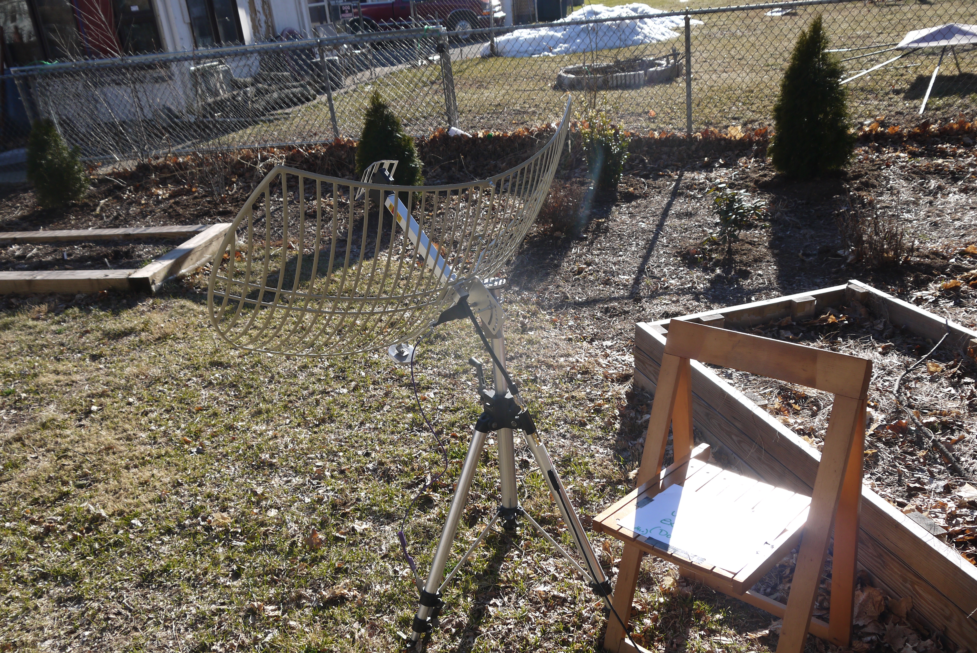
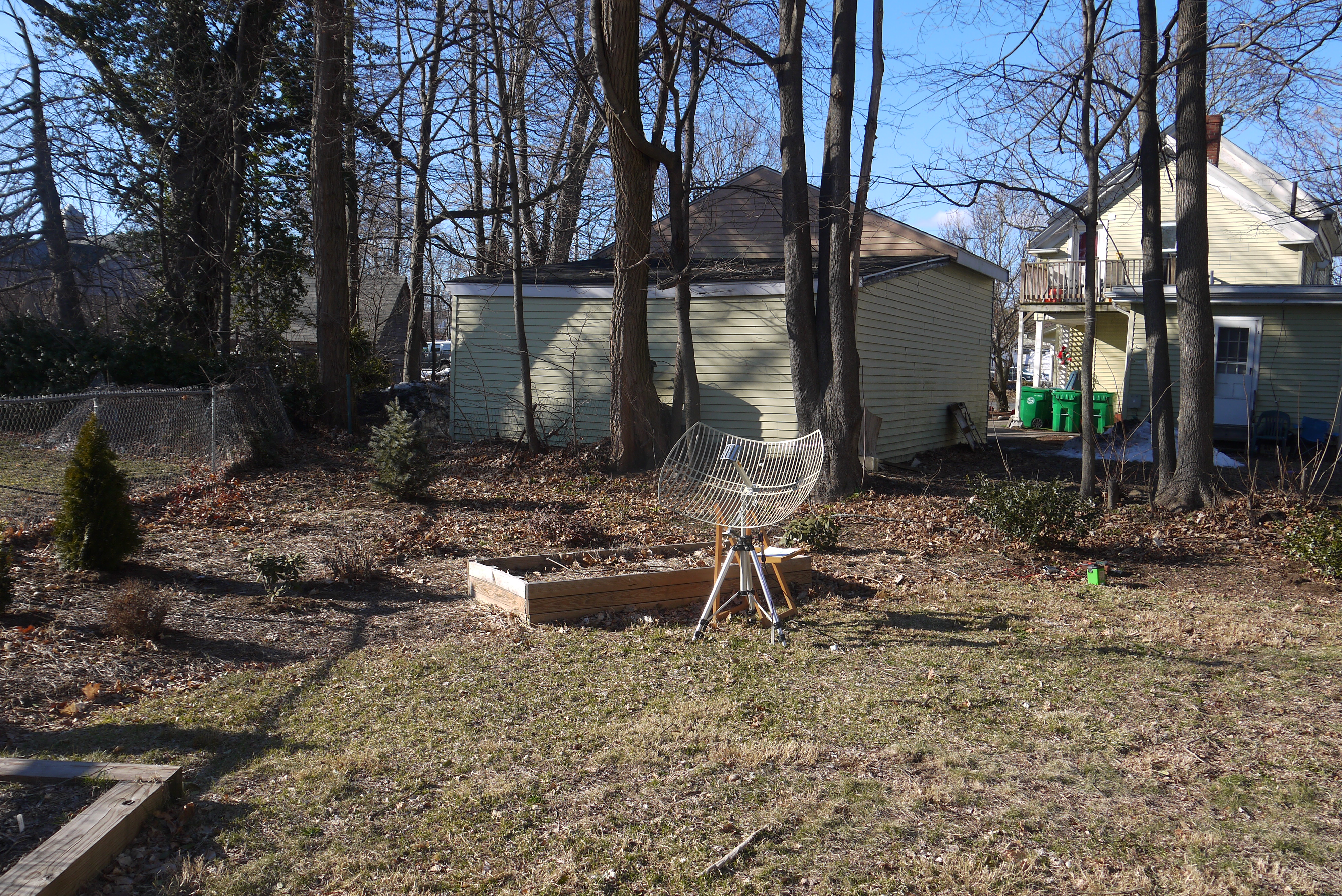
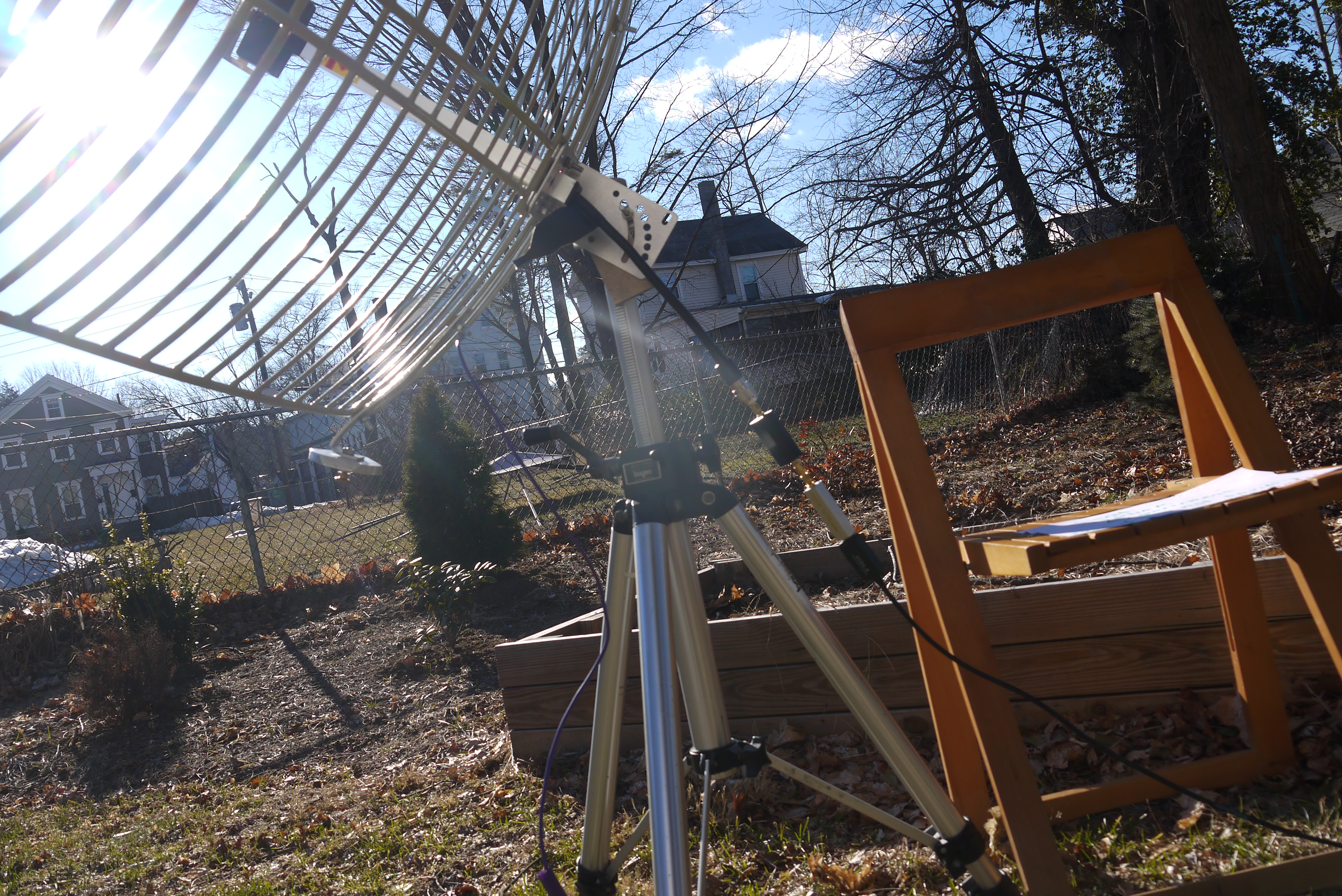
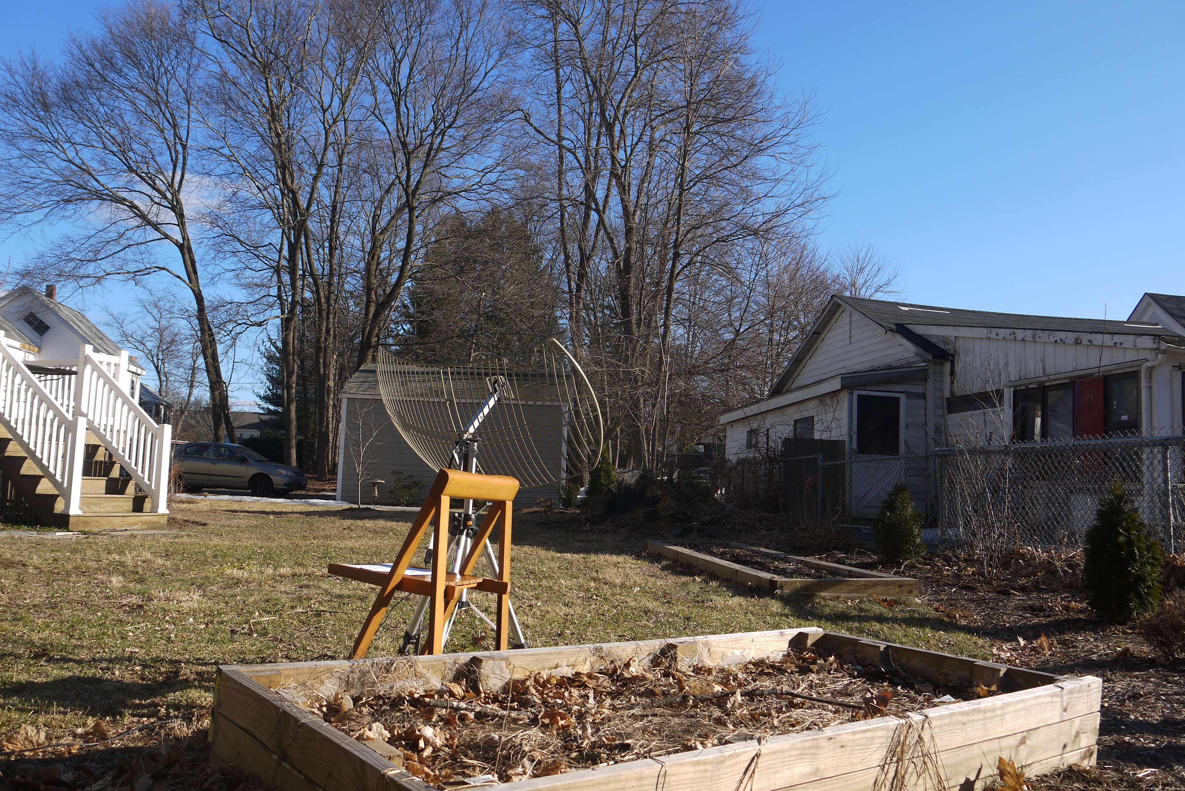
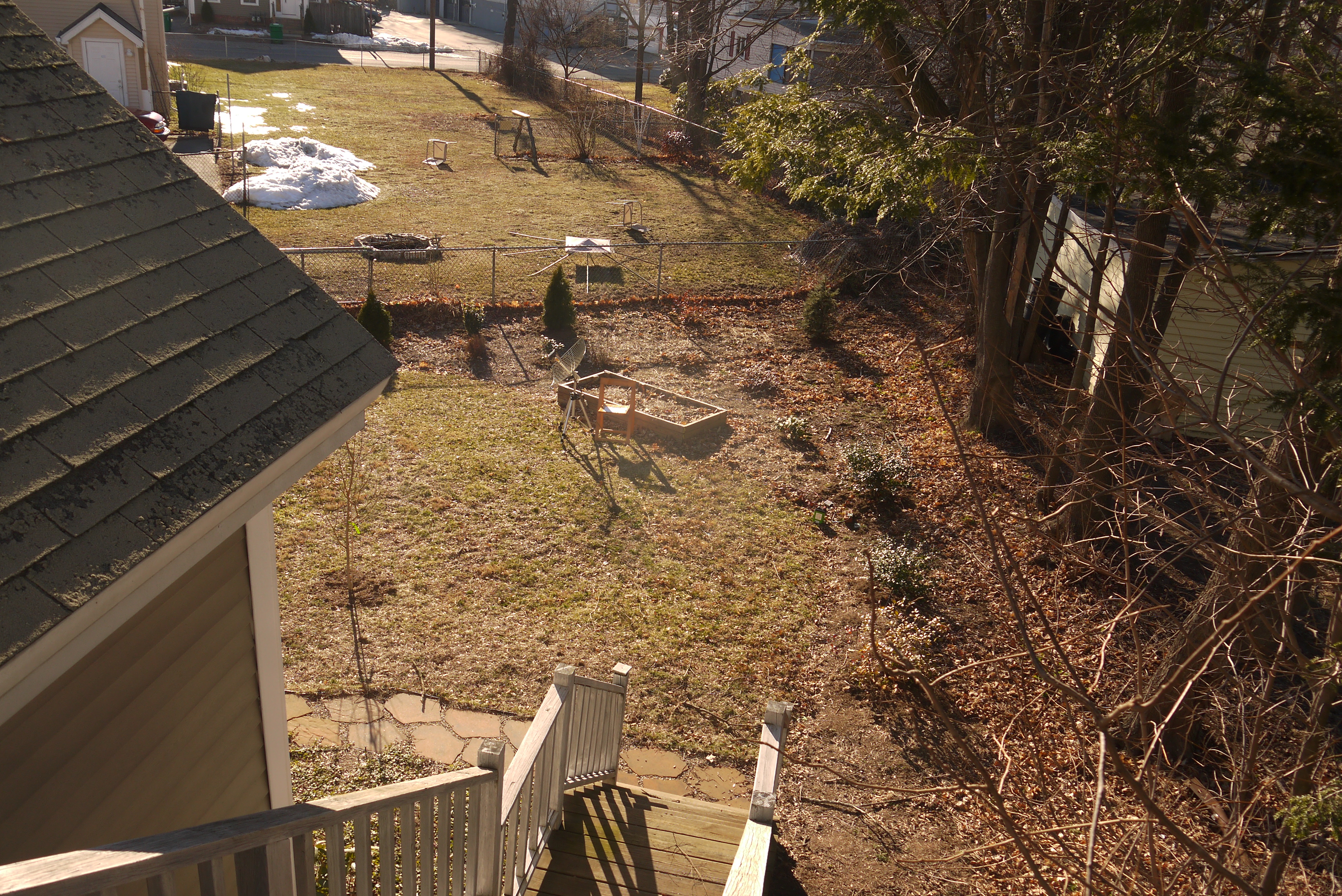
first-order testing: Hardware required to pull down imagry from GOES-16 / GOES-17 are five things: A powersupply/battery, small single board computer, an SDR, a amplifier+notch filter and a ~+20 db dish antenna. I used a camera tripod for initial testing. Shown are some photos of the setup in my backyard. You will probably also need a chair as finding the satellite can be incredibly time consuming. |
 |
 |
| Initial
testing continued... As this was spur of the moment testing (free time is best put to use when it appears), my setup was a bit crude. A 12v LiFePO4 battery feeds a variable input 5v dc/dc power supply. This feeds the single board computer, which also powers the software defined radio, via USB. Later on an access point was used to act as a wifi client and connect the single board computer over to a home network, or just act as an access point. |
 |
 |
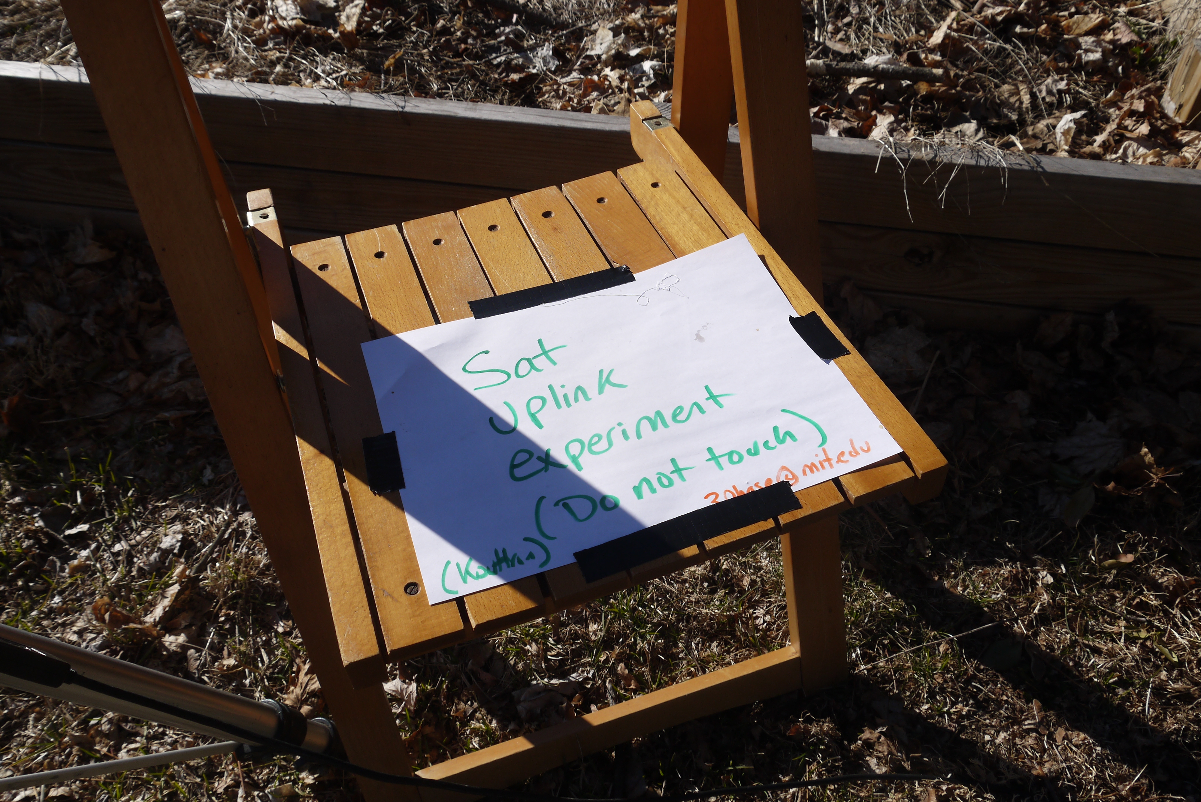
| I
was after a timelapse / day's worth of imagery, so I left my 'haistily
assembled' imaging setup in the back yard with a small note. I put a
small tupperware over the electronics and pulled data all day. There
were some rough spots, a 'stout' collapsable camera tripod is still
barely rated for holding 5 lbs of gear, while this dish had alot of
wind shear surface area, if the wind was just right it would wiggle a
bit resulting in poor aiming and a loss of data. |
 |
 |
| Some
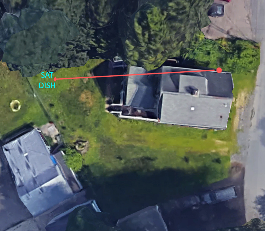
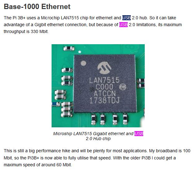
issues in Raspberry Land For a first pass, this was great. The raspberry pi 3b+ was pulling down images. I had it connected (weakly) over its onboard wifi, and I could pull images out of the air! For the first setup a long USB cable went from the SDR to the raspberry PI 3B+. This kept the WIFI module away from the more sensitive reciever and everything worked fairly well. Due to the physical location of the setup and my home access point, I was stuck with ~100kb/s ssh file transfers, which, is a bit slow. I opted for ethernet, as, it seemed like a good logical progression. This is where I ran into comical issues. It wasnt terribly easy relocating the AP closer, but running a long ethernet cord is simple right? RIGHT? |
 |
 |
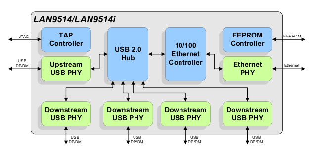
| Did you know? The raspberry Pi 3B+ ethernet controller is actually a USB device? I did not. After switching over to a long ethernet cable, i found that whenever I did a file transfer or used the ethernet even lightly, the SDR dropped packets all over the place. At first this was incredibly confusing. I checked HTOP, and while CPU usage was high it wasnt pegged at 100%. I checked shielding around the ethernet cable (maybe data transfer was radiating and causing interference?) After some copper tape and futzing, no, that was not it either. Lo and behold, if you have to juggle 2 USB devices, and one's rather time sensitive, you loose packets. Some more details here: [link]. Ethernet traffic and file transfers putzed up getting pretty photos from space. |
 |
 |
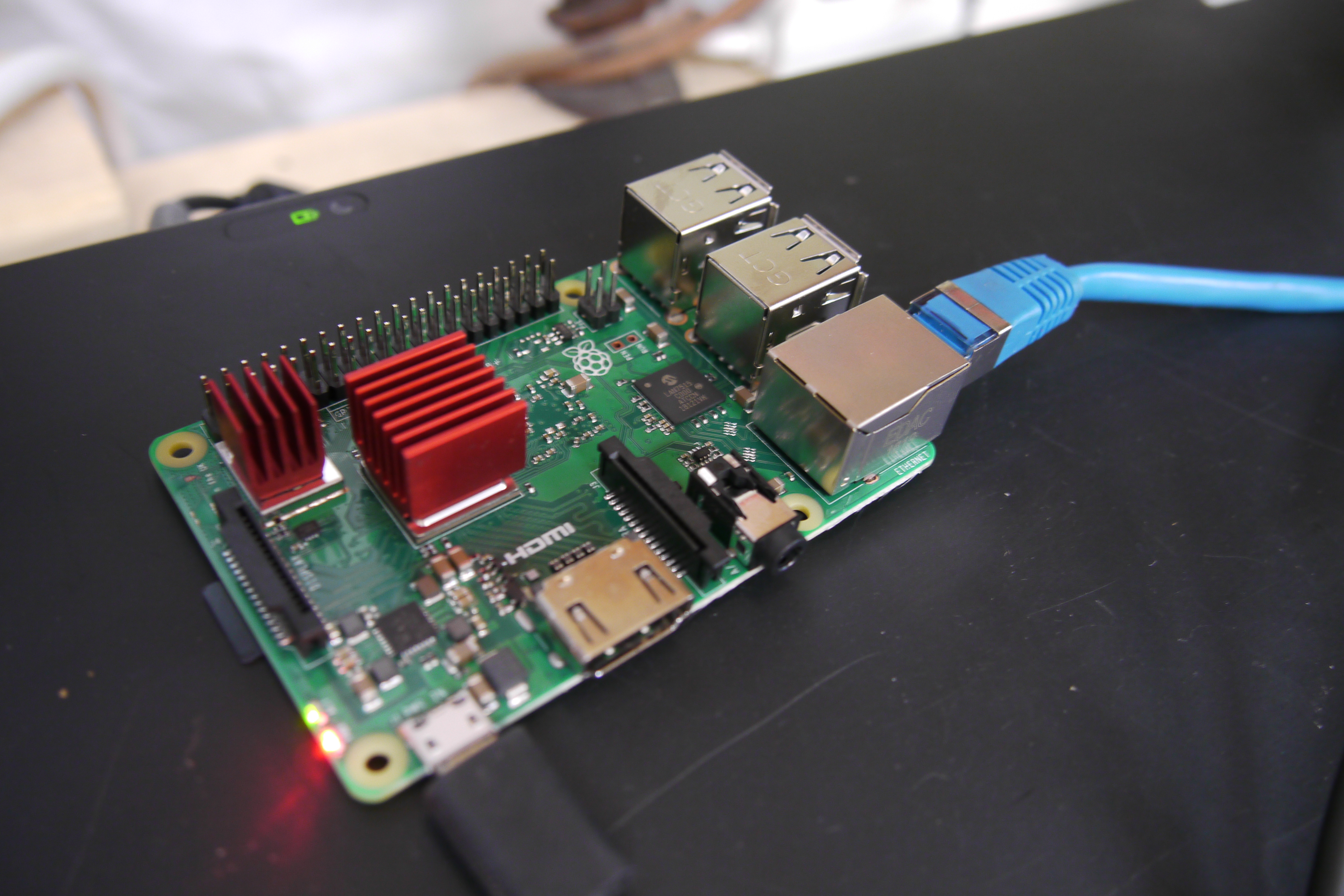
| And
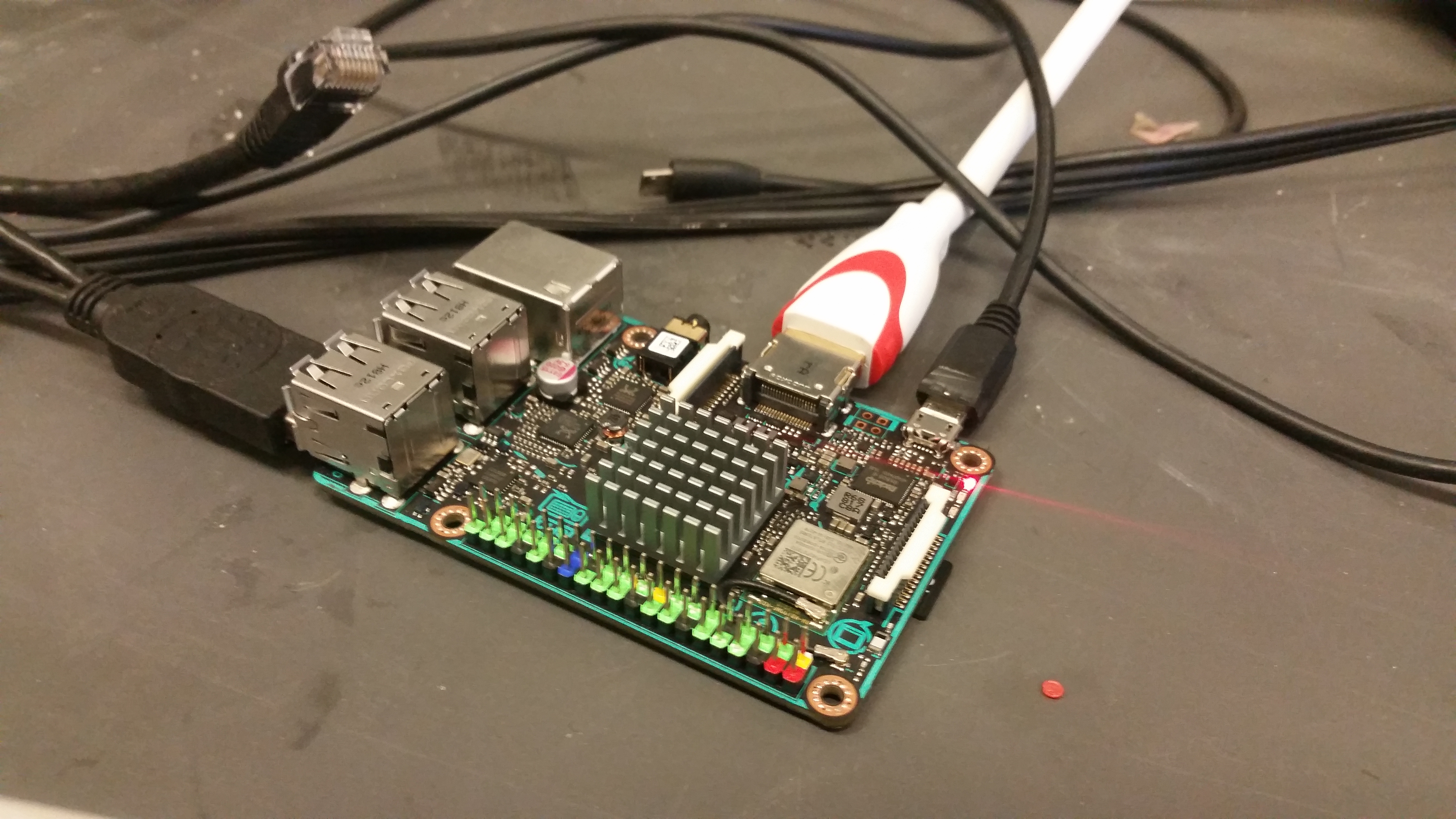
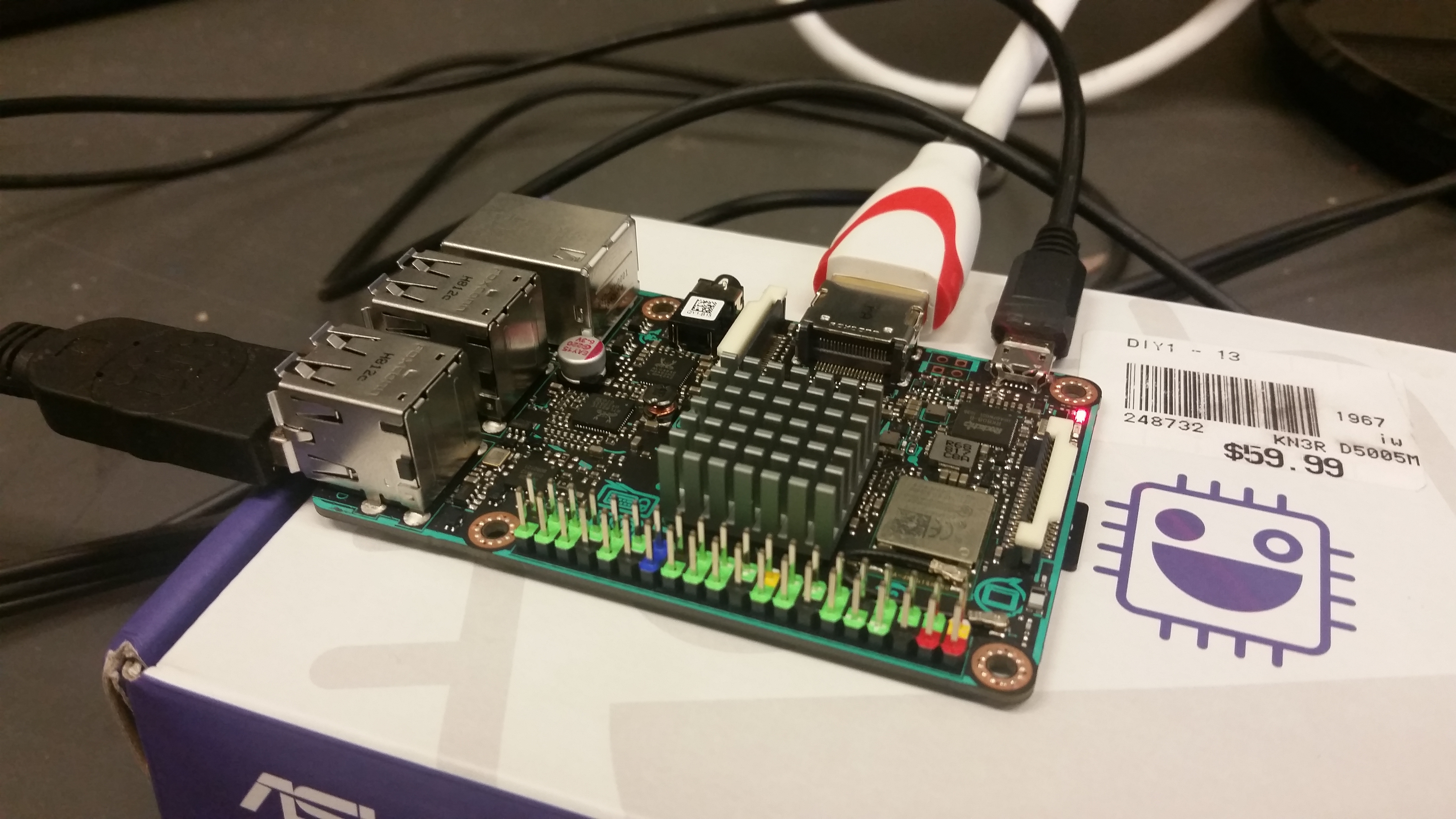
then there was Tinkerboard The Ethernet thing really bugged me, I want my data and my images too. I found the ASUS tinkerboard after doing some digging and its actually really interesting. About 3x the cpu HP vs the raspi-3B+ and a dedicated ethernet phy. It was a bit more pricey, at 2x the cost at the local microcenter (i didnt even need to wait for amazon, cambridge microcenter is a 15 minute walk from MIT). Fantastic. The ASUS tinkerboard is a raspberry-pi like board, with a few extra functions. The issue I was having with the ethernet controller on the raspberry pi being shared with the same USB bus as the SDR traffic, went away. The only reported issue was its power consumption, which, generally the micro-usb connector is too small for. I fed in power via the GPIO and everything was fine. This is a little dicey, as piping in 5v directly looses alot os the micro usb power protection hardware. |
 |
 |
| Did I mention how much I love this ecosystem of small single board
computers thats available now. Here's a side-by-side of the Ras Pi 3B+ (left) next to the tinkerboard (right), almost identical form factor, with extra hp. |
 |
|
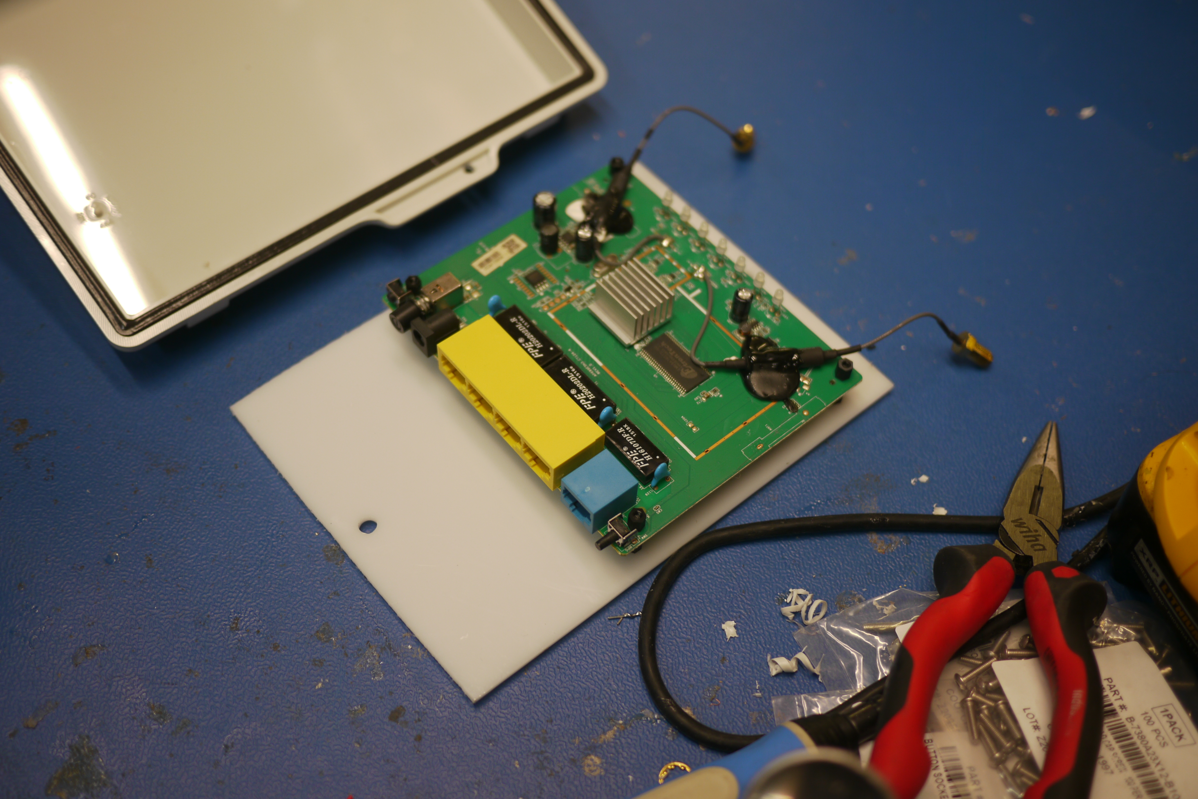
| With the data transfer issue no longer a problem, I looked at re-purposing an older access point. | ||
 |
||

| SOFTWARE TIME! |
||
| Time
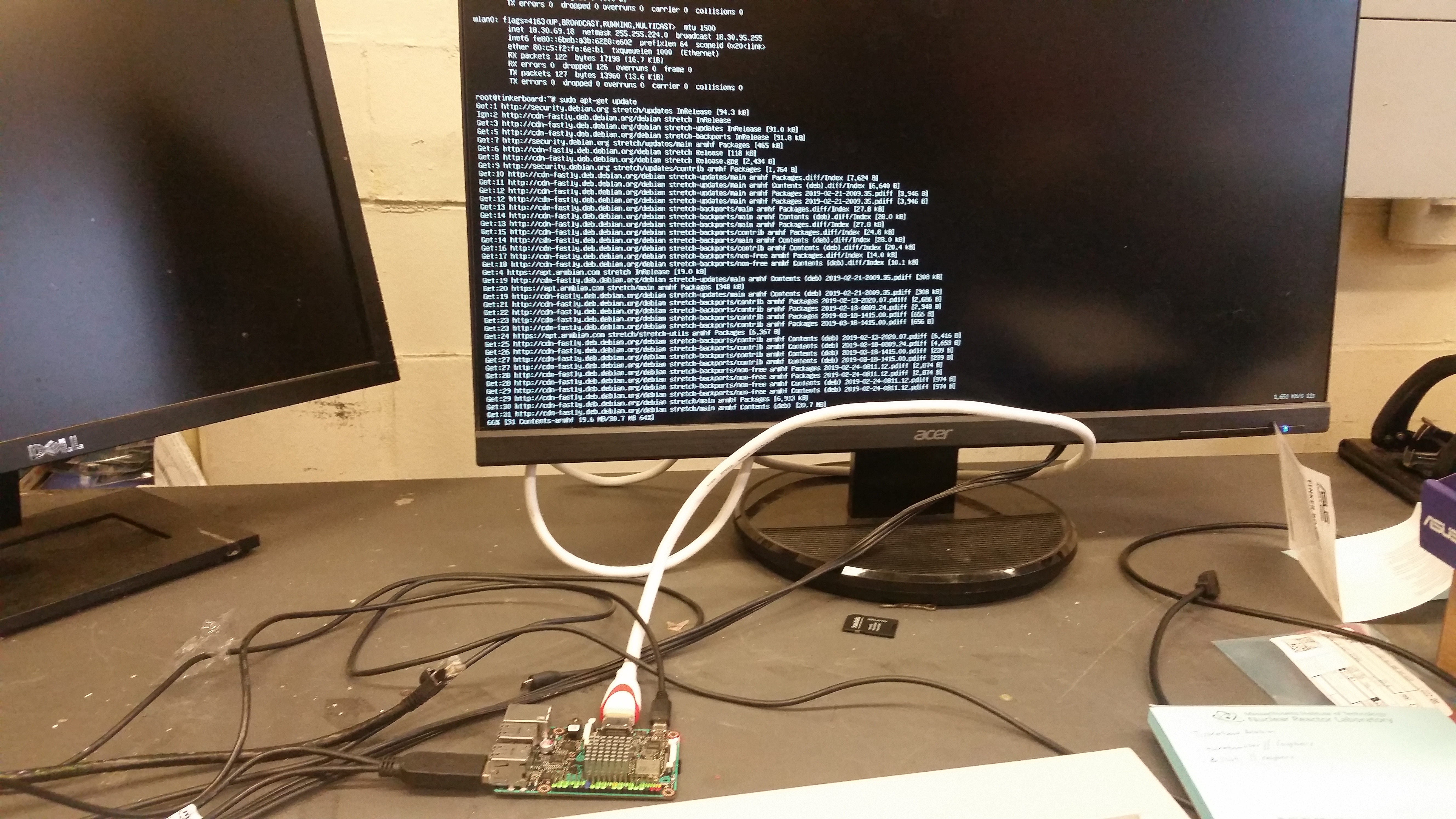
to install on the ASUS tinkerboard The software install was performed with an HDMI display connected and the tinkerboard powered over micro-usb. The board sat on its box for isolation. At this point, I wasnt sure if the goestools package would have an issue with the tinkerboard cpu, so it didnt make sense to mount everything at that point. The installation of GOESTOOLS is also outlined here [link] for the sake of documenting exactly what i did, my process is listed below. |
|
 |
| After a quick install of Debian for the tinkerboard [link] I performed updates. Installation and OS update can take a while and require a reasonable connection. Next up restart the system so we're starting fresh. This forces a restart after 1 minute. Starting from a working OS install and a happy live network connection we're going to continue from here with the complete software install, step by step. |
 |
|
| Lets get HTOP installed, which can be useful later to visualize CPU usage and ram usage | 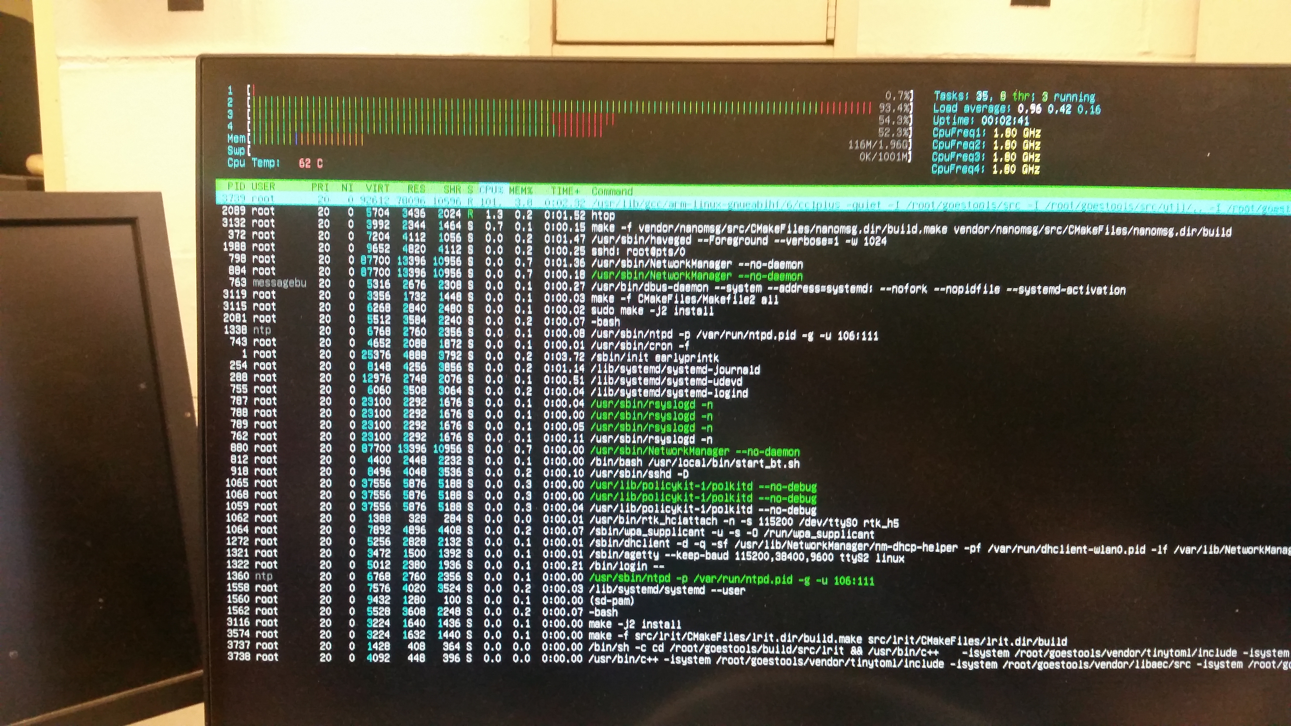 | |
| Next up, install associated dependencies for goestools | ||
| Begin installation of librtlsdr | ||
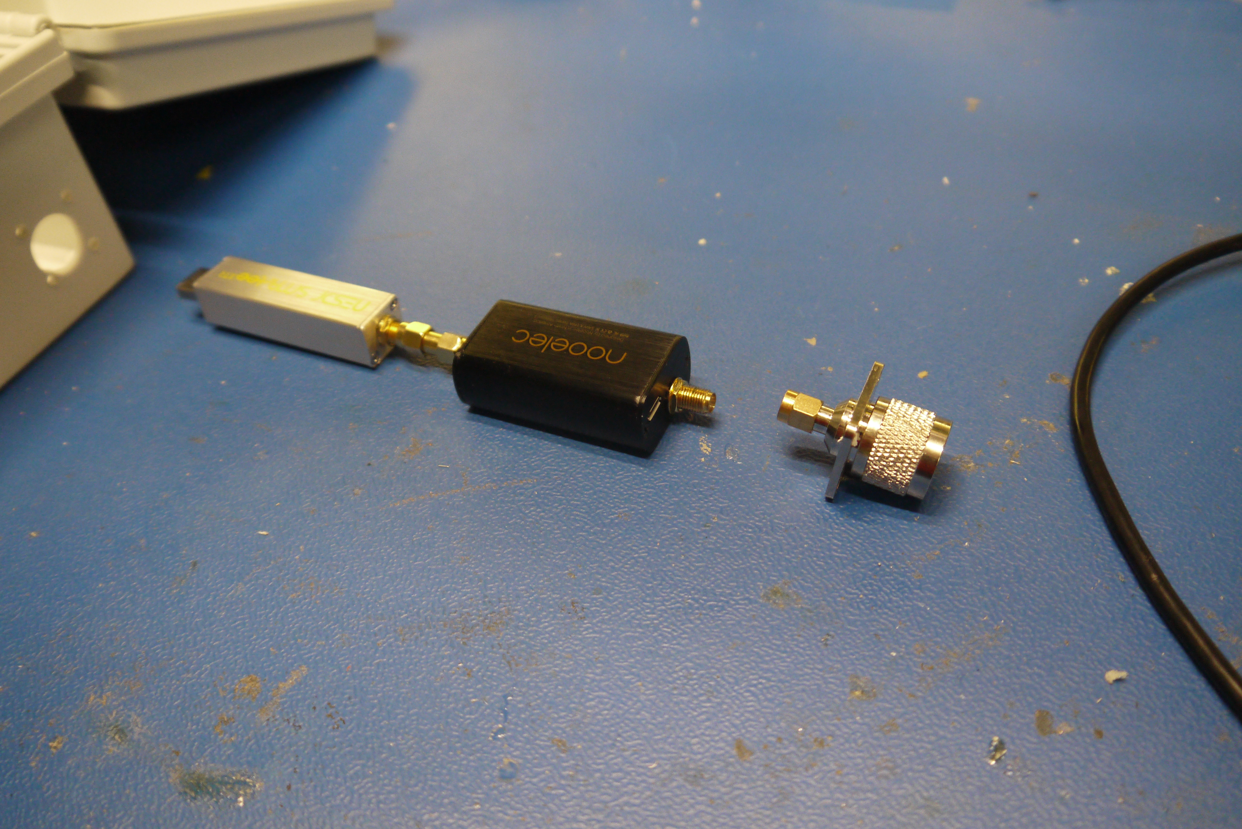
| At
this point the SDR should be a functional device, its important to note
that you should never run an SDR without an antenna connected, it opens
the SDR up for ESD failures, etc. Now's a good time to plug in an SDR
with even a dorky rubber ducky antenna. For this i'm using the nooelec
sdr [amazon link] next up make sure that the rtl does the SDR thing Finally exit out of rtl_test with a ctrl-c command. If you're using the same hardware you should be fine and things are running along. | ||
| Time to install GOESTOOLS | ||
| Time to make a config file, we're almost there! What does this config file do? GOESTOOLS reads this config file on startup to determine the frequency it's listening in on. Sample rate and gain is a bit of a game. I've found its partially single-board computer horse-power dependant. It was odd, same SDR and notch filter had different preferences on sample rate & gain, vsersus best case viterbi error rates. | ||
 |
 |
| Battery
Module |
||
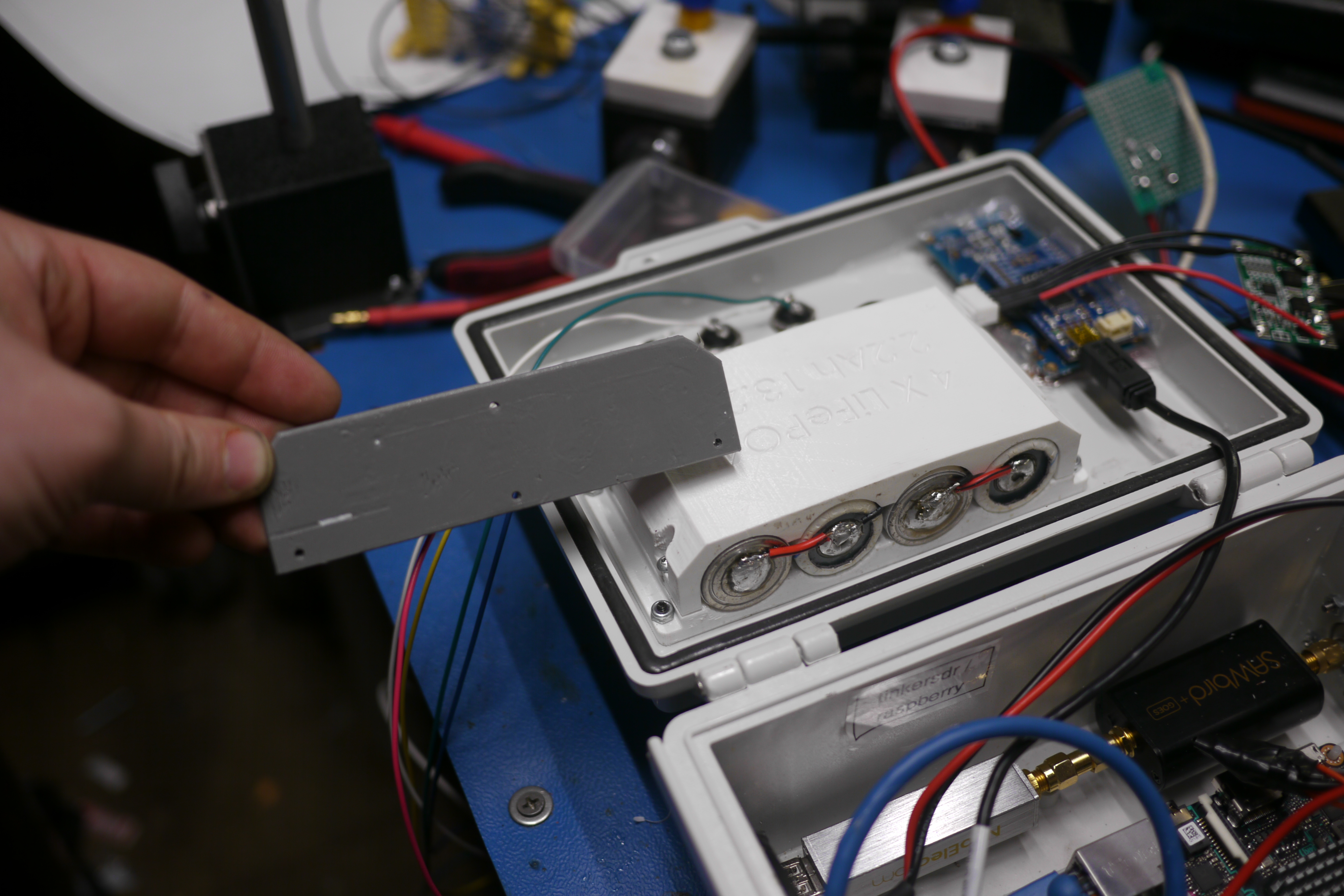
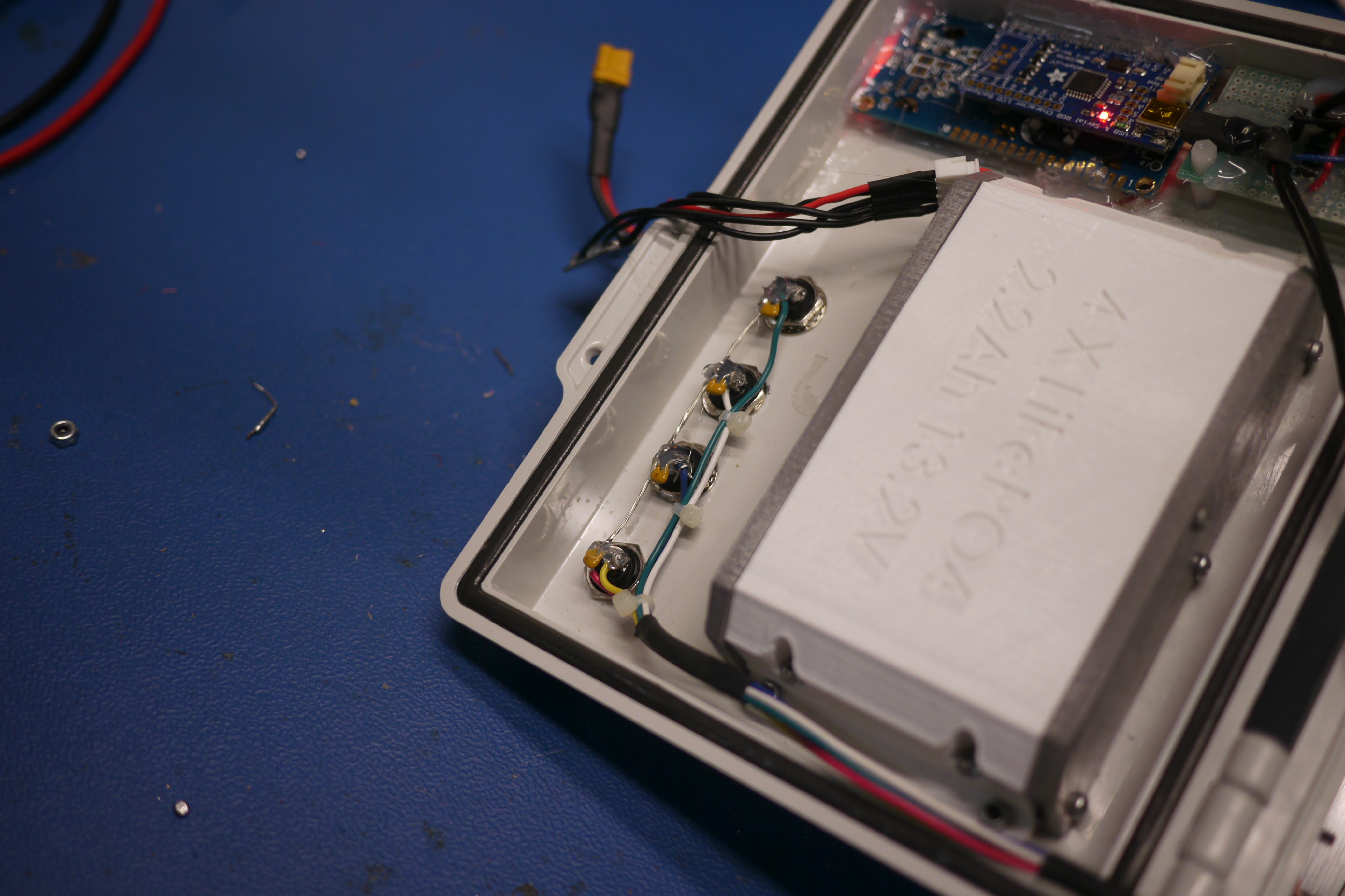
| A bit of the hardware in this enclosure is unnecessary, an internal battery is not really a requirement, but it makes a difference during setup and deploy. The goal was to set this up and have it run on a larger battery pack, but also be able to disconnect the larger battery pack to swap batteries or whatnot. As such I opted for a relativley small pack, 4S1P LiFe 2.2Ah cells. Lithium Iron Phosphate is a wonderful chemistry, four seires cells matches up well with standard automotive '12v' things, its fairly excellent at low temperature and high temperature performance. Also i had a couple dozen of them on hand convieniently. For first-pass this was just 4-cells in series, later i added balance and protection circuitry. | 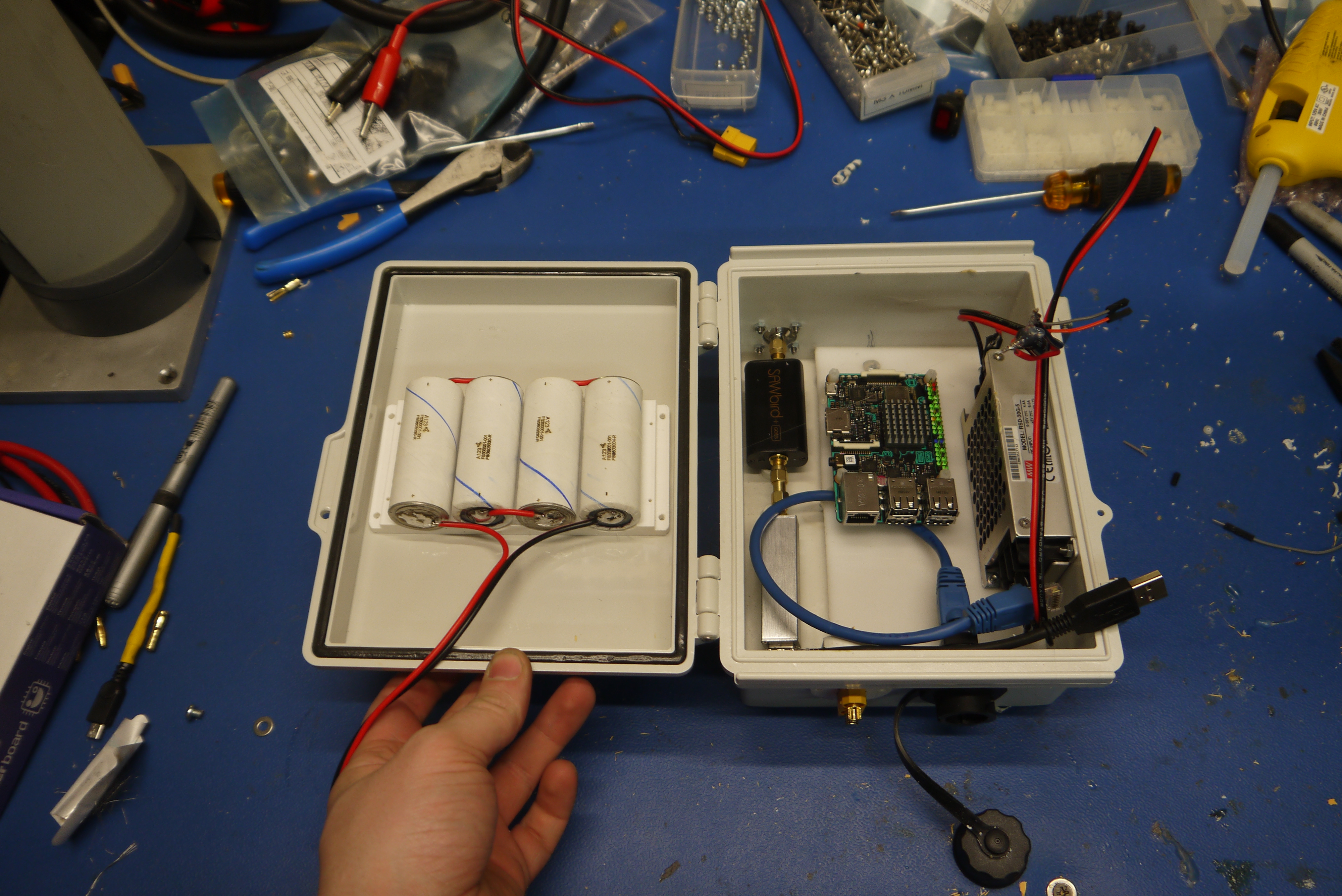 |
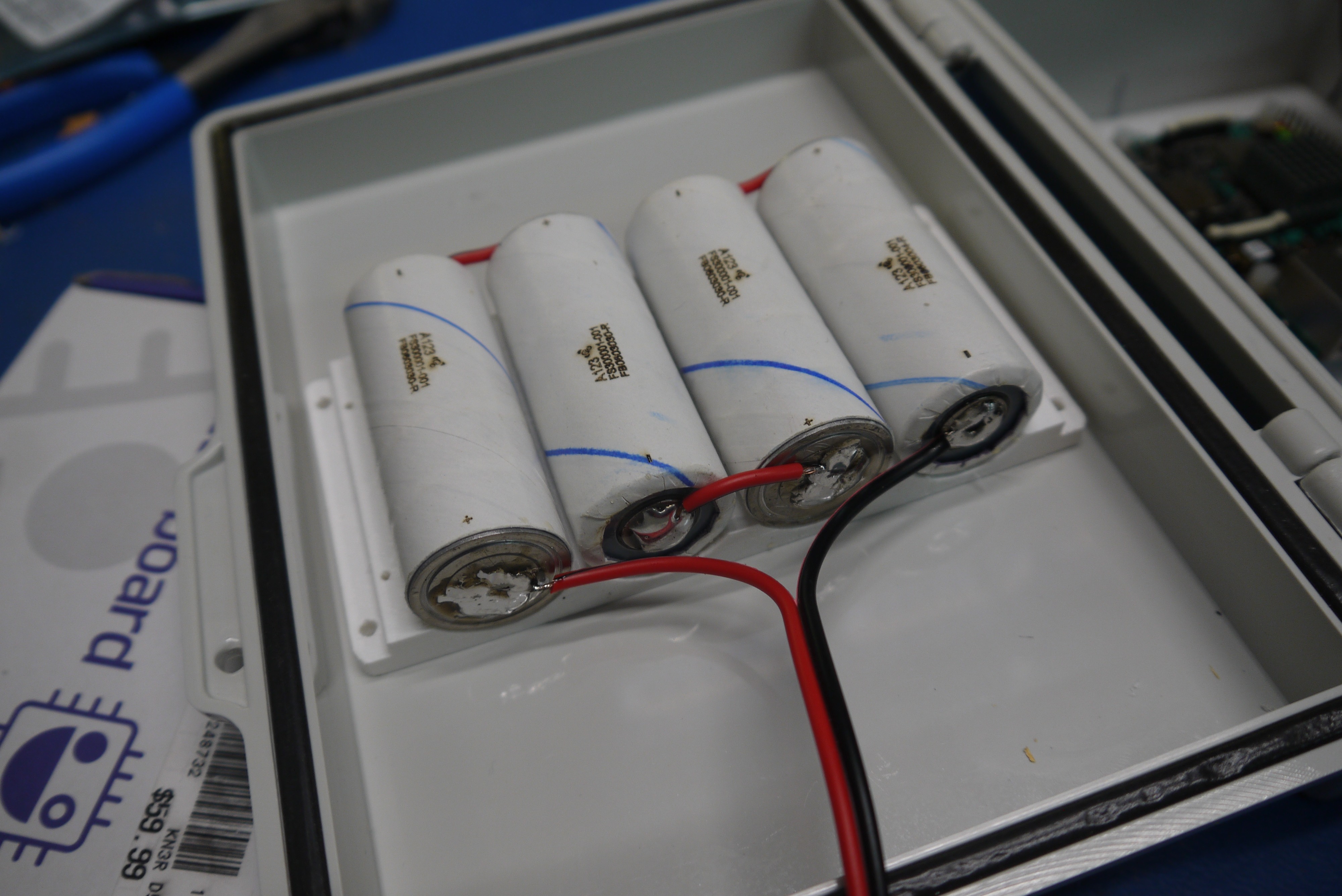 |
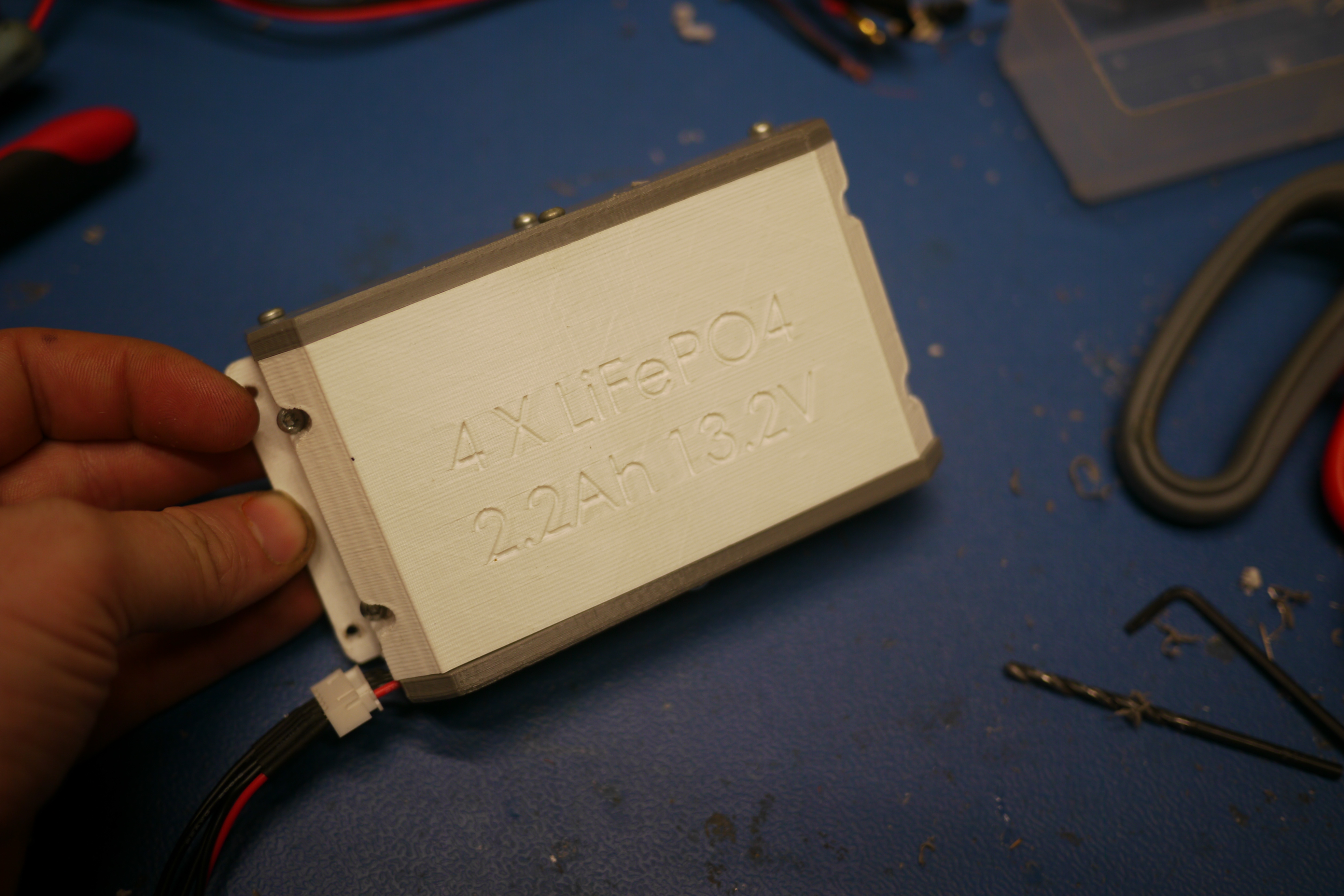
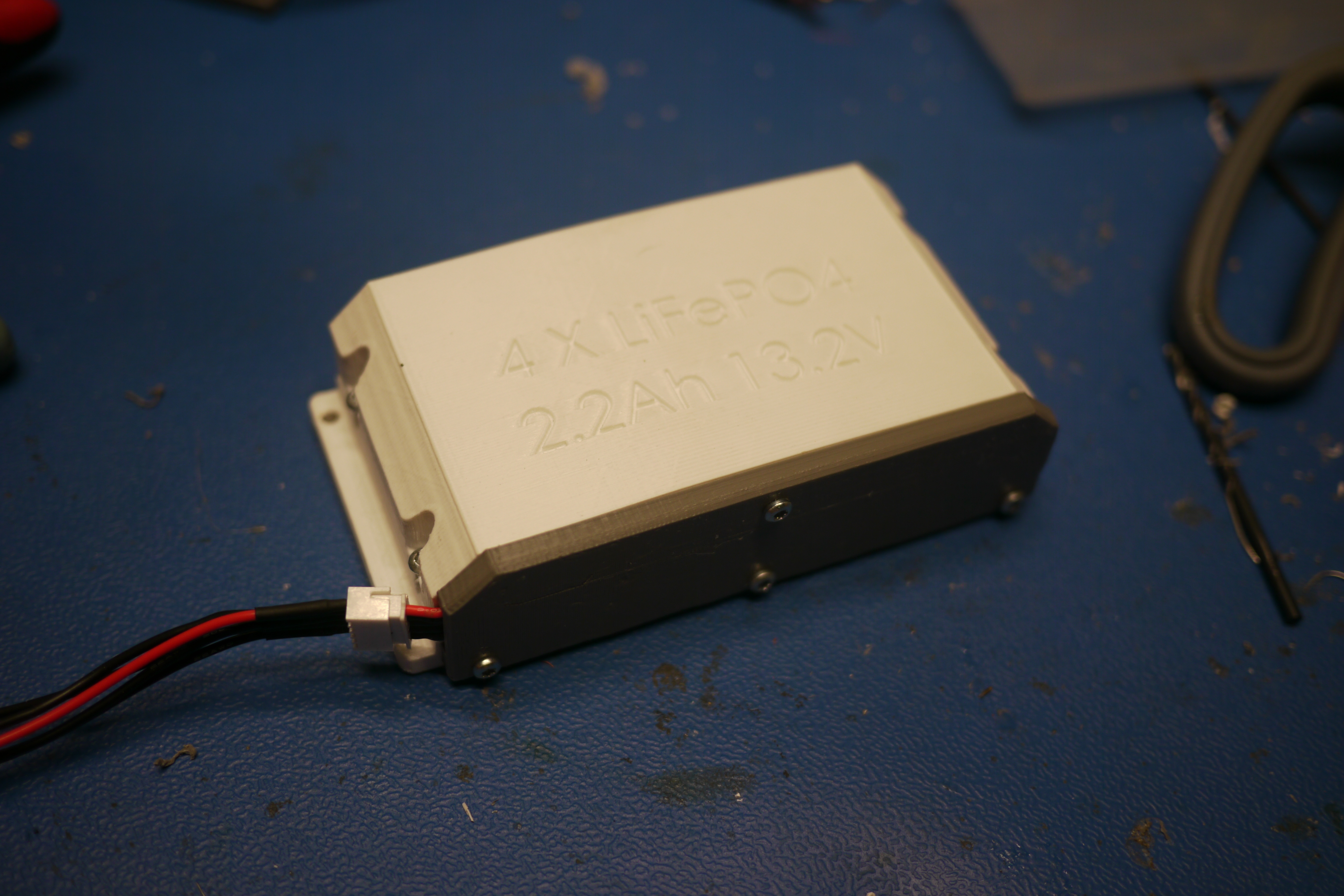
| Fast forward a bit, the printer cranked away at making a case for the cells, mostly to prevent anything from being exposed / having other things bump into the batery module. A 5 pin JST-xh connector was added to act as a balancing connector. As the power consumption for this whole thing was <10w, i opted to just use the balance lead as the main battery connector. |  |
 |
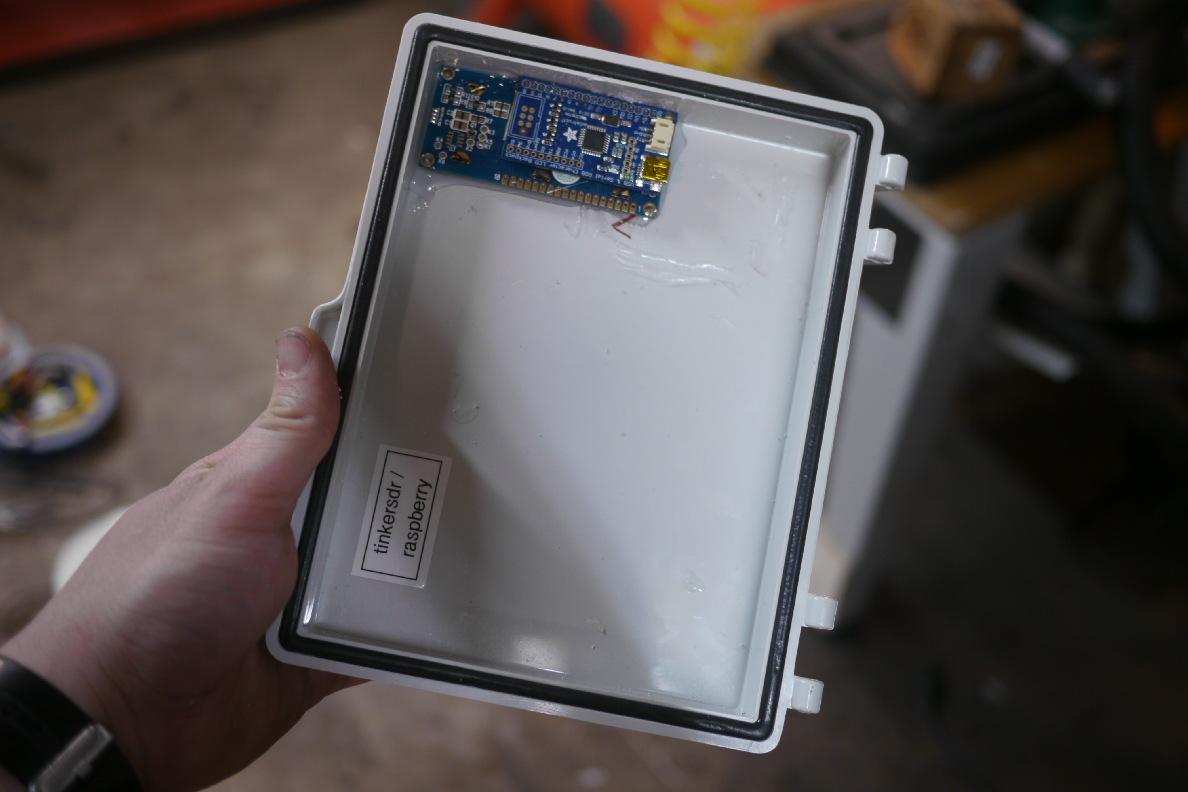
| Plastite
screws hold the cover and end-cap in place. The completed subassembly came out cute, i left the labeling indented to fill with acrylic paint such that it stuck in place as labeling, but, i opted not to that particular evening. Its still on the list of things to do. |
 |
 |
| Putting the whole thing together |
||
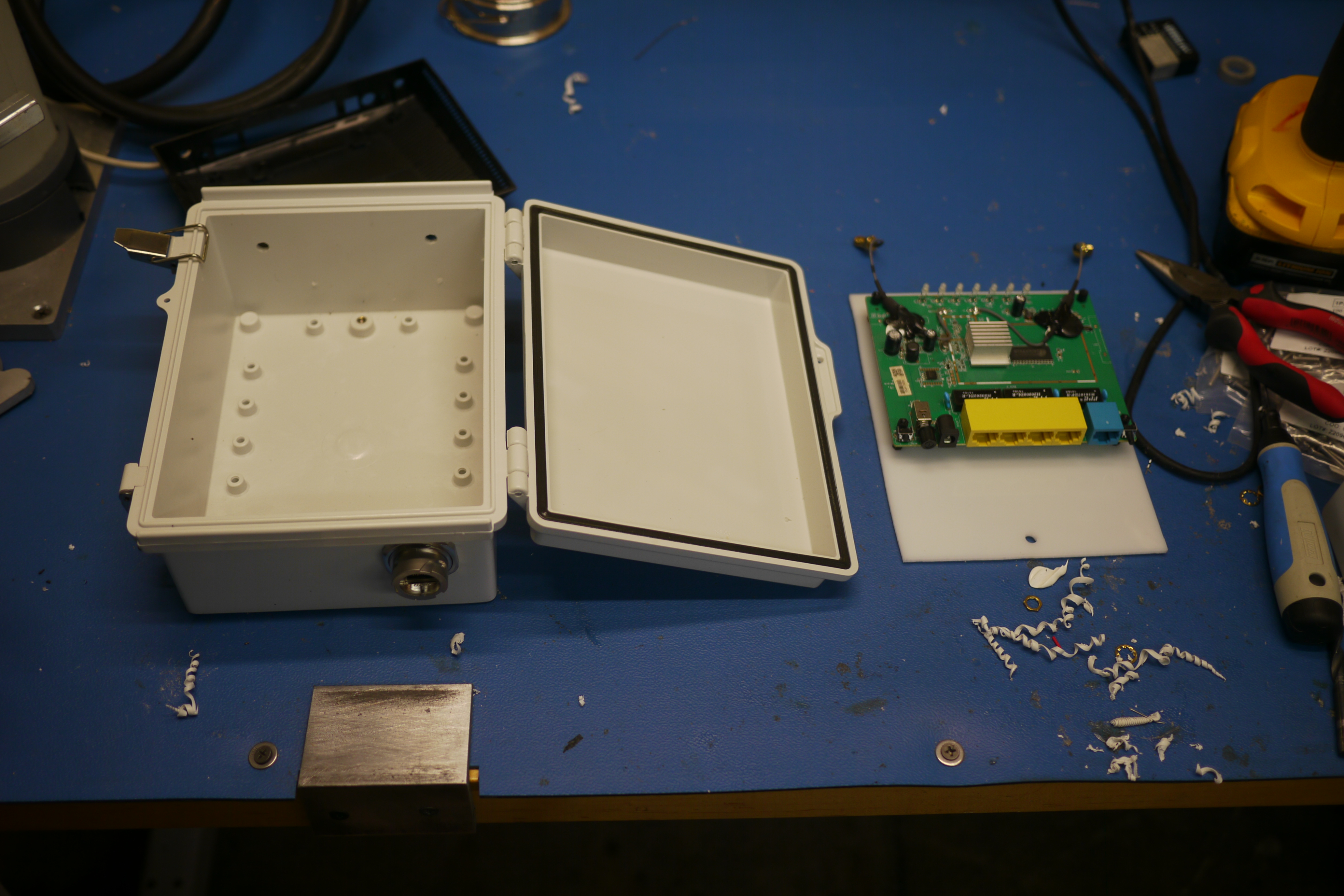
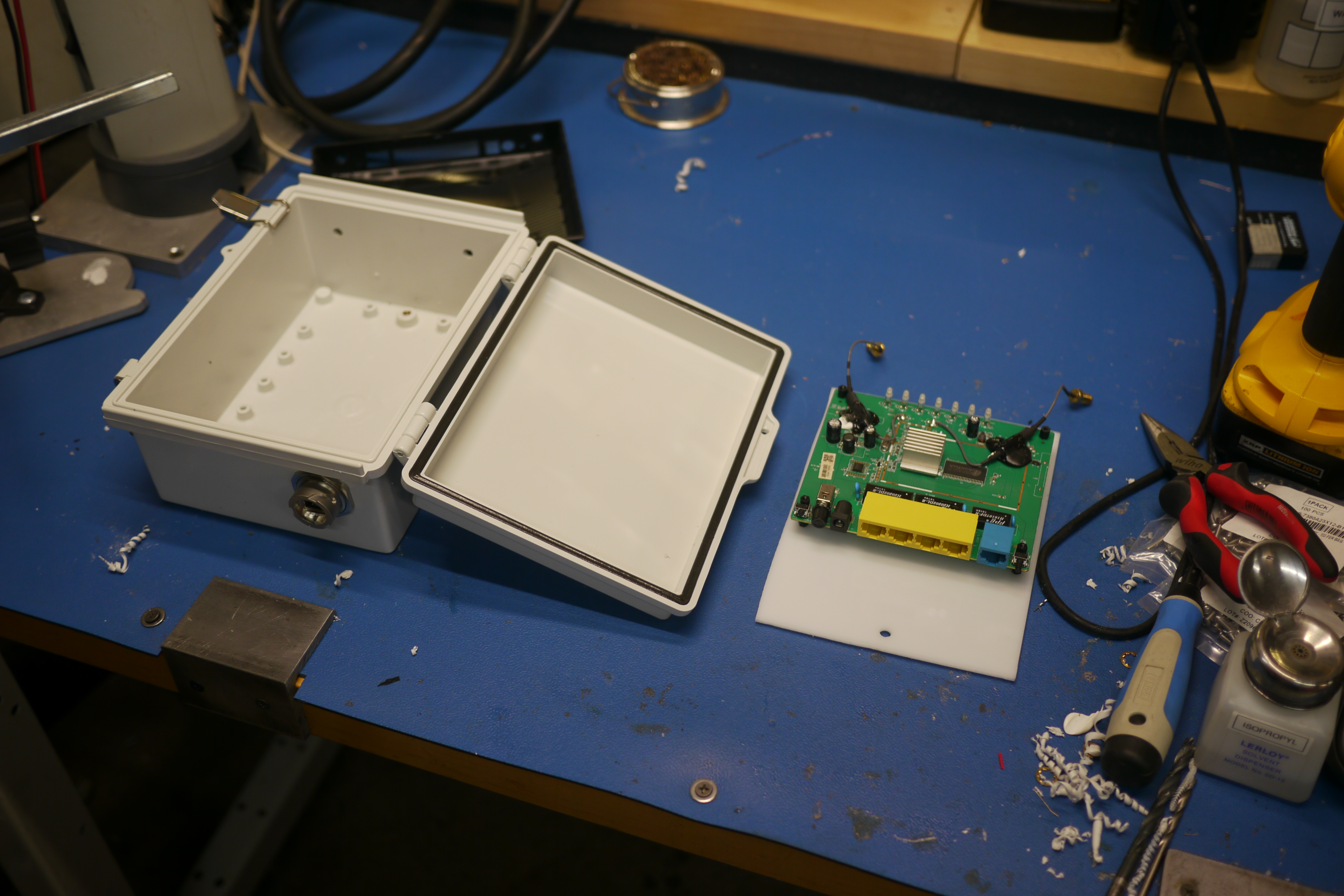
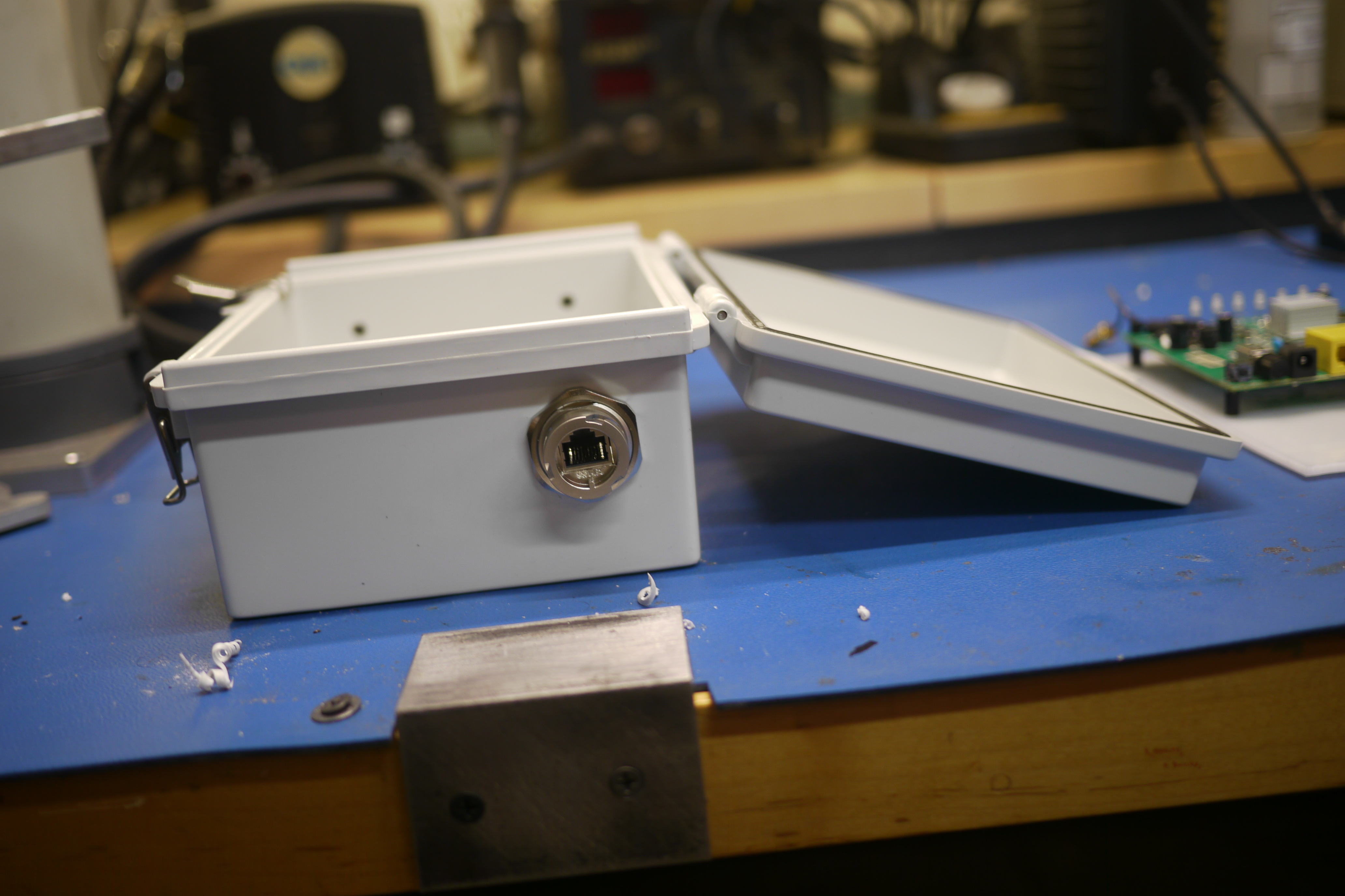
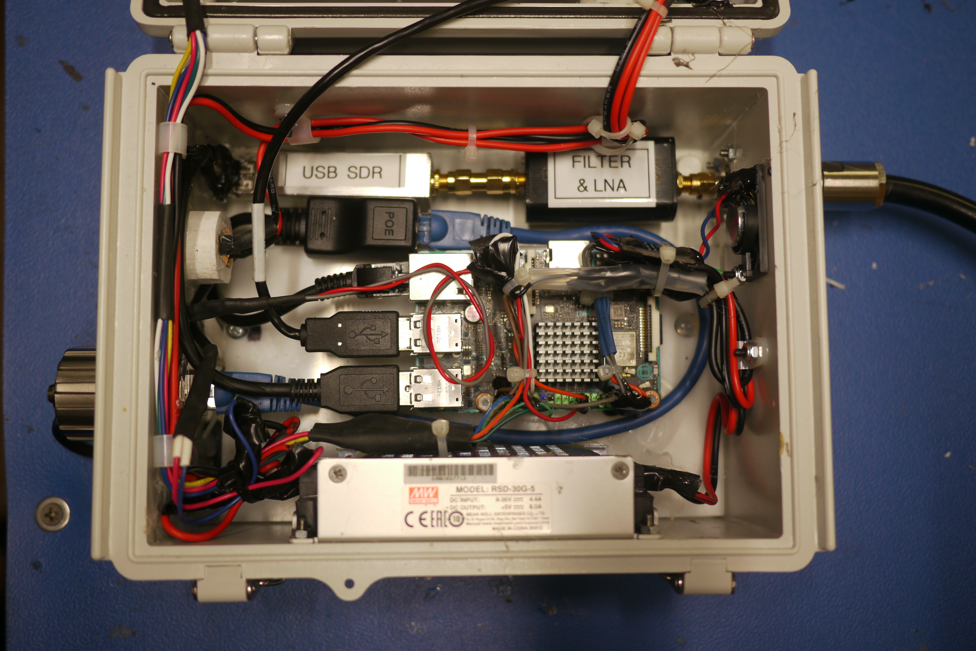
| I I opted for a BUD enclosure [link] as the host for this contraption. There's an adage 'pick an enclosure bigger than you think you need', i did not follow that advice so the final layout is a bit clutered. First things first, the important bits. There are a number of penetrations in this thing, antenna (N-Type connector), Power, Ethernet, mounting screws and hardware, and finally the LCD display. I started with the defining bit, the N-Type connector that mates the RF hardware to the outside world. | 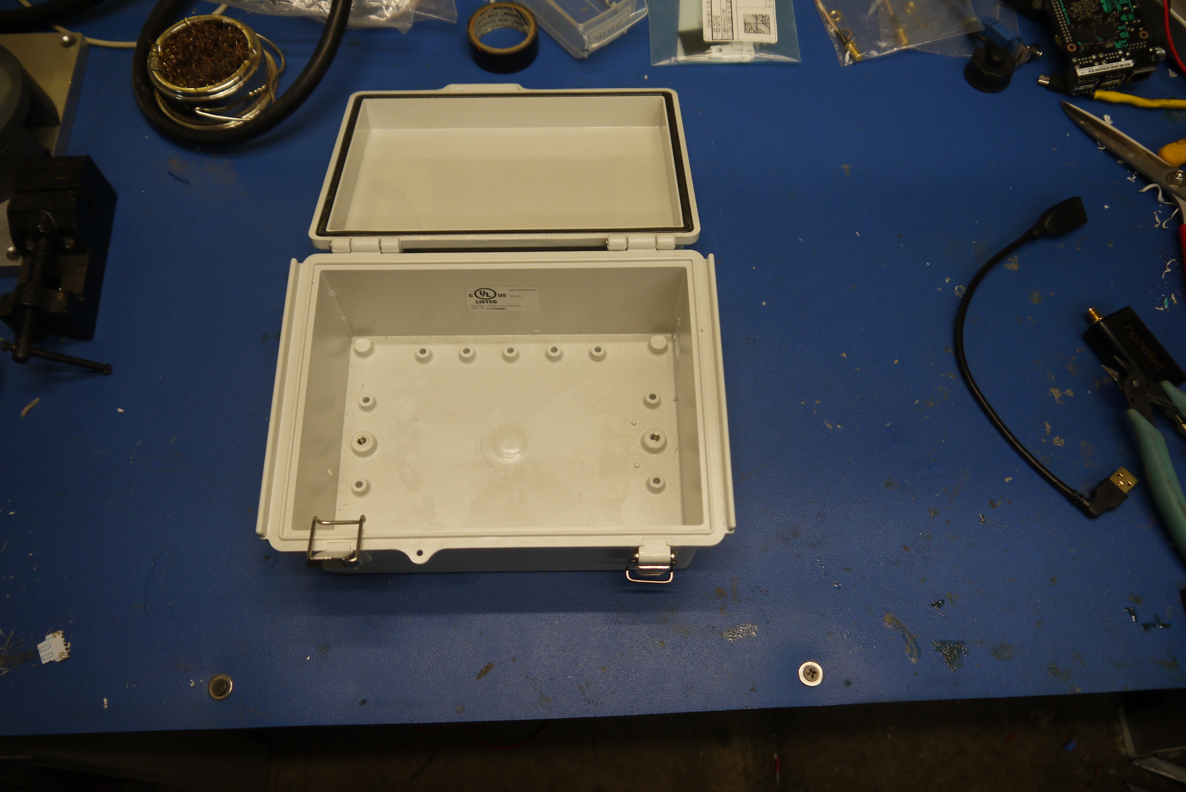 |
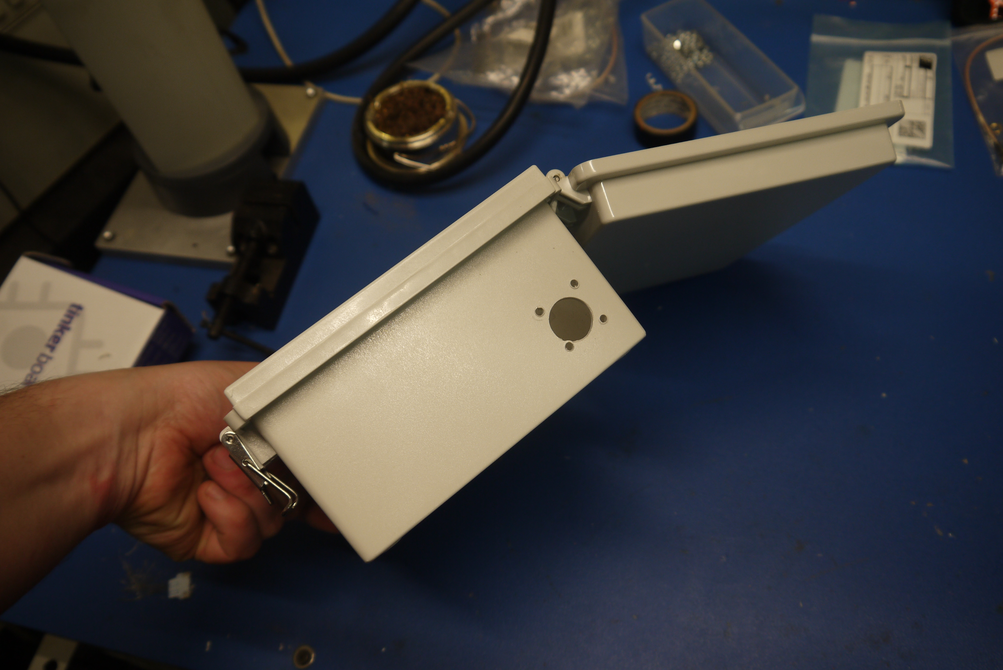 |
| I had dug around on digikey and come up empty, panel-mount N -Type connectors were rare and the one that looked reasonable was 60$. Fortunatley amazon saved the day, [link]. The RF stackup is a bit tight, but, by keeping the amplifier and SDR right in line with each other i'm avoiding a lot of RF singnal loss. | 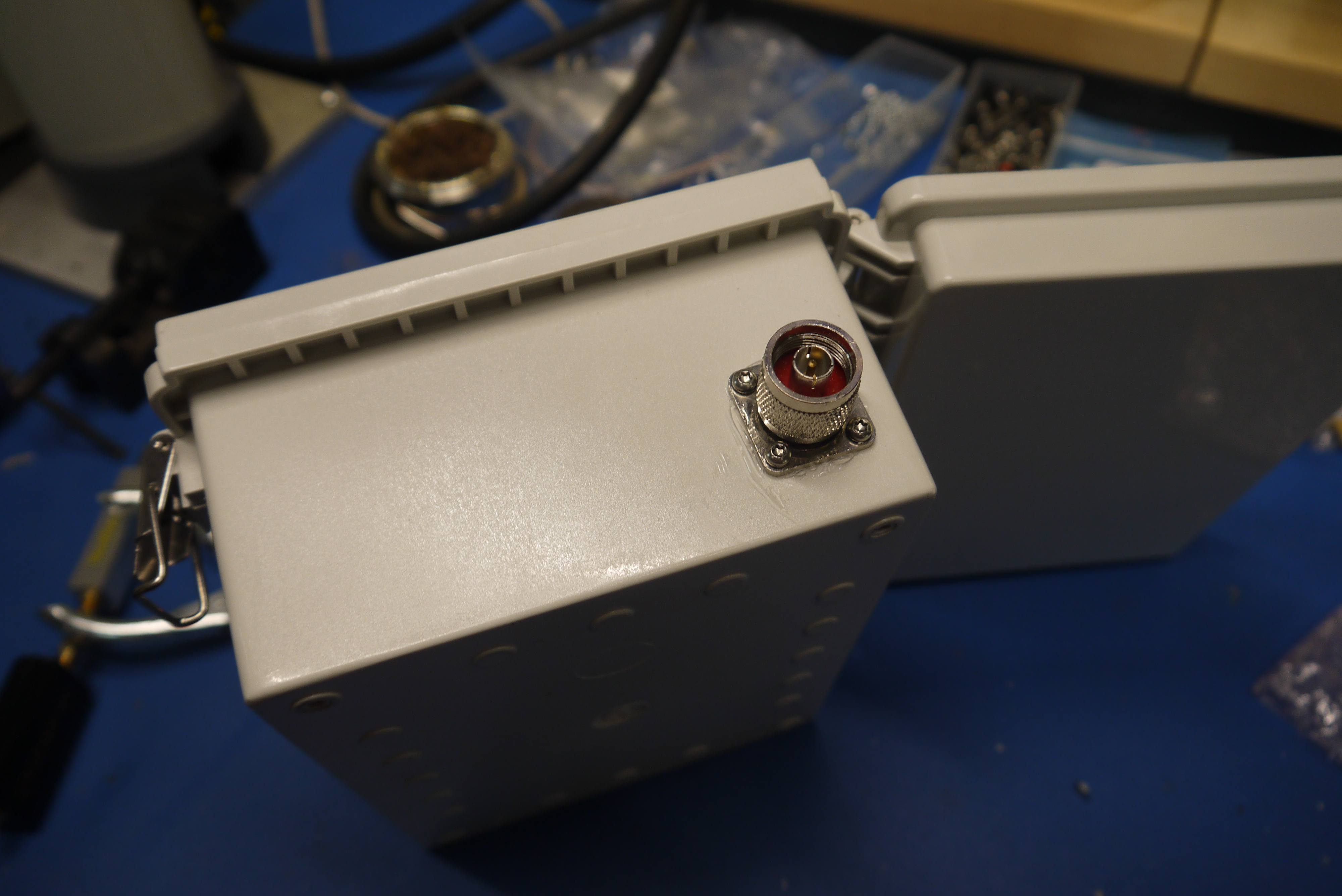 |
 |
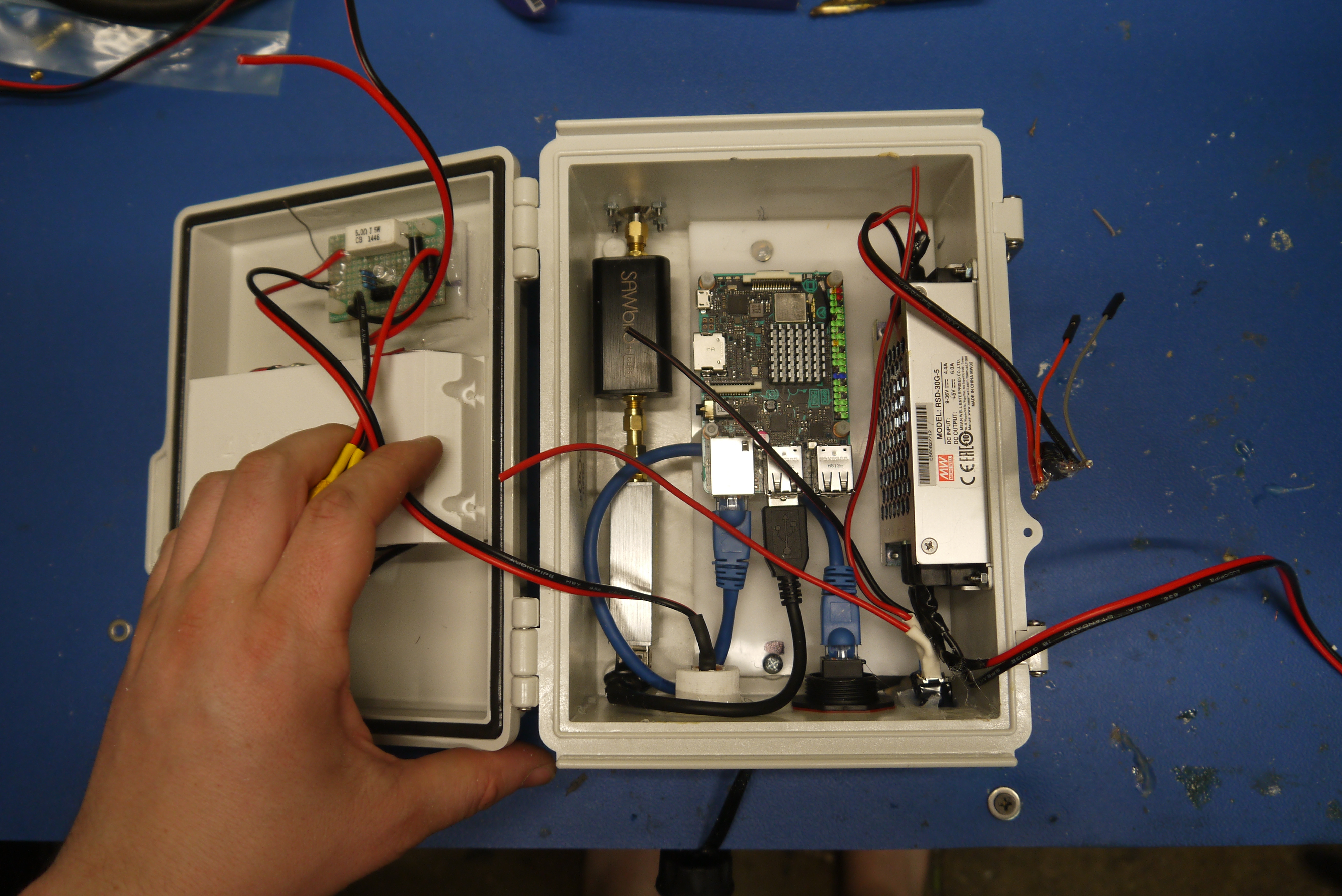
| The placement of things continues. I ended up having to make a specialized short, right angle USB cable to get everything to fit. The 'DC/DC is a 9-36v in 5V6A out meanwell switcher. | 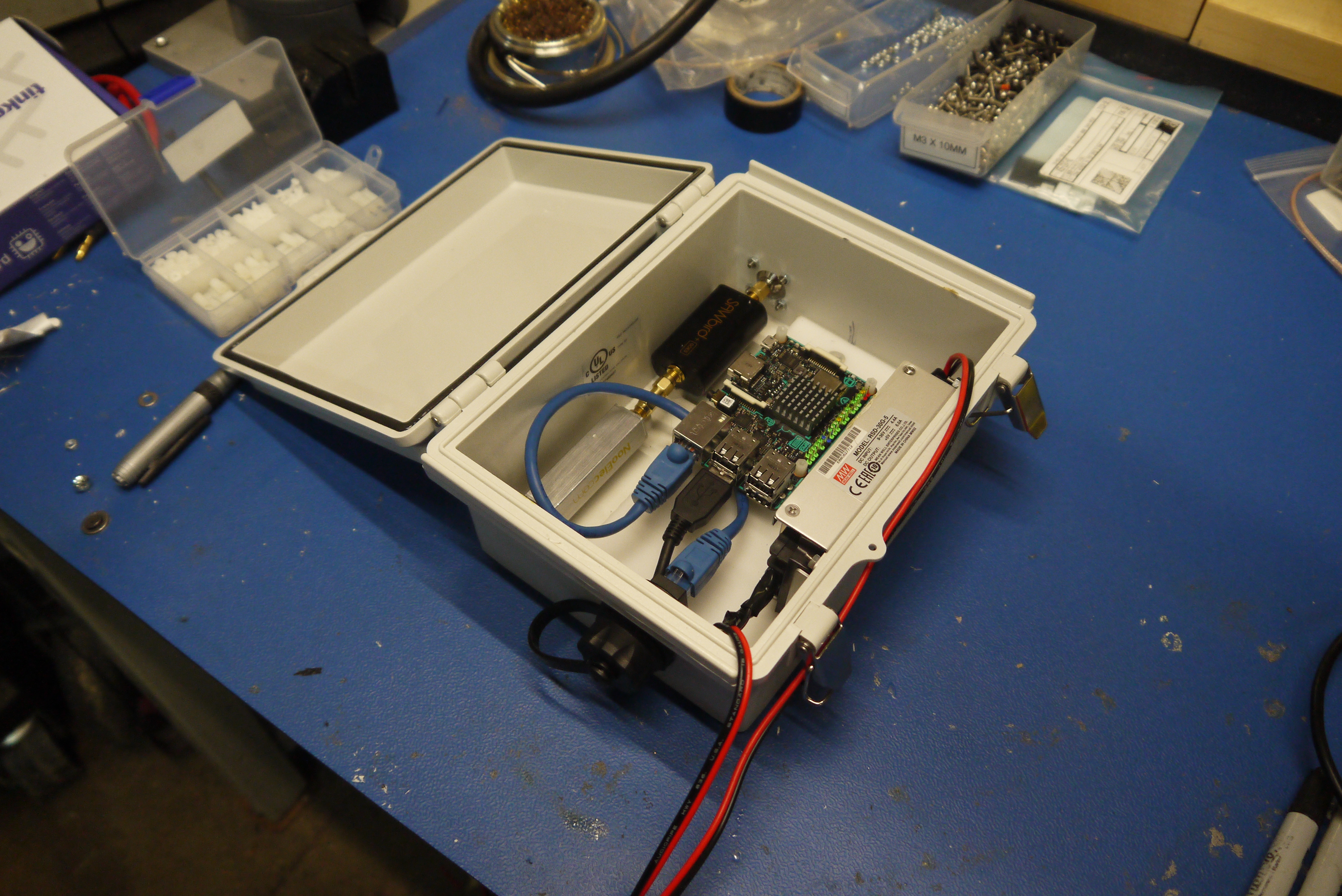 |
 |
| Ok next up cutting a hole for the display, adding the front-facing buttons, ethernet connector, power switch and power connector. As this was 'prototype-y' i used what i had on hand. The on-off switch has a convienient 12v led setup inside. Unfortunatley its incredibly easy to accidentally turn on. The 'panel mount xt90 connector' is also a bit goofy, and by no means waterproof. The front facing pushbuttons are a good choice, they are actually IP68. |  |
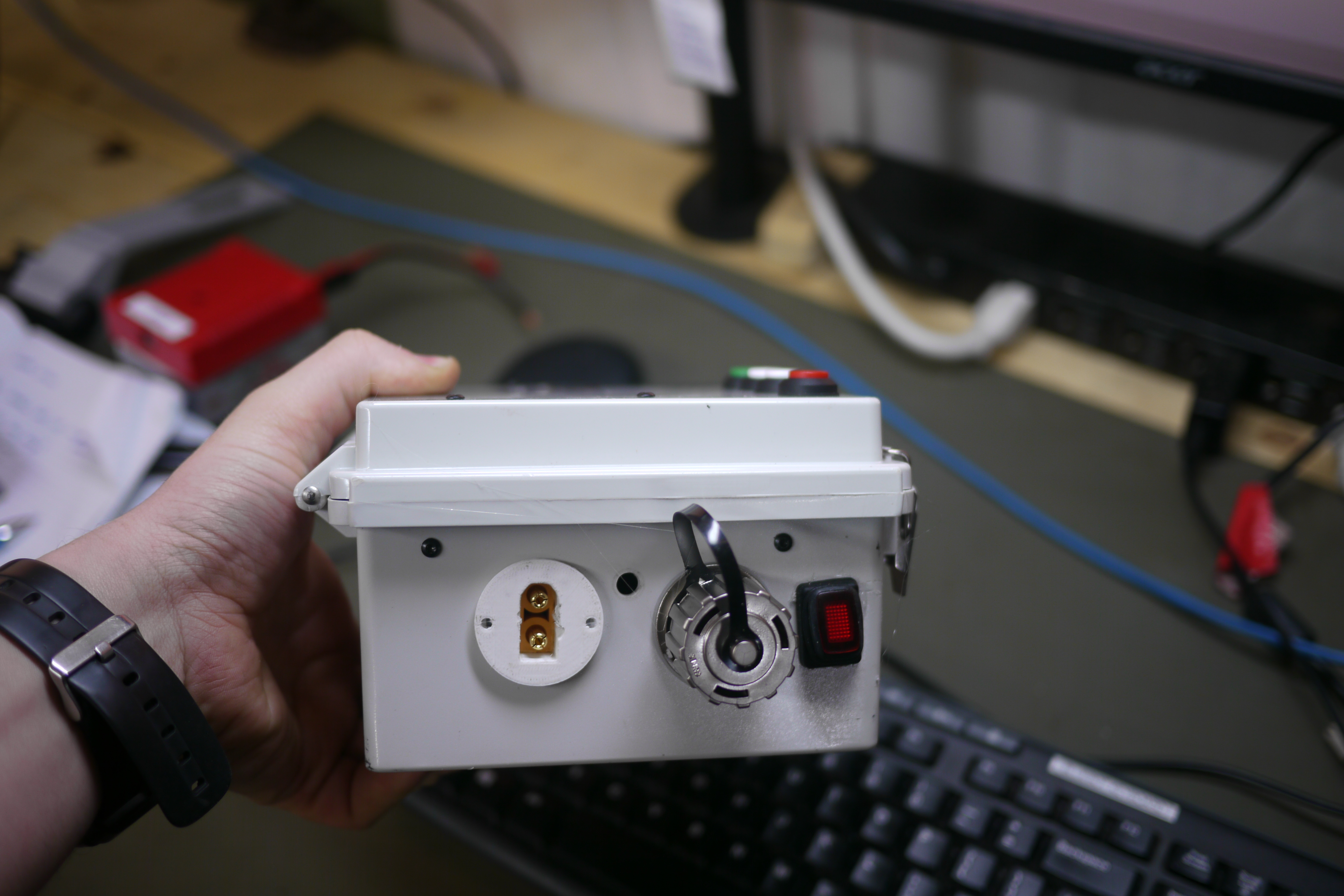 |
| Wiring
in the buttons and perhiperals. The LCD used in this build is the 16x2 RGB adafriut character display with a USB interface. This makes it quite convienient to setup / adapt to other displays. The pushbuttons are wired to a central +5v feed, and then each have a 1k pulldown with a 10nF capacitor to do a bit of button de-bouncing. |
 |
 |
| The
cauchophony continues. There are now a few things that need to interface to the tinkerboard, pushbuttons (GPIO) an LED indicator (also GPIO), 5v power supply feed |
|
 |
| Time to cut out the lcd acrylic cover and make a snazzy nameplate for the thing. I headed to the MIT hobbyshop. The only reasonable priced anodized aluminum on mcmaster-carr is this 30 thou thick plate. Its great for nameplates. I cadded up a quick design, used an OMAX waterjet to cut out two from a 6" square plate and then headed over to the lasercutter to engrave some imagery. | 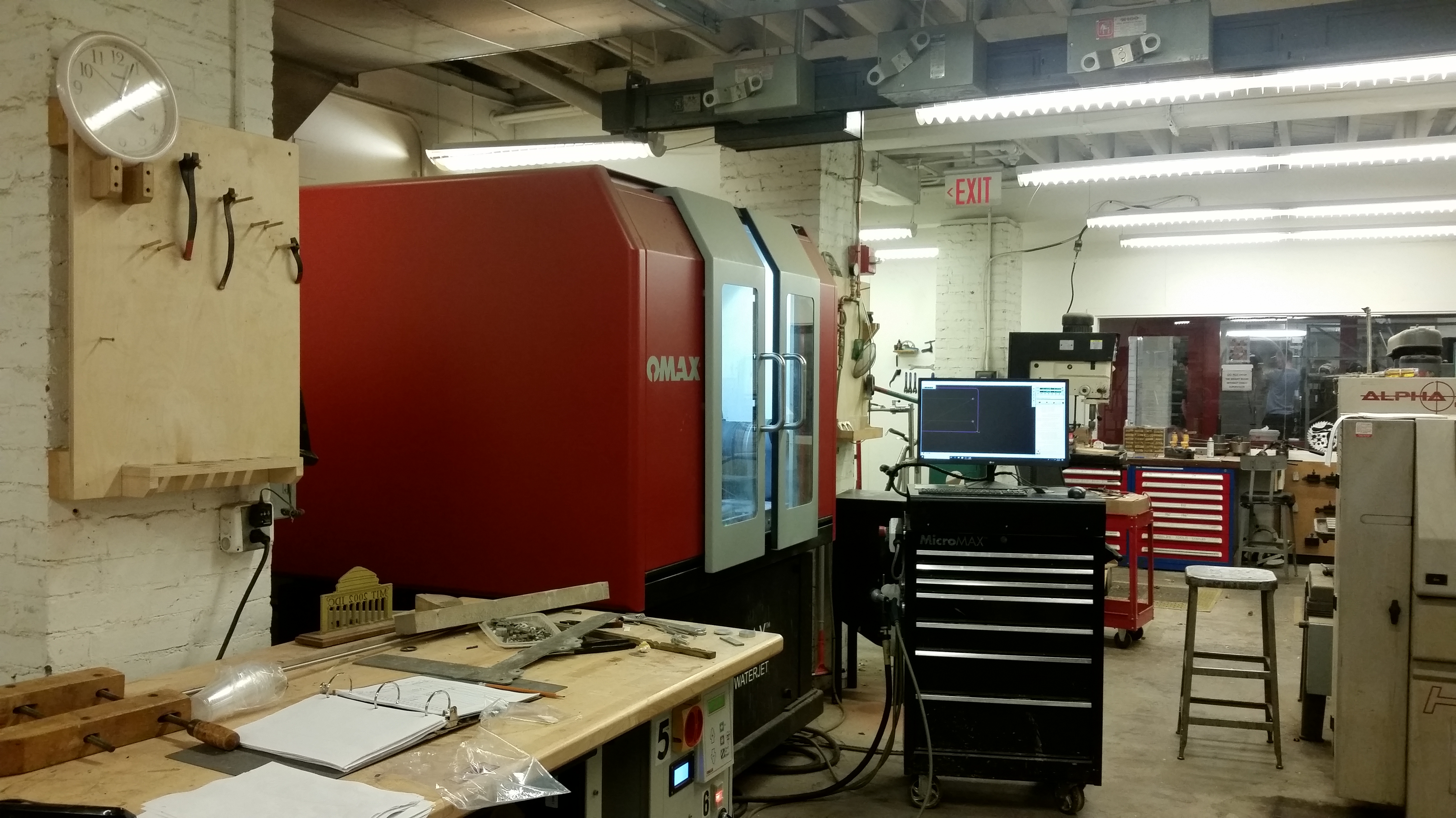 |
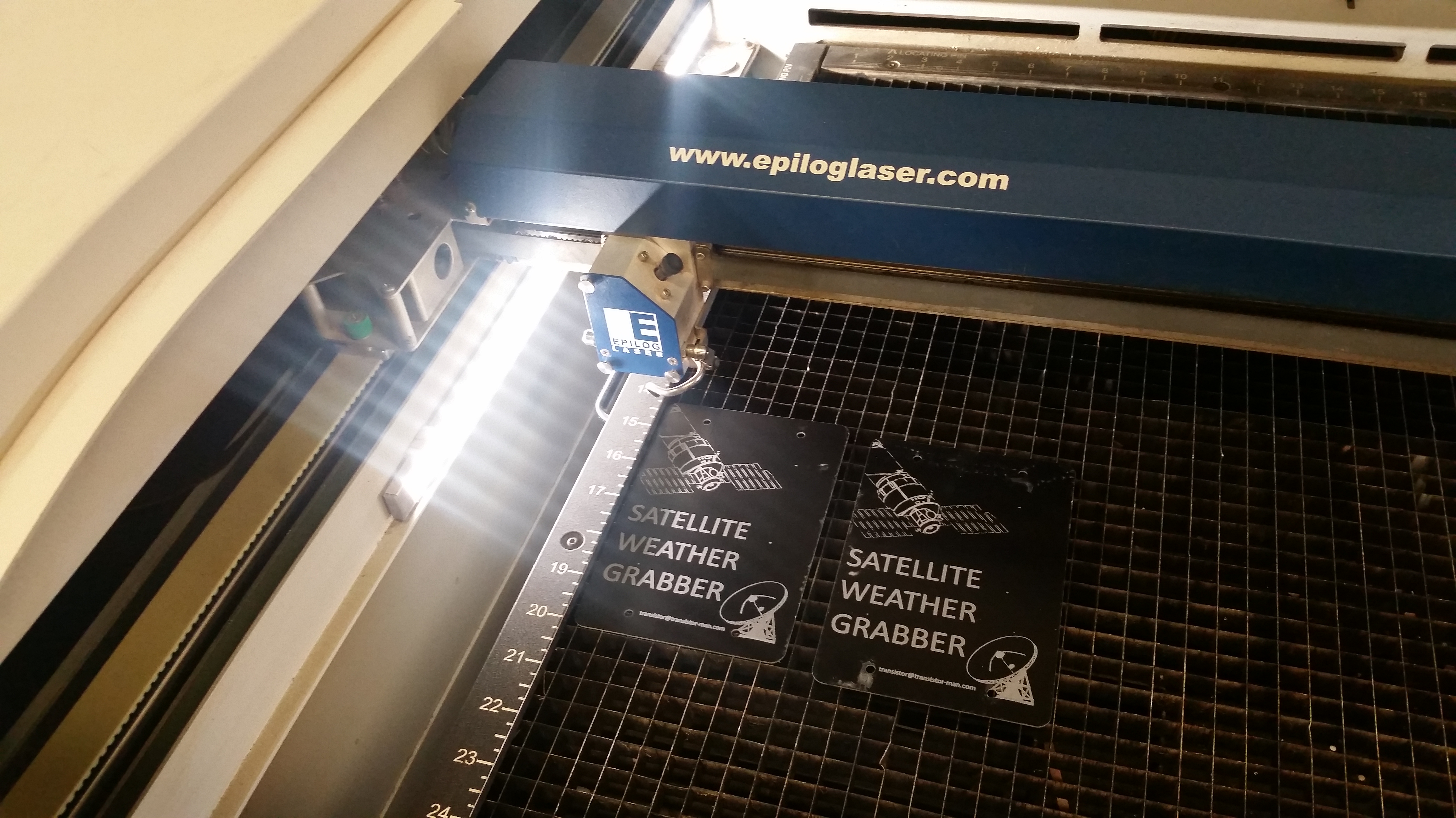 |
| Waterjet anodized aluminum sheet, freshly cut from the waterjet and some 1/4" thick acrlyic for the LCD cover. I ended up not totally loving the design of 'just glue it in place. Due to the LCD bumping right up next to it, i think i will try some very low profile screws and a gasket for a second version. | 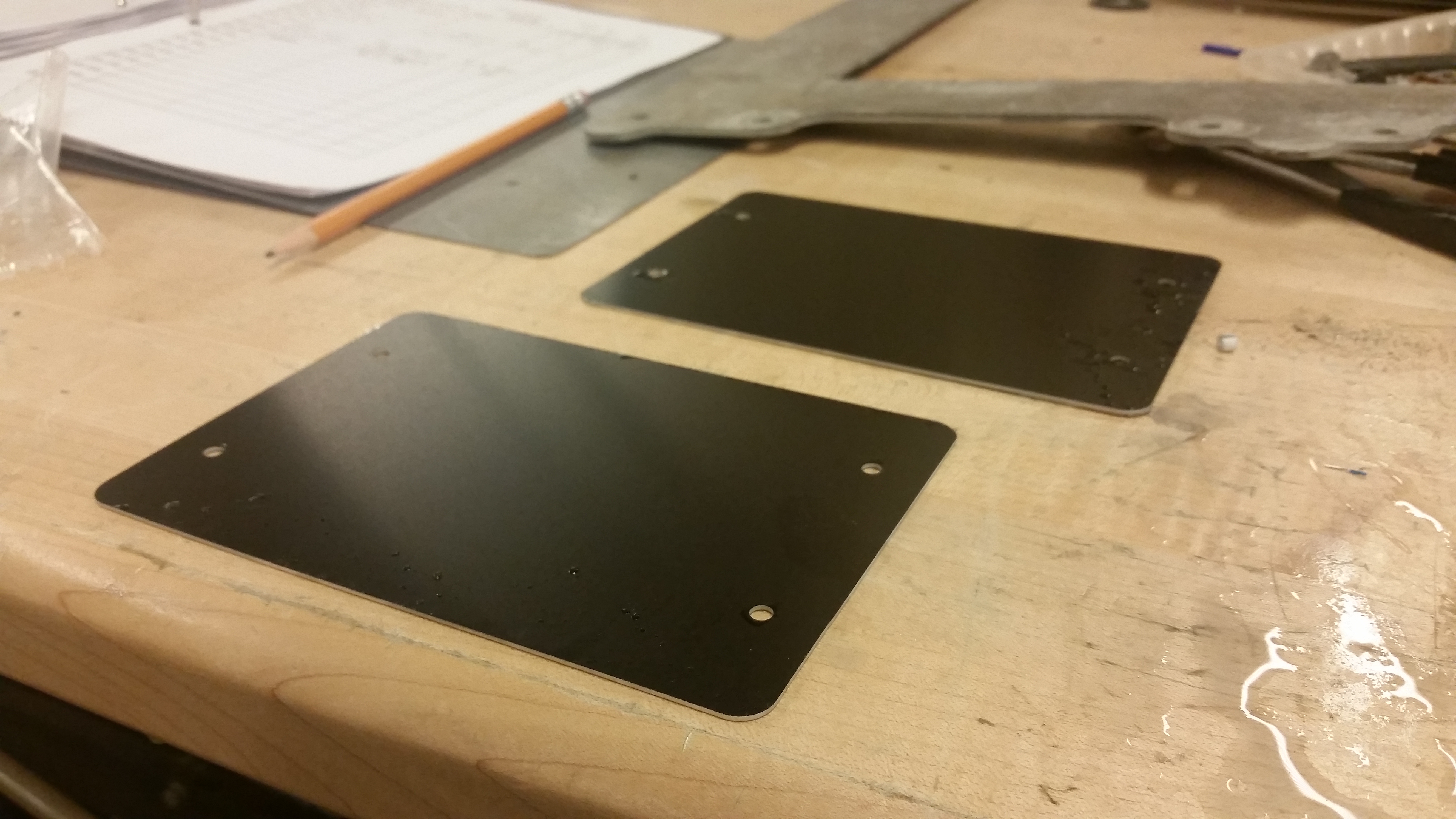 |
 |
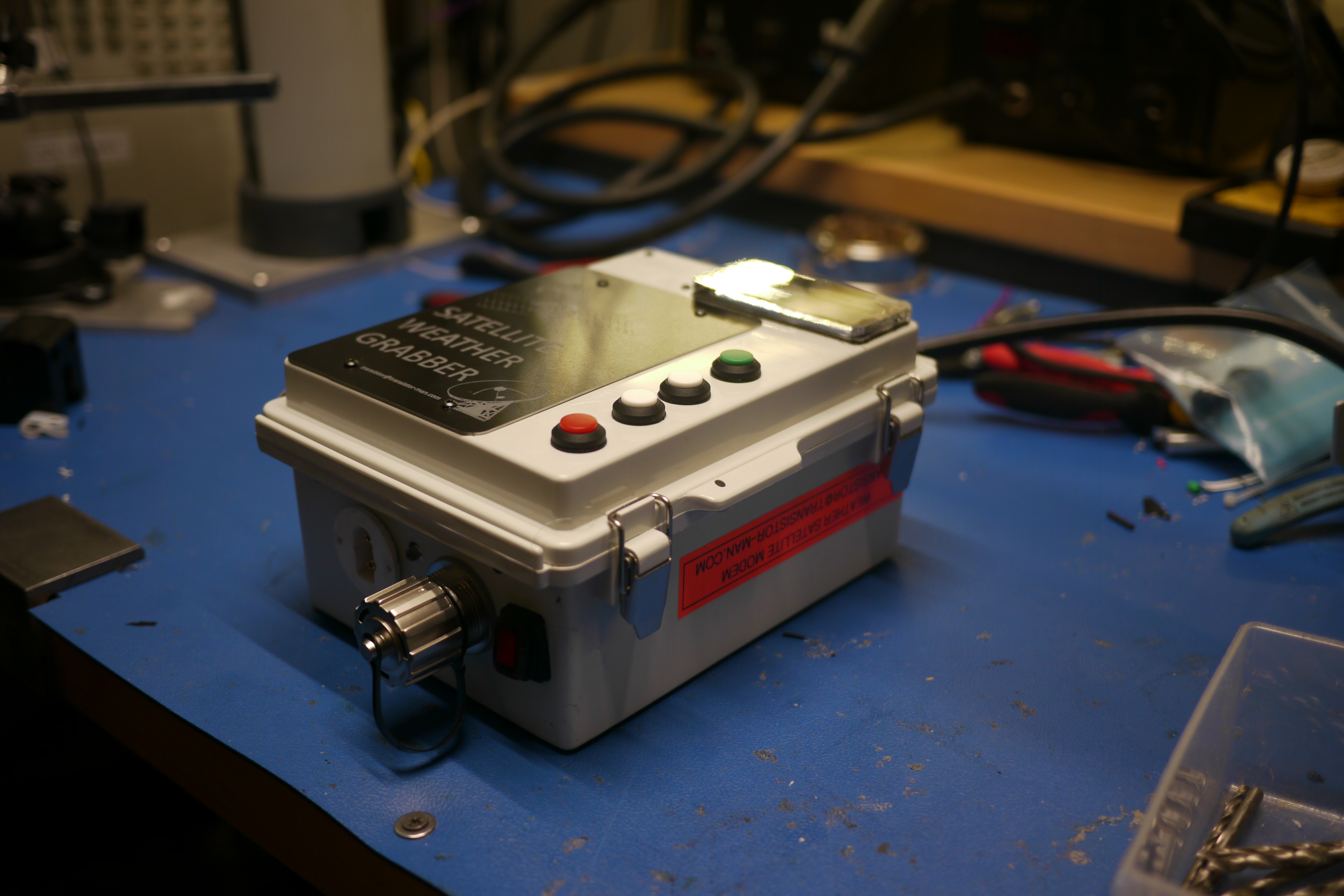
| Things are coming together! I use the screws that hold the battery module in place to also hold the engraved sign. This sign is mostly to add some information about the hardware, such that if it is found un-attended its less likely to be confused for something nefarious. |  |
 |
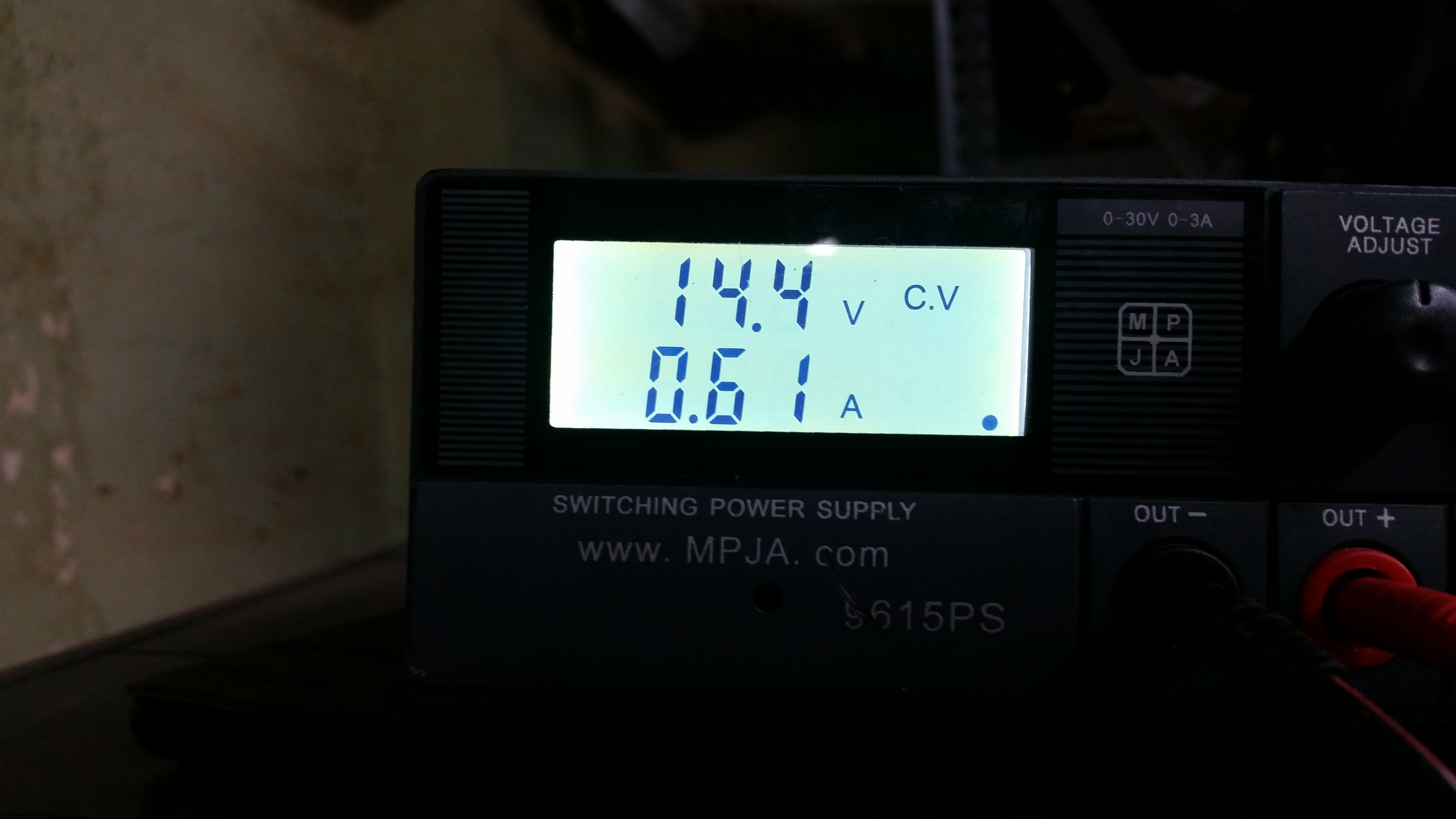
| How are we doing on power? Excellent question. 14.4v is the nominal voltage for a fully charged 4s LiFe battery module, After the internal battery was fully charged i did a benchmark with an external power supply. I used a CPU stress test terminal application to simulate full CPU load. Sitting idle, with the lcd running, the whole apparattus pulls 230mA, while at full tilt on the CPU, its 610mA. As there is a DC/DC regulating the input from the external battery, this will change to supply a stable 5v to the single board computer, but its a good benchmark. |  |
 |
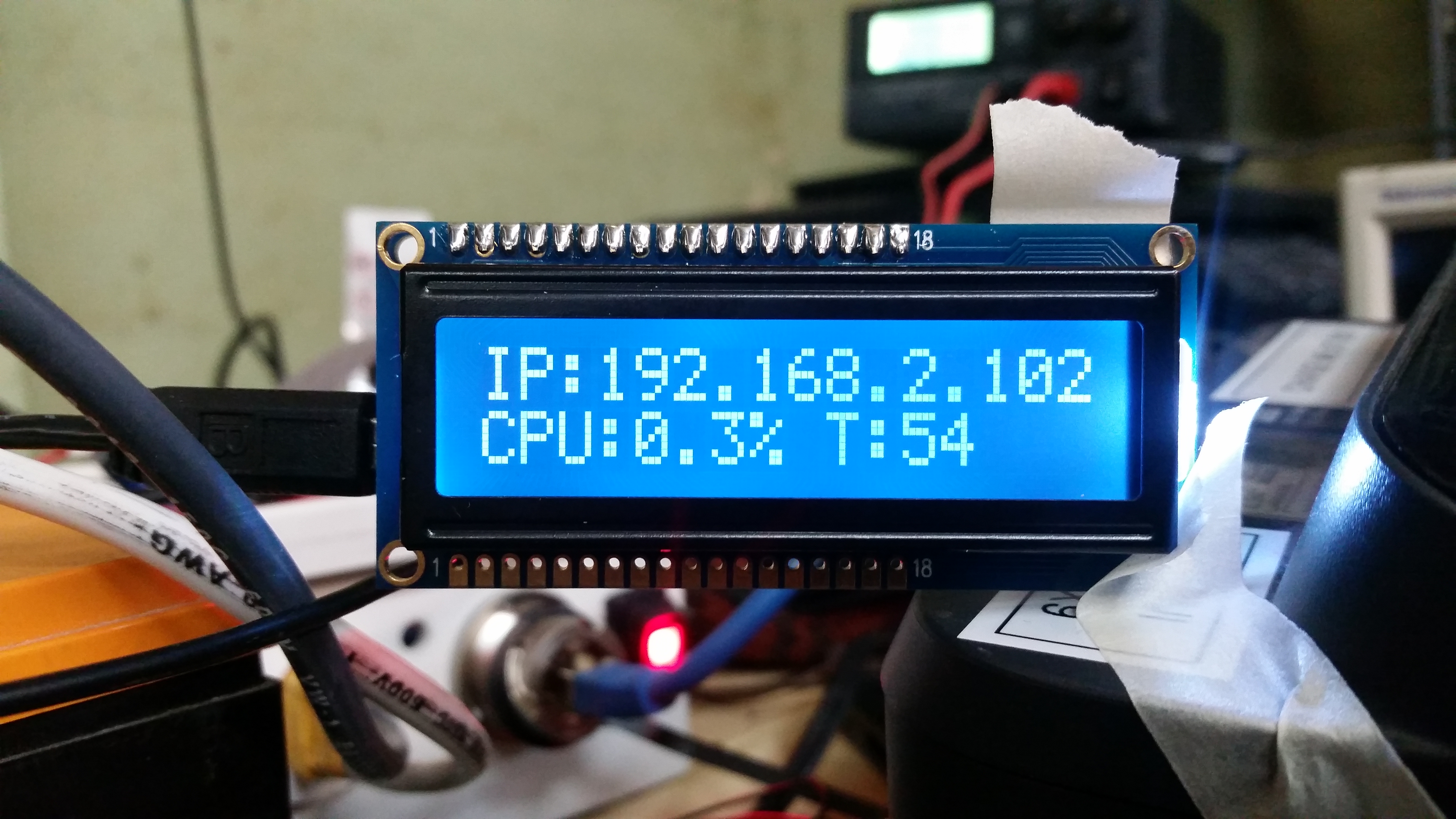
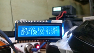
| Speaking
of that CPU application. As part of the 'i'd like this to be standalone so i dont need to drag around a laptop' I spent some time pulling out the reported IP along with the reported % CPU usage and finally the reported CPU temperature. This is fairly useful especially for debugging. The LCD of choice is an adafruit RGB backlit serial interfaced lcd, model xyxyxy [link]. |
 |
 |
| The panels were cut from 6" square anodized aluminum sheet |  |
| Laser engraving the coverplate |  |
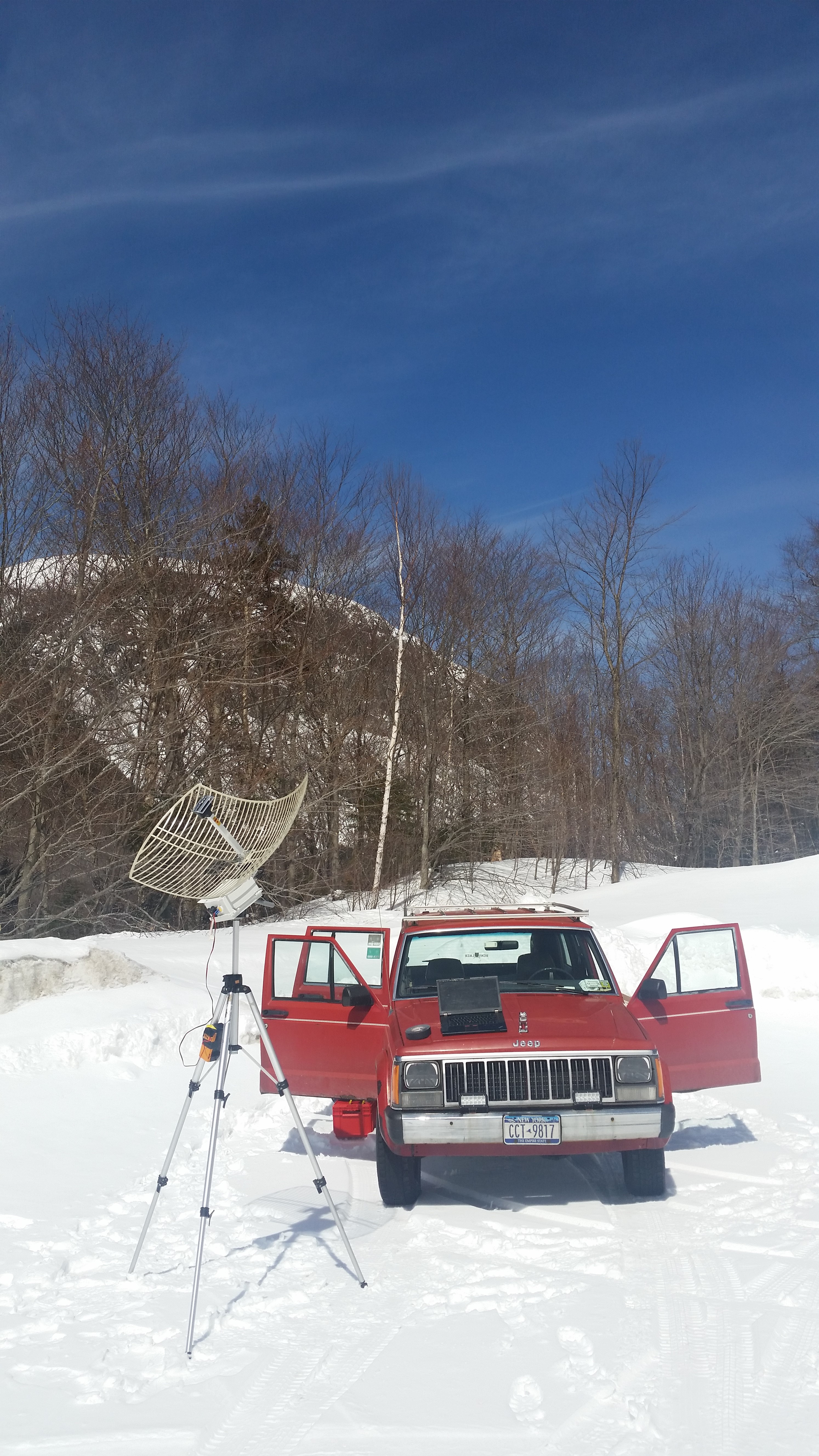
| Trying to pickup GOES-16 and
GOES-17 while still being on the east coast. So this was a bit more difficult than i had planned. My plot was simple, GOES-17 is really similar to GOES-16, just way off on the horizon and a different carrier frequency. If i find some altitude and set the recieve frequency for GOES-17 its feasible to grab it. nominally its about 9 degrees above the horizon in massachussetts, which, is way too low to pick up. With some altitude (ahem NH mountains) the low horizon is not as obstructed. As it was also quite cold out, i made a laminated sign to ensure people who found this gadget didnt mistake it for something nefarious. Comically my cell phone doesnt work that far north, so, uh, not sure how that contacting part would play out. |
 |
|
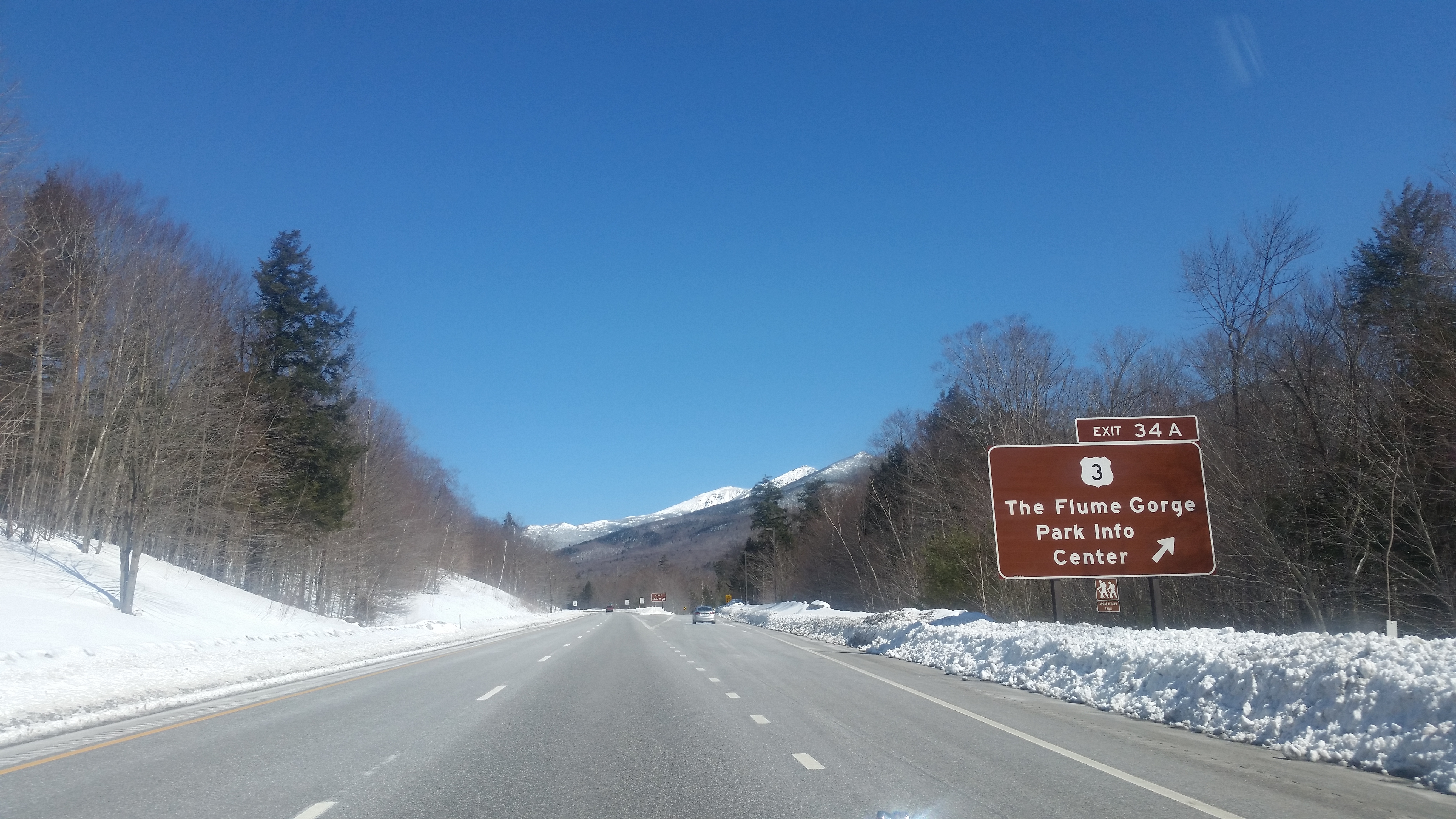
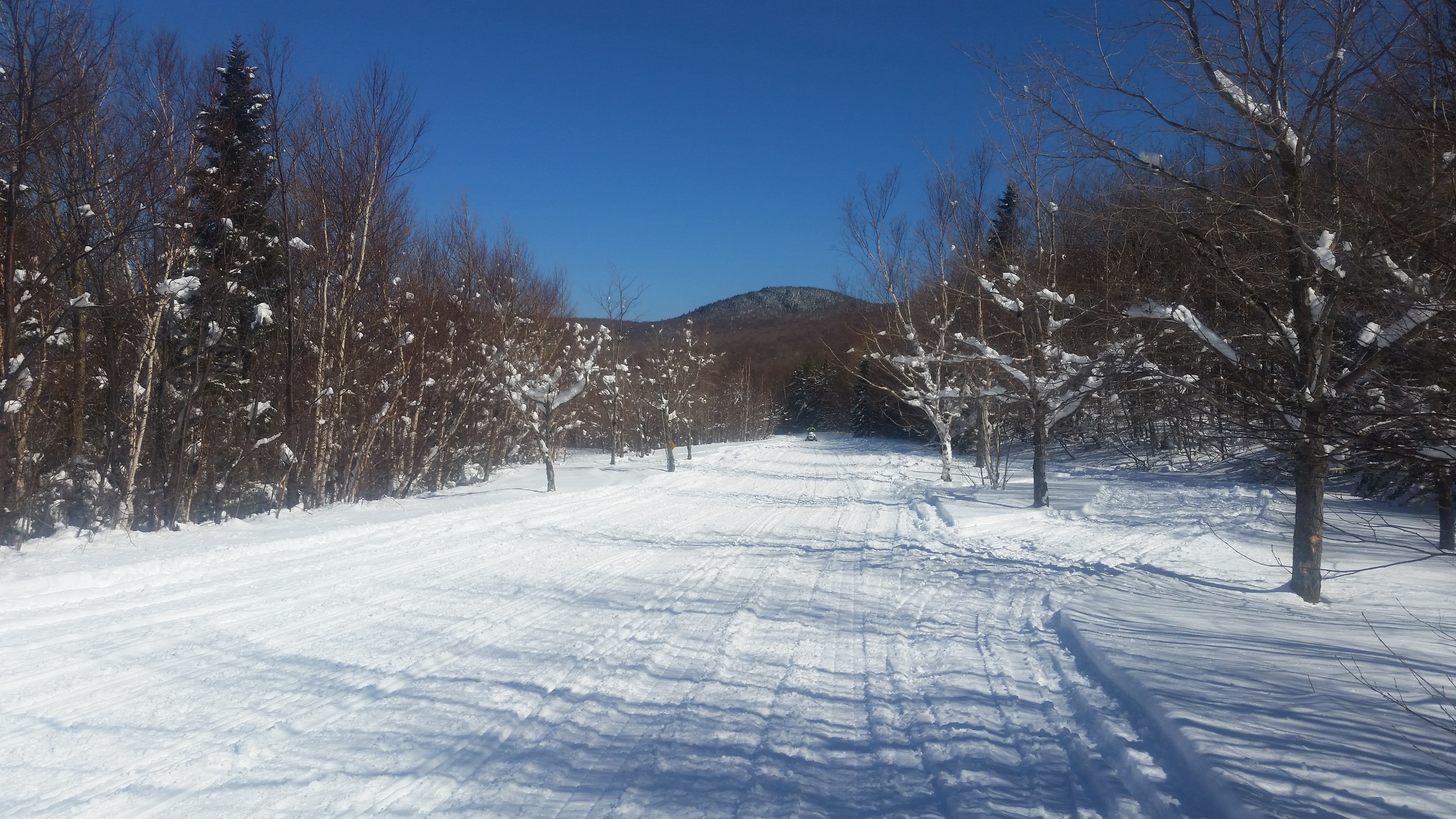
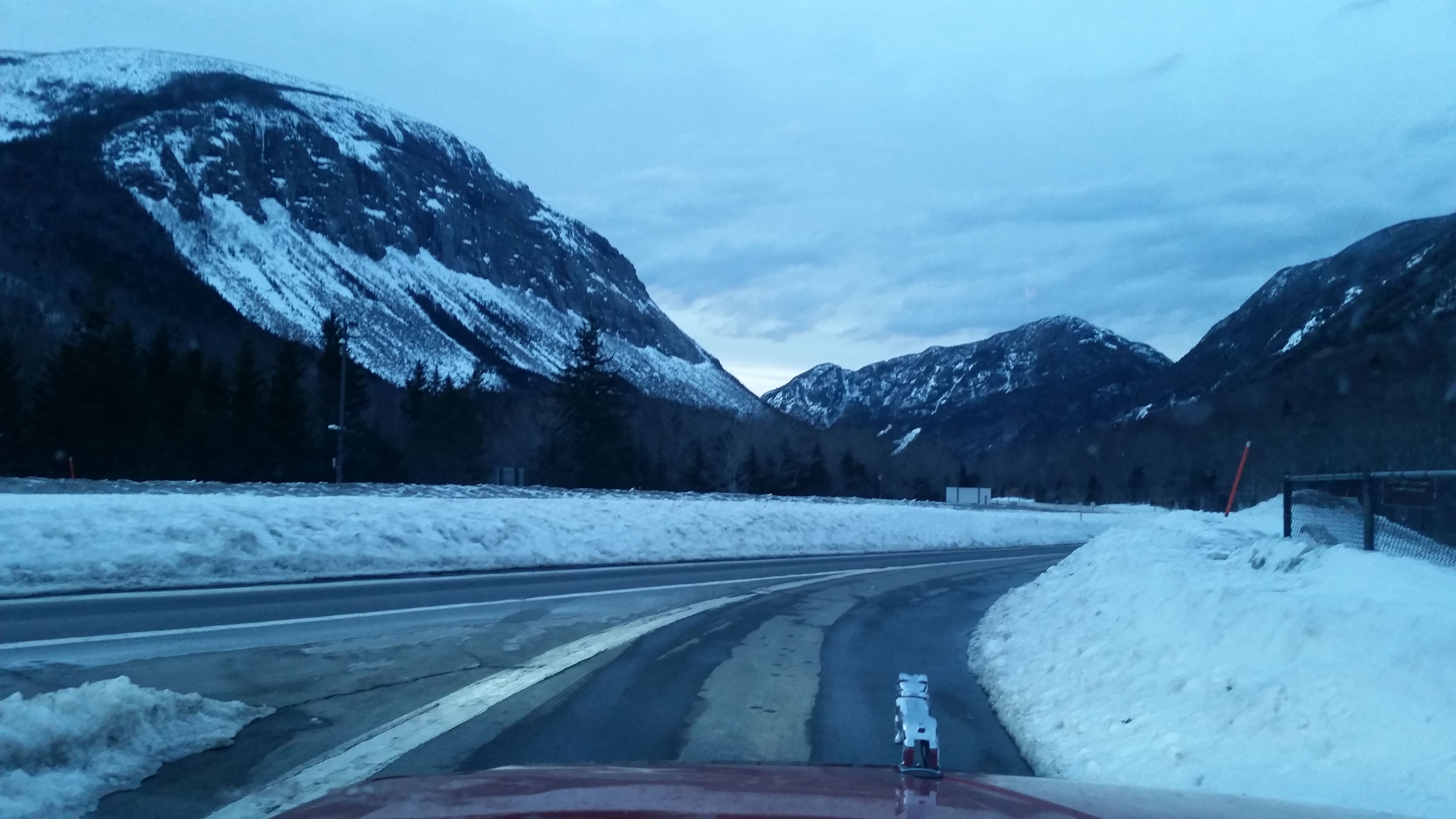
| Off
to NewHampshire Land Hils and snow. At this point in the season, massachussetts was snow-less, so it was pretty nice to see fluf around again. I chose Artists Bluff as the first testing point, as, i didnt know how well the roads on the kankamangus highway would be. |
 |
 |
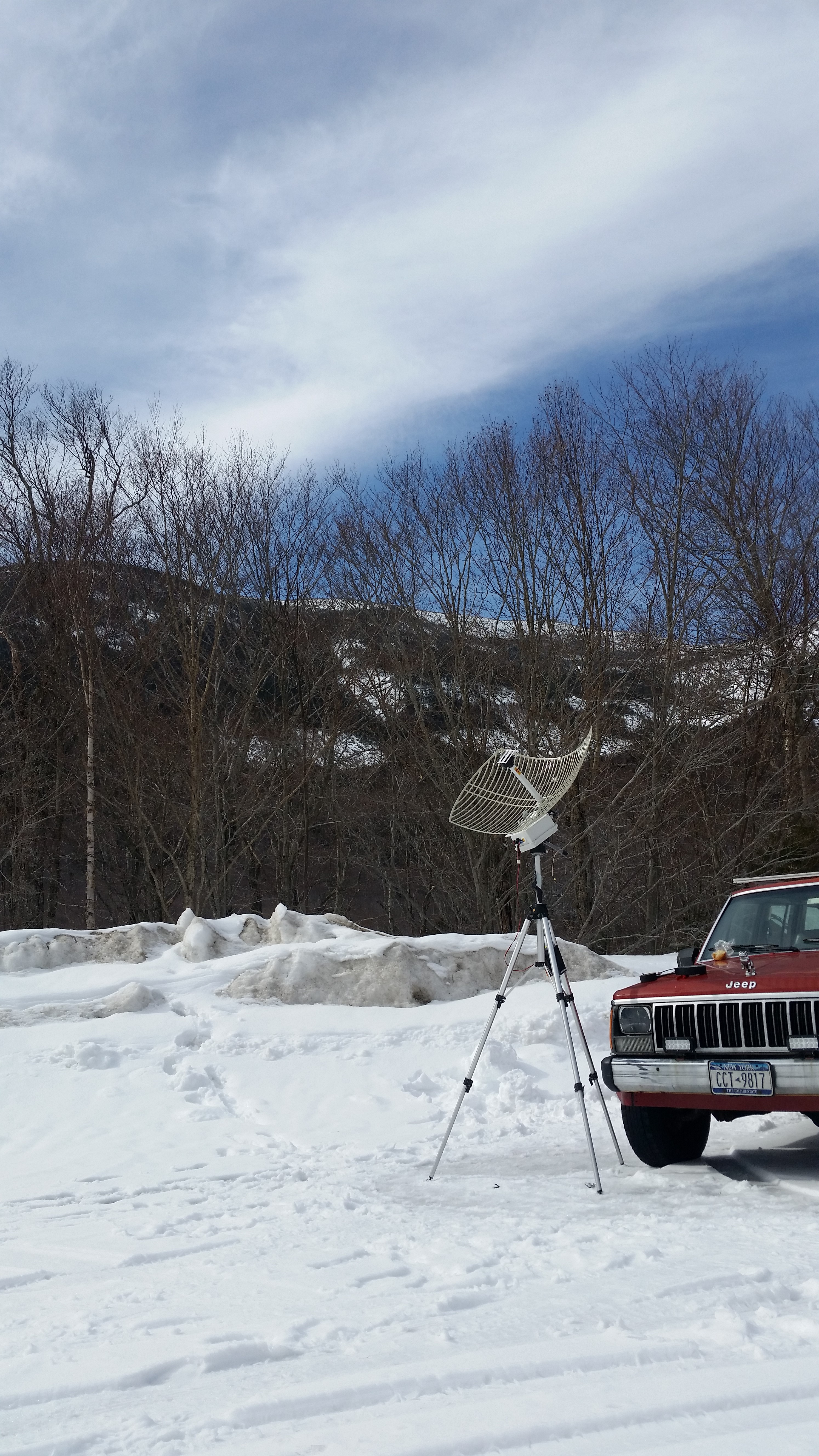
| THE
SETUP I made a few mistakes on this day, but there was a lot of learning. It was a bright clear day, better weather than i could ask for, however, the bright sun and the bright reflective ground made it impressivley bright out. I forgot sun-glasses, so there was a lot of squinting. Try reading a laptop on the surface of the sun. I also 'fixed things too much' right before the trip. I learned that small usb wifi cards can be used to synthesize an access point! Quite nifty! So at the last minute i added the feature of 'it makes its own AP' such that i wouldnt have to run a patch cable to a switch or whatnot. This was a mistake. The wifi card, in such close proximity to the antenna resulted in A LOT of interference. I couldnt find anything, GOES-16 or GOES-17. I checked the map, i doublechecked south. Nothing. just a pile of dropped packets. It took a few hours to conclude that the wifi itself was interfering. Such is the way of lost data. Progress was eventiually made. Interestingly, the tripod itself started to move. As the snow melted a bit, the tripod sunk in ever so slightly. More lessons learned. With the extra sun-glare i did come up with an idea, why not make acoustical feedback on the satellite reciever, for allignment. IE change pitch / frequency as you get closer to the threshold of <400 viterbi error corrections. This actually looked promising. |
 |
 |
| Still a wonderful day. Local NH quisine, fresh air and 4WD activities abounded. I've done some plotting and determined that, if i can actually pull goes-17 from the east coast, I may make two of these deployable contraptions and GRAB EXTRA SATELLITE GOODNESS. | 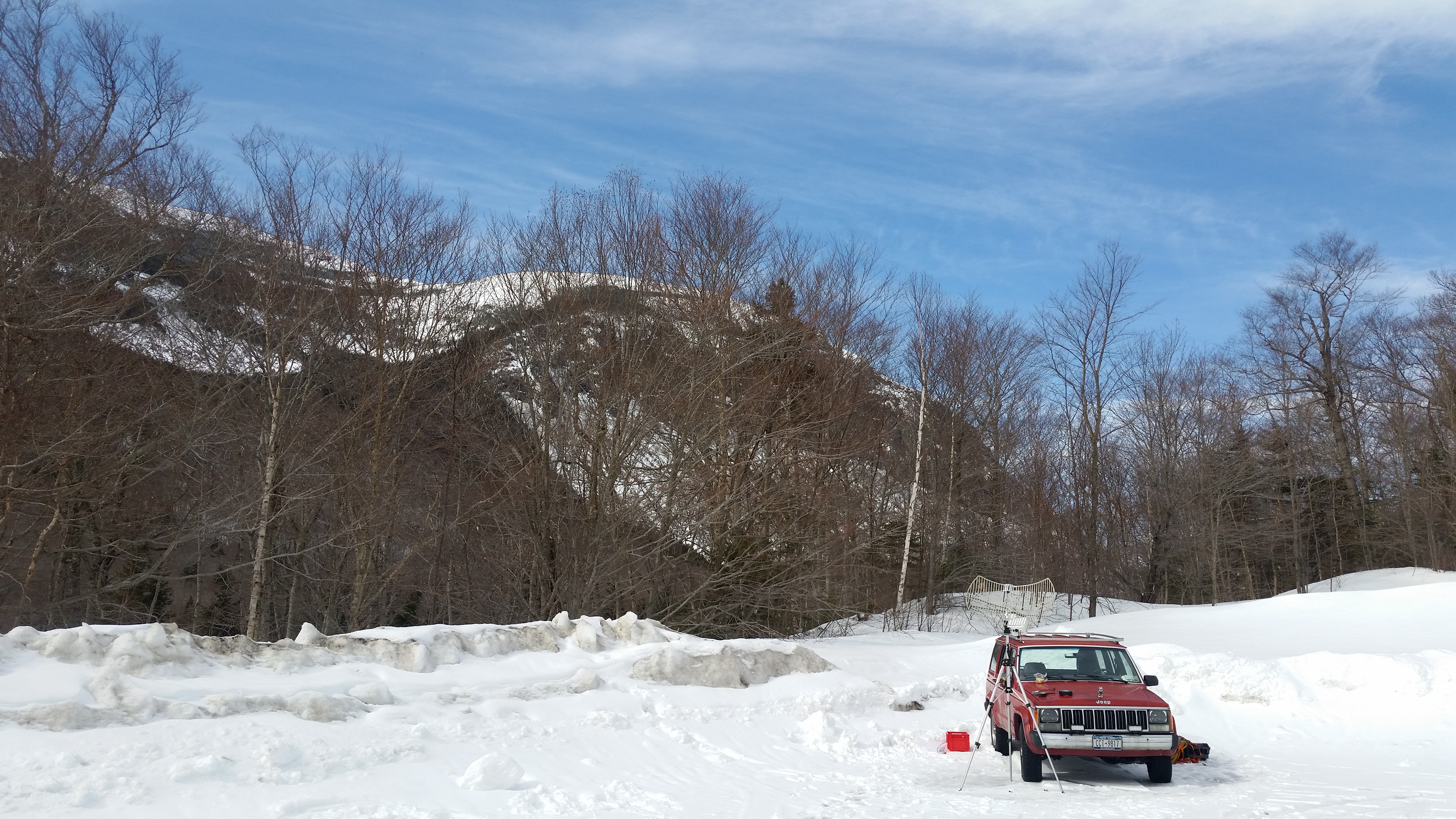 |
 |
(There's
other photos in the photo gallery)
Concluding Remarks:- Its remarkable.
| From the sponsors: |
|
|
| Comments: |
|
HTML Comment Box
is loading comments...
|
Dane.Kouttron
Rensselaer Polytechnic Institute
Electrical & Electrical Power
631.978.1650
