Dane.Kouttron
[2.7.19] Chomper UPGRADE: Googley Headlights
| While I was waiting around for actual snow to appear I evaluated some incremental upgrades to the V2 snowblower. Nominally last year's vision system was a bit lacking, but now that there's some reasonable HD footage piping back to the pilot, extra illumination would be fairly useful. Follow along for a short project: unobtrusive huge 6 inch diameter glowing googley eye headlights. |  |
| Background |
Conclusion | Image Directory |
| Video Demo | |
| The
goal here was pretty simple, keep the googley-eye asthetic from the
previous year but also have the lights function as headlights. It
sounded simple, but it turned out way more curious than I had
anticipated. Quick demo video of the lights working shown right. |
| Wait, what now, glowing googley
eyes? |
||
| Fairly simple right? glowy googley eyes. So here's last year's starting point. The eyes were an afterthought to add a bit more character to the contraption. In these photos i was mostly moxking up where they looked reasonable and how far off the impeller they should live. These are taped in place in this image. The actual support is some opaque white acrlyic sheet, heat-bent into shape. | 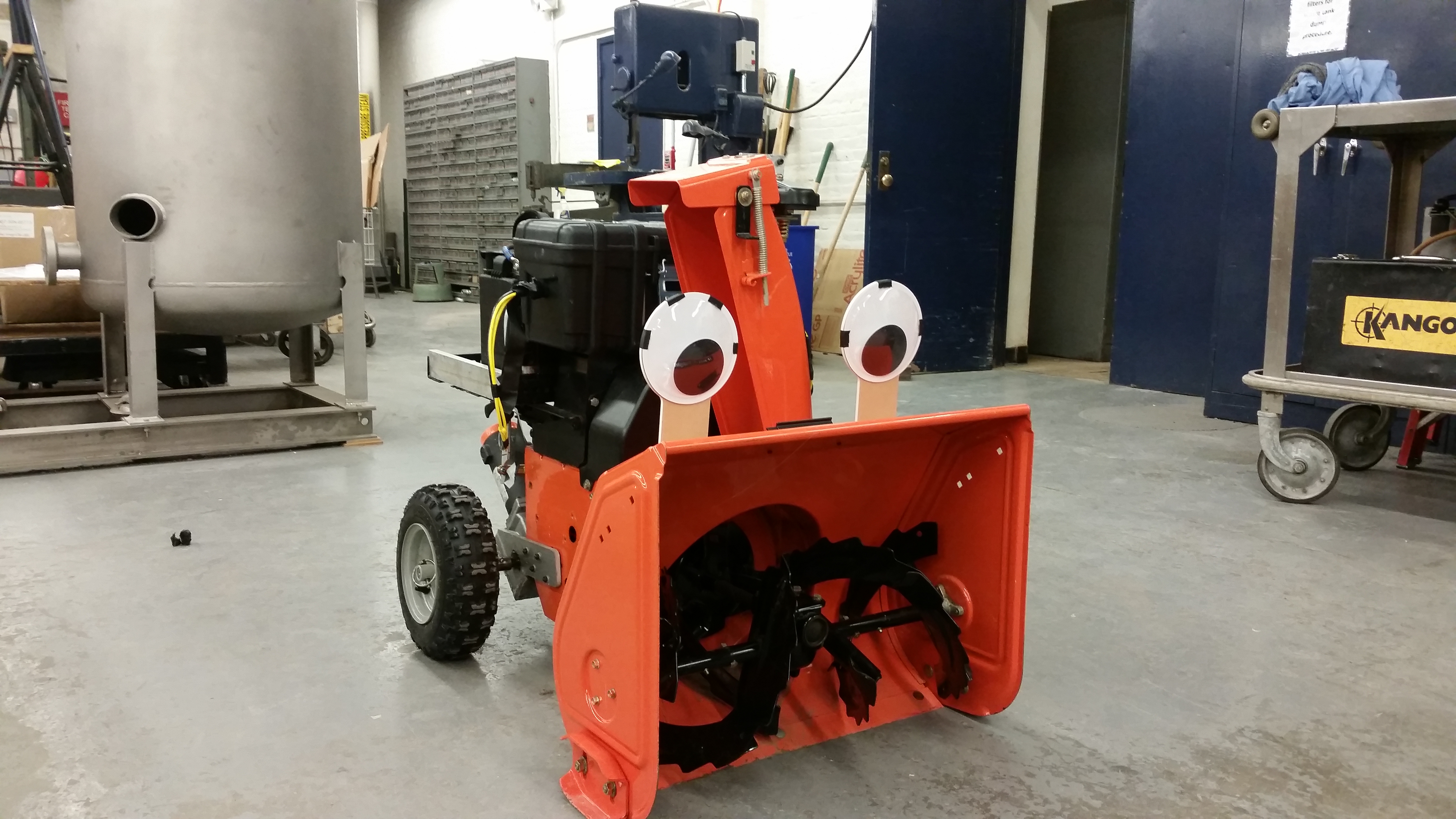 |
 |
| I did some digging. Initially I had plotted using those 'amazon esque' extruded aluminum light blobs, but no matter where I placed them, it made the setup look a bit cluttered. Some ebay hunting later, and behold weirdo hi-hat lights. These were found on ebay [link]. But without useful dimenions there were a few things to be sorted. | 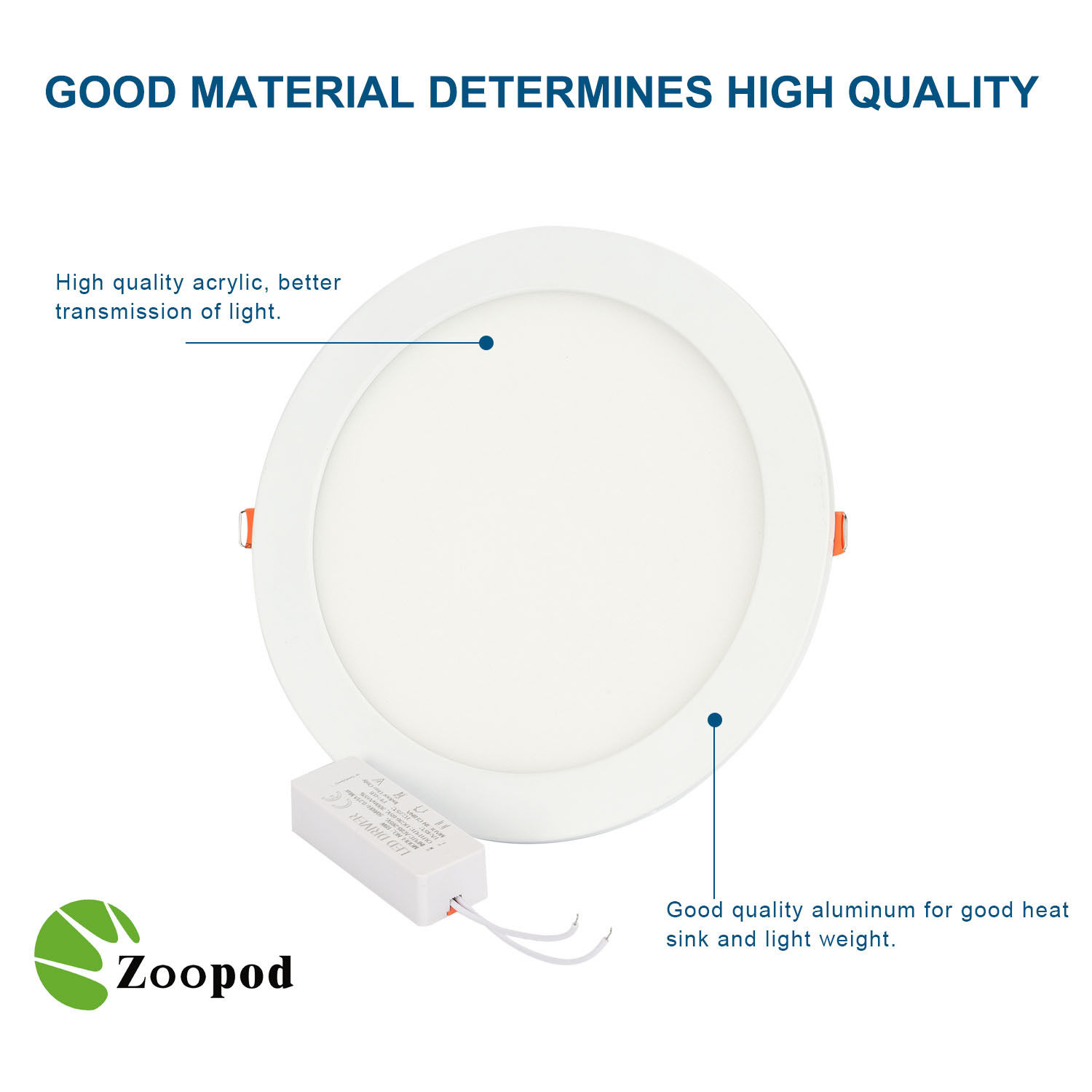 |
 |
| After about a week, the lights appeared. They are impressivley thin. While these are listed as 110-220vac, I guessed that they would have an external inverter to drop things down to a reasonable led drive voltage. They appeared and at first I was impressed, 20$ for 4 lights, at 18w each? Tell me more. It looks reasonable and i initially imagined a single PCB with a pile of small white leds and a lot of diffuser. |  |
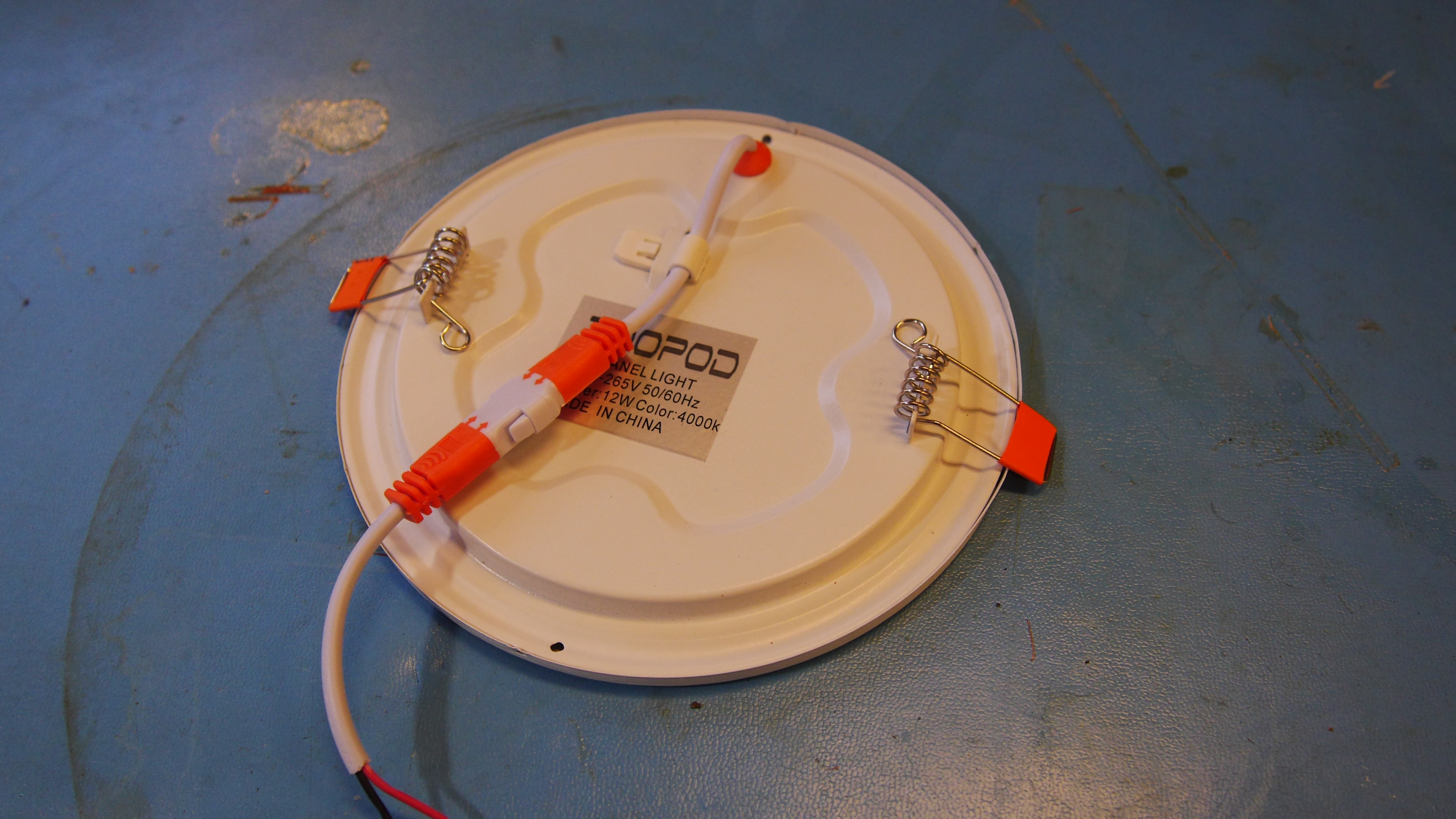 |
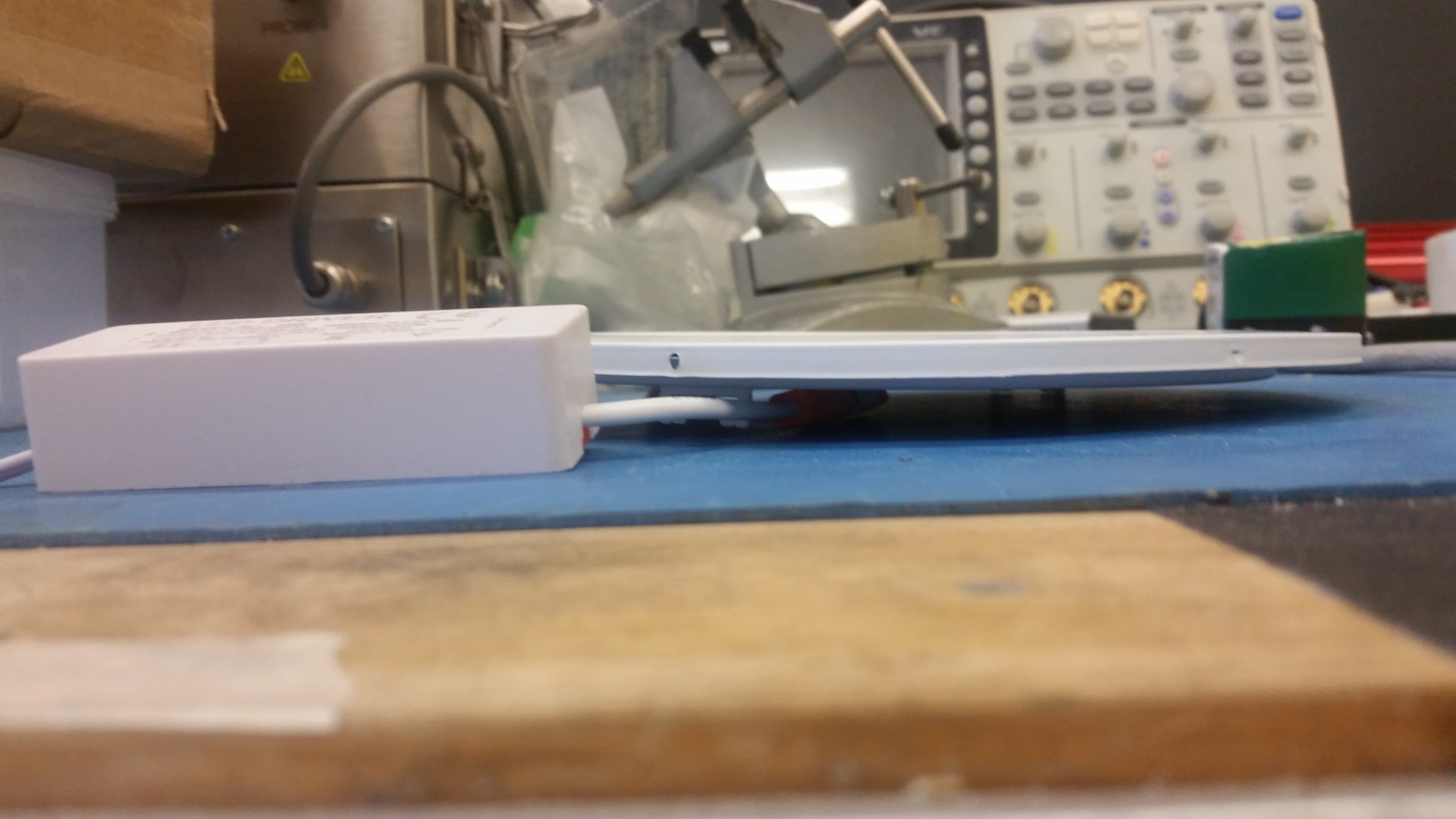
| The light fixtures are incredibly thin, honestly I was impressed. The inverter to power the light was also, maybe 50 grams and 4 times as thick as the fixture. Time to take these apart and see what makes them tick. | 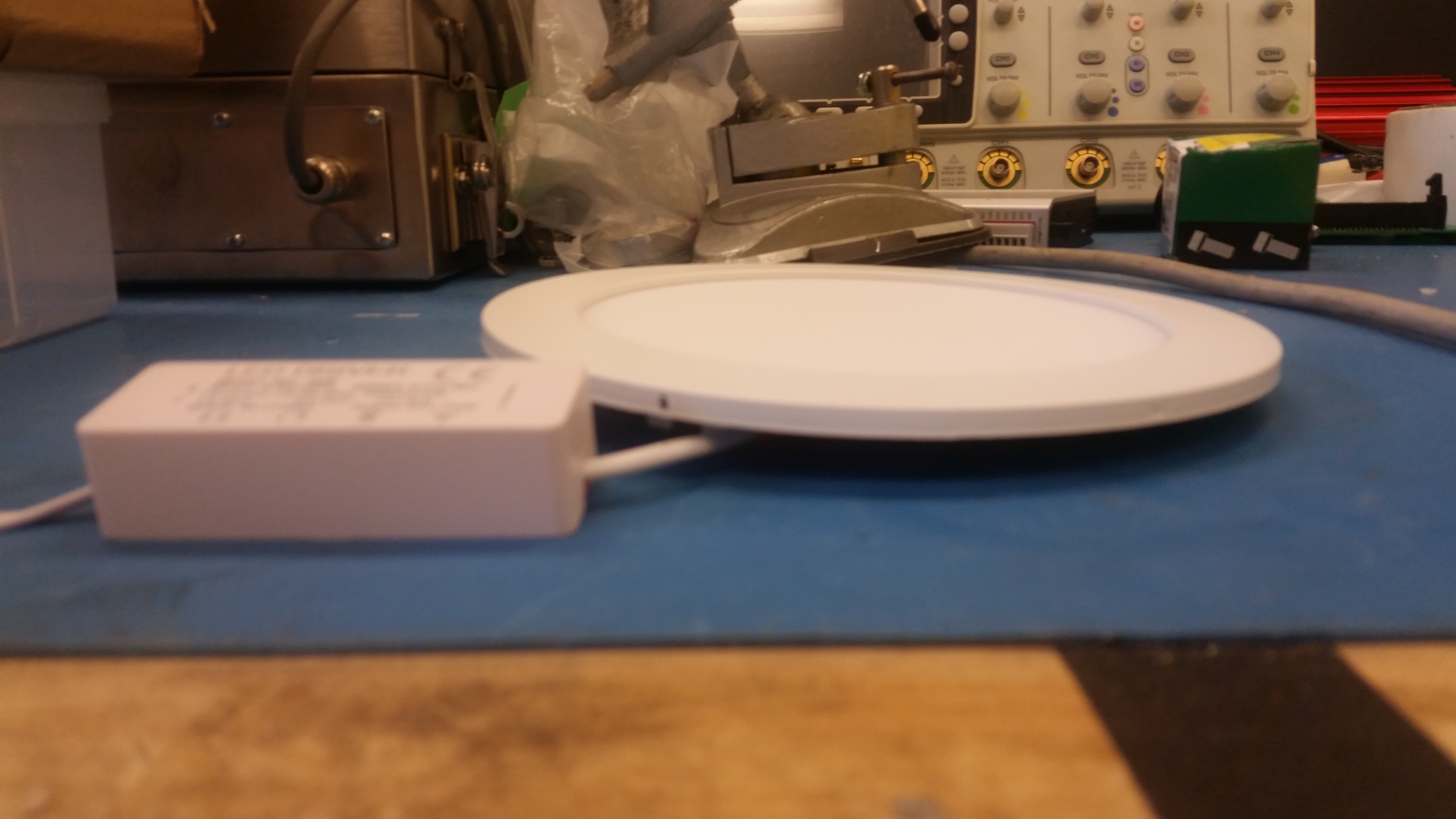 |
 |
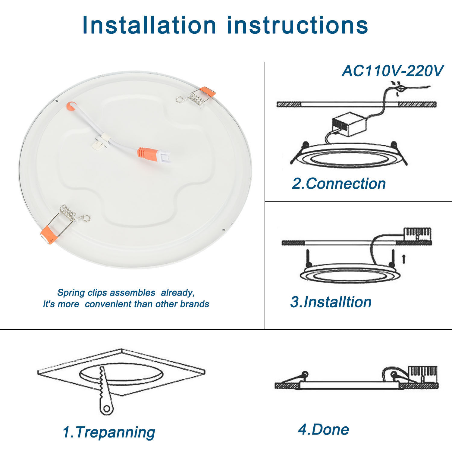
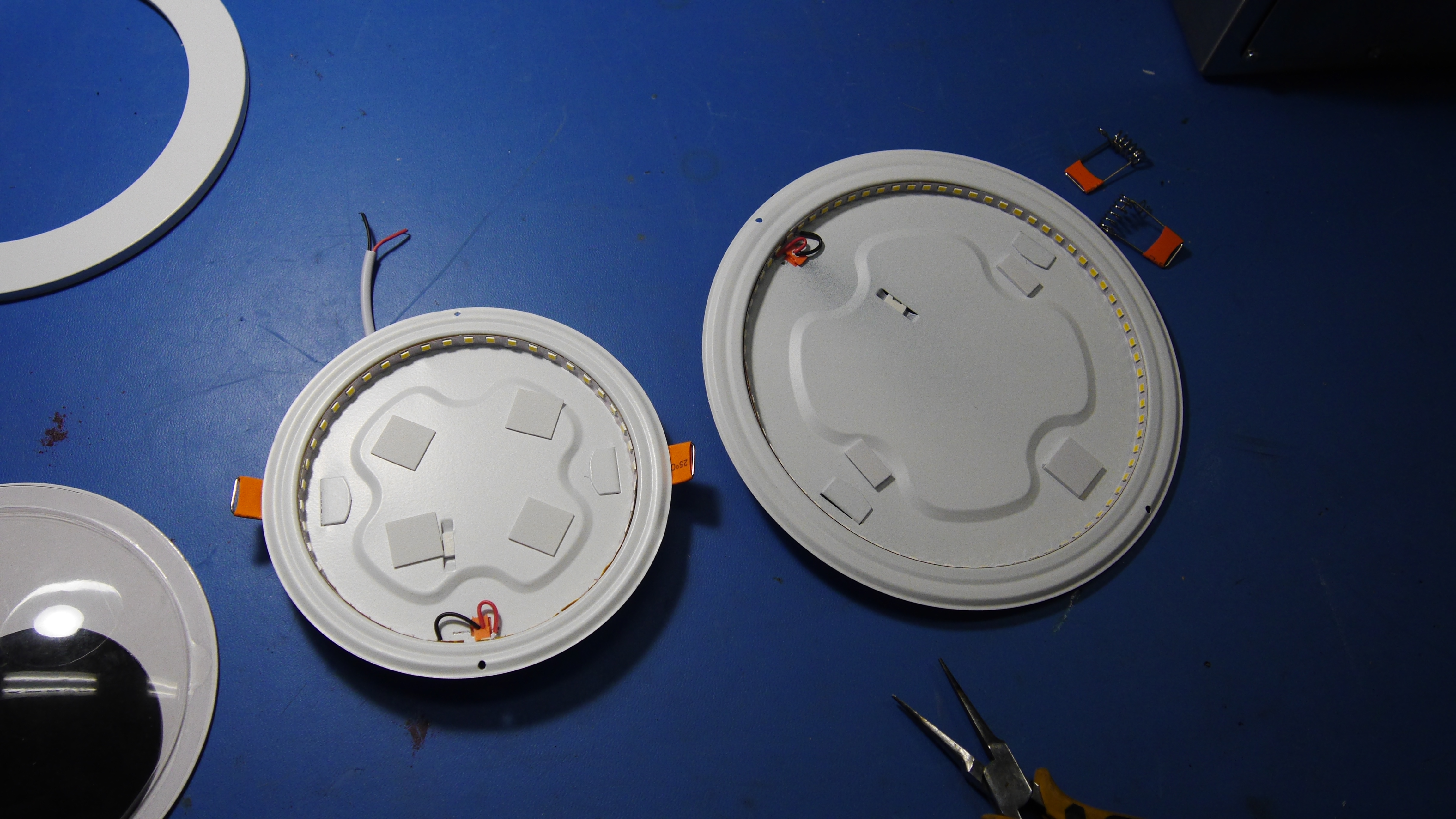
| I had orderd both the 18w 6" version and the 12w 4" version of these things. The 18w lights themselves were too big to use un-modified. The outer ring was decorative for celing installtions, just made the eyes look goofy. I began the process of opening the 18w light up to investigate how I could go about modifying it for my application. This is where i was earnestly surprised, Its just two stamped parts and an led strip. Mechanically that is it. No PCB, just a giant circular difusser. | 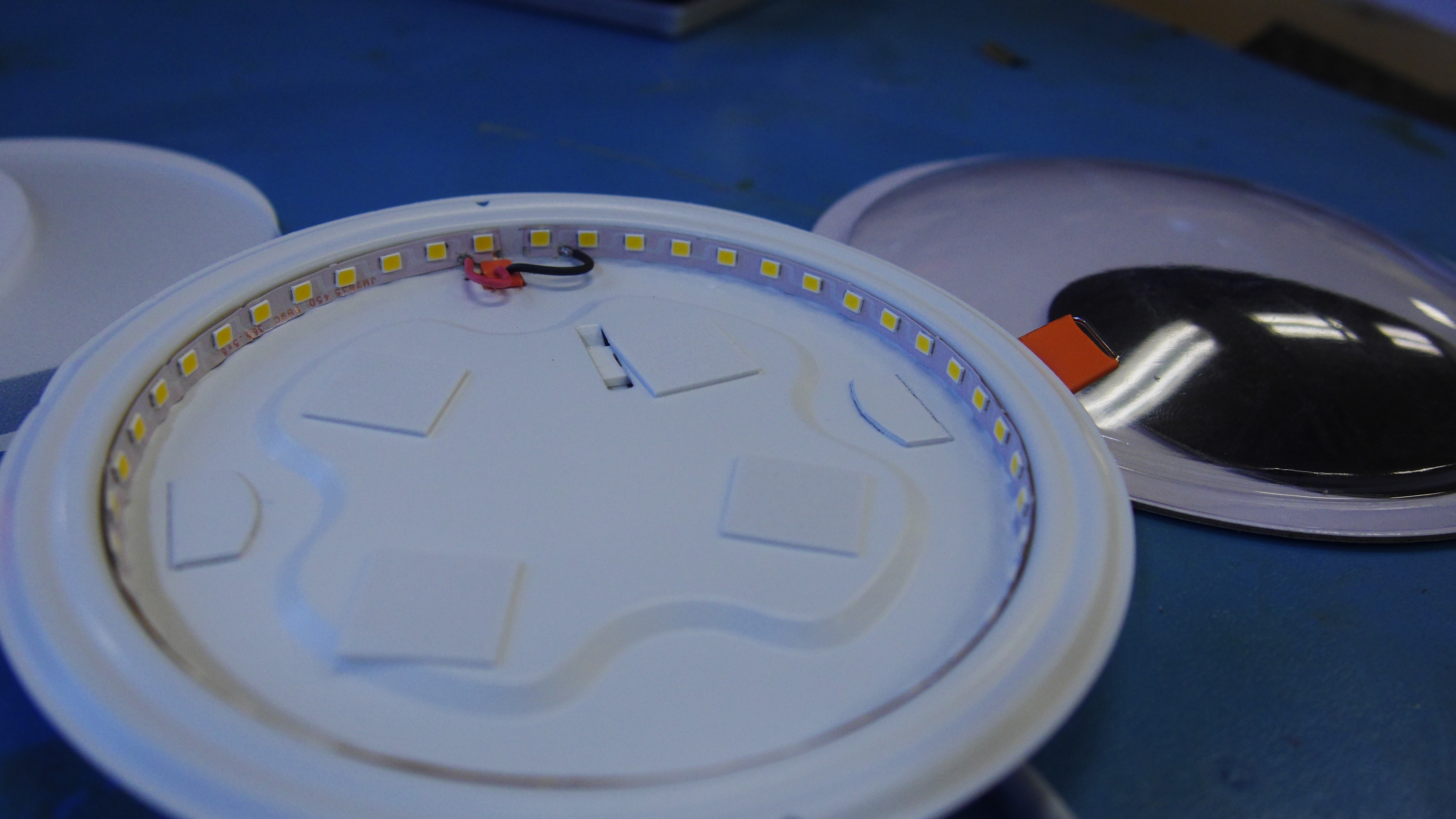 |
 |
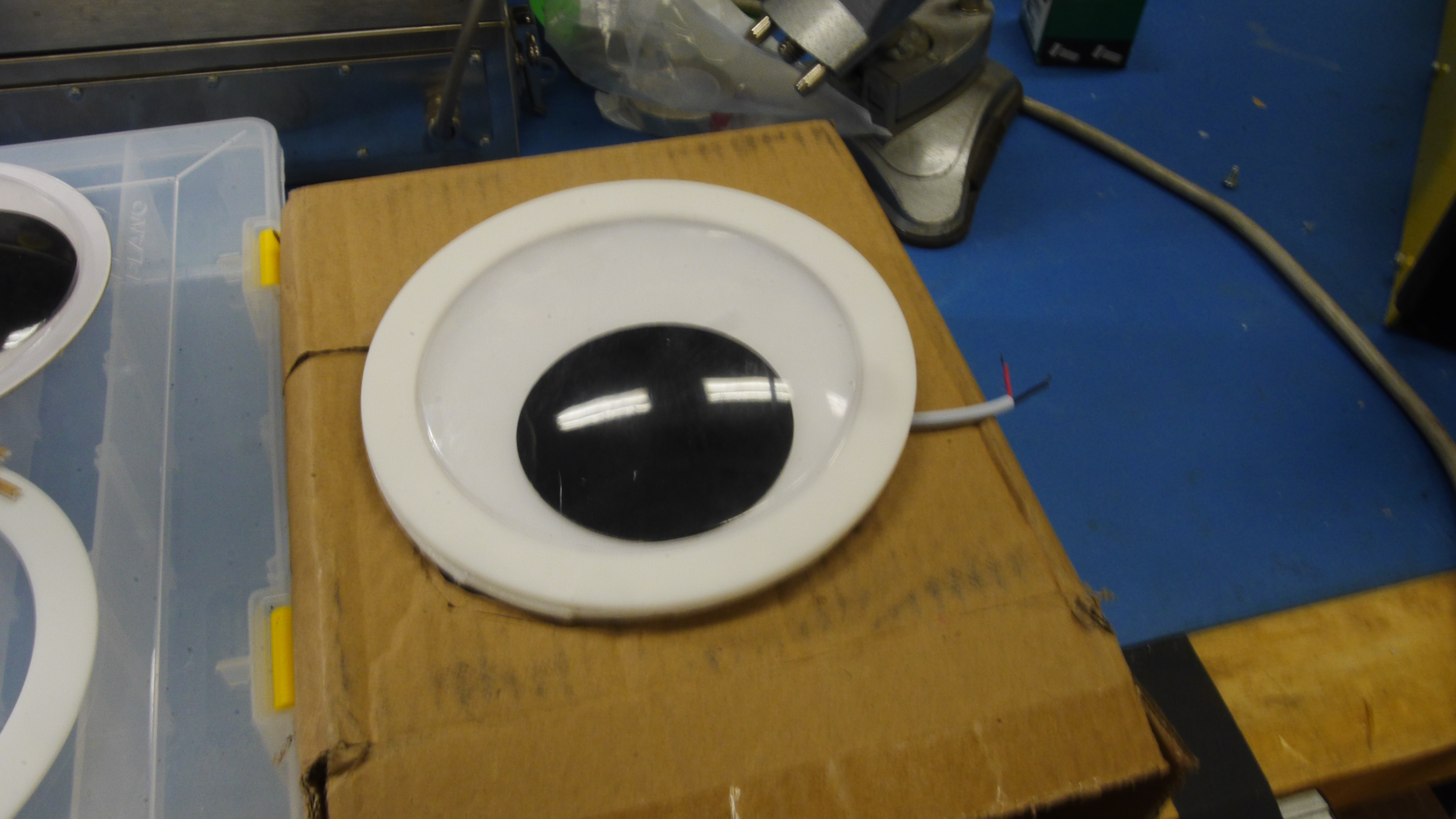
| While the design is lackluster it does fit the bill. It is bright, and impresivley evenly distributed lighting. No pointy white bits visible, just an orb of light. | 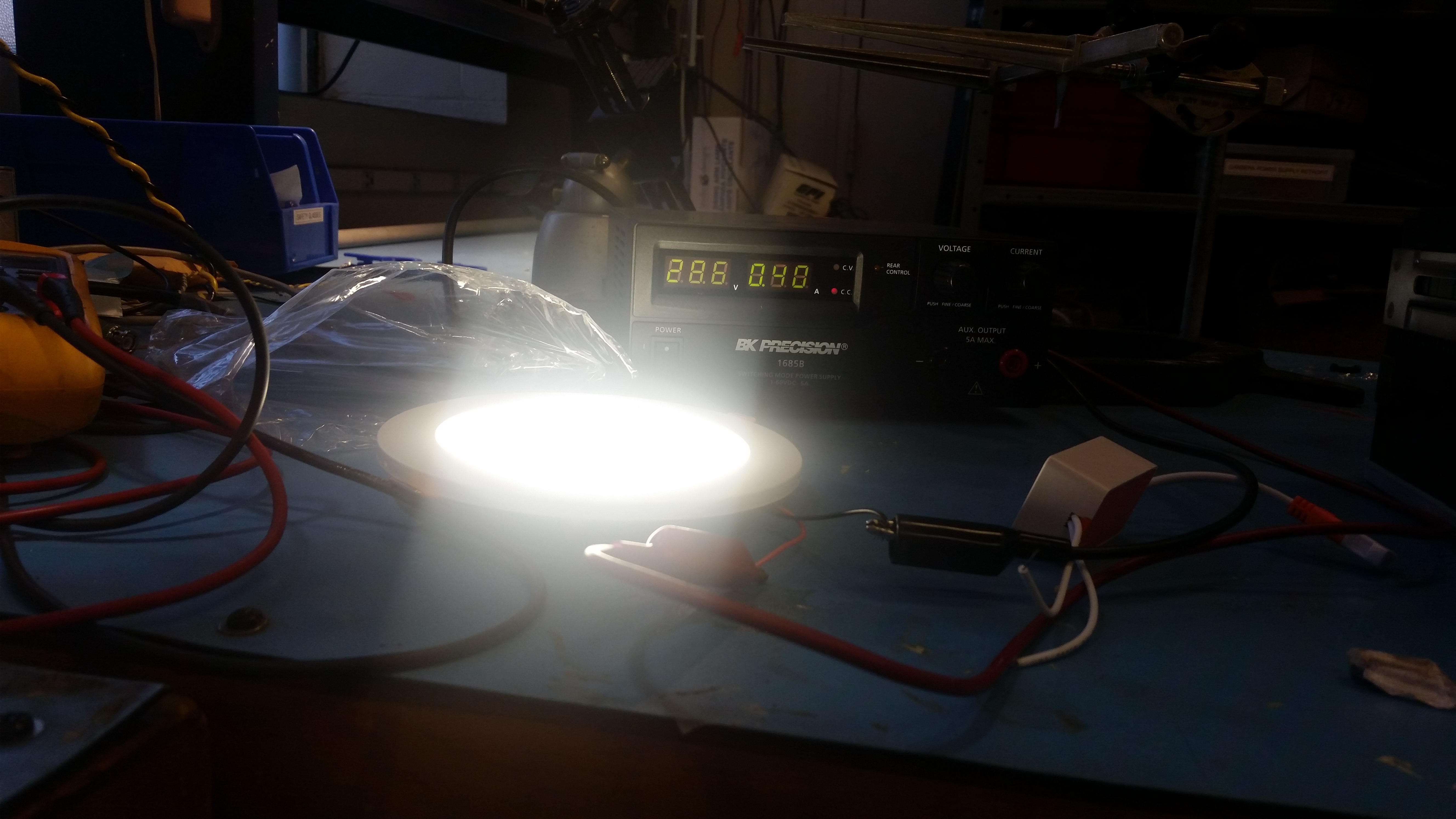 |
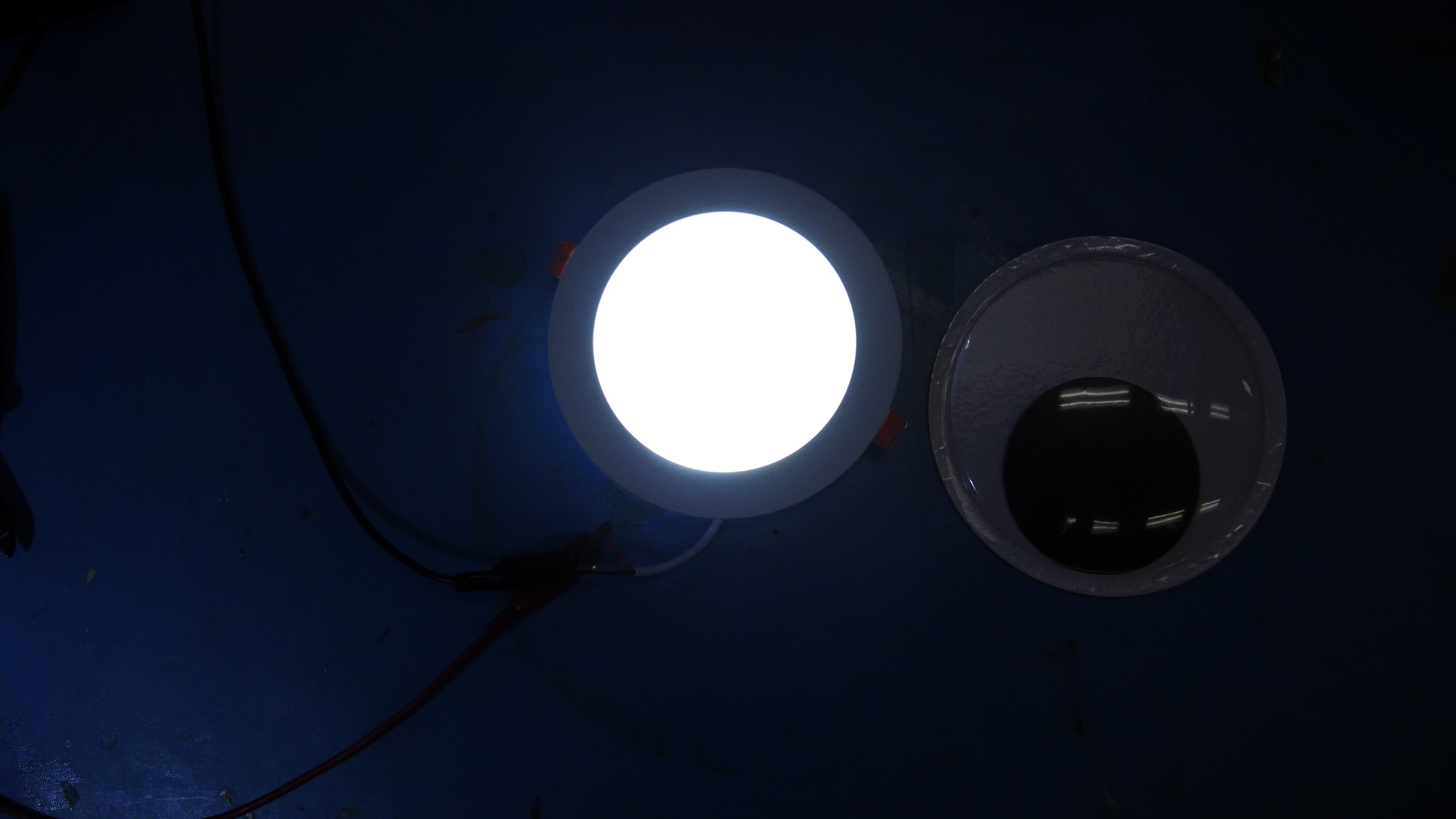 |
| As i had mentioned, the fixture alone was a bit oversized for a 6" diameter googley eye, however the actual LED strip was remarkably close in size in relation to the blow moulded googley eye cover (shown far right). | 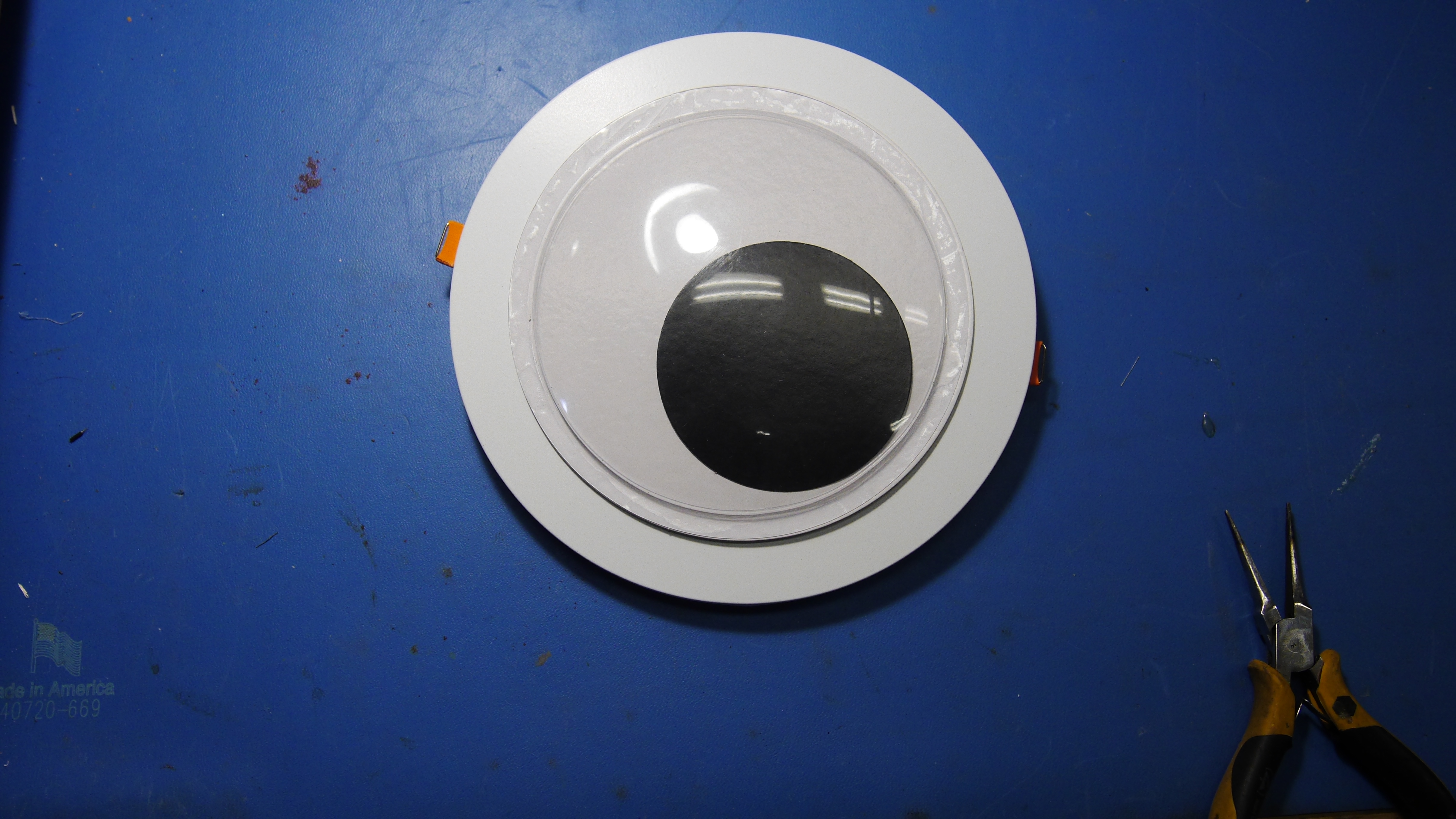 |
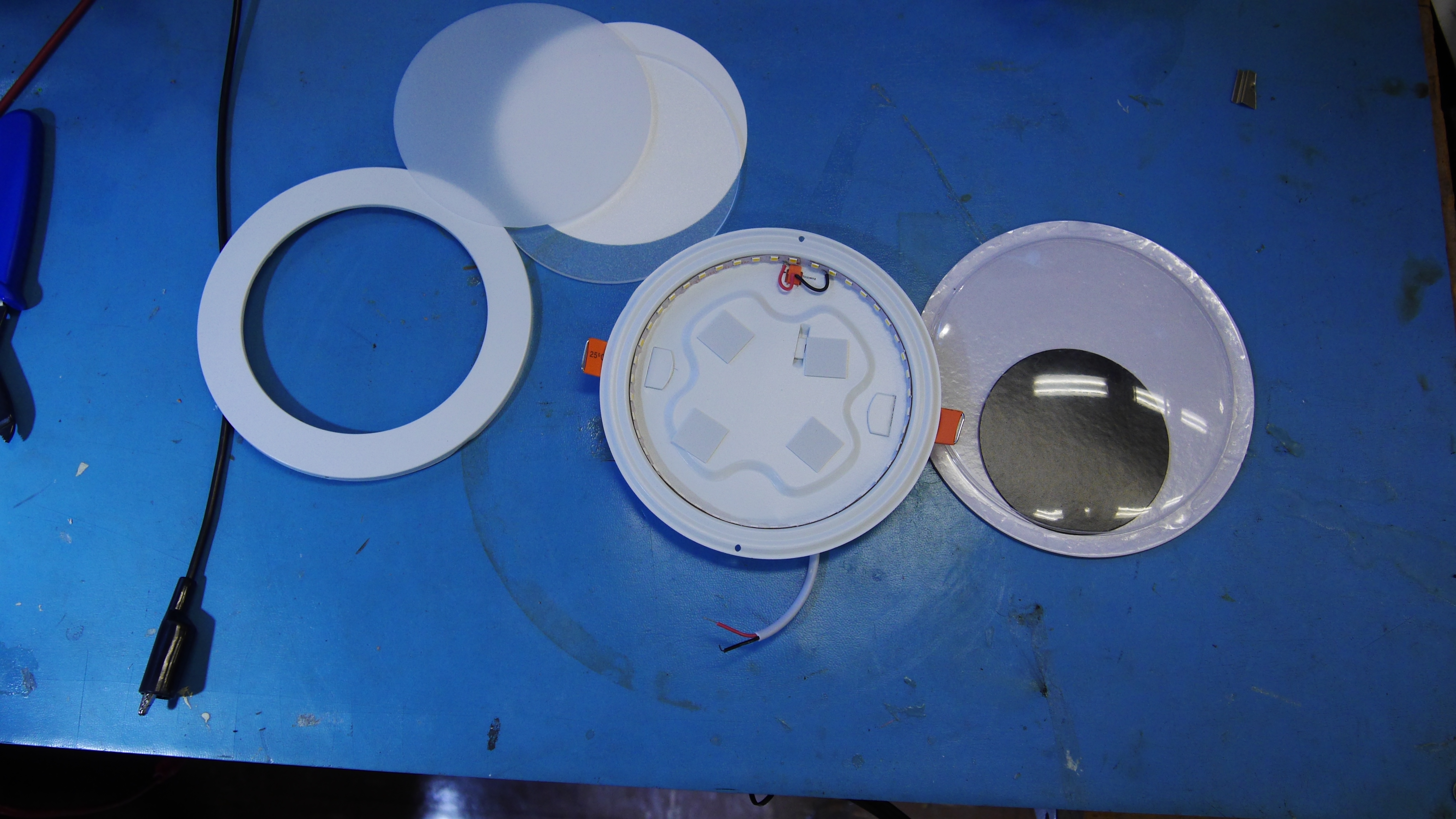 |
| Wait, how do they get the light so uniform? I didnt really pay attention here until i thought about it. There's actually 3 layers. The base is a reflective white disc. This allows the base of the actual fixture to be off-white and odd shapen. The base disc is floppy but serves as a white reflective surface. The second layer mates the light output from the leds and the outbound optic. Finally the thrid layer is a diffuser, removing any of the discrete led ring features and making the orb uniform in brightness. Without these its just a ring of leds (shown far right). | 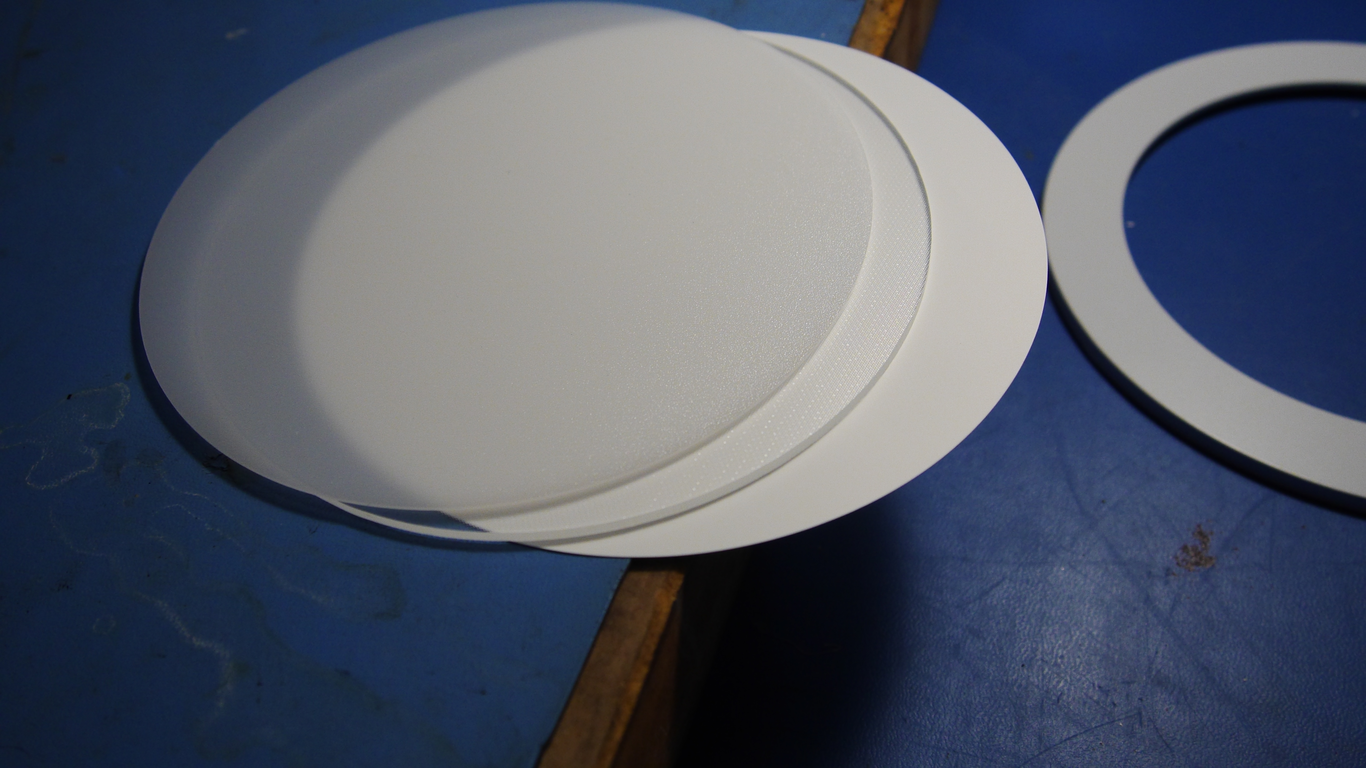 |
 |
| Some quick solidworks modeling later, I had a plan for a new enclosure for a trimmed down 18w fixture | ||
| With the model in and and DXF-ifyied, i headed to the lasercutter and cut out two sets of white acrylic 3mm googley eye-light fixture holders | 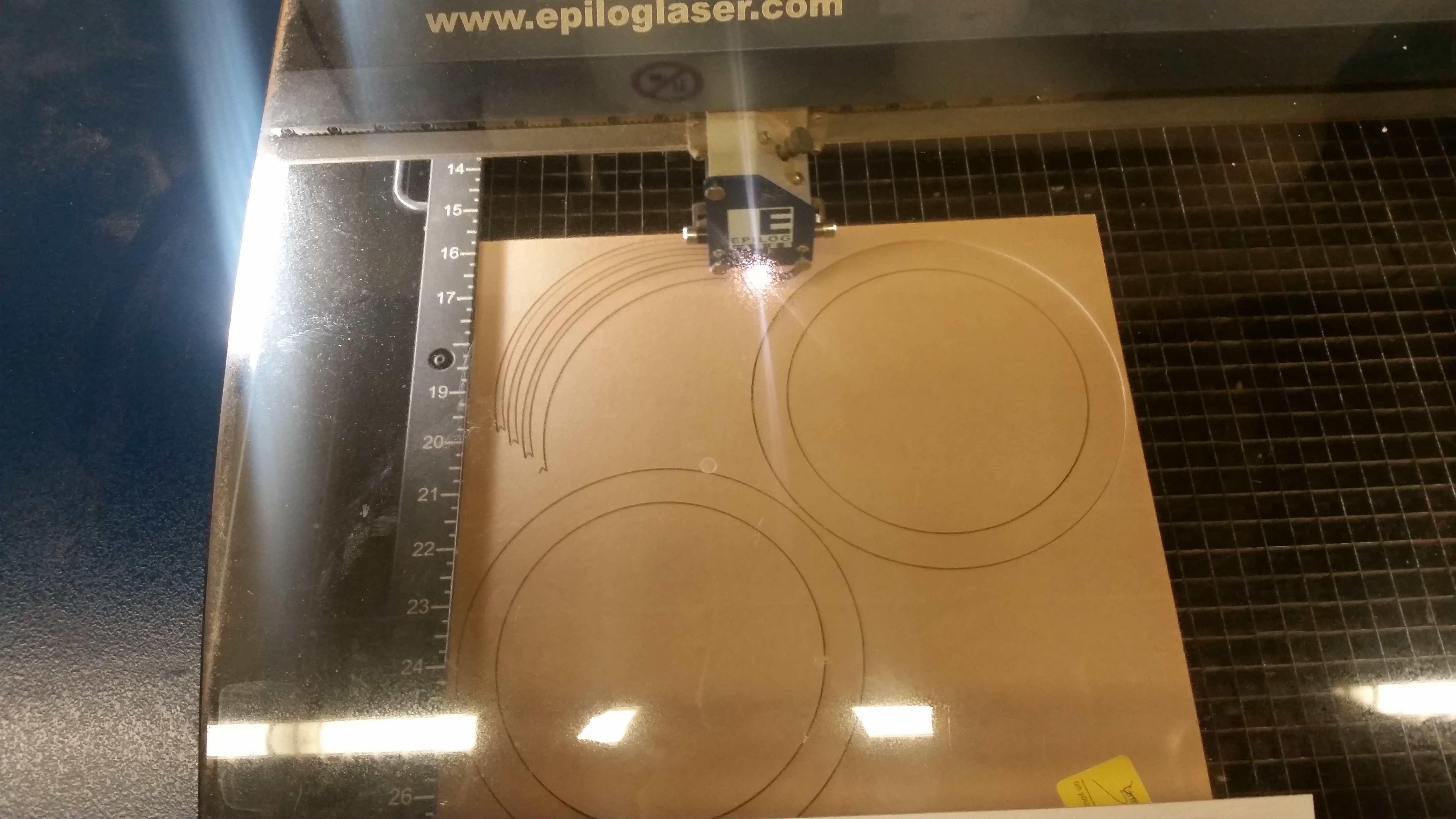 |
 |
| Laser Cutters make almost everything better. Note that this is just an abbreviated portion of the cut, sped up by 3x. I debated using acetal plastic instead of acrylic, as it is a bit more abuse tolerant, however the acrylic does solvent bond and work better with adhesives. This particular laser is a 120W epilog (CO2). Its quite a bit of laser and makes quick work of somewhat larger cuts like these. You may notice that the smaller ring around the main circle is split up into sections of three parts. Ideally i would have had a contiguous ring, however it was a bit of a waste of plastic and by opting for small 120 degree sections, i was able to fit all parts on a single ~12" square sheet of 1/8 white acrylic. |  |
| To keep everything together, acrlyic solvent bonder was used to piece together the 3-part outer ring and bond it directly to the base ring. The big base ring hold the clear portion of the googley-eye. This is RTV bonded in place to prevent moisture from entering into, uh, the google. | 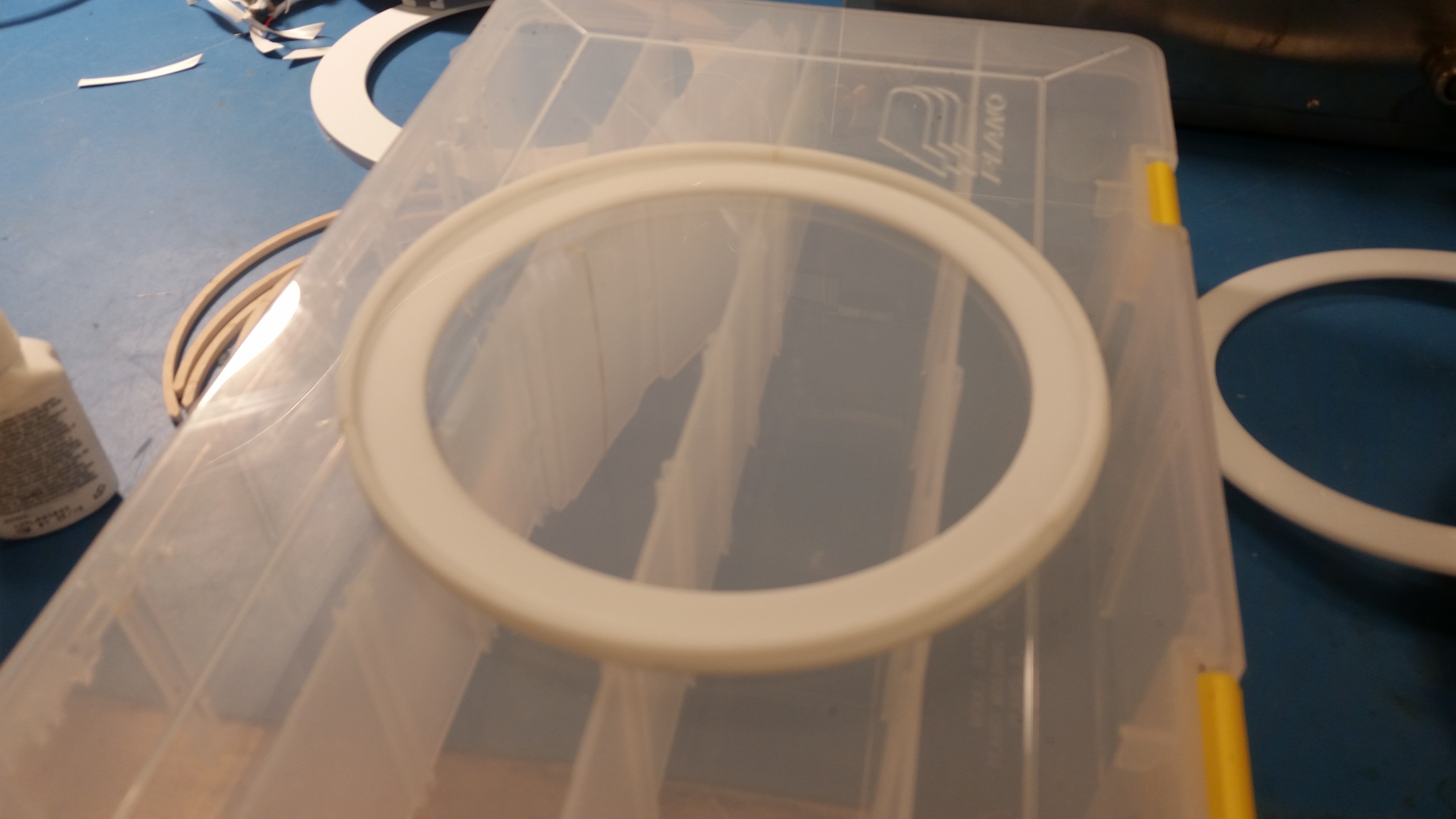 |
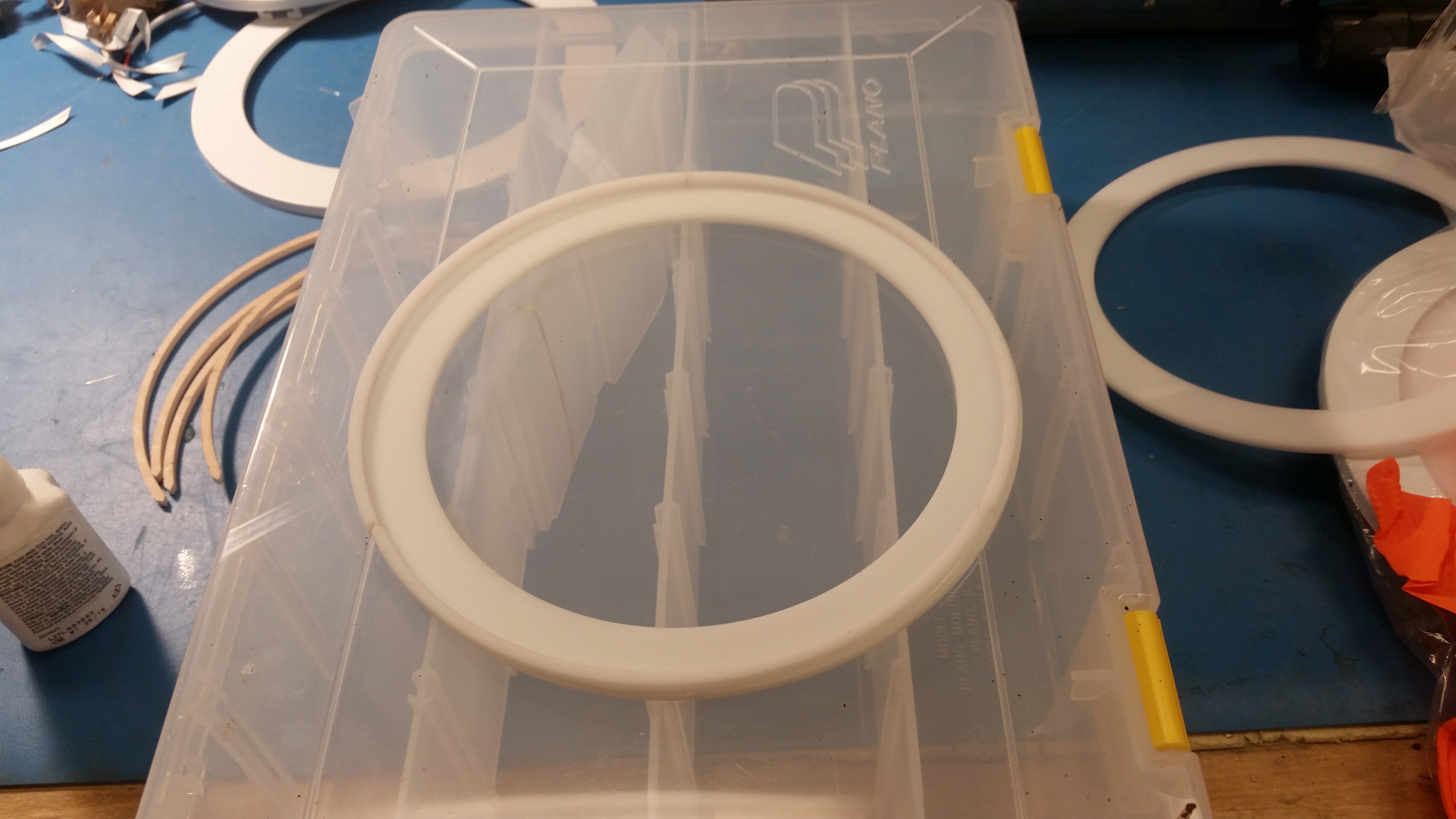 |
| To do the RTV gluing, the acrylic holster sat on top of a shallow cardboard box. The box itself had a hole cut out of the middle so that the googley eye could rest below the surface. the blac dot in the middle of the googley eye sat resting up against the clear part of the google. After letting the RTV set for a bit, it was time to mush the trimmed down light fixture in place. | 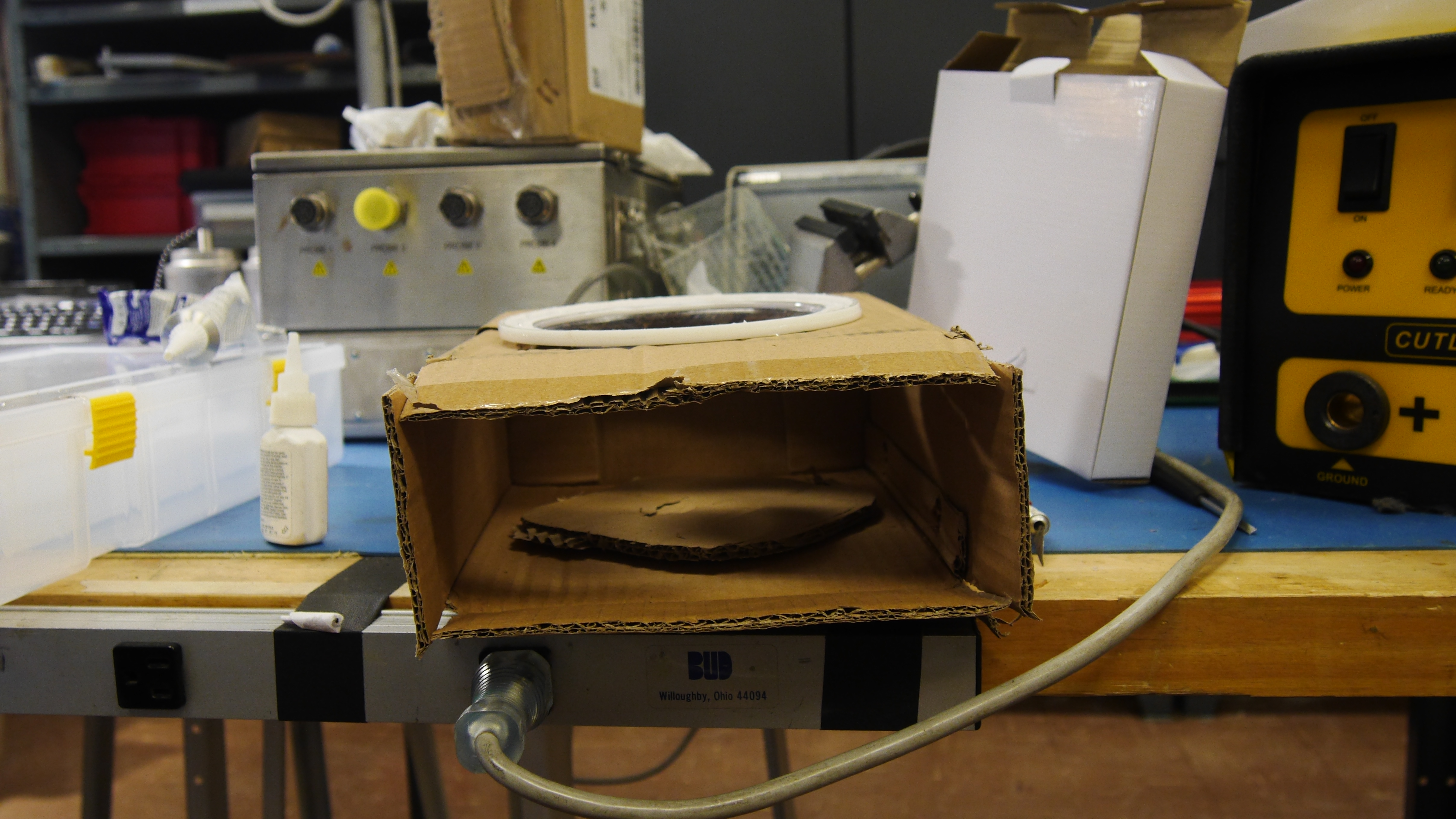 |
 |
| It was a 'realy tight clearance fit', and after some struggling the trimmed down light fixture now mated to the googley eye acrylic holster. A hefty bead of RTV then mated the light fixture to the acrylic holster. This should be sufficient to keep out moisture and hold everything together, but its something that i will try and keep an eye on. Oh dear. | 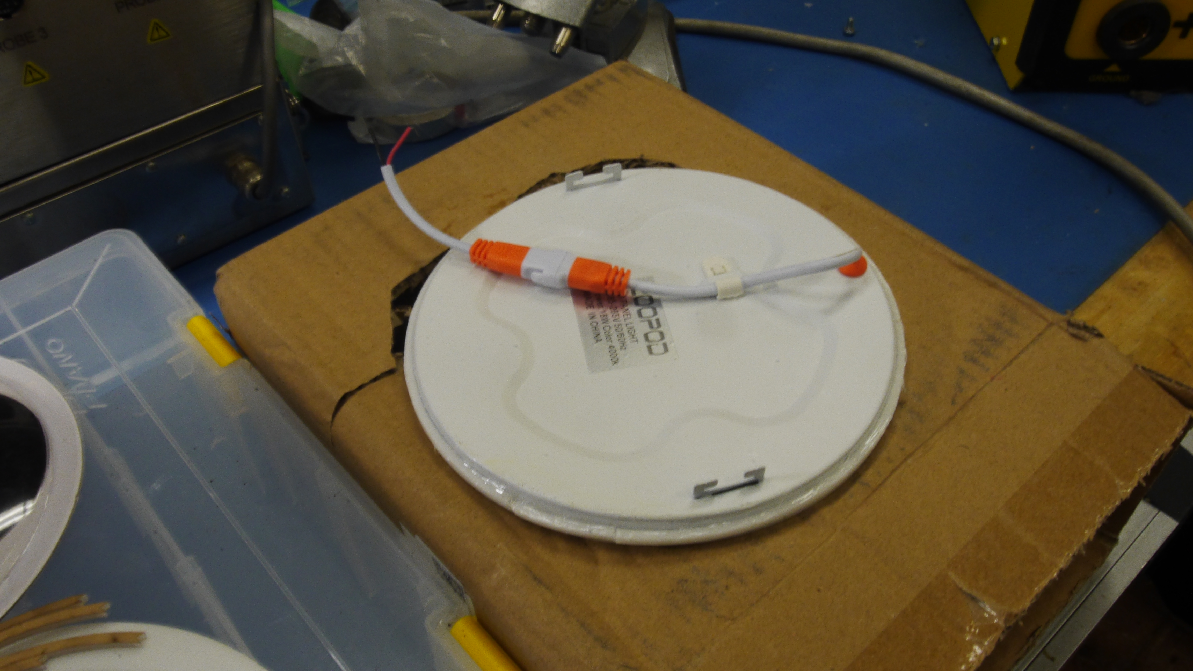 |
 |
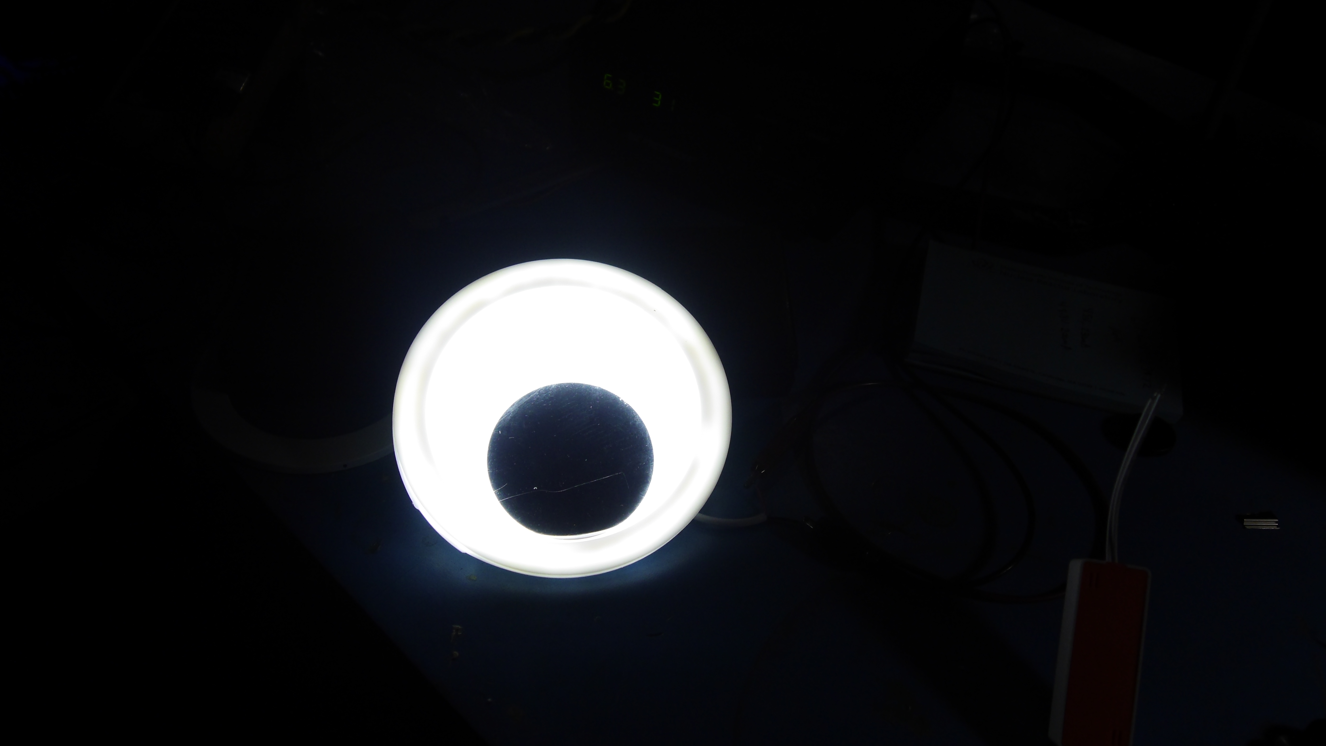
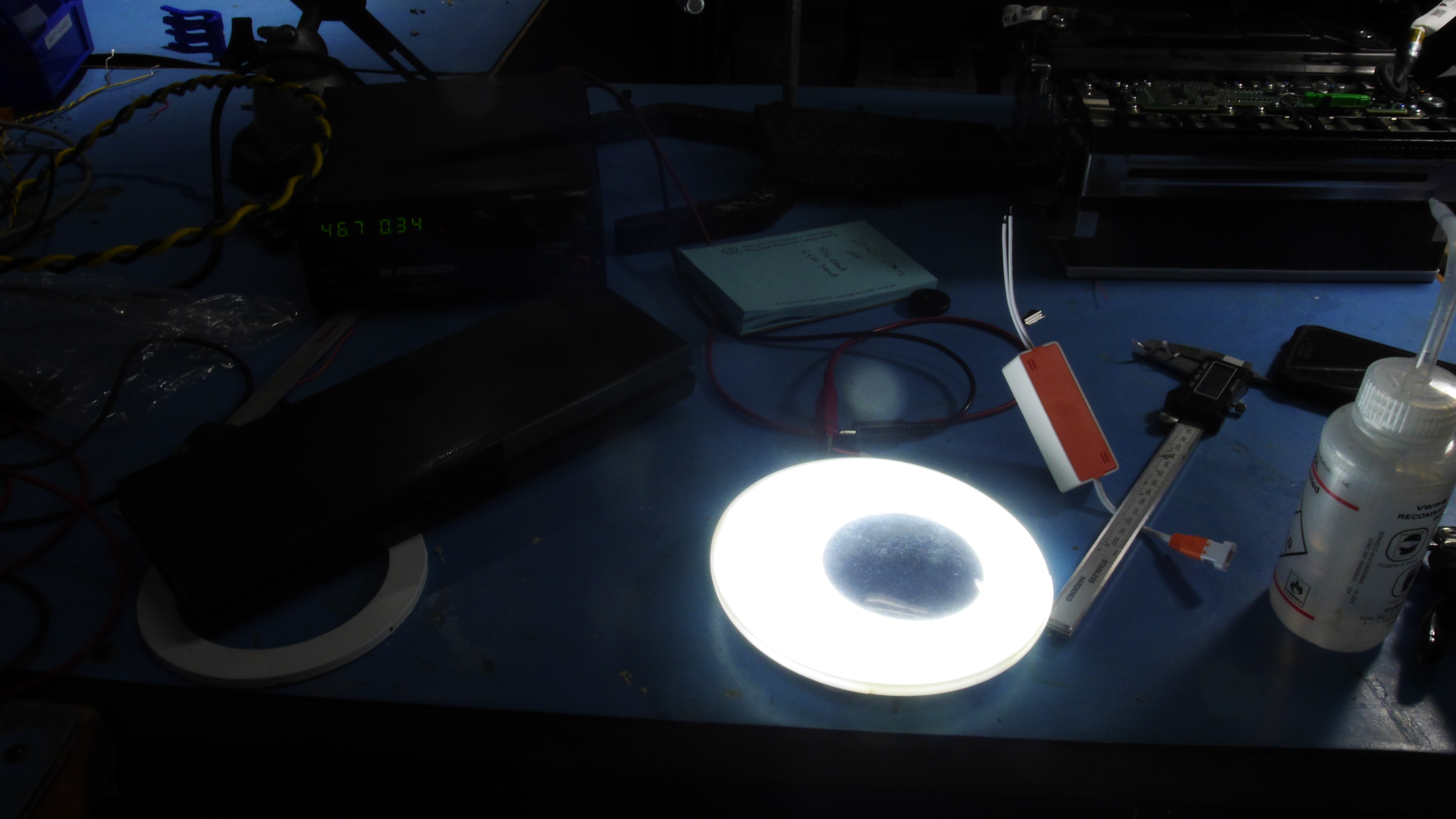
| With
the respective glues set, time to see if everything still works. I used
a power supply with the current limit set to ~200mA (theoretically
rated for 400mA but I really didnt want to have to re-make this thing.
It was quite bright even in a well lit room. Ok this is gettingf
exciting |
 |
 |
| Next up is how to hold the new covert headlight eyes. Off to solidworks again. I was fortunate to still have my cad files from the previous year handy |
| Waterjet Time! This particular jet is an OMAX MiroMax. It loves fine detail, but it has a limited traverse speed. For thin materials like this (0.1") the cutting speed is basically the traverse speed. The animation (right) is shown sped up significantly, but out from the scrap sheet appeares two mounting brackets! |  |
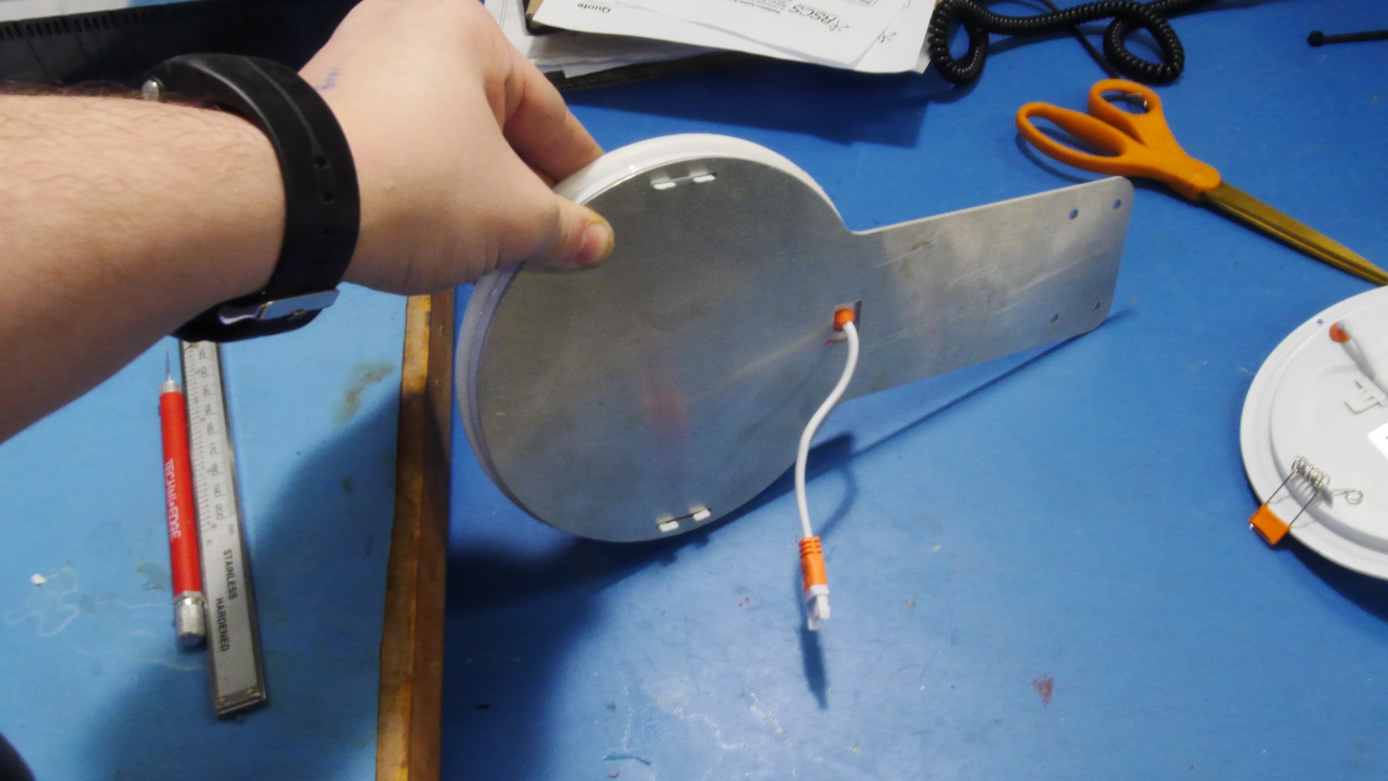
| From the waterjet we get the two identical (0.1" thick) 6061 aluminum googley eye holsters. These were a fairly quick cut (6 min total), and should have the same mounting setup as last years plastic mounts. To make sure everything lined up i made 1:1 printouts on paper and double checked dimensions with the light fixture cutouts. The square hole allows the grometted light cable to pass through and the two slots allow for the tabs to pass through as well. Shown far right is the paper version used as a mockup. | 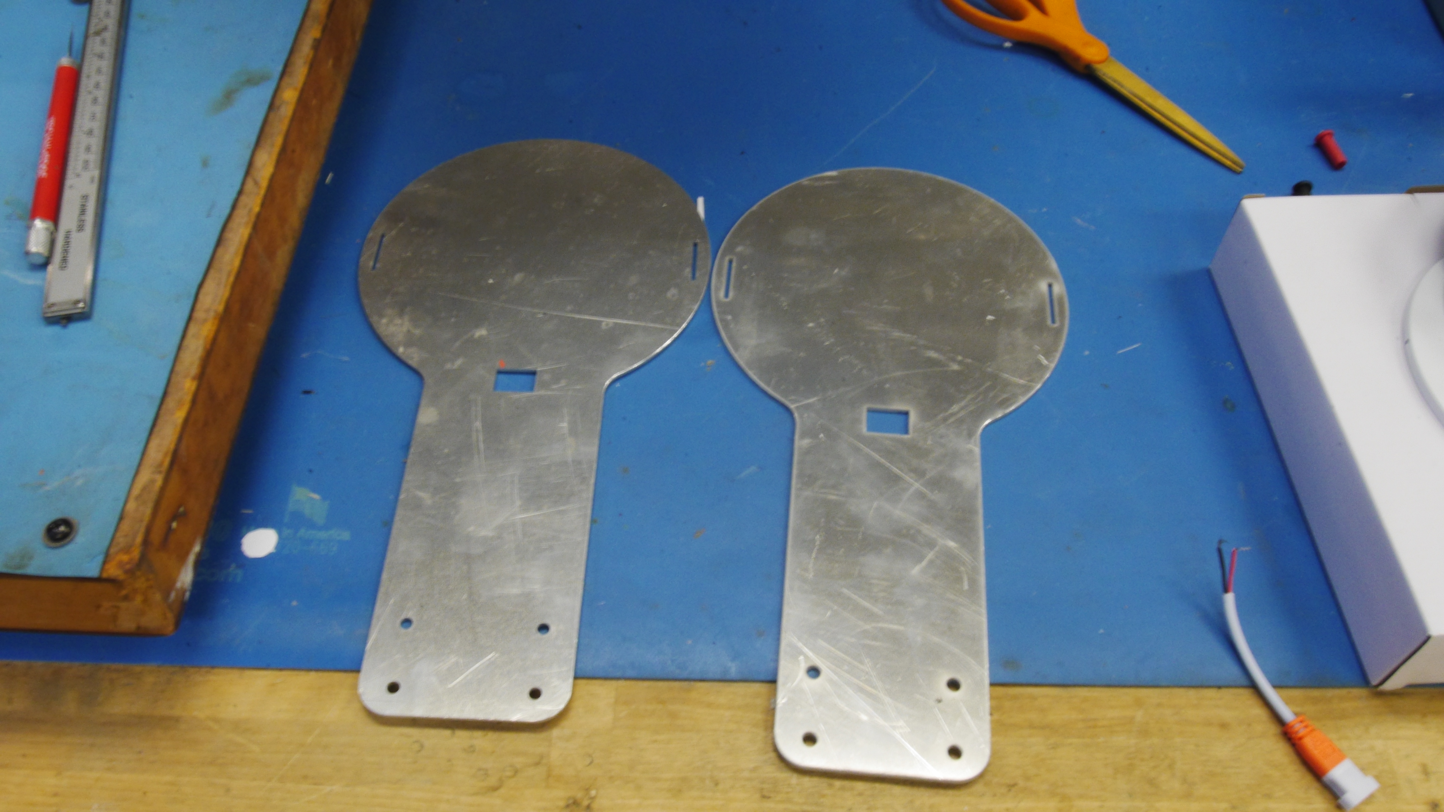 |
 |
| There's this wonderful feeling when parts just fit. Everything lined up and lo there was a new headlight holder. | 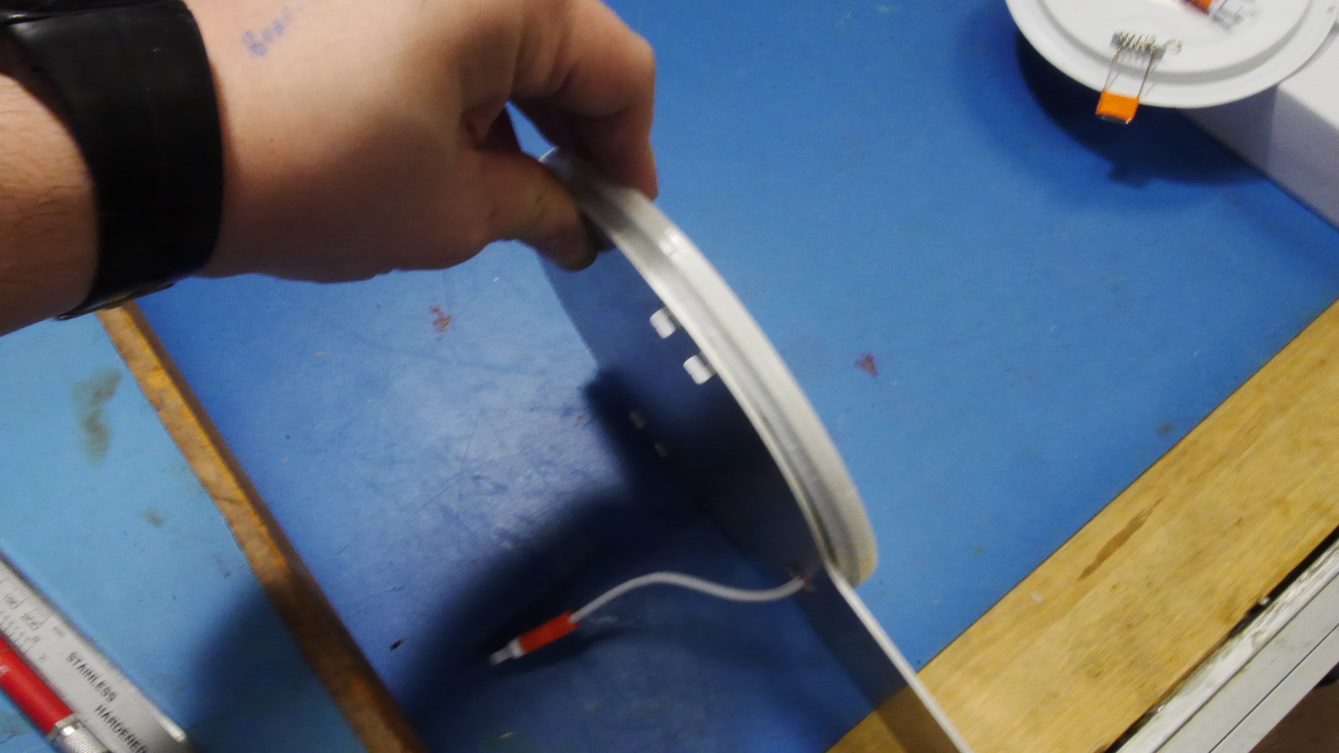 |
 |
| I didnt use anything incredibly precise to bend the aluminum brackets, just a vice and some precision hand-movements. I took some time to scour the surface to give the upcoming spraypaint a better chance of bonding to the aluminum. | 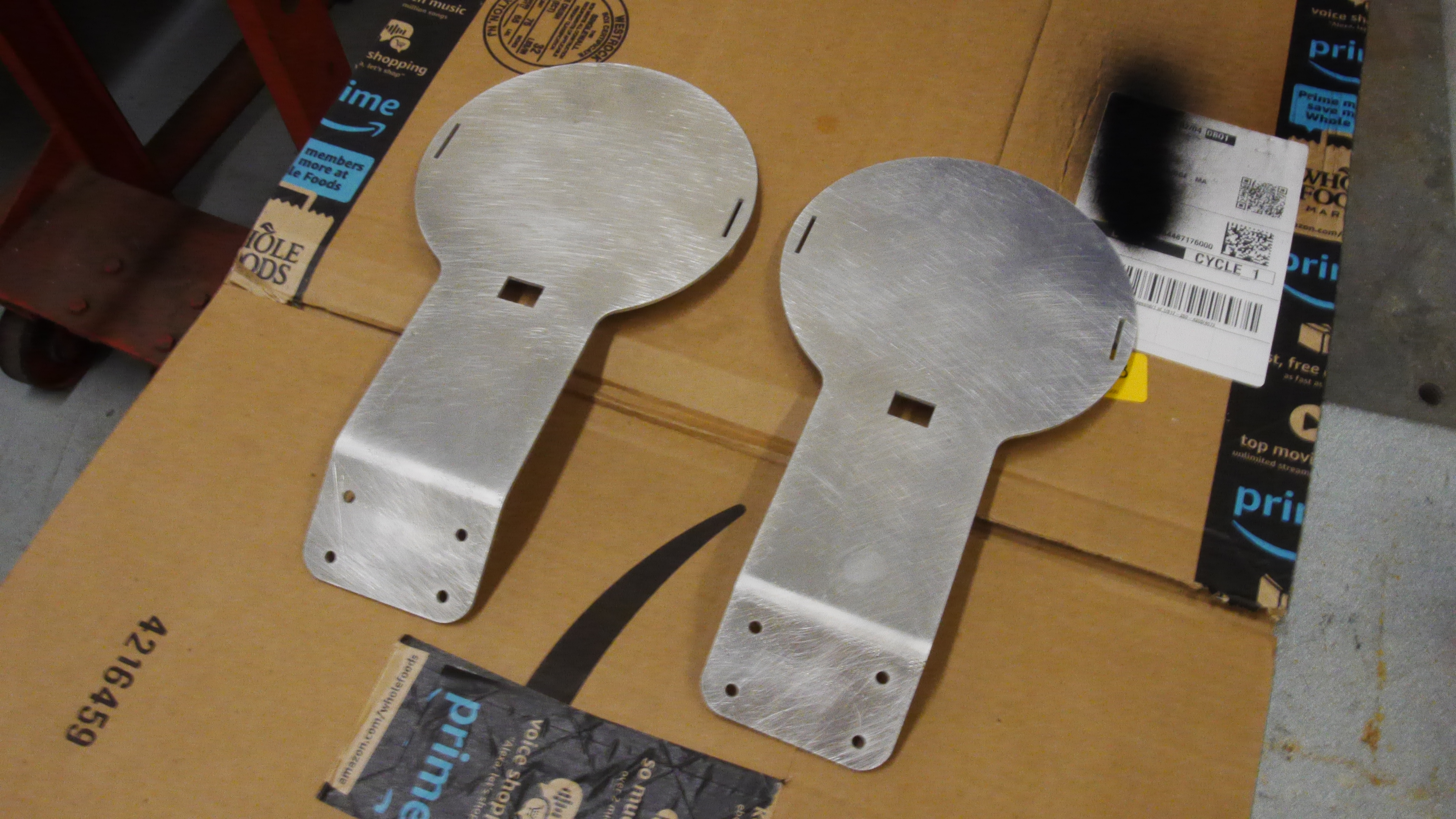 |
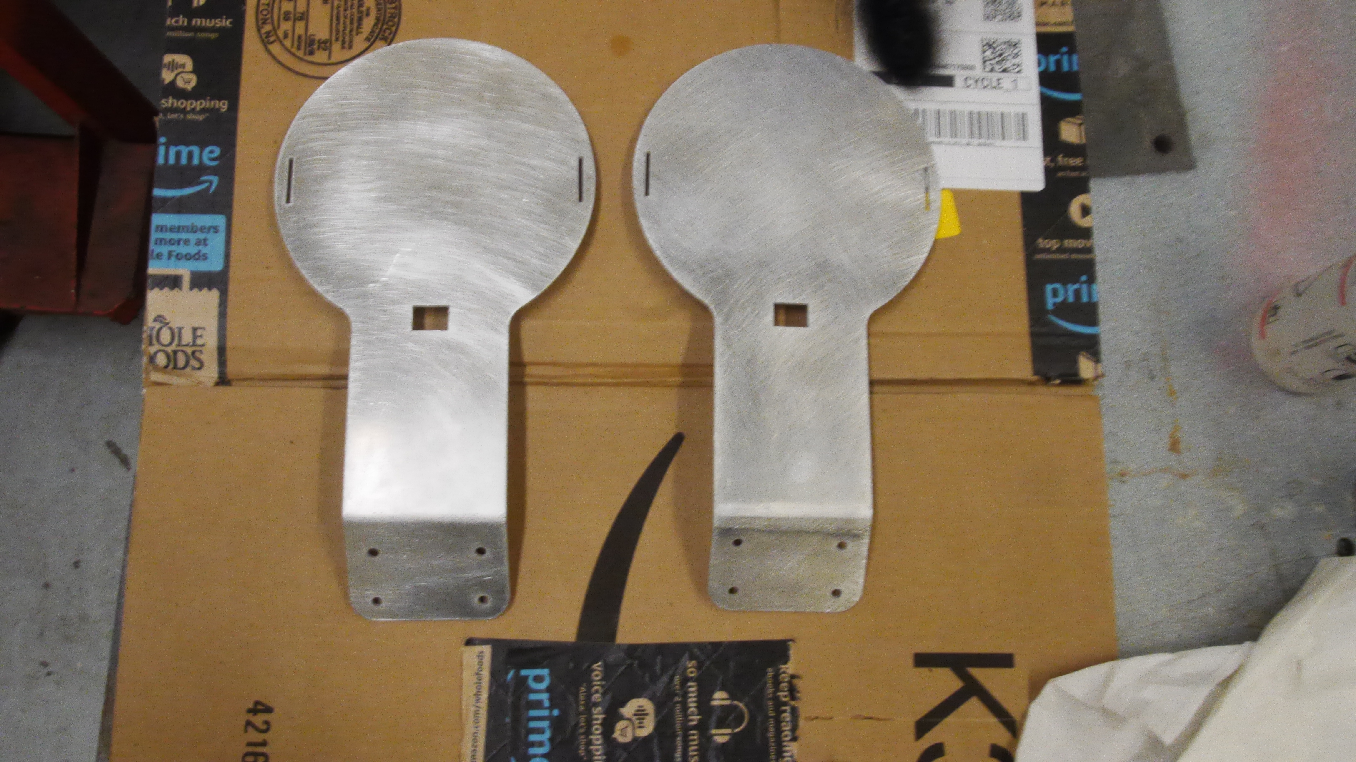 |
| I taped off the side that the googley eye light would attach to, in case i wanted to reinforce it with double sided tape / rtv. Everything else was coated with black krylon spray paint | 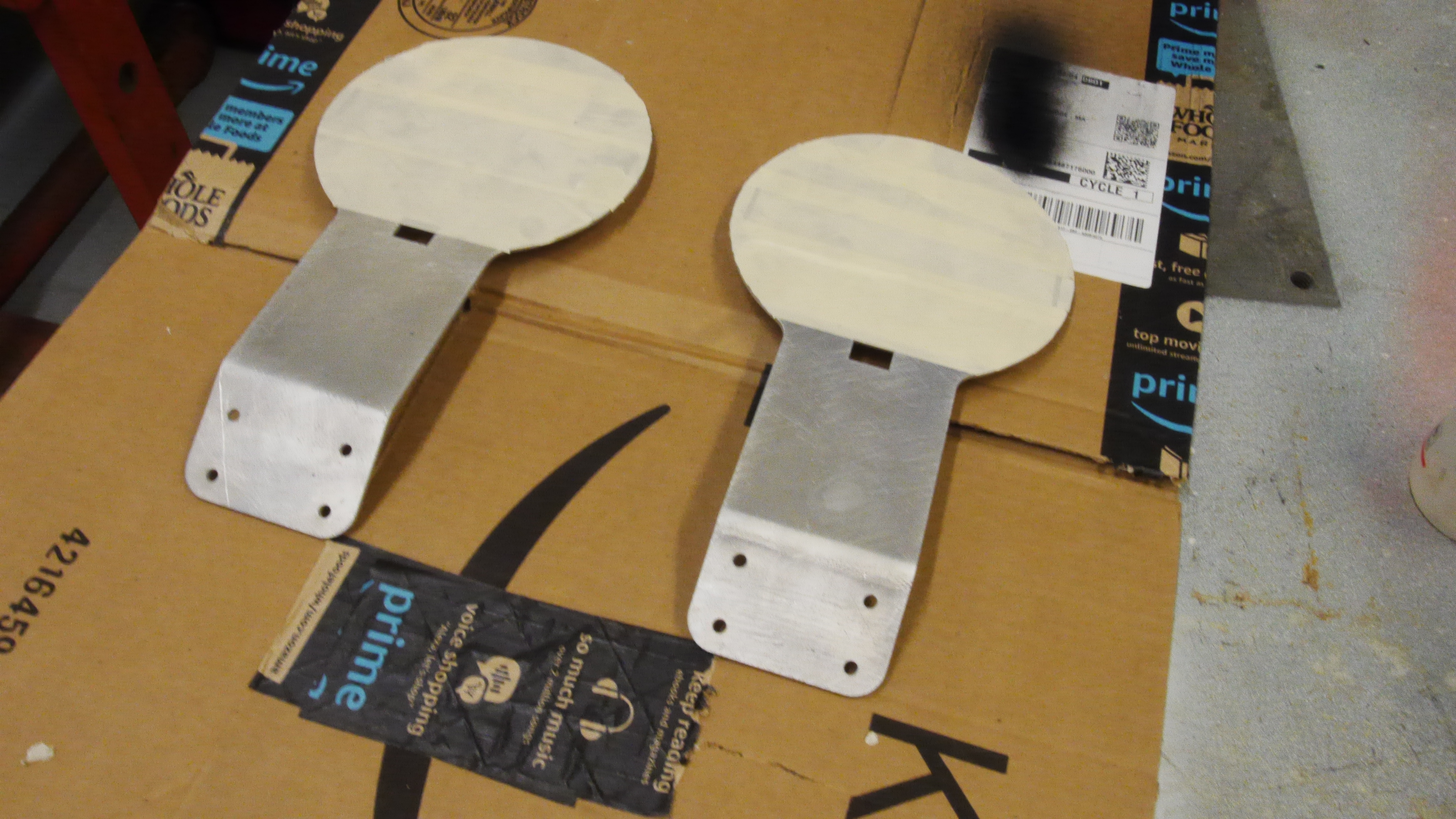 |
 |
| Everything came out great, the googley eye lights snapped right into place and the small metal folds held the fixtures right up to the new aluminum holsters without trouble. | 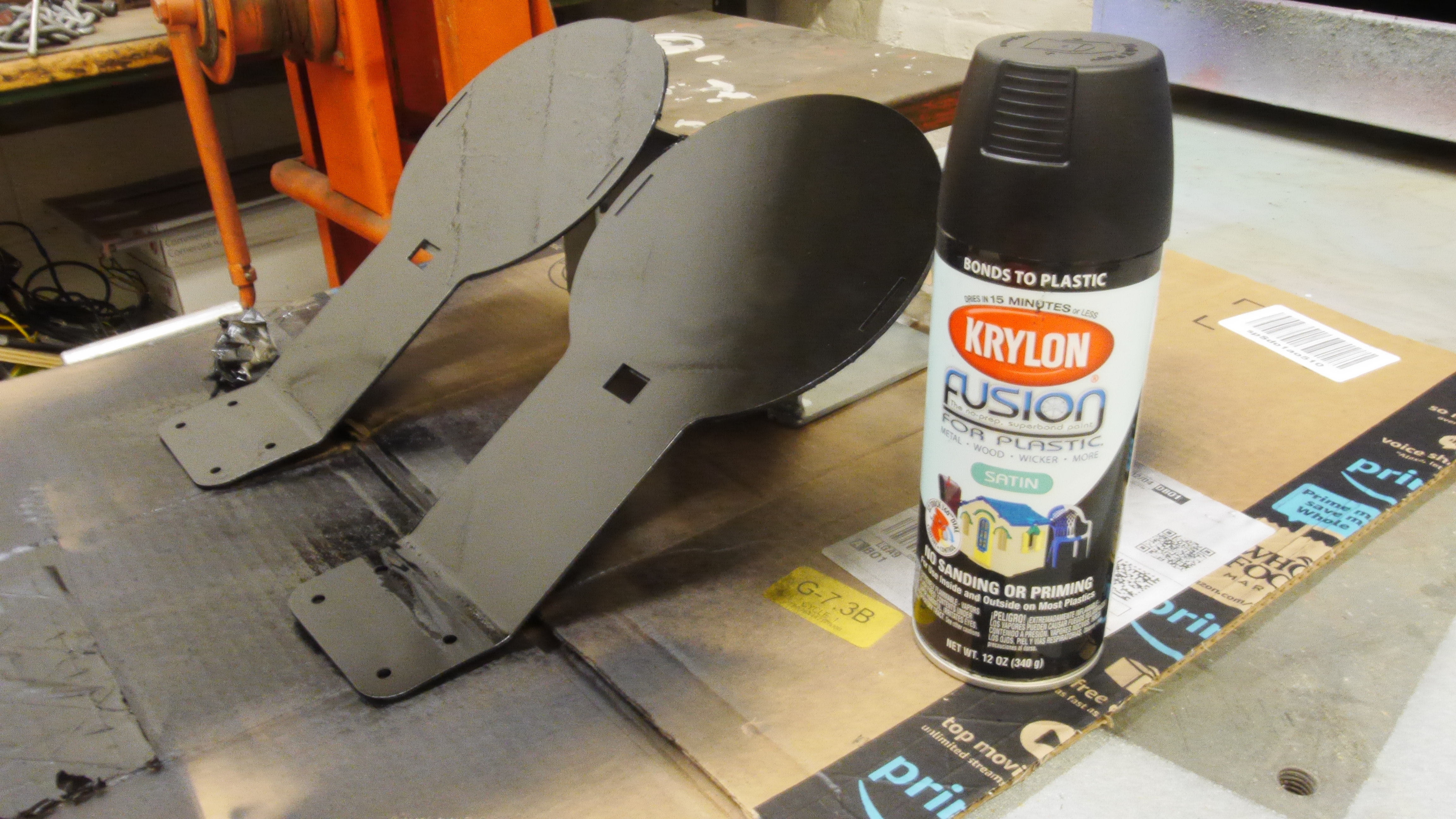 |
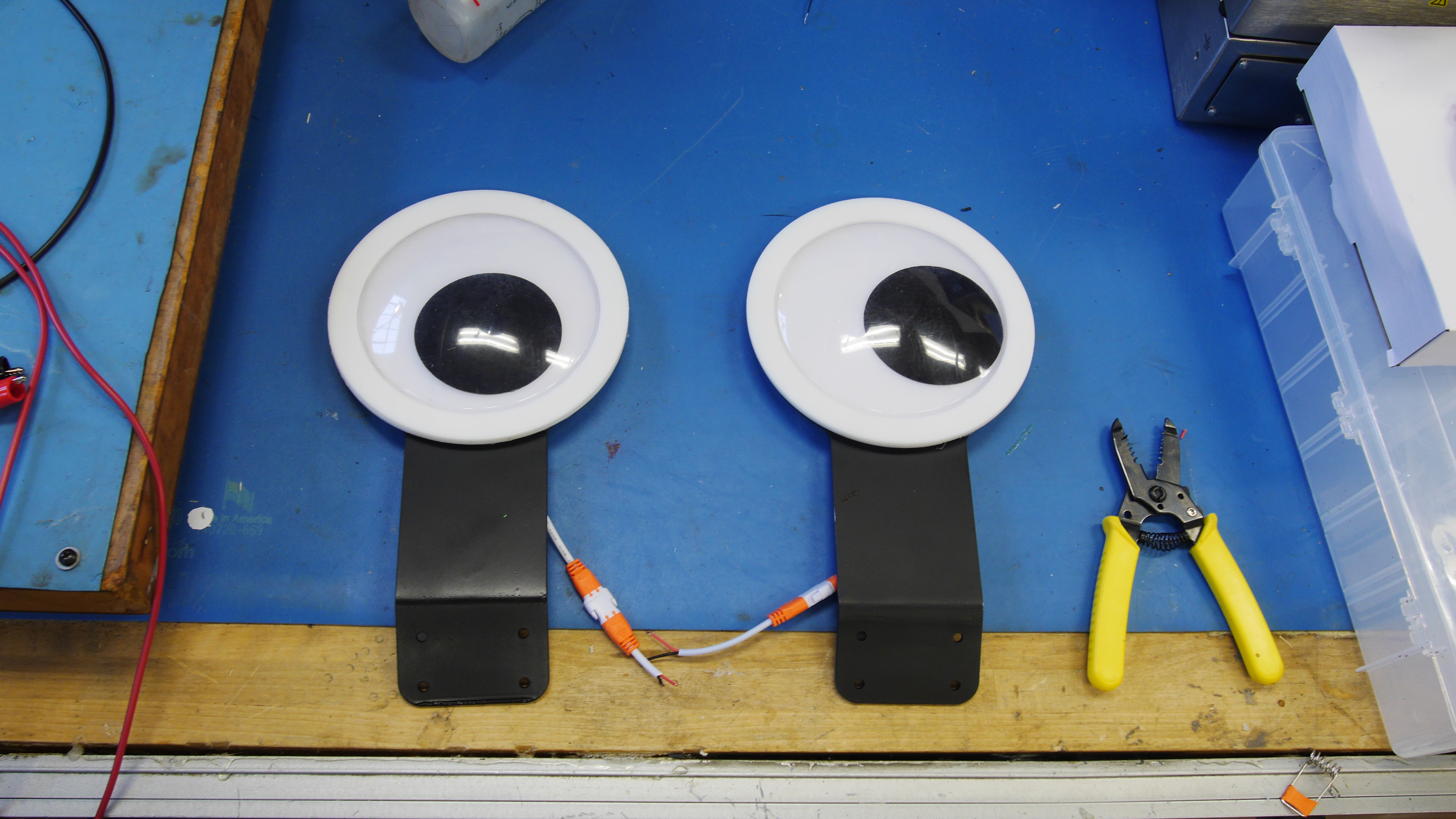 |
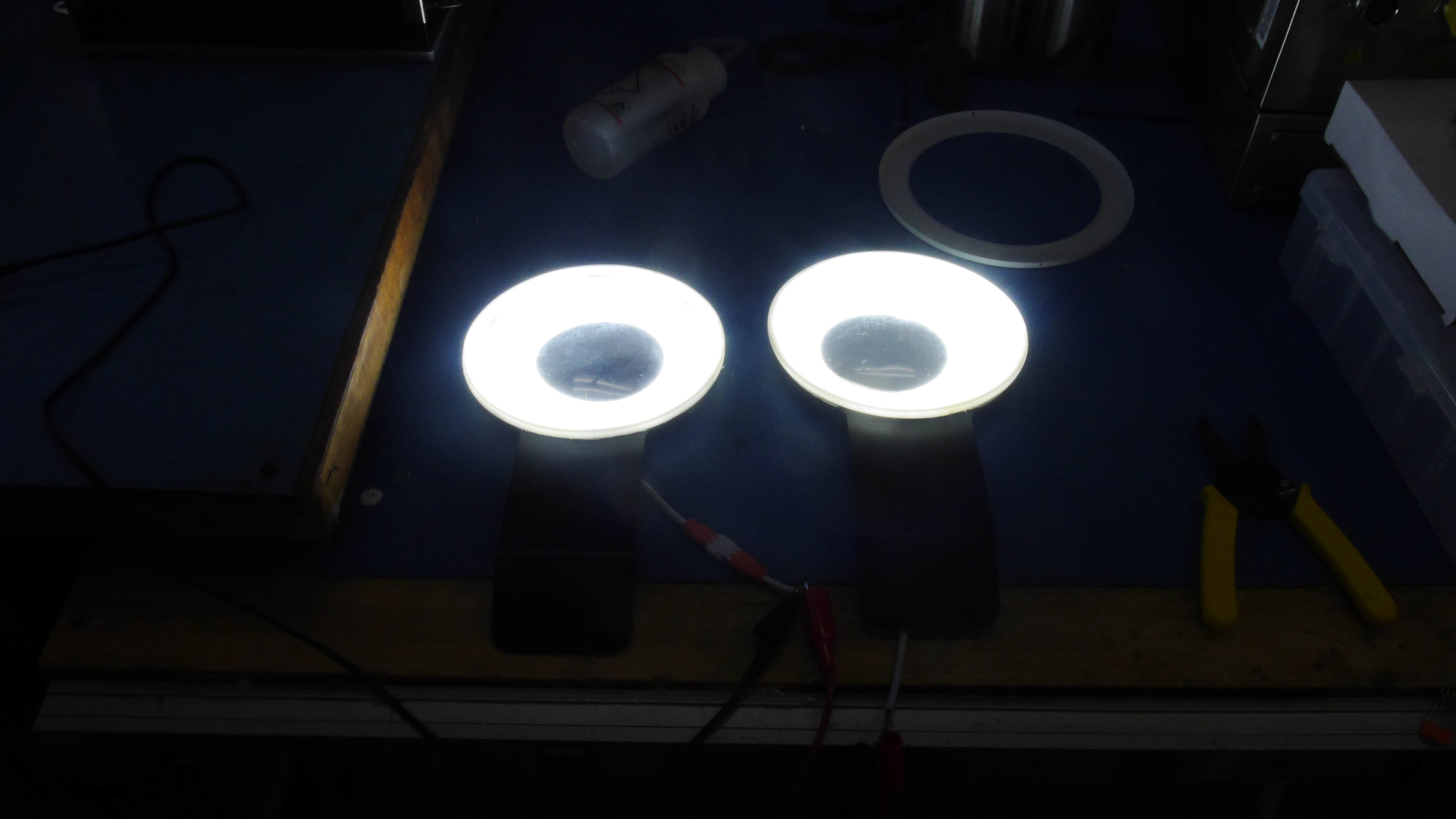
| These images were taken in a normally well lit room, they are quite bright! | 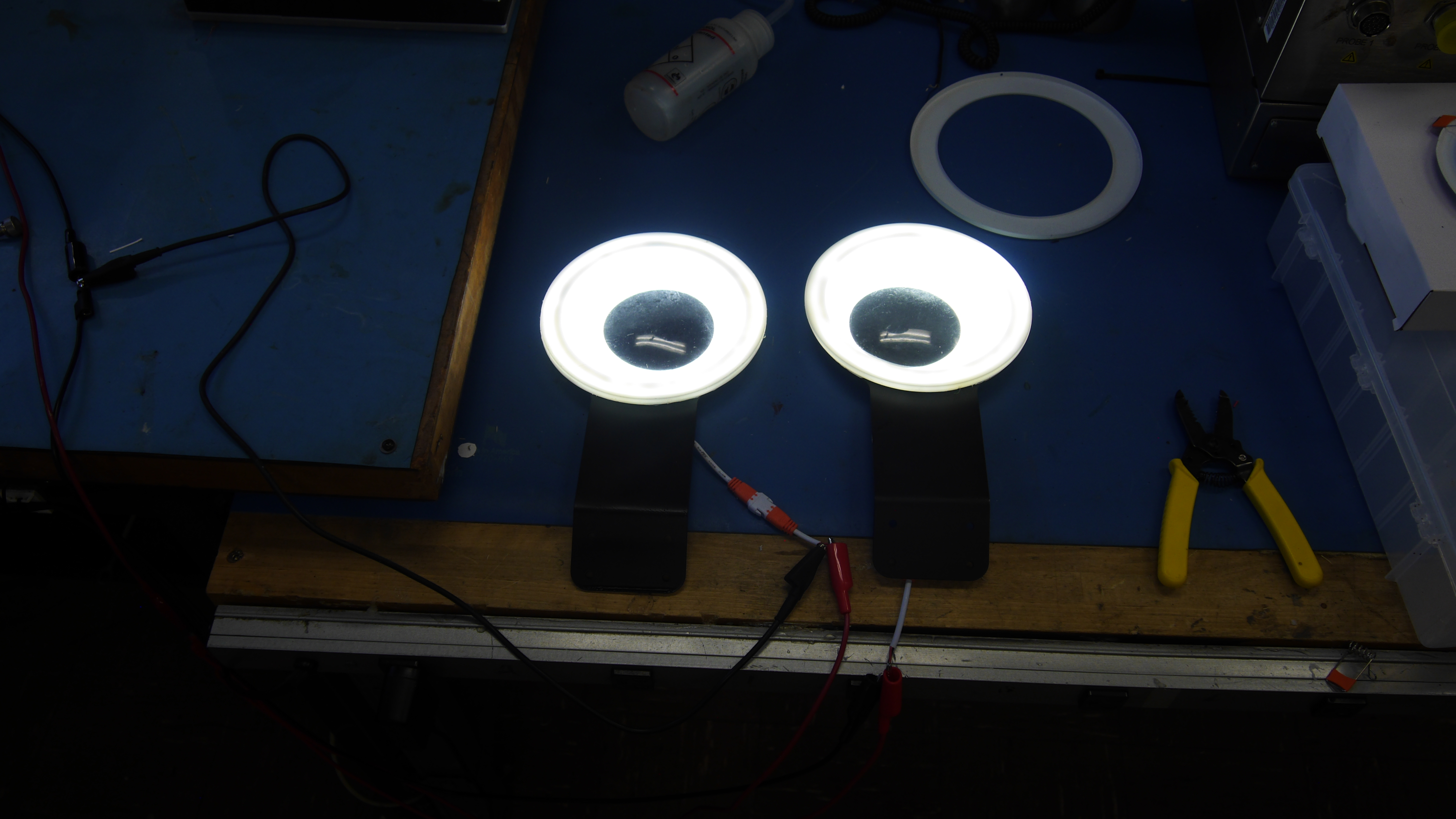 |
 |
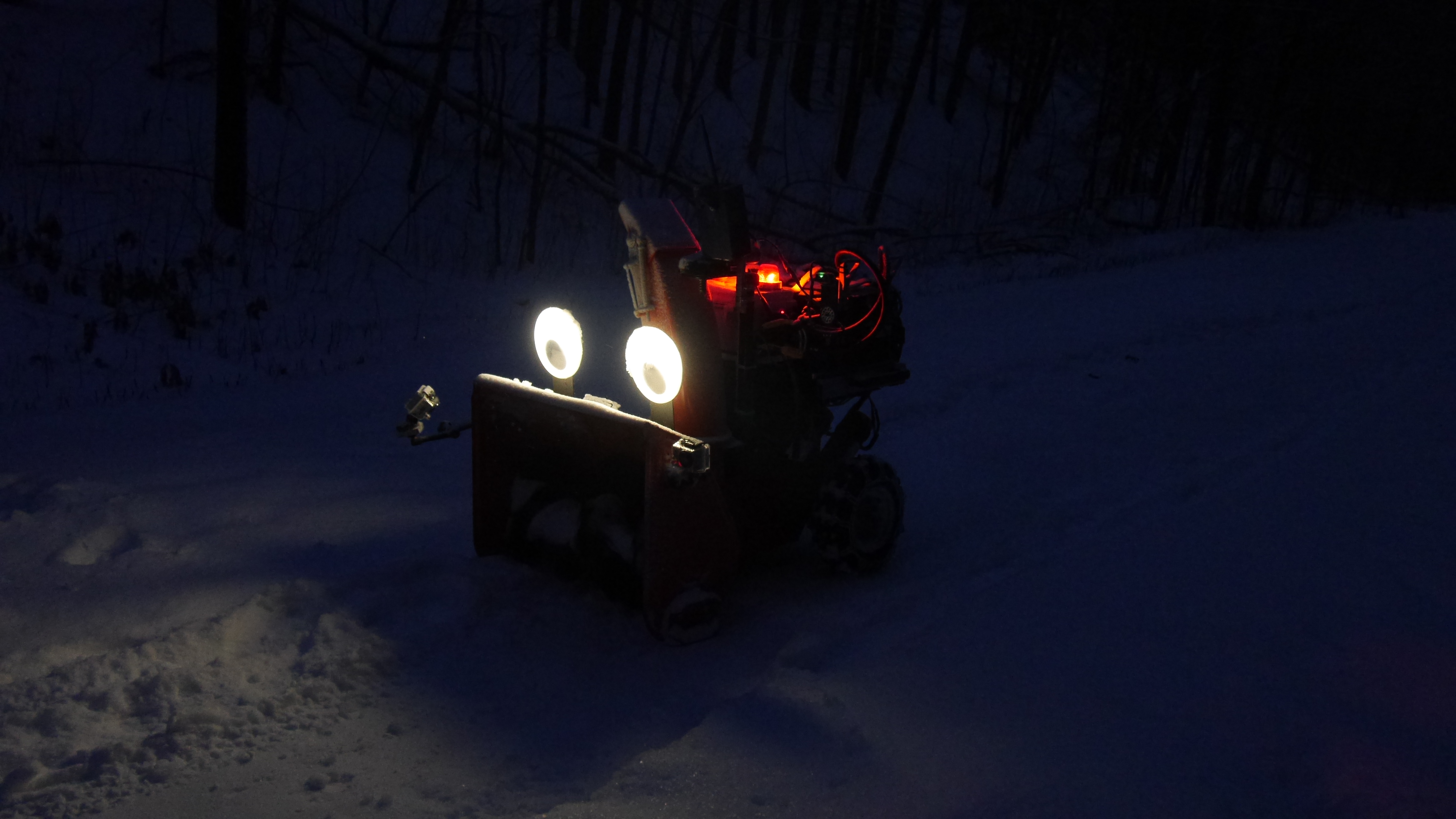


(There's
other photos in the photo
gallery)
Concluding Remarks:- This was incredibly more fun to build than I had expected.
- The bizarre LED high hats were incredibly cheap, which made it less of a loss to modify them.
- Its unclear how long the leds will run at the given power. The supply indicates 300mA / string, which is fairly high at 46ish volts. There apear to be 72 LEDs in the 18w light fixture, at ~3.5v each, or 12 leds in series, 6 in parallel. At 30mA / led that puts the nominal light rating at 180mA, well below the '300ma' shown on the supply.
- I'm going to opt to run these at a bit less then their nameplate rating, hopefully to prevent burnout.
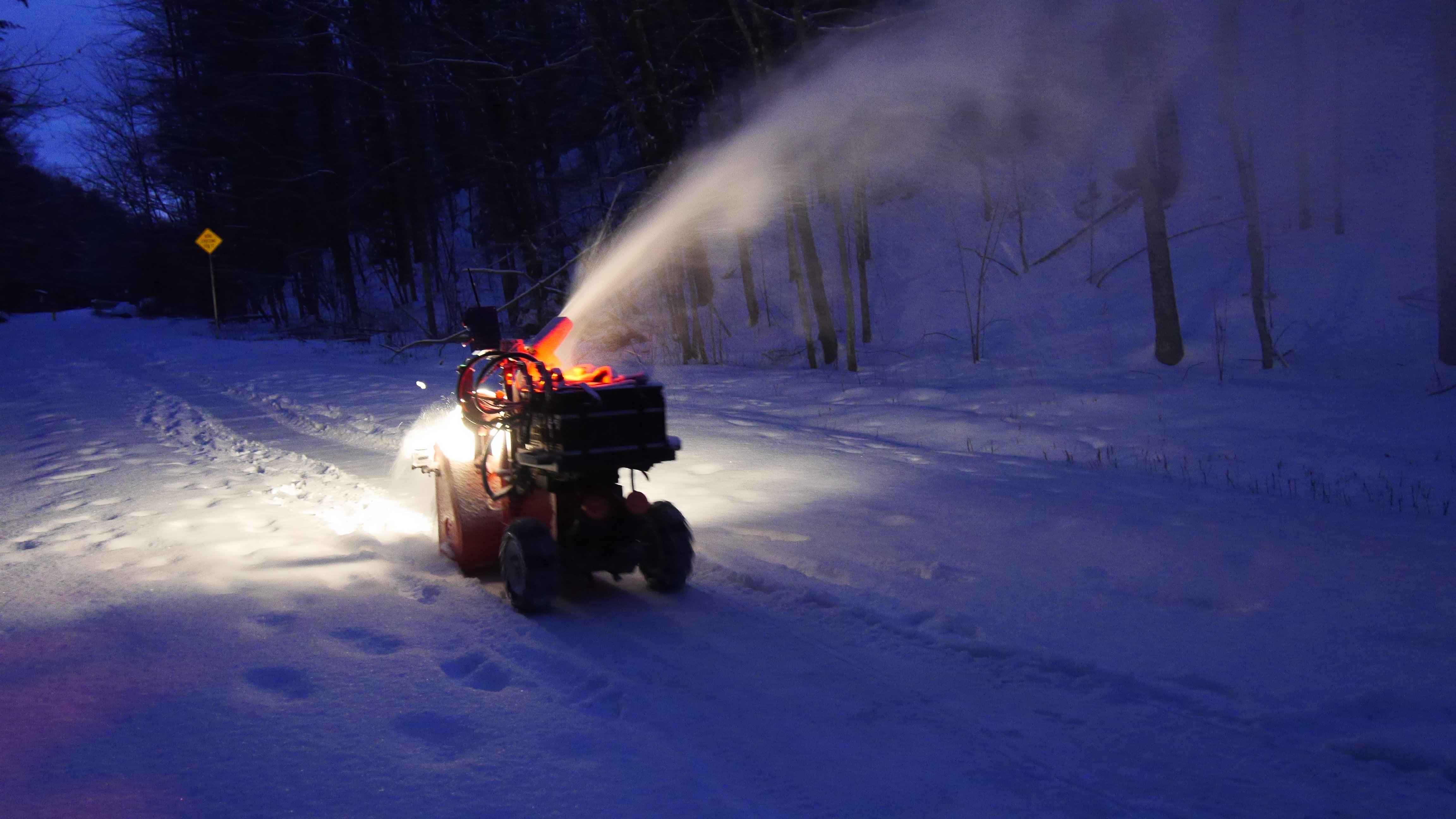
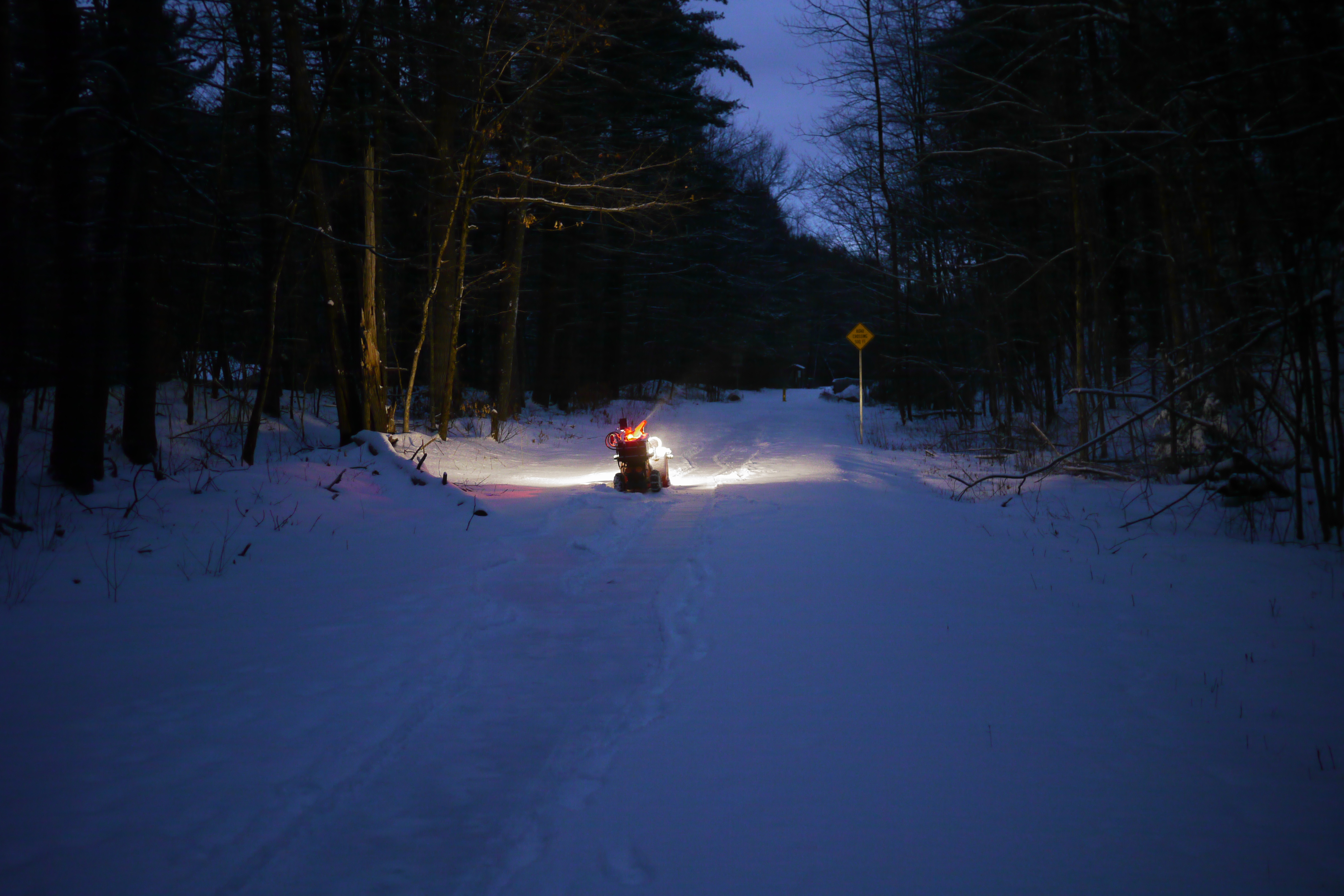
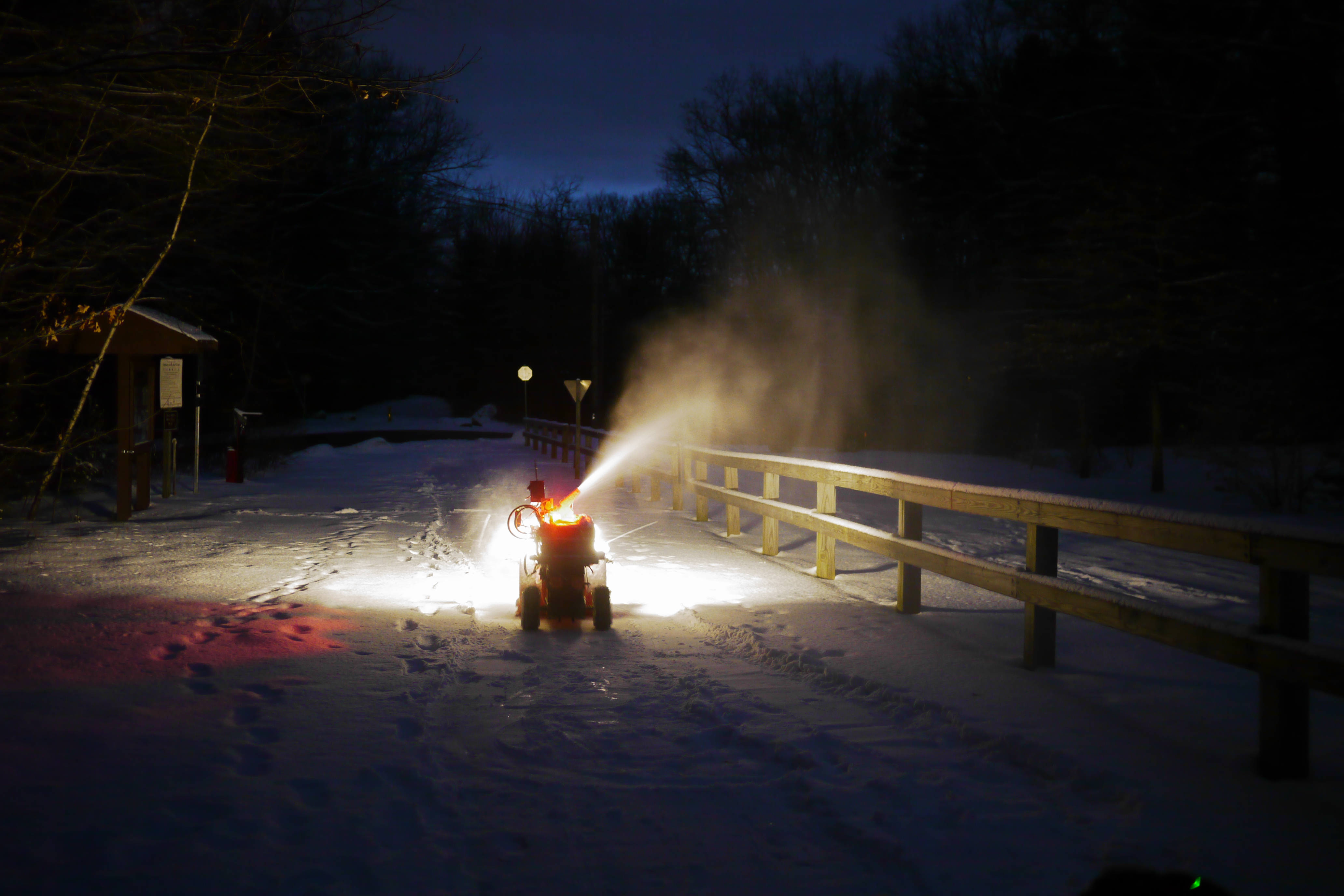
- Snowy evening testing was excellent
| From the sponsors: |
|
|
| Comments: |
|
HTML Comment Box
is loading comments...
|
Dane.Kouttron
Rensselaer Polytechnic Institute
Electrical & Electrical Power
631.978.1650
