Dane.Kouttron

[7.16.19]  Hydro-Foiling On A Small Rowboat

Have you seen the absurd racing sailboats flying about on their hyper-fancy racing hydrofoils?

Want the same experience but on a 10' rowboat?


What?
Outboard Recovery Part 1
Cleaning and Prep Time for Paint Brushless Motor Mounting First Test Testing Notes Conclusion Image Directory


Does your rowboat dream of electric wings?

Have you been watching olympic sailboat racing or other such high speed watercraft lofted high up on their submerged wings?
Isn't it fantastic? Is this implement-able on small scale watercraft? Row-boat scale?

Tune in below to find out more!


<I'm trying a new format, this page is now more-mobile view-able and has a bunch of auto-playing 'animated clips', to complement walls of text, its a work in progress. If your device does not permit auto-play, the animated clips should show a static image>

TIME TO DO SOME HISTORICAL DIGGING
On the last episode we 
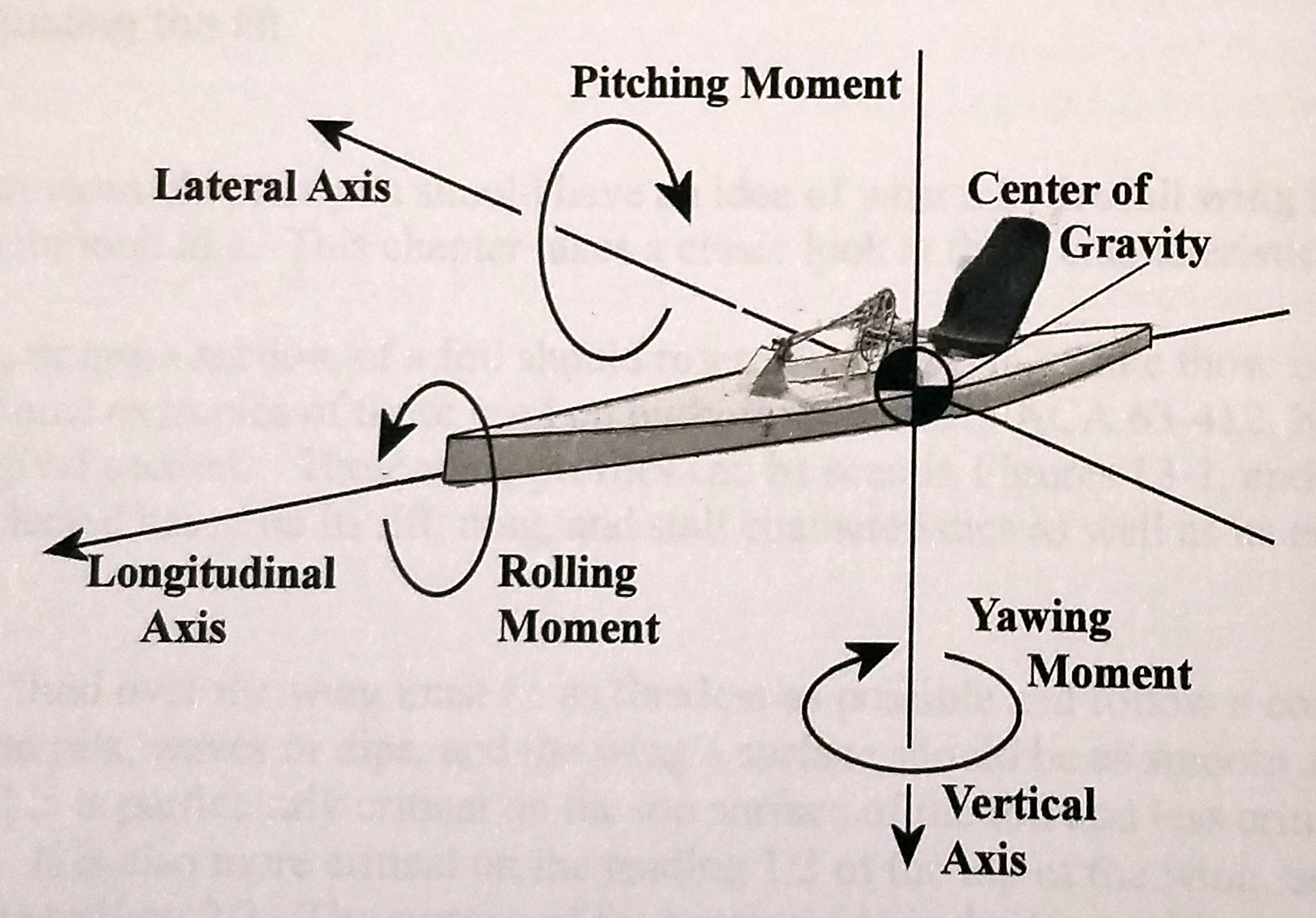
I ended up stumbling on this site [link] which had a number of academic papers on hydrofoil designs. 
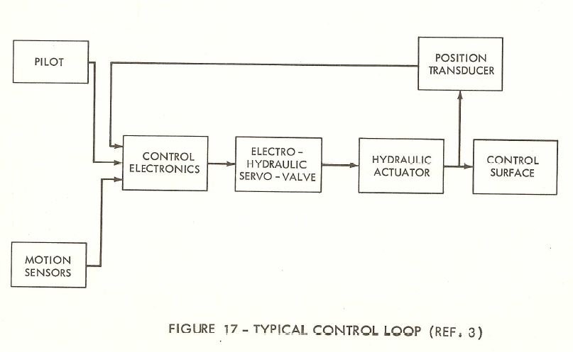
The first work I read through was quite excellent, its Hydrofoil Craft Dynamics In a realistic Sea Including Automatic Control. I checked and its not copyright'd so I OCR'd a version and its available here [link]. 
Lets actually dig deep in this one. I'm going to use snippets here to make sense of things. First off This is a report for the Naval Ship Systems Command, Department of the Navy.
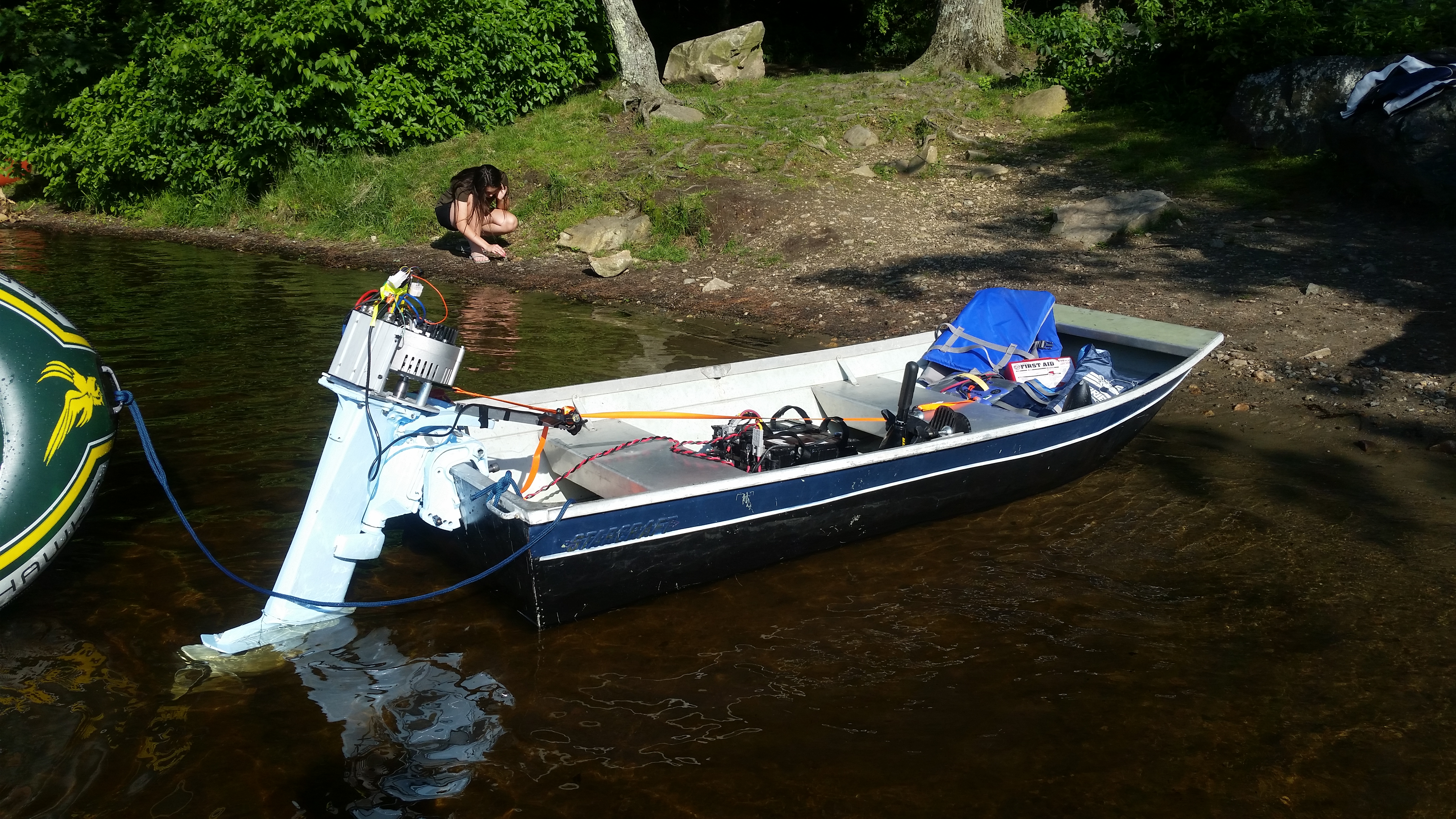
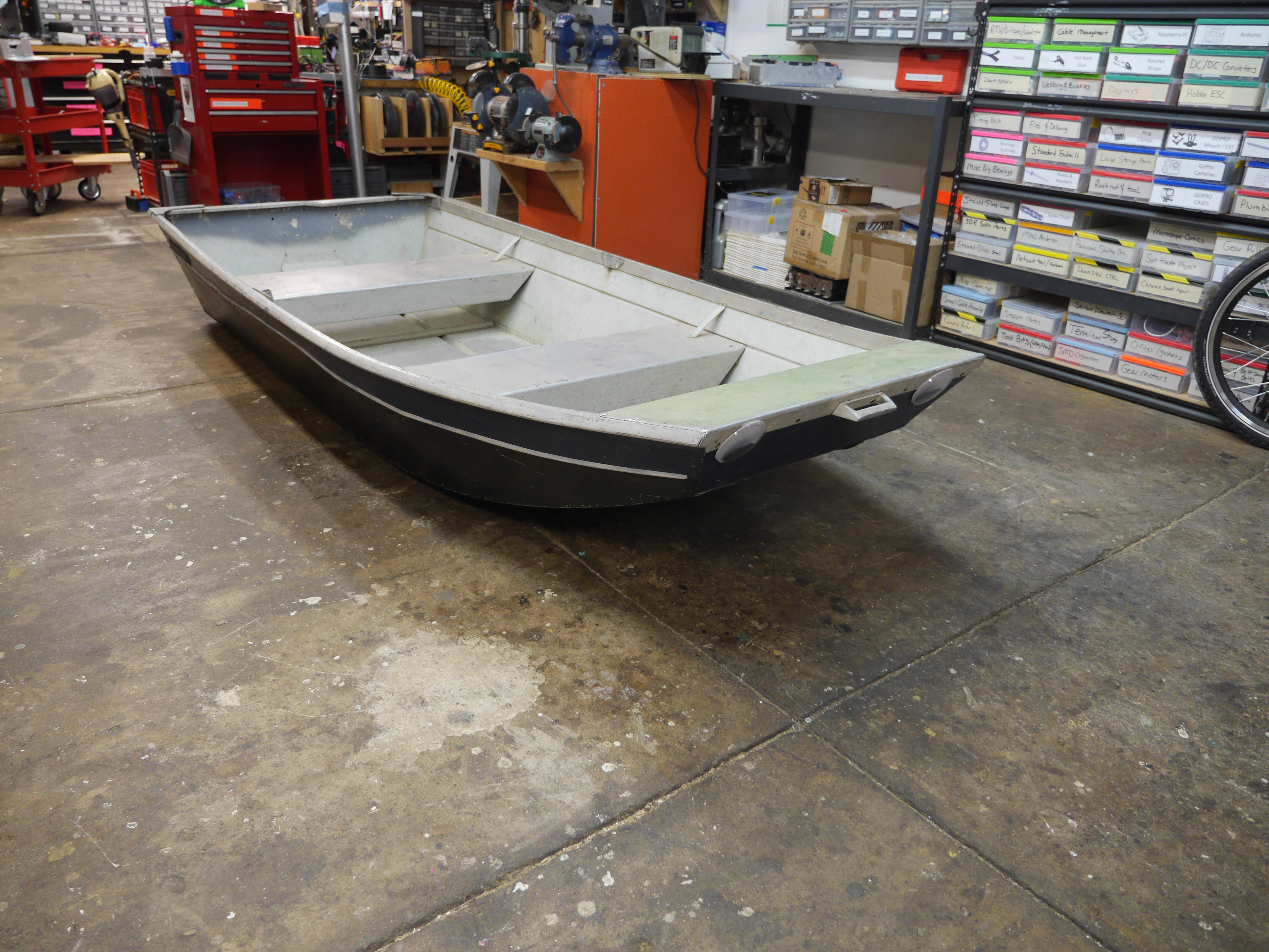


Reading through the Hydrofoil Design Build Fly book

So lets start from the begining, im going to grab some chapter-by-chapter notes, with some details for 
CH2 provides some great verbiage, which will be useful when describing things further in this writeup. First up, a term i had not run into for a while, the Coanda effect: Within limits fluids will conform to a curved surface, to an extent defined for the most part by its viscosity.


CH3: Stability Control and Trim
Stability: tendency to return to steady operation without aid of the pilot. Controllability: Ability of the craft to respond to control surface adjustment  Static Stability: Having a strong tendency to return to equilibrium when displaced.  Dynamic Stability:


Grime and Paint removal


some yt clips
single-person craft, 5hp 18mph: [https://www.youtube.com/watch?v=89ExF3xb-6g]


wood hull thing, 5hp testing looks heavy: https://www.youtube.com/watch?v=SFZwUxEbxW0
making: https://www.youtube.com/watch?v=AyFrls0mg-M


curious contraption, not motorized, pulled:
https://www.youtube.com/watch?v=jWdJUPChj6M


fixed wing, no feedback, wood structure:
https://www.youtube.com/watch?v=t3eX507Xi_I


demo video of a full sized hydrofoil boat (candella)
https://www.youtube.com/watch?v=mMJHXxzLPSc
https://www.youtube.com/watch?v=1mNOGuMCV_I
cad render of candella thing:
https://www.youtube.com/watch?v=abMJ99wtu1Y


really neat design with feedback floats, mounted on a canoe:
https://www.youtube.com/watch?v=fLiltCnjNVM


Book Review time: Hydrofoils Design Build Fly
Its been a while since i bought a book for myself, a lot of time its frankly easy enough to just library-loan a book through MIT, but I actually wanted this book, as it seemed to be exactly what i was after. Herein i'm going to do a abridged book review, pull out some of the interesting tidbits, copy some interesting figures and share some thoughts. Notes from book are in black, Danethoughts(TM) are in red.
Chapter 1: A Brief History Of Hydrofoils
  • [~1861] First testing of wings underwater was
  • [~1895] Mecham Bros built the first working hydrofoil crafts that fundamentally worked. I need to find some of these sketches
  • [~1945] Christopher Hook pioneers use of feelers / mechanisms to adjust foils based on a float in the front of the craft. 
  • [~1960'] Boeing Jet foil boat with submerged foils. 
  • [~1993] Most US Navy hydrofil crafts canceled / decomissioned due to power transmission / maintainince issues. See "BIG JET" Figure.
Personal / Testcraft
  • [~1970] Hi-Foil 2-seat motorcycle hydrofoil, 25hp "longshaft" outboard See "Hi-Foil" Figure I also should look into this as I have a longshaft 25hp outboard and that looks like a jonboat
  • [~1991] Human powered MIT craft wins fastest human hydrofoil holdon wasnt Steve Finberg involved with this?
  • yayayayya
Some digging after reading CH 1
  • Tell me more about this Mecham Brothers crafts

  • Tell me more about this Hi-Foil boat, it literally looks like what I wanted to build. 
    • Hi-Foil has some documentation at the USS Aries Hydrofoil Museum  [link] including a video of an origional Hi-Foil [link
    • Some photos are shown (right), it is more of a jetski than a modified row-boat, but its really interesting.
Chapter 2: Theory of Hydrofoil Flight
  • Fluid density does not have a greatlarge influence on selection of hydrofoils. 
  • Coranda effect: (within limits) fluids will conform to a curved surface when wing around it. This is a function of the viscosity of the fluid
Chapter 3: Stability Control and Trim
  • Stability: The tendency for a flying machine, without the aid of the pilot, to return to setady flight after something causes the macxchine to deviate from steady flight
  • Controlability: The ability of an aircrfaft to respond to control surface displancement to achieve the desired condition in flight. 
  • Axes of rotation: Pitching is a rotation around lateral axis, Rolling is a rotation around the longitiduinal axes, Yawing is rotation around the vertical axis. 
  • Static Stability: Return directly to equilibrium after being preturbed, Dynamic Stability, return to stability after some oscillations.
Chapter 4: Lift, Area and Speed Calculations
  • Chord: The distance between the leading and trailing edge of a wing. Wing thickness should be 10-15% of the thickness of the chord. 
  • The deeper the foil runs below the surface the better
  • Foil angle of attack where the lift/drag ratio is highest (L/D) at cruise or top speed. 
  • Calculating Lift
    • Lift  = 1/2 (fluid density) * Velocity^2 * Surface Area of Foil * Lift Coeficient
    • Quick notes:
      • Lift is proportional to area of the foil (doubling area doubles lift)
      • Doubling speed increases lift by four times 


So lets start from the beginning, behold a 'Jon Boat' aka a 10' roughly buoyant aluminum watercraft. These can be found on Craigslist off-season for 200-400 $ and are remarkably fun, while being lightweight enough to put on a medium-sized vehicle roof. They vary from 9-12 ft long and are born for low speed fishing related activities. Ok so this is what we're working with: 


One of the biggest issues from earlier testing was the transom, or rear of the boat. Its rated for a small trolling motor, and it barely does that well. Shown is just a small 3/4" plywood sheet haphazardly stuck in place to act as a place for trolling motors to attach to. Note the back itself was mildly bent due to using a large outboard without sufficient bracing. The boat physically bent. To get around this the plan was to not only reinforce the back, but to add force distribution hardware to couple the loading into the hull.
Ok time to take some measurements and make cad models.

Here's the first draft model
Note this is a fairly rough model, the actual row-boat / jon-boat has a curved front, there are two seats, etc. The goal was to capture the important dimensions & mount points to allow for a quick modeling and iteration. There are a few overriding goals in this design:
  • Foil hardware should be removable to allow the boat to revert back into its previous configuration
  • All mounting points should be sealed to prevent water ingress when foils are installed or removed
  • Foils should be buoyant, when disconnected they should not sink
  • Transom upgrades should allow for higher power outboard

Continuing on with a top view,


CAD -> Fabricate: Front Wing Pivot Mount & OMAX Waterjet


To do this quickly I opted to waterjet some 1/4" 6061 aluminum plate. Shown is an OMAX, the cut time for the front pivot mount was ~18 minutes, the nice part about designing for waterjet based fabrication is how quickly the parts can be rough assembled, then welded up.

Note there are some cutouts shown, the rectangular cutouts are to allow for some cookie-cutter-style design, where the mating parts not only can be welded from the working side of the part but also from the through-hole tabbed side.

Waterjet -> Weldment: Fixturing and Tig welding


For surface prep I used ethanol and a wire brush, at the beginning I opted for outer-facing welds and then subsequently worked my way in. As a note 1/4" aluminum plate is a fairly huge heat-sink, so a good amount of time was used to pre-heat the part. My tactic for pre-heating is to wave the tig arc over the surface I plan on welding for a fairly significant amount of time, which is shown a bit in the sped-up clip shown right. The welder used was a 200A Dynasty, with an ambient water-cooled head. Nominal welding current was 150A max.

Given that the large hole going between the left and right weldment need some fairly precise alignment, i should have opted to make a pin to keep the two holes concentric, fortunately the clamping and fixturing kept both remarkably aligned.
Weld Cleanup


As the front foil pivot is fairly visible and prominent, I sanded down the weld surfaces to improve the finish. Note only the outer surfaces were welded, the inner cavities were tacked in place but the advantage of fully welding the part was fairly limited. Another point of reference, making long continuous weld-beads on aluminum also provides a fairly straight path for cracks to form, as such the welds were periodically interrupted.
The abrasive disks I'm using here are nominally called 'flappy disks or flap disks', they are basically small sheets of sandpaper attached radially to a base. I used a 120 grit flap disk for the coarse removal and then a 300 grit disk for final cleanup.
Yes I'm still using an 18v dewalt and its impressive how quick it chews thru the 2ah 18v a123 era dewalt packs.


Many Many Weldments and sub-assemblies


The front foil pivot mount is not the only weldment, there are many more aluminum widgets. The foil braces, foil mounts and other pivot hardware all came together after a power-hour of welding and subsequent cleanup.

Preparing the Rear-Foil external mount plates


To keep with the theme of allowing the foils to be removed quickly and not heavily interfere with the watercraft, the mounts for the rear foils purposely have very little sticking out into the flowing water. To do this i opted for 3/8-16 recessed Flathead Allen key screws. This is a fair amount of recessing and to do so I used one of my favorite countersinks, a vibration-resistant through hole countersink. This same bit was used to countersink hardware on the Valkyrie battle-bot base frame.
Attaching the outside of the foil mounts


The goal of the rear foil mounts is easy-to-remove, and as such the outer plate is literally a breadboard for plugging in different foil designs. That first outer plate becomes a 'permanent' part of the vessel. Around the perimeter of the attachment points are eight separate 1/4-20 threaded holes for attaching various mounts. To help reduce water ingress, silicone is used around the holes thru the shell.
Bolting together the rear-foil mount points


The flathead 3/8-16 bolts pass thru the hull and mate to an inner weldment that transfers both foil forces into the hull and out to the outboard. Silicone was used again to provide some sealant on the mating holes. 3/8-16 nylock locking nuts were used to sandwich the whole assembly together. After everything sat for an hour the outer perimeter was cleaned up and a small bead of silicone was routed around the inner facing sub-assembly.
zzzzz


Updating the Labeling: Wub Craft


I noticed that the boat had labeling at one point in its previous life. Apparently starcraft is not only a video game but also a rowboat. The angle grinder is already within arms reach, so its time to update the crafts labeling on both sides. I was surprised that the plastic labels were riveted in place, but it probably works way better than an epoxy. To make the new labeling I found a similar font, sorted the scaling and went for a similar design.

'Wub' is my proverbial interchangeable unit of force/frequency/magnetic field strength/current/wattage.
Interestingly this is a fairly low key label, so much so that only one or two folks noticed it while helping unload the craft. It fits in remarkably well.
Wait, I want to see how that logo was made


Here's the waterjet with the splash-guard removed so the cut path is more visible. This is 1/8" 6061 aluminum sheet. Note the footage starts after all the pierce cuts as the pierces cause a lot of ejecta / splashing. Aren't water-jets amazing? The brown material is the garnite that is injected into the water-stream to aide in cutting. The abrasive is consumed during the process of cutting. Note that both orientations of this logo were cut, so both sides of the craft matched :  ]


Adding some character: Ginormous googly-eyes

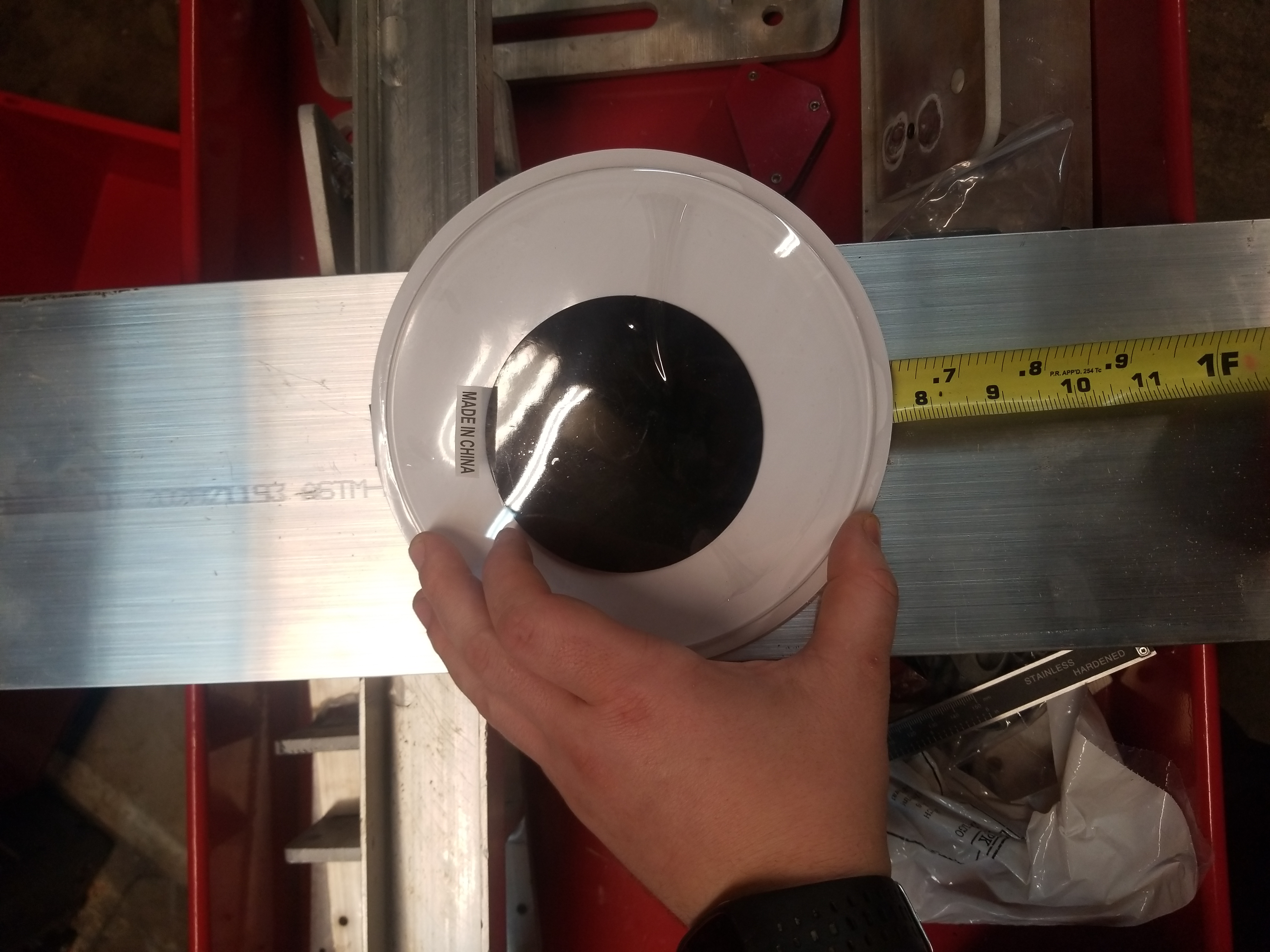
I purchased some comically large googly eyes in a two-pack. To get them to survive on the rowboat, they're going to need some type of holder, generally these are actually backed by laminated cardboard so water ingress can cause problems. I'm going to opt for the same route I took on the snow-blower robot googly eyes: lasercut plastic thermally formed to match whatever mounting angle makes sense.
Googly Eye Holder


When designing for lasercut parts its sometimes important to avoid un-necessairlly large open cutouts. The googly eye assembly is actually three parts, the base, and two eye-holder ring-lets. By splitting the two the parts waste less source material.


Time to laser

With the cad hastily completed, i grabbed some 1/8" / 3mm acetyl stock and ran the cut on a 120w Epilog co2 laser cutter. Both Eyes were cut from scrap stock and came out excellent. I sized the outer ring to grab onto the lip of the googly eye, partially to keep it mechanically constrained and in part to make assembly easier.


Googly Assembly Time
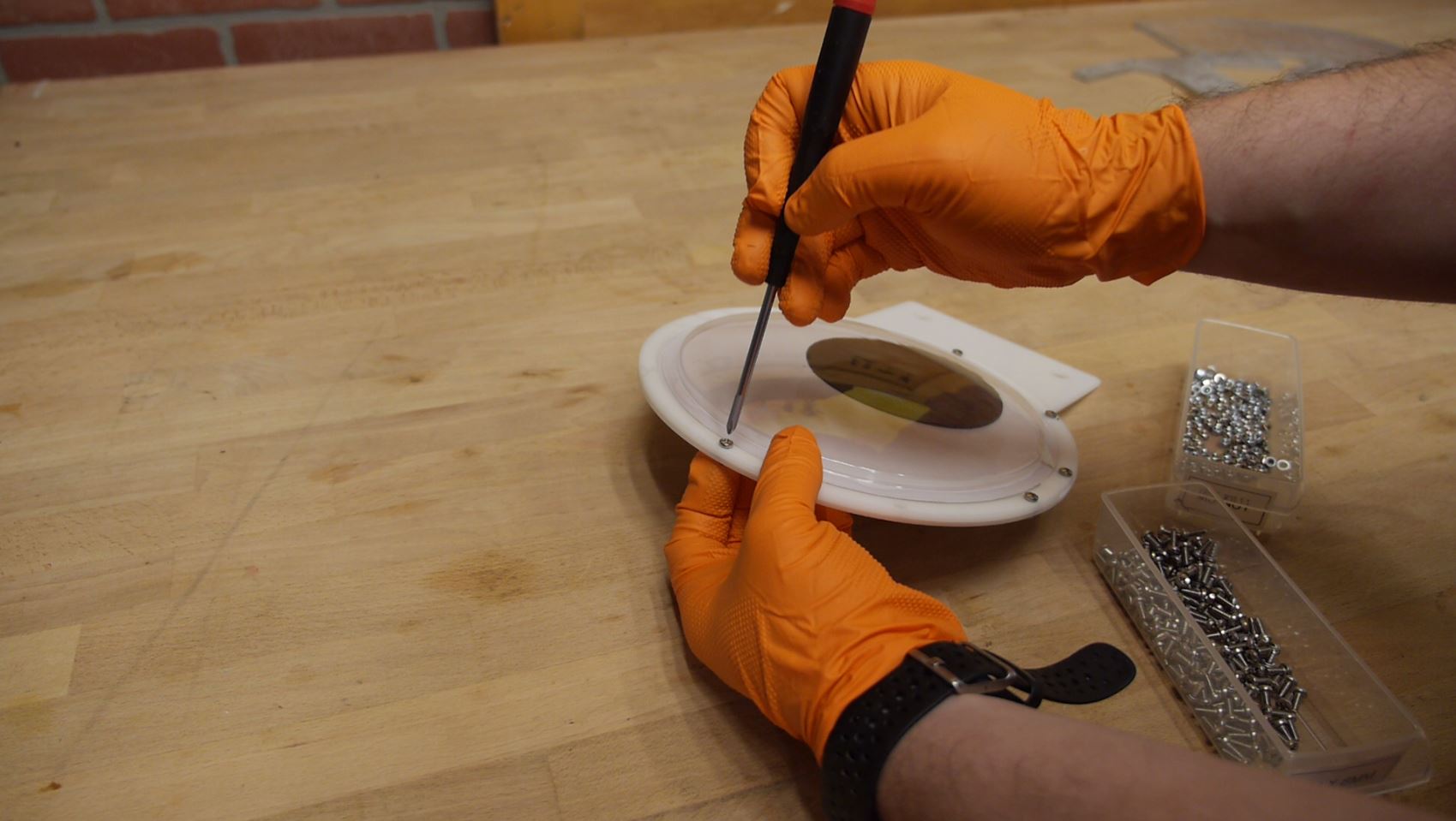
To assemble these i just used small M4 Phillips 10mm screws and nylocks. If I had thicker backing material I may have been able to get away with self-tapping plastite screws, but overall this was fairly quick. RTV was added around the perimeter of the googly eye to prevent water ingress, as the backing material was likely made of thin cardboard
Thermal Bending Acetal / Delrin

To get the right angle on the bottom, I opted for a simple thermal bend. This is fairly straightforward, but there are a few key takeaways


  • Use a table edge or preferably a metal surface edge
  • Try and find a concentrated hot air source, blow dryers are fairly wide whereas heat guns tend to be more concentrated
  • Most plastics are poor thermal conductors, as such it is important to heat both sides.
  • During folding the material may want to spring back, sometimes its easier to over-bend slightly to compensate for this


This is a short clip of the thermal bend process that I've found works well. Note i was using gloves due to silicone / RTV which was present on the googley eyes.


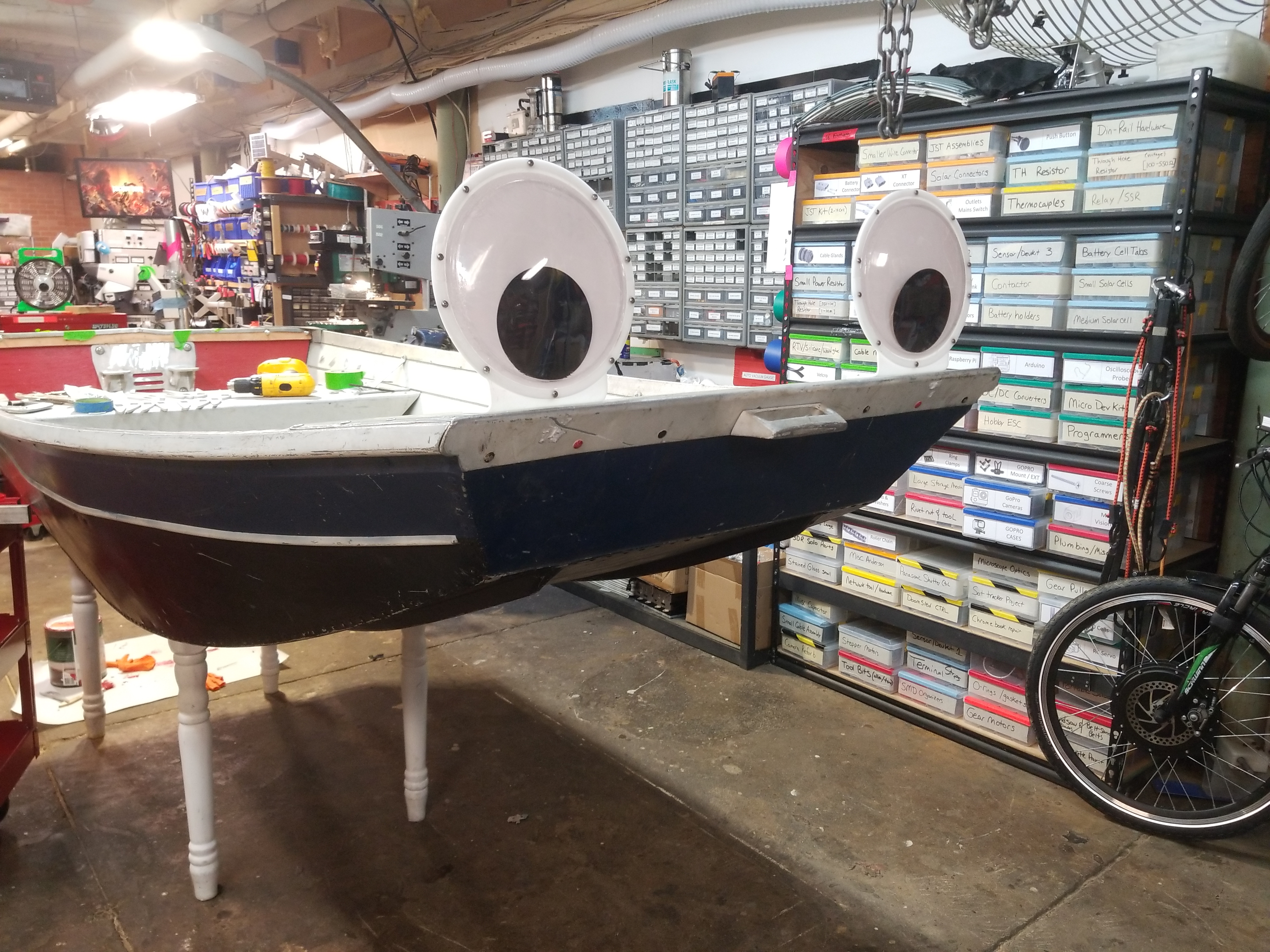
With the folds complete I did a quick mock-up of where i wanted them to sit. Spaced just about to the ends had the maximum goof factor. It should be pretty obvious that these are not intended to be installed all the time, so to make them easily removable I opted for small thumbscrews. To make a solid mounting point I used rivet-nuts, which are my new favorite thing. Want to put a threaded boss in some thin plate? RIVET NUT IS HERE FOR YOU
Adding In Rivet Nuts


This was a really good use for a rivet nut, the thin aluminum sheet on the top front of the boat is too put threads into, the underside is awkward to get to for holding a nut and tension-ing from the top. Shown is attaching the rivet nuts, its not the best view, but the tool shown basically applies force to deform the nut to get it to hold in place on the thin sheet metal.

With these installed, each googly-eye gets a thumbscrew for quick attach/ removal from the boat.
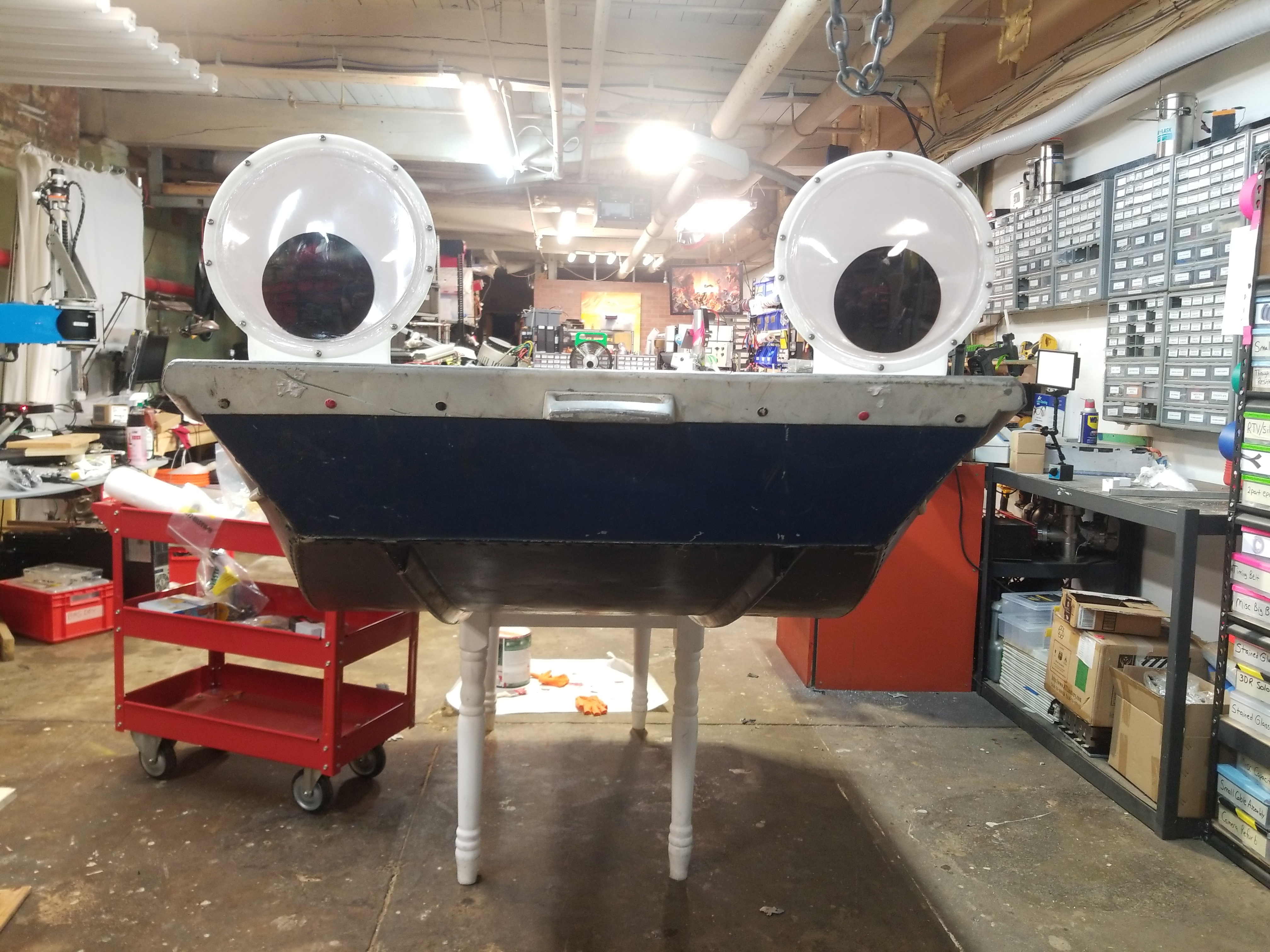

Googly Eye Reveal 


Look at how wonderful this silly creature looks.


Bill Of materials
Price & Quantity
Media
Giant Googly Eyes (7" diameter)

These were fairly well made, but had a laminated cardboard backing. To prevent the backing from getting wet i opted for a fairly substantial amount of RTV / silicone to limit water ingress.  [link]
$12.29 USD / 2

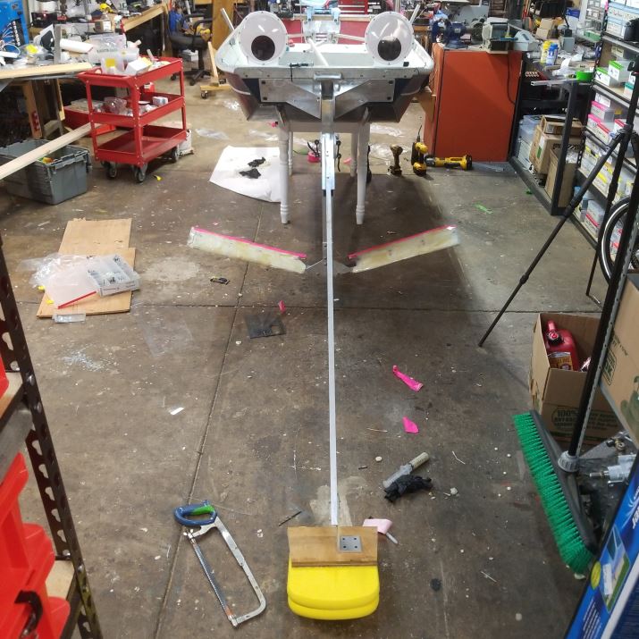
Surface Follower (Floaties)

I needed something buoyant to follow the water's surface in front of the craft, and admittedly a bit last-minute. These worked well in a pinch, and were literally held on by some long wood screws.
[link]
$11.99 USD Each


Notes from the first test
* A better transom mount is required.
During the first test, I relied on the existing, small wooden transom mount. It worked splendidly for a small 12v trolling motor, but became an issue whenever the outboard was pushed to more than ~30% power, as the rear of the boat started to become less structural. A new mount that ties together the back of the rowboat would really make a difference. For the test, the torsional forces were mitigated temporairally by adding a ratchet strap to the center seal area, but  the amount of force applied but it was still rather tenuous, all things considered. Mechanically reinforcing the back and making attachment points for carrying the forward force into the hull is a must, moving forward. 
* Tilt adjust on the transom is a good idea
The actual 'trim' that the outboard had in-water is actually fairly important as it nominally defines how the watercraft wil perform. After the first test I consulted a few colleagues with more time at sea than myself, as it turns out 'trimming' is its own art to an extent. 
* The height of the prop is also fairly important.
This particular outboard is a 'long shaft' style outboard, which is intended for mounting higher up on a watercraft. As my rowboat is incredibly low to the water, this doesn't work out that wonderfully as the two combined result in a lot of hydro-drag. 
*Hear me out, hydrofoil
The results of this first test were curious, mechanically the prop turned, the motor was happy and the electronics stayed under control. The big issue was the outboard being incredibly long, it caused quite a lot of hydro drag being so far underwater. Lets start with a conventional setup, a watercraft that would take a 35hp outboard is generally a bit higher off the water and generally 12-18' long. Lets start with the assumption that this watercrafts transom is 6-8" higher off the water surface than my row boat. Now, lets shift to a 'long body' outboard, which, research suggests is 10" longer than the same outboard model that is not the long-body style. We're now seeing a roughly 16-18" difference in prop height. This is a significant difference in prop height and resulted in a bit of drag. Not all is lost though, 16" is enough to lay in a small hydrofoil under the craft. I'm talking a set of wings to hold the craft out of the water and up in the air. This would significantly reduce the hydro load on the craft while also making proper use of the long body'ed outboard. Its not unheard of to add a hydrofoil to smaller craft, competitive sailing folk do it frequently.  A curiosity for another weekend indeed.
* Maybe Pontoons is a good intermediate solution to twiddling with a hydrofoil?
If the outboard is more suited for a raied craft, maybe raising the existing row boat out of the water and reducing its footprint is feasible. I imagine some ripstop nylon or vinyl sheet may work quite well for this application, as the fabrication would nominally require a long tube and possibly some ratchet strap points to keep everything connected.
* The DC link cabling wasn't appropriate
As this was a test, and I didn't know where the prismatic battery modules would end up living, so I opted for using a longer dc-link cable. This cable was 8 gauge which, at the current that was being consumed, was rather small. As a result under heavy load the controller would buckle as its DC feed was probably dropping fairly hard. Realistically the  battery module ideally lives a short wire run away from the motor controller and uses ~2-4 gauge wiring, and a substantial connector. 
*The controller and cabling need a shroud, the motor needs a coolant fan
While there weren't any significant overheating events, the motor was running quite warm under load. A quick option for providing cooling at the top of the motor is either a better designed impeller, or a proper blower. This could be a simple 3d printed fan attached to the motor shaft, or something off-the-shelf that fits.  The existing impeller for the motor is rather mediocre. Finally as this is not a sensor less controller, grabbing a few watts off a motor phase isn't a terribly bad decision, and gets around having to run separate isolated cabling just to run a fan.  The VRMS on the motor phase should be, worst case, vbatt, peak to peak, and running that through a rectifier and into a proper blower should dramatically increase the cooling capabilities. Another option is to add a water jacket to the motor but that seems fairly overkill. It may allow running higher than rated motor current, but its unclear how much extra power is reasonable. The controller itself may also benefit from forced air cooling.
*Motor Temperature and controller temperature
The motor has an internal thermistor, but i do not utilize it yet. Having a thermal output reading gives a reasonable indication of motor overloading. The controller at present actually allows for a 'boost' mode, There's a peculiar chart of the boost and economy modes, shown (right). This is a little confusing, there are two modes, "Economy" and "boost", the way this is intended to work is if boost mode  is enabled in the controller, selecting it by toggling the BRK_AN(2) line high results in the maximum current being IMAX, when BRK_AN(2) is toggled low, the max current is 60% of IMAX. So, for this to work, the actual max current is set higher than expected, and you operate normally at 60% of that value. Its an interesting setup and could result in a neat 'I need 40% more please' mode. 
*Reverse
I havent wired in reverse yet, I'm a bit anxious about including reverse as at full power its an excellent way to capsize the craft. The controller supports  'half speed in reverse' which is actually impressively useful in this application. I'm still anxious about enabling it, maybe some extra on board flotation is required in the back of the craft.
*Telemetry
It would be great to grab telemetry of DC bus current, Phase current and motor RPM, along with motor temperature. Technically most of this information is sent out the 4 wire TTL uart port of the controller but its not presently documented in the manual. Kelly controls actually sells a blue tooth module that can connect to this along with an APK for android, but I have not yet tried it out / verified it supports data logging. One reason having motor rpm available would be to indicate what band the motor is operating in, is it hovering in the 2k rpm region at full current, or is it approaching 5k rpm? If I'm only hitting half of the target rpm at full current this would be a great indicator that the motor could benefit from a belt reduction, resulting in the motor operating at a higher rpm and transferring more power to the prop.
* Error Indication
Right now the Kelly Controller outputs blink codes to indicate different error modes. At present those led indicators are located in a bit of a precarious location. Either being able to read these over the coms link, or, remot-ing the indicators would be useful for in-field debugging.
* Waterproof throttle
One of the parts that i was a bit precarious about was the simple hall-throttle i had been using for throttle. They are notoriously bad when it comes to moisture. Oddly enough 'waterproof scooter throttle' isnt really an off the shelf item yet. I imagine the throttle out of a zero-electric motorcycle probably actually works in the rain but at the moment the concept of 'the throttle got wet and the boat decided to apply max power' is a bit of an issue. There are a few solutions, conformal coating spray applied tothe hall effect sensor, finding an actual waterproof throttle, or, simply using a set of well tested waterproof pushbuttons to simulate different throttle settings. possibly a sealed multi position switch and a forward pushbutton? It would be neat to actually have a bell call lever for throttle set and some type of dead mans switch to prevent 'runaway boat' syndrome.
* A shroud for the mechanicals
Finally, adding a shroud around the top to clean up the look of the outboard would be great for also hiding the cabling and any exposed rotating parts. It would be pretty excellent to go for some ~60's era spaceman-spiff look,
* An Emergency Stop
The correct wiring for this motor controller uses a contactor to enable / disable the drive, which, for all purposes is a good idea. During this test i wired the battery bus directly to the input for simplicity but having a contactor and a pre-charge is a really good idea going forward.
* Detecting leakage current
One interesting mechanism to limit and detect to the hazards of medium voltages in a watercraft is to having indication for hull to battery leakage. I imagine if there's any voltage present between hull and Batt +, its a good idea to stop and determine why or what is leaking. This may be a DC leakage path, or high frequency AC coupled through to the hull.  I hesitate to use a ground fault indicator as, well, this is a DC low voltage application but it may be a good idea to investigate what is available in that realm. I imagine there's 48V DC widgets on swanky yachts, or sail craft, so there may be associated safety hardware. Finally using a large system fuse, with an indicator would be a great last step forward, having a zener-resistor led setup to display 'your fuse is blown' would be quite great. DC circuit breakers at that power level are a bit expensive or huge, most reasonable sized ones end around 50V, at 50A DC.


Solid part files


(There's other photos in the photo gallery)
Concluding Remarks:


If you have questions or comments, ask below or send over an email.
Comments:
HTML Comment Box is loading comments...

Stay safe when working with electrons in aqueous environments. Also wear sunscreen, I'm not responsible for your newly acquired farmers tan : ]

Dane.Kouttron
Rensselaer Polytechnic Institute 
Electrical & Electrical Power
631.978.1650