Dane.Kouttron
[7.16.19] High Power Electric Outboard: V2
  This
project centers around reviving a 1983 Evinrude 35hp
long-shaft outboard and converting to electric. The
outboard was heavily corroded but was the right price
(free). Follow along for the disassembly, repair and
electrification. Future plottings, CAD files and diagrams
included below. This
project centers around reviving a 1983 Evinrude 35hp
long-shaft outboard and converting to electric. The
outboard was heavily corroded but was the right price
(free). Follow along for the disassembly, repair and
electrification. Future plottings, CAD files and diagrams
included below. |
| What? |
Outboard
Recovery Part 1 |
Cleaning and Prep | Time for Paint | Brushless Motor Mounting | First Test | Testing Notes | Conclusion | Image Directory |
| Attempts at
recovering the outboard |
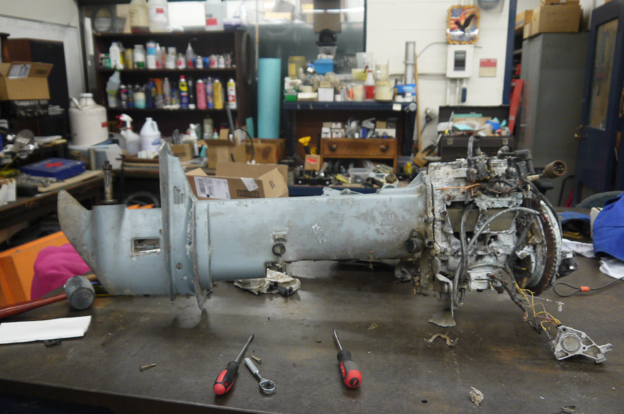
  Here's the outboard host,
fresh from its trip back from New Hampshire. An
excellent comrade helped out by grabbing it from the,
more local, seller. Its fiberglass cover did a good
job at hiding the engine's state of sadness. It was
quite far gone, there was no chance that even the
finest in combustion-izers could resuscitate this
beast. It did have a few things going for it,
everything below the engine looked in good condition.
This only makes sense if the engine was stored, upside
down, with its fiberglass engine cover filled with
water. Bizarre. Here's the outboard host,
fresh from its trip back from New Hampshire. An
excellent comrade helped out by grabbing it from the,
more local, seller. Its fiberglass cover did a good
job at hiding the engine's state of sadness. It was
quite far gone, there was no chance that even the
finest in combustion-izers could resuscitate this
beast. It did have a few things going for it,
everything below the engine looked in good condition.
This only makes sense if the engine was stored, upside
down, with its fiberglass engine cover filled with
water. Bizarre.This is what the engine is supposed to look like [link] |
  The outboard came from
the magical craigslist, and was picked up by ever excellent, Ted of
New Hampshire. We spent a solid 3 hours in miters
trying to de-engine the beast. Bolts were sawed off,
drilled out and everything that should have removed it
was removed. A couple dozen sledge-hammer blows were
applied to 'loosen' the engine from its outboard
clutches, to no avail the engine blob was stuck. The outboard came from
the magical craigslist, and was picked up by ever excellent, Ted of
New Hampshire. We spent a solid 3 hours in miters
trying to de-engine the beast. Bolts were sawed off,
drilled out and everything that should have removed it
was removed. A couple dozen sledge-hammer blows were
applied to 'loosen' the engine from its outboard
clutches, to no avail the engine blob was stuck.
|
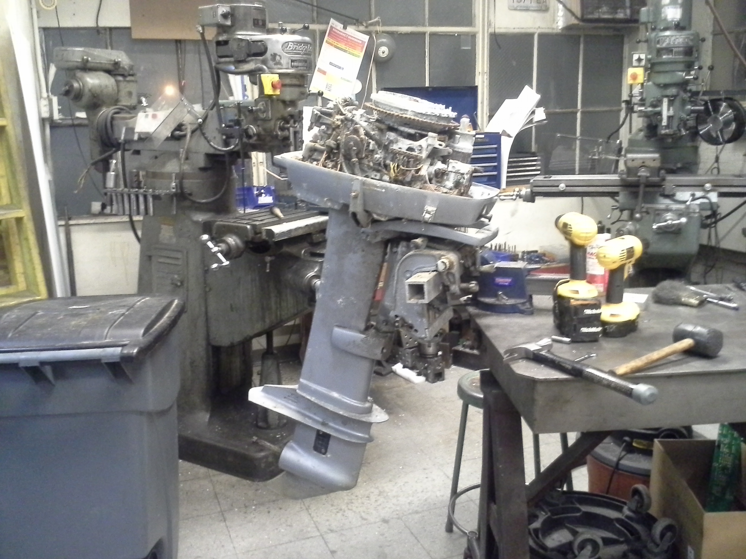
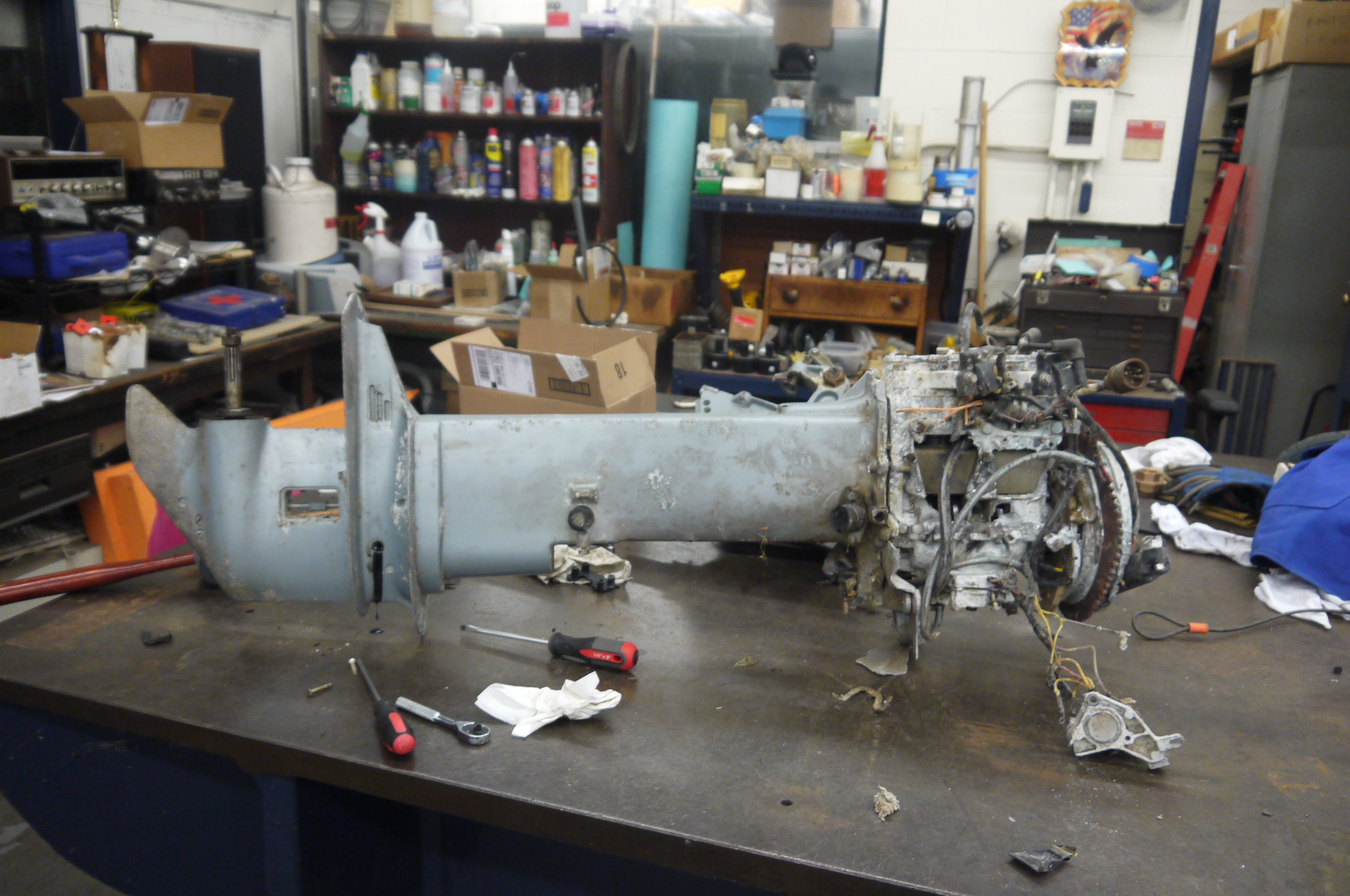
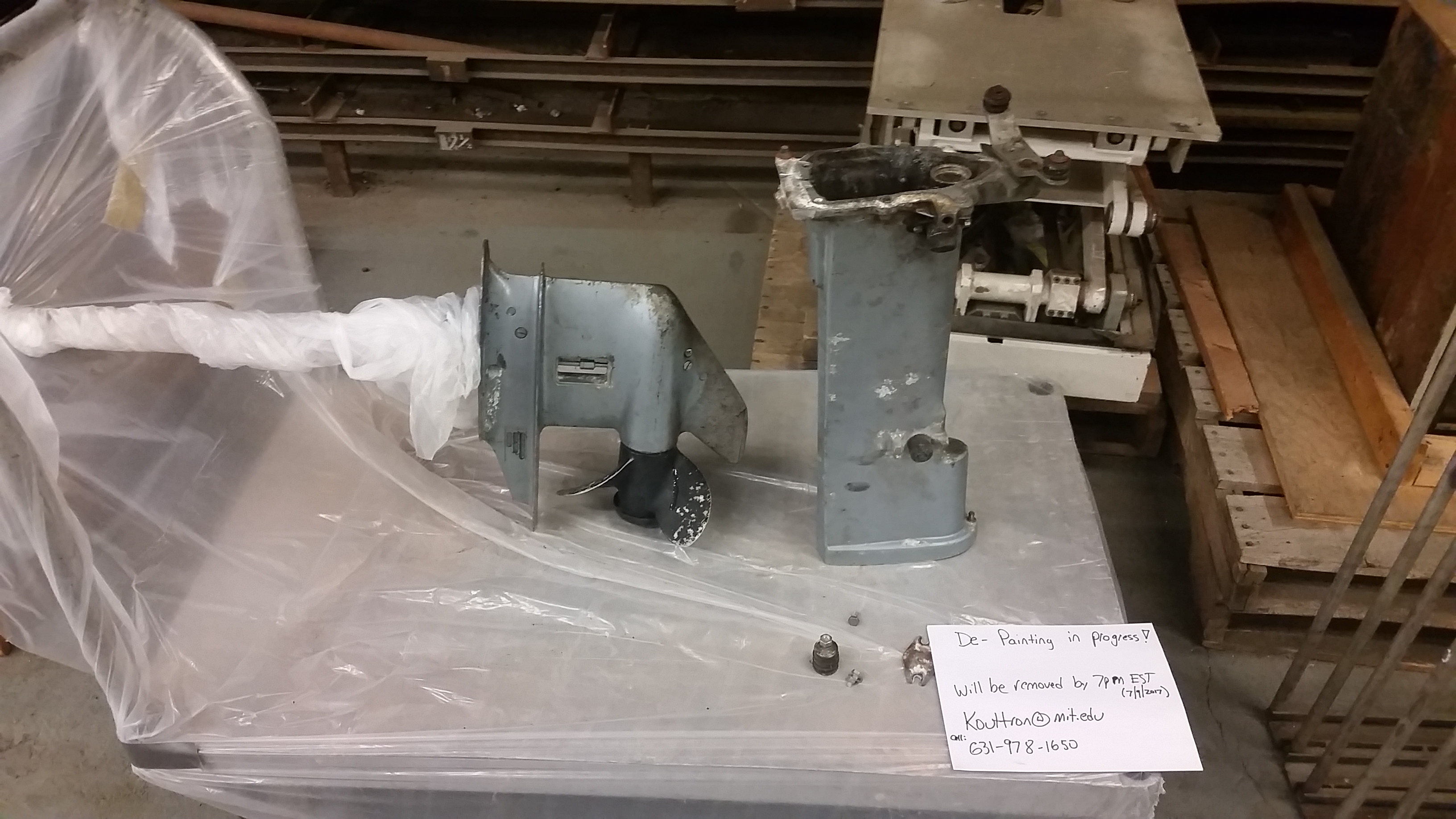
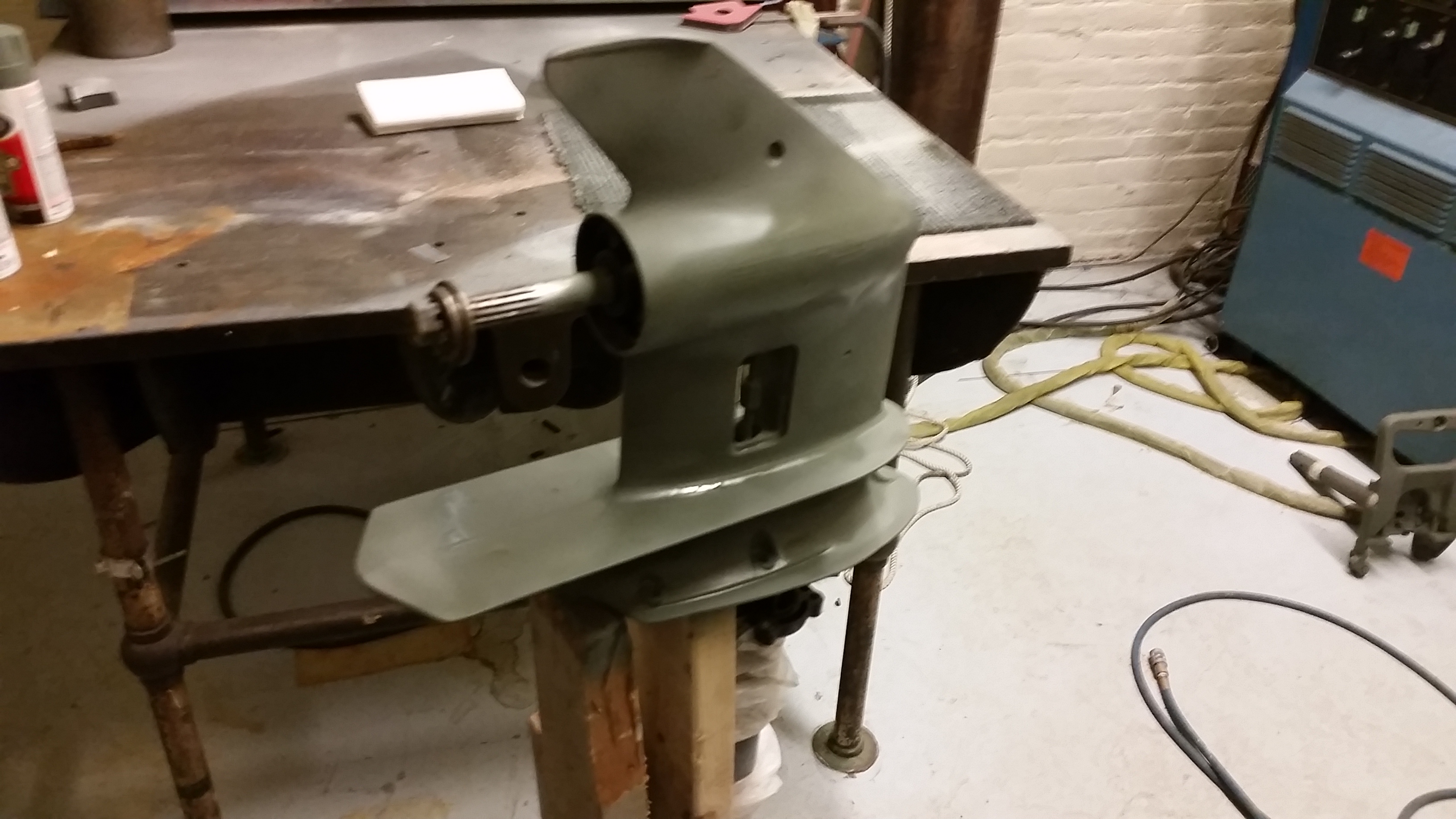
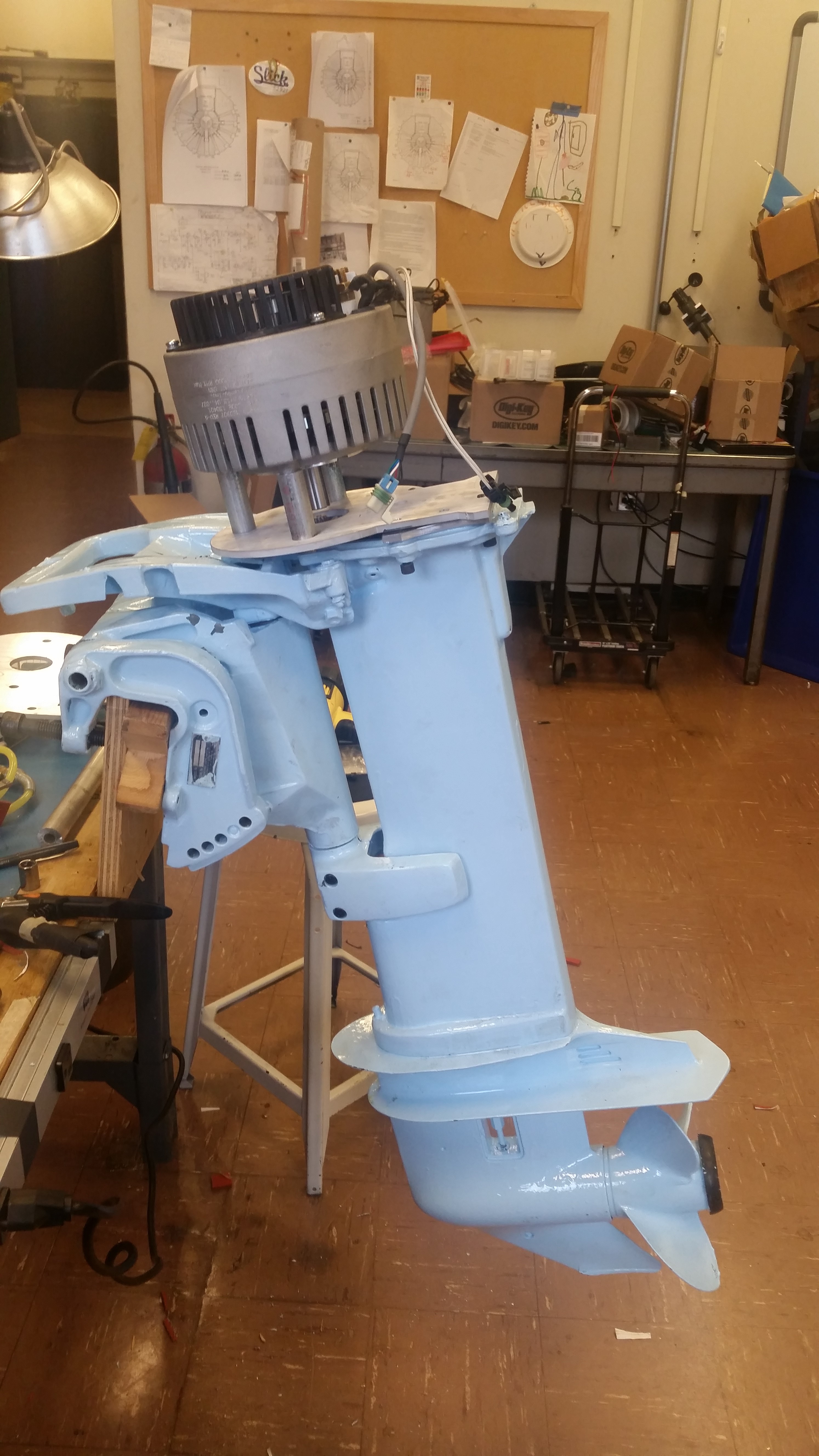
  Fast forward ~6 months,
the outboard with the very sad engine had been sitting
in a stairwell. Now that it was summer I began
plotting power boating. Time to re-evaluate 'free
giant outboard'. It was dragged onto the bench and
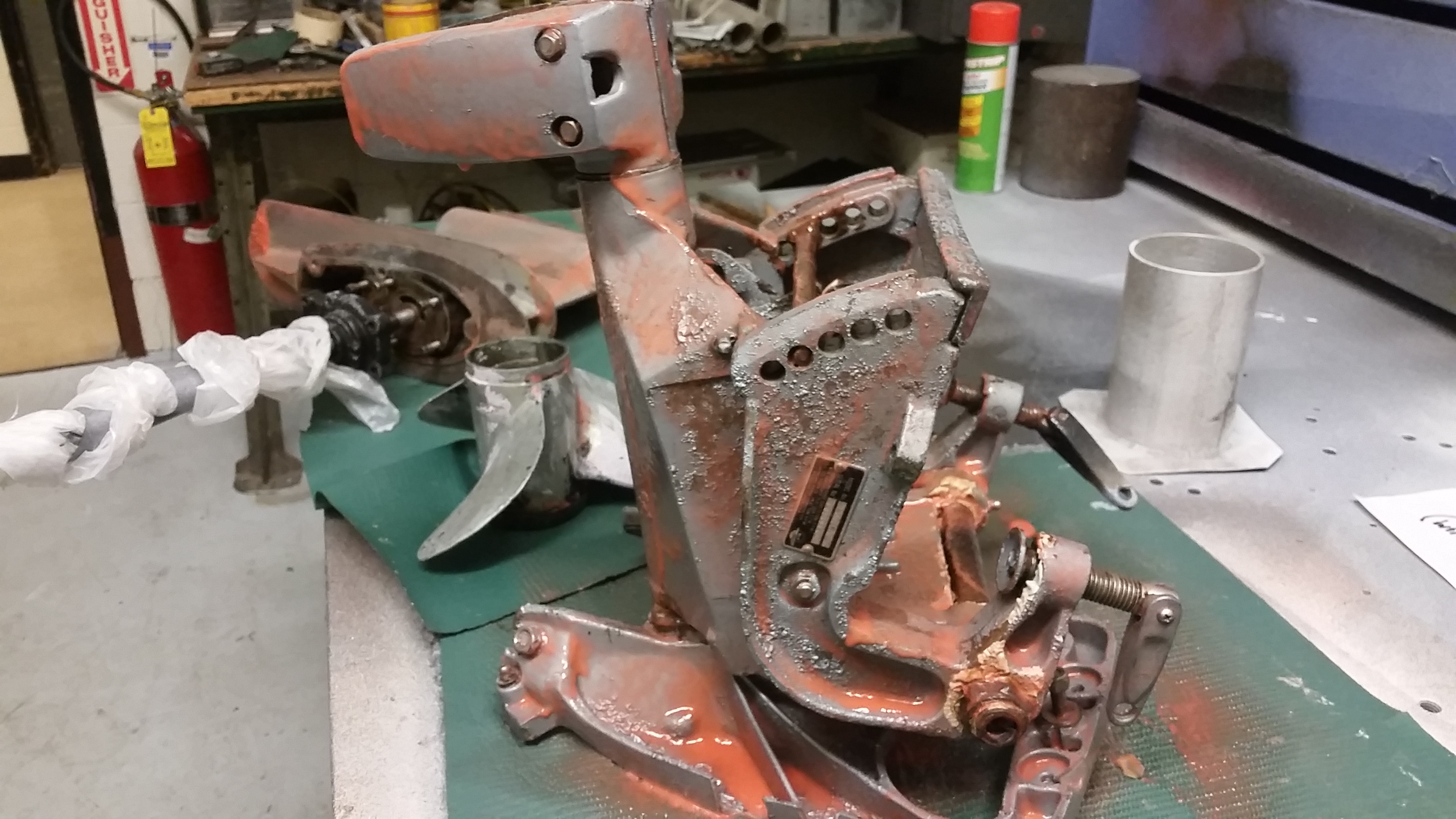
stared at. Ooof Its worse than I recalled. Fast forward ~6 months,
the outboard with the very sad engine had been sitting
in a stairwell. Now that it was summer I began
plotting power boating. Time to re-evaluate 'free
giant outboard'. It was dragged onto the bench and
stared at. Ooof Its worse than I recalled. |
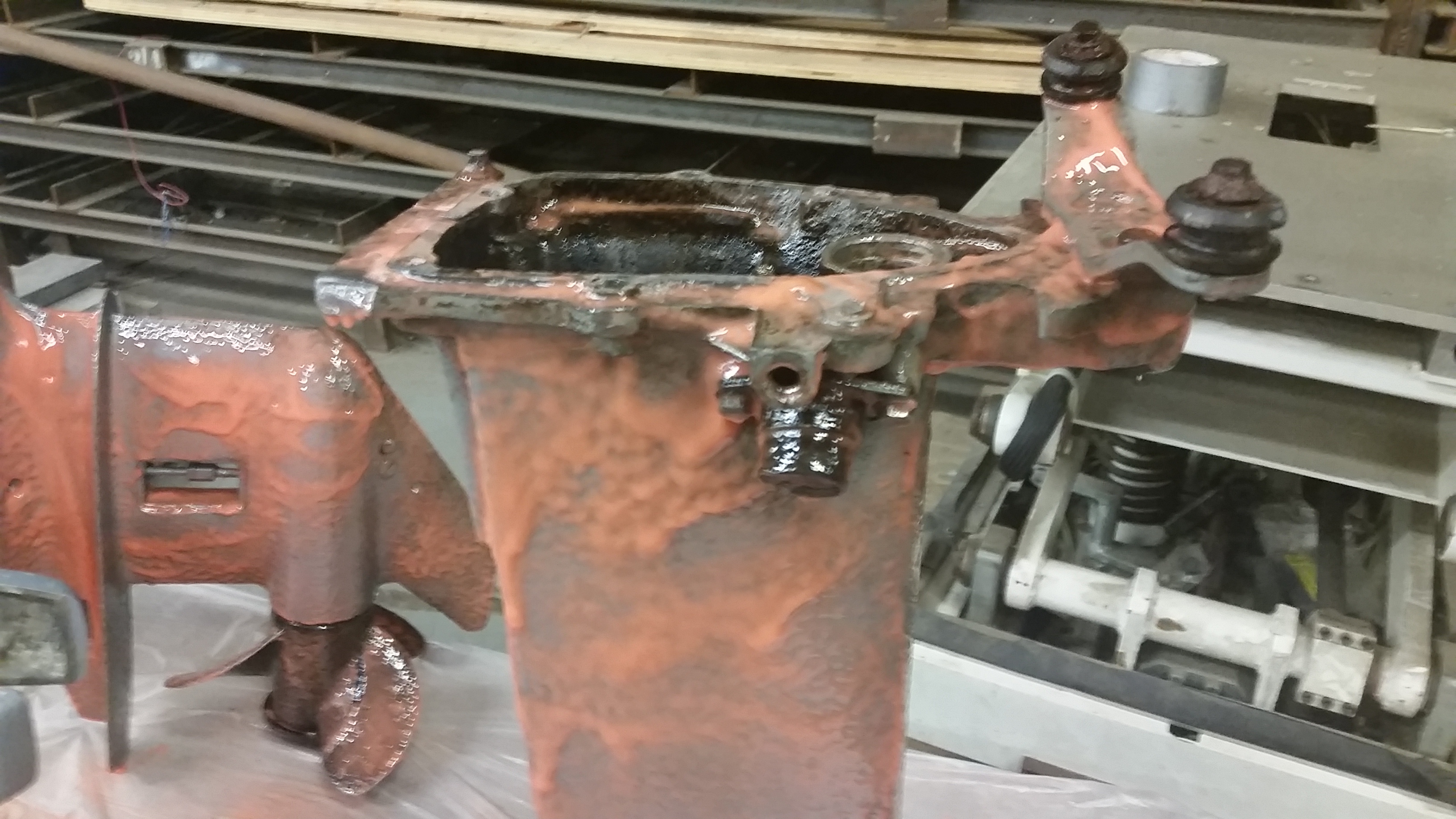
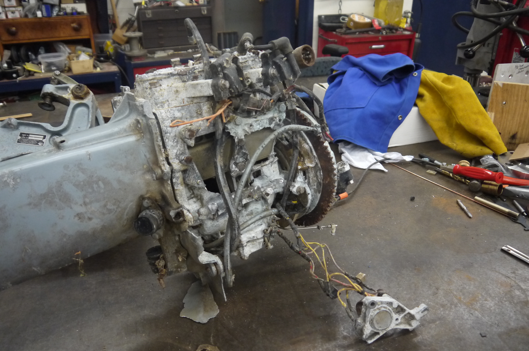  The hammer blows are all
the more visible here, a significant amount of force
was applied. That engine was really stuck in place,
prying with crowbars, vibrating with power drivers,
nothing budged this thing. We all took out
frustrations with sledgehammer blows of varying angle
of attack. Corrosion is quite a bother. The hammer blows are all
the more visible here, a significant amount of force
was applied. That engine was really stuck in place,
prying with crowbars, vibrating with power drivers,
nothing budged this thing. We all took out
frustrations with sledgehammer blows of varying angle
of attack. Corrosion is quite a bother. |
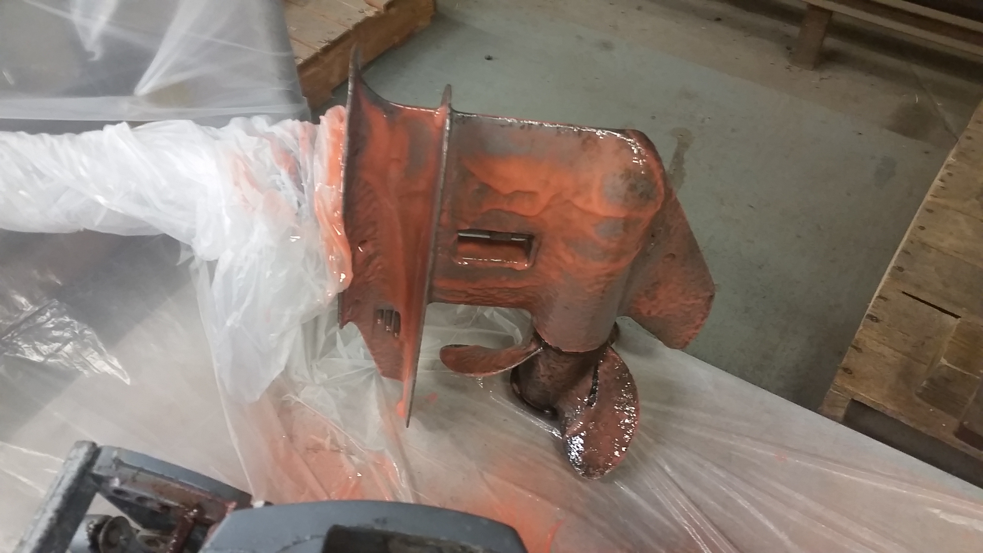
  The
question kept popping up, how did it get so corroded? I
seriously am a befoogled. Its almost as if it was
planted upside down in the soil, in order to grow more
outboards. Bizarre. The
question kept popping up, how did it get so corroded? I
seriously am a befoogled. Its almost as if it was
planted upside down in the soil, in order to grow more
outboards. Bizarre. |
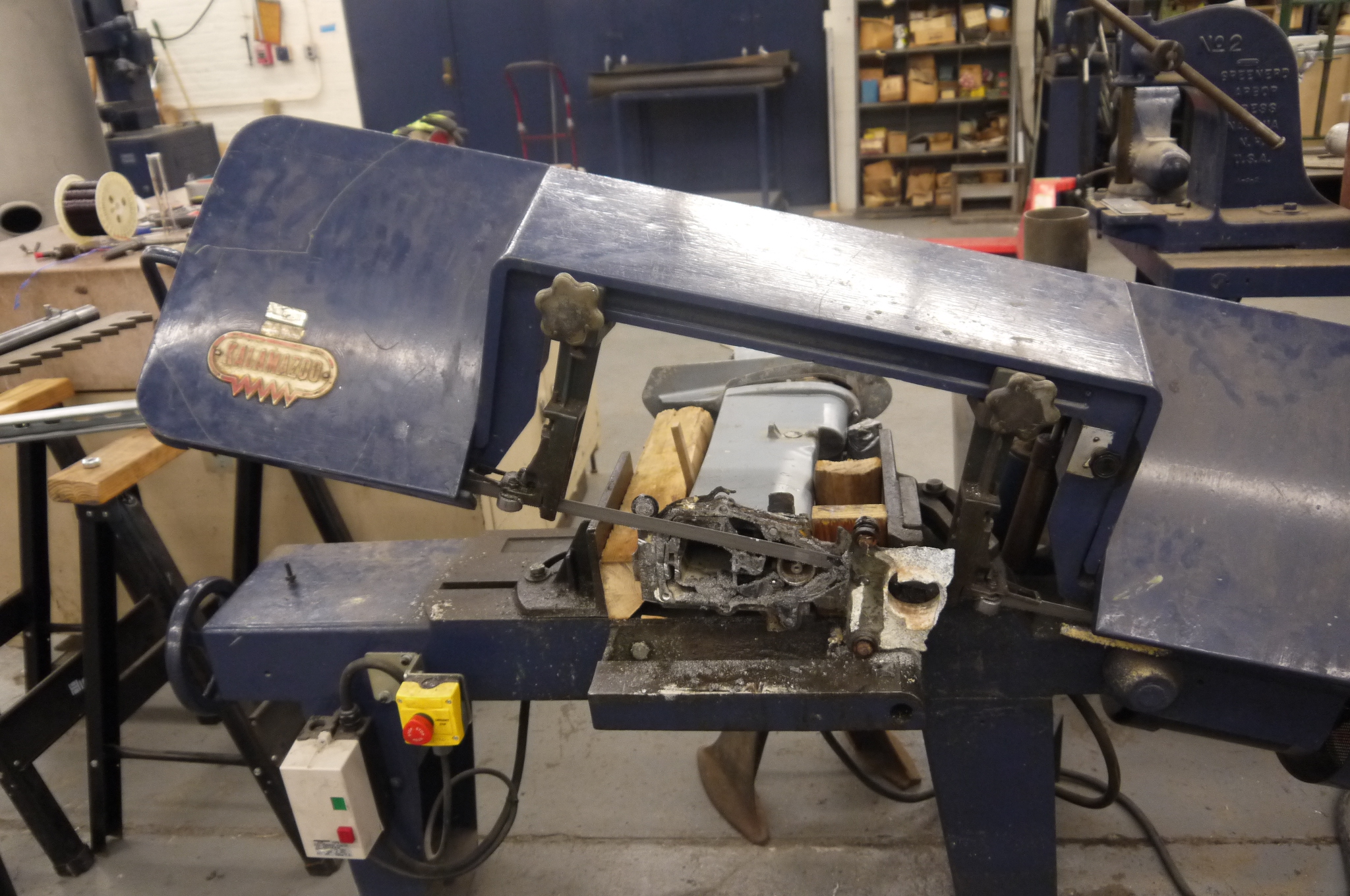
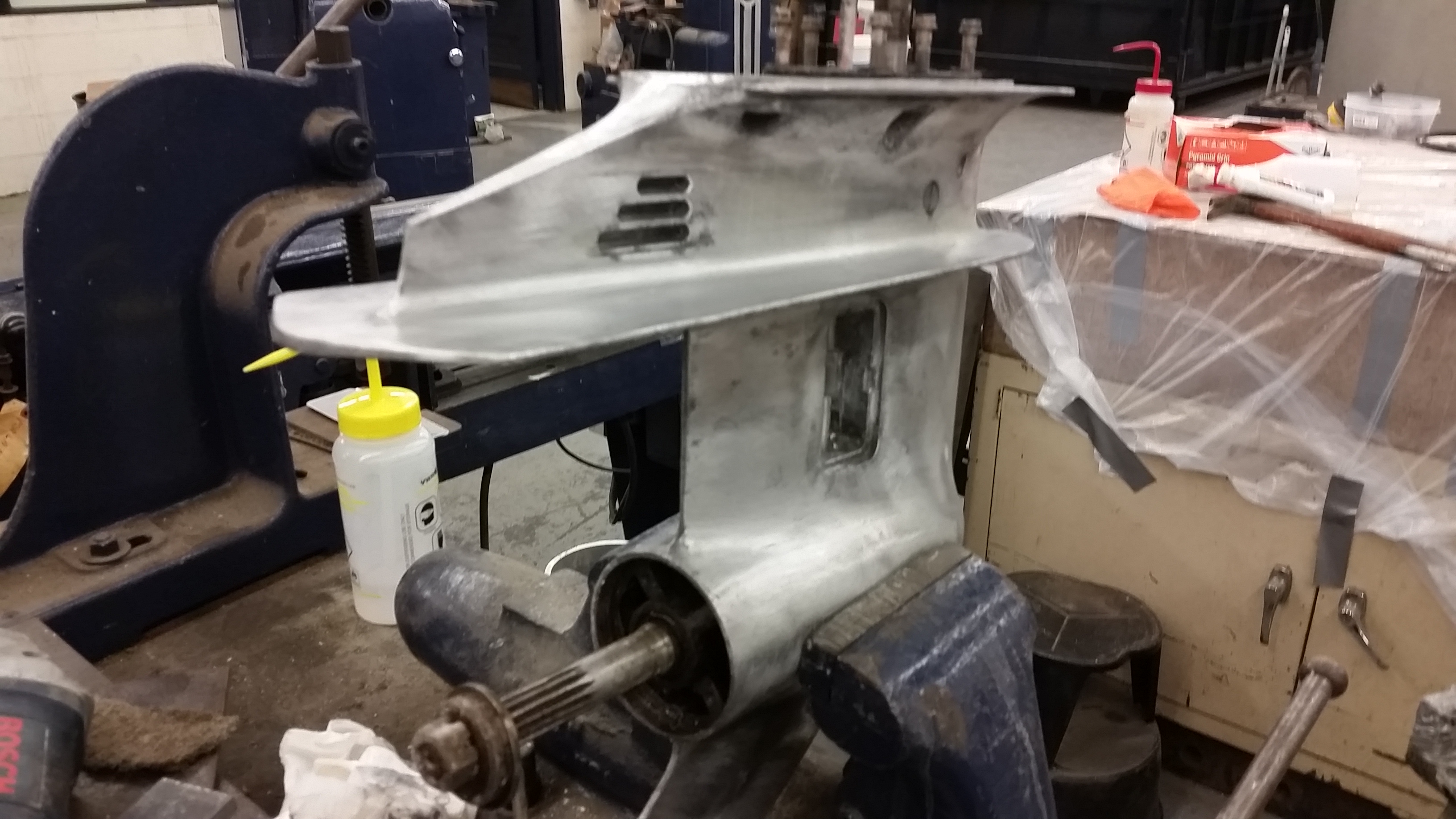
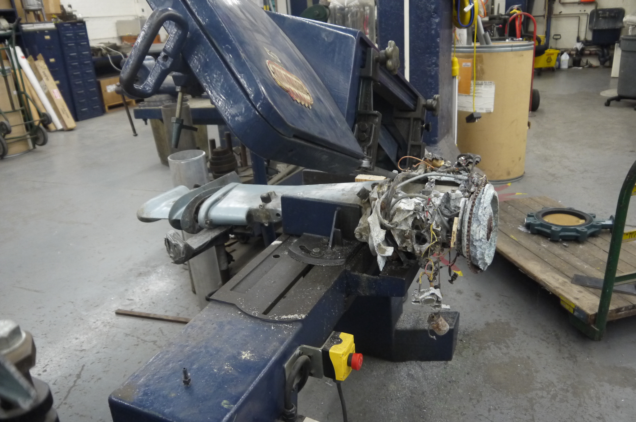 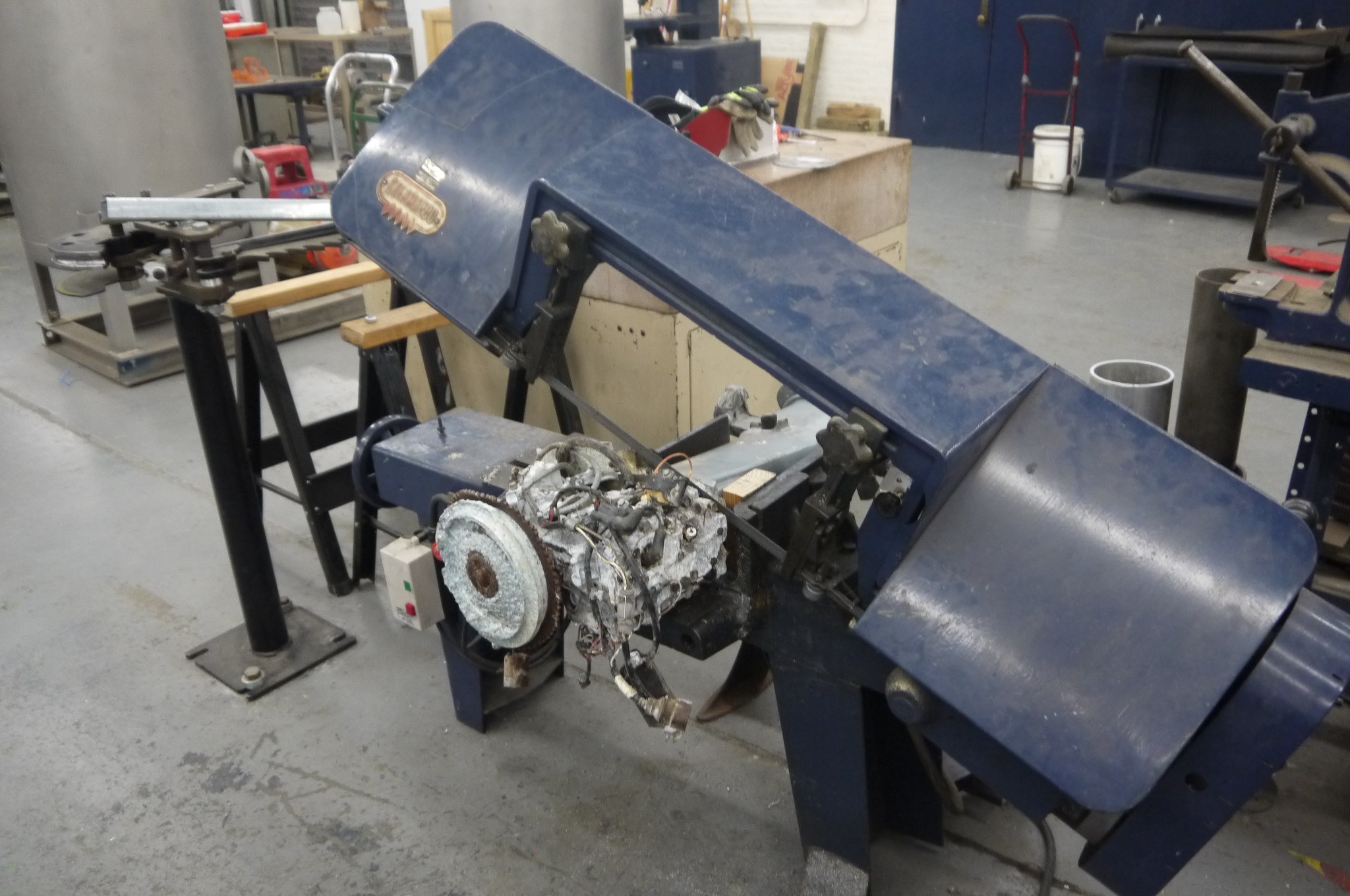 ENTER GIANT BAND SAW ENTER GIANT BAND SAWThe NRL "absolutely giant band saw" got a chance to show off. The entire outboard fit between it's giant jaws and over the course of 42 minutes the engine and outboard were separated. |
  This
wasn't easy, the outboard itself is 'swoopy' and curvy,
clamping it required some curious wood structures to
capture everything and keep the outboard level. Finally
the outboard was sawed from both sides, flipped over
about 1/3 of the way through from the first cut. This
wasn't easy, the outboard itself is 'swoopy' and curvy,
clamping it required some curious wood structures to
capture everything and keep the outboard level. Finally
the outboard was sawed from both sides, flipped over
about 1/3 of the way through from the first cut. |
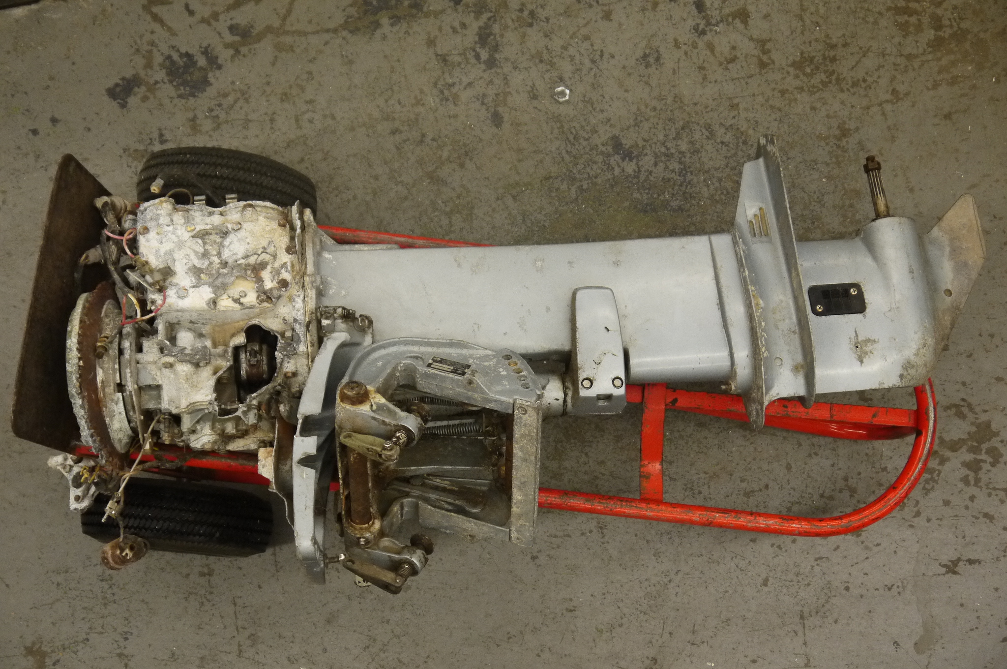
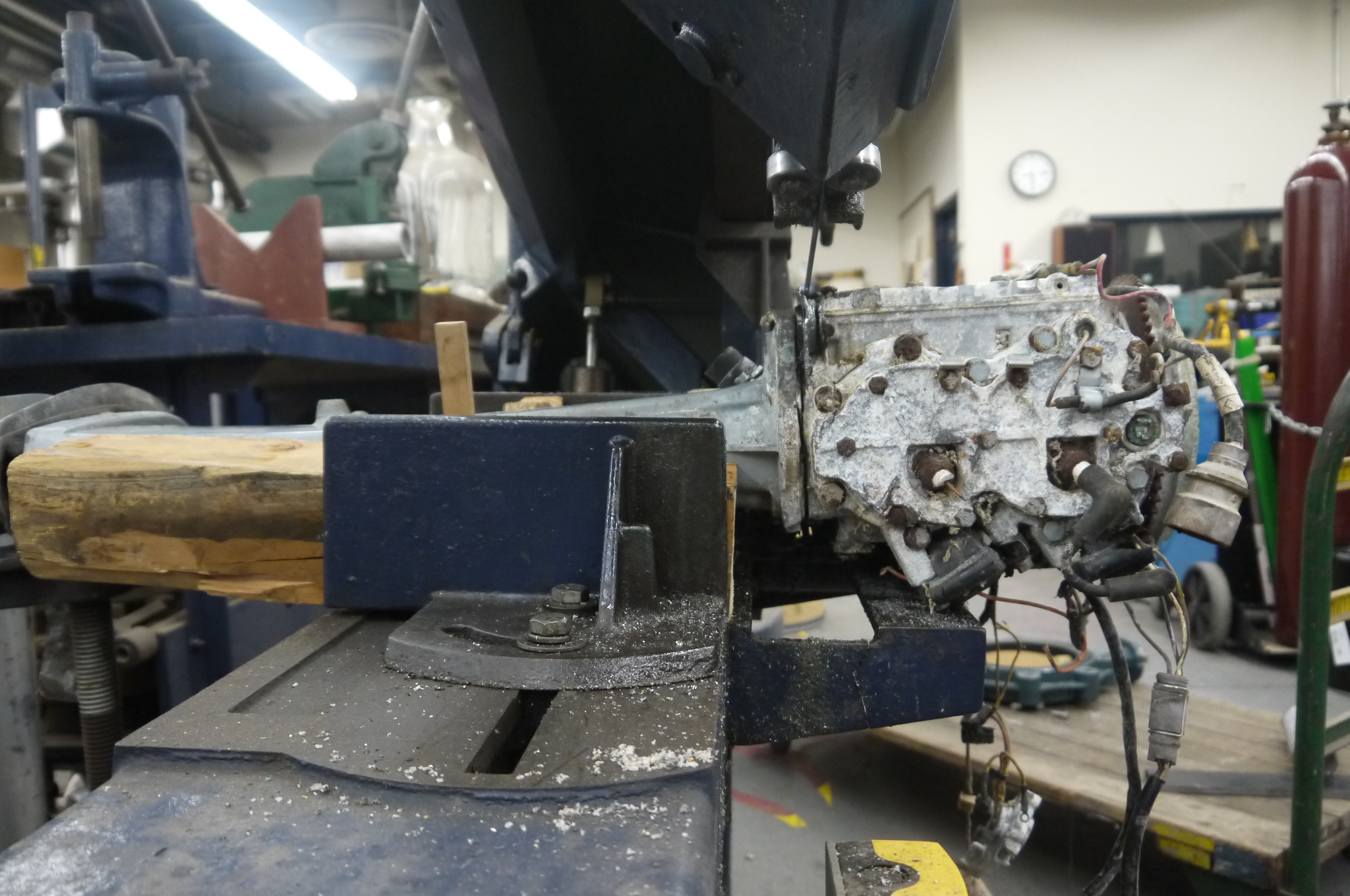
 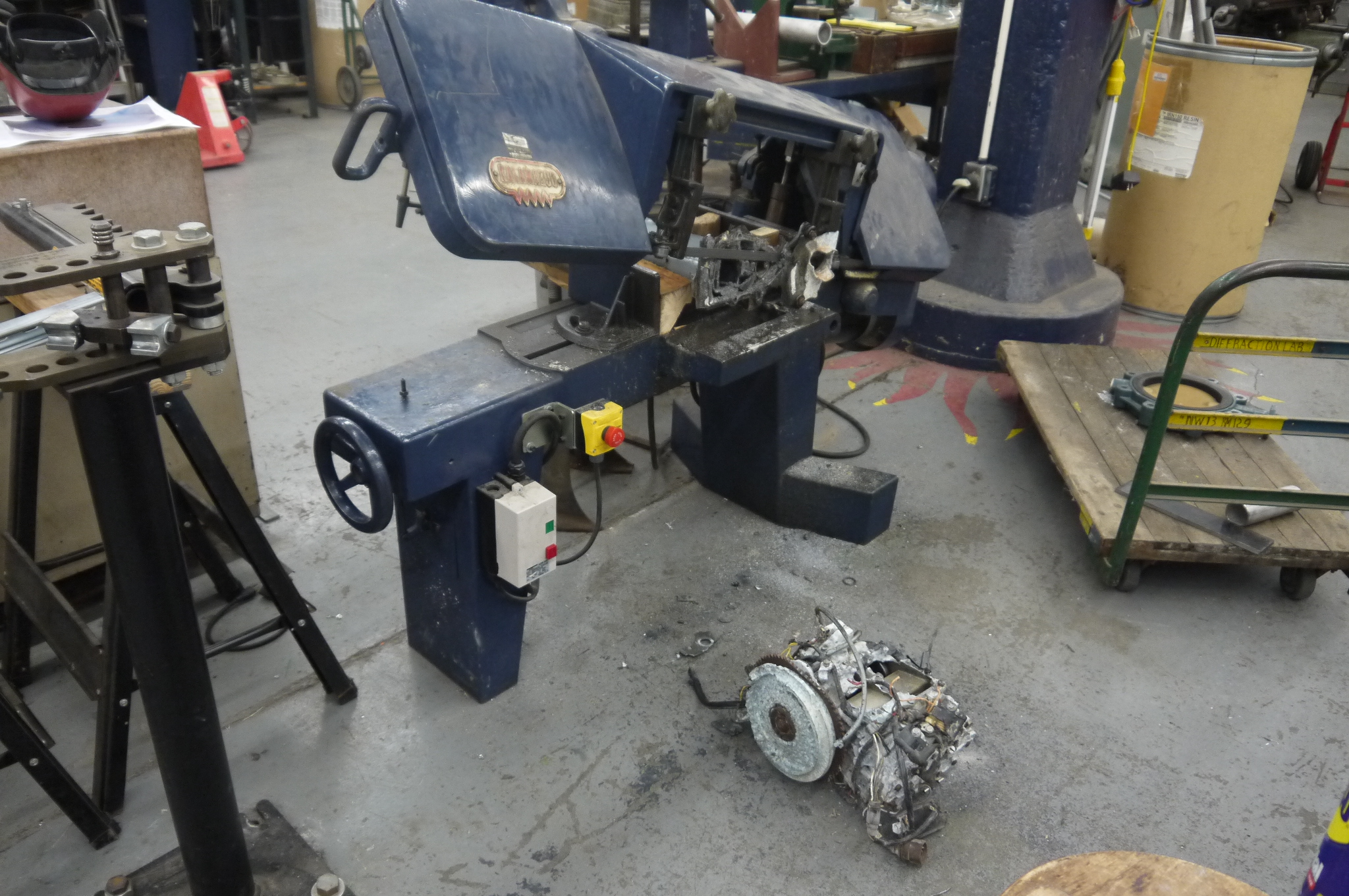 42 long minutes later 42 long minutes laterThe outboard engine was removed. I was really concerned about the hardened shaft between the engine and the outboard, but fortunately tugging and loosening from the propeller end of the outboard really helped things. |
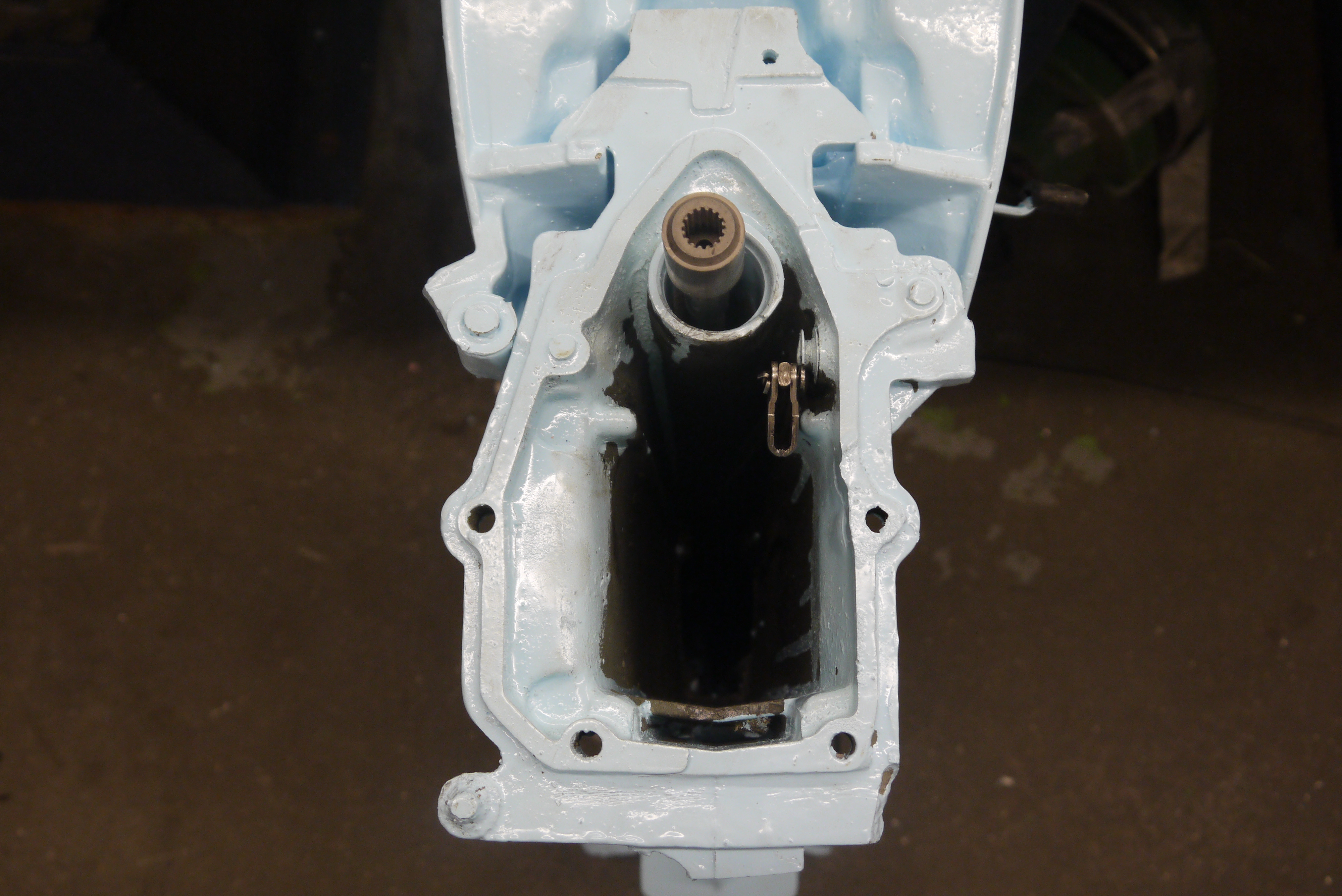
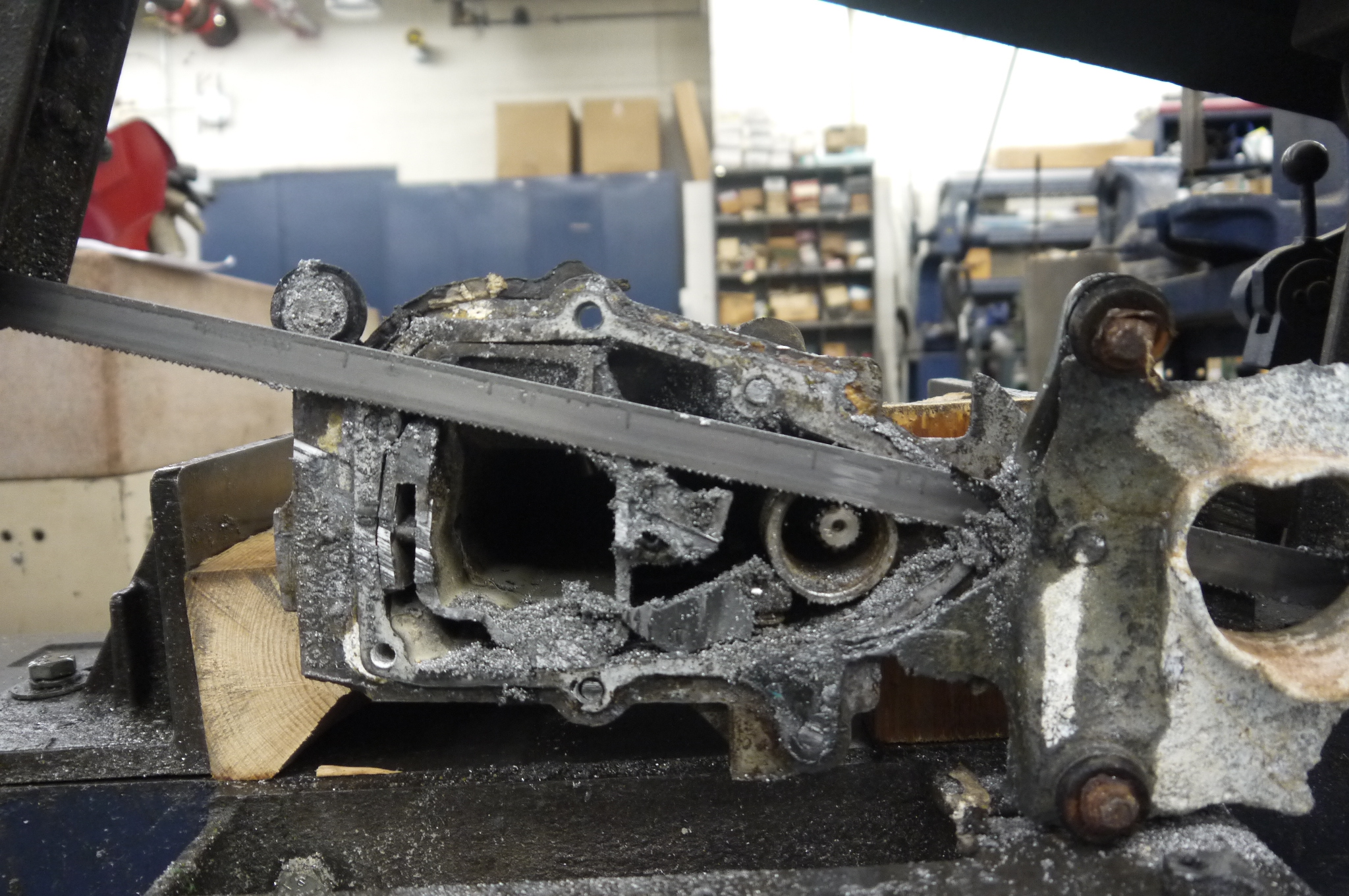  Look at that for a second. Look at that for a second.The saw was about 1/8 of an inch from the shaft and cut just in the right spot. Quite excellent! Welcome to the outboard cross section. |
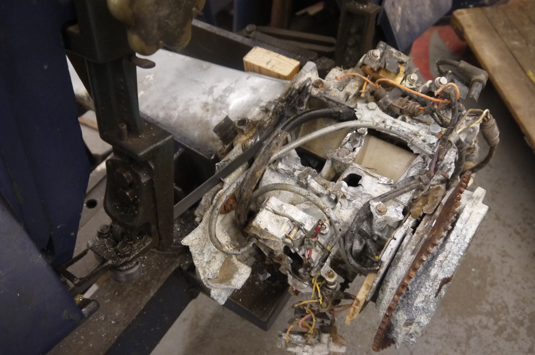
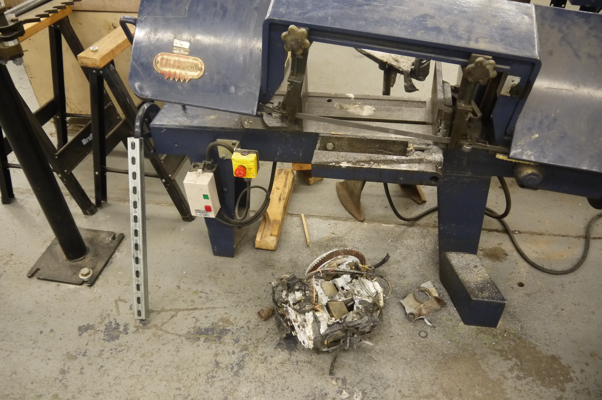 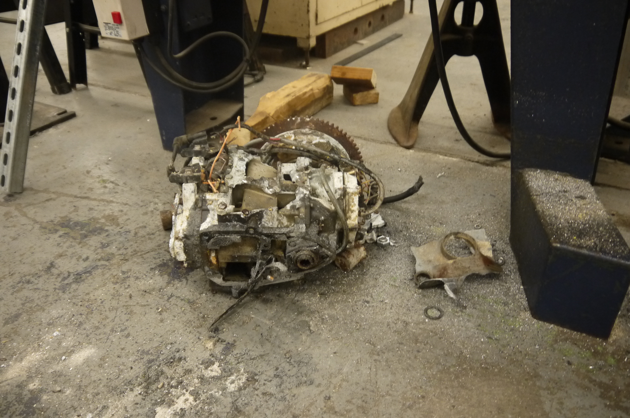 THUD THUDThe un-supported engine remnants clonked onto the floor and were heaved into a recycling dumpster. Nothing immediately identifiable was worth anything, the mating spline appeared to be directly welded to the engine assembly. |
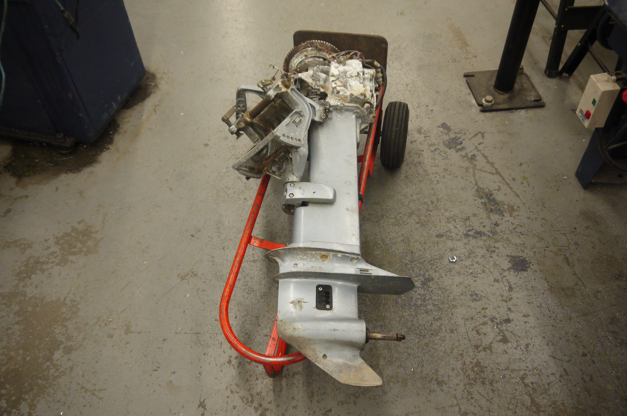
 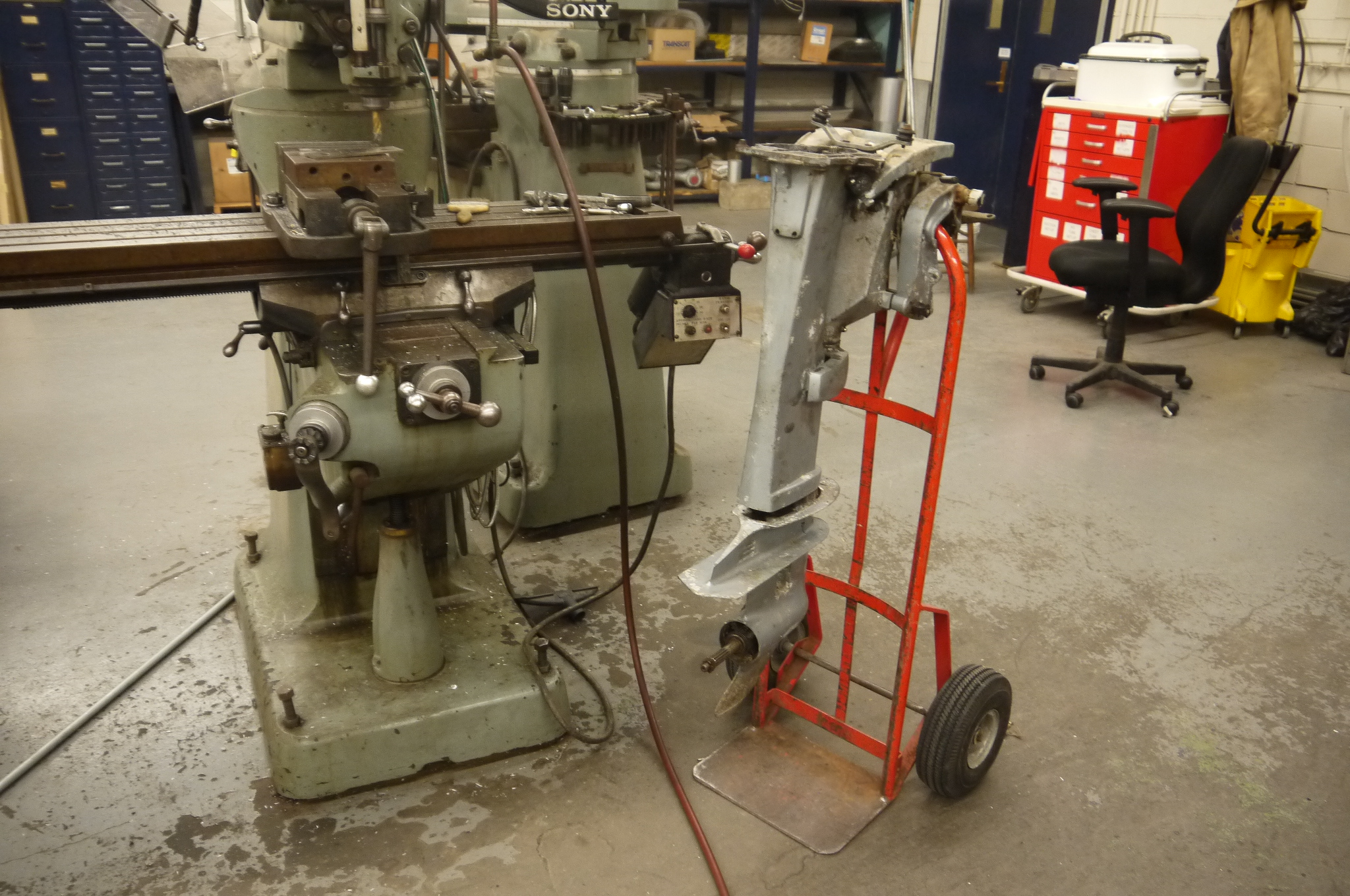 Outboard on a hand truck. Outboard on a hand truck.Behold a long shaft outboard on a hand truck. Time for some motor plotting. There are some options here, given that this particular outboard was rated for a 26kw engine, there is plenty of room for either high rpm automotive alternators (Buick lacrosse hybrid motor) or even the famed go kart 'alter-moter' used in the miters go kart. plenty of options afoot, but ideally keeping the mass and complexity down would be ideal. 'Debugging at sea' is not advisable. |
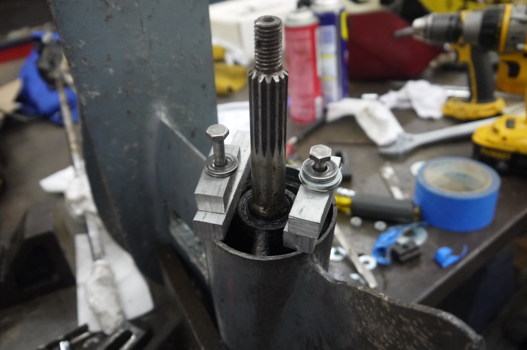
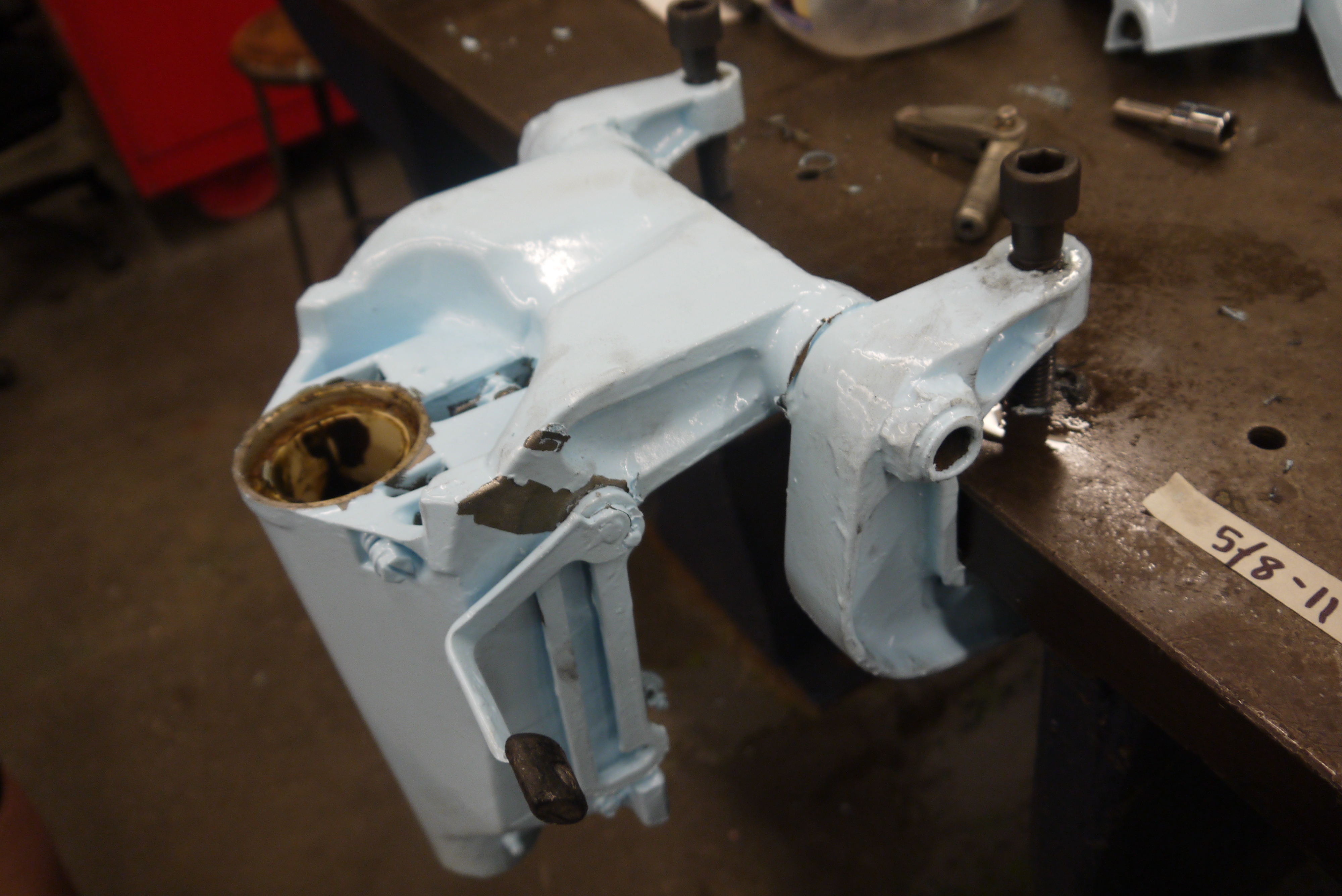
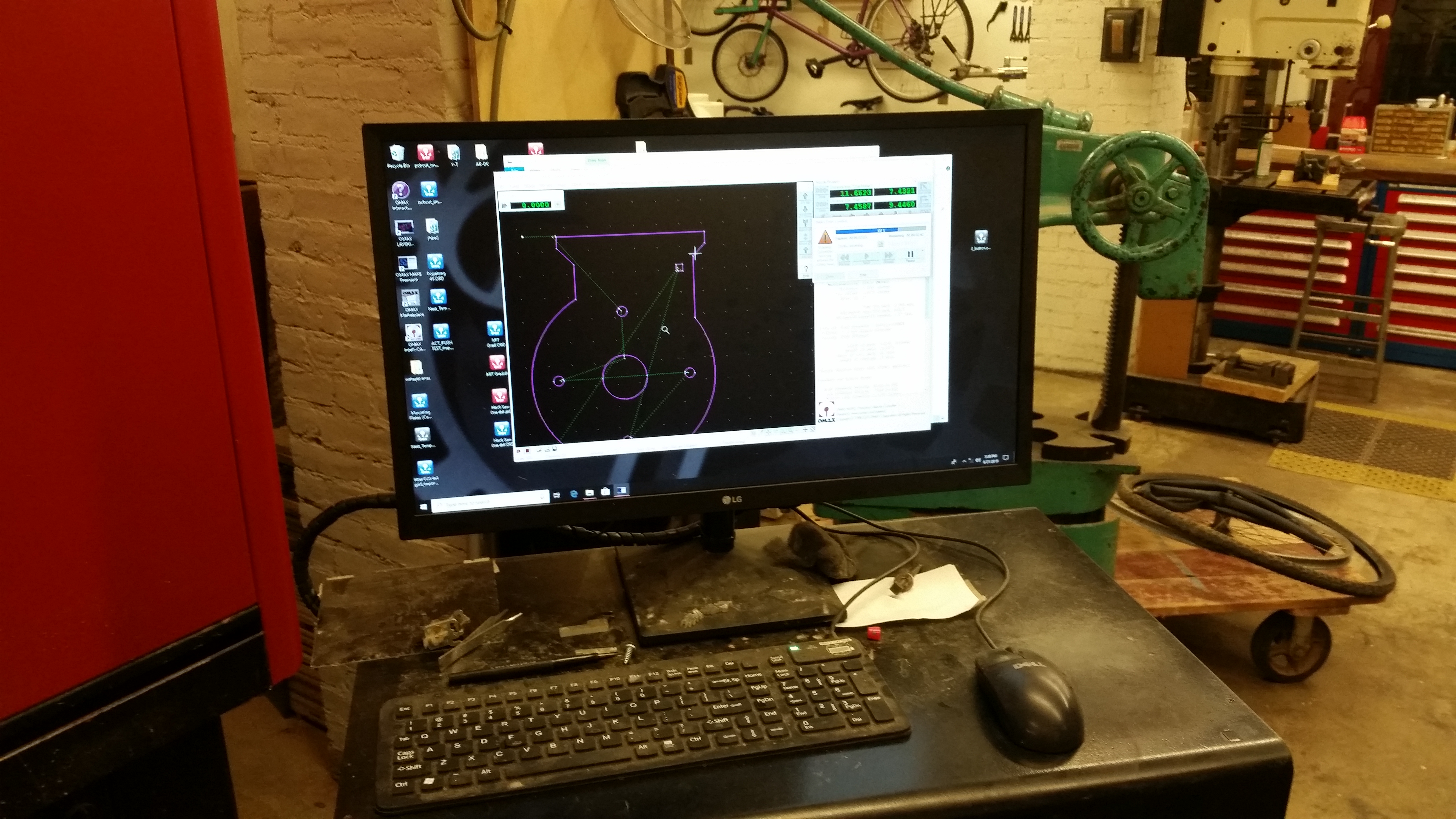
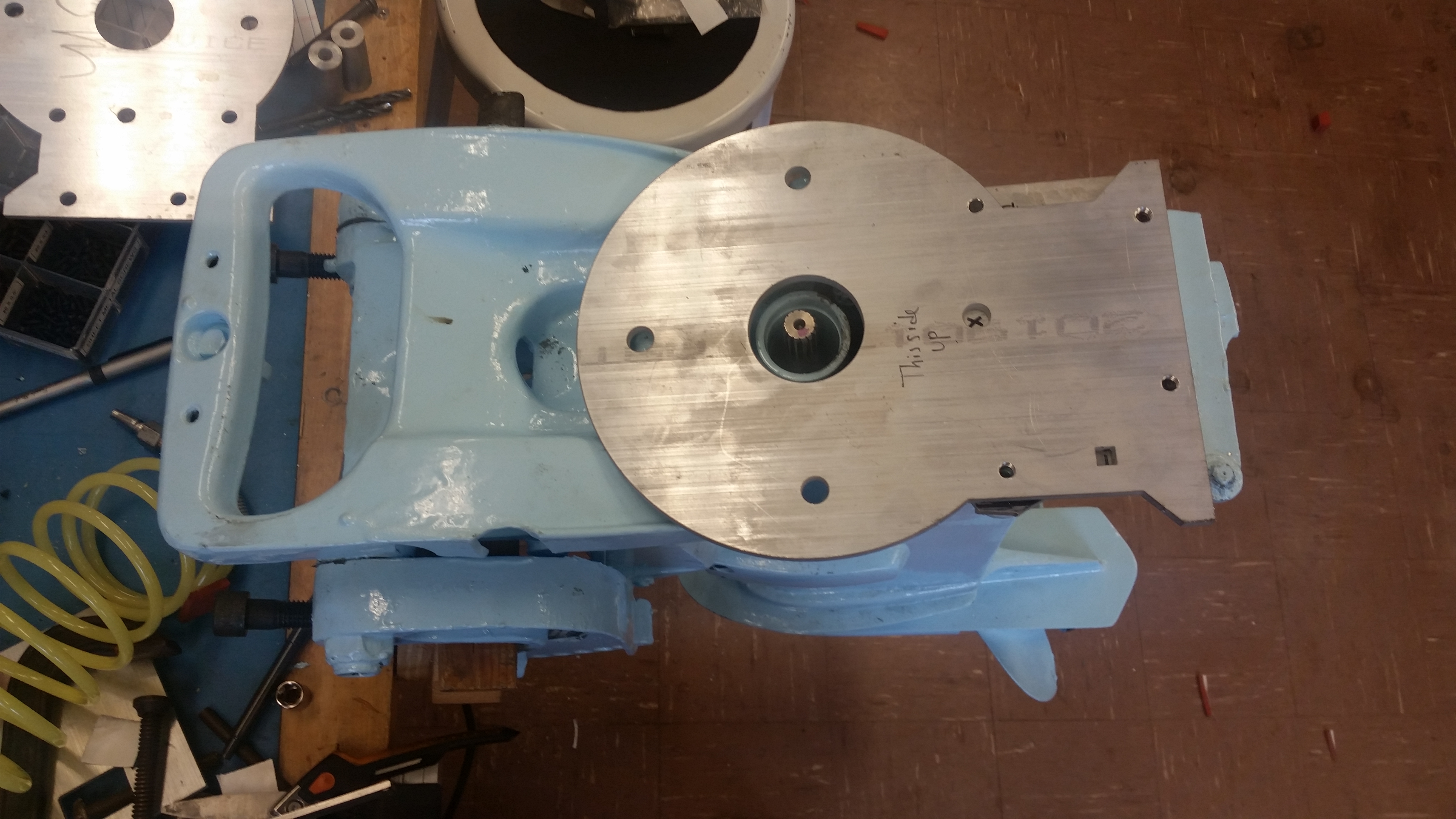
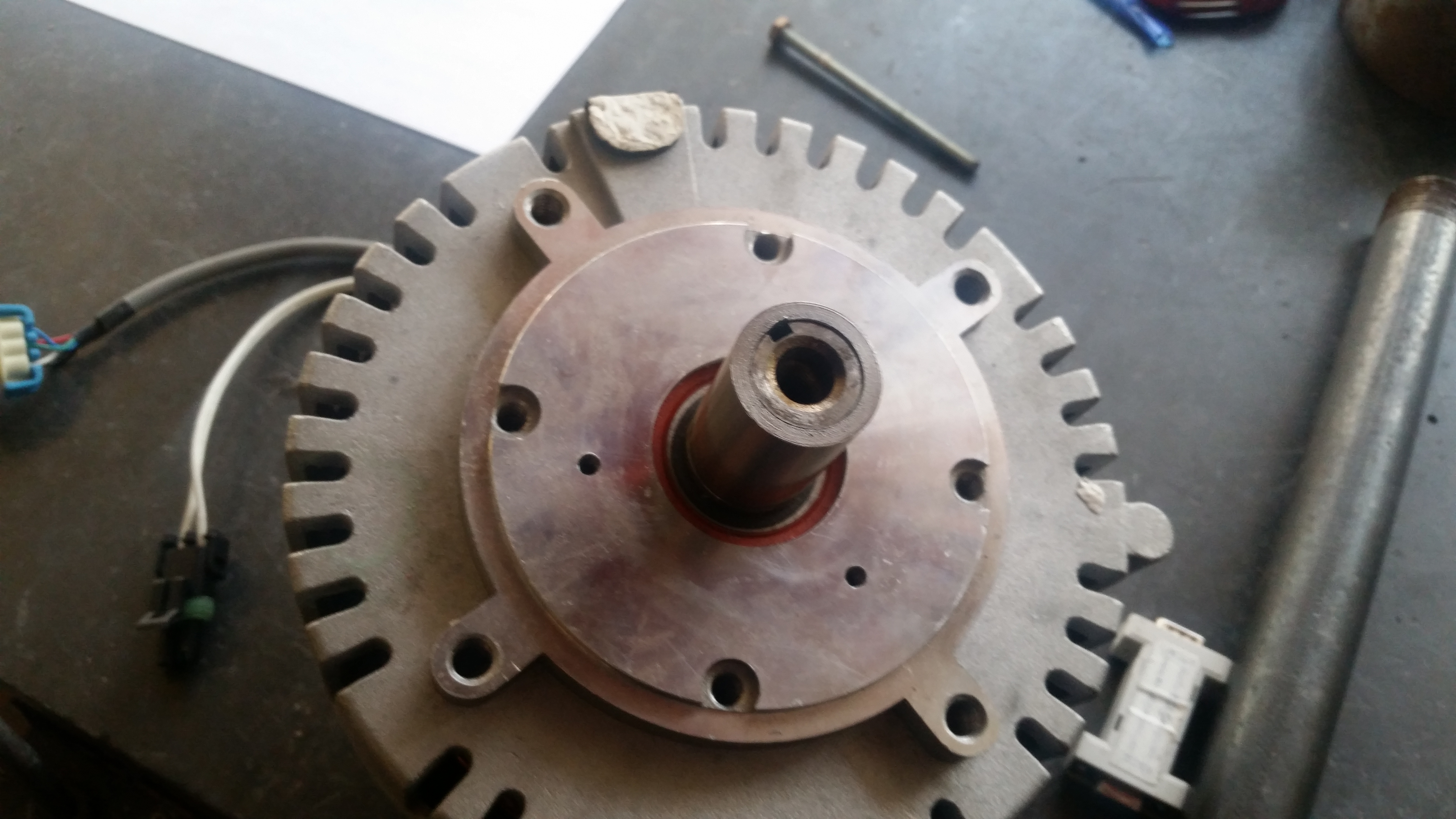
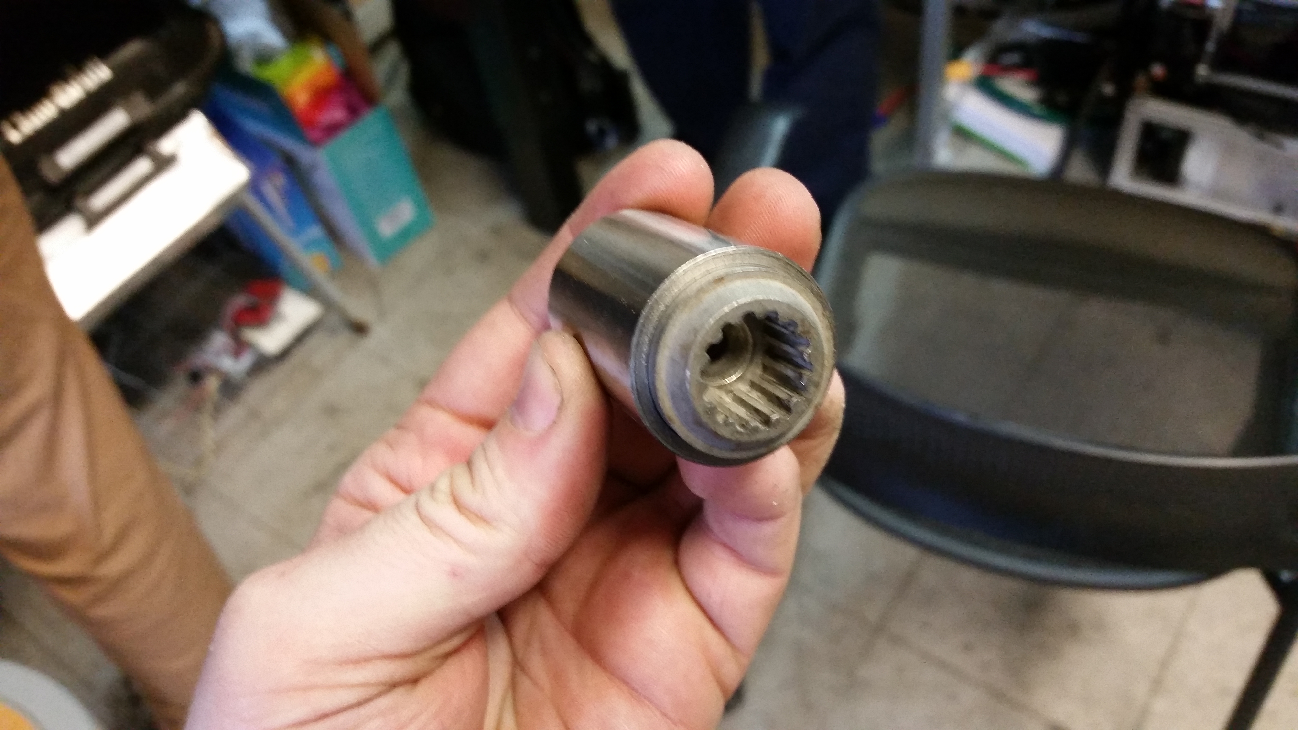
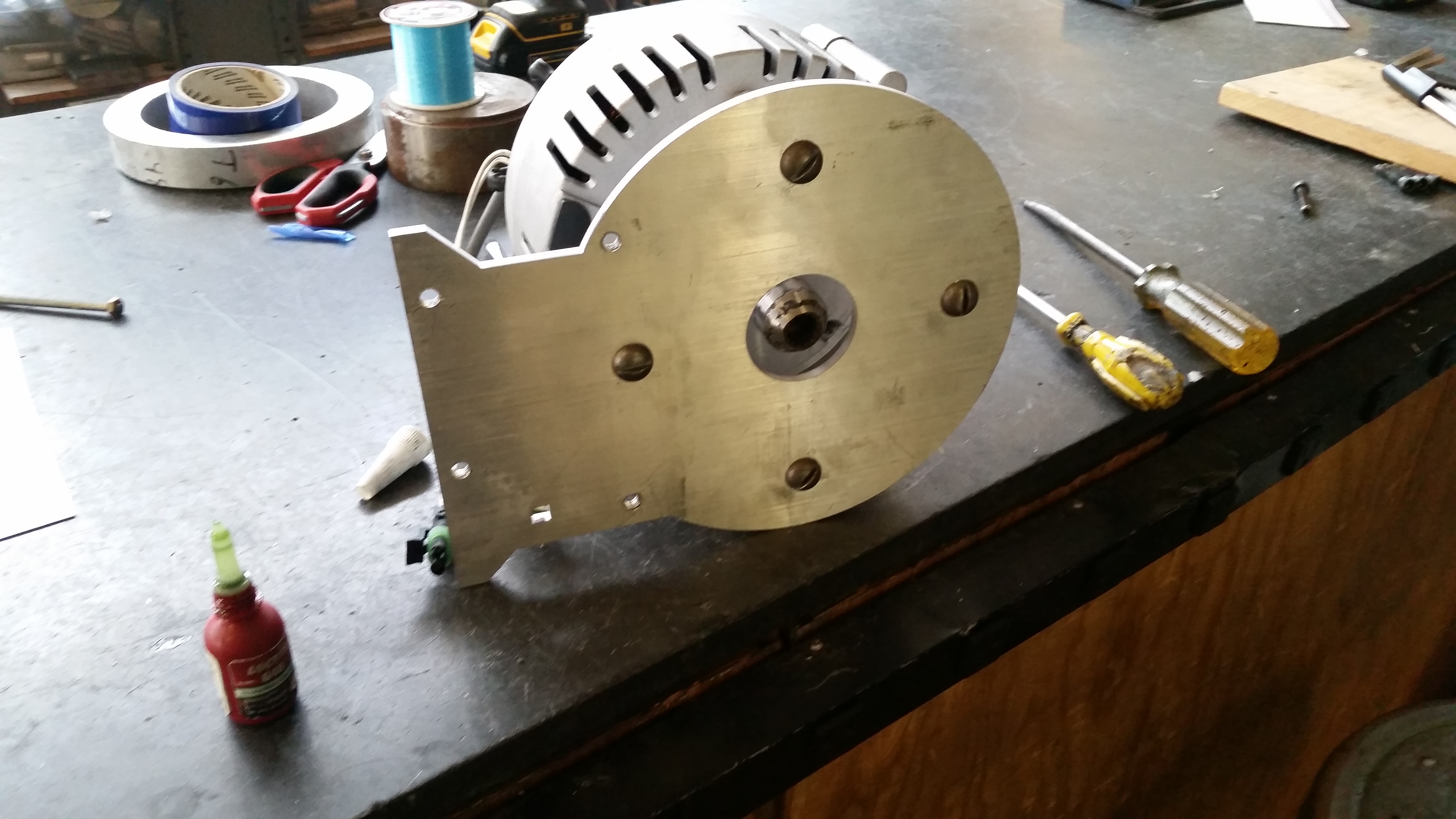
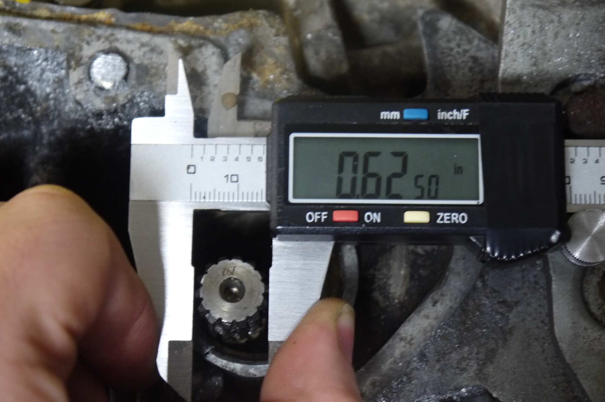  With
the engine FORCIBLY
removed, I took a look at the shaft. Its a curious size,
5/8 outer diameter - 14 tooth splined shaft. After a few
measurements I generated a water jet cut file for a
homemade adapter. With
the engine FORCIBLY
removed, I took a look at the shaft. Its a curious size,
5/8 outer diameter - 14 tooth splined shaft. After a few
measurements I generated a water jet cut file for a
homemade adapter. |
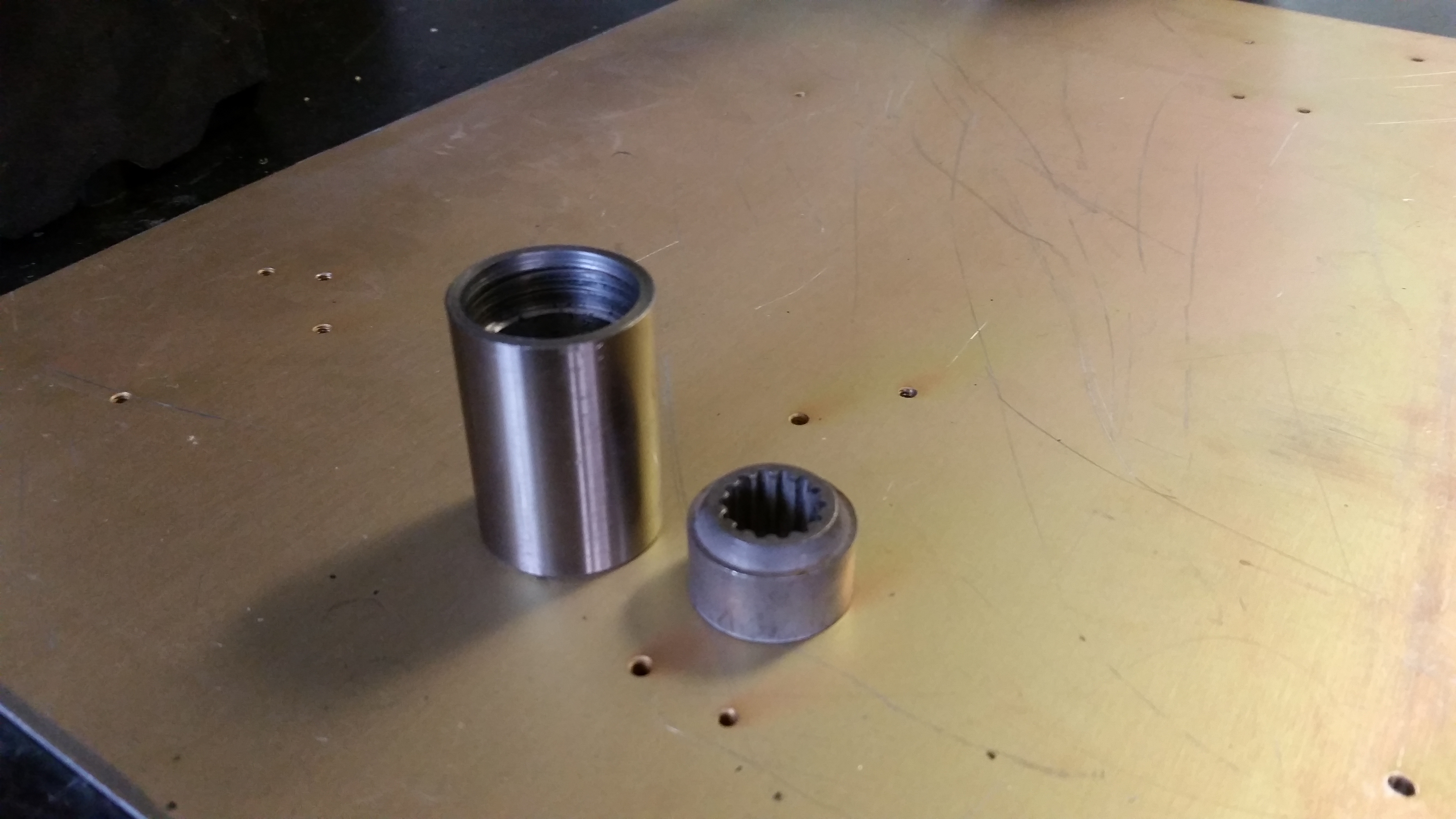
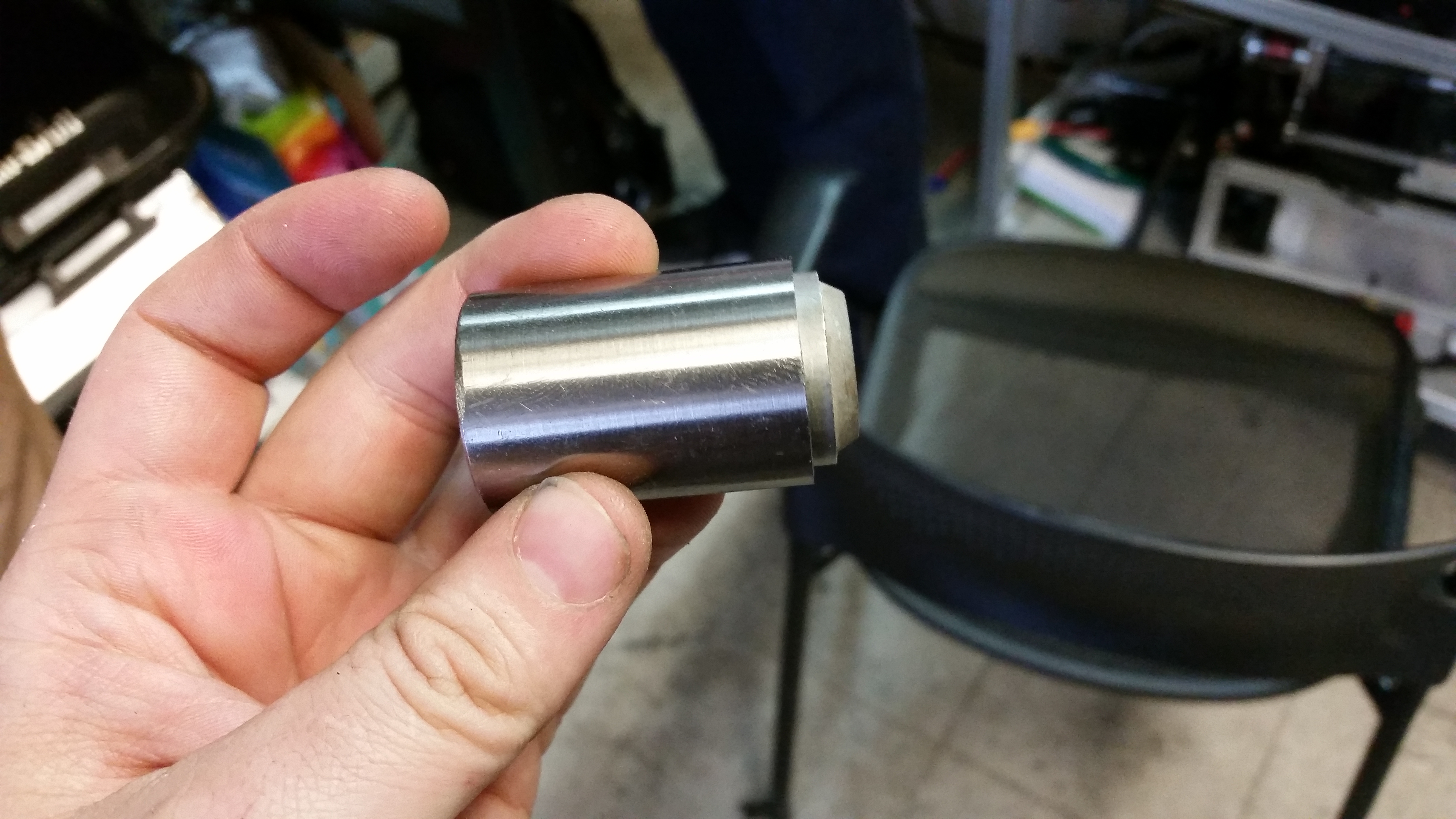
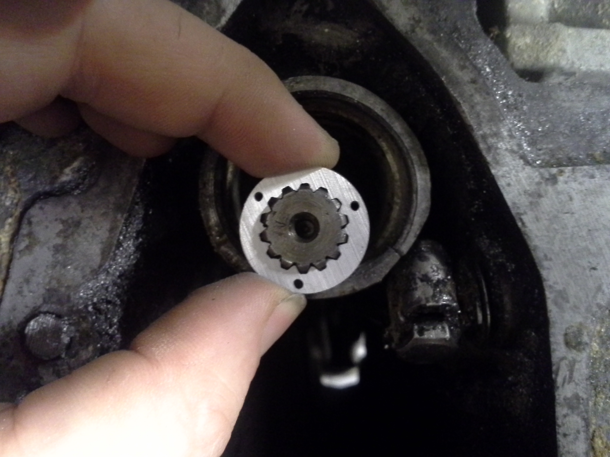 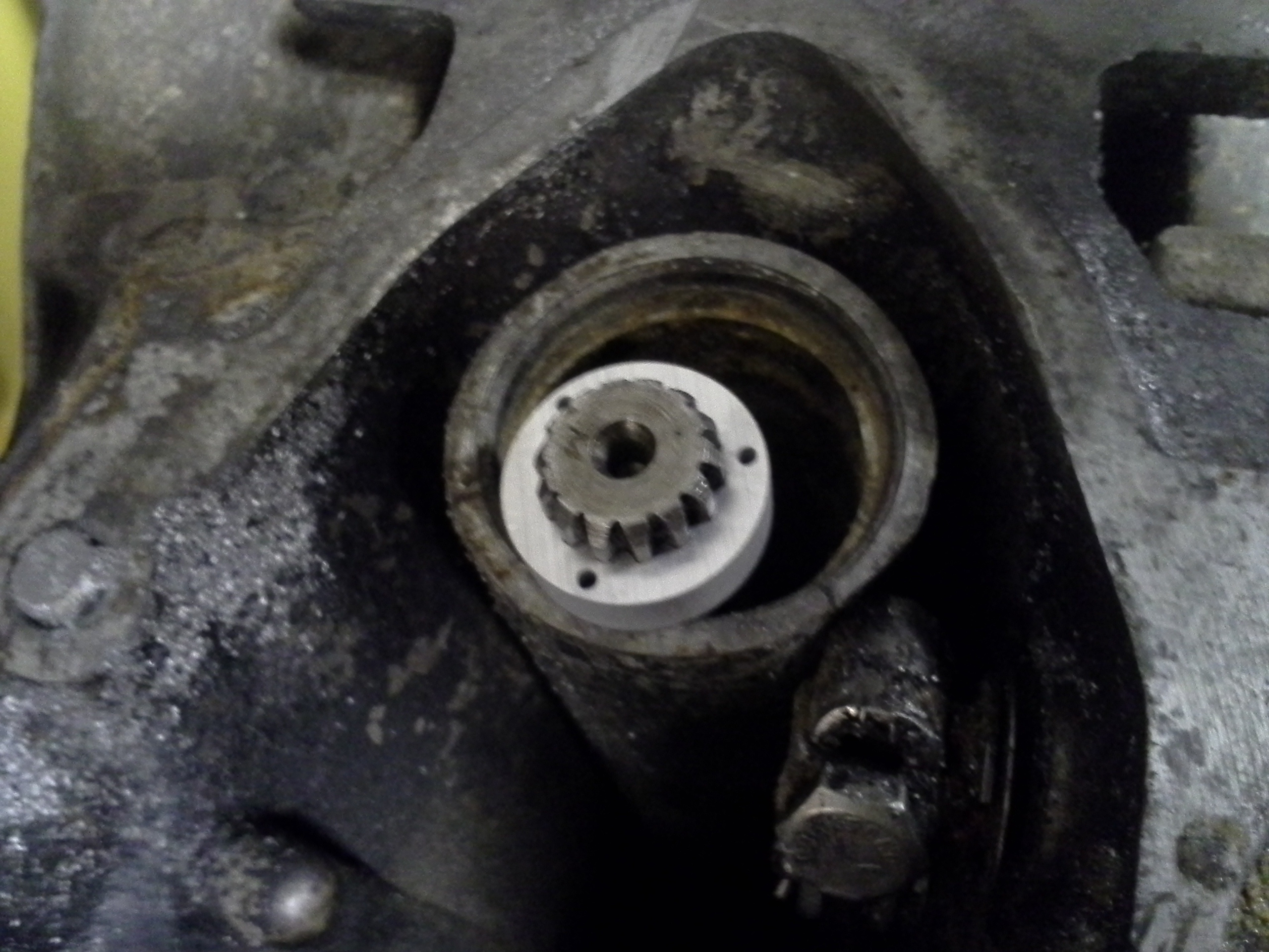 Quite
good! the spline cutout fit great! I used 1/4" thick
6061 aluminum with 3 holes for pins, with a stacked
spline adapter plotted. Very excited when this 'just
fit'. This was going to be a curious one to make an
adapter. I hemmed and hawed about how I wanted to
approach machining this part. Quite
good! the spline cutout fit great! I used 1/4" thick
6061 aluminum with 3 holes for pins, with a stacked
spline adapter plotted. Very excited when this 'just
fit'. This was going to be a curious one to make an
adapter. I hemmed and hawed about how I wanted to
approach machining this part. |
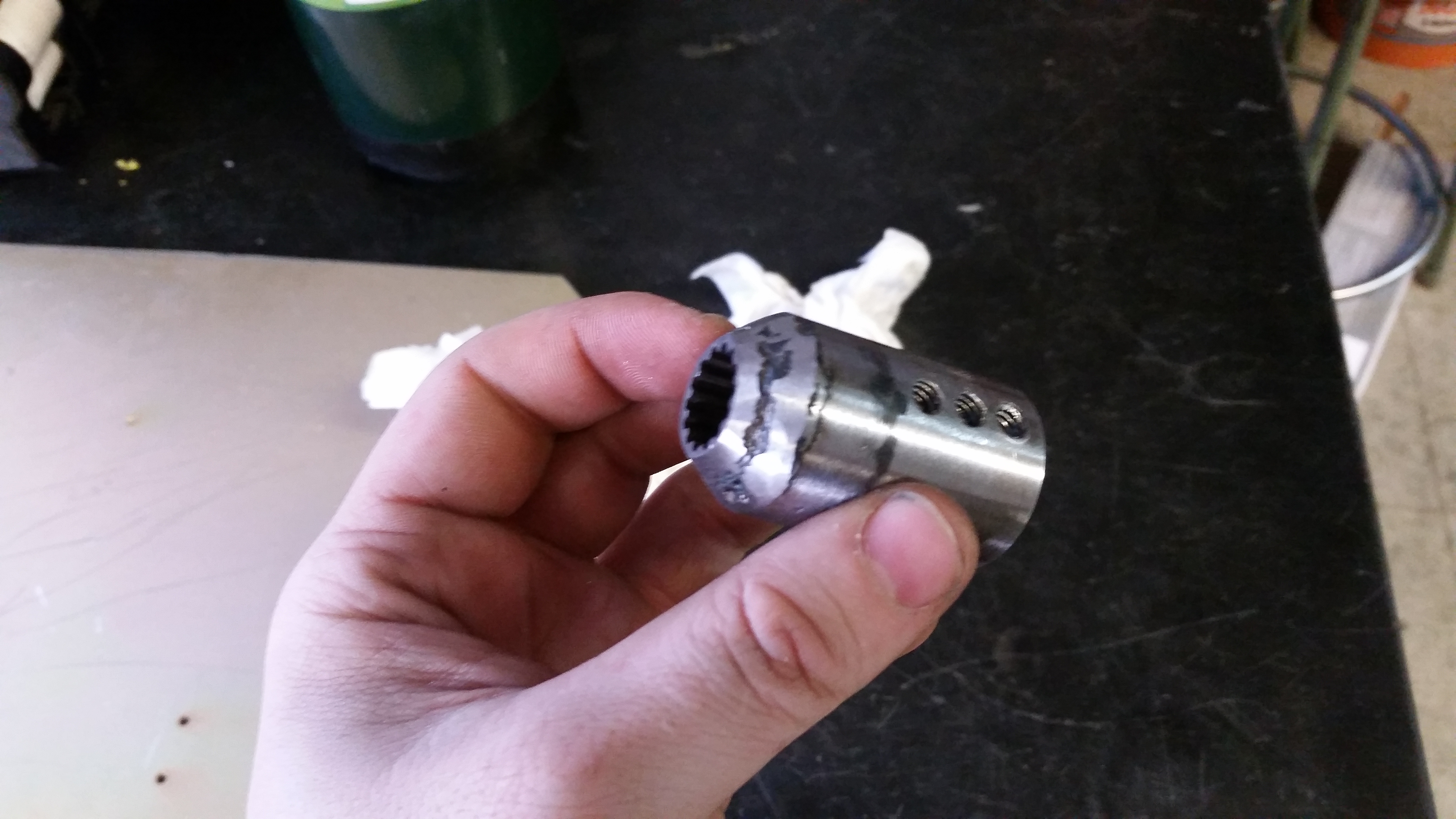
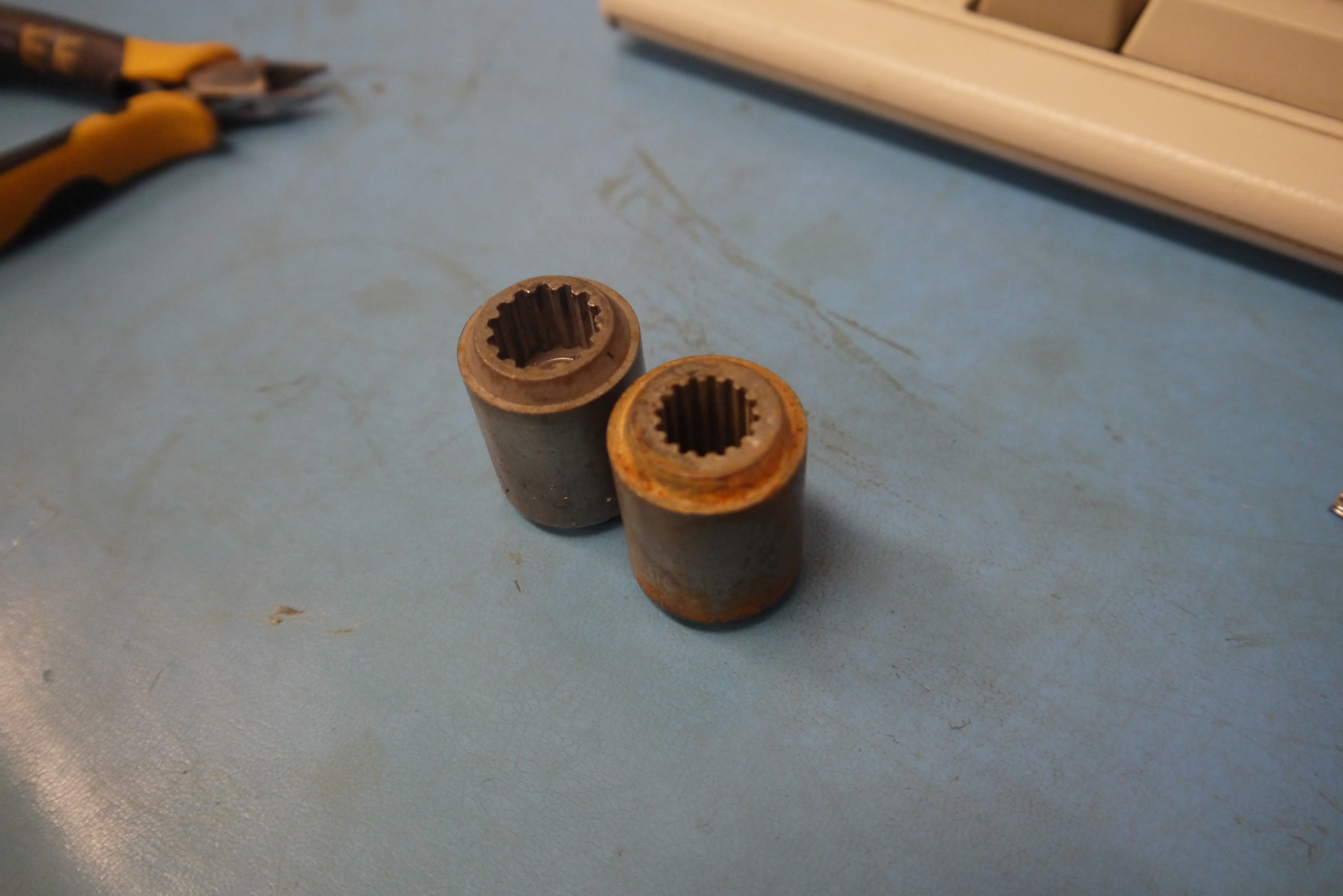  Holey
moleys, are you kidding me, JUST THE RIGHT SPLINE fitting, for quite
cheap. As it turns out ITS EVEN STEEL. I ordered two and
lo, they fit like a glove! excellent! Shown far right
are either side of the splined adapter. Holey
moleys, are you kidding me, JUST THE RIGHT SPLINE fitting, for quite
cheap. As it turns out ITS EVEN STEEL. I ordered two and
lo, they fit like a glove! excellent! Shown far right
are either side of the splined adapter. |
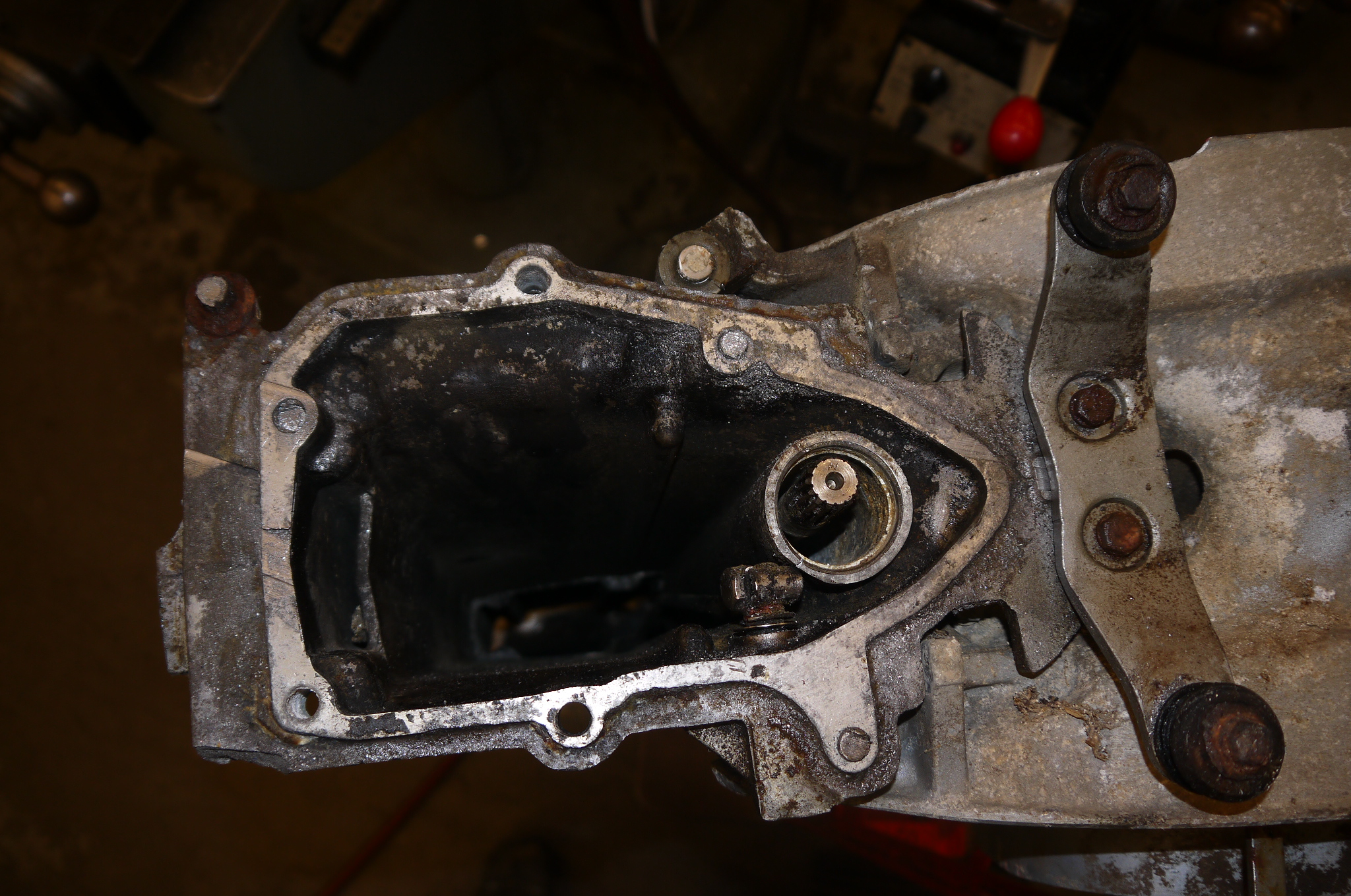
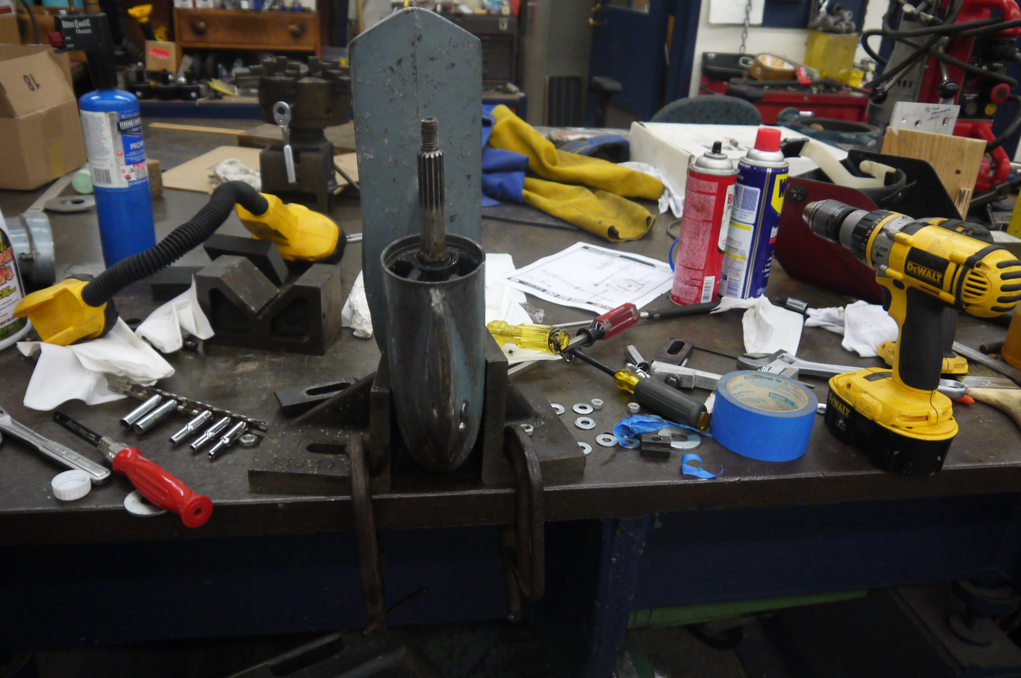
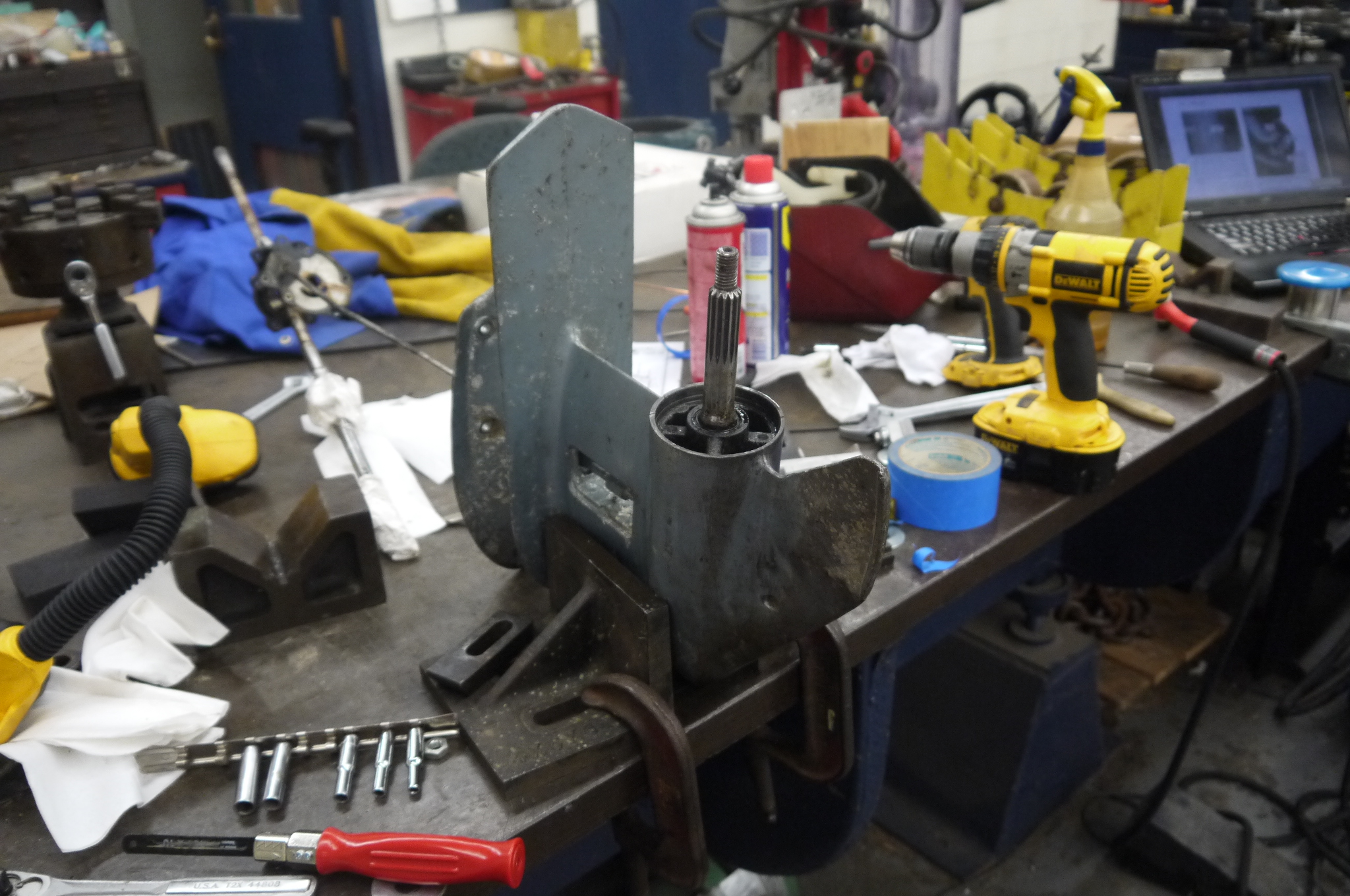
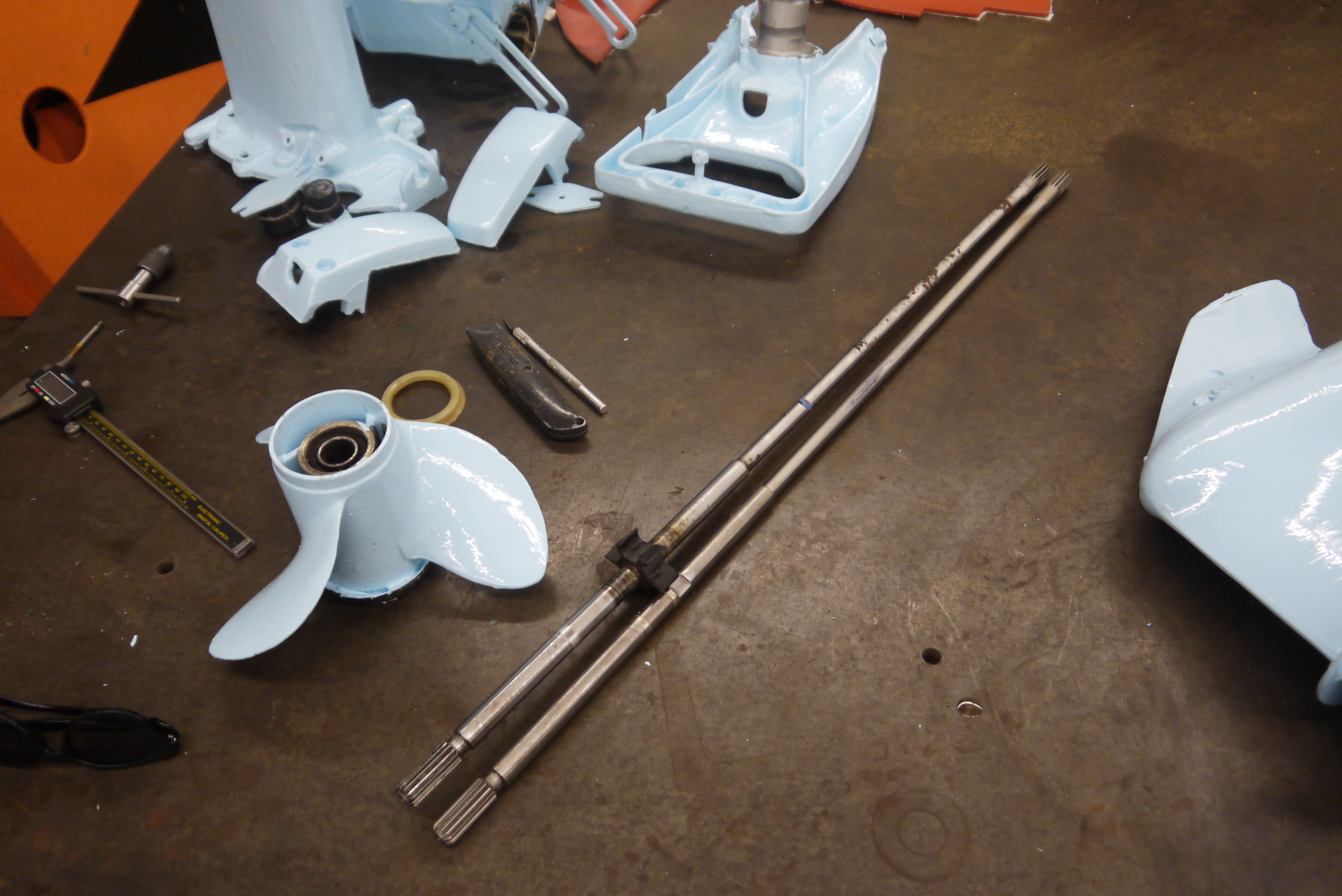
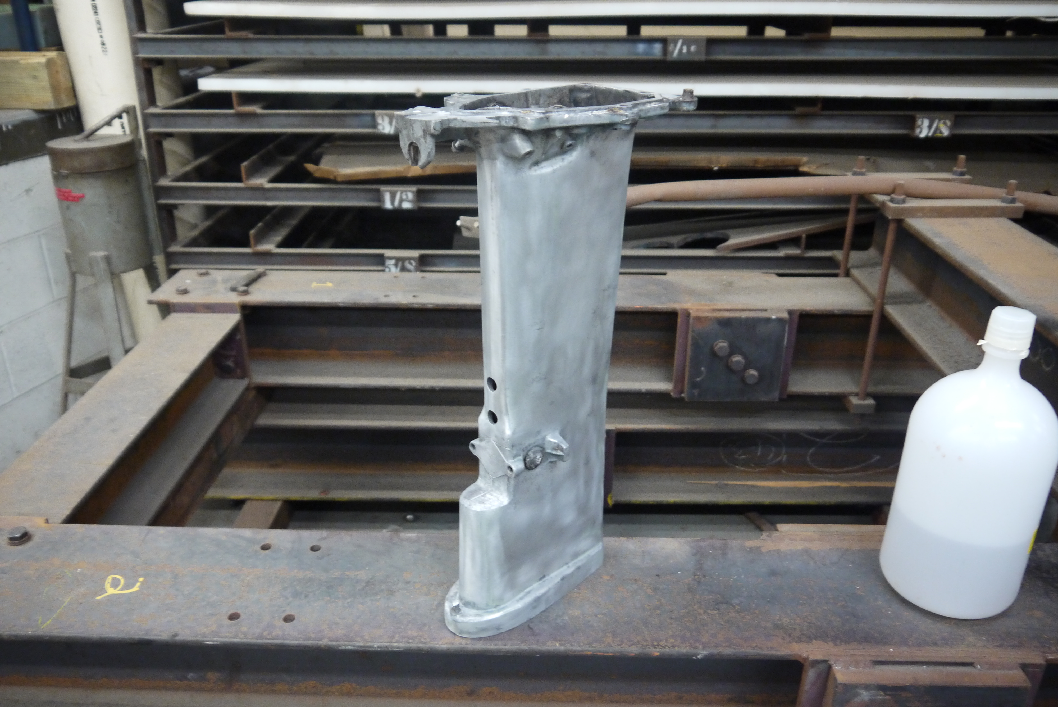
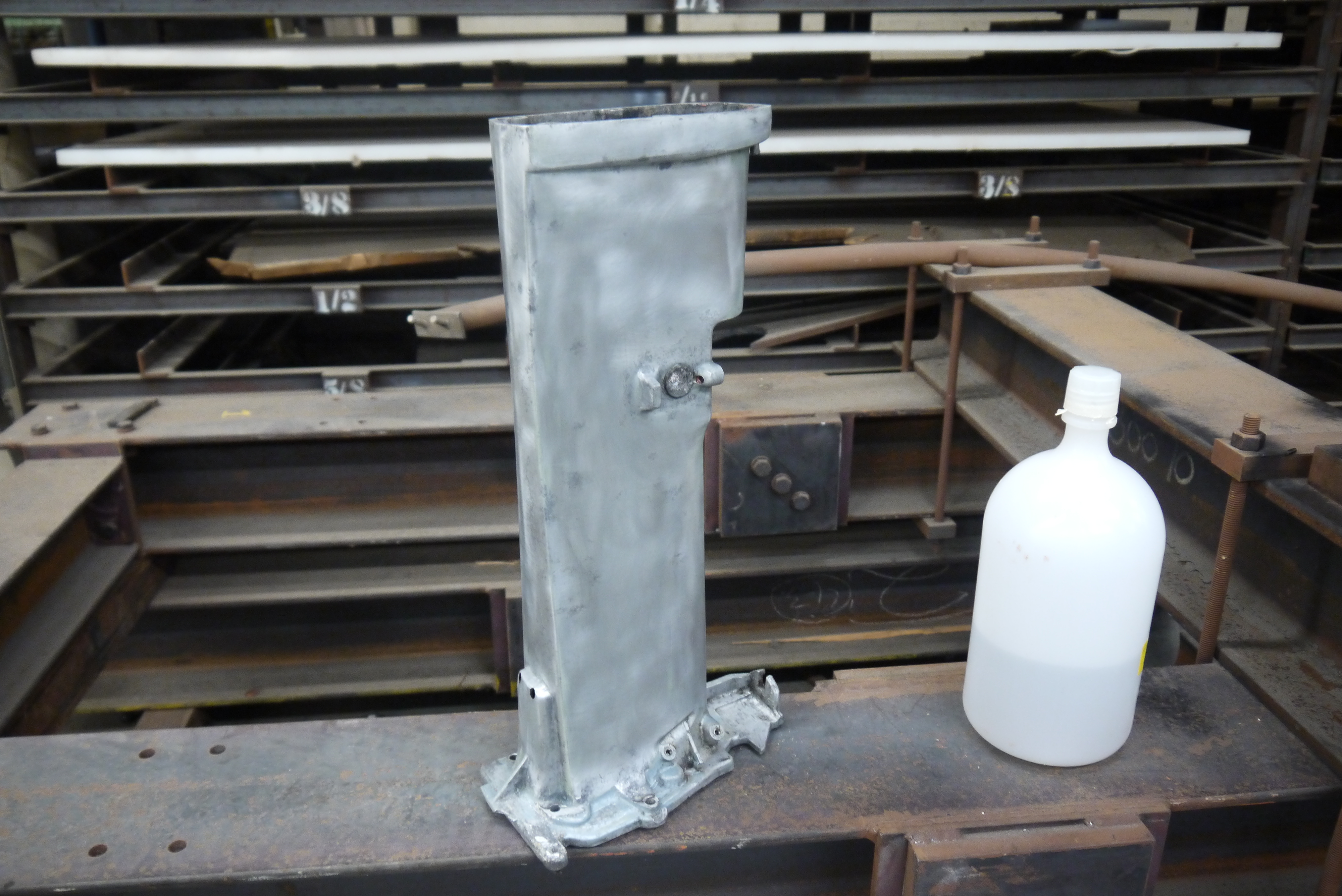
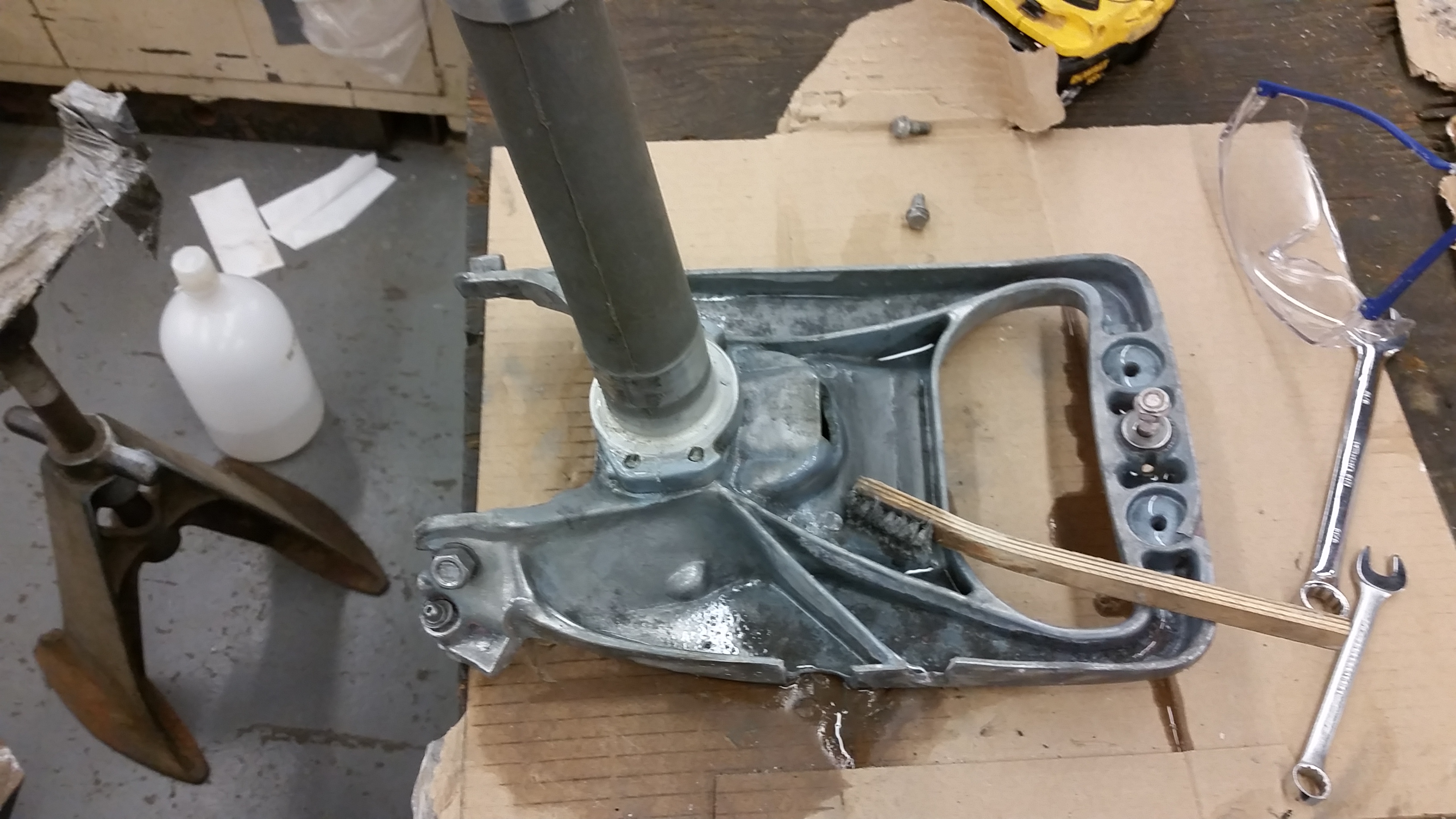
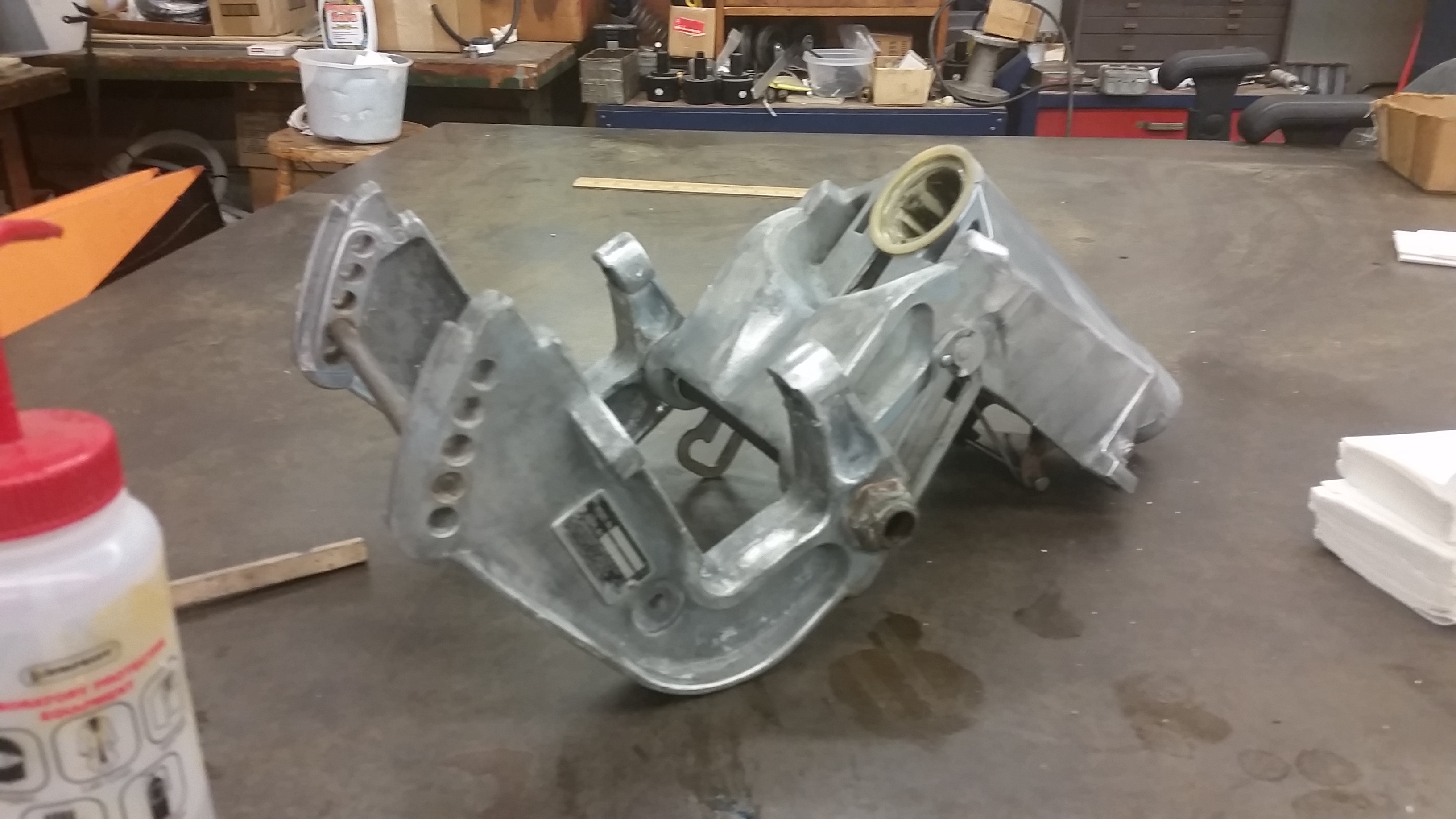
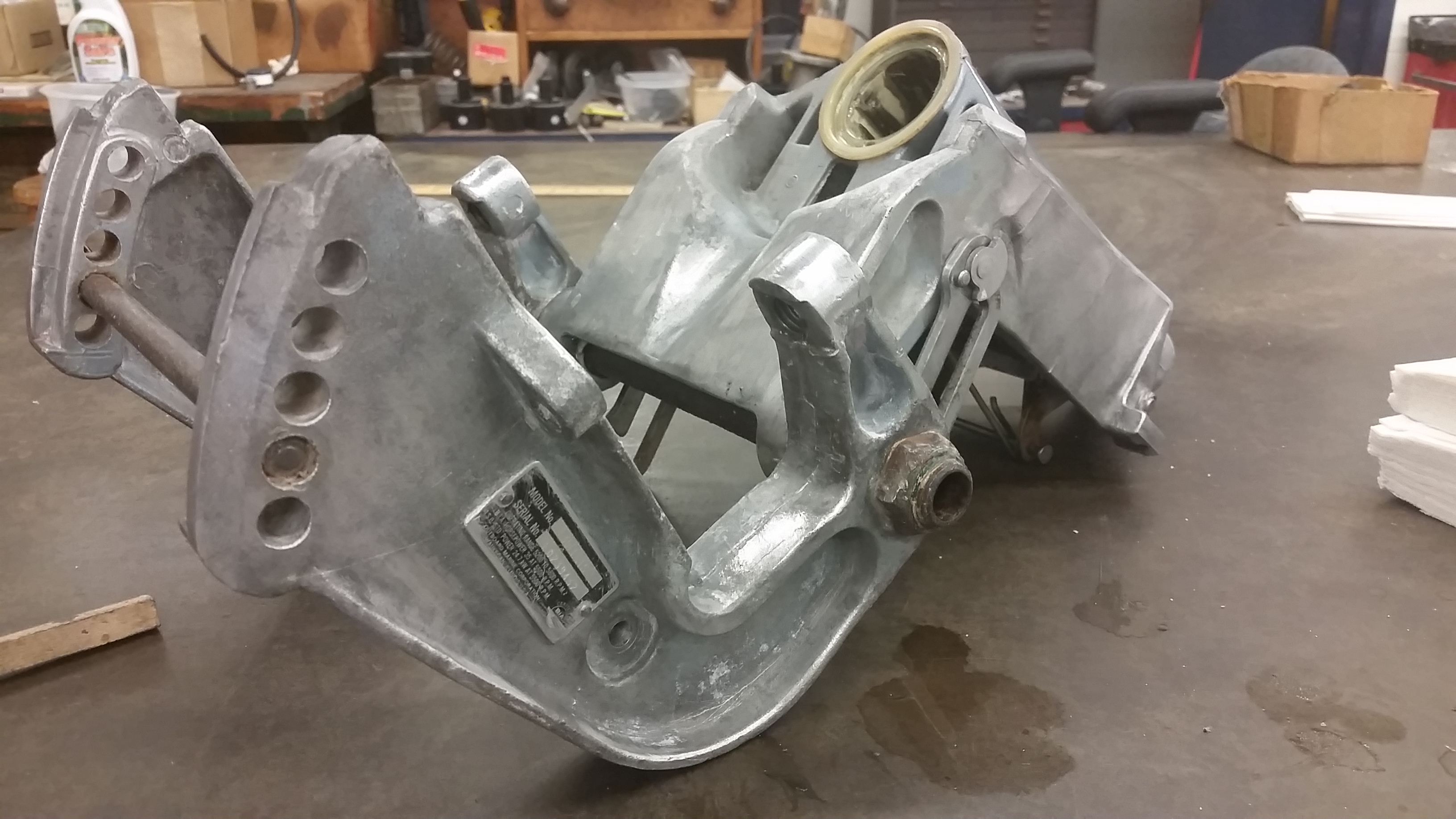
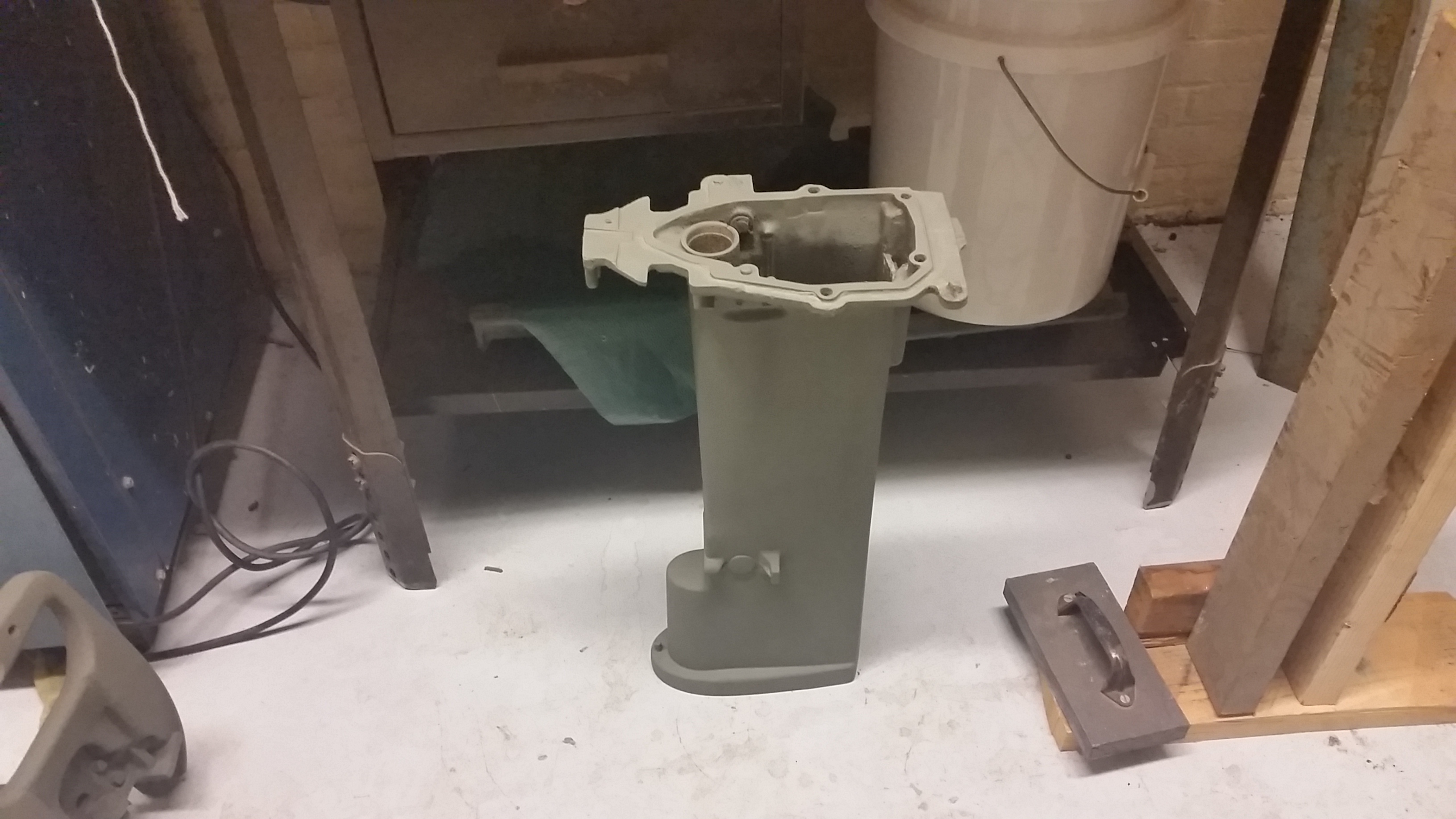
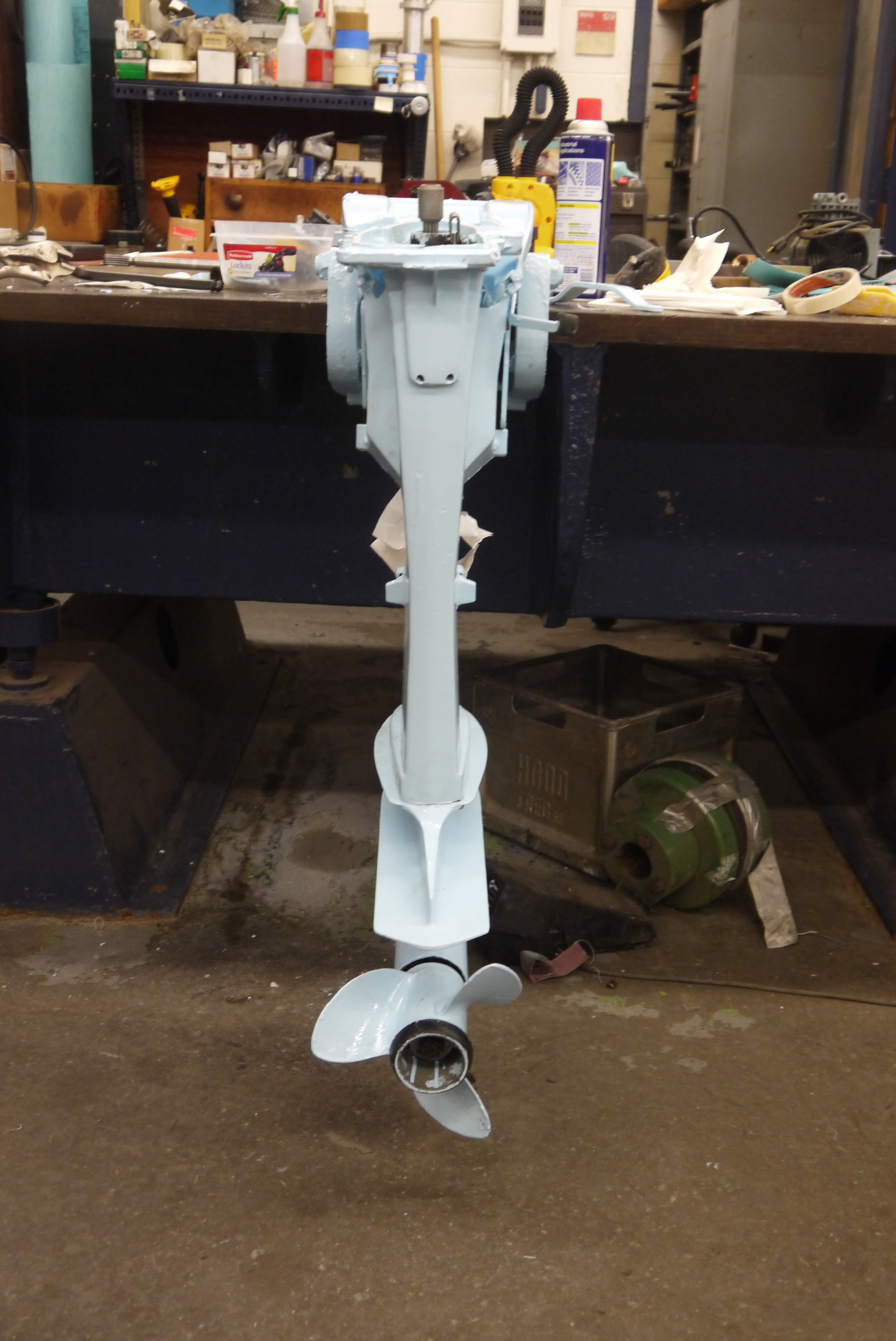
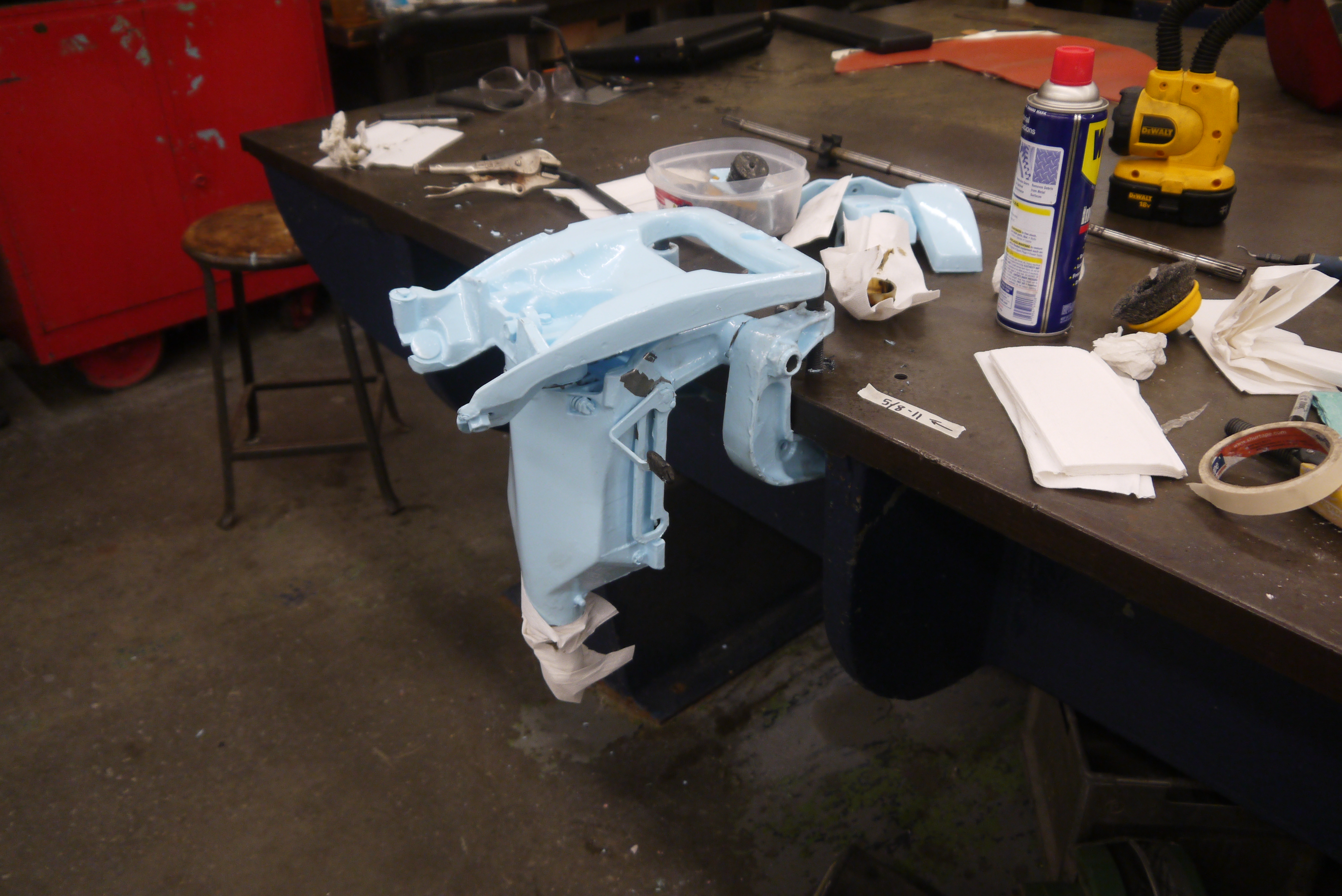
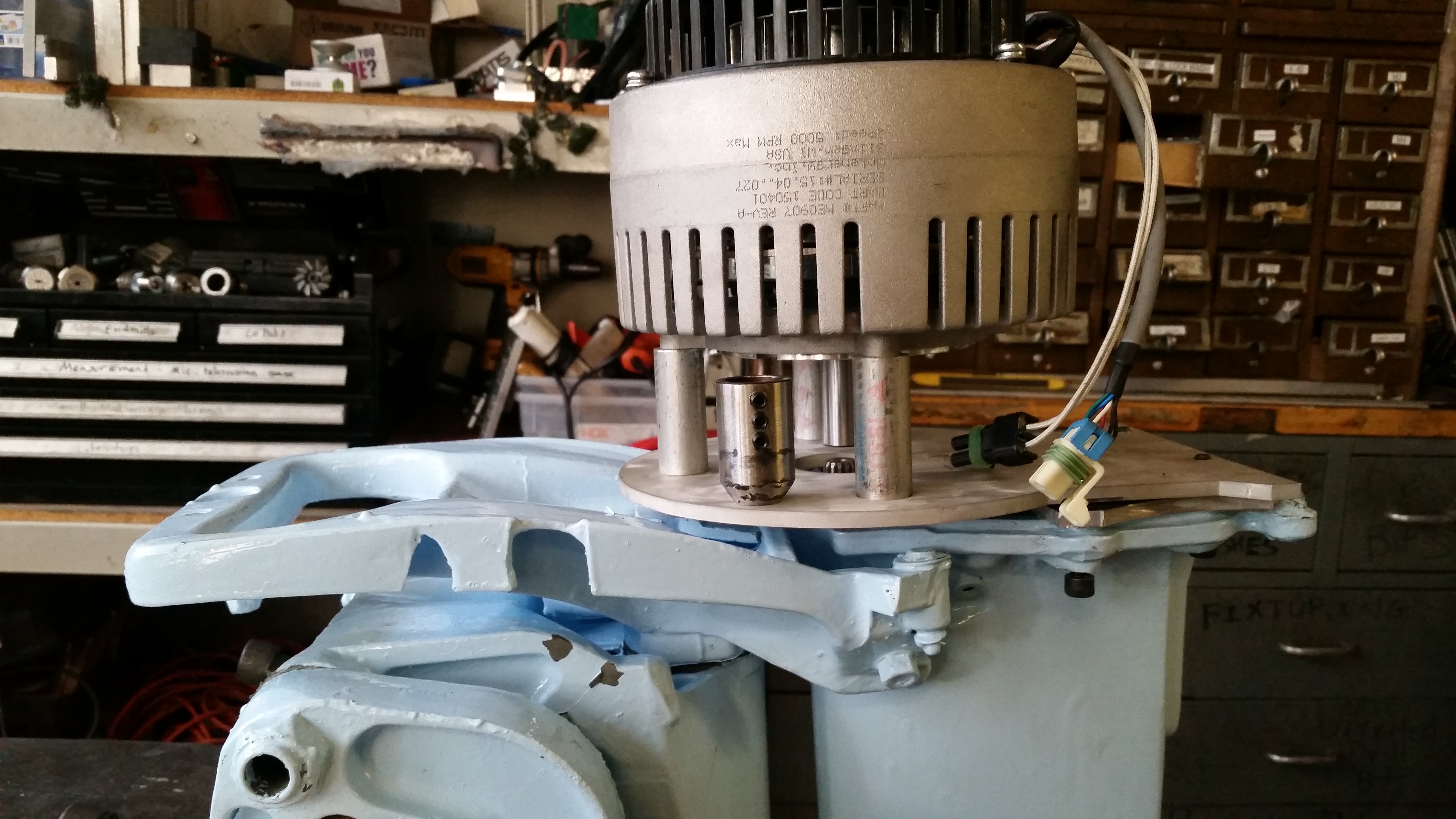
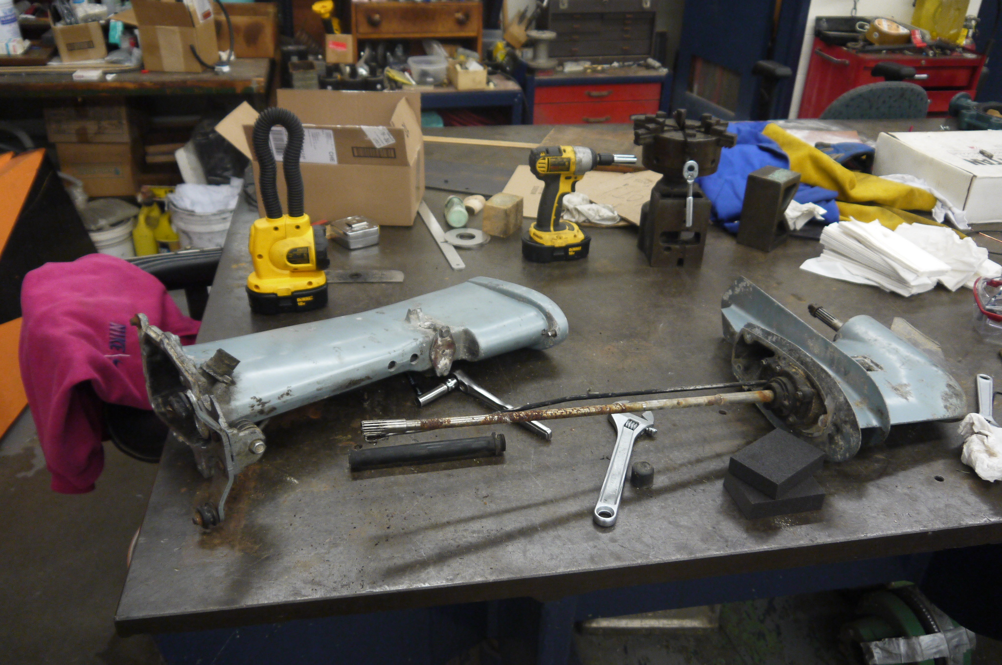 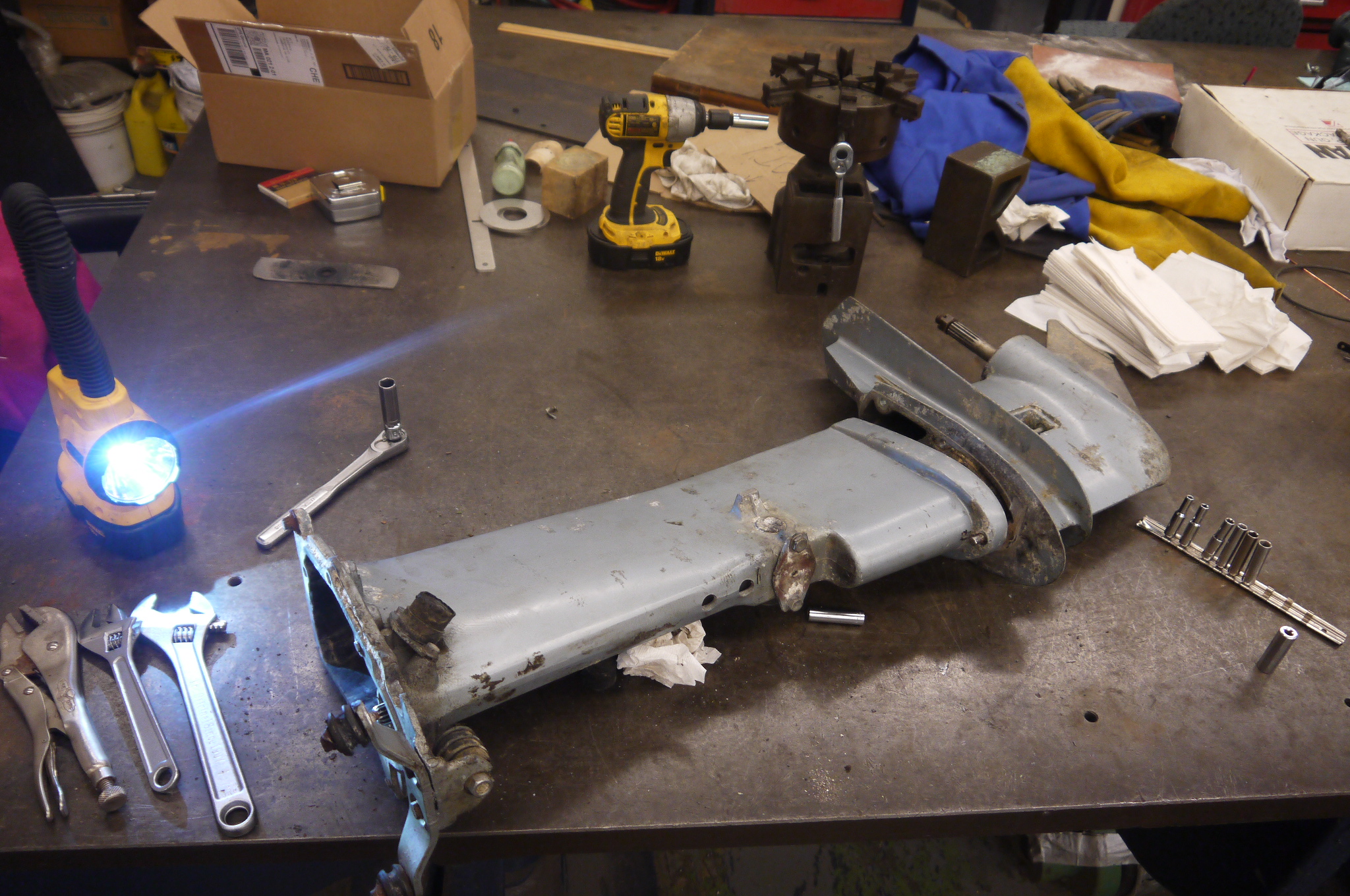 Here's
the outboard in its constituent parts, pulled from the
boat mount. Nominally this is the right-angle drive and
the long shaft housing, finally separated from the
outboard assembly. Here's
the outboard in its constituent parts, pulled from the
boat mount. Nominally this is the right-angle drive and
the long shaft housing, finally separated from the
outboard assembly. |
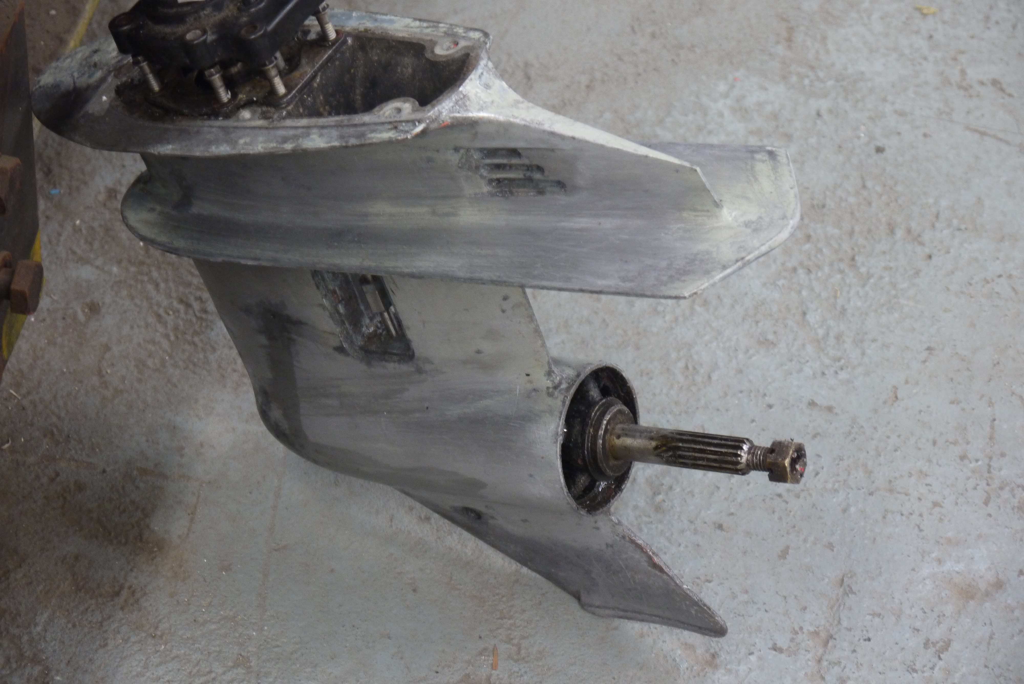
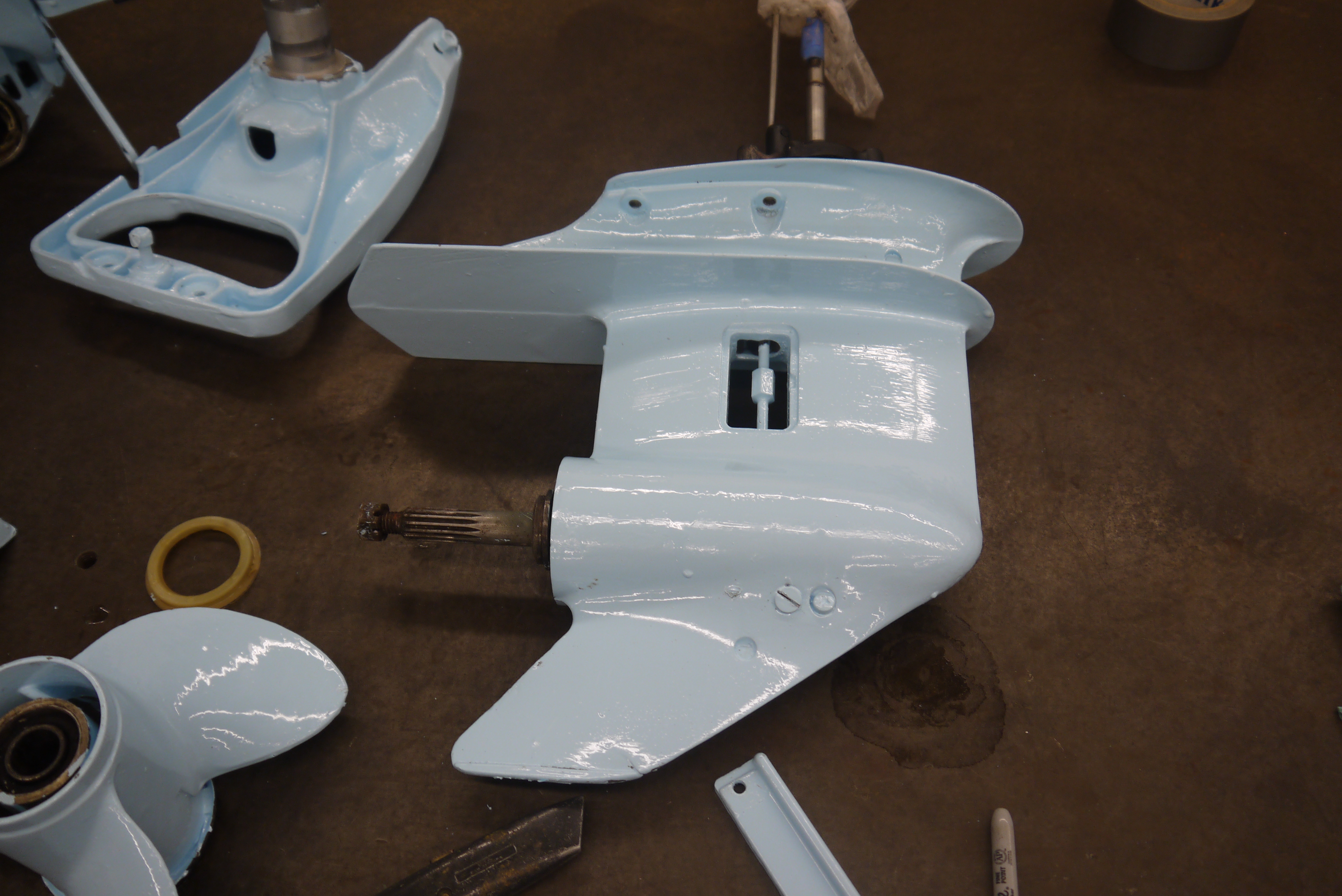
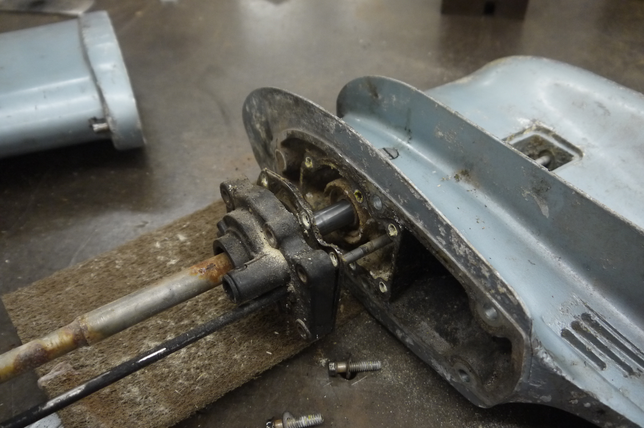 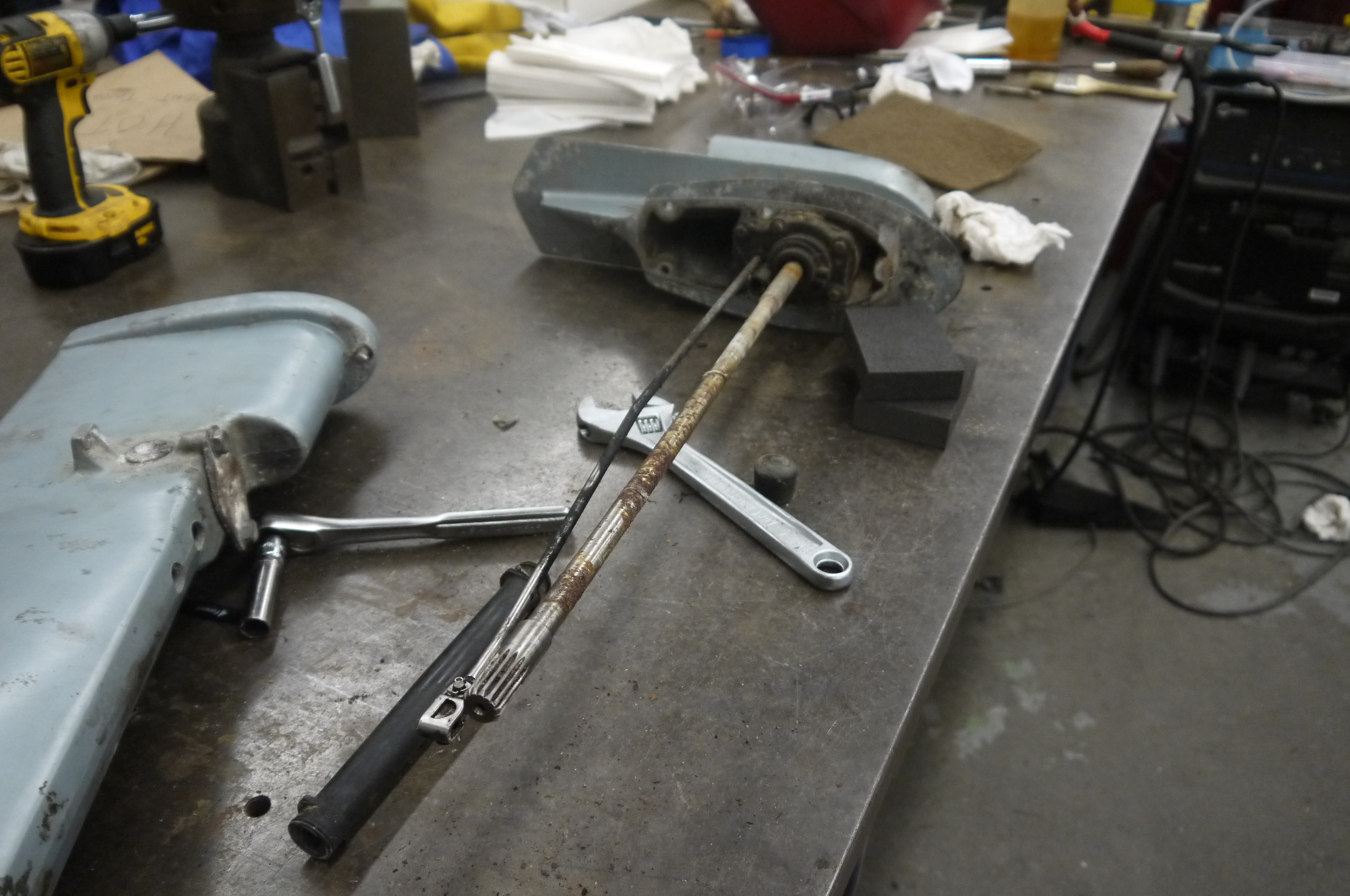 The
shaft had seen better days and was a might corroded.
Attempts were made at spot-cleaning the rust off, but
this was the deep-pitted kind :/ By eye the shaft also
didn't quite look straight
but that will be addressed later on. The
shaft had seen better days and was a might corroded.
Attempts were made at spot-cleaning the rust off, but
this was the deep-pitted kind :/ By eye the shaft also
didn't quite look straight
but that will be addressed later on. |
  The
right angle drive also contained some putrid smelling oil
which was drained out and flushed (temporairally) with
Jeep gear case oil. The proper evinrude gearbox oil was
not immediately available so jeep gear case oil was used
as it was easier to acquire (auto zone) and features a
convenient squirt nozzle. The
right angle drive also contained some putrid smelling oil
which was drained out and flushed (temporairally) with
Jeep gear case oil. The proper evinrude gearbox oil was
not immediately available so jeep gear case oil was used
as it was easier to acquire (auto zone) and features a
convenient squirt nozzle. |
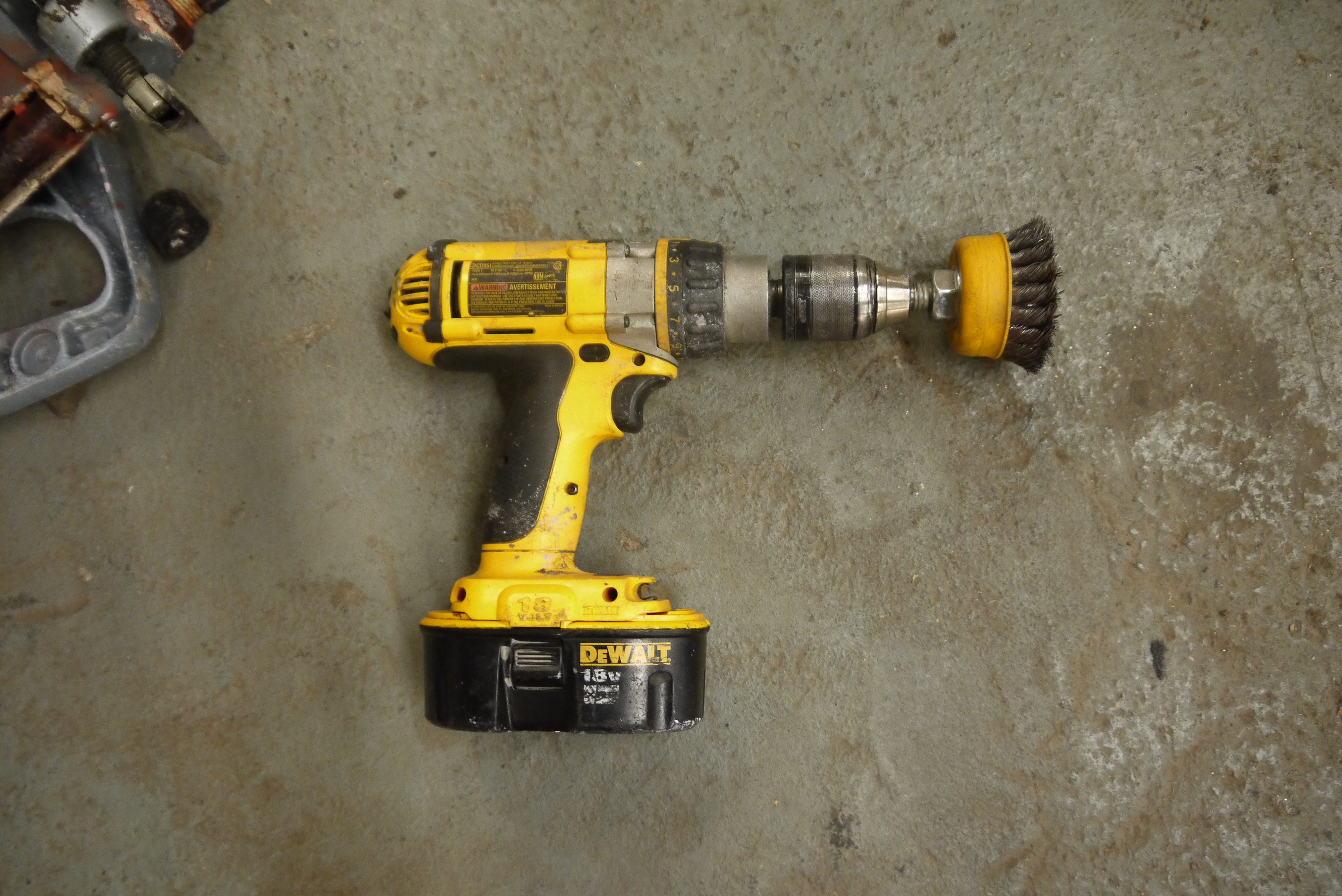
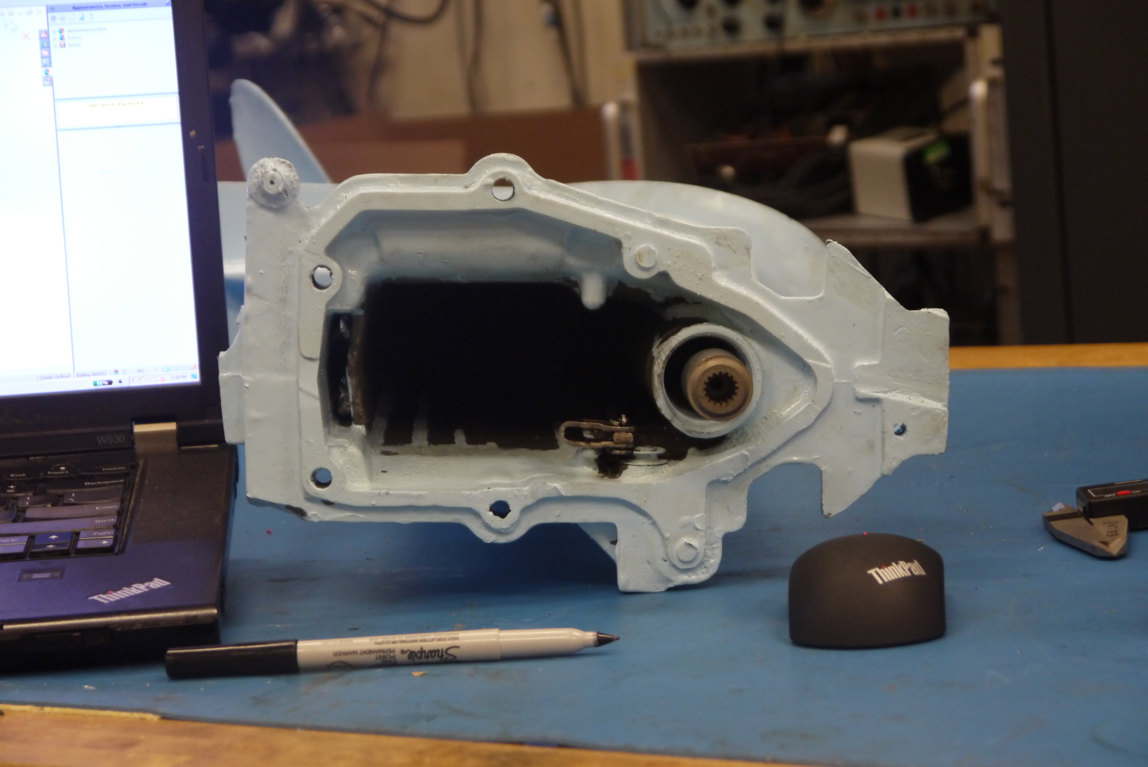
  So
next up was to possibly replace the bearing seals and or
inspect the bearings. I made a tool to yank on the
internal threads against the case. This did not work at
all, everything in there was seized to the case, as in,
impact driver going full tilt was not moving anything.
So for the time being the bearings and seals are 'decent
enough'. So
next up was to possibly replace the bearing seals and or
inspect the bearings. I made a tool to yank on the
internal threads against the case. This did not work at
all, everything in there was seized to the case, as in,
impact driver going full tilt was not moving anything.
So for the time being the bearings and seals are 'decent
enough'. |
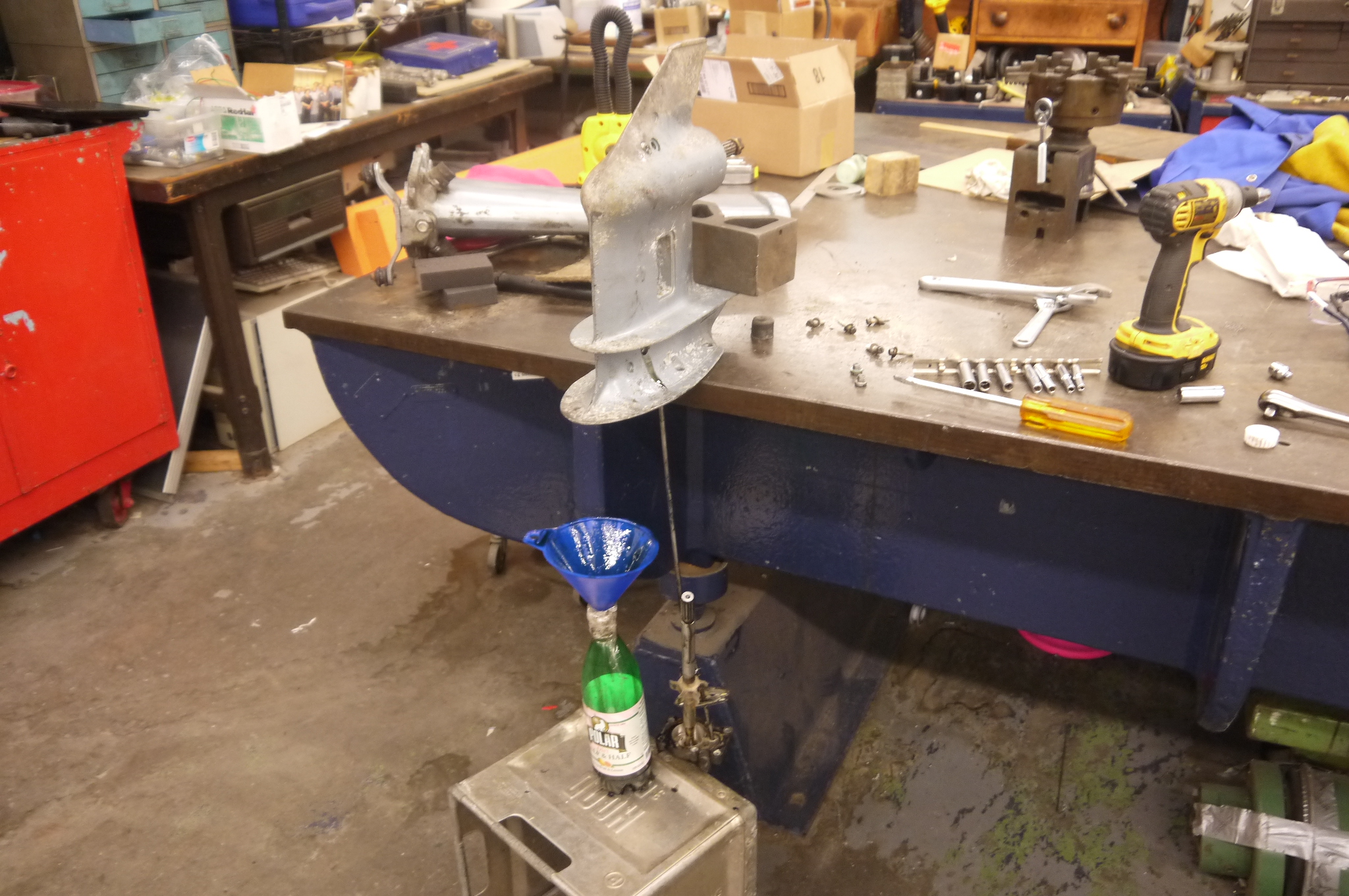
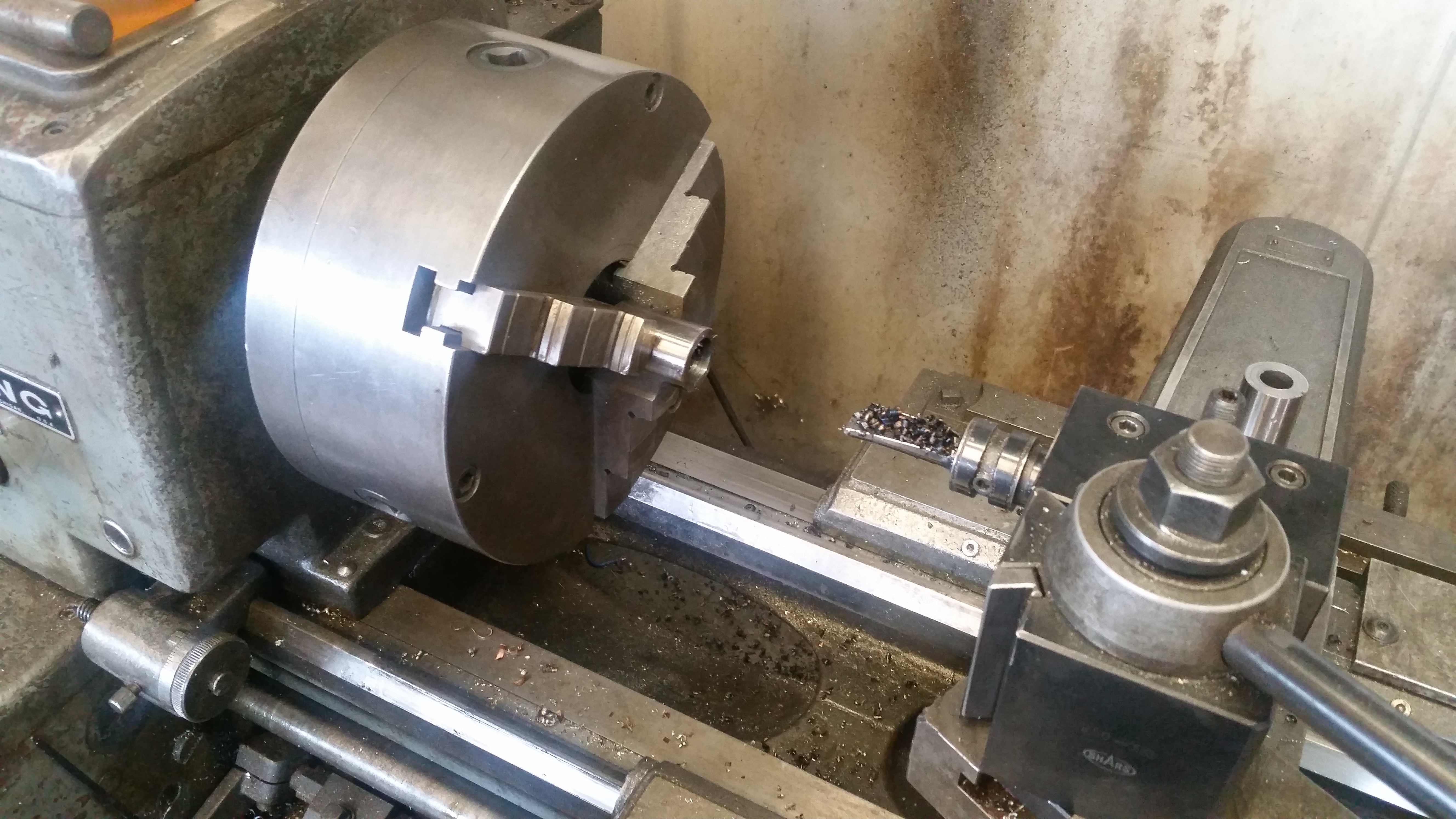
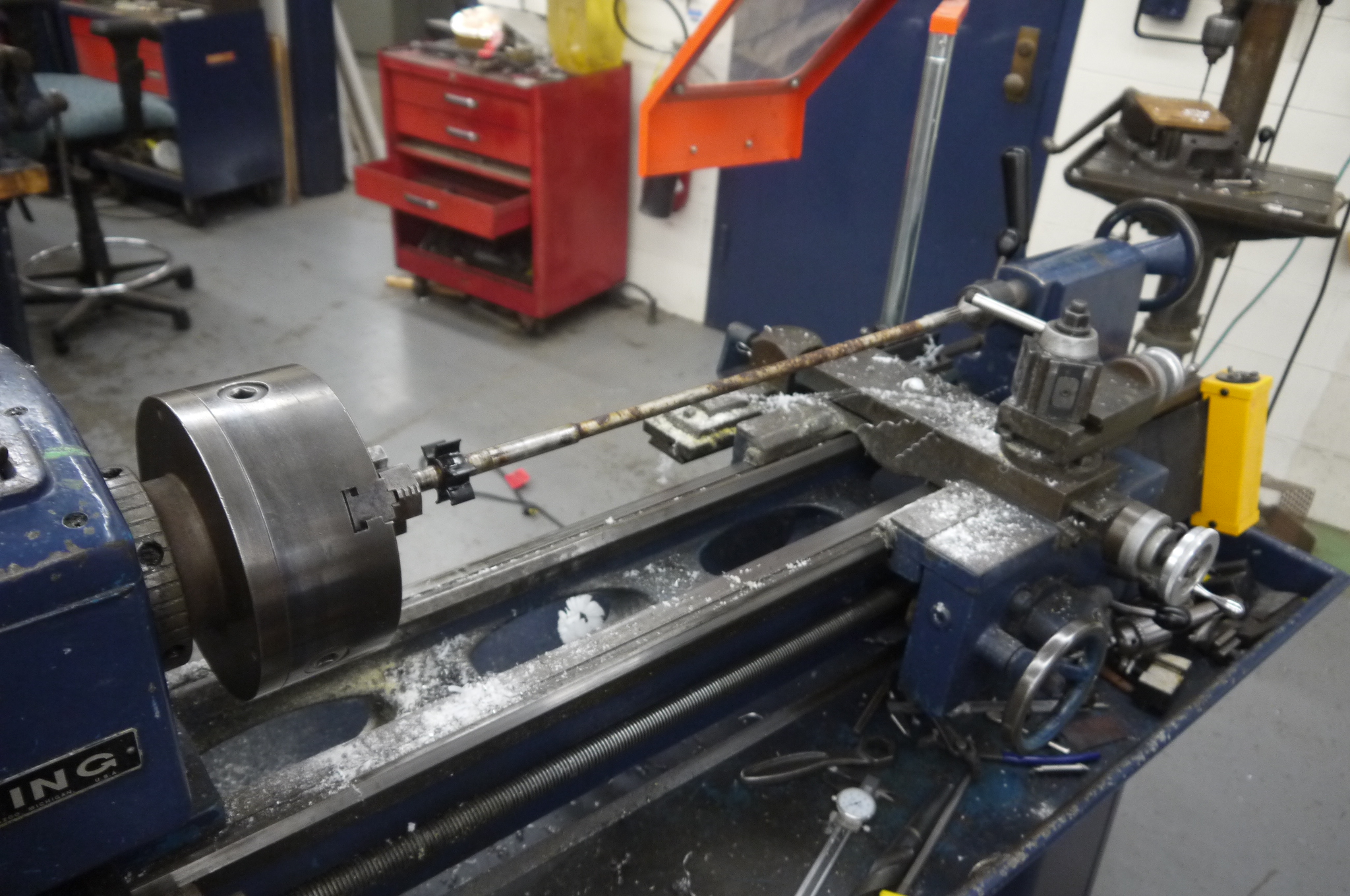  Ok
lets take a look at the splined drive shaft. To do this
i mounted the shaft in a 3-jaw chuck in an older
clausing lathe, with the live center as a reference. Yep
it was quite sad and rusty, shown in the video
below. Ok
lets take a look at the splined drive shaft. To do this
i mounted the shaft in a 3-jaw chuck in an older
clausing lathe, with the live center as a reference. Yep
it was quite sad and rusty, shown in the video
below. |
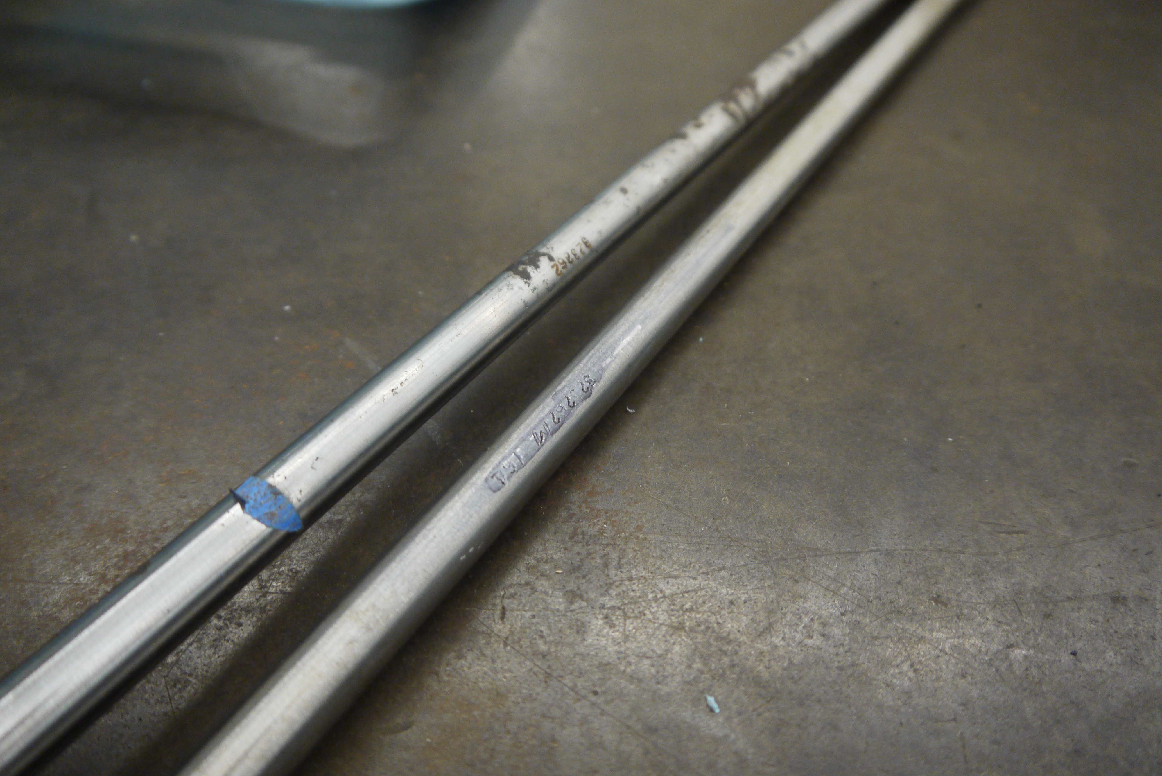  Its
amazing that a brand new shaft for a ~30+ old year
outboard is available with 2 day delivery. The new shaft
bore the same model number engraving and appeared to be
form and function identical. Quite an excellent finish
for a 30$ ebay part. Its
amazing that a brand new shaft for a ~30+ old year
outboard is available with 2 day delivery. The new shaft
bore the same model number engraving and appeared to be
form and function identical. Quite an excellent finish
for a 30$ ebay part. |
| Outboard Shaft wobble | |
| As its fairly visible in the video, the shaft that mates the lower end to the engine was quite sad. The live center on the lathe is col-linear with the center axis of the chuck, so any deviations indicate that the device in the chuck is not 'centered'. What i don't quite understand is how this got so bad. Either way this wasn't going to do for any reasonable amount of operation. I managed to find a vendor selling replacement shafts (ebay) and it was impressively better with the new shaft mounted. |


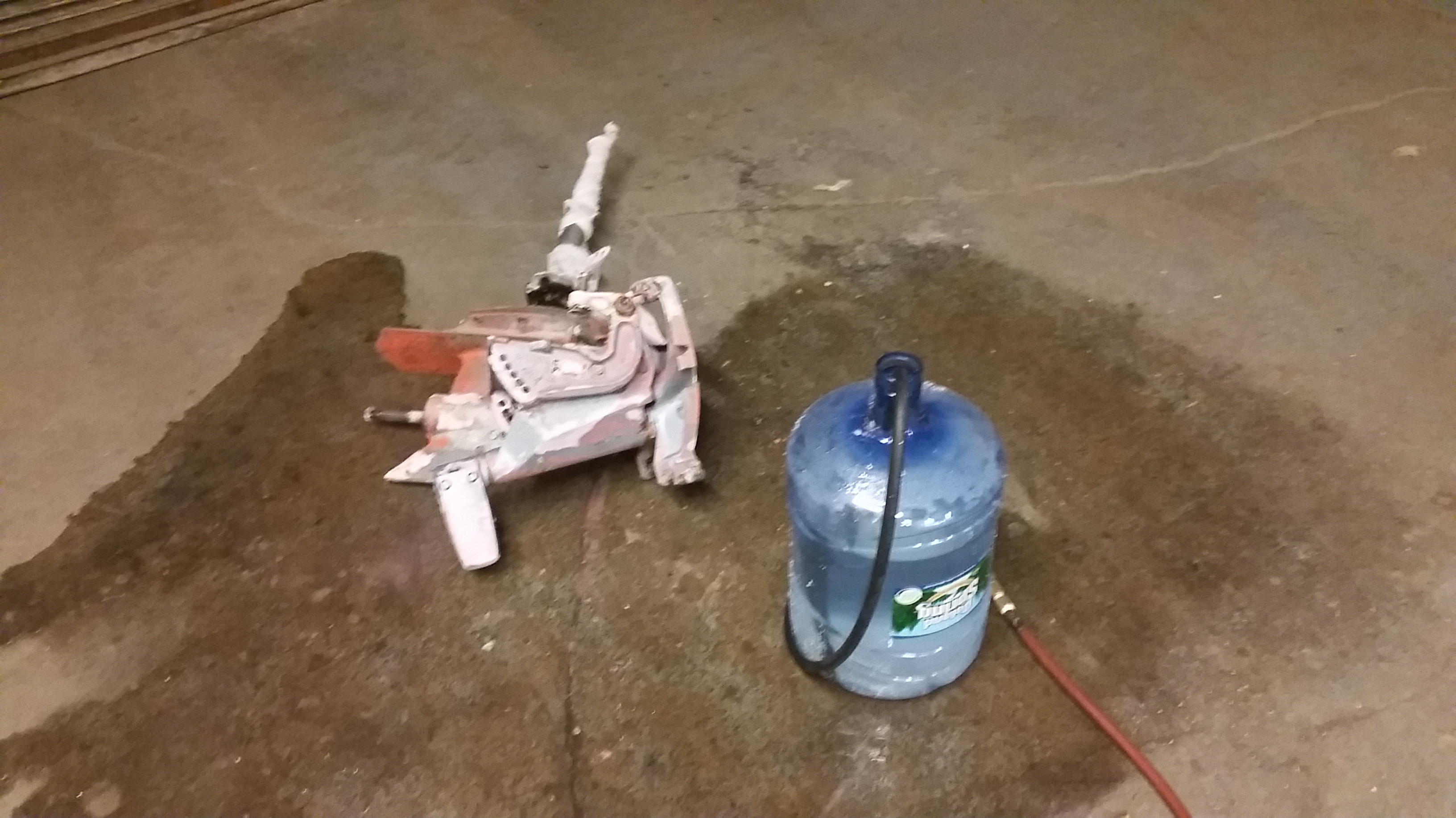


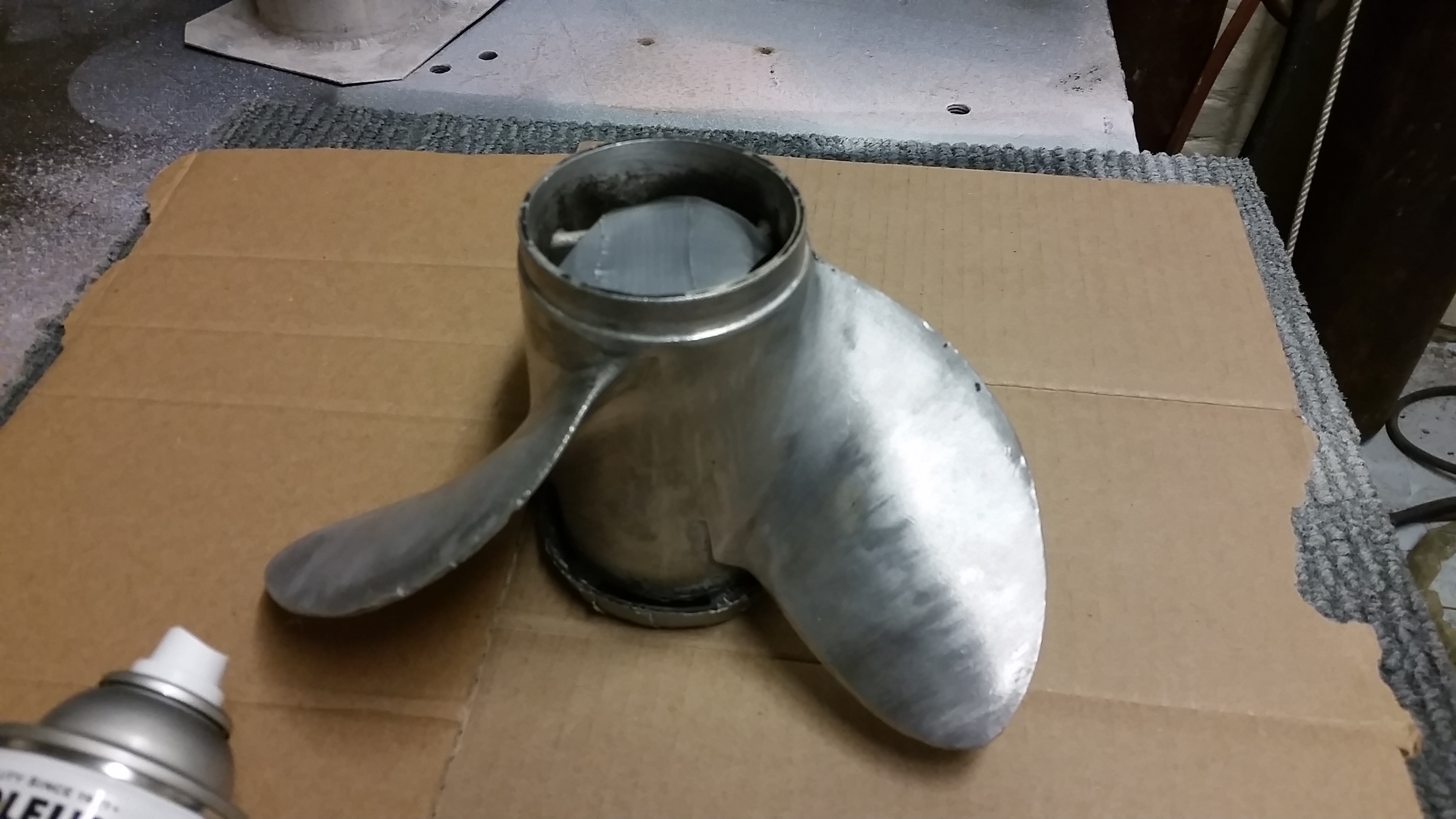
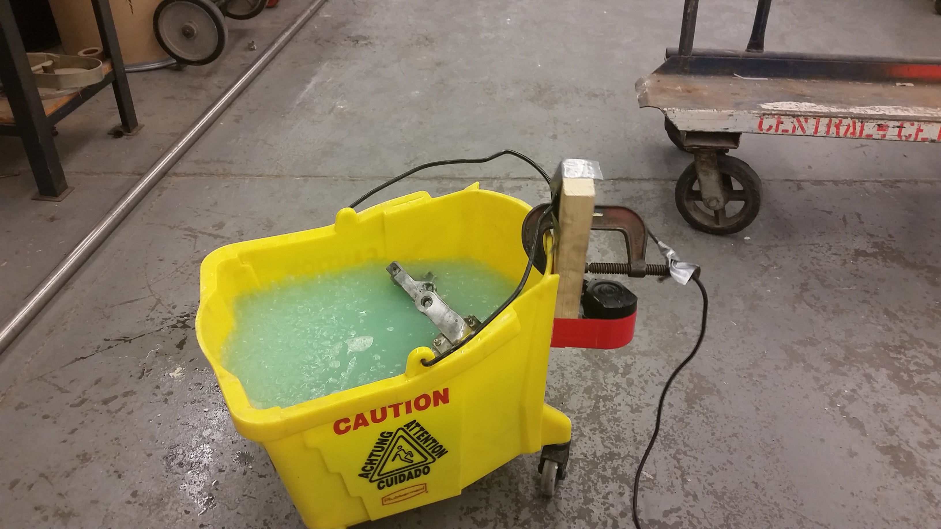
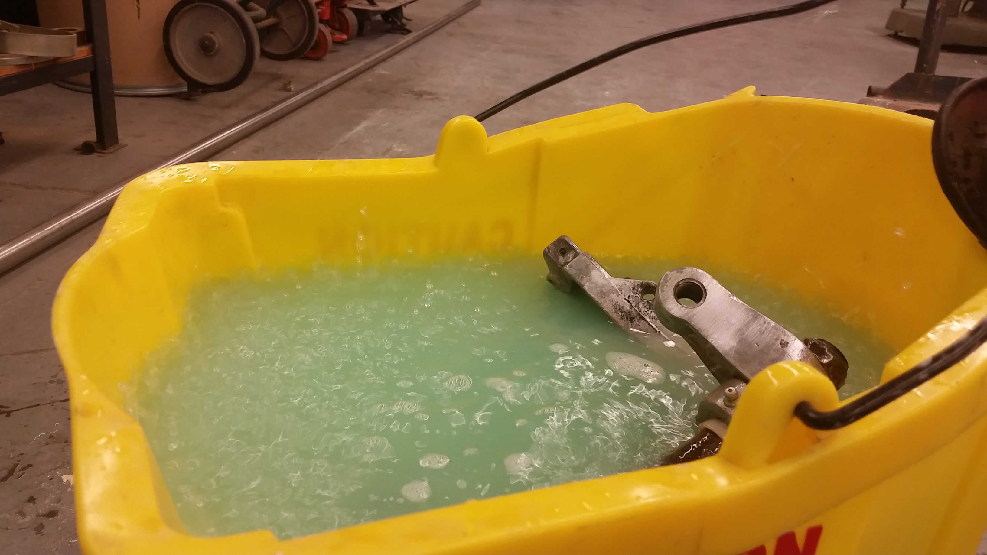
| Vibratory washing | |
| This was a bit of a silly exercise in cleaning all of the inset parts of the aluminum casting. I used a small 24v dc motor and adding an offset mass to the shaft to make a realtivley low frequency oscillator. This worked surprisingly well, as the solvents in the janitor-bucket had an opportunity to jostled allowing more solvent in deep pocketed areas. Surprisingly given the bucket was on wheels, it seemed to still do quite well at washing and dissolving off paint and primer that was left on the casting. | |
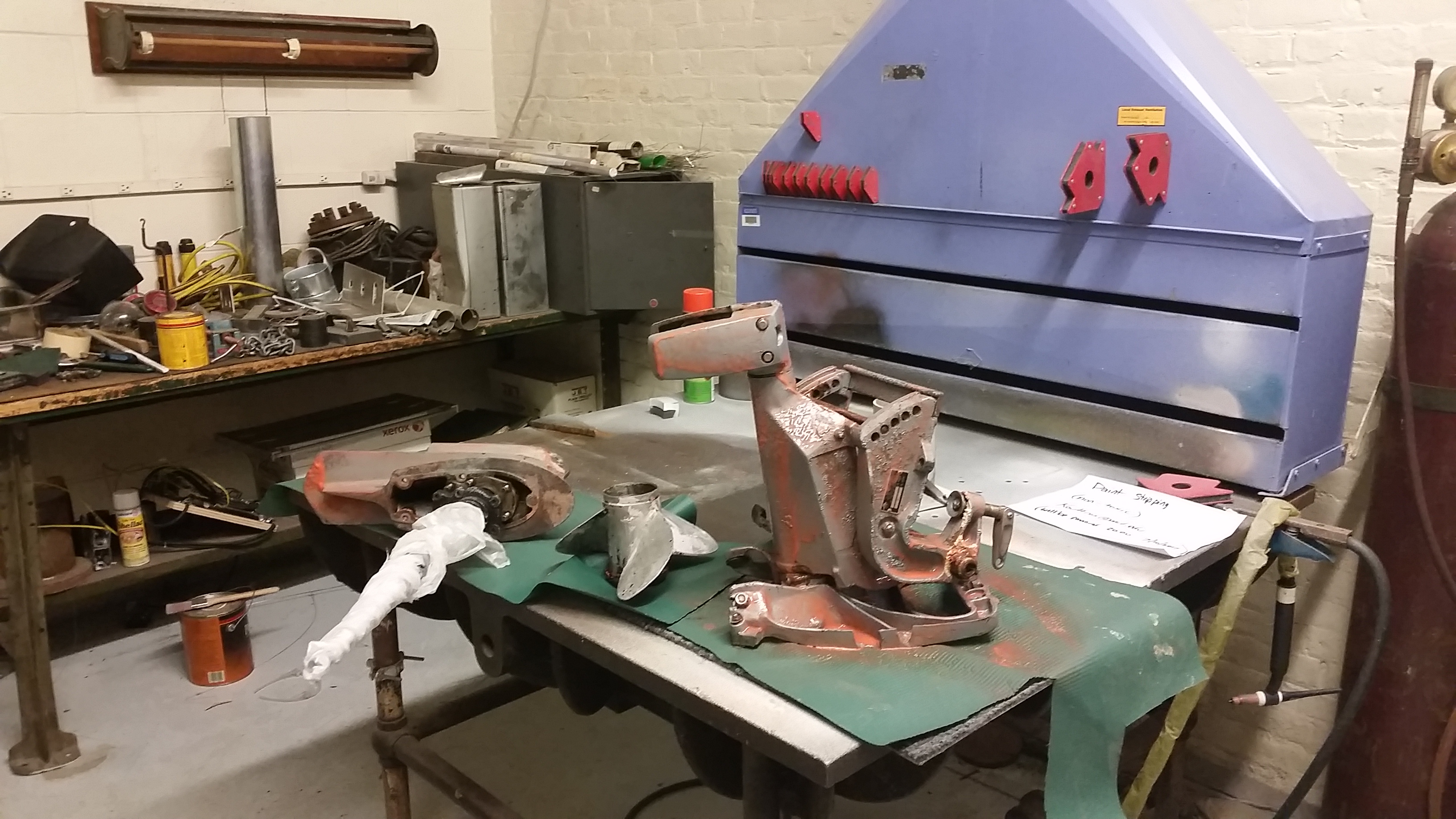
| Painting The outboard Part 1:
Respirators and cassette tape |
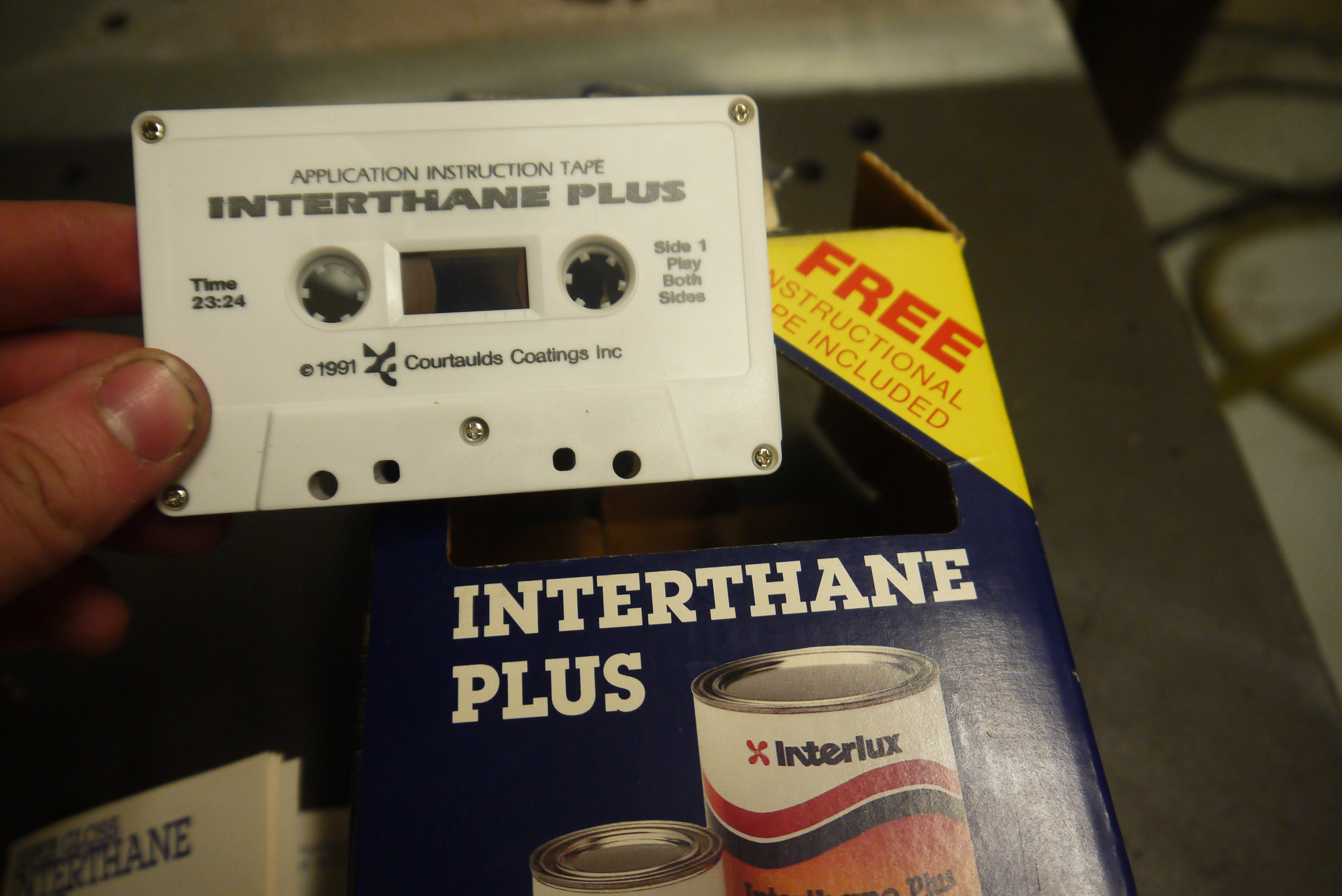 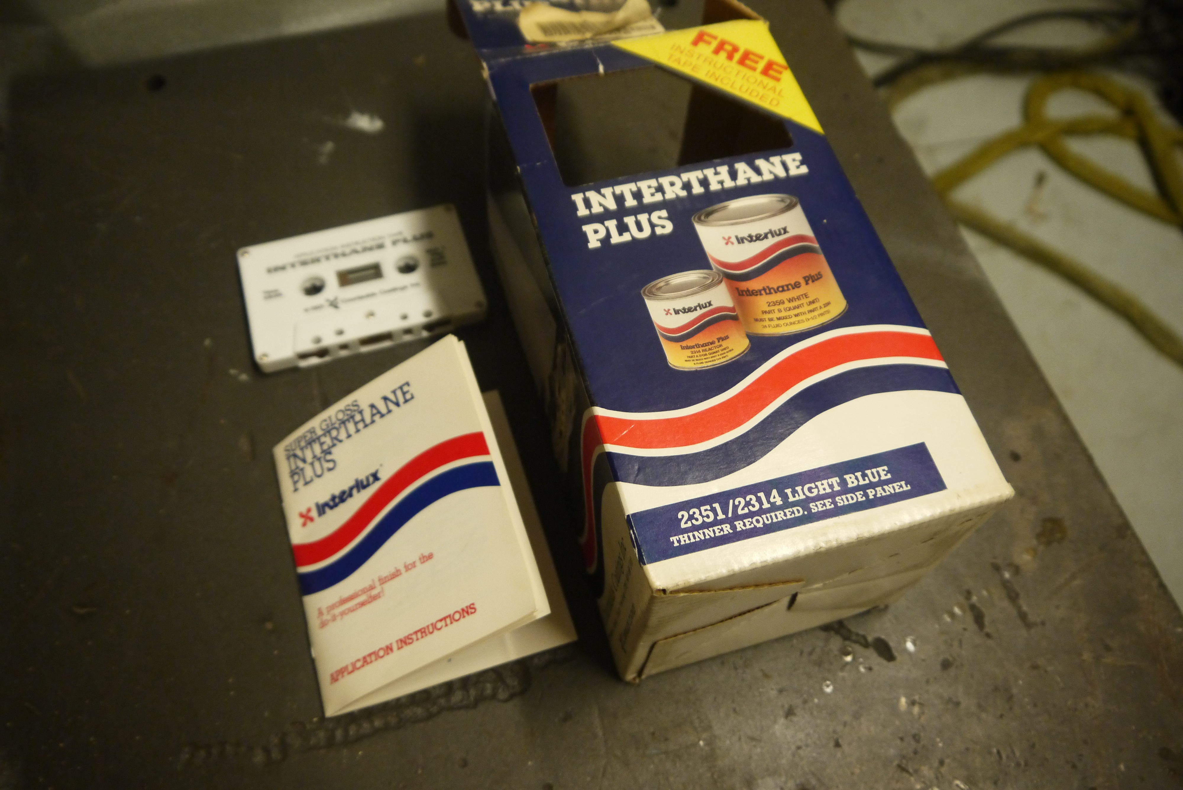 I wanted to get the
outboard up and assembled to get to work on the
electronics and mechanicals. I didn't want to wait for
online paint retailers so I purchased some epoxy based
marine paint to cover the primered parts. I visited CG
Edwards and grabbed an old, light blue paint kit. I
hadn't known that they no longer actually carry paint,
but are more of a shipping intermediary, so there were
some quite limited options. Initially, I didn't quite
realize how old this marine epoxy paint was. The
cassette was labeled 1993, yes the paint included
an information cassette tape. Literally a cassette
tape. I wanted to get the
outboard up and assembled to get to work on the
electronics and mechanicals. I didn't want to wait for
online paint retailers so I purchased some epoxy based
marine paint to cover the primered parts. I visited CG
Edwards and grabbed an old, light blue paint kit. I
hadn't known that they no longer actually carry paint,
but are more of a shipping intermediary, so there were
some quite limited options. Initially, I didn't quite
realize how old this marine epoxy paint was. The
cassette was labeled 1993, yes the paint included
an information cassette tape. Literally a cassette
tape. |
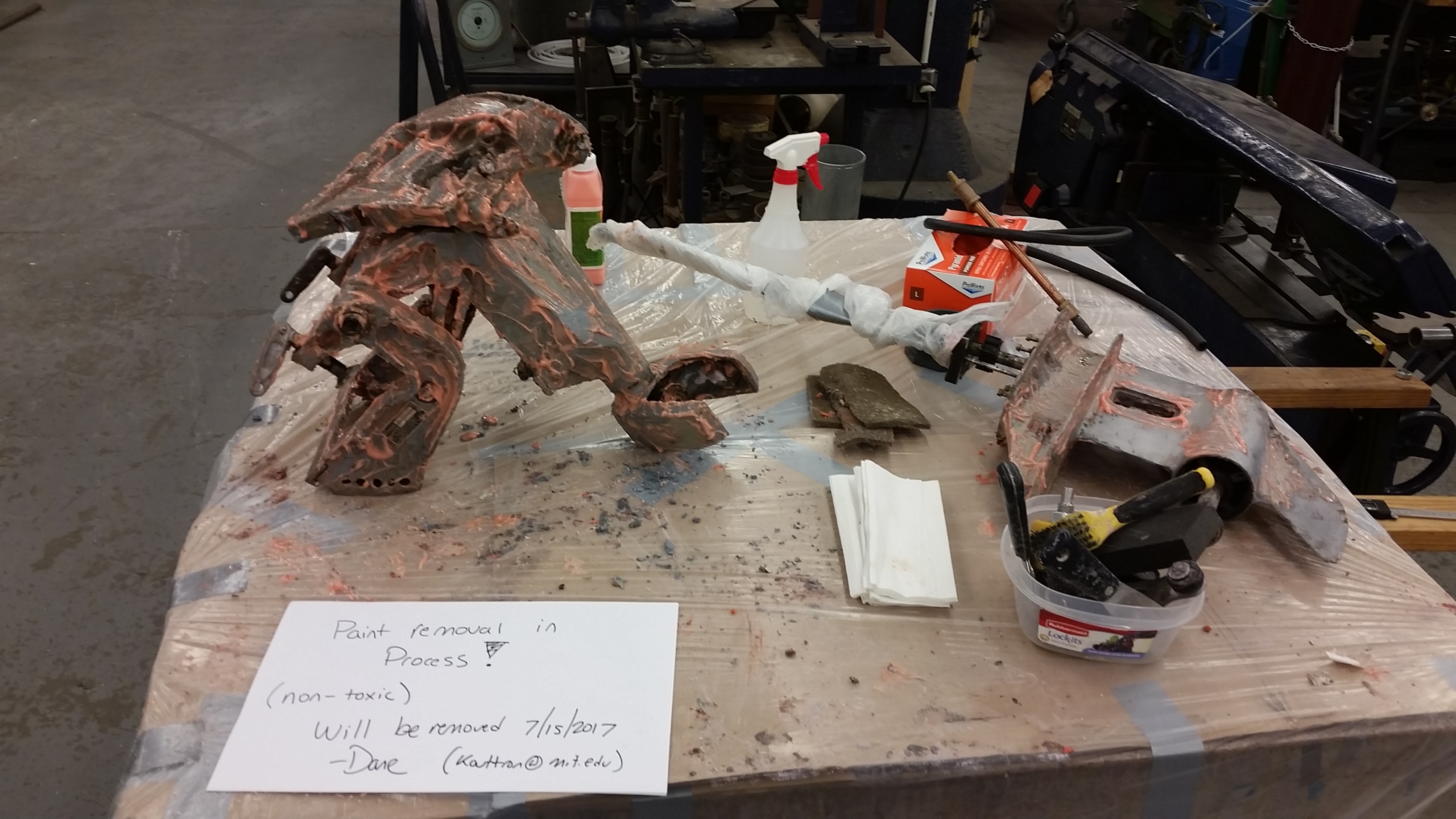
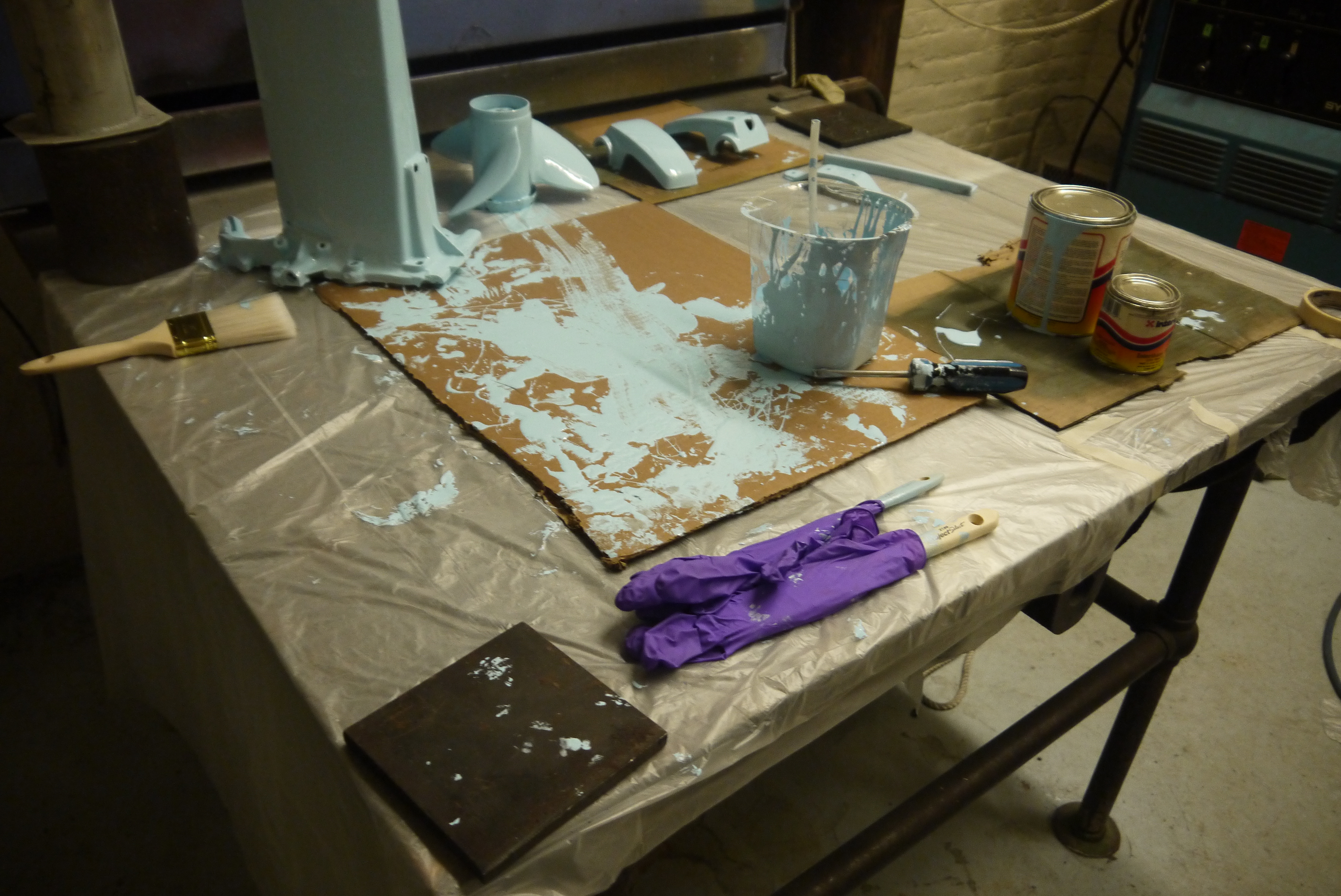
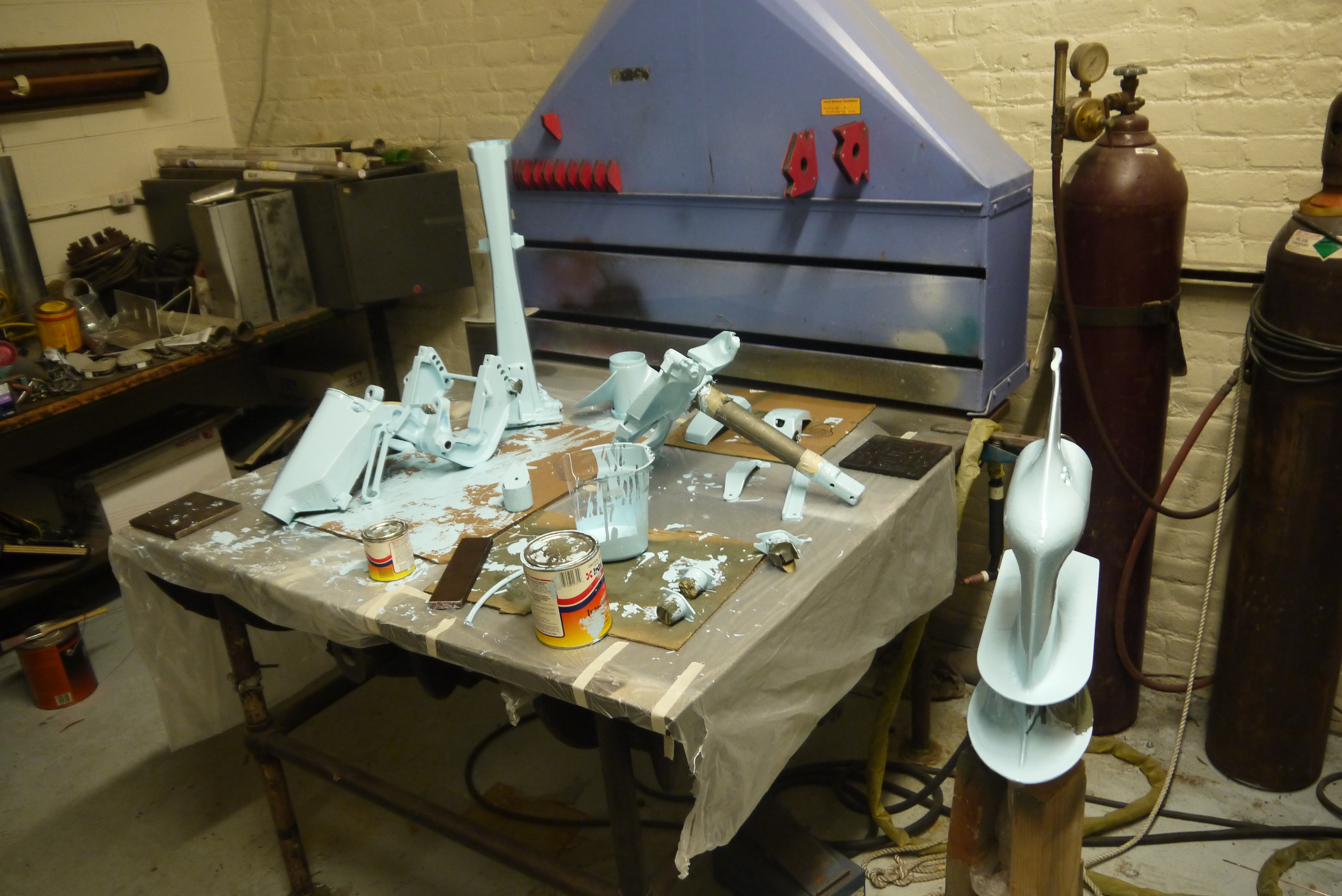
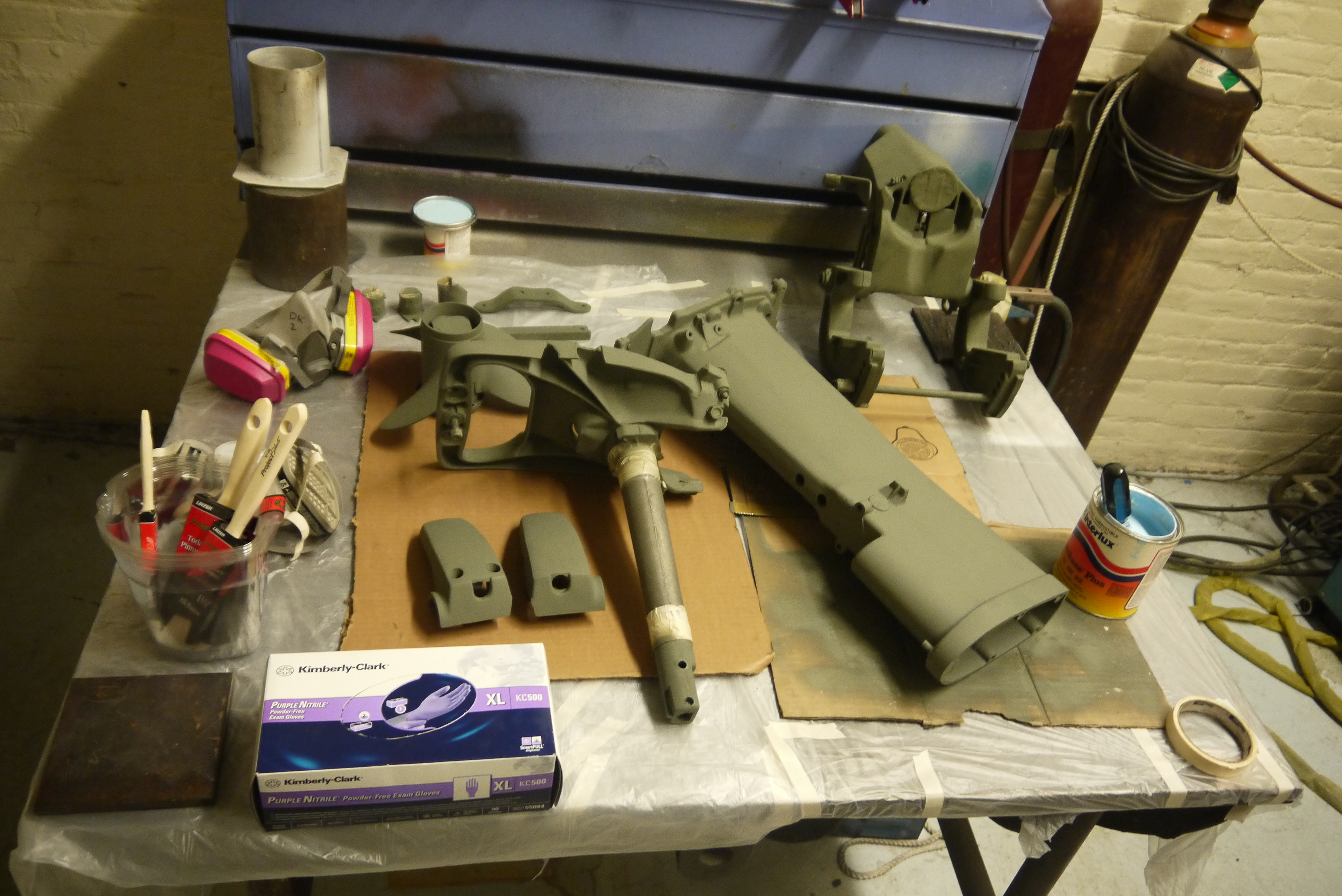 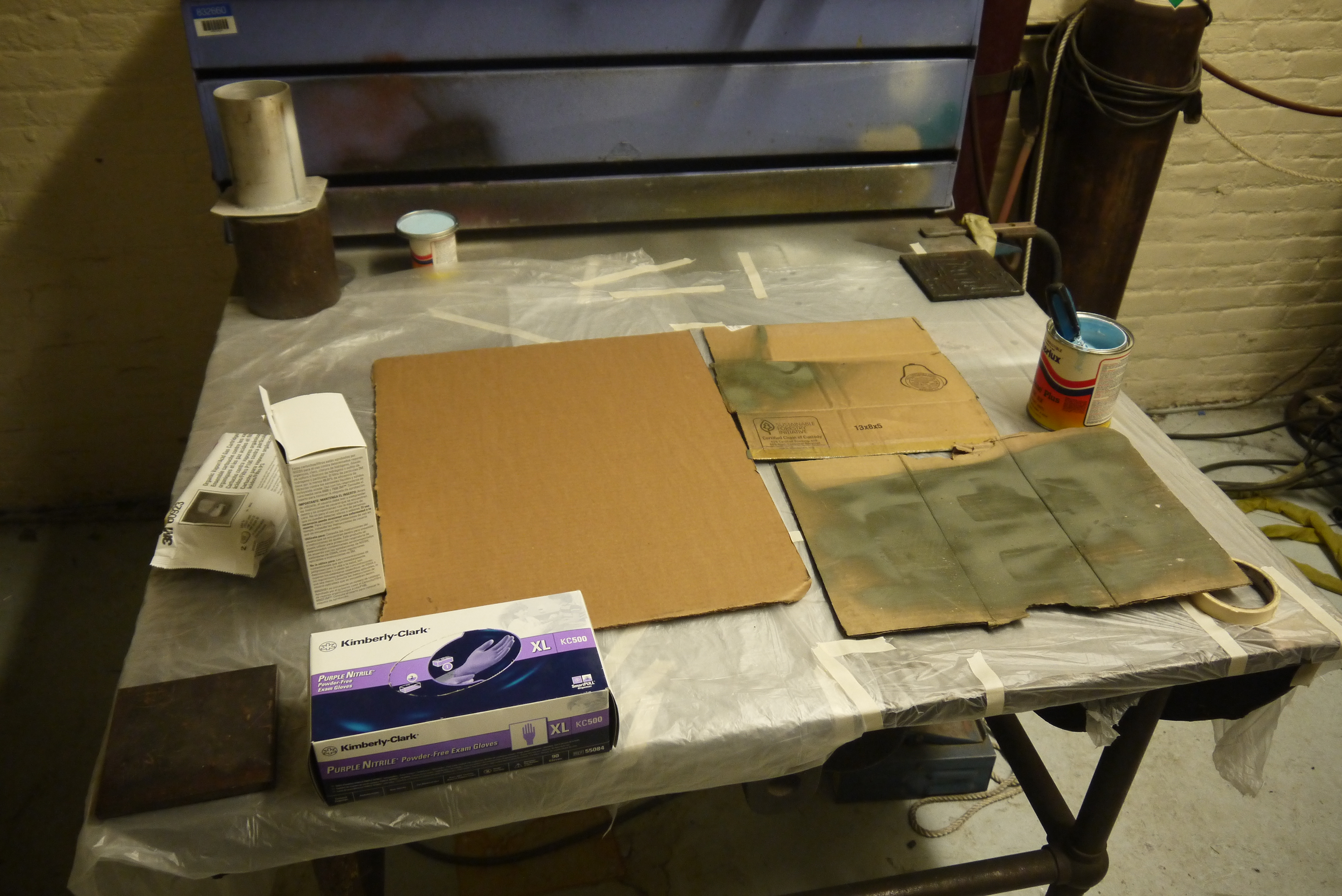 PREP
TIME! PREP
TIME!This is a ventilated welding / paint room, where the rear part of the room has a negative pressure to take care of the fumes. Plastic garbage bags are used to keep the table clean, and make cleanup easy. |
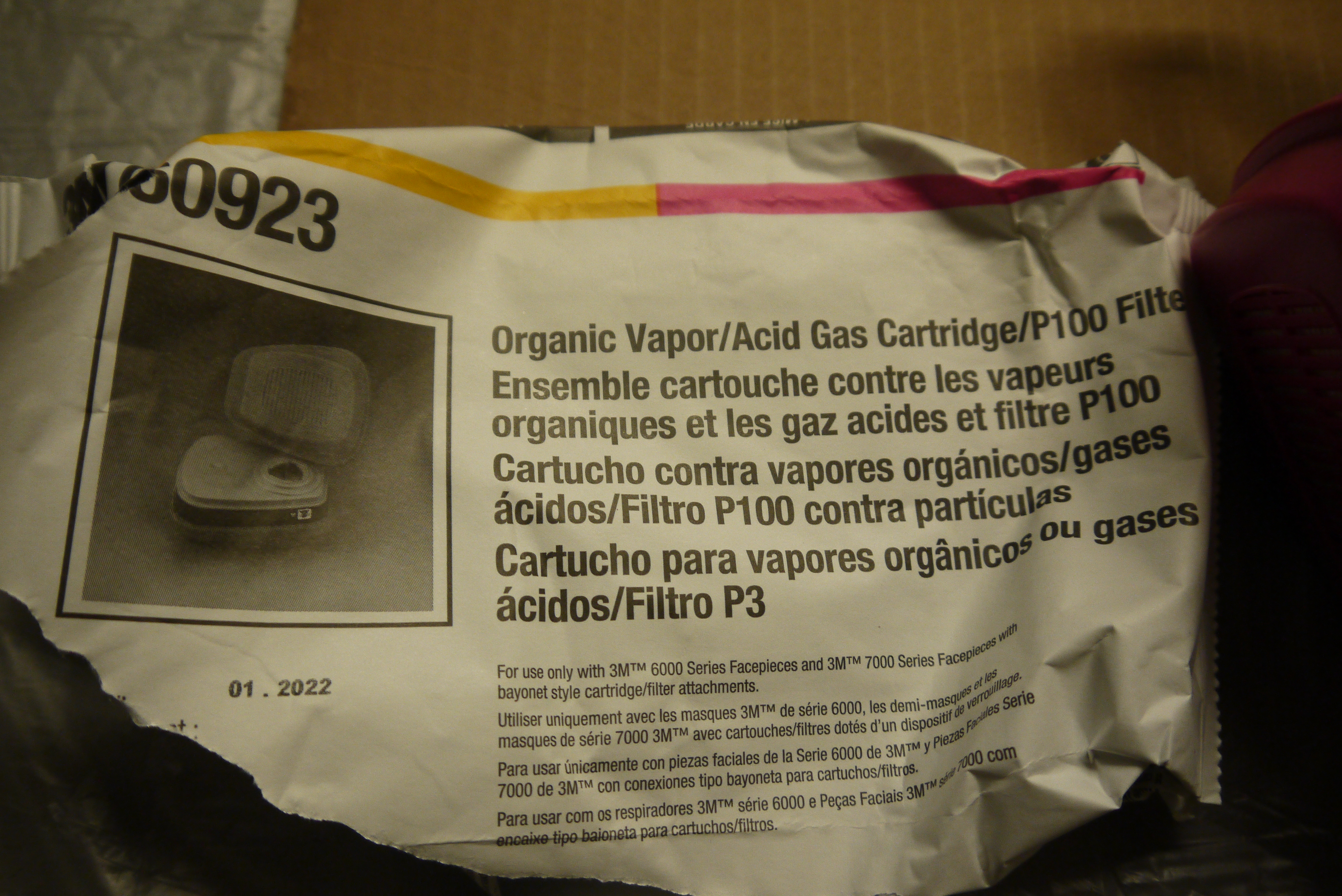 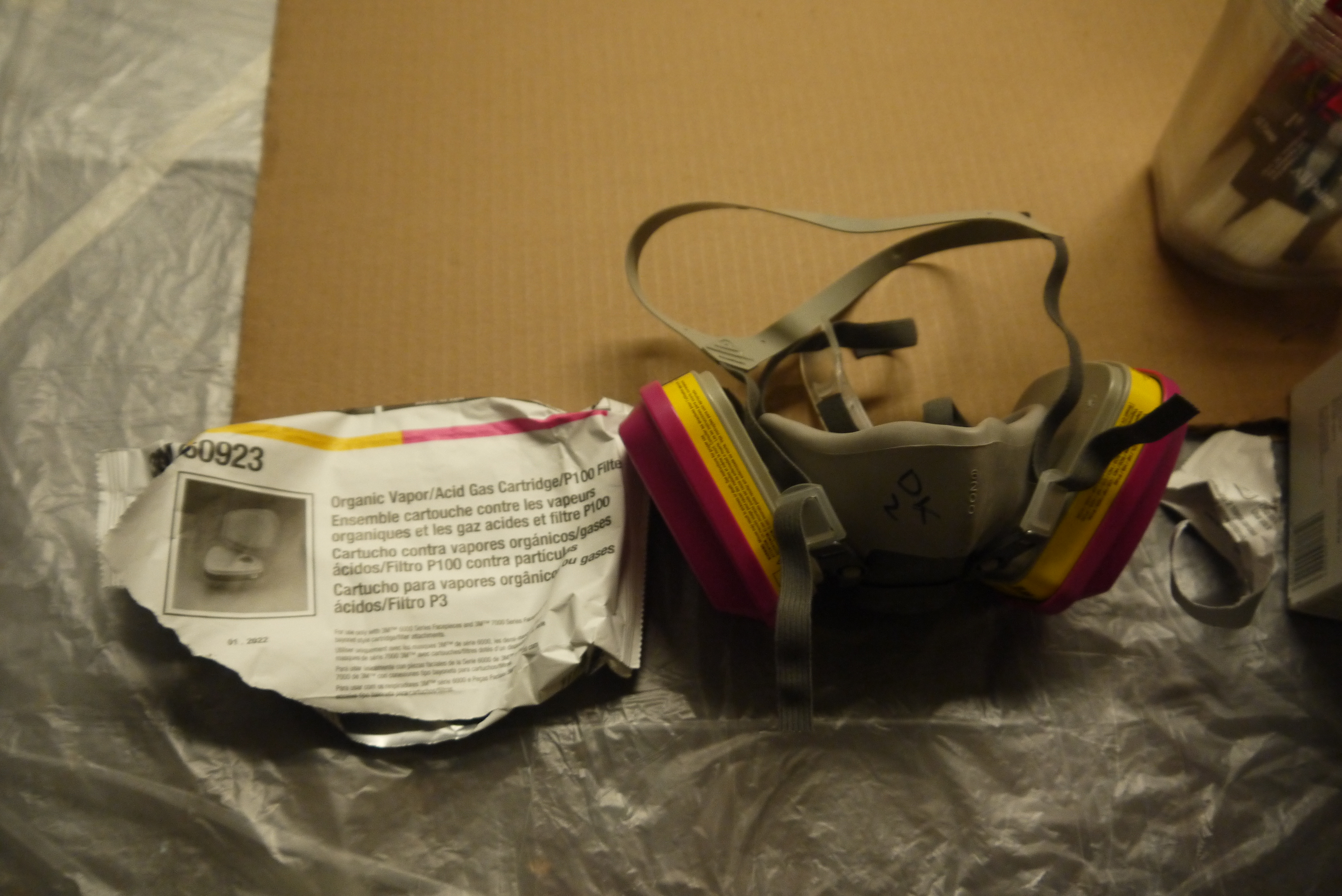 Protective
Gear Protective
GearAs this epoxy paint was quite toxic and recommended air filtration, fortunately pills hardware had some of these fancy respirator filters in stock. Yowzas, rated for acid gas? OK. |
  The
painting began, a 'ratio metric container' was chosen
and the mix of 3 parts paint 1 part hardener was used.
Nominally this is supposed to be thinned by some
hella-solvent that was probably sold in the 90's,
however, due to not having that and reading about it
after having set up, painting with the non-thinned
mixture was attempted. The
painting began, a 'ratio metric container' was chosen
and the mix of 3 parts paint 1 part hardener was used.
Nominally this is supposed to be thinned by some
hella-solvent that was probably sold in the 90's,
however, due to not having that and reading about it
after having set up, painting with the non-thinned
mixture was attempted. |
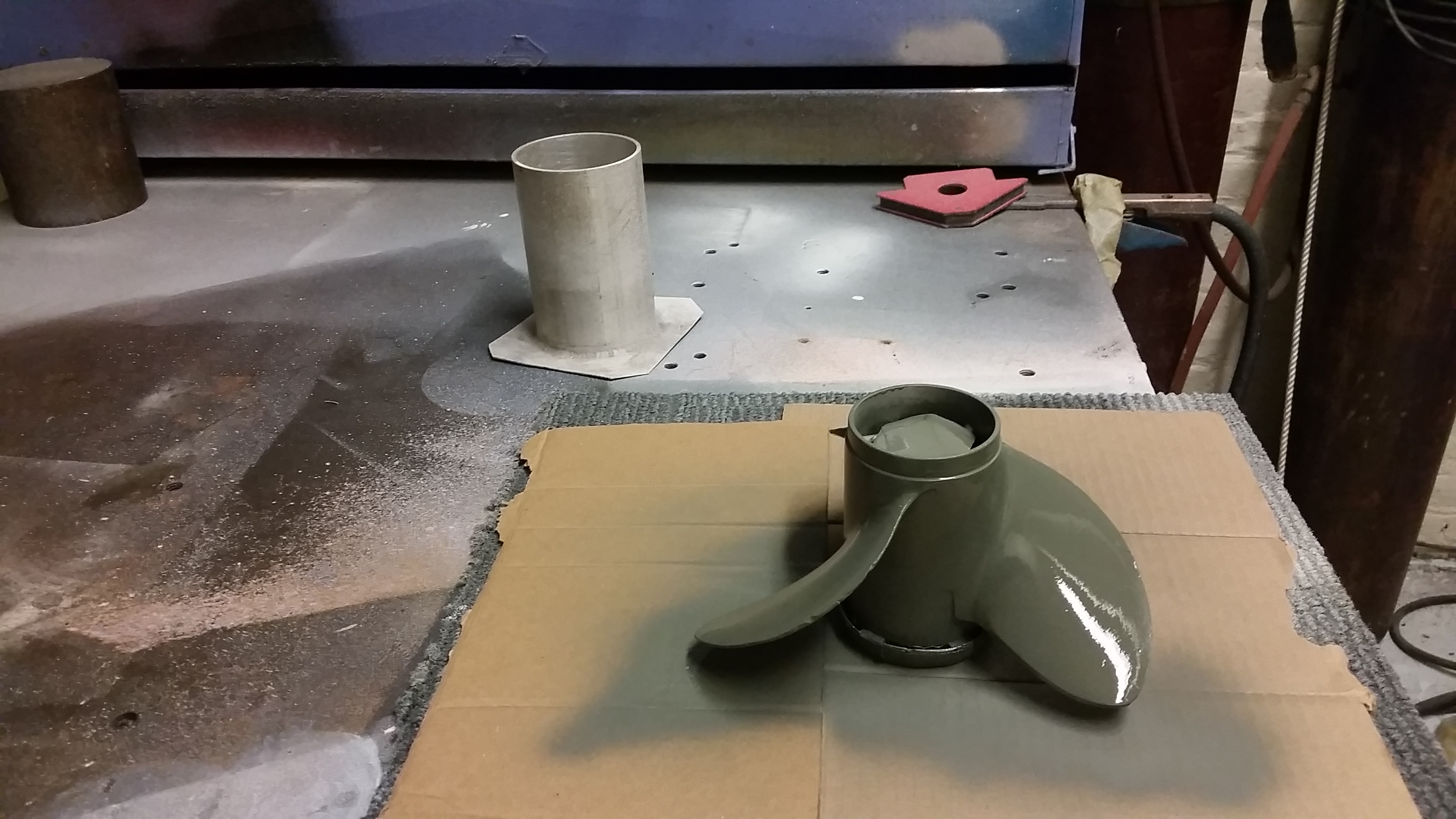
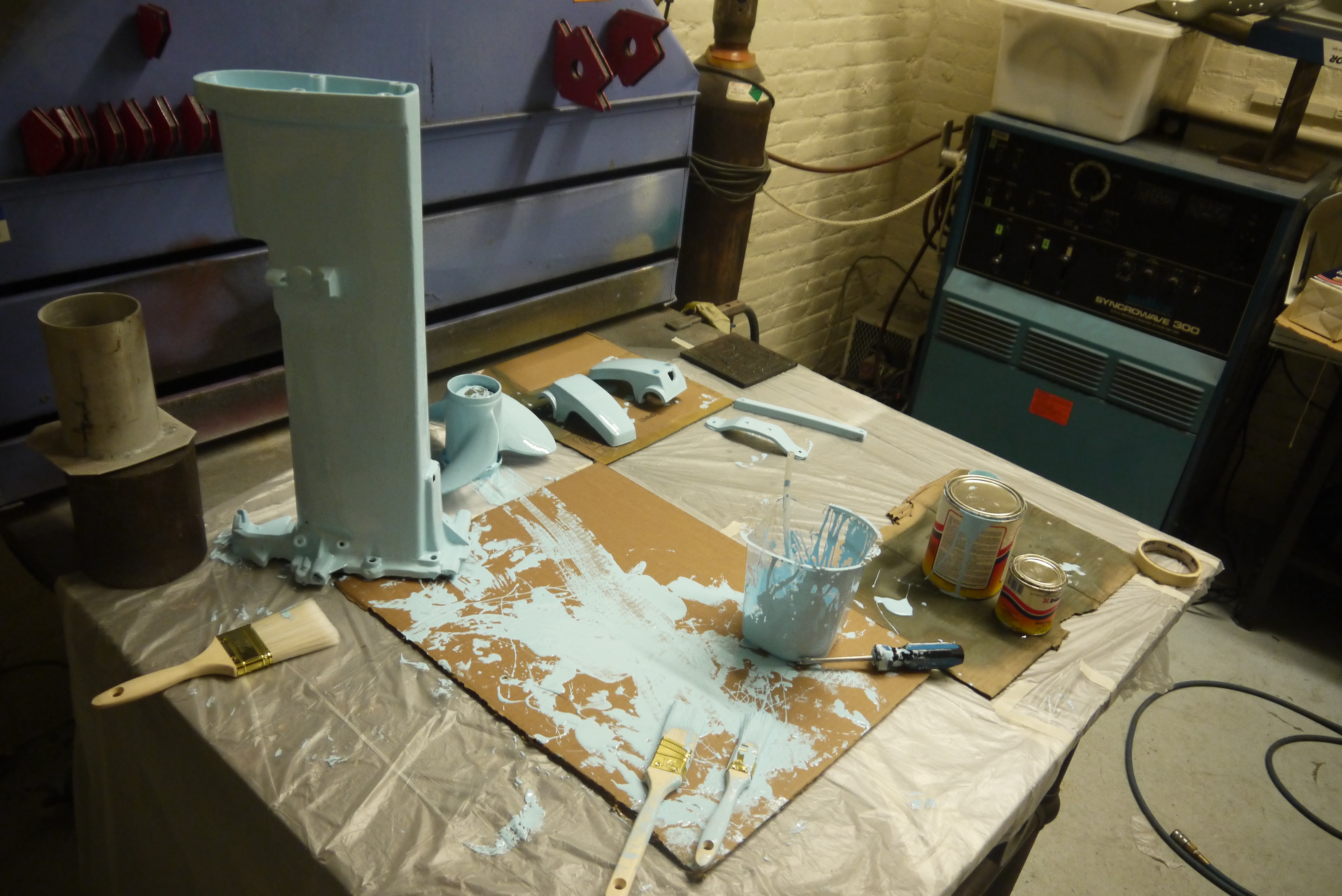
 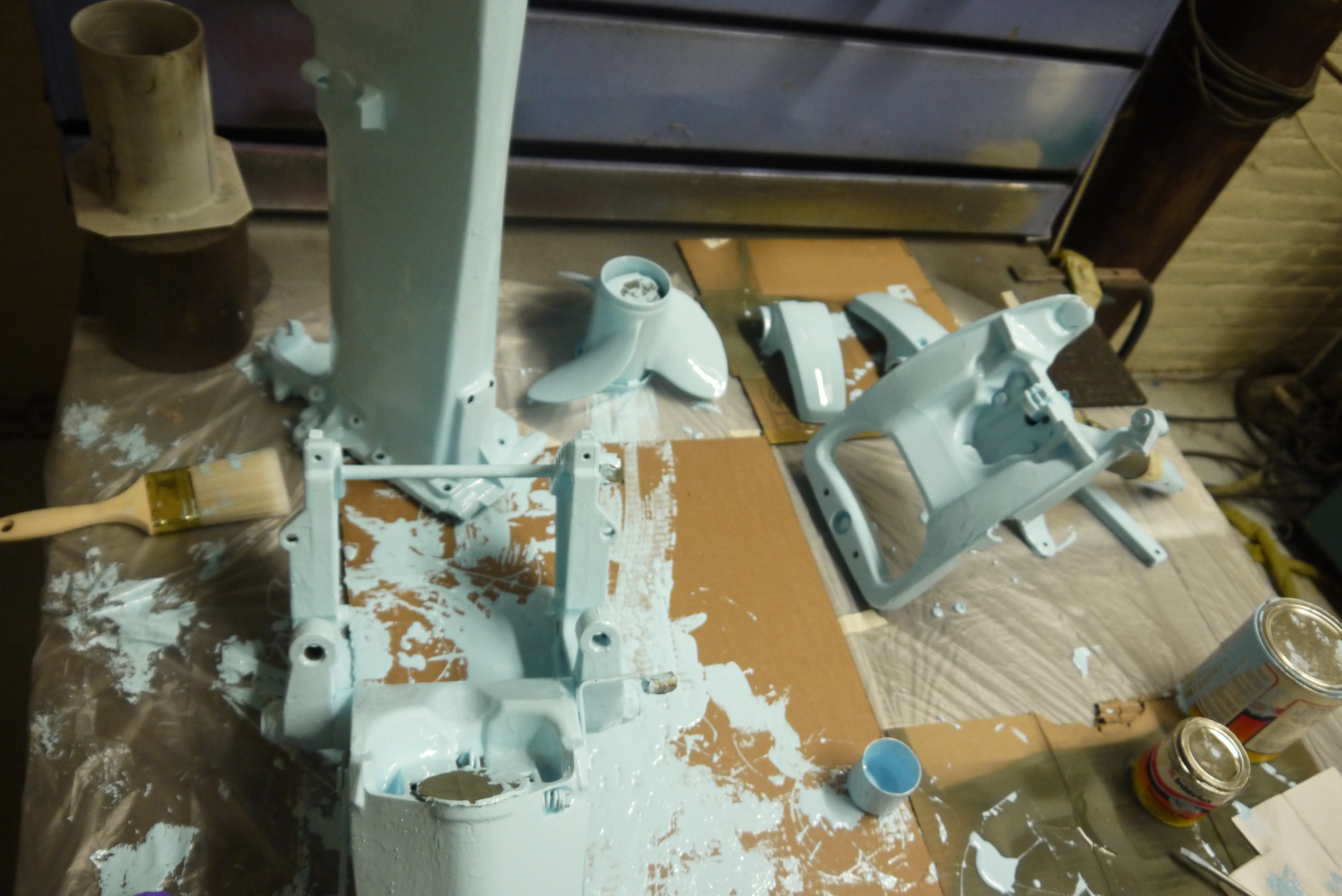 BEBY BLUE BEBY BLUEThe epoxy paint claimed to 'set overnight' and get tacky within 3 hours, however, without the 20% thinning agent, it set QUITE QUICKLY and got quite sticky. Otherwise, the outboard painting went well, albeit slightly runny. Most of the parts were fully covered, some required a flip and paint ~12 hrs later. |
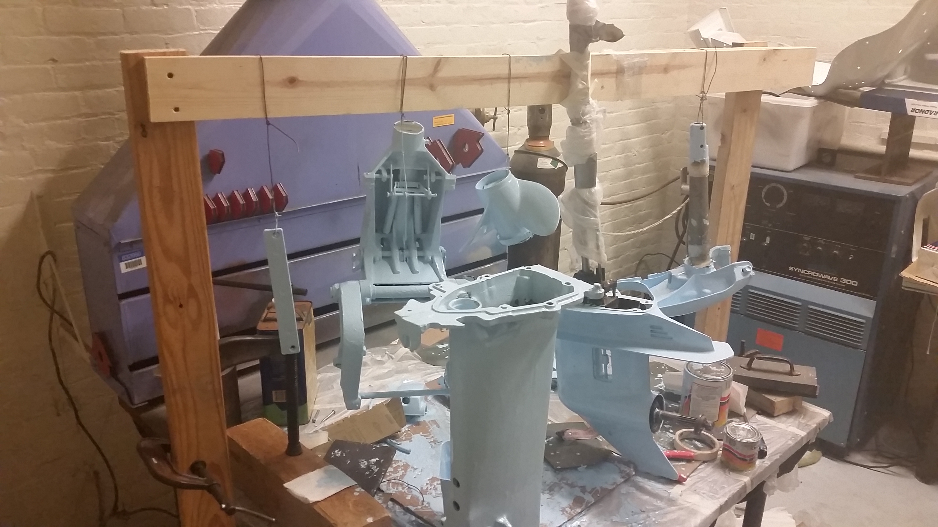  AN IDEA WAS FORMED AN IDEA WAS FORMED If the parts were hanging, getting a better coat would be way less difficult, so, as things go, a makeshift clothesline of parts was born. With the dangling parts, easily re-positionable by glove, everything was covered. The thinned-out goo was quite lubricious and required a bit of paint drip mitigation. Otherwise everything was going swimingily. |
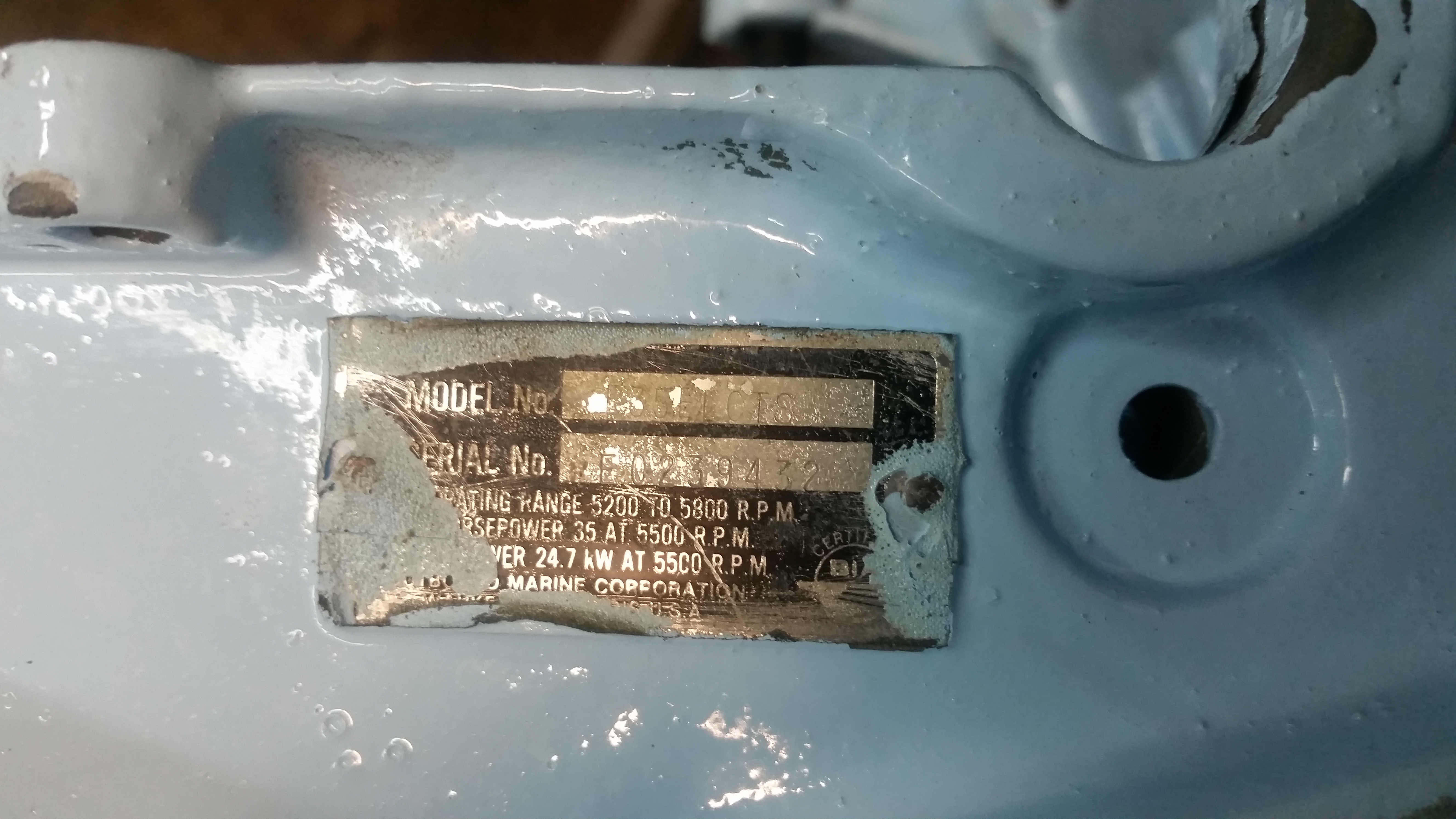 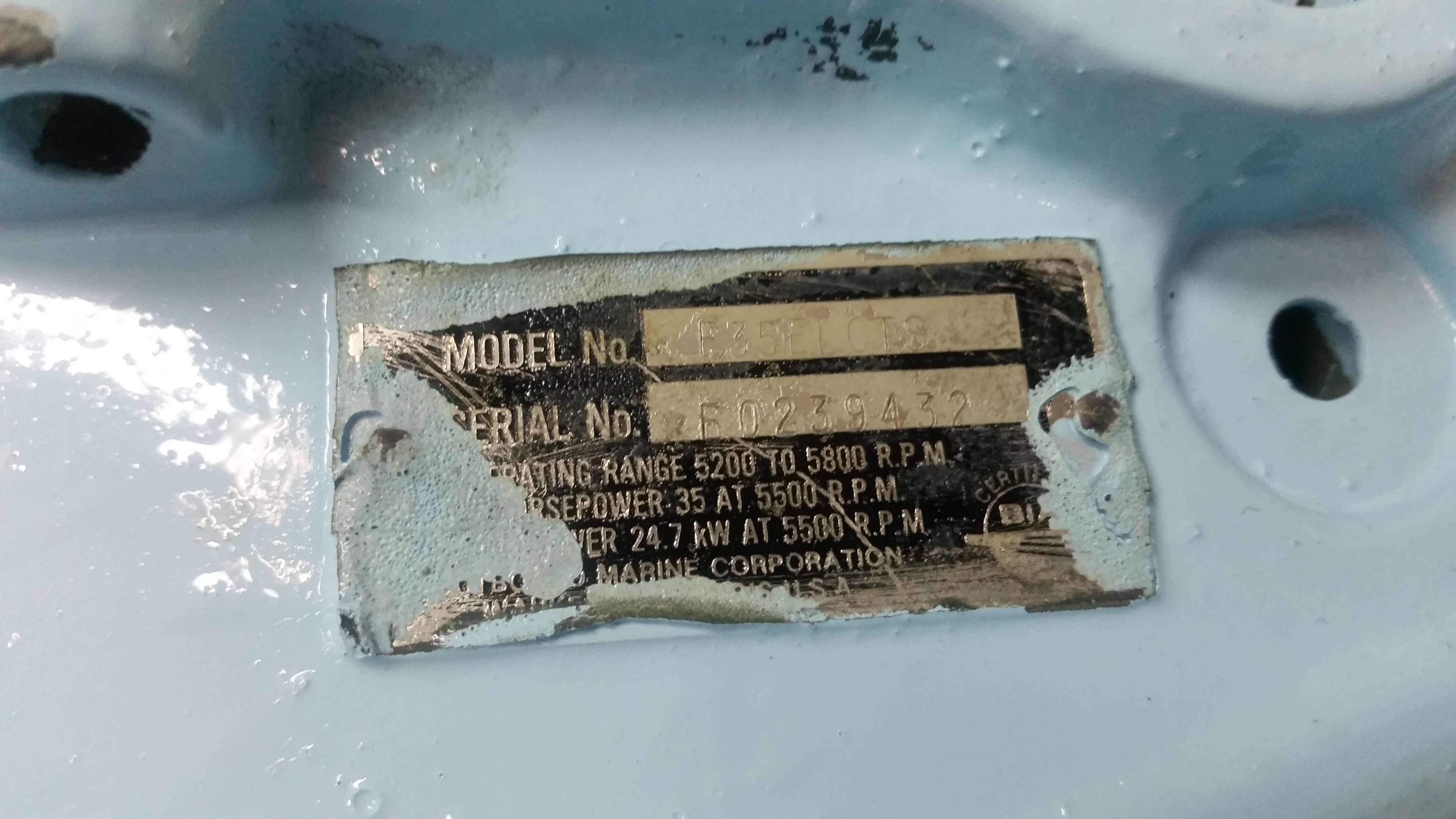 Model # For Reference Model # For ReferenceI taped over (poorly apparently) the model and serial #, which are included here for reference. This does point toward this being a 35HP outboard, at 5500 RPM. Its hard to make out but this indicates that this outboard is an E35ELCSM Evinrude. There are still parts available online [link] |
  There
are a surprising
number of parts in this contraption. Shown
right is an excerpt from a repair manual. Quite a lot of
parts to make this thing work. Bearings bushings gaskets
and seals oh my! Given that the engine bit is, in
its own, a huge pile of components just the lower is
quite a bit of hardware. There
are a surprising
number of parts in this contraption. Shown
right is an excerpt from a repair manual. Quite a lot of
parts to make this thing work. Bearings bushings gaskets
and seals oh my! Given that the engine bit is, in
its own, a huge pile of components just the lower is
quite a bit of hardware. |
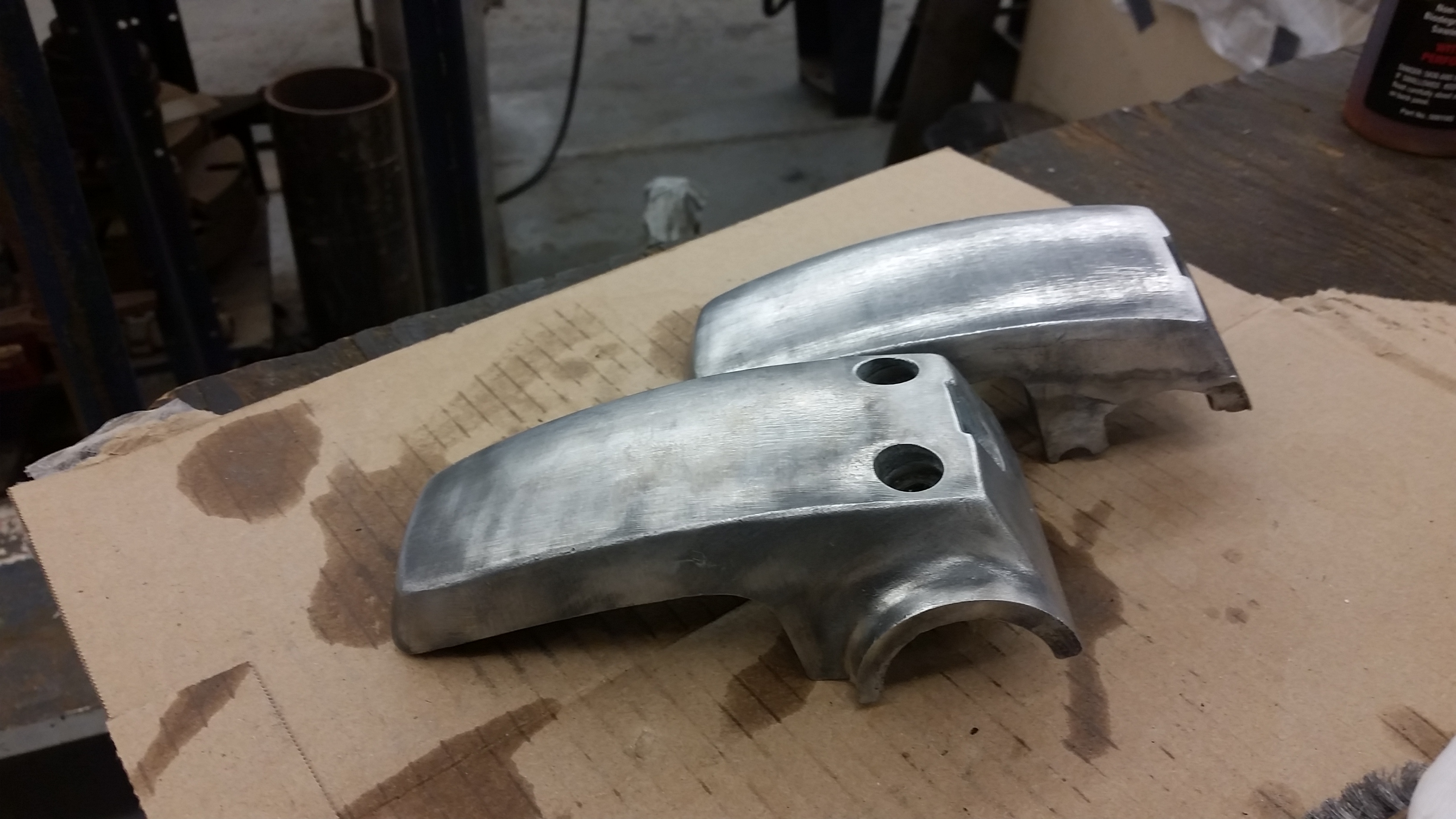
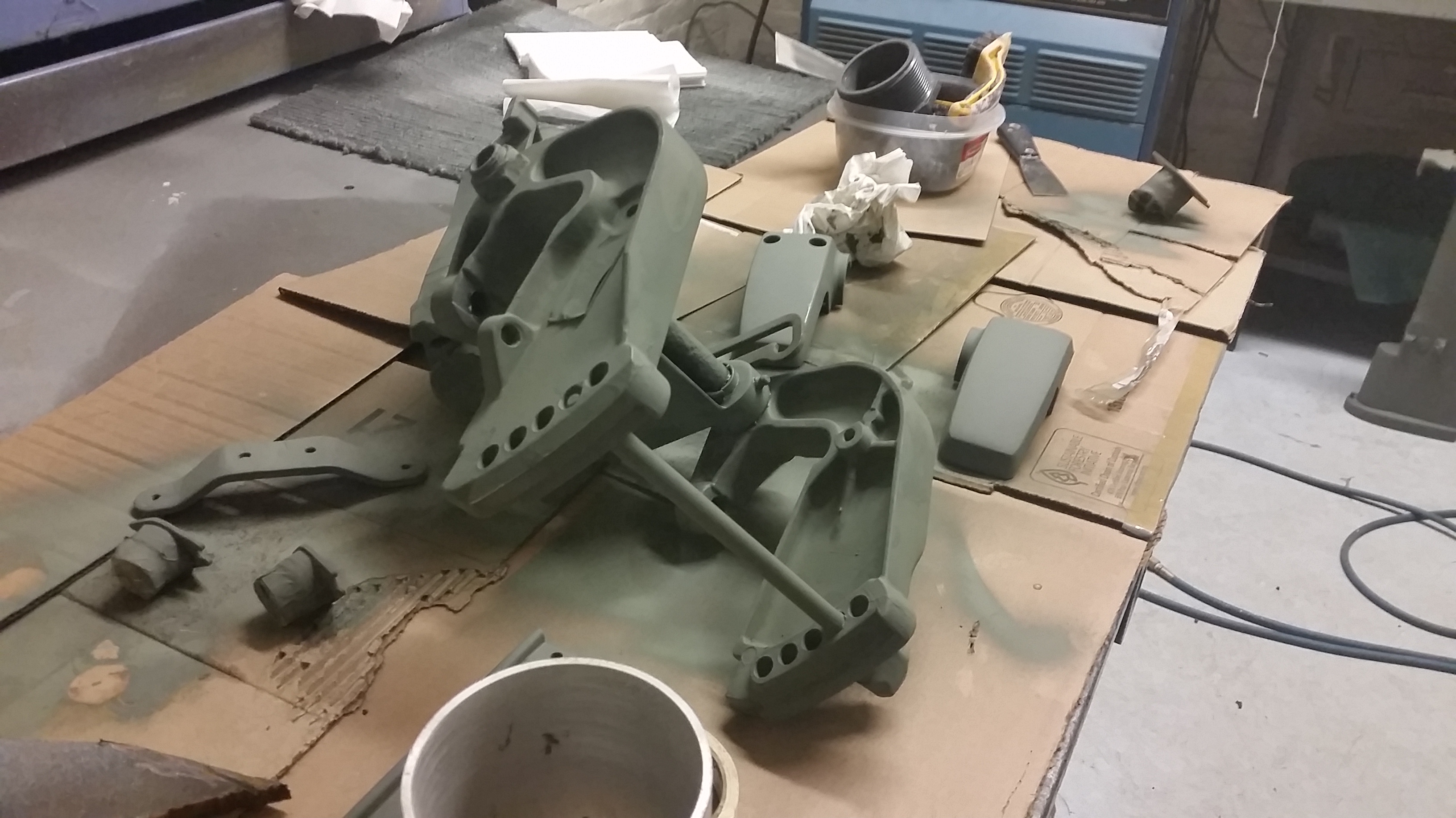
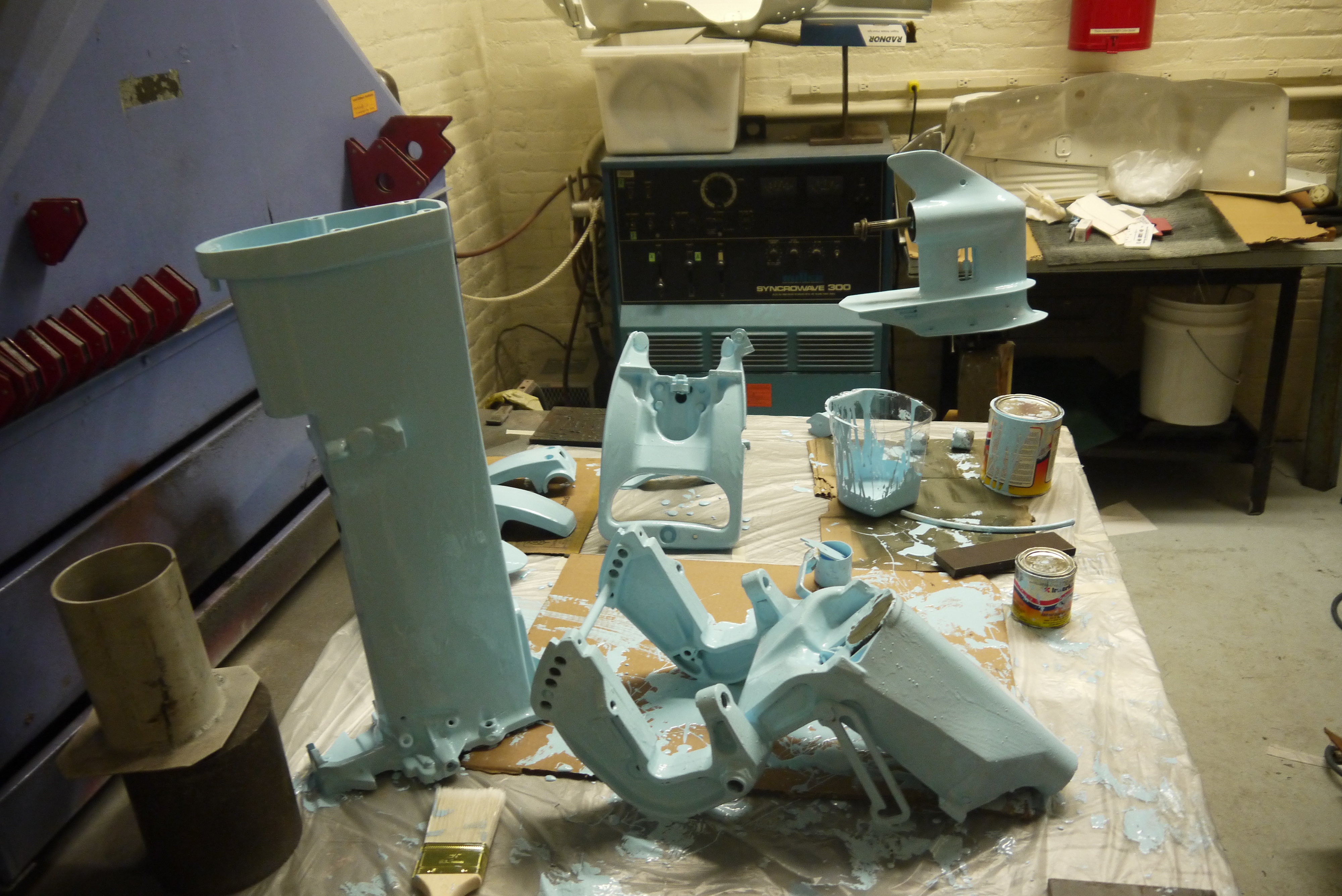
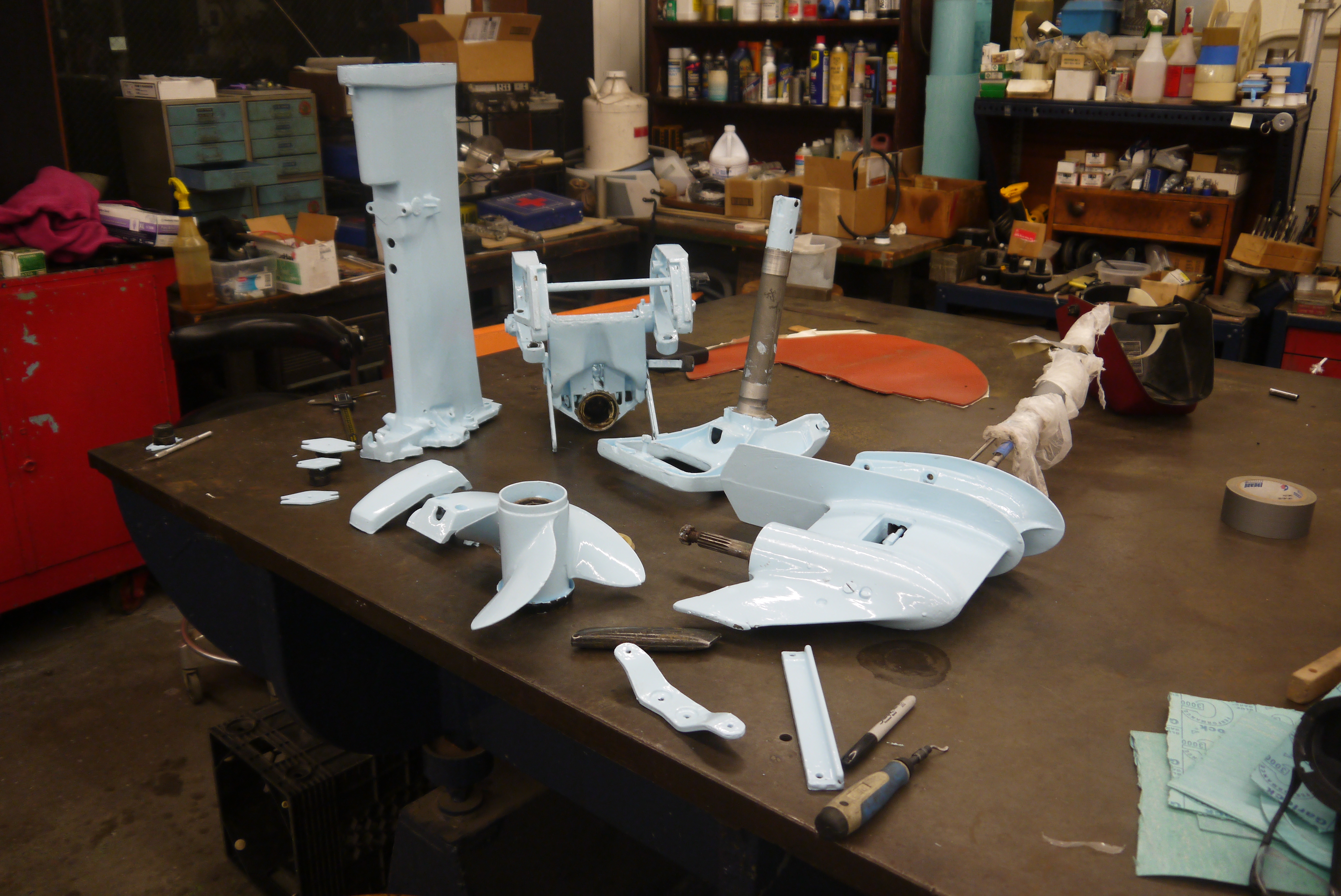 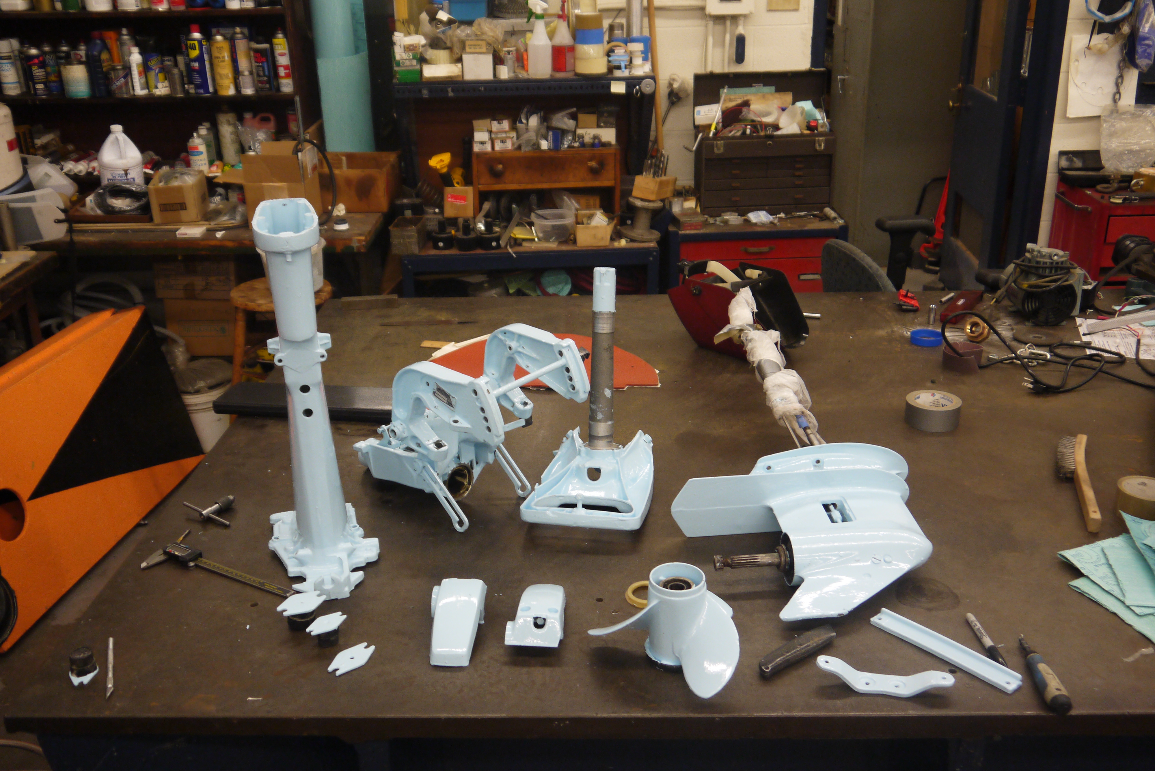 Here's
the assortment of parts after sitting to dry for a
weekend. Quite good all things told, the older marine
paint seemed to still work well enough and all that was
left was to clear out any plugged holes and mating
surfaces and re-assemble. Here's
the assortment of parts after sitting to dry for a
weekend. Quite good all things told, the older marine
paint seemed to still work well enough and all that was
left was to clear out any plugged holes and mating
surfaces and re-assemble. |
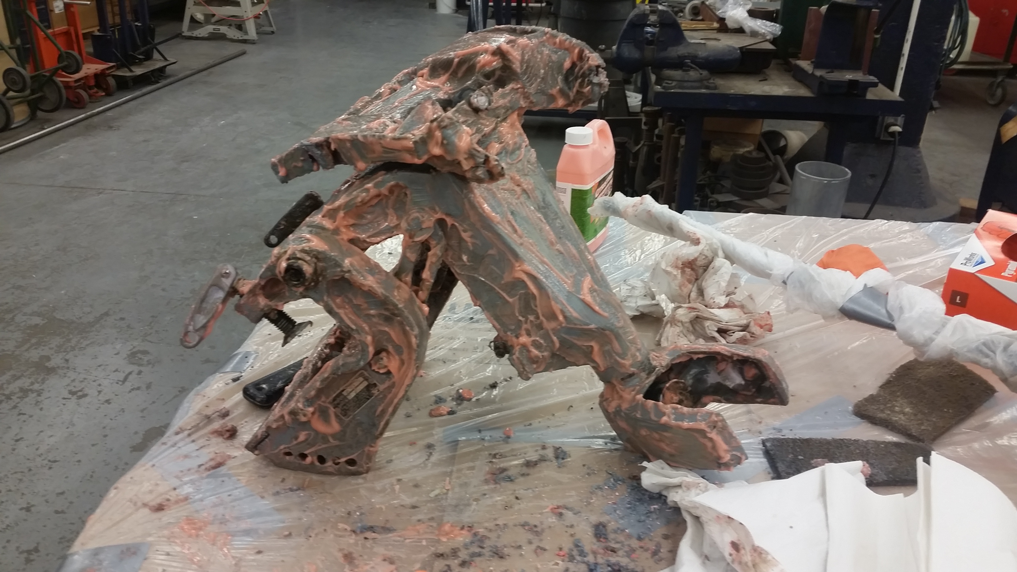
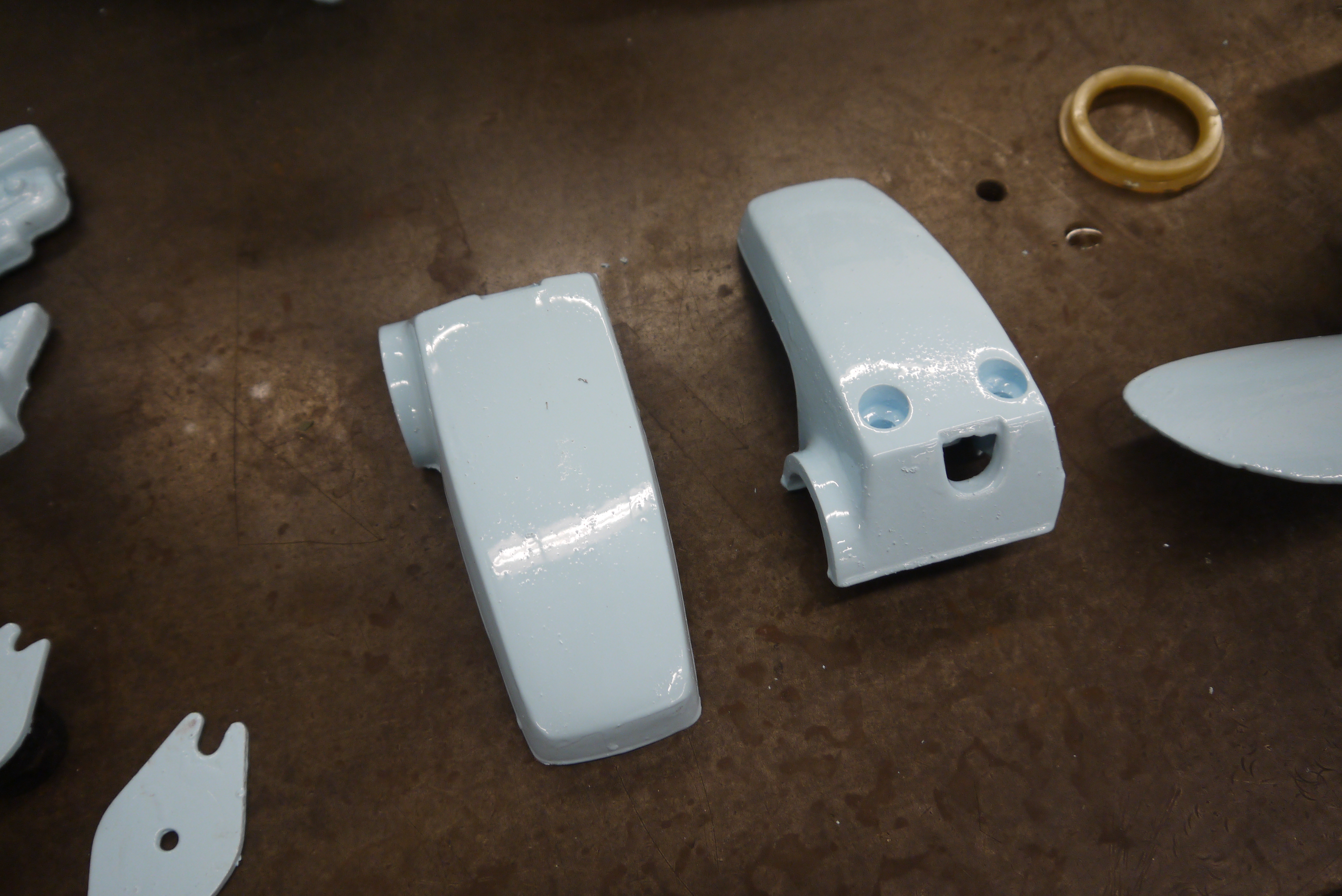  One
of the real challenges was the number of inside cavities
and the like in a few of the parts, as a result there
were a number of paint, flip, paint, etc. Still quite
happy with how it turned out. One
of the real challenges was the number of inside cavities
and the like in a few of the parts, as a result there
were a number of paint, flip, paint, etc. Still quite
happy with how it turned out. |
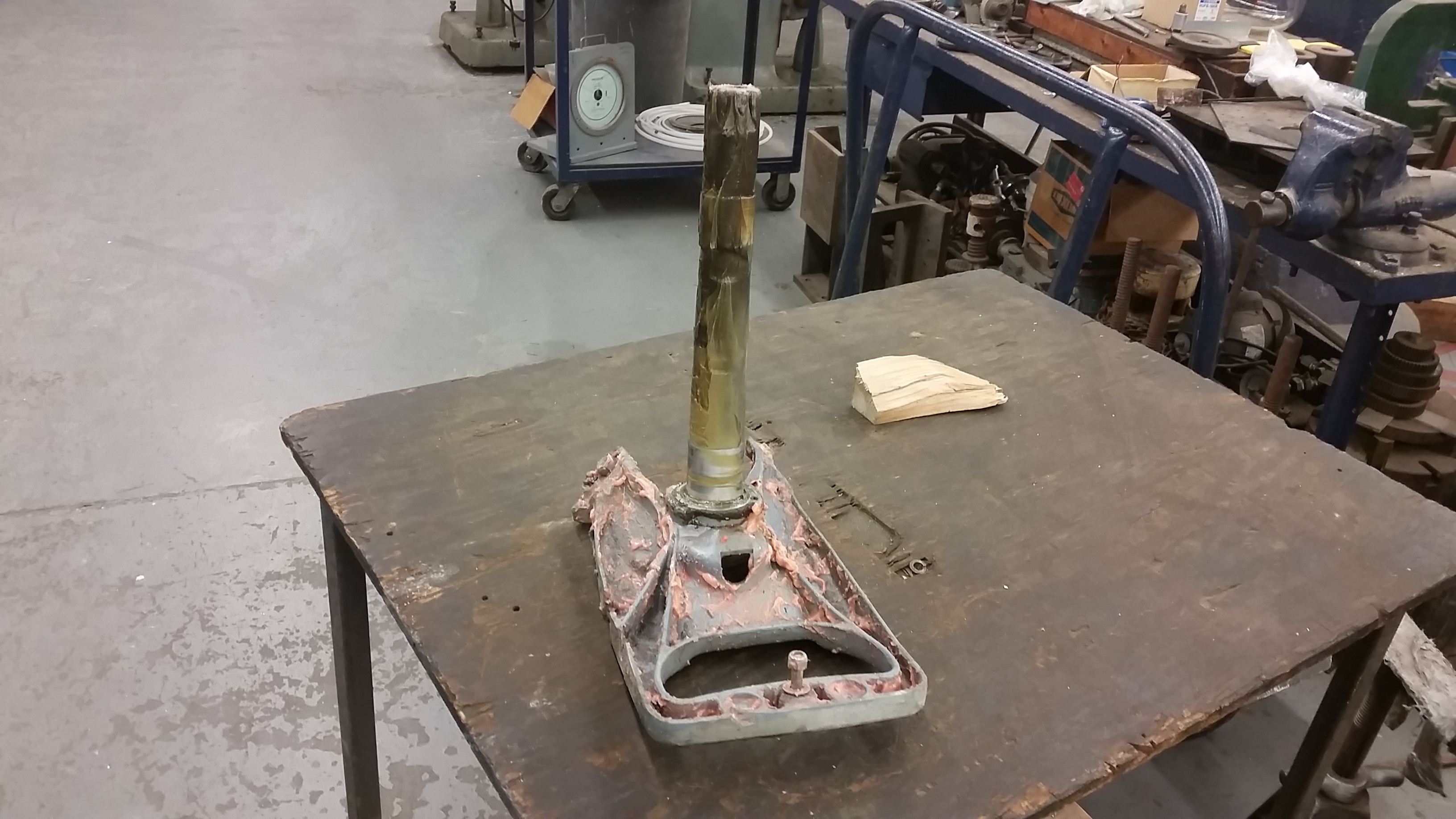
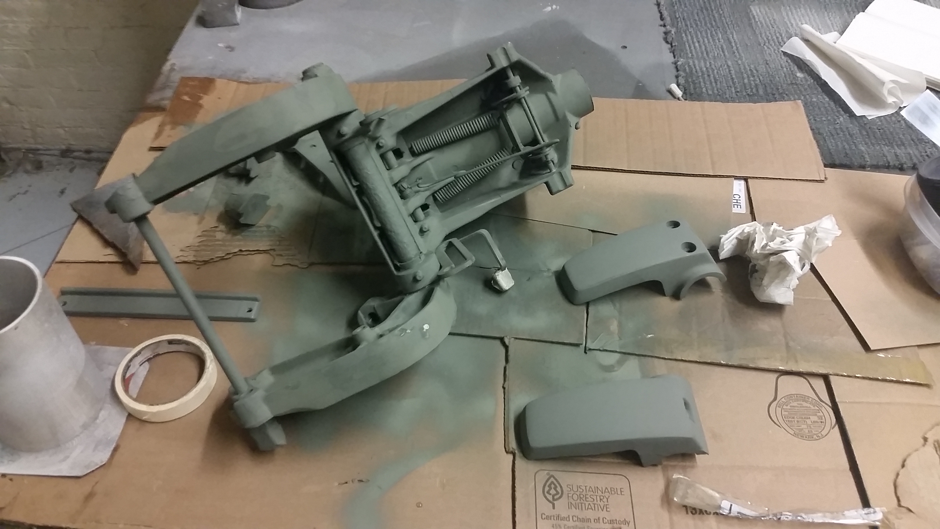
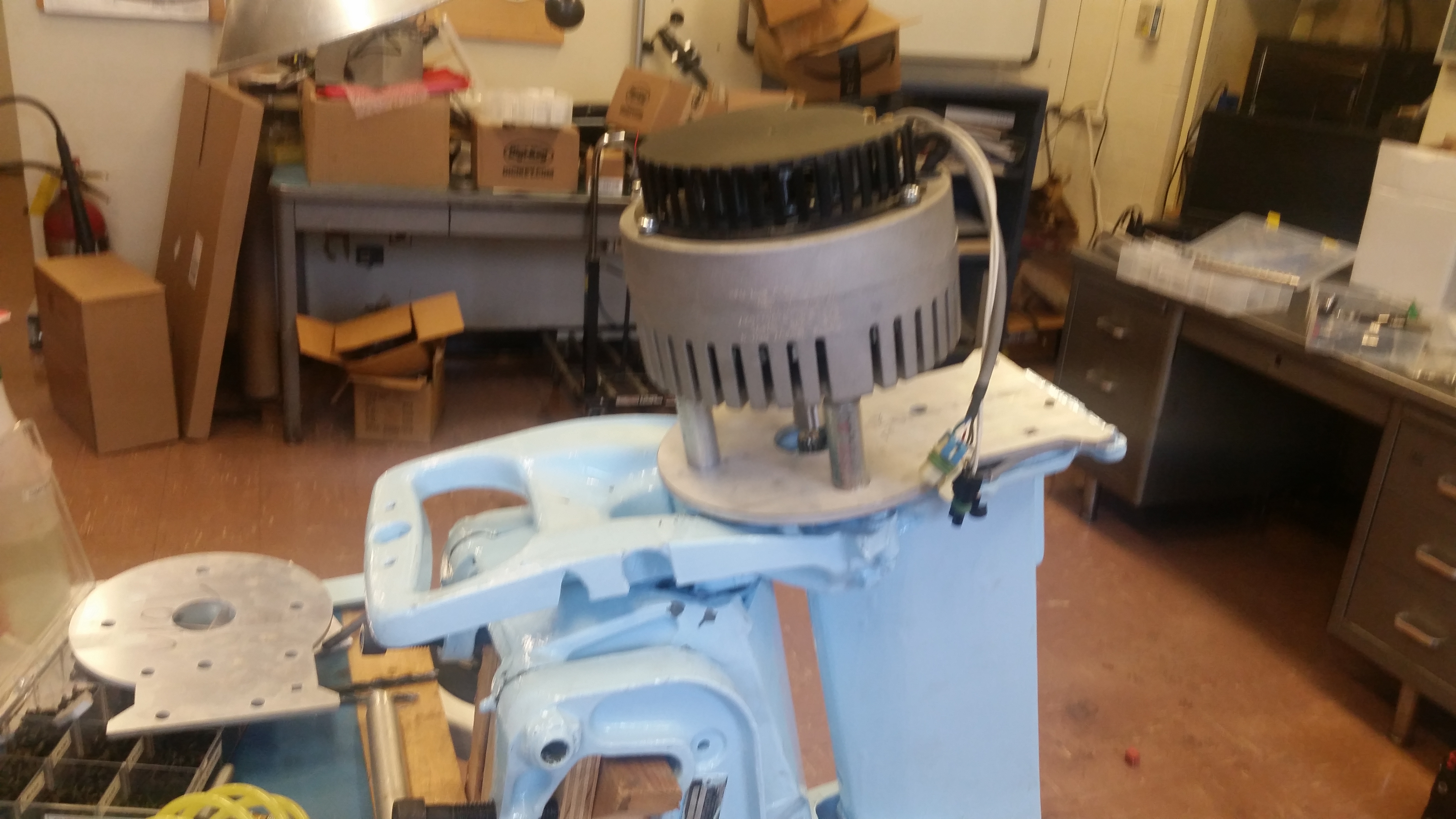
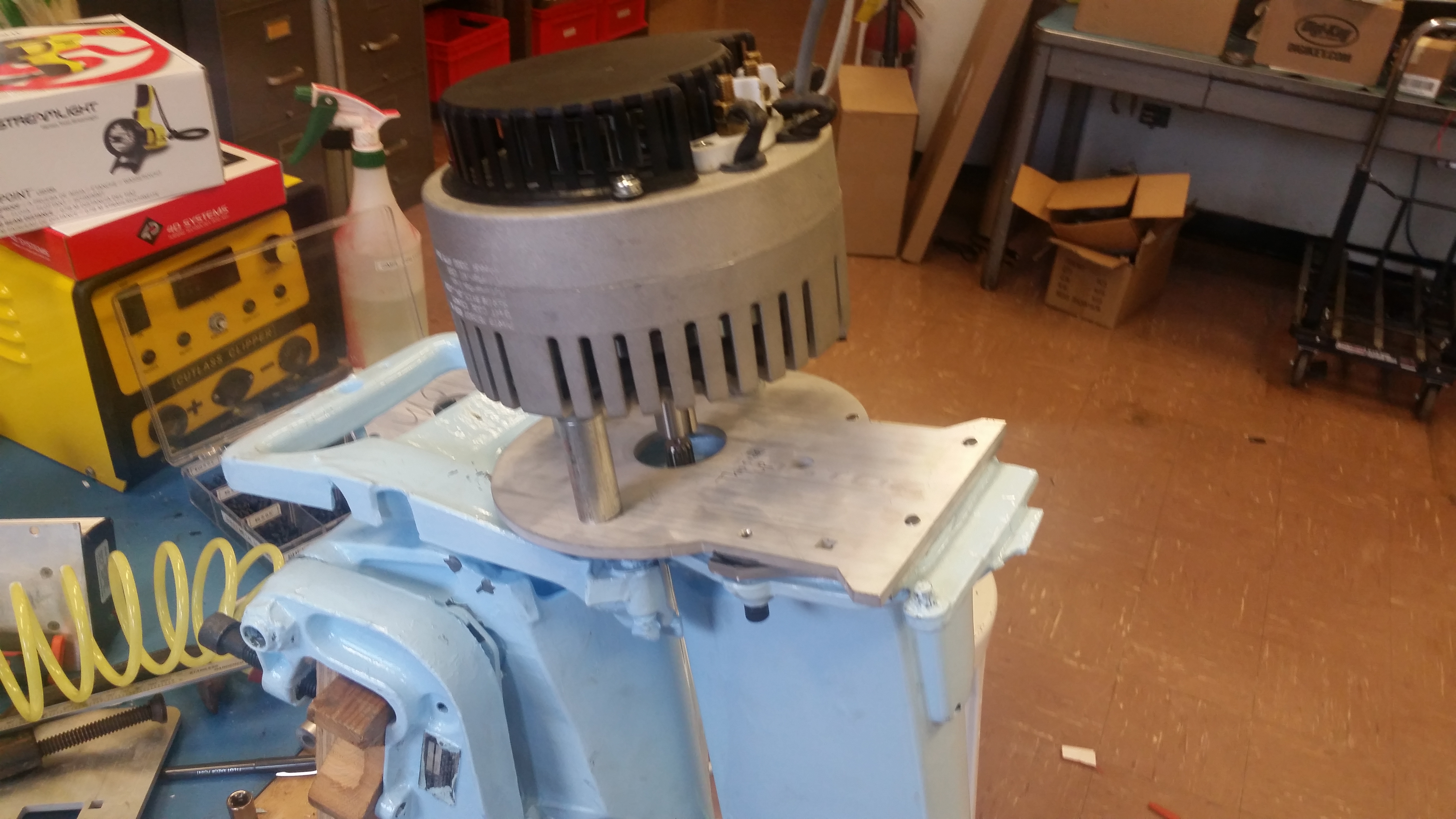
  Everything
cobbled back together somehow still resembled an
outboard! The rubber vibration mounts had almost all
succumbed to age and fallen apart, but should be rescued
in a future episode. Everything
cobbled back together somehow still resembled an
outboard! The rubber vibration mounts had almost all
succumbed to age and fallen apart, but should be rescued
in a future episode. |
  There
were some spots that didn't take well to painting, one
of the adjustment levers got bound up with paint and
when I moved the lever, it came un-done. The actual
pivot that the boat makes was also quite resistive,
admittedly its mounted a bit offset to a large steel
table in this setup. There
were some spots that didn't take well to painting, one
of the adjustment levers got bound up with paint and
when I moved the lever, it came un-done. The actual
pivot that the boat makes was also quite resistive,
admittedly its mounted a bit offset to a large steel
table in this setup. |


| An Early test of the Electric Outboard V2 |
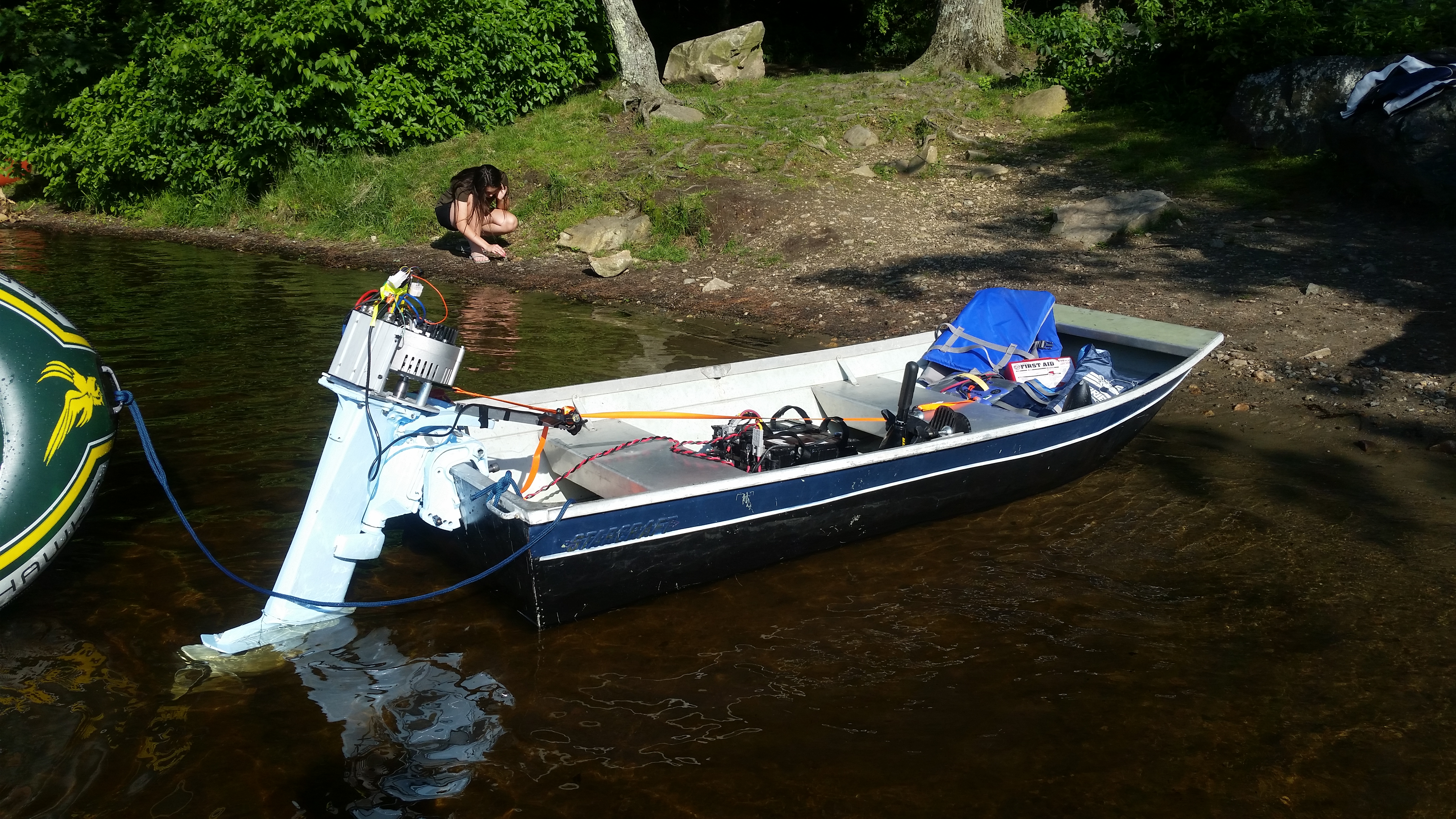
  For the first outing of
the year there was a proper retreat + outboard testing
shindig. Shown is the ~8' Jon boat with a bunch of
lake-cruft, including a PID controlled charcoal BBQ, a
rotary meat apparatus and an inflatable unicorn. For the first outing of
the year there was a proper retreat + outboard testing
shindig. Shown is the ~8' Jon boat with a bunch of
lake-cruft, including a PID controlled charcoal BBQ, a
rotary meat apparatus and an inflatable unicorn. |
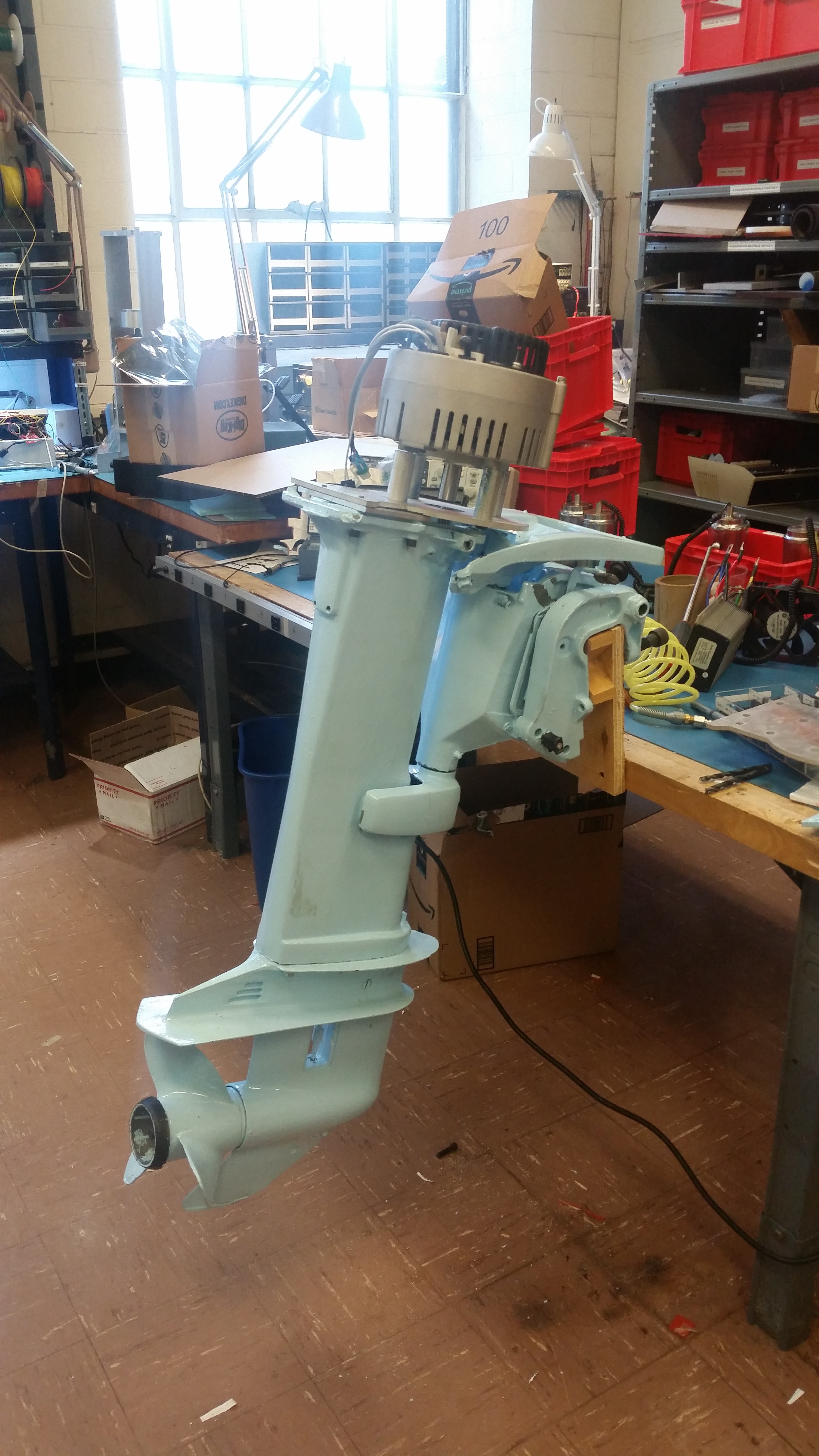
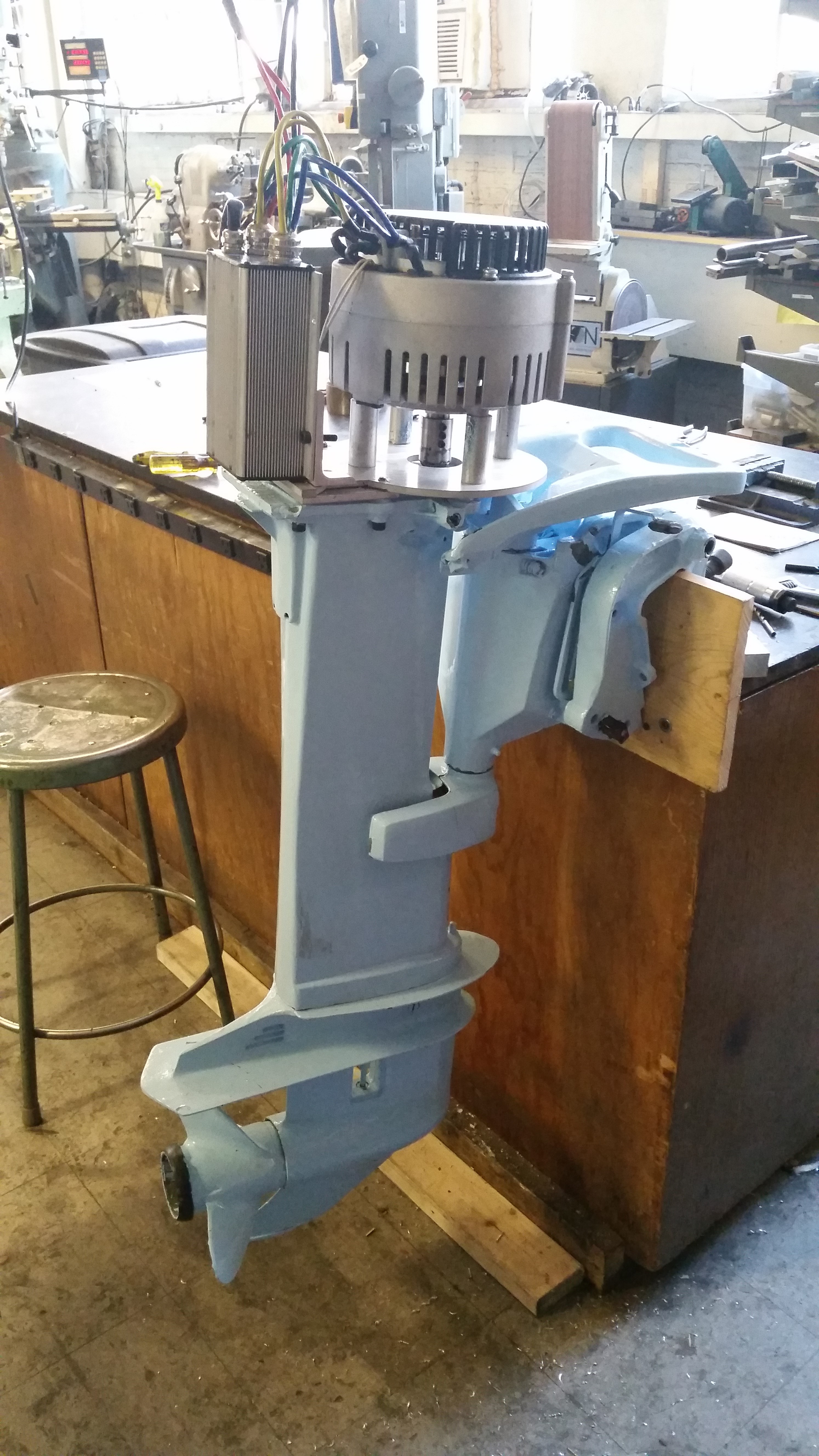
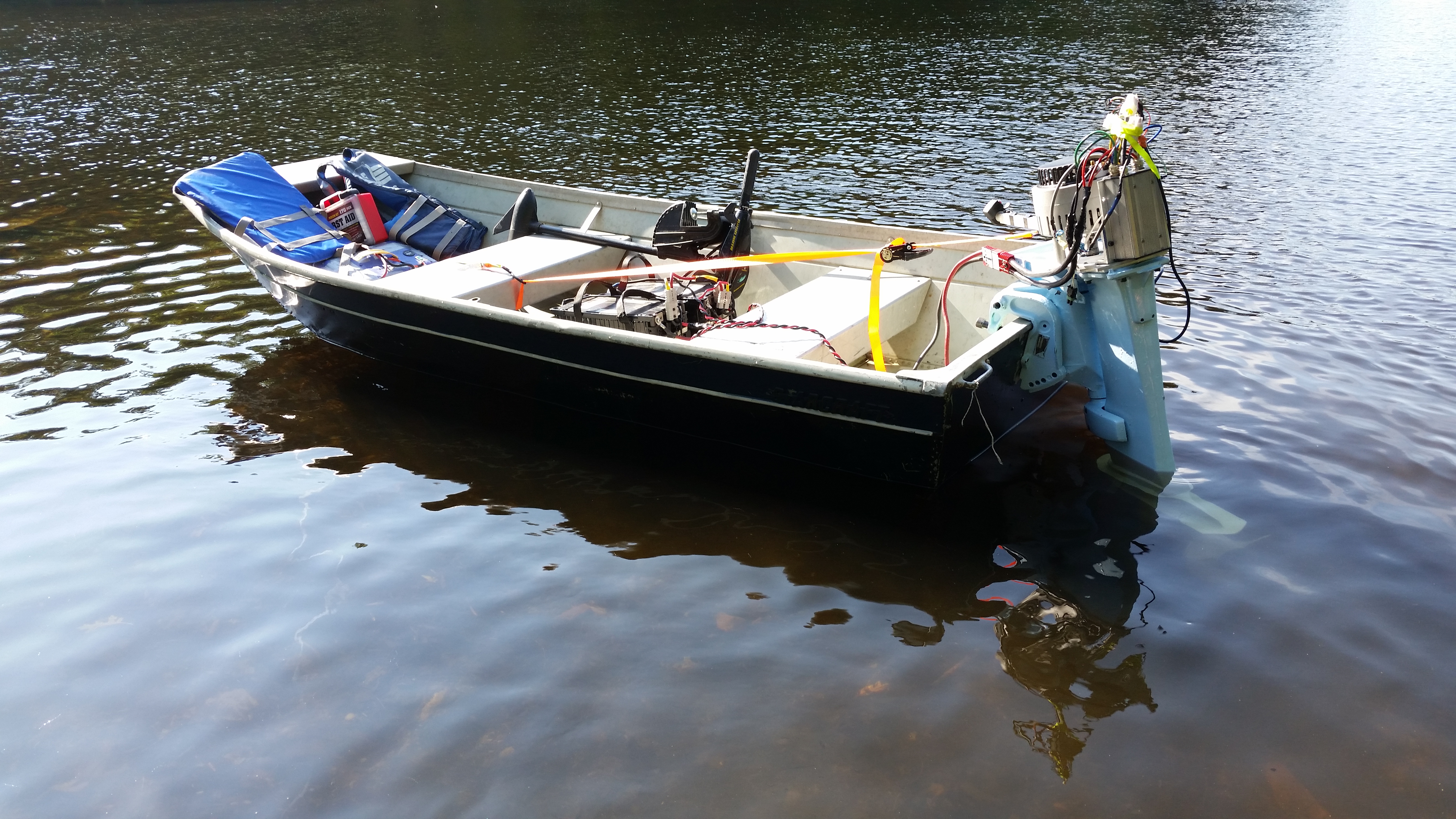 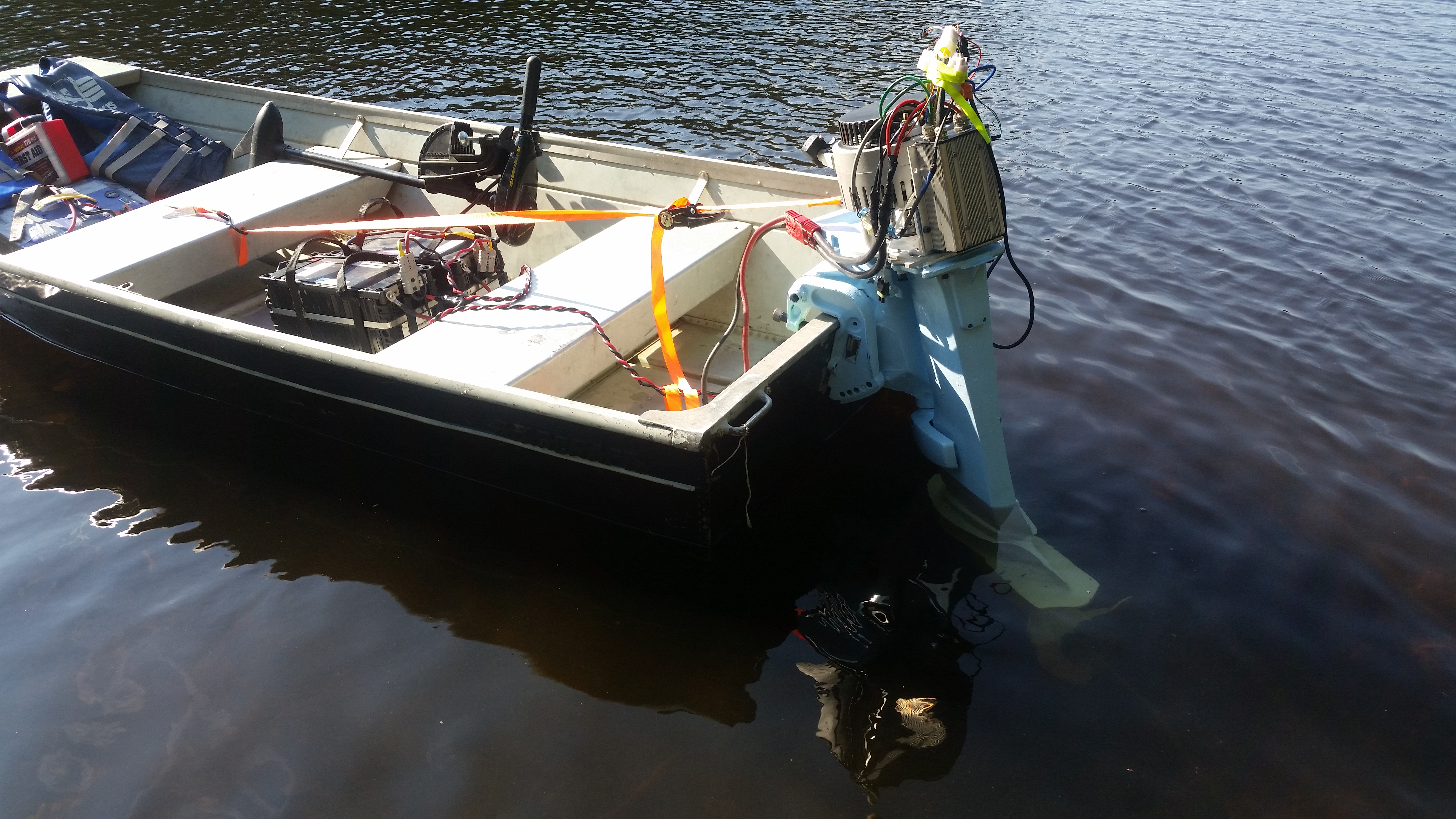 After transporting
everything to a spot to camp out, I went back for the
outboard. Note how low the long shaft outboard sat in the
water. I later found that prop positioning, angle and
height heavily affect the performance and speed
characteristics. It was also apparent that the transom
mount (or lack there of) was not even close to being
suitable for the amount of force the new outboard
could push. After transporting
everything to a spot to camp out, I went back for the
outboard. Note how low the long shaft outboard sat in the
water. I later found that prop positioning, angle and
height heavily affect the performance and speed
characteristics. It was also apparent that the transom
mount (or lack there of) was not even close to being
suitable for the amount of force the new outboard
could push. |
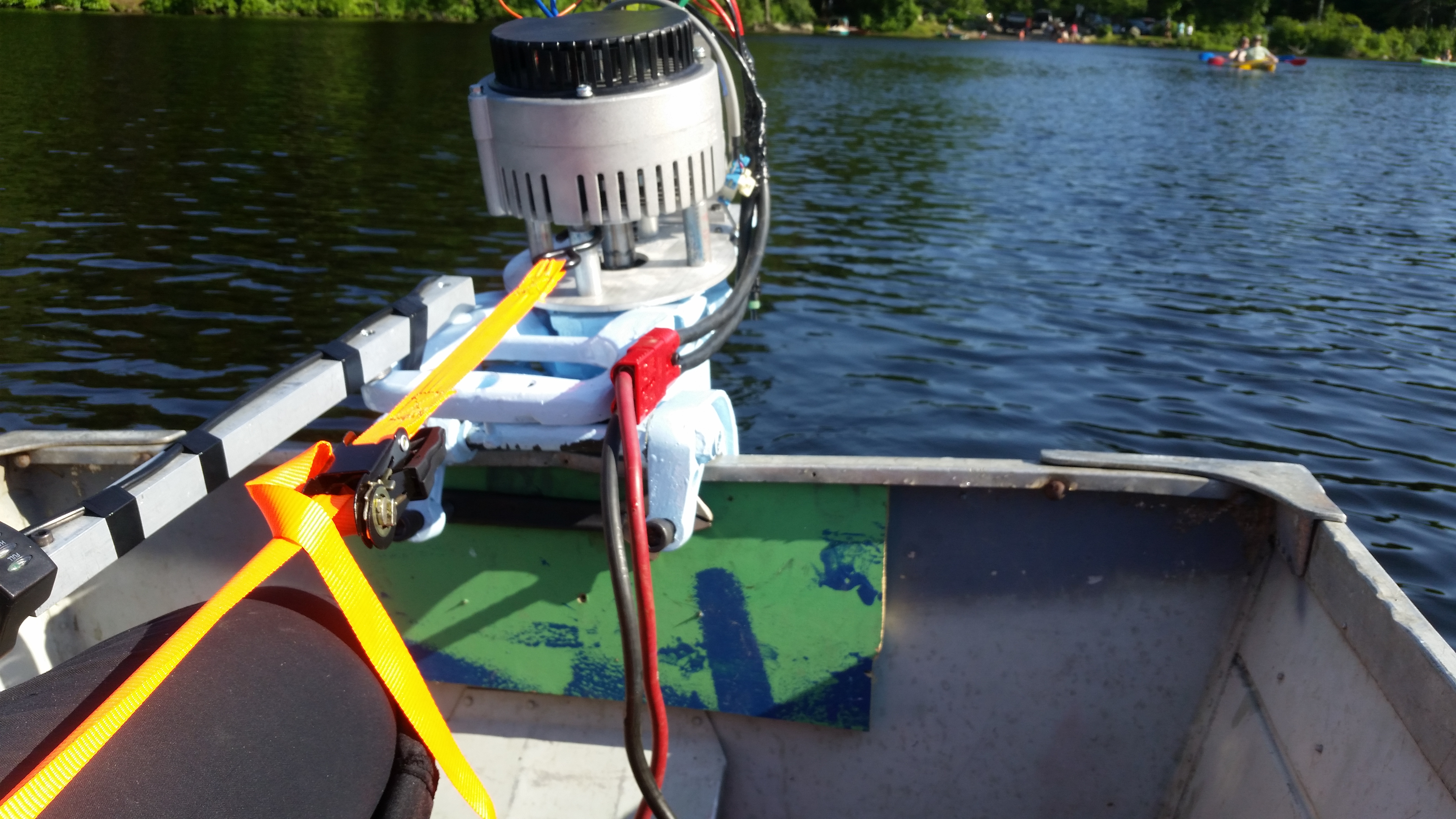 A ratchet strap was added
to help counter the outboard torque, but alas, getting
to 30% throttle resulting in some fairly harrowing
torque. A ratchet strap was added
to help counter the outboard torque, but alas, getting
to 30% throttle resulting in some fairly harrowing
torque. |
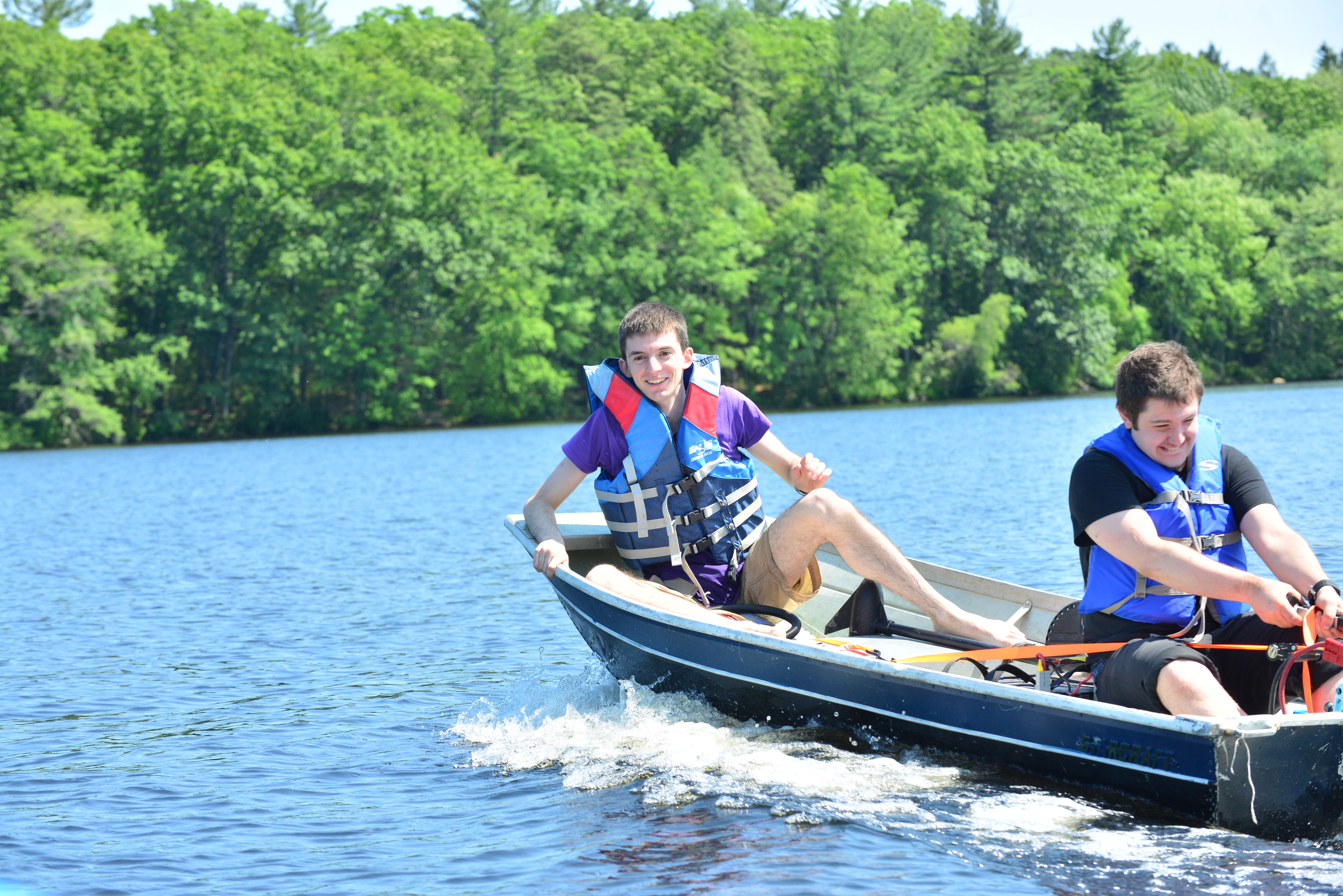 It
was much more peppy and exciting
than i had previously encountered. Note that the handle,
which was fixed-mounted to the outboard was a bit
strenuous to handle. Accelerating hard would launch a
bit, and without having control over the angle of
attack, the front would launch up a bit. It
was much more peppy and exciting
than i had previously encountered. Note that the handle,
which was fixed-mounted to the outboard was a bit
strenuous to handle. Accelerating hard would launch a
bit, and without having control over the angle of
attack, the front would launch up a bit. |
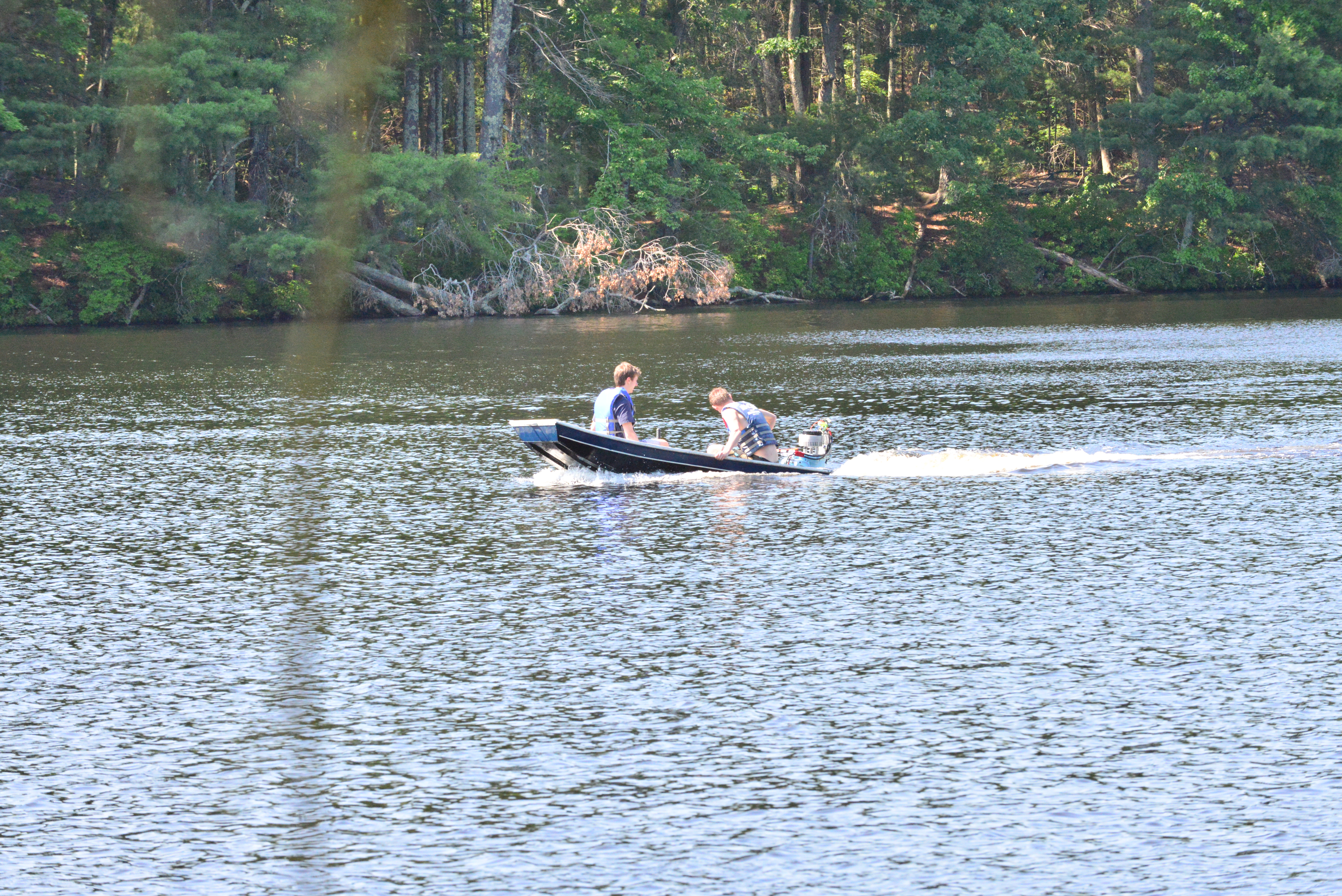  Here's
some early shots of us all zooming about the nearby
resivour* (yes electric watercraft are permitted). Note
how low the actual outboard sat under the water surface.
More to come on fixing that issue. Here's
some early shots of us all zooming about the nearby
resivour* (yes electric watercraft are permitted). Note
how low the actual outboard sat under the water surface.
More to come on fixing that issue. |
| Notes from the first test |
| * A better transom mount is required. During the first test, I relied on the existing, small wooden transom mount. It worked splendidly for a small 12v trolling motor, but became an issue whenever the outboard was pushed to more than ~30% power, as the rear of the boat started to become less structural. A new mount that ties together the back of the rowboat would really make a difference. For the test, the torsional forces were mitigated temporairally by adding a ratchet strap to the center seal area, but the amount of force applied but it was still rather tenuous, all things considered. Mechanically reinforcing the back and making attachment points for carrying the forward force into the hull is a must, moving forward. |
| * Tilt adjust on the transom
is a good idea The actual 'trim' that the outboard had in-water is actually fairly important as it nominally defines how the watercraft wil perform. After the first test I consulted a few colleagues with more time at sea than myself, as it turns out 'trimming' is its own art to an extent. |
| * The height of the prop is also fairly
important. This particular outboard is a 'long shaft' style outboard, which is intended for mounting higher up on a watercraft. As my rowboat is incredibly low to the water, this doesn't work out that wonderfully as the two combined result in a lot of hydro-drag. |
| *Hear me out, hydrofoil The results of this first test were curious, mechanically the prop turned, the motor was happy and the electronics stayed under control. The big issue was the outboard being incredibly long, it caused quite a lot of hydro drag being so far underwater. Lets start with a conventional setup, a watercraft that would take a 35hp outboard is generally a bit higher off the water and generally 12-18' long. Lets start with the assumption that this watercrafts transom is 6-8" higher off the water surface than my row boat. Now, lets shift to a 'long body' outboard, which, research suggests is 10" longer than the same outboard model that is not the long-body style. We're now seeing a roughly 16-18" difference in prop height. This is a significant difference in prop height and resulted in a bit of drag. Not all is lost though, 16" is enough to lay in a small hydrofoil under the craft. I'm talking a set of wings to hold the craft out of the water and up in the air. This would significantly reduce the hydro load on the craft while also making proper use of the long body'ed outboard. Its not unheard of to add a hydrofoil to smaller craft, competitive sailing folk do it frequently. A curiosity for another weekend indeed. |
| * Maybe
Pontoons is a good intermediate solution to twiddling
with a hydrofoil? If the outboard is more suited for a raied craft, maybe raising the existing row boat out of the water and reducing its footprint is feasible. I imagine some ripstop nylon or vinyl sheet may work quite well for this application, as the fabrication would nominally require a long tube and possibly some ratchet strap points to keep everything connected. |
| * The DC link cabling wasn't appropriate As this was a test, and I didn't know where the prismatic battery modules would end up living, so I opted for using a longer dc-link cable. This cable was 8 gauge which, at the current that was being consumed, was rather small. As a result under heavy load the controller would buckle as its DC feed was probably dropping fairly hard. Realistically the battery module ideally lives a short wire run away from the motor controller and uses ~2-4 gauge wiring, and a substantial connector. |
| *The controller and cabling need a shroud, the
motor needs a coolant fan While there weren't any significant overheating events, the motor was running quite warm under load. A quick option for providing cooling at the top of the motor is either a better designed impeller, or a proper blower. This could be a simple 3d printed fan attached to the motor shaft, or something off-the-shelf that fits. The existing impeller for the motor is rather mediocre. Finally as this is not a sensor less controller, grabbing a few watts off a motor phase isn't a terribly bad decision, and gets around having to run separate isolated cabling just to run a fan. The VRMS on the motor phase should be, worst case, vbatt, peak to peak, and running that through a rectifier and into a proper blower should dramatically increase the cooling capabilities. Another option is to add a water jacket to the motor but that seems fairly overkill. It may allow running higher than rated motor current, but its unclear how much extra power is reasonable. The controller itself may also benefit from forced air cooling. |
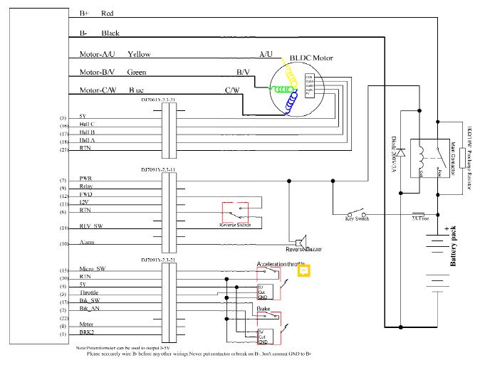
*Motor Temperature and controller temperature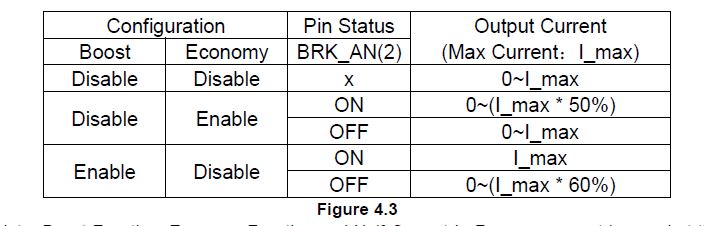 The motor has an internal thermistor, but i do not utilize it yet. Having a thermal output reading gives a reasonable indication of motor overloading. The controller at present actually allows for a 'boost' mode, There's a peculiar chart of the boost and economy modes, shown (right). This is a little confusing, there are two modes, "Economy" and "boost", the way this is intended to work is if boost mode is enabled in the controller, selecting it by toggling the BRK_AN(2) line high results in the maximum current being IMAX, when BRK_AN(2) is toggled low, the max current is 60% of IMAX. So, for this to work, the actual max current is set higher than expected, and you operate normally at 60% of that value. Its an interesting setup and could result in a neat 'I need 40% more please' mode. |
| *Reverse I havent wired in reverse yet, I'm a bit anxious about including reverse as at full power its an excellent way to capsize the craft. The controller supports 'half speed in reverse' which is actually impresivley useful in this application. I'm still anxious about enabling it, maybe some extra on board flotation is required in the back of the craft. |
| *Telemetry It would be great to grab telemetry of DC bus current, Phase current and motor RPM, along with motor temperature. Technically most of this information is sent out the 4 wire TTL uart port of the controller but its not presently documented in the manual. Kelly controls actually sells a blue tooth module that can connect to this along with an APK for android, but I have not yet tried it out / verified it supports data logging. One reason having motor rpm available would be to indicate what band the motor is operating in, is it hovering in the 2k rpm region at full current, or is it approaching 5k rpm? If I'm only hitting half of the target rpm at full current this would be a great indicator that the motor could benefit from a belt reduction, resulting in the motor operating at a higher rpm and transferring more power to the prop. |
| * Error Indication Right now the Kelly Controller outputs blink codes to indicate different error modes. At present those led indicators are located in a bit of a precarious location. Either being able to read these over the coms link, or, remot-ing the indicators would be useful for in-field debugging. |
| * Waterproof throttle One of the parts that i was a bit precarious about was the simple hall-throttle i had been using for throttle. They are notoriously bad when it comes to moisture. Oddly enough 'waterproof scooter throttle' isnt really an off the shelf item yet. I imagine the throttle out of a zero-electric motorcycle probably actually works in the rain but at the moment the concept of 'the throttle got wet and the boat decided to apply max power' is a bit of an issue. There are a few solutions, conformal coating spray applied tothe hall effect sensor, finding an actual waterproof throttle, or, simply using a set of well tested waterproof pushbuttons to simulate different throttle settings. possibly a sealed multi position switch and a forward pushbutton? It would be neat to actually have a bell call lever for throttle set and some type of dead mans switch to prevent 'runaway boat' syndrome. |
| * A shroud for the mechanicals Finally, adding a shroud around the top to clean up the look of the outboard would be great for also hiding the cabling and any exposed rotating parts. It would be pretty excellent to go for some ~60's era spaceman-spiff look, |
| * An Emergency Stop The correct wiring for this motor controller uses a contactor to enable / disable the drive, which, for all purposes is a good idea. During this test i wired the battery bus directly to the input for simplicity but having a contactor and a pre-charge is a really good idea going forward. |
| * Detecting leakage current One interesting mechanism to limit and detect to the hazards of medium voltages in a watercraft is to having indication for hull to battery leakage. I imagine if there's any voltage present between hull and Batt +, its a good idea to stop and determine why or what is leaking. This may be a DC leakage path, or high frequency AC coupled through to the hull. I hesitate to use a ground fault indicator as, well, this is a DC low voltage application but it may be a good idea to investigate what is available in that realm. I imagine there's 48V DC widgets on swanky yachts, or sail craft, so there may be associated safety hardware. Finally using a large system fuse, with an indicator would be a great last step forward, having a zener-resistor led setup to display 'your fuse is blown' would be quite great. DC circuit breakers at that power level are a bit expensive or huge, most reasonable sized ones end around 50V, at 50A DC. |
| Solid part files |
|
(There's
other
photos in the photo gallery)
Concluding Remarks:- Silly watercraft are incredibly fun. There's something excellent about a quiet electric outboard on a small watercraft zipping along. Tackling the hazards and challenges of electric propulsion in a small conductive craft is a fun challenge, but should only be undertaken carefully and with quite a bit of caution. Its a good idea to use safety hardware and a colleague in a chase vehicle when testing out experimental watercraft
- Bring a paddle if your testing an experimental boat.
- Water is incredibly viscous and the amount of energy
required to move a flat bottomed boat is increasingly
impressive. Velocity appears to go by the cube of
energy, which nominally makes sense traveling at 60mph on a
reasonable sized craft requires in excess of 100kw. The only
way to go faster with less is to limit the actual viscous
contact area. For a flat-bottomed boat thats, well not
trivial. Some pontoon craft get around this issue by reducing
their water footprint to only the submerged section of the
pontoons themselves.
If you have questions or comments, ask below or send over an email.
| Comments: |
|
HTML Comment Box
is loading comments...
|
Stay safe when working with electrons in aqueous environments. Also wear sunscreen, I'm not responsible for your newly acquired farmers tan : ]
Dane.Kouttron
Rensselaer Polytechnic
Institute
Electrical & Electrical
Power
631.978.1650
