Dane.Kouttron
[6.2.12] 3D Print-ARM [aka: My Bots Bigger Than Yours]
| What?
An ancient, monstrous SCARA robot arm, open sourced servo-motor drives, and an ABS extrusion print-head with Linux-CNC gluing everything together. |
 |
|
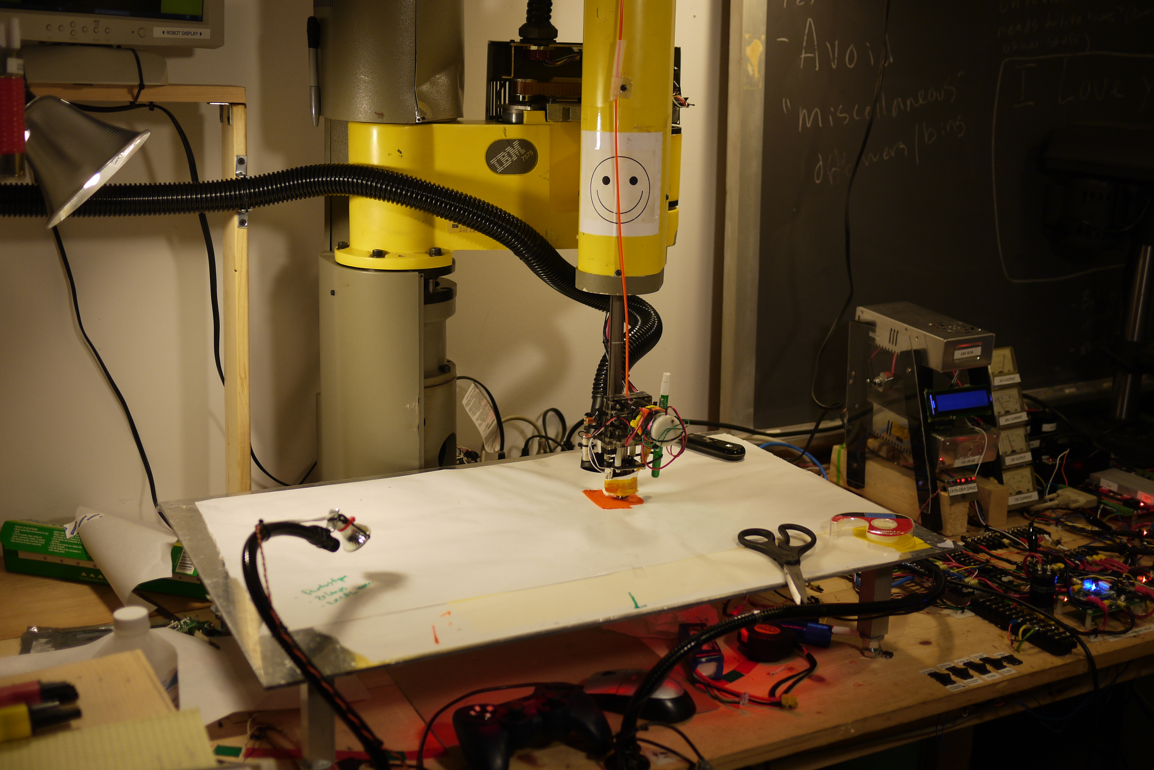
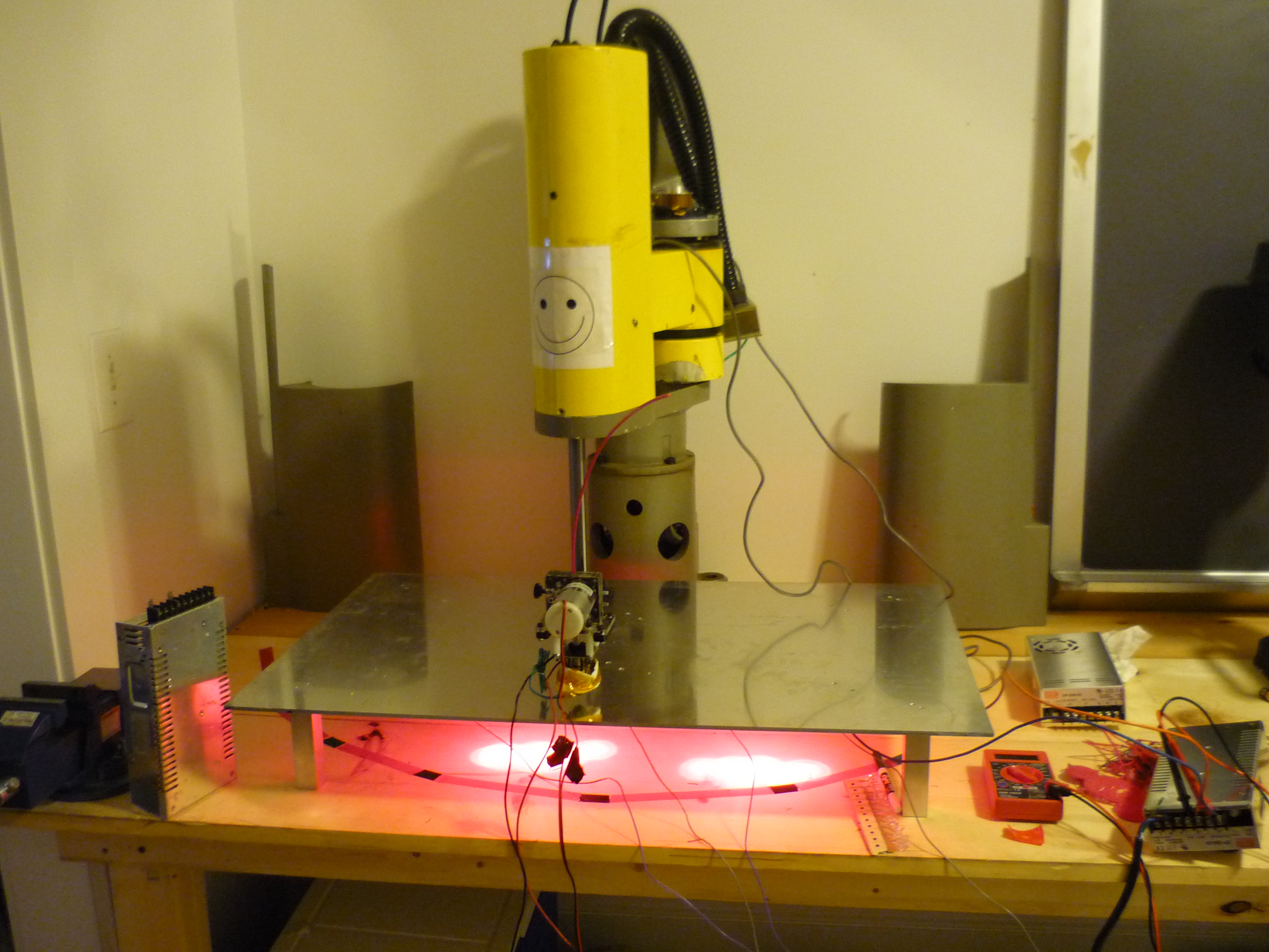
| This project documents the re-purposing of a 'rescued' 1980's IBM 7575 SCARA Robot Arm, into a functional 3D ABS printer. The project features some motor upgrades [listed earlier], documentation of encoder positioned motor control feedback theory, the interminglings of EMC2 [Linux CNC], heated workspace construction and a step by step overview of transitioning from 3D stl model to 3D g-coded structure. The huge reach of the 7575, allows for printing large objects, (roughly ~25"x12"x6.5" maximum). Some of these prints are shown below. |
| What? |
Mechanicals | System Layout |
Motor Controls | Extruder | Linux CNC Configuration | Thermals | Skeinforge | Prints | Image Directory |
| Video of Operation | Vid |
| Starting
at the end. The following is a demo video of the IBM 7575 robot-arm-abs-printer tackling some earlier medium sized prints. Note this is running from the developed hardware detailed below, not the stock controls hardware. All hardware to computer interfacing is done over the DB25 parallel port. Check out the video in HD: Link |
Breathing Life into the Beast
| The Robot: | ||
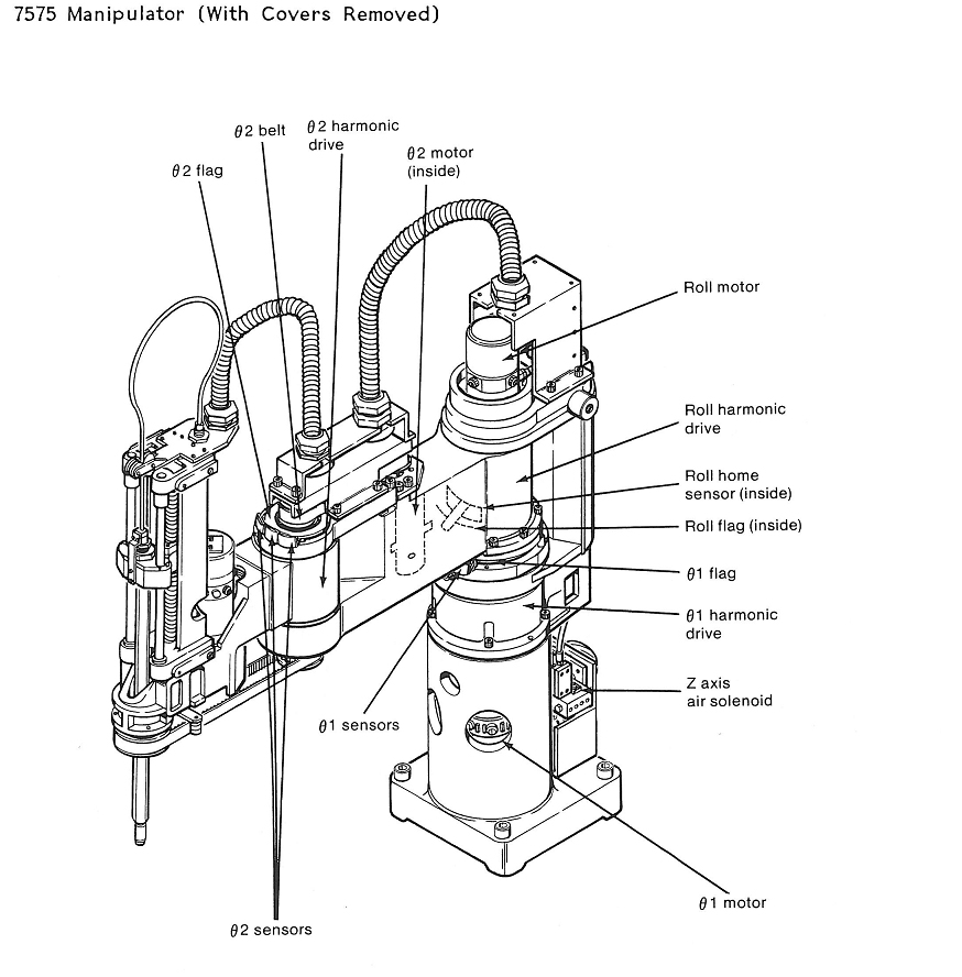
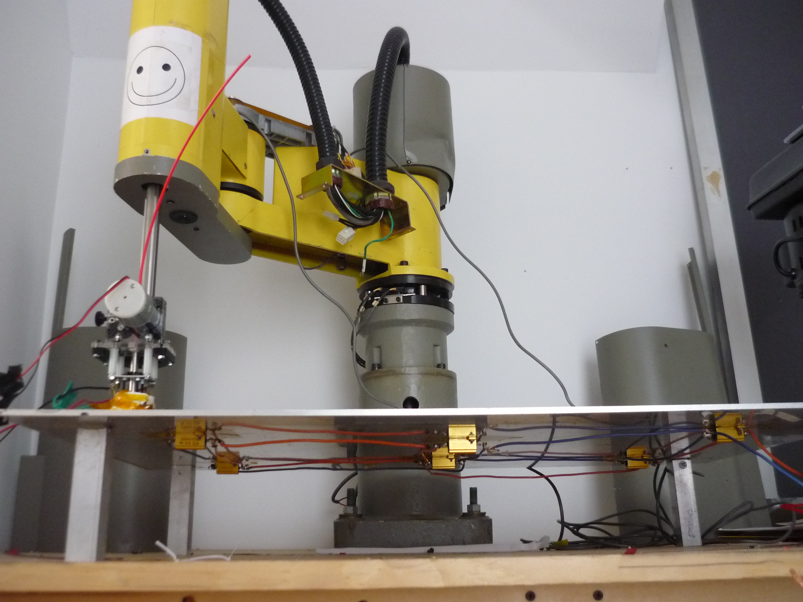
| The
robotic arm this project is built around was scavenged from a lab
clean out. Unfortunately, the motor drives, servo amplifiers and control hardware was nowhere to be found, so suitable replacements needed to be sourced/designed to drive each axis. The arm initially ran from 4 DC Servo motors with high-precision encoders. Each motor would tie into a corresponding PID feedback controller to allow for precision positioning. The DC motor provided the high-torque low RPM drive, and the precision encoder provided precision position feedback. Presently, a number of 3d printers on the DIY front, rely on feedback-less stepper motor assemblies. Using high-power steppers, sized much greater than the application's torque requirements, in conjunction with a driver that maintains a holding torque throughout operation, the printers can skip feedback systems and still preform remarkably well. For this project i opted for a mix of the two. |
 |
 |
| A
large wooden workspace was built to support the ~190lb machine, care
was taken to ensure the work surface was stable yet easy to
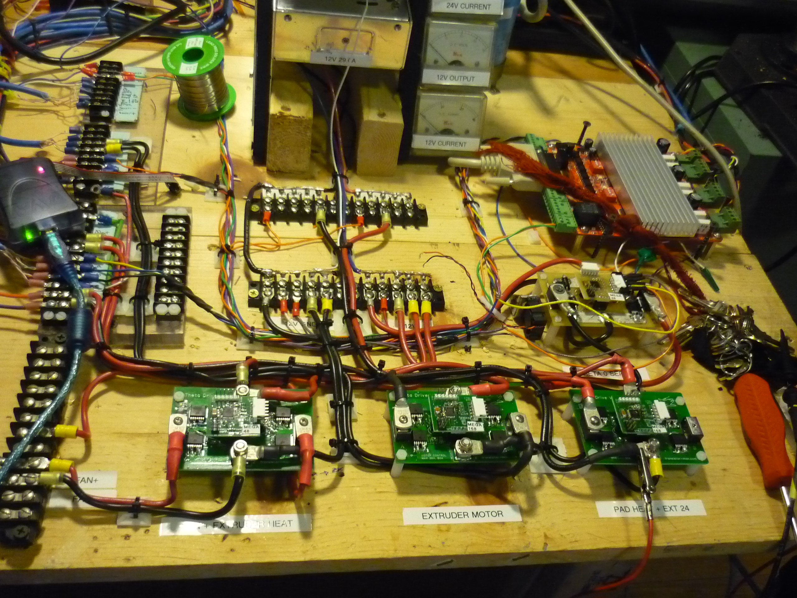
modify. The control
electronics grew in complexity and sprawled across the right side of
the table. Shown is 2 DC power supplies to supply the 14 and 26v rails,
a few screw-down interfaces, 4 theta v2 drivers, and a stepper motor
drive assembly [Datasheet link] To get this working i took the 'iterative' approach, started with basic motor controls, worked through each issue, and incrementally tuned better accuracy, tighter feedback loops, and increased functionality. |
 |
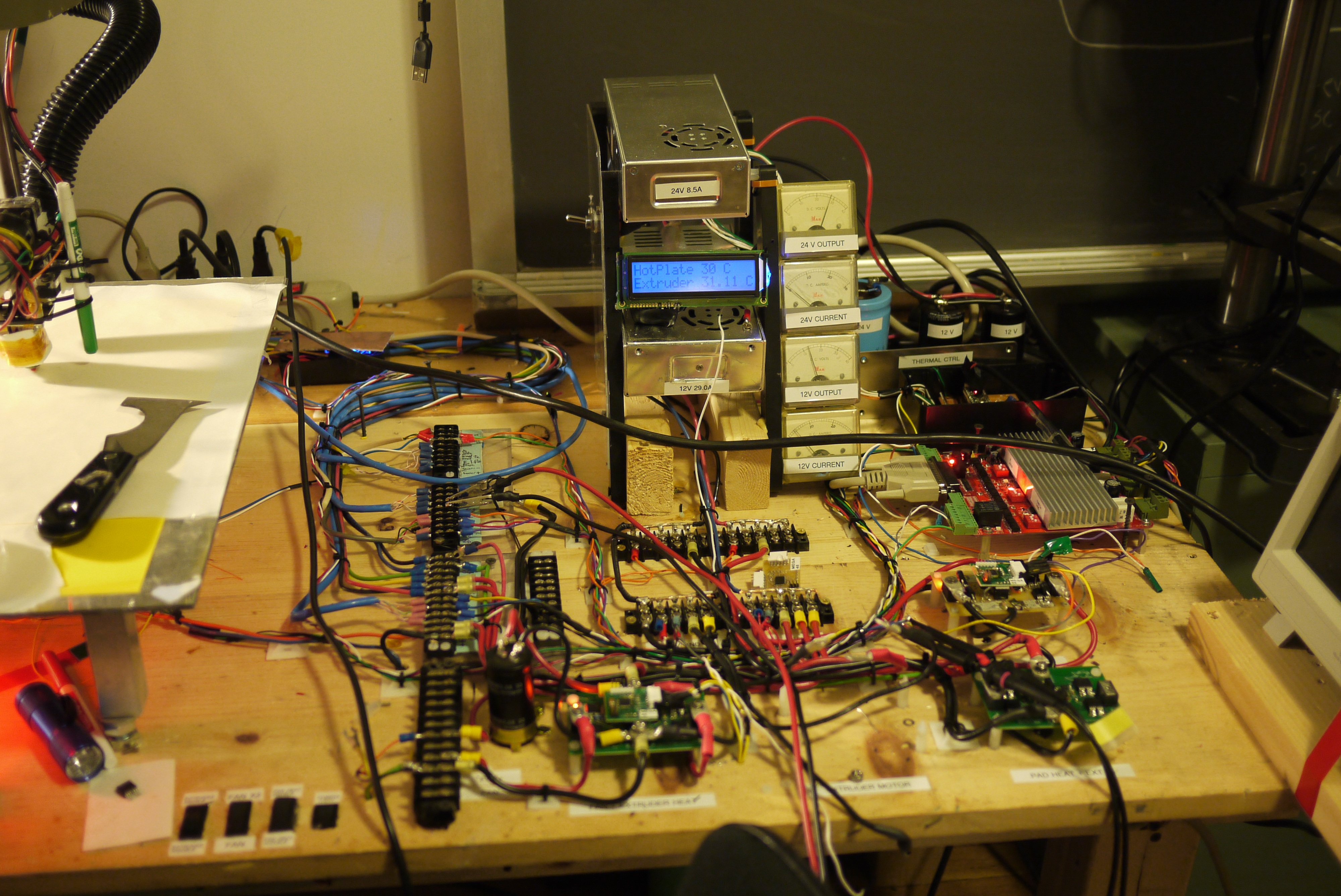 |
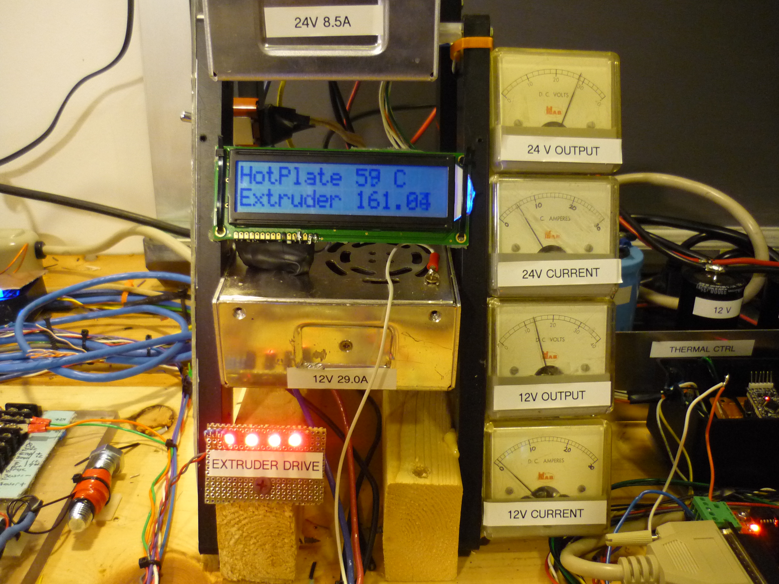
| Heated
Build Platform The heated build platform consists of a 1/8th " aluminum plate, donated by a colleague, and six 25W power resistors. Teflon coated wire (rated for 150C) was used for wiring the resistors in series. The heated build platform is fed from a 24v 8.6A supply, tuned to 26V. The heater assembly dissipates roughly 200 watts. Two linear temperature measurement probes, each using a separate Microchip MCP9700 (link) feed temperature back to the main Temperature/Heater controller. After a 6 minute warm up time, the build platform reaches 65 Celsius, near the stress relaxation point of the ABS plastic used in the printer. Its also, fortunately, right below the 'argh, i singed my hand' temperature threshold. |
 |
 |
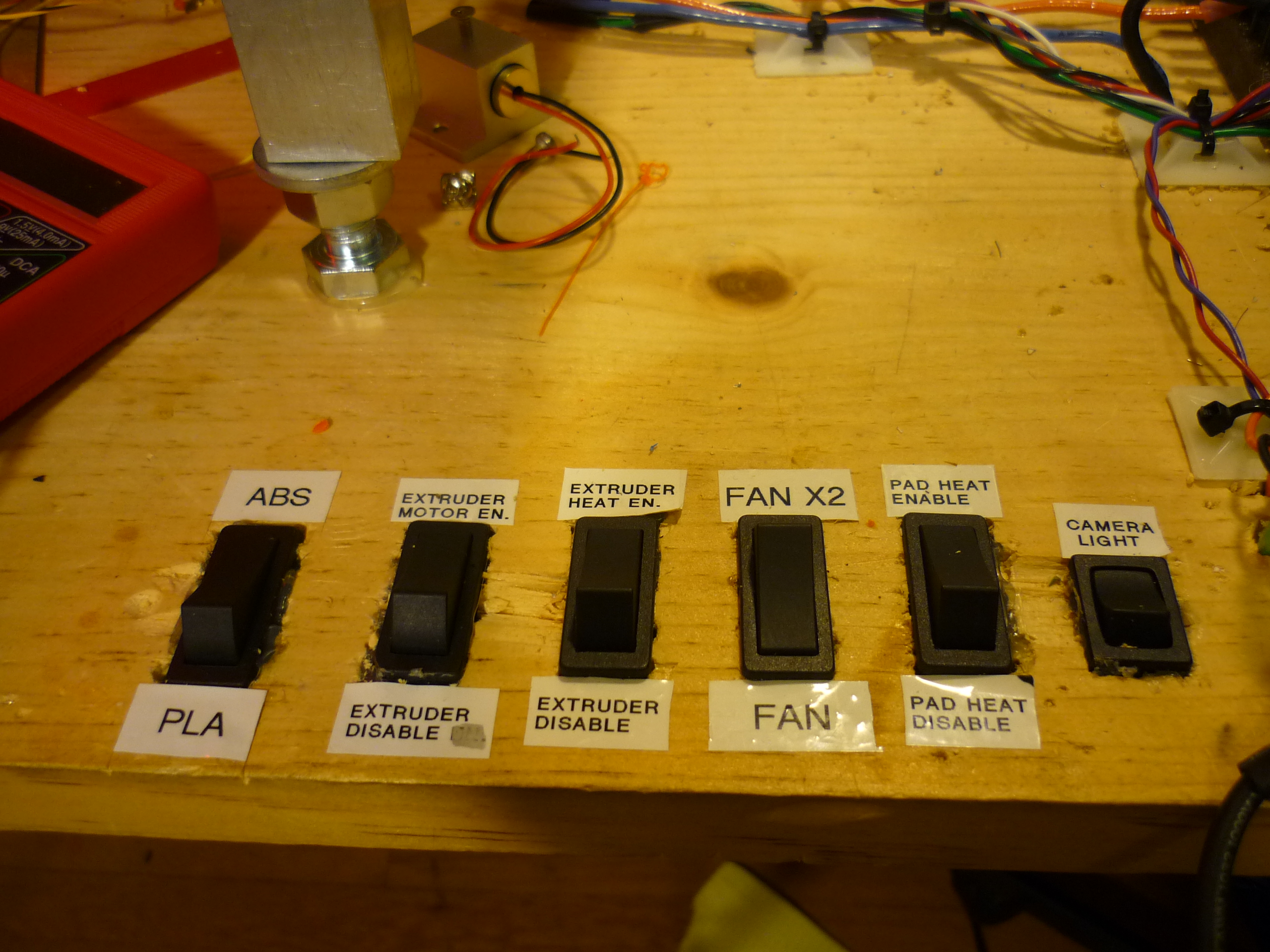
| Pile
of Switches and some Dials I used a number of 2 position slider switches for the various settings on the robot, and also to disable some functions when code went awry.
|
 |
 |
System Layout
| Configuration: | |
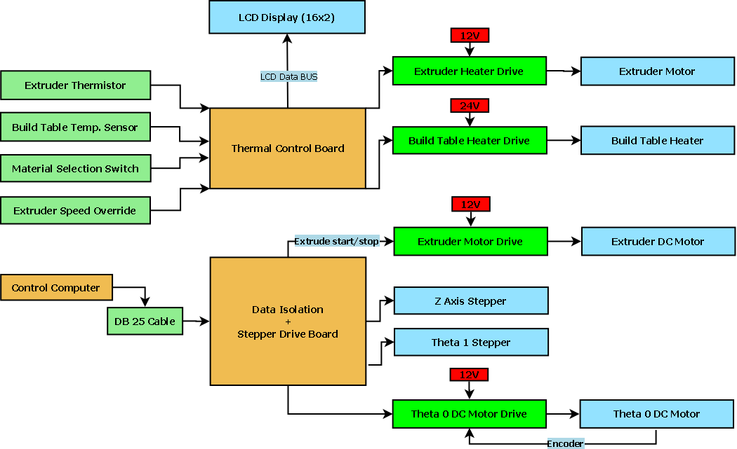
My goal for the robot controls was to keep things as simple (and cheap) as possible. To do this, i made use of Linux cnc's great tye-in with real-time parallel port data output. The system topology can be broken into four main components.
|
 |
| From the sponsors: |
MOTOR CONTROLS
| How | Image/ Media | Image / Media |
| For the main axis, a giant DC
motor with encoder is used. Opting for replacement with a stepper
proved difficult and potentially very expensive. To drive this motor i
developed a high-current H-Bridge that could use encoder data to
position the motor. To drive a DC-Brushed motor with encoder in a
similar fashion as a stepper, a relatively high-speed PID loop, taking
in feedback from an encoder, is used. Whats PID you say? Continue reading! |
 |
 |
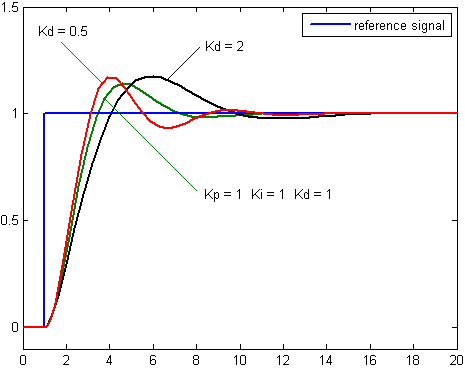
| Proportional
Integral Derivative PID is a feedback-control toplogy for closed-loop control of a system. Open loop control is simple, imagine you want to control a DC brush motor, and you want it to turn 1 revolution. To do this, you could pulse the power to the motor momentairally and assume the loading on the motor is always constant. Unfortunatley, loading, wear, and other factors make this method very prone to error. Closed-loop control takes that goal of rotating the motor 1 revolution, and provides a feedback mechanism to observe the completion of that goal. The feedback mechanism could be as simple as a switch that senses when that one revolution has occured, or as complex as a high-speed multi-phase encoder. The values for P, I, and D effect the system's response to changes. PID consists of 3 terms, weighted together to achive the initial 'goal' its set to achieve. Proportional (outputs value proportional to the current error value), Integral (accumulated offset), and Derivative (rate of change control). The theta0V2 controller preforms a high-speed PID loop taking a command (increase desired position), and attempting to push the motor to that position, using the encoder to verify it achieved that 'goal'. An example of the over/ undershoot with different constants is shown far right. |
 [borrowed from wikipedia]
|
 |
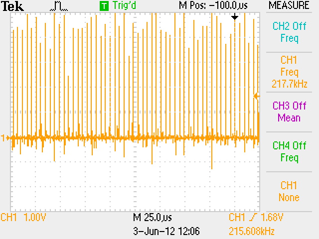
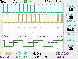
| Determining
Max Operating Trajectory / Speed Next I needed to see the bandwidth of the PID loop. A GPIO tied to an led was twitched each operating cycle. From the oscilloscope (right), we can see that the operating scan rate of the PID loop is roughly 217kHz. As the 'Step' input is tied to an edge-triggered interrupt, the 200kHz is the maximum rate the hardware can respond to the encoder inputs during the increment event. Far right is a view of the encoder inputs (green / purple) versus the commutating frequency of the motor (orange / blue). |
 |
 |
Extruder
| Upgrading the Hot End of the printer | ||
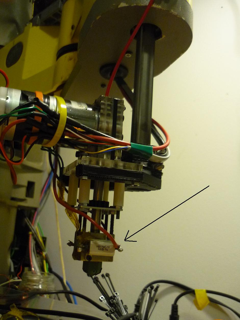
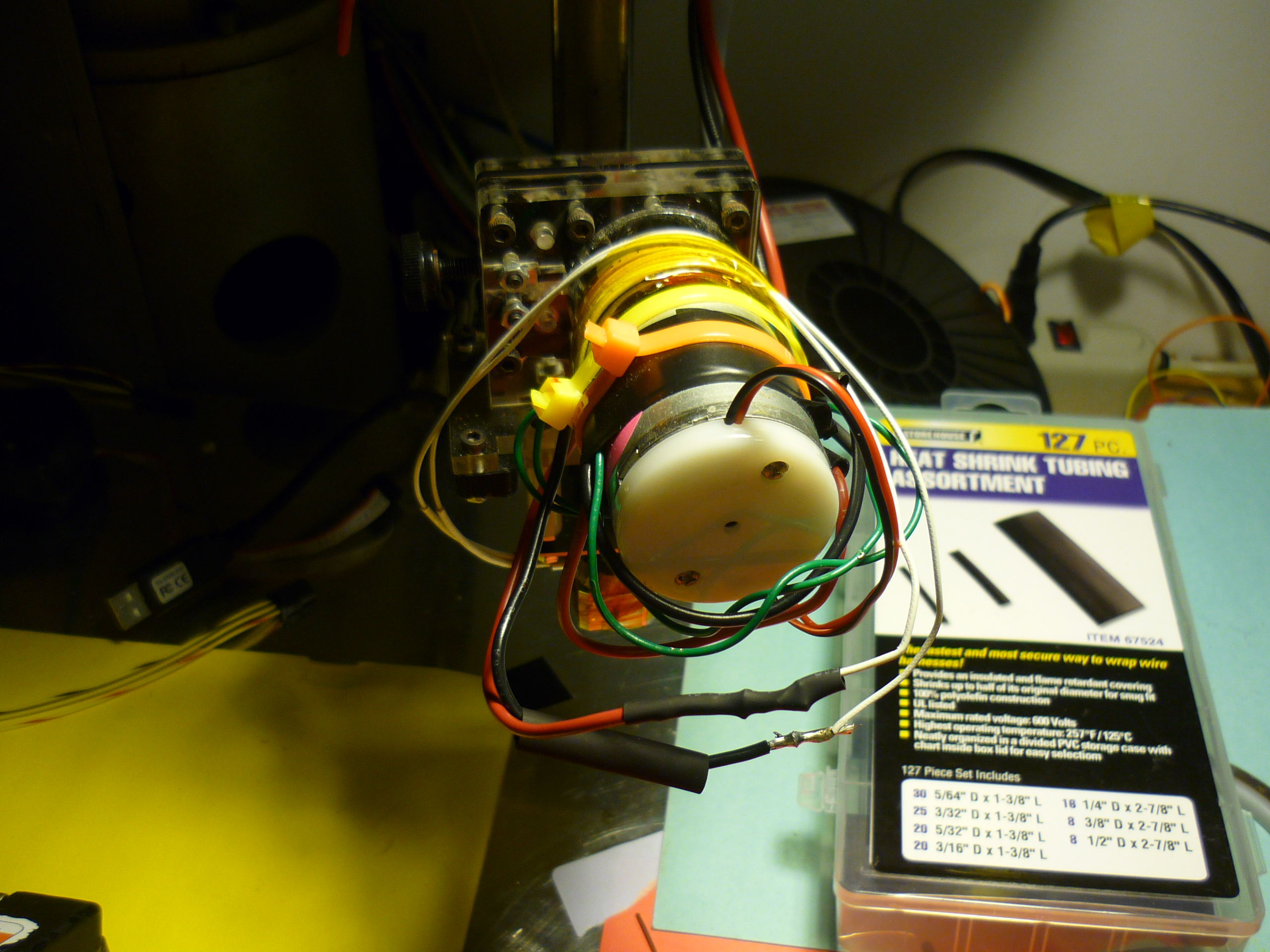
| Initially
i had been using the '2x resistor-block heater' extruder head,
identical to one used on a makerbot-mk5, however after some frequent
burn-outs, [literally the resistor insides coming out of the extruded
metal shell], i upgraded to the cartridge-style heater shown below. The root of the resistor semi-frequent meltdown came down to component rating. That resistor was rated at 10W..... when operated at 25C, at 160C, it was rated to ~2 watts. I was pushing ~11W into the resistor at 160C, and after a few hours, the part failed. A number of other makerbot folks ran into this issue [Link]. A NTC thermistor is kapton-taped to the heater block and fed through shielded cabling to the thermal controller. I plotted some comparisons with a reference linear temperature part and used the data to create a linearization formula, listed below |
 |
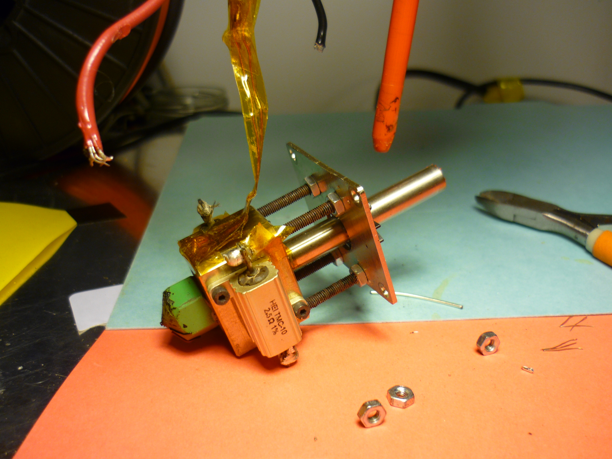 |
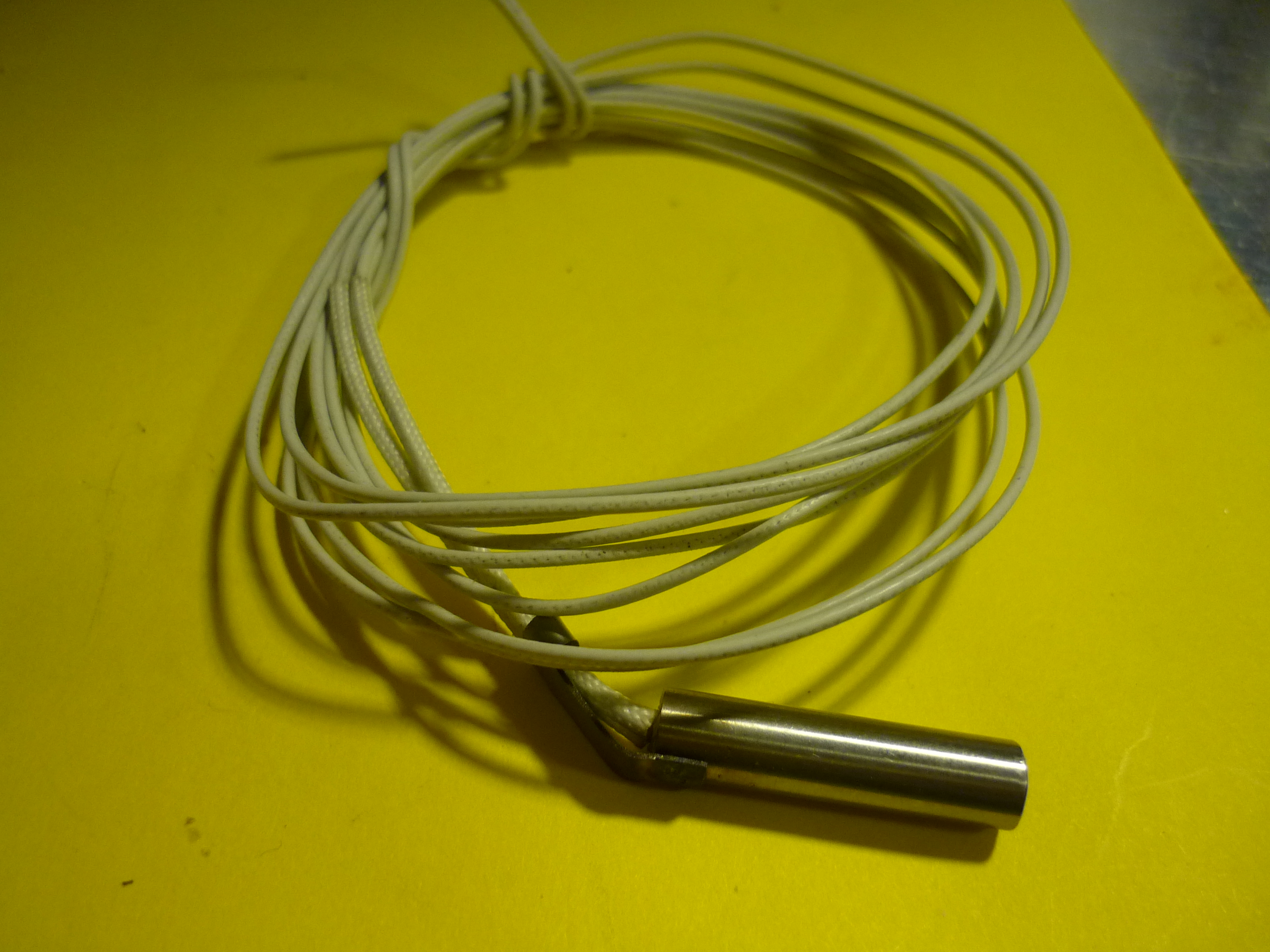
| Cartridge Heater + Teflon wire and milled & tapped new heater-block-head. The heater [Link] is held in place with a small tapped hole and screw. The wire feeding power to the cartridge heater is Teflon/fiberglass coated and heat resistant. | 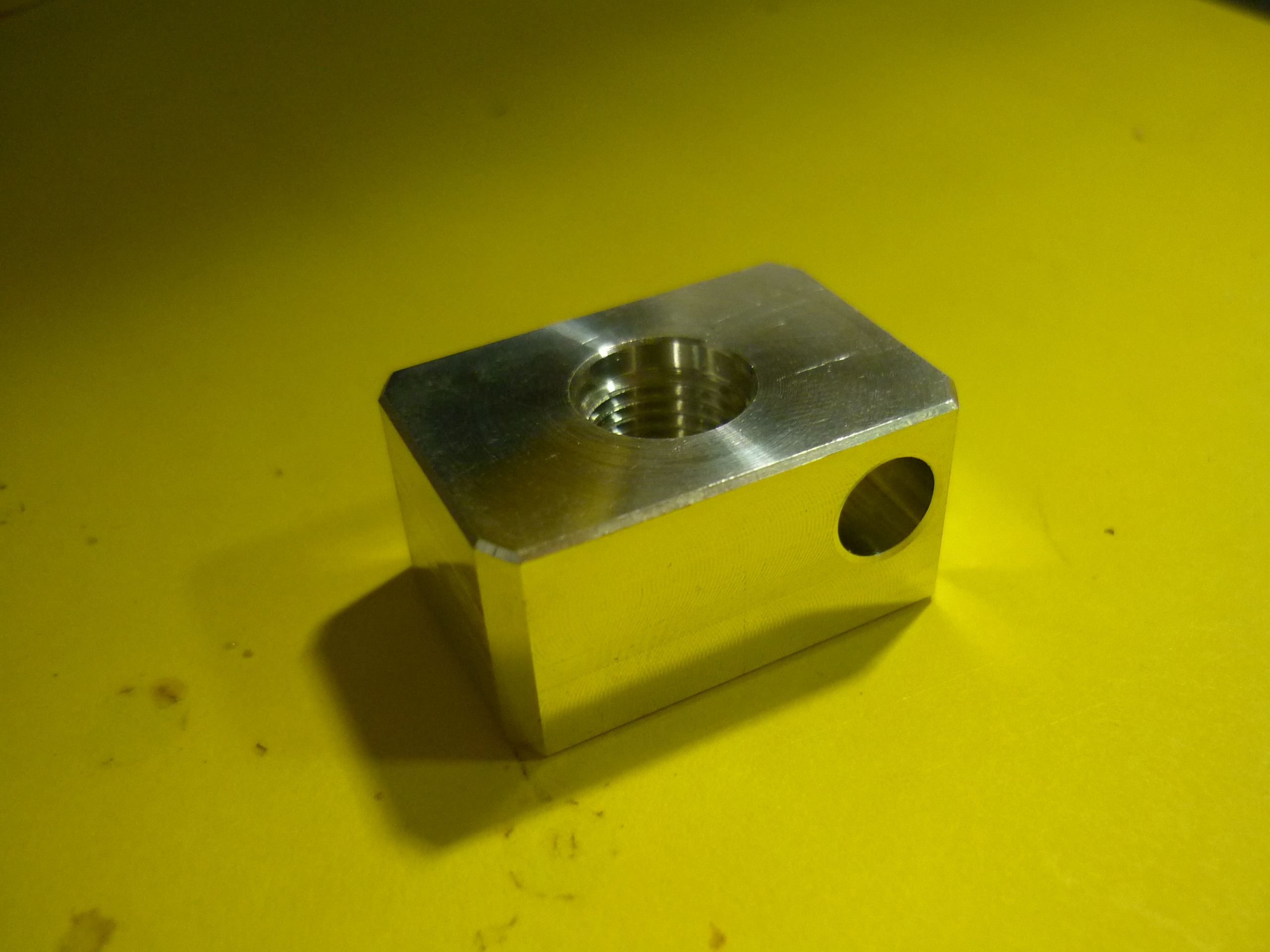 |
 |
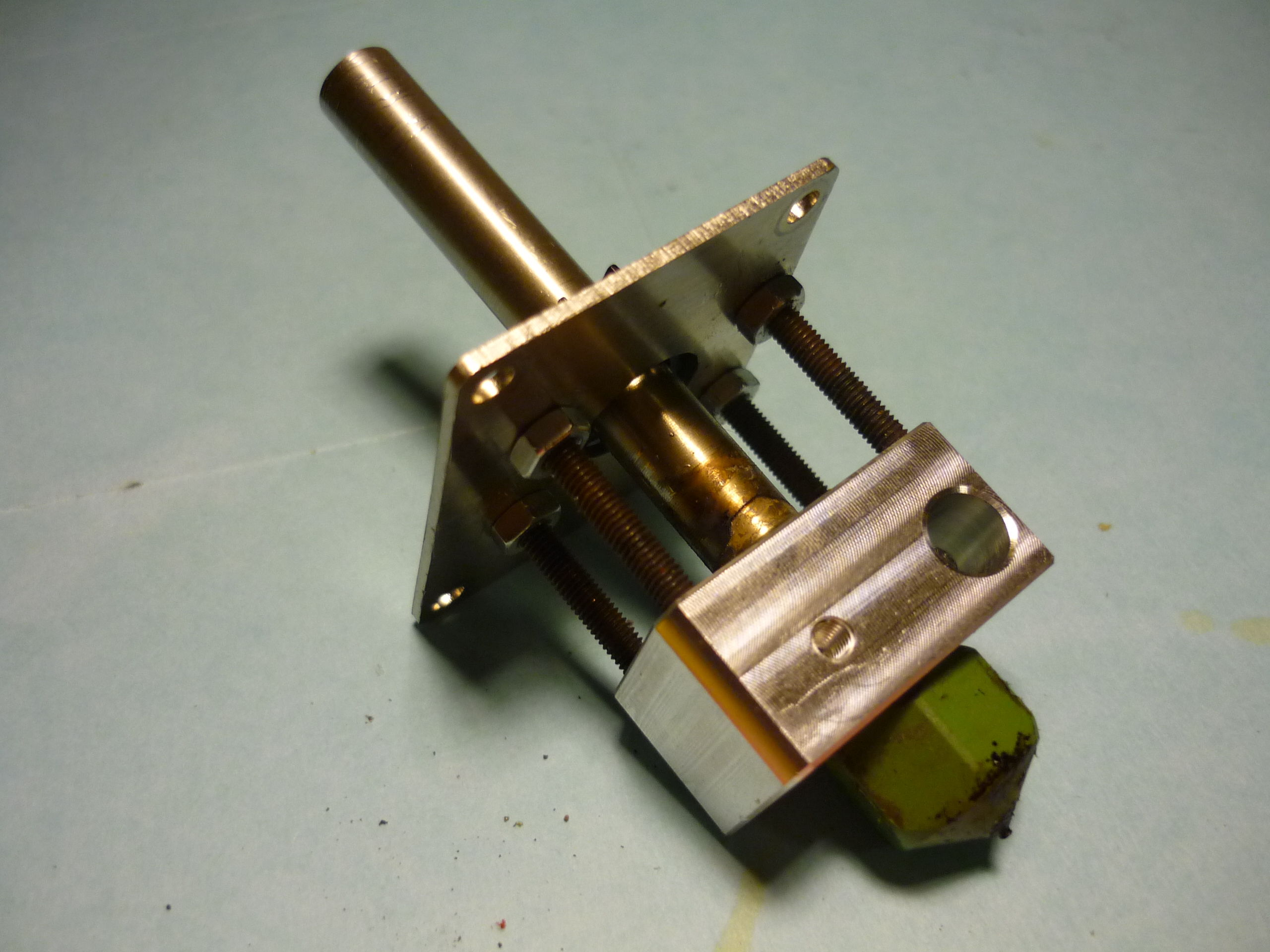
| Putting
it all together... The extrusion head with new cartridge heater mount. This is re-connected to the DC extruder motor assembly. I kapton-taped the thermistor to the aluminum block assembly for temperature measurement. |
 |
 |
Ventilation
| Ventilation System: | ||
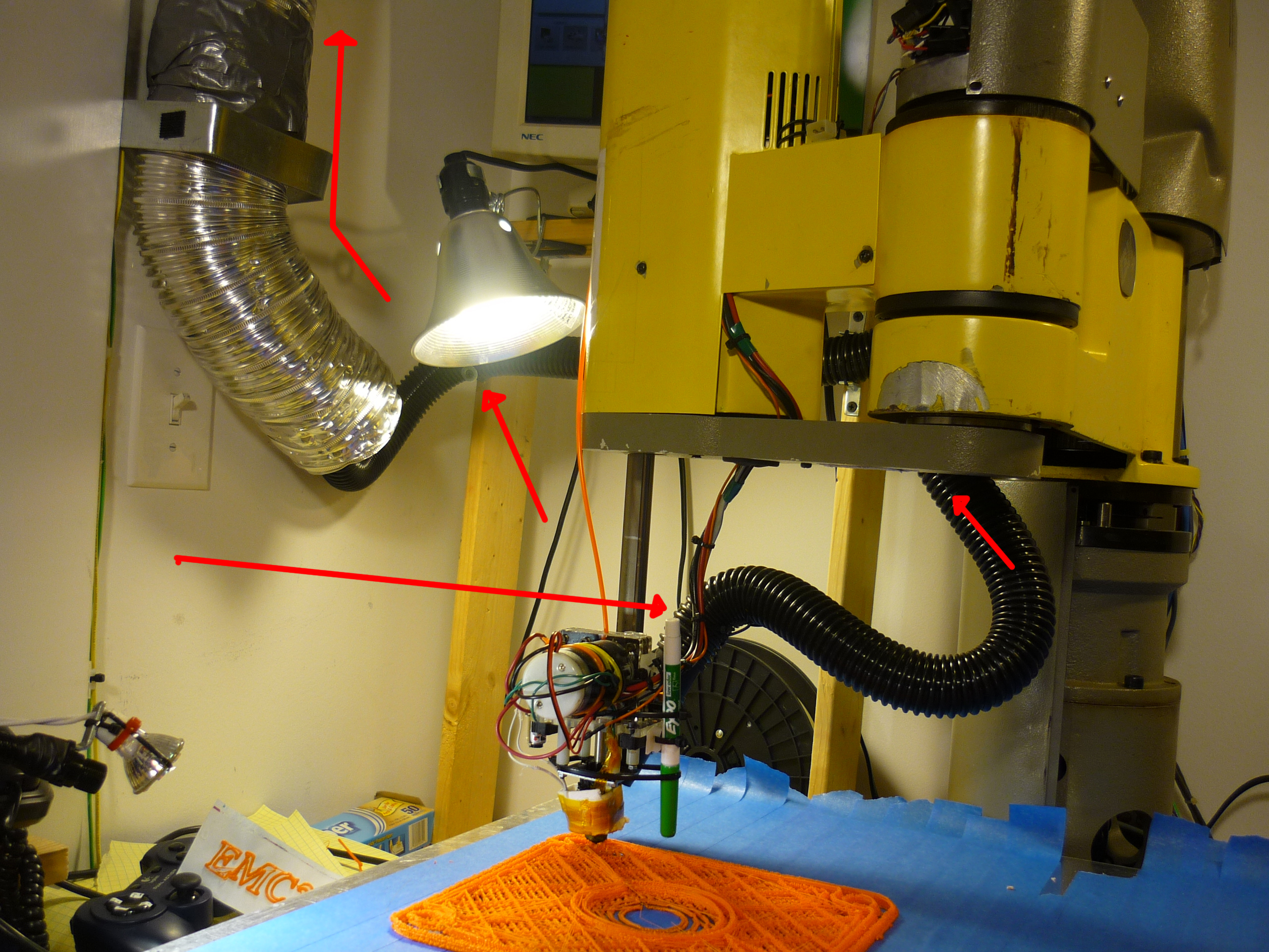
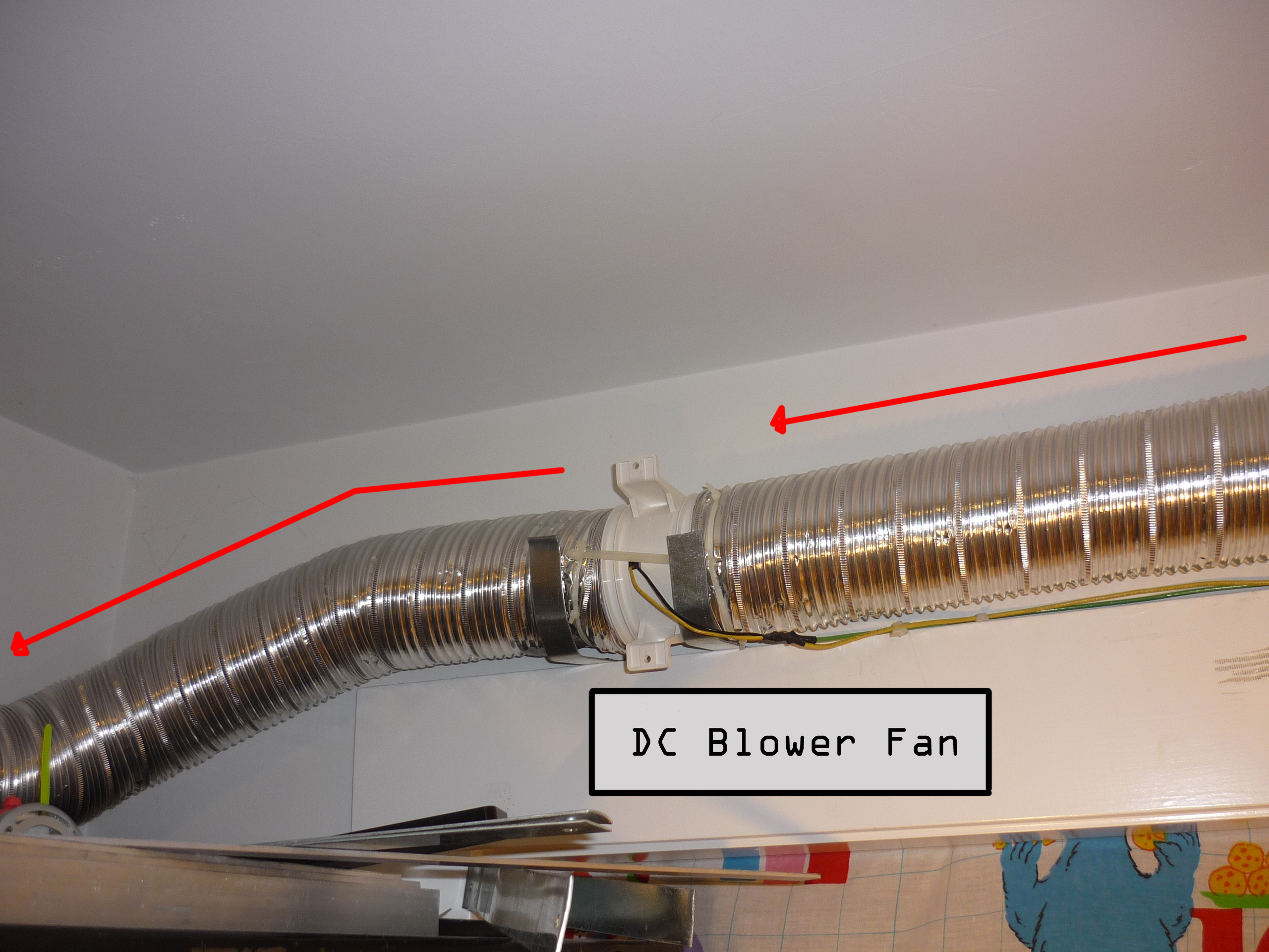
| I built a fume
extraction system, using 4" ducting and a 12v DC blower fan. The
ducting [Link]
was the solid type (not ultra flexible / flopsy), and was able to hold
up its own mass. It adds a nice 'industrial' feel to the setup. Red
arrows (shown right) indicate the direction of airflow. The shorter
black tubing [link] connected the extrusion head
to the large 4" ducting The DC blower [Link] was a bit pricier than i was hoping, but also worked well. 'Quiet' was a relative term, and i ended up de-rating the operating voltage to 9v to mitigate the noisiness at 12v. For those out there who'd like to use this specific blower, at 9v it pulled 2.2A, at 12v it pulls ~3.14A. I first ran across these type of in-line fans from a friend, [Shane], on his, um, 'alternative' propulsion scooter [Link] |
 |
 |
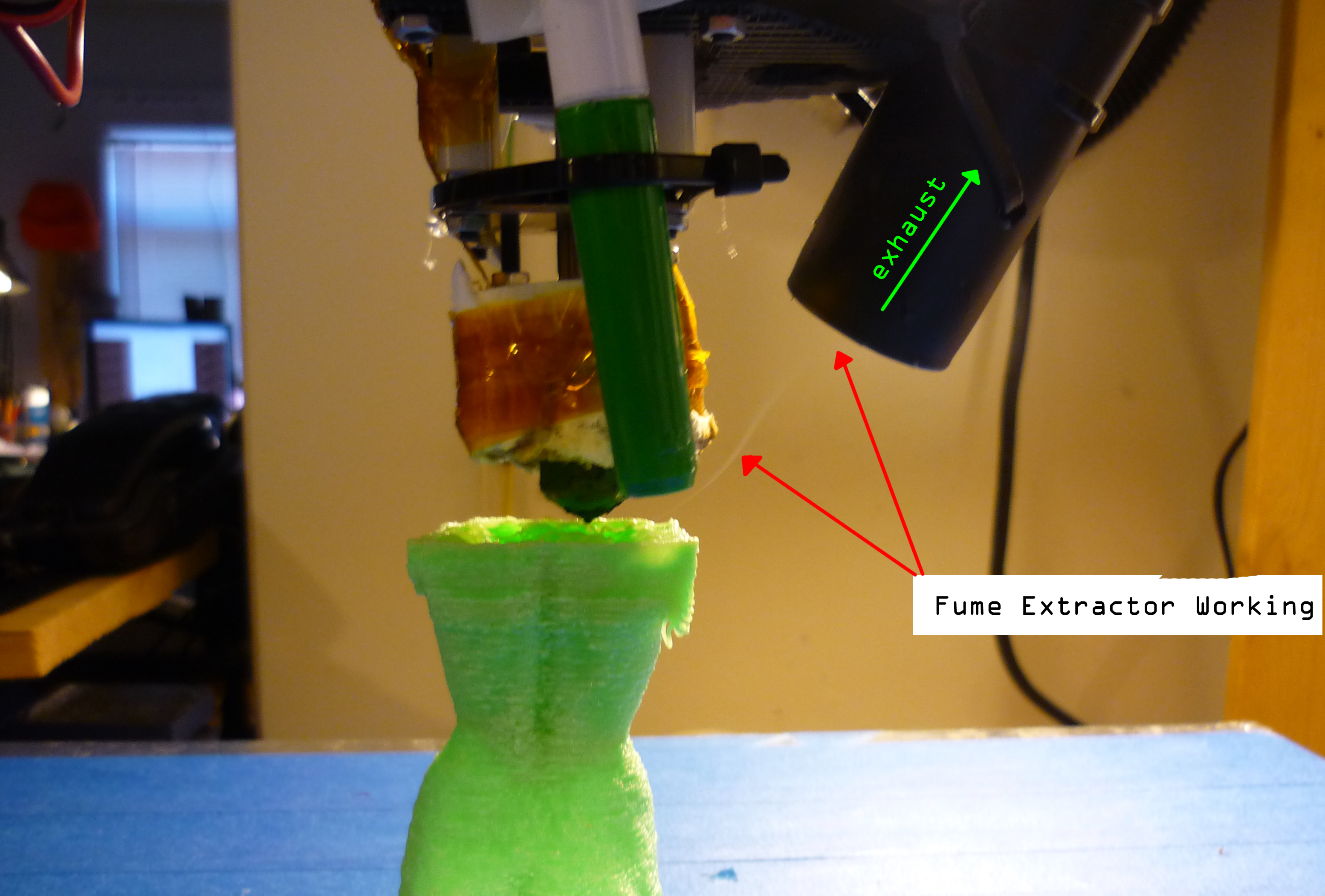
| Some
quick proof of functionality Why use such a large ducted fan? 200cfm just for a fume-hood? Because of the extended length of the duct i chose to overisze it. It is way easier to throttle down a large dc brush blower than constantly over-drive a smaller one. |
 |
 |
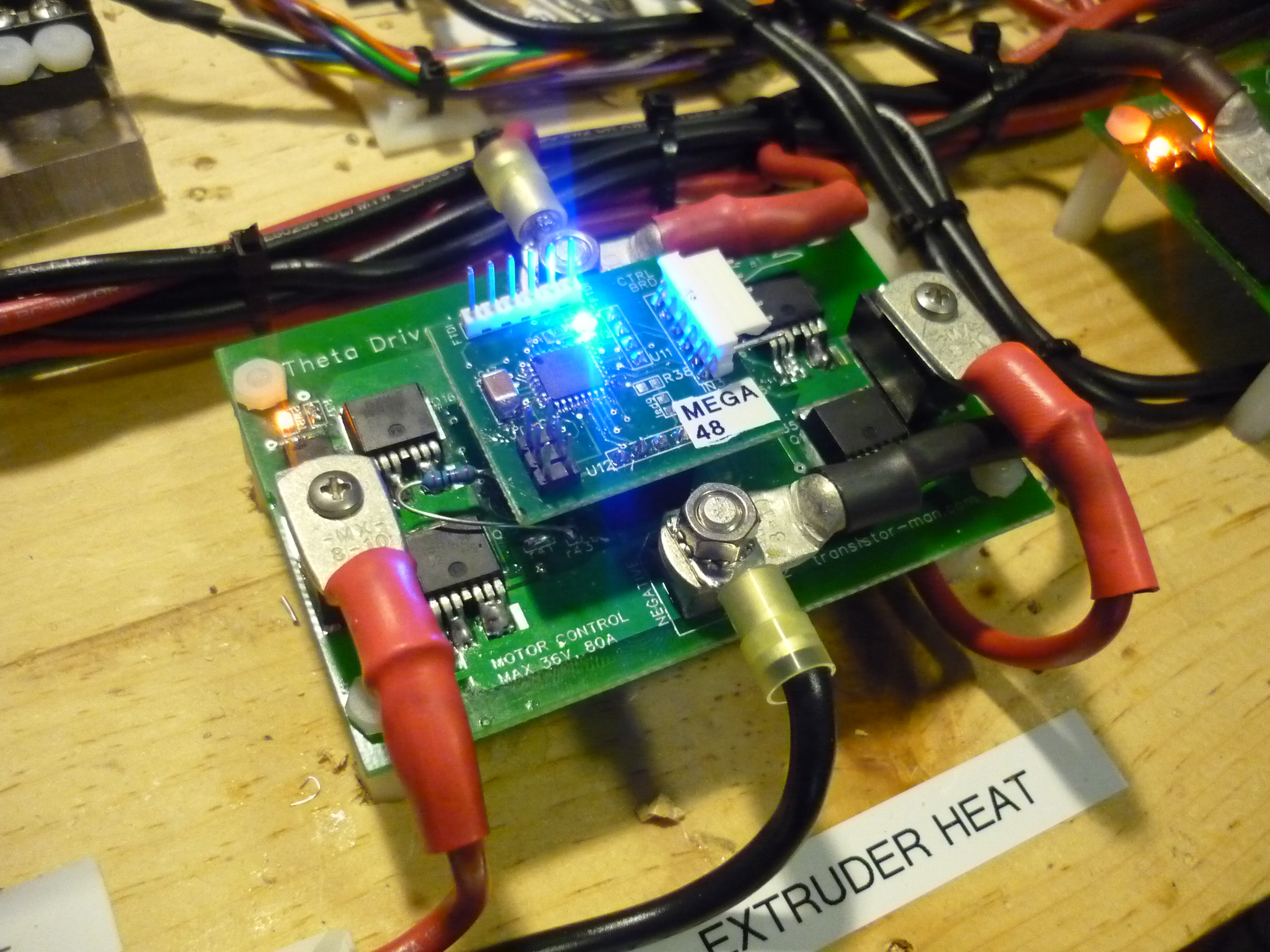
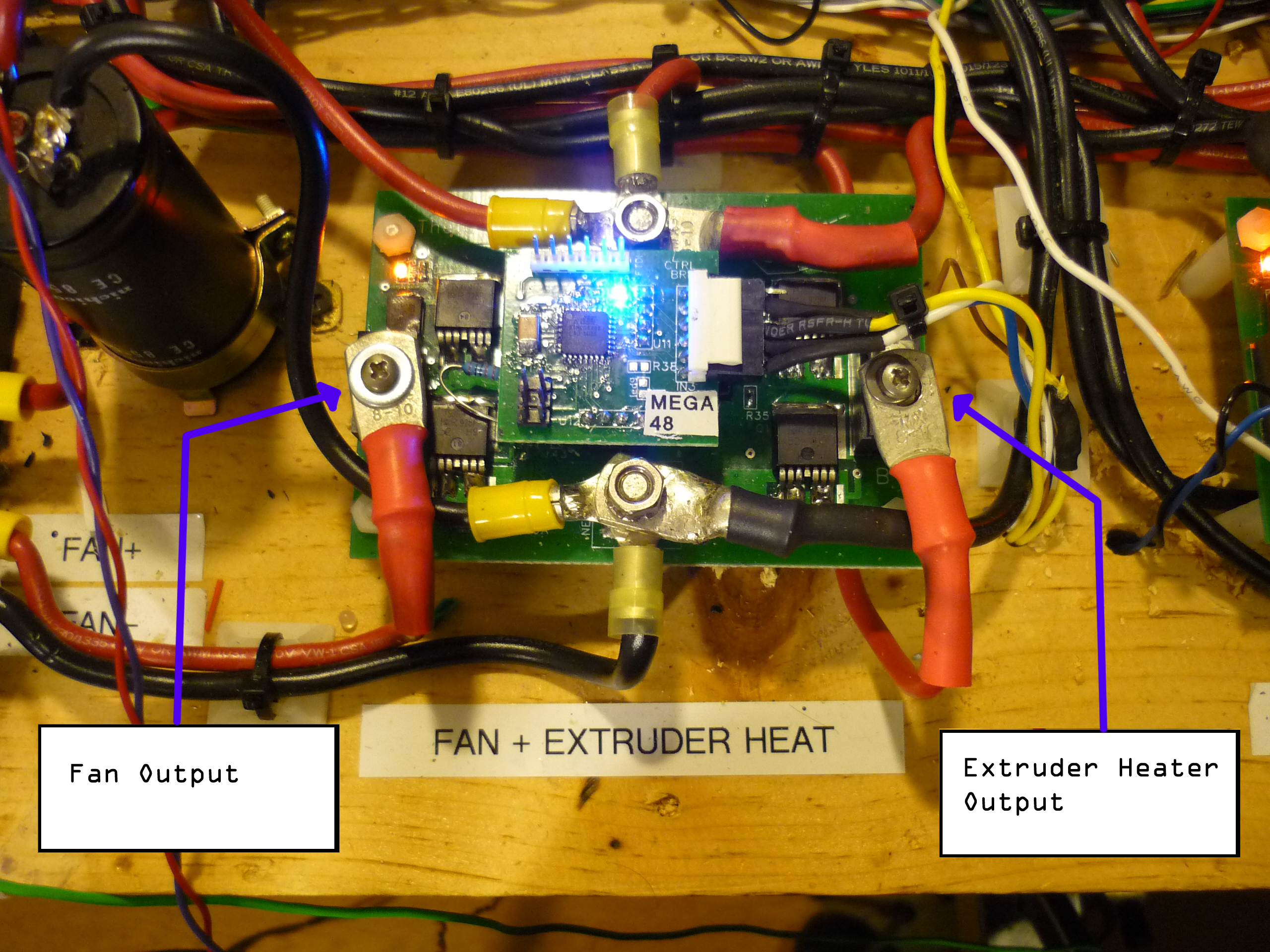
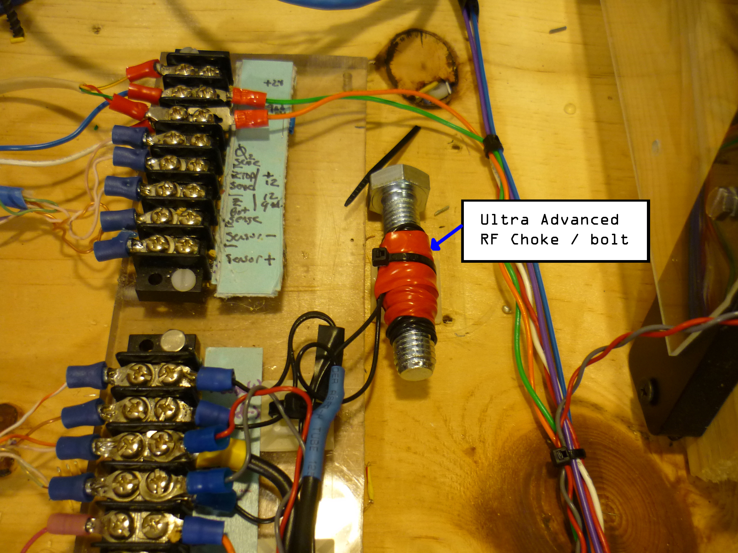
| Noise I ran the DC brush motor from one side of a Theta0V2 motor controller, switching at ~30kHz. As the Exhaust fan only needed to blow in 1 direction, i was able to use half of the H-Bridge for the exhaust fan, and the other half for driving the extruder heater. The Acoustic noise wasn't the most of my concerns, as the motor was located ~10' away from the robot, i ran 12' of cabling to power it. As it turned out, switching 3A at 30kHz on a long wire made a wonderful antenna, generating a boatload of EMI. Enough EMI to cause the Theta 0 encoders to miss steps on occasion. I rectified the problem by adding a very advanced 'RF choke', shown far right. |
 |
 |
LINUX CNC
| How to: | Image/ Media |
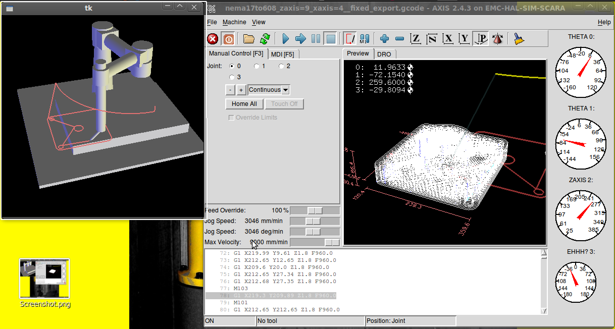
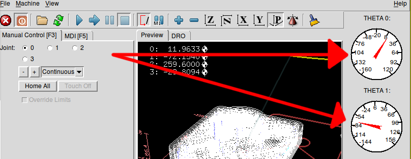
| INI and
HAL files, running the show In Linux CNC, 2 files do all the configuration hard-work. INI and HAL. The INI file describes each axis's type, maximum and minimum speed, and homing locations, while the HAL file describes the hardware interface layer between Linux cnc and the external hardware. The Linux cnc package has some excellent, dense documentation on both the INI [link] and HAL [link] files. Shown right is the user interface, consisting of a 3d model displayed by tk (far left), and the gcode model with trace paths shown. The Axis data is displayed on the far right, and detailed below in the scara.xml section. |
 |
| INI
File Details: Notes from the INI File Setup: This ini file was based on a mix of the sample INI file for KUKA machines and a basic INI output from stepgen-config. Two threads control the machine, a SERVO thread which is a slower global positioning thread and a BASE thread which provides the higher speed pwm/pulse generation for STEP/DIRECTION output commands A separate image is set to display on startup [robot.gif] Added in Image detection on import, an awesome feature that loads 'image-to-gcode' when a greyscale image with png, gif, or jpg extension is loaded. PROGRAM_EXTENSION
= .png,.gif,.jpg Grayscale Depth Image
The Traj section
sets global max velocities, max accelerationspng = image-to-gcode gif = image-to-gcode jpg = image-to-gcode The Axes section sets each axis's parameters, input scales and setup for homing sequences. Note that AXIS 0 and AXIS 1 are polar axes, while AXIS 2 is the linear Z axis for up/down |
|
| Kinematics The robots forward kinematics are defined using the following, referenced to figure 1 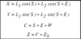 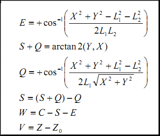 The full kinematic model is
defined, with some modifications, in this file [Link].
Note the kinematic file is complied before executing the robots
actions, making modifications without compiling will have no effect
This is A HECKUVA LOT MORE COMPLEX than cartesian systems used in a makerbot style 3dprinter. |
Forward
Kinematic Axis reference Inverse Kinematic position reference 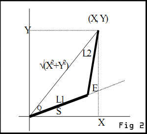 |
| HAL
File Details: This is the HAL file that links all the system signals to the kinematic model and then outbound o the parallel port aka 'parport.0' Mixing stepgen and scara kinematics was a difficult exercise, there are a number of commented-out sections from the debug process. I ended up generating a servo-thread for each axis parameter (0-8) and then piped the output to the parallel port (parport, 0X378). After stepgen was generating step-direction data, that is linked to the actual positions (J0pos, etc). This acts as the feedback path keeping the robot actual positions bounded by the planned positions. A few functions were inverted in output state, however a simple setp
parport.0.pin-03-out-invert 1
Inverted the
state before it hit the hardware outputFault inputs and limit switches were generated next to prevent out-of-bounds positioning and prevent the robot from running into the wall (again) Lastly, each axis of the robot commanded positions were fed back into the scaragui net j0 axis.0.joint-pos-fb
scaragui.joint0
|
|
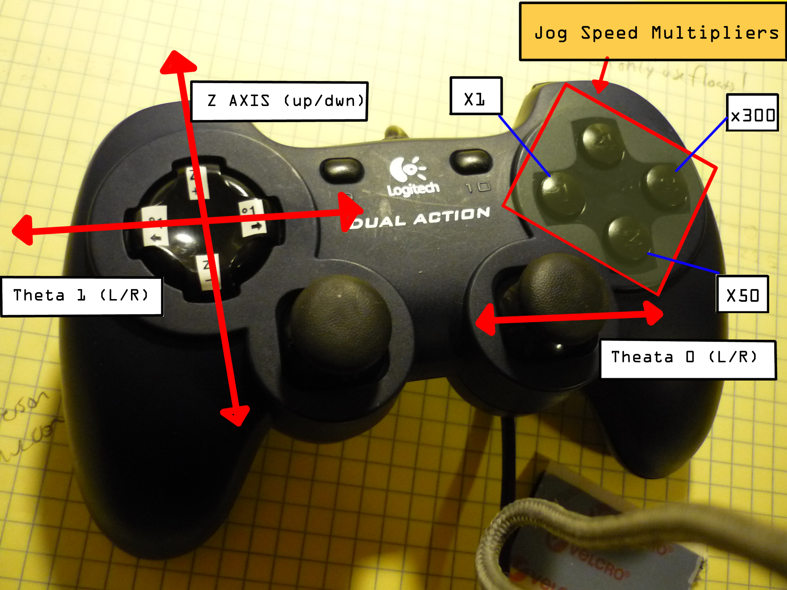
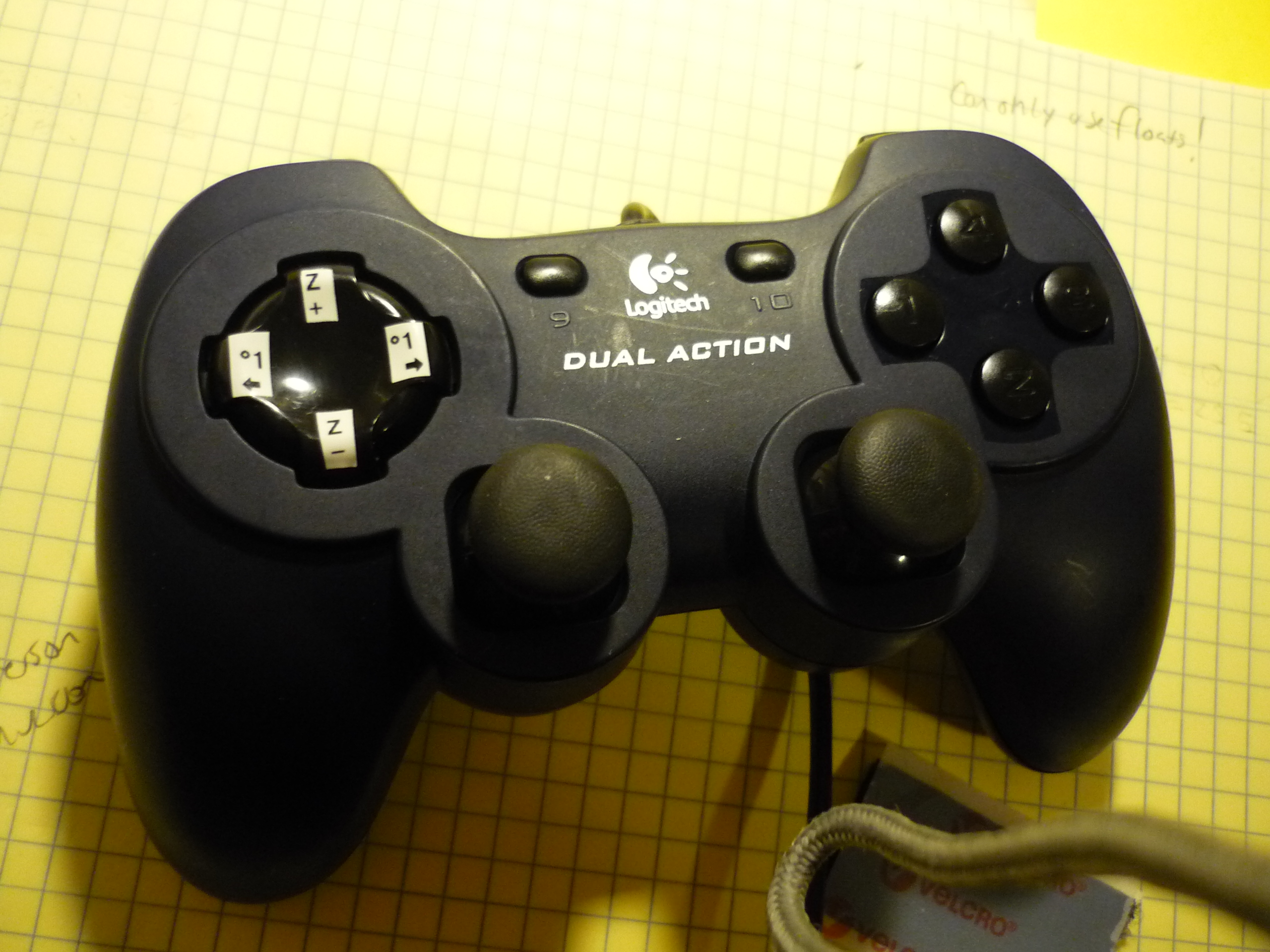
| Joystick
Interface To preform manual homing, or just putz around with a robot, i use a Logitec usb game controller. Its intuitive to use and more functional than virtual buttons. To add the game controller functionality, the following mods to my postgui file were made: 3 nets were made to vary speed (1-3). The speed was bounded by setp scale parameters setp
mux4.0.in1 50
In
this case, holding input 1 while preforming joystick motions scaled by
a factor of 50 steps/min (SLOW), whereas switching to holding input 3 scaled by a factor of 800
steps/min (FAST)setp mux4.0.in2 200 setp mux4.0.in3 800 |
|
| Mating
g-code from skeinforge into Linux CNC Skeinforge [Link] is an amazing tool for slicing a model, starting as an STL file, into a series of G-Code commands that reprap or even Linux CNC can make use of. There are some extra features that skeinforge puts into a g-code output file, to control extruders, fans, and heaters. These 'extra features' will throw errors in a plain-vanilla linux cnc setup. These are 'M-codes', listed on the rep-rap wiki [link]&[link]. Without 'm-files' present in the location speficied from the HAL file, linux cnc will throw an error. |
Examples: M101: Extruder on
(fwd)
M102: Extruder on (rev) <'oozebane' skeinforge, useful for preventing extruder oozing> M103: Extruder off M104: Extruder Set Temp M106: Turn on Fans M017: Turn off Fans |
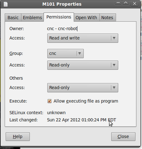
| Example 'M-code' file The following is a code-snippet from my initial M101 file. Its located in /home/<machine_name>/emc2/nc_files #!/bin/bash
All this m-file
does is call halcmd and set pin 09 of the parallel port to a logic '1'
output. # file to turn on parport pin 09 to on halcmd setp parport.0.pin-09-out 1 exit 0 Finally, a PSA: To
verify that an M-File is executable, graphically, simply right-click on
the file, goto 'permissions' and doublecheck that 'allow executing file
as program' is checked off. Verify for each M-File you make.
|
 |
| Axis
Feedback Display The Axis feedback display (while limited at the time of release of this project), displays each axis's position in a dial format. This file is stored as scara.xml in the config directory. An example of each axis feedback is shown (right). The rediculously oversized ms-paint arrows are not included. |
 |
| Doublechecking the Thermals: Extruder Celsius Calibration | Images |
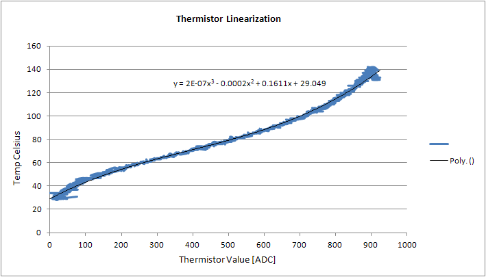
| How
linear is that thermistor? I started off with the makerbot MK5 print head, and with a few modifications (removing the plastic mounting base). The print head came with a thermistor for monitoring the print head temperature. I had allready tied together a microchip MCP9700 [Datasheet] super linear thermal measurement IC with analog out, so i perched the two closeby, and DAQ'd the actual temperature vs the voltage response of the thermistor. From this plot, i excel'd a 4th order equation to convert the thermistor's non-ideal resistance / degree F into a linear plot. The thermistor's resistance vs temperature eq: y = 2E-07x3 - 0.0002x2 + 0.1611x + 29.049
|
 |
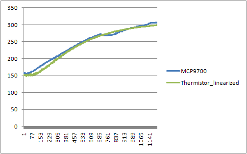
| After
Linearizing The Thermistor: The following plot displays the resultant linearized thermistor output [From 150 F to 300F]. The microcontroller converts the analog 10 bit ADC, averages, and applys the difference of the two transforms above to plot actual temperature. They follow quite a bit better, and the differences in temperature can be attributed to a combination of the two sensors not being right next to each other. |
 |
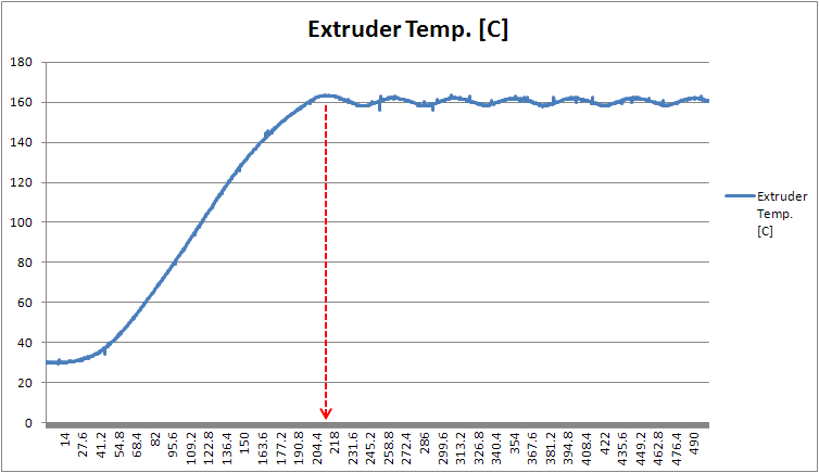
| Extruder Warm up: A completley linear power vs temperature plot would result in exceedingly long extruder warm-up times, so i broke up the warm-up into a 2 part operation: 1: Constant Power
heat up of extruder to 10 degrees C below the extruder temperature
setpoint
2:
proportional power backoff up to setpoint
The
advantage to this is extremely short warm-up times, due to
bulk
heating, and very limited overshoot for the temperature at the desired
setpoint. The actual overshoot derives mostly from the fact that this
is a non-feed forward reactionary control. As there's a large thermal
time constant for the extrusion head, input energy (heat) takes time to
propogate through, this can be corrected for by factoring in the
thermal mass of the extrusion head and a first order estimation of
convection losses. |
 |
| DC Extruder Control | ||
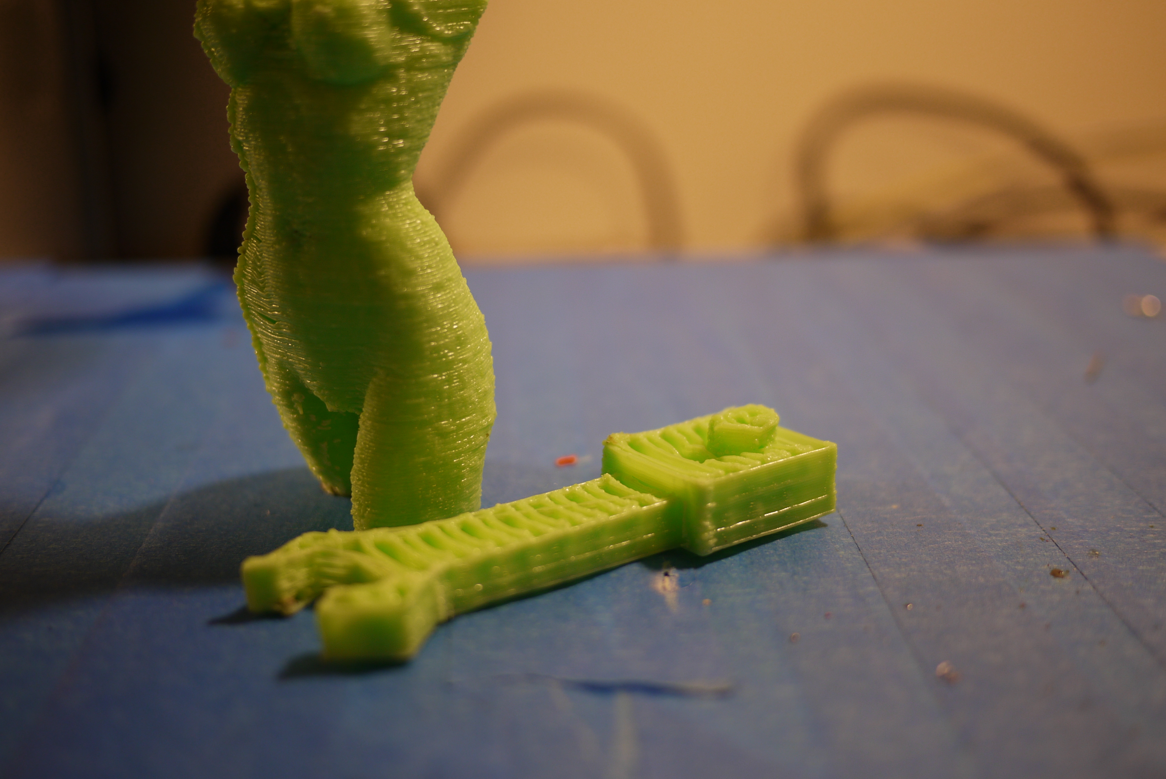
| Initially, for the extruder
controller, a simple 'if extruder step = 1' extrude,
otherwise, stop extruding. This does have some detrements,
namely the 'dc-servo drool' issue. As shown on the pictures (right)
between the central point and the outer parts, a whisker of ABS
branches across. To mitigate this, and a pile of 'whiskers' i used the H-Bridge i developed earlier to quickly reverse the motor output for 100ms when the 'STEP' line changed state. Reversing the ABS feed temporairally greatly reduces the pressure in the extrusion head and stops the excess extrusion quickly, mitigating this issue. Later on i found that 'oozebane' in skeinforge has a specific M-Code for preforming this task, and i was able to call this out in software (model) versus on the embedded micro, controlling the extruder |
 |
 |
| Skeinforge:
Splicing a 3d model into a pile of G-Code traces
|
||
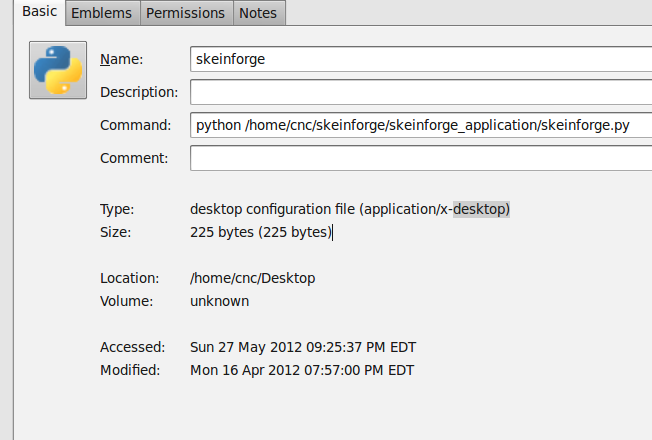
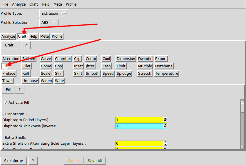
| Skeinforge
is an awesome splicer that grabs an existing 3d model, in STL format,
and will slice it into a gcode path file, based upon input from the
user. There are a daunting number of variables to tweak in the slicing of the 3d model. The wiki [link] and makerbot config [link] were helpful in providing overviews and notes. I started by grabbing a recent build of skeinforge [link] unzipping the folder and in my case, storing it in /cnc/skeinforge. Its important to note, that for 'skeinforge.py' I selected 'allow executing file as program' from the file permissions tab. I created a desktop shortcut, with the path shown (left) |
 |
 |
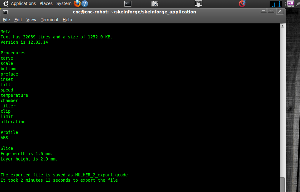
| Running Skeinforge After tweaking the settings listed in skeinforge, save and close the script. Using skeinforge to a STL model to Gcode is as simple as opening up a terminal,cd sk cd'ing to the directory its installed and running 'python skeinforge.py FILENAME.stl' where filename is the STL 3d model. In this case i had the STL model in the same directory as the skeinforge python script. Skeinforge will create a FILENAME.gcode as an output file in the same directory as the initial file. |
 |
 |
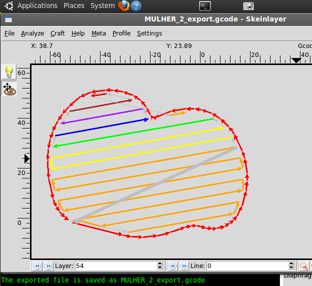
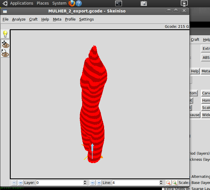
| Analyzing the Path Files Skeinlayer (selectable in the 'analyze' tab) previews the paths generated in gcode. An animated version of the print is available by clicking through the layer tabs on the bottom left corner. The change in color denotes a seperate path. Skeinso is a 3d viewer of the paths in gcode, which is useful for verifying how the path file looks, was the infill applied, and if the layering characteristics were good for the specific model |
 |
 |
| Game Controller Robot Control & Configuration | ||
| As a jog interface, a Logitec
'Dual action' USB game controller was used. Prior to using this, i used
some virtual buttons on the emc2 interface, and clicked/held the mouse.
This was far more intuitive to use and moving 3 axes around became
trivial. The button mapping is shown (left) Sample code is available above to detail how to integrate the device. It mounts in /dev/input, in this case as input0. I based this integration from some work listed here [Link] |
 |
 |
| Documentation
/ Timelapse Camera |
||
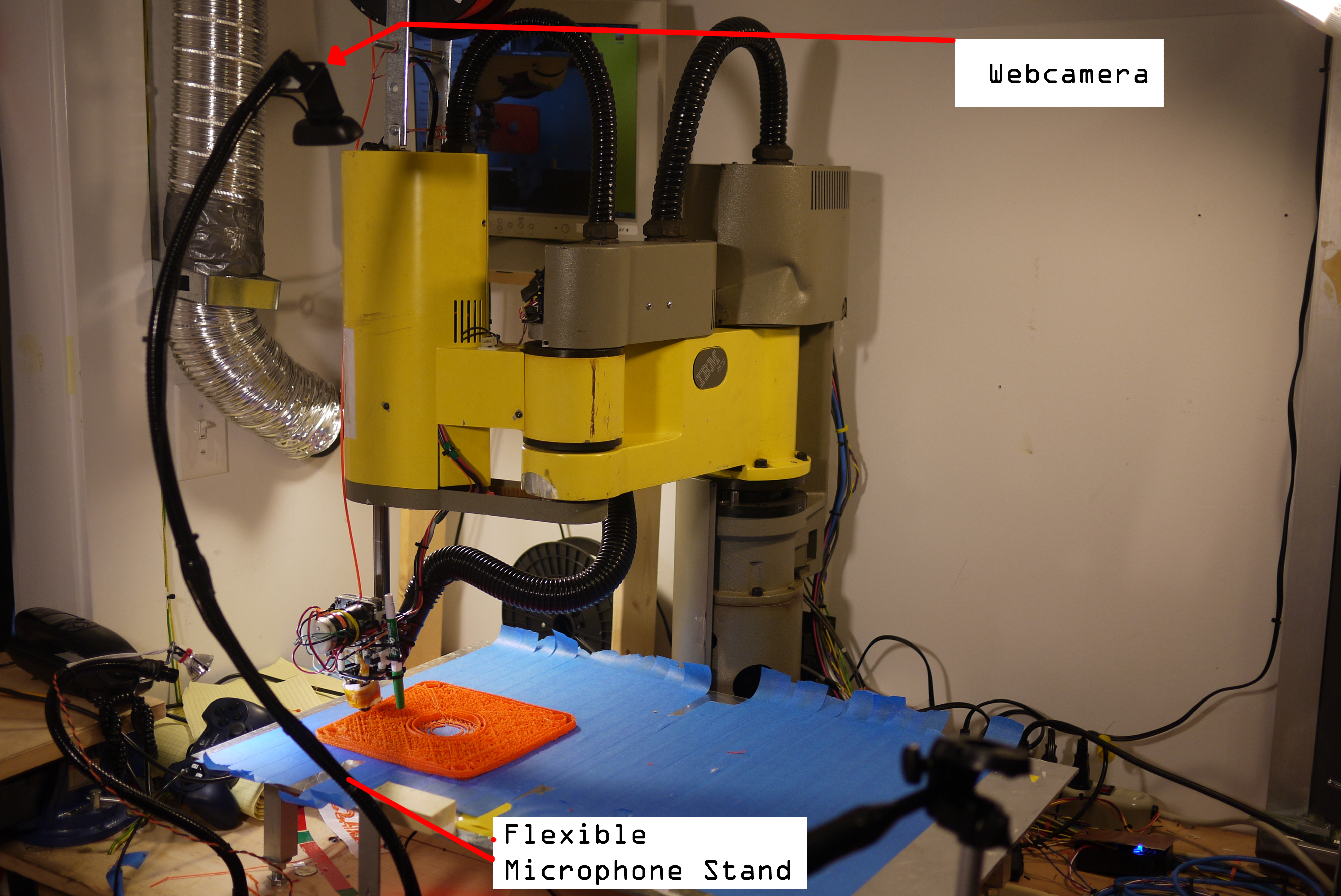
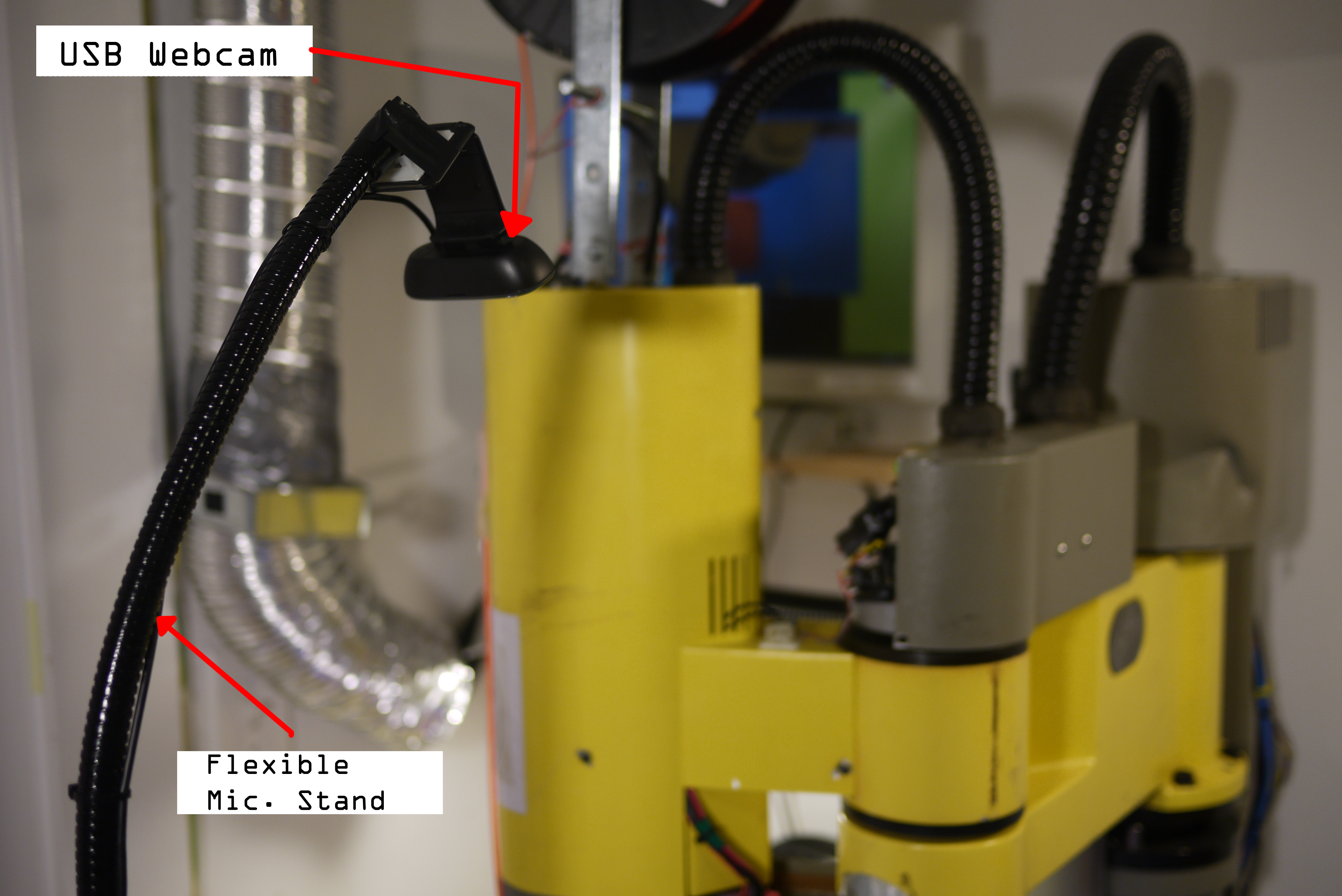
| I
wanted to document some of the longer 3d prints (2 hours +)
however, i lacked a camera that could record / had battery to
run
for hours. I snagged a used logitec webcam [link] and some microphone
stand [link] and 6' of USB extension
cabling to create a movable,
positionalble timelapse camera mount. As the webcamera's mass is less
than 100 grams, the flexible microphone stand can hold it in a fixed
position without noticable droop. The microphone-stand assembly is
bolted to the work surface. The only cavieat so far has been vibrations coupling from the robot to the flexible camera stand, resulting in a bit of wobble. It may be a better move to bolt the flexible webcam stand to a surface not tightly coupled to the vibration source. |
 |
 |
| Timelapse Script For the longer time-lapses where only 1-2 fps was needed, i created a python script. This was useful as it was far less resource intesnive, in comparison with running guvcview which, can cause a lot of system latency. The only dependency is uvccapture, which is installable by a simple 'sudo apt-get uvccapture'. This script takes a high-resolution image 2x / second and puts it in a folder labeled 'image_folder' in the same directory as the script. Each image has the system time as its filename. After complete, a ffmpeg script generates a giant AVI from the raw images. There are a number of other ways to accomplish timelapse ->pile of images -> avi documented on the net. |
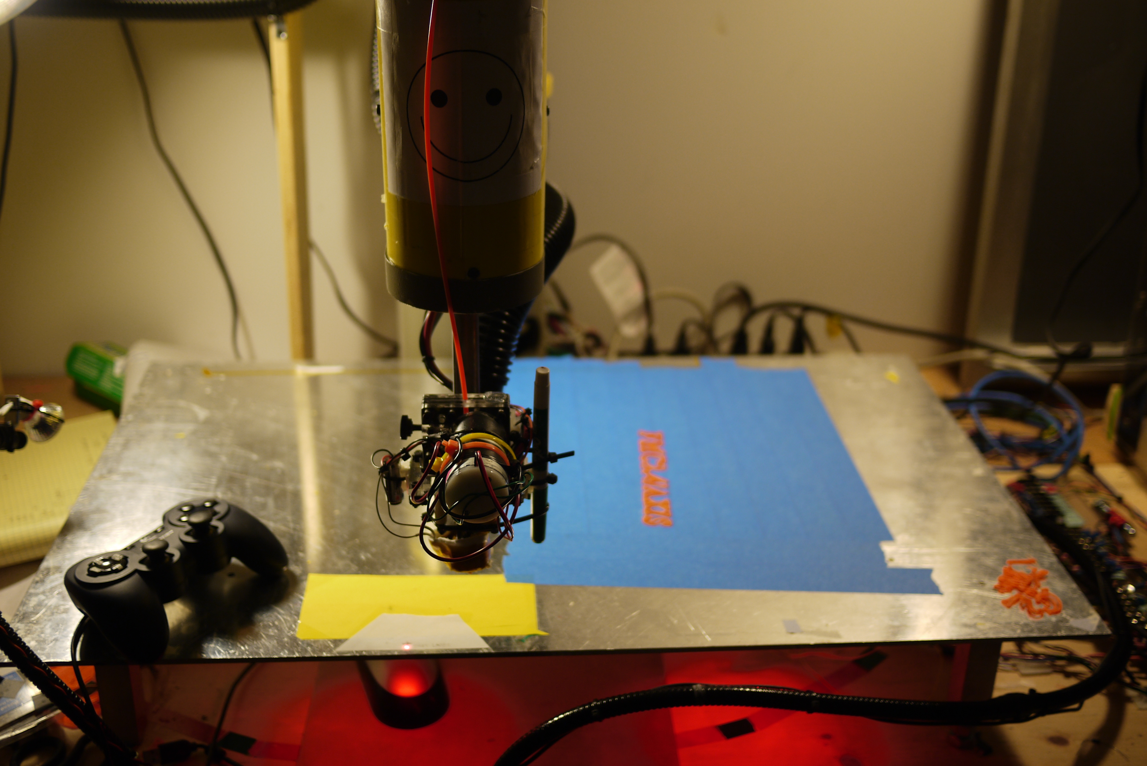
| Printer
Outputs |
||
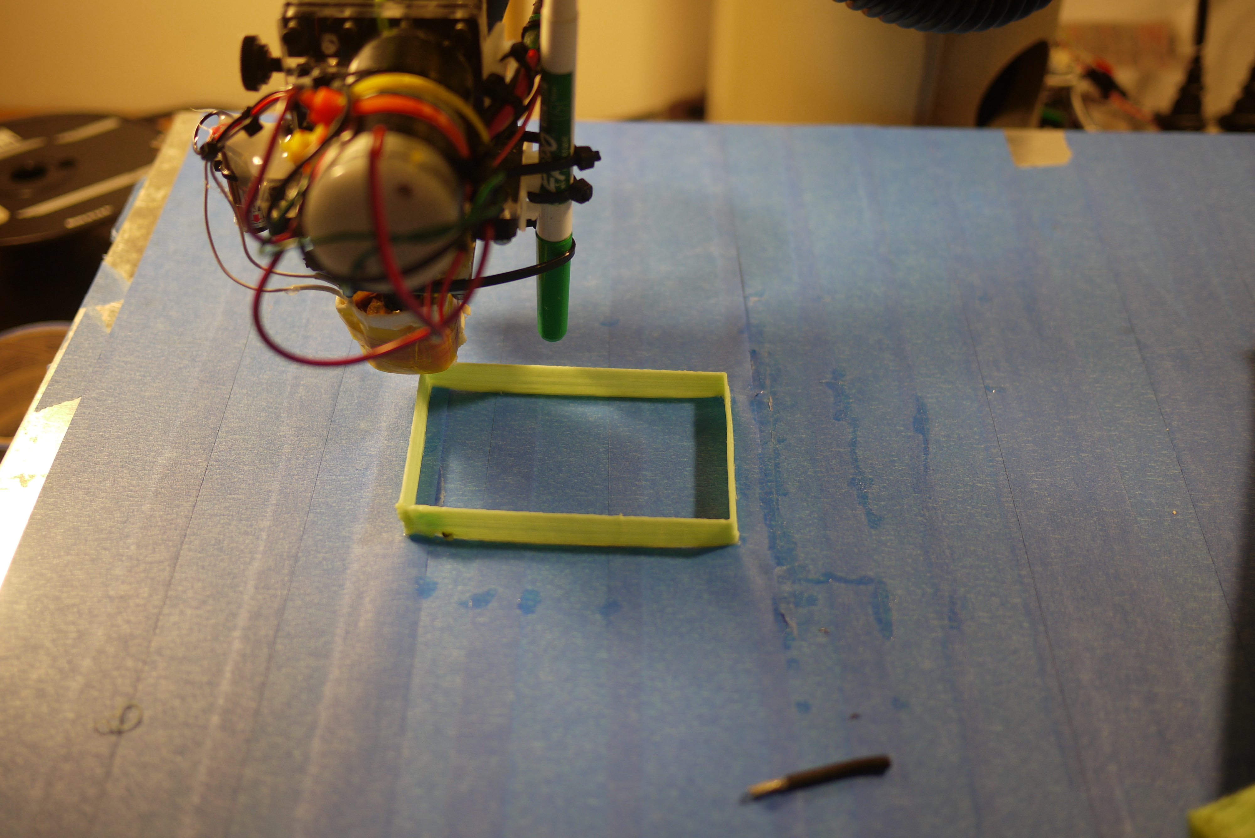
| Blue Painters Tape is amazing I tried a number of work surfaces for printing ABS onto, ranging from saran-wrap all the way to waxy parchment paper [shown left]. Printing directly to the aluminum build table, even when heated, proved too dificult. Saran-wrap warped, wax paper was too compliant and the abs would easily dis-engage from the surface. Plain construction paper worked well, but was very difficult to remov e from the final print. As a result i 'painted' the projected build area in strips of tape, which was easy to remove from the work table, and wasy to peel away from the ABS printed part. |
 |
 |
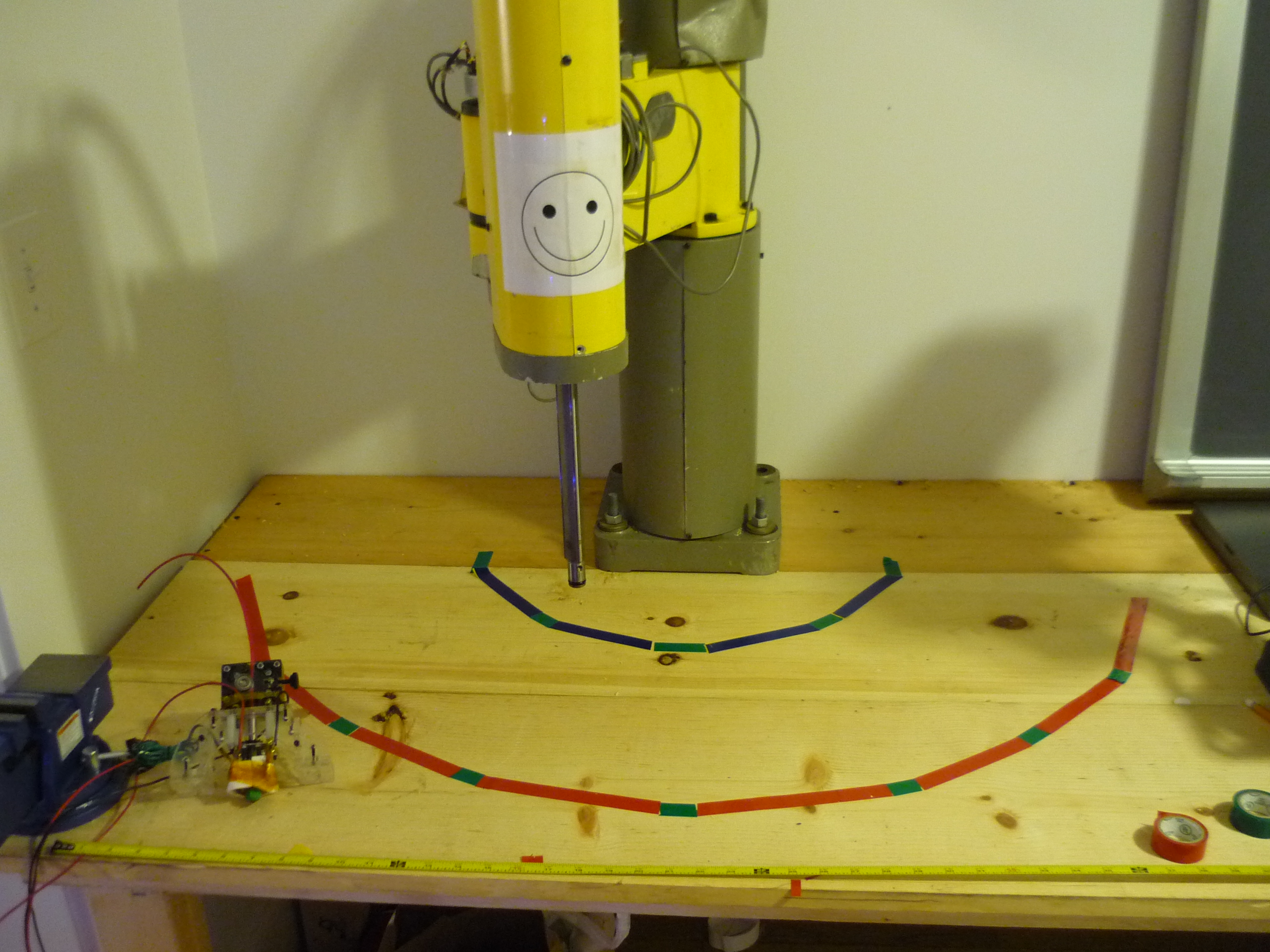
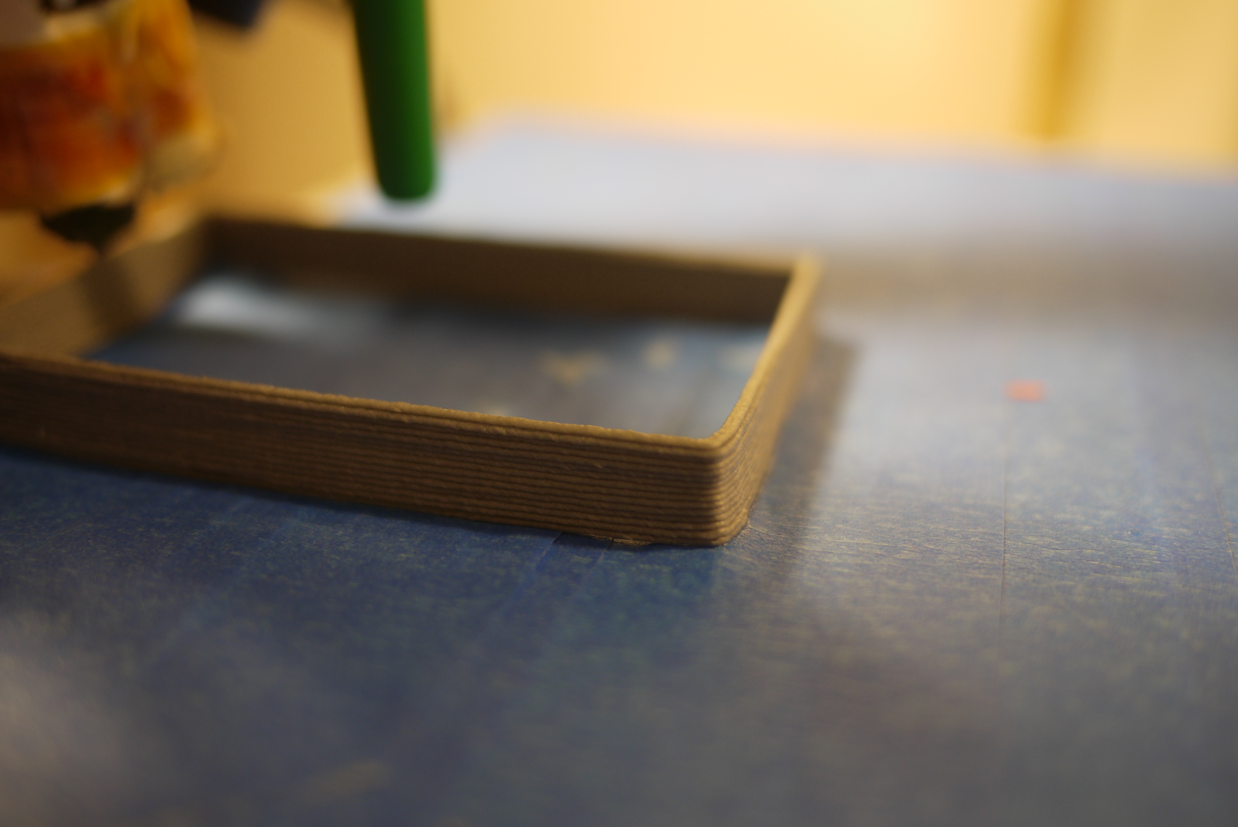
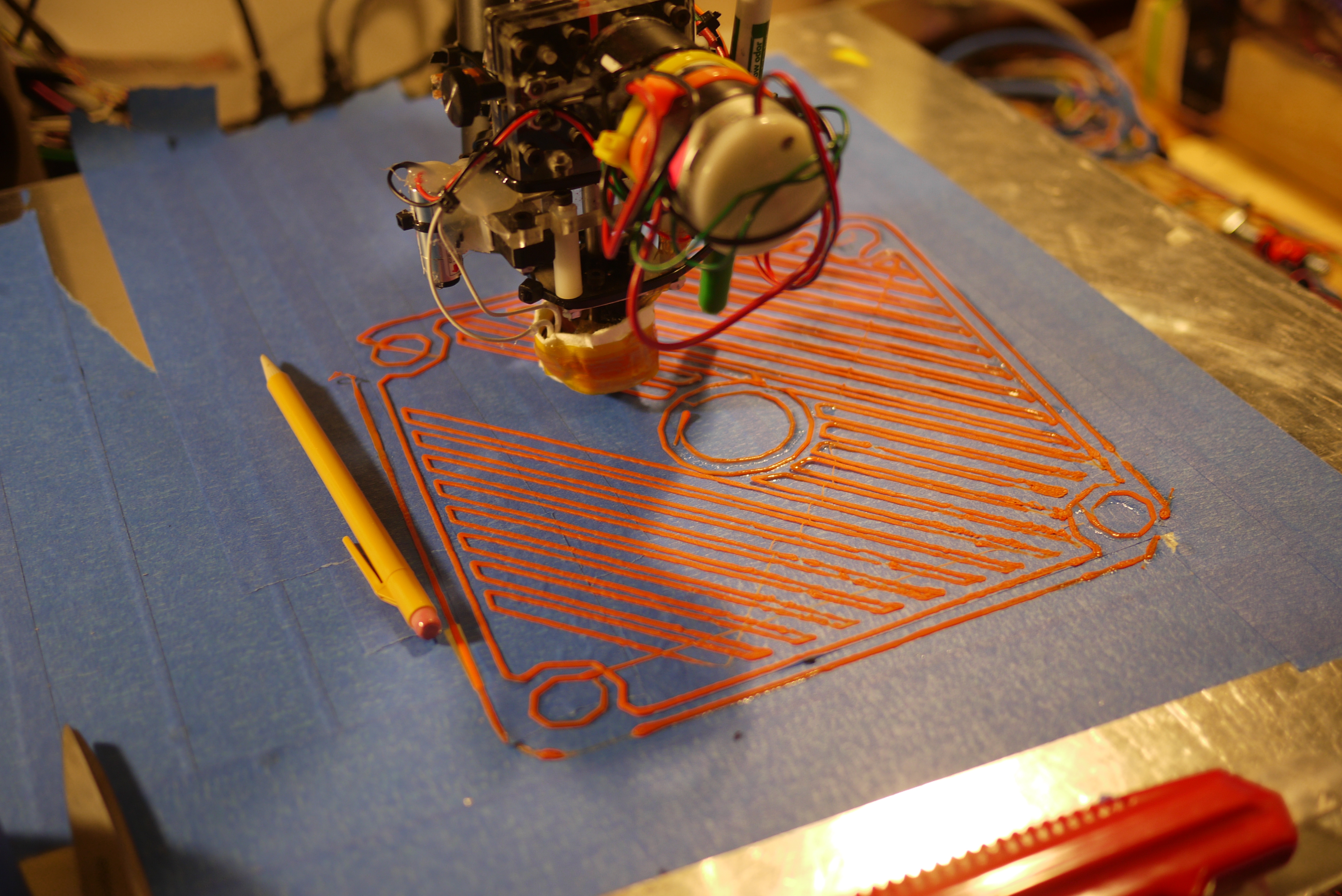
| Corners
and Lines After the first test prints were complete, I spent some cycles doing PID controller (theta 0) tuning. I was able to null out most of the over shoot to allow for strait lines and relativley crisp corners. Previously, oscilations were visible in the print. They were semi-periodic, i was able to caliper the distance between the peaks out, determine the difference, and tweak the error band used to tighten up the control loop. Initially i ran into some issues with corners warping up over time, but that was mitigated by turning the heated build platform up to 90C, which ended up pulling close to 300W alone. |
 |
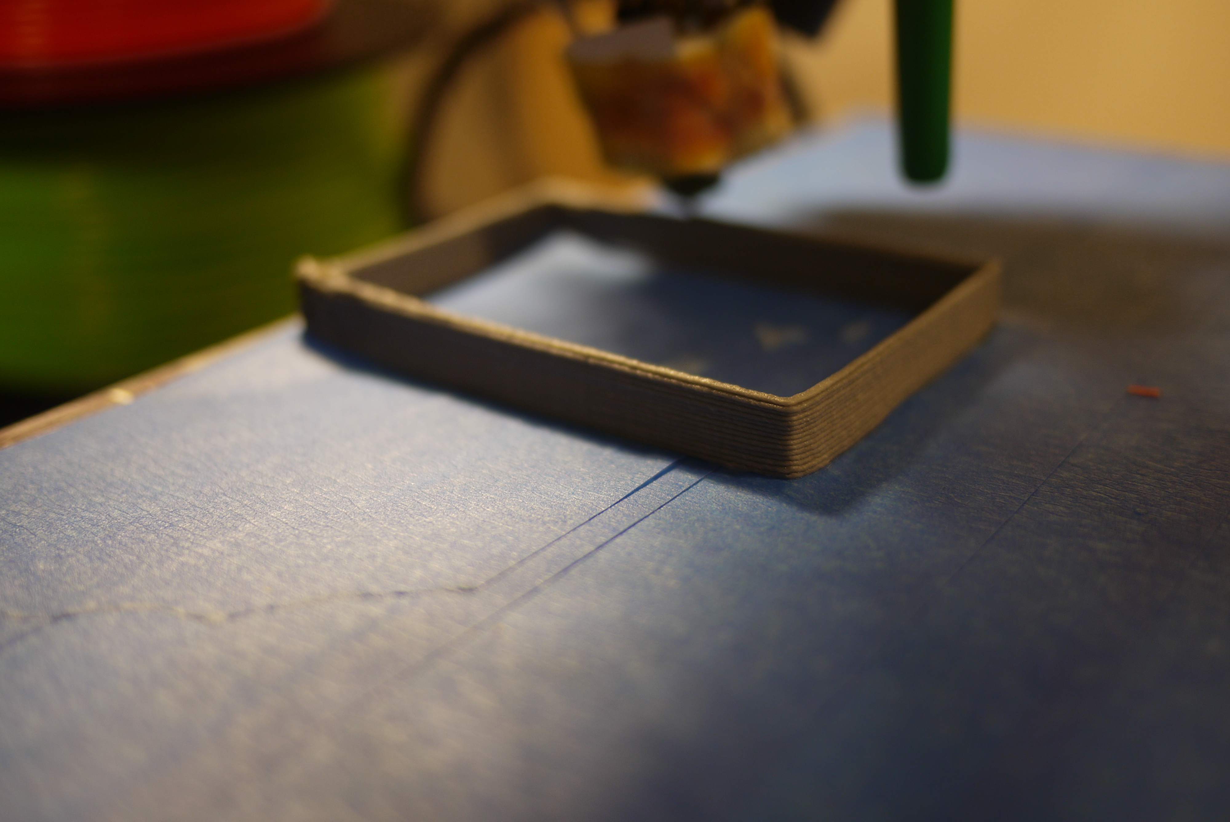 |
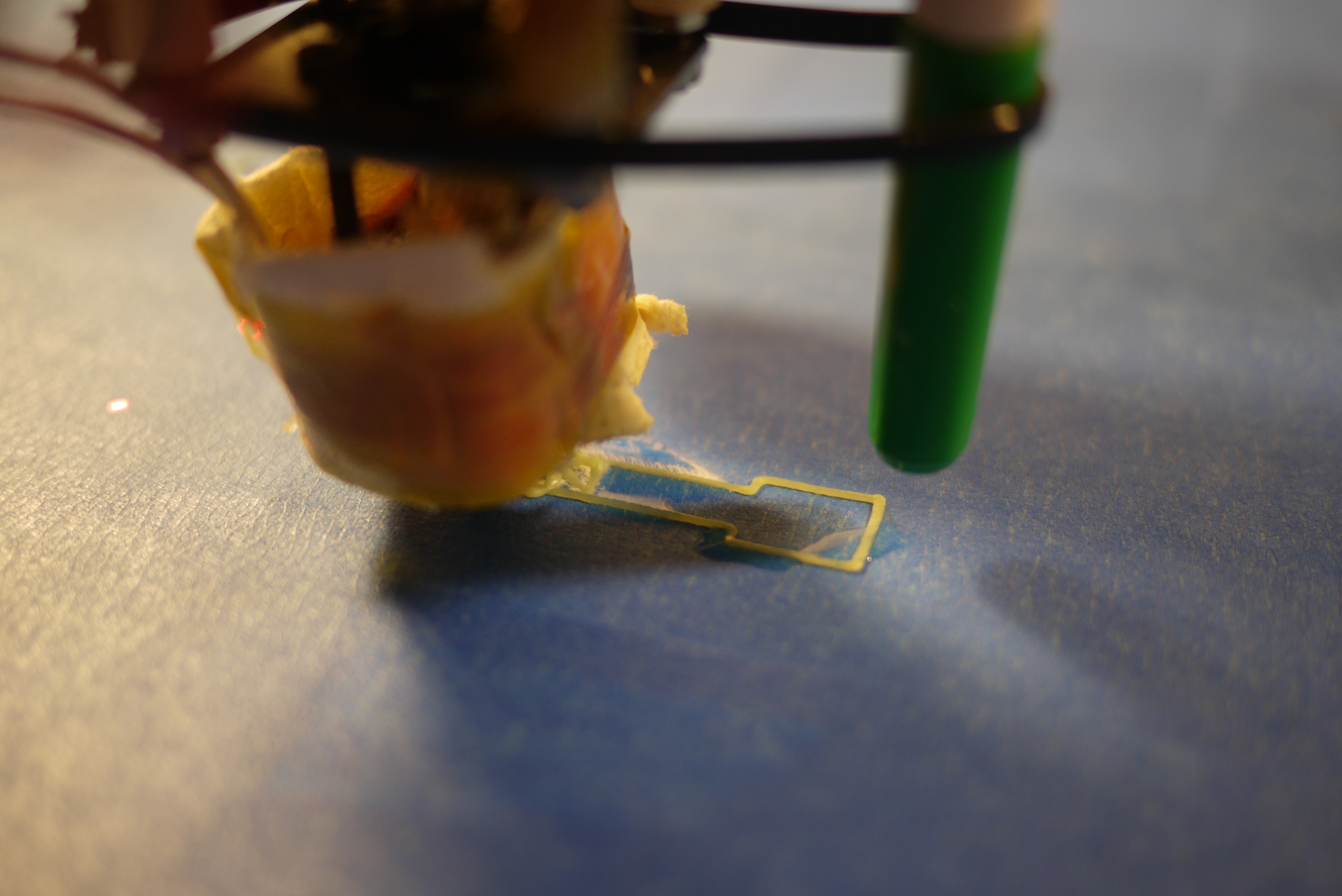
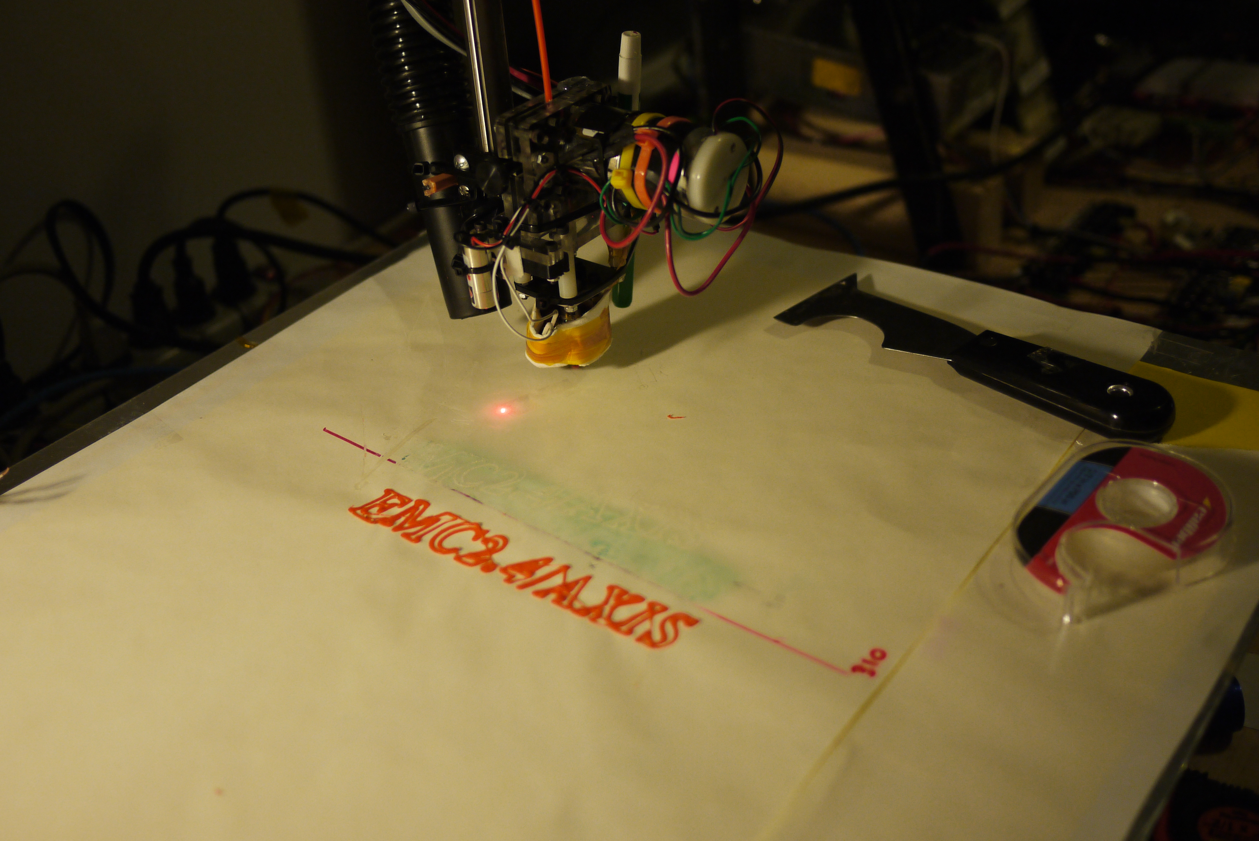
| The
start of the first
attempt at a larger format print. Note that some of the corners are
CA'd (superglued) down to halt the warping of corners. A standard
twist-style mechanical pencil is sitting on the left hand side of the
print. This print only occupies 1/3 of the build space. There were some
issues on the print table's height tolerance,
and as a result some areas were a bit less defined than others.
Initially i hadnt noticed this, as the smaller prints occupy a fraction
of the space. One of the main learning points for these larger
prints is compounding
errors. For the smaller prints, a missed encoder interrupt
once every 100,000 encoder feedback loops wasnt horrible, but, as the
print scaled up, the became more visible. |
 |
 |
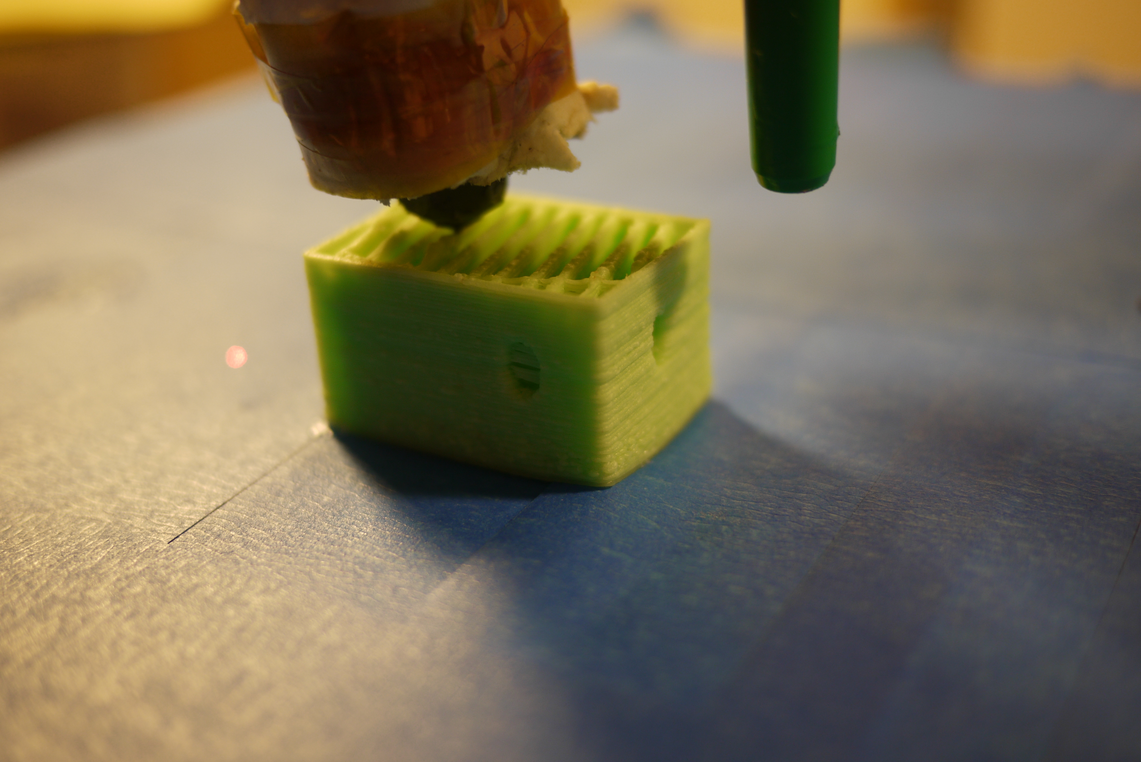
| Speed Settings This is the first successsful no-lateral-shift print, using green ABS 3mm filament. This is the body and arm for a small robot [link] |
 |
|
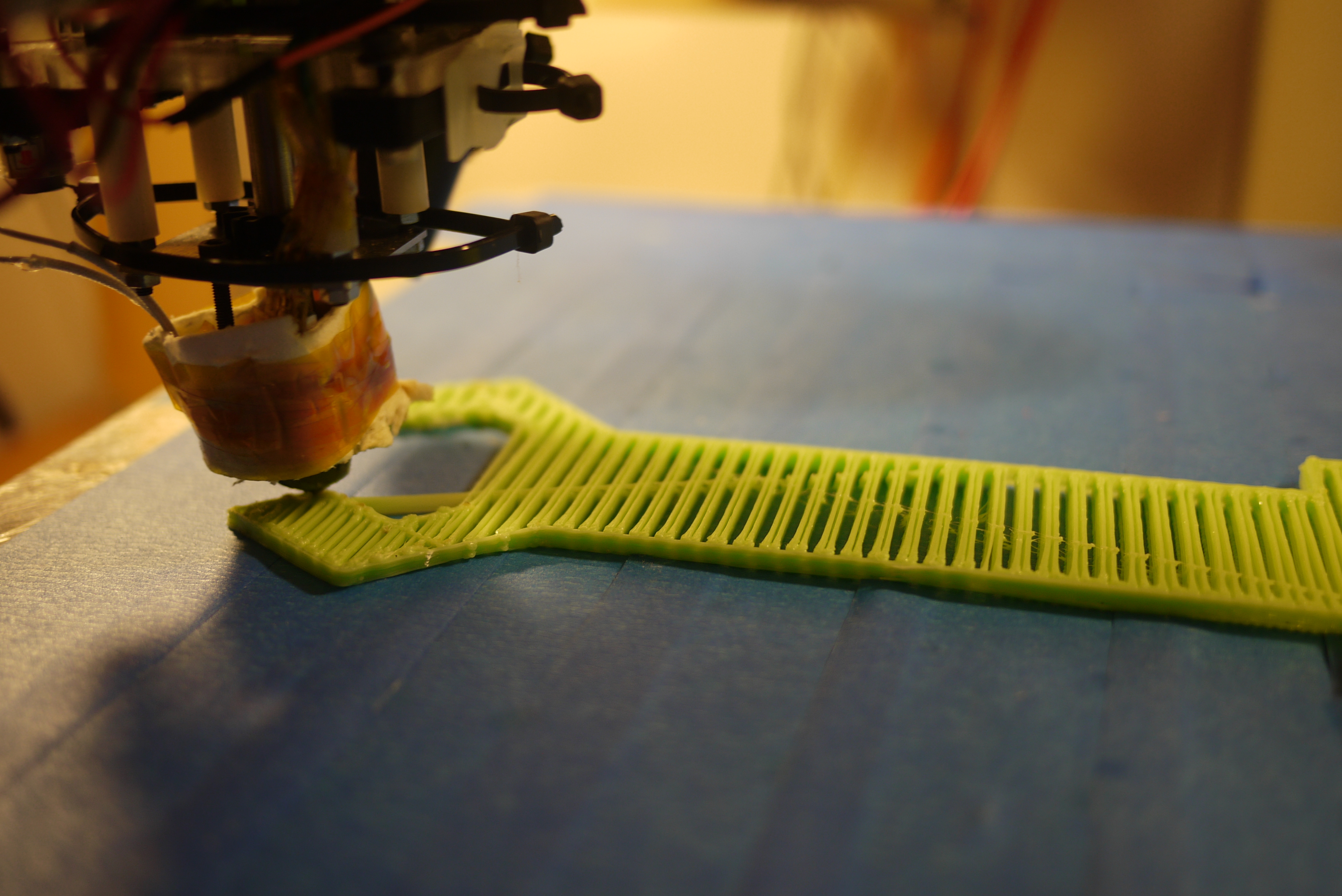
| Move
the head faster, pack layers tighter, run everything hotter In efforts to increase the resolution of the print and get rid of some blotchy artifacts that occur at low speed, higher extrusion rates, I ran the heated build platform hotter, spent time optimizing the control loops to allow for faster acceleration on all axes, and the quality significantly improved. Printing faster at lower extrusion rates required changing the height-per-layer, however, the layers ended up crisper and the prints seemed more stable & repeatable. Still havent figured out why skeinforge is sticking with 'line' infills, when i ask for hexagonal... |
 |
 |
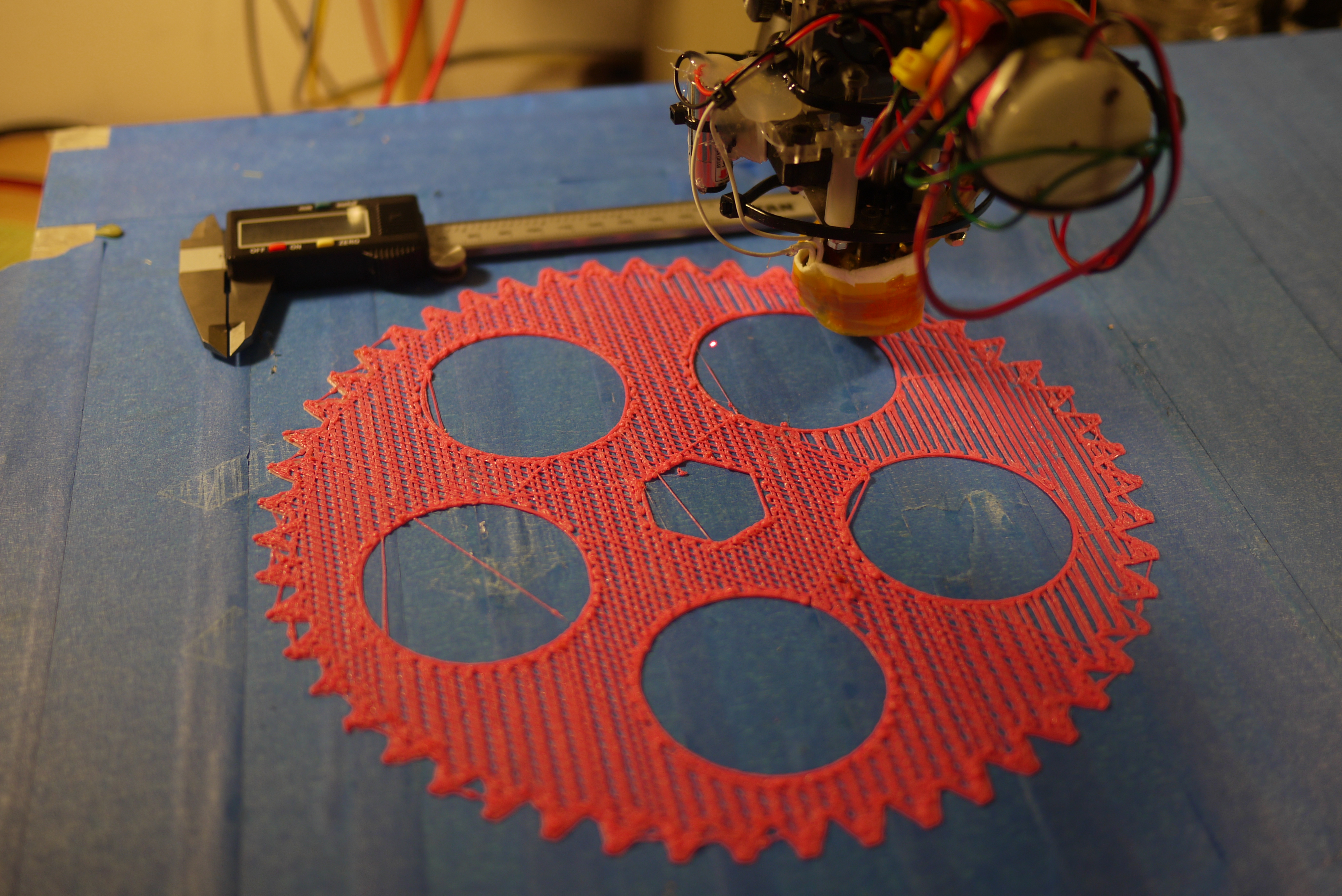
| Increasing
the size With the newer heater upgrades and push for a faster print speed (2400mm/min), printing large tighter meshed objects became easier, this print is roughly 9.2 inches in diameter, 2/3rds of the max print size for this shape. |
 |
 |
| Downloads |
Release 1: 6/02/2012 |
Release 2: 7/02/2012 |
| Full EMC2 Configuration files and directory structure in .rar | [Configuration directory, Zipped] |
|
| Extruder Bidirectional Drive
Firmware |
[Compiled, Mega168] [Source] |
|
| Theta 0 Encoder PID Drive Firmware | [Compiled, Mega48] [Source] | |
| Fan + heated platform Drive Firmware | [Compiled, Mega48] [Source] |
| Updates |
| [6/6/2012]
MORE HEATED BUILD PLATFORM NONSENSE A colleague showed off the latest from makerbot and I found the heated build platform temperatures were actually significantly higher than the 65C i had been running my build platform at. Previously i had been using ~60-65C, which was the max output. I added 2 extra heated pads (from marathon) and 2x200w 24v power supplies (awesomely donated from a colleague) to allow testing up to higher temperatures. The higher temperatures allow for printing without tremendous amounts of warping. Previously, i used superglue to tie down the corners of the print to the blue painters tape (shown, far right). While this worked short term, larger prints had enough thermal stress to pull up the blue painters tape and continue to warp. |
 |
 |
(There's
other photos in the photo gallery)
Concluding
Remarks:For this project, I ended up going through an inordinate amount of blue-tape, I probably could have saved a few dollars by purchasing 4-pack rolls of tape. I need to move to a faster code implementation / faster clock rate on the theta0V2 boards to allow for faster build/print times. Currently the DC-Servo motor controller is the limiting factor for speed. Further development could increase this speed by at least 4 fold. As a general note, i'm currently running way lower resolution than a commercialy available printers, namely due to the infant-esque stage that the printer is in, the skeinforge/gcode splicer parameters are still being tweaked, along with the scaling factors of the motor drives. The actual drive hardware may change to incorporate a micro with a faster maximum clock, to increase the maximum speed of the theta 0 axis. Also thanks to David B. for the pointers on his scara setup. Hopefully the documentation presented above will be of use for future EMC2 projects focused on 3D printing.
Finally, if the makerbot folks want to donate a fancy MK7 print head, i'd gladly adopt it into the land of ubuntu cnc and document my findings without any questions.
References:
Thanks to [laserdude] for the PHYSCIAL COPY of the ancient SCARA manuals. They are a thing of beauty. [Note: large scanned pdf files]
I scanned almost all of them and uploaded copies of the manual here: (i looked thoroughly and they are out of copyright/have not had their copyright renewed)
| From the sponsors: |
If you have questions or comments, ask below or send over an email.
| Comments: |
|
HTML Comment Box
is loading comments...
|
(be
careful, im not responsible for your blown parallel port,
malfunctioning 3dprinted iron-man suit or vastly increased electric
bill)
Dane.Kouttron
Rensselaer Polytechnic Institute
Electrical & Electrical Power
631.978.1650
