Dane.Kouttron
[9.07.16] ULTRA OUTBOARD and STOLEN SCIENCE [48KW of ELECTRONS]
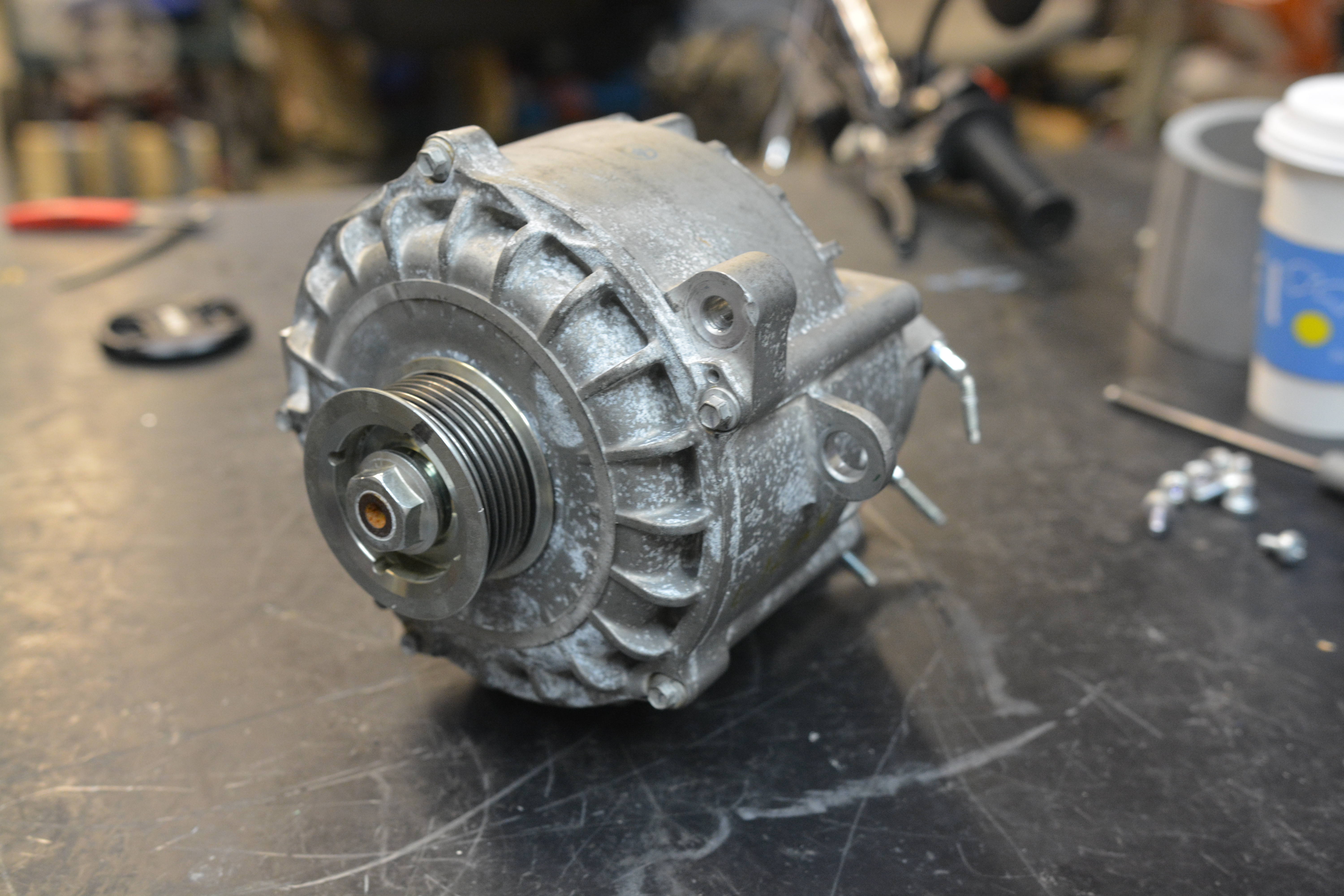
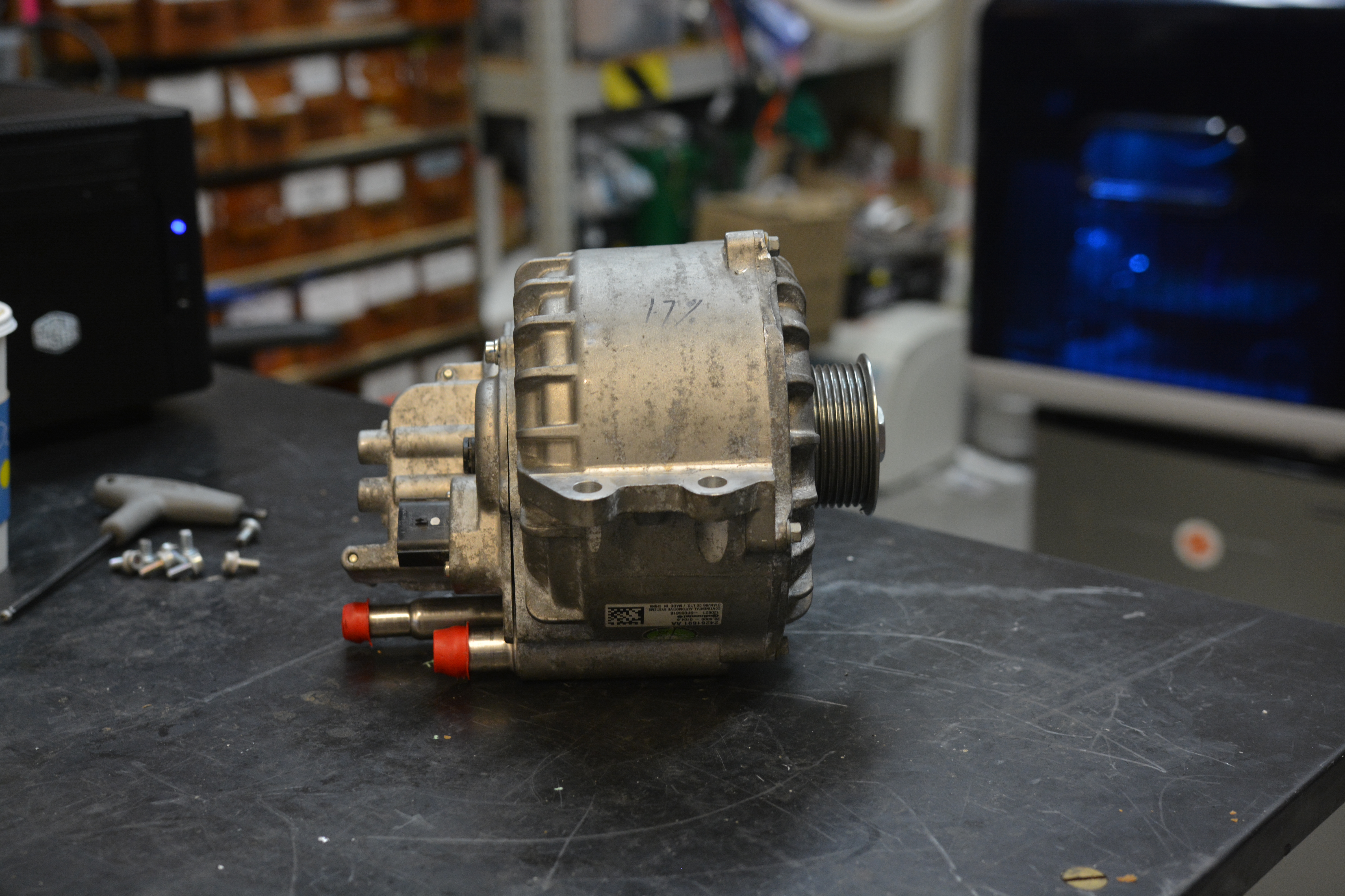
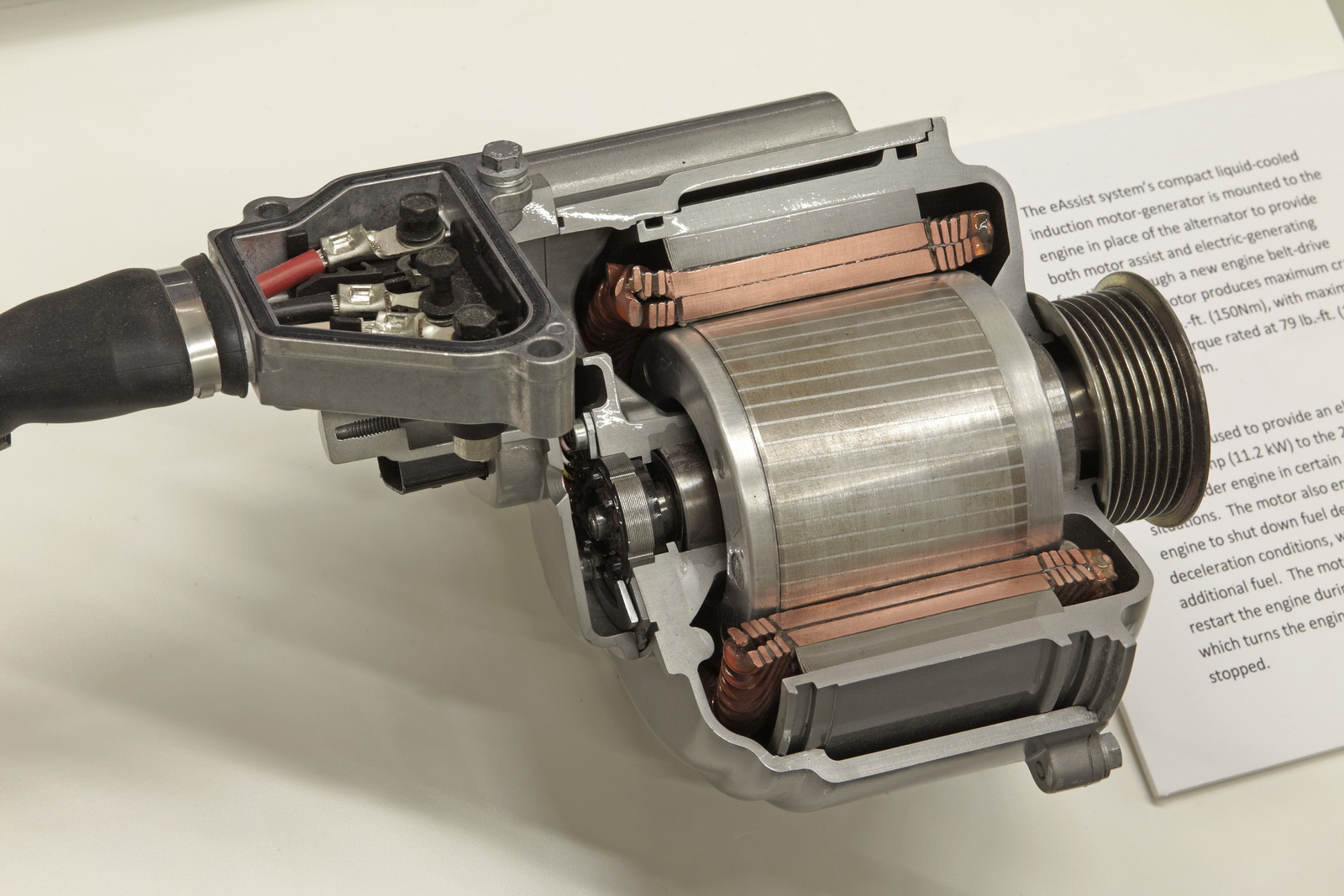
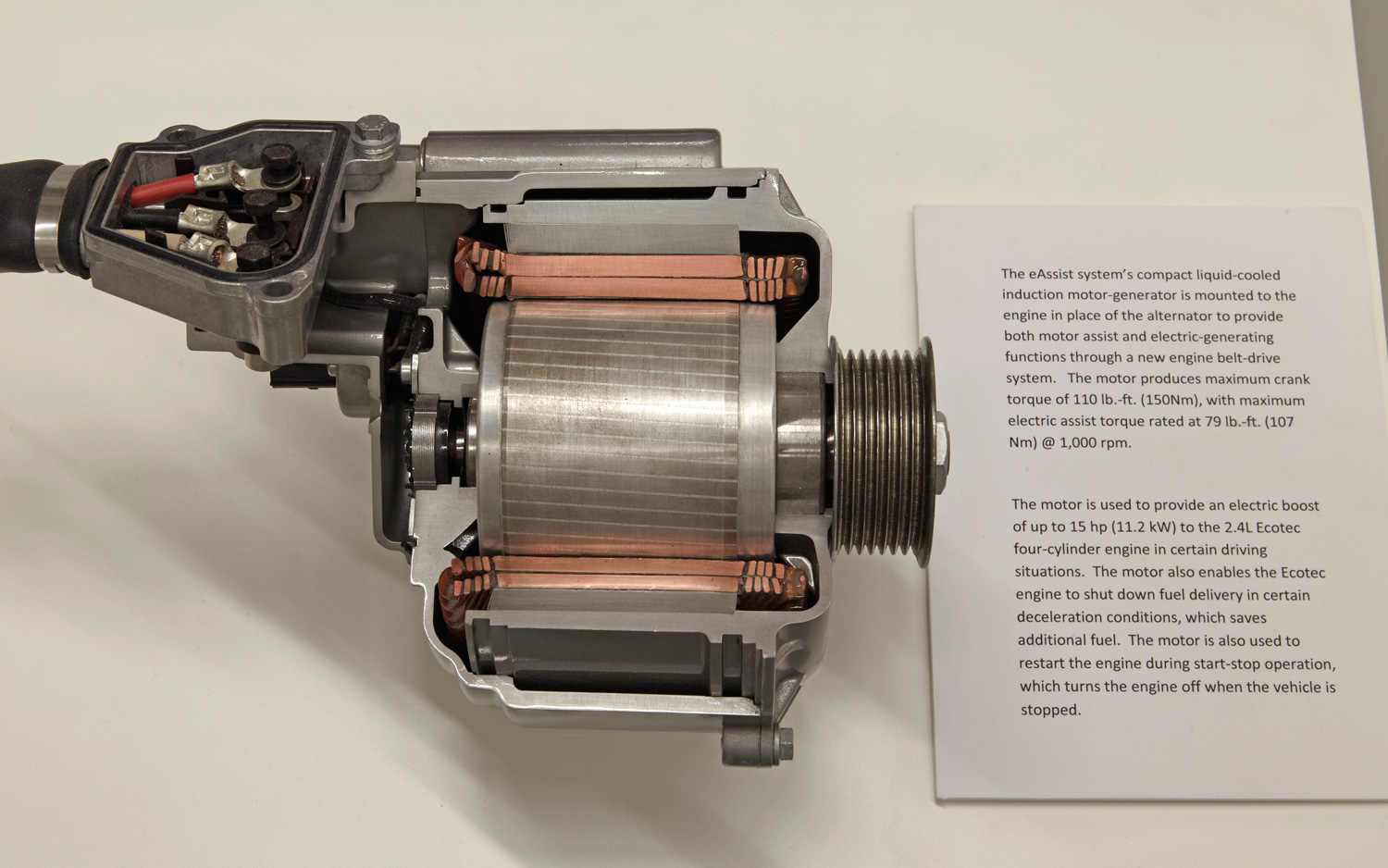
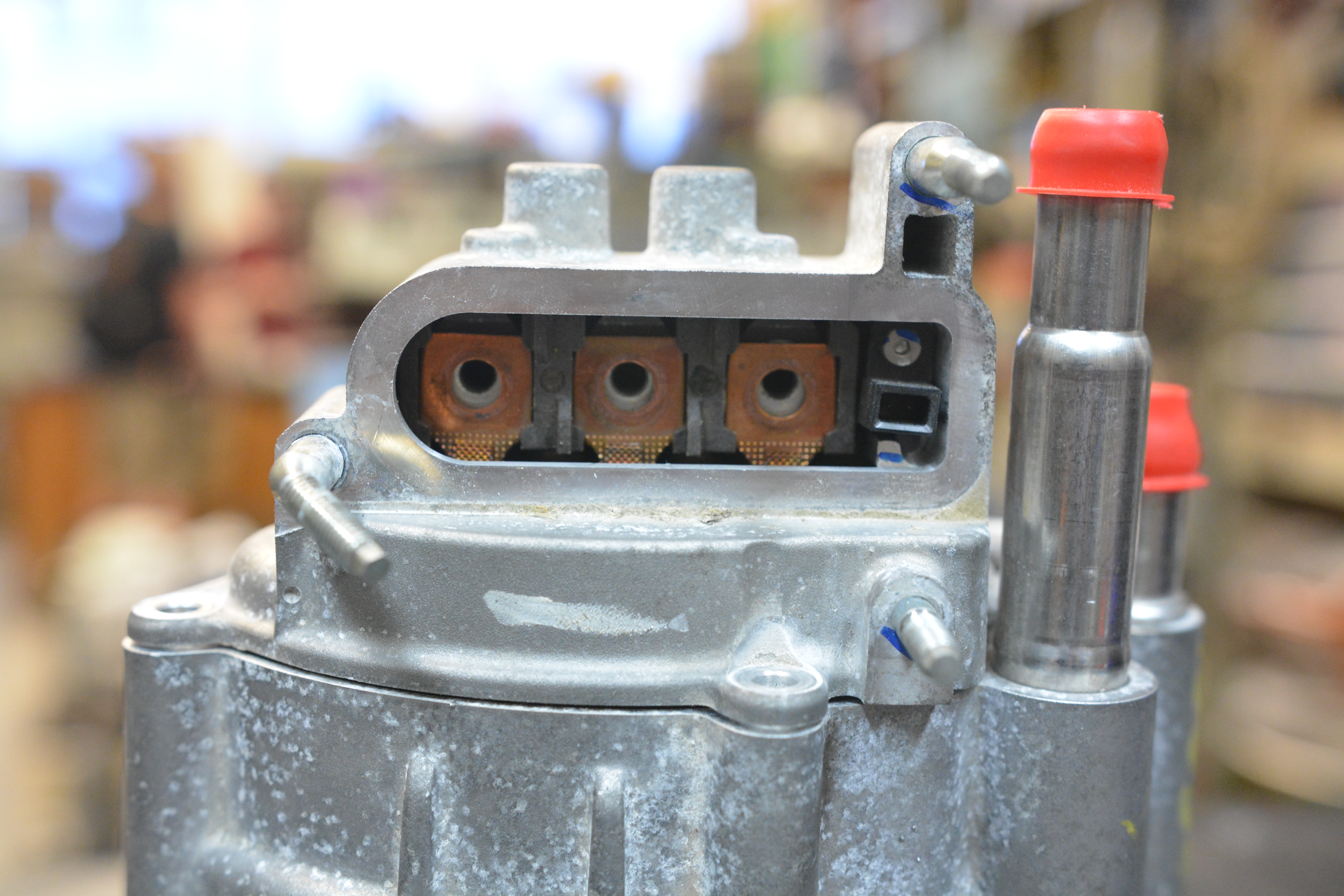
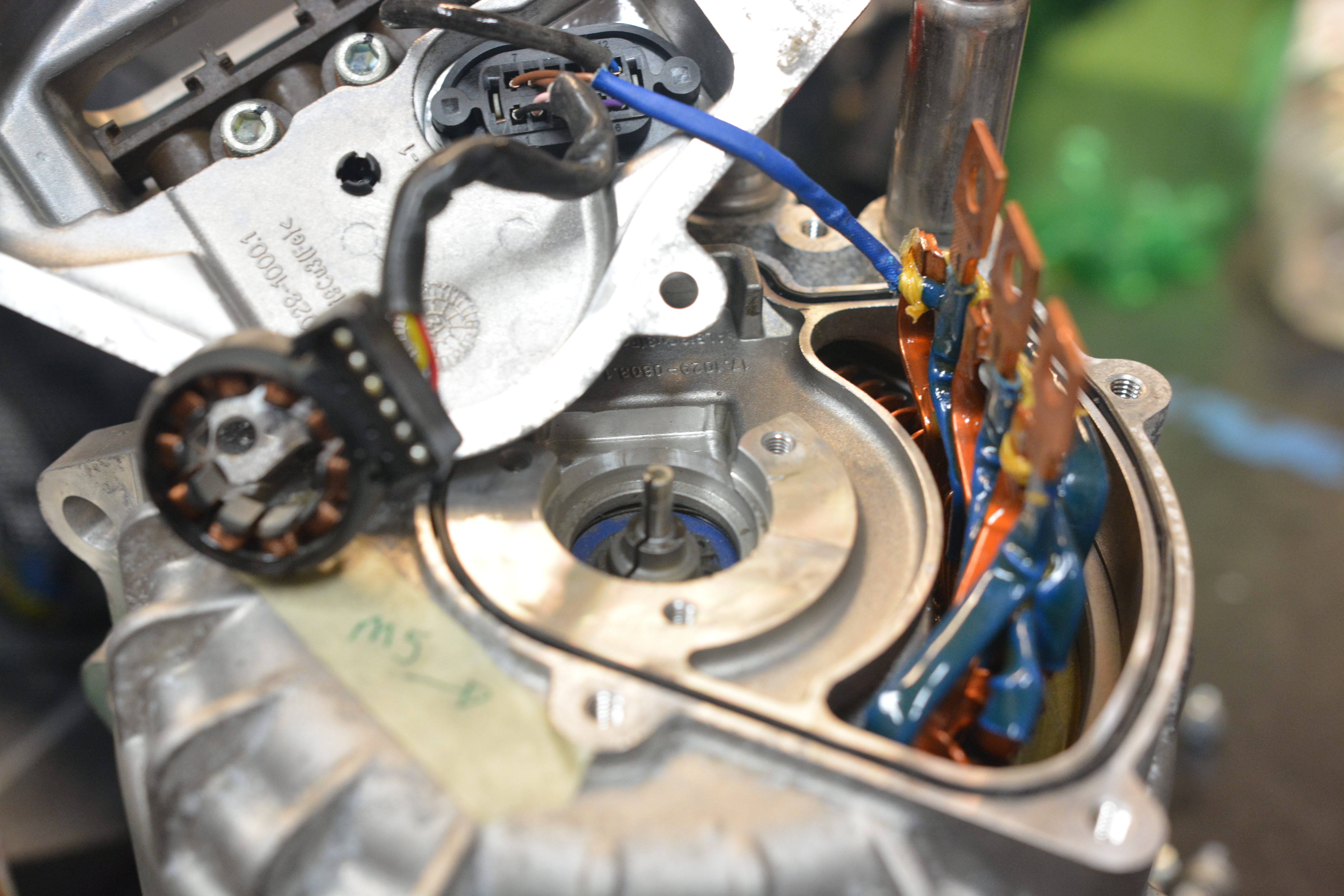
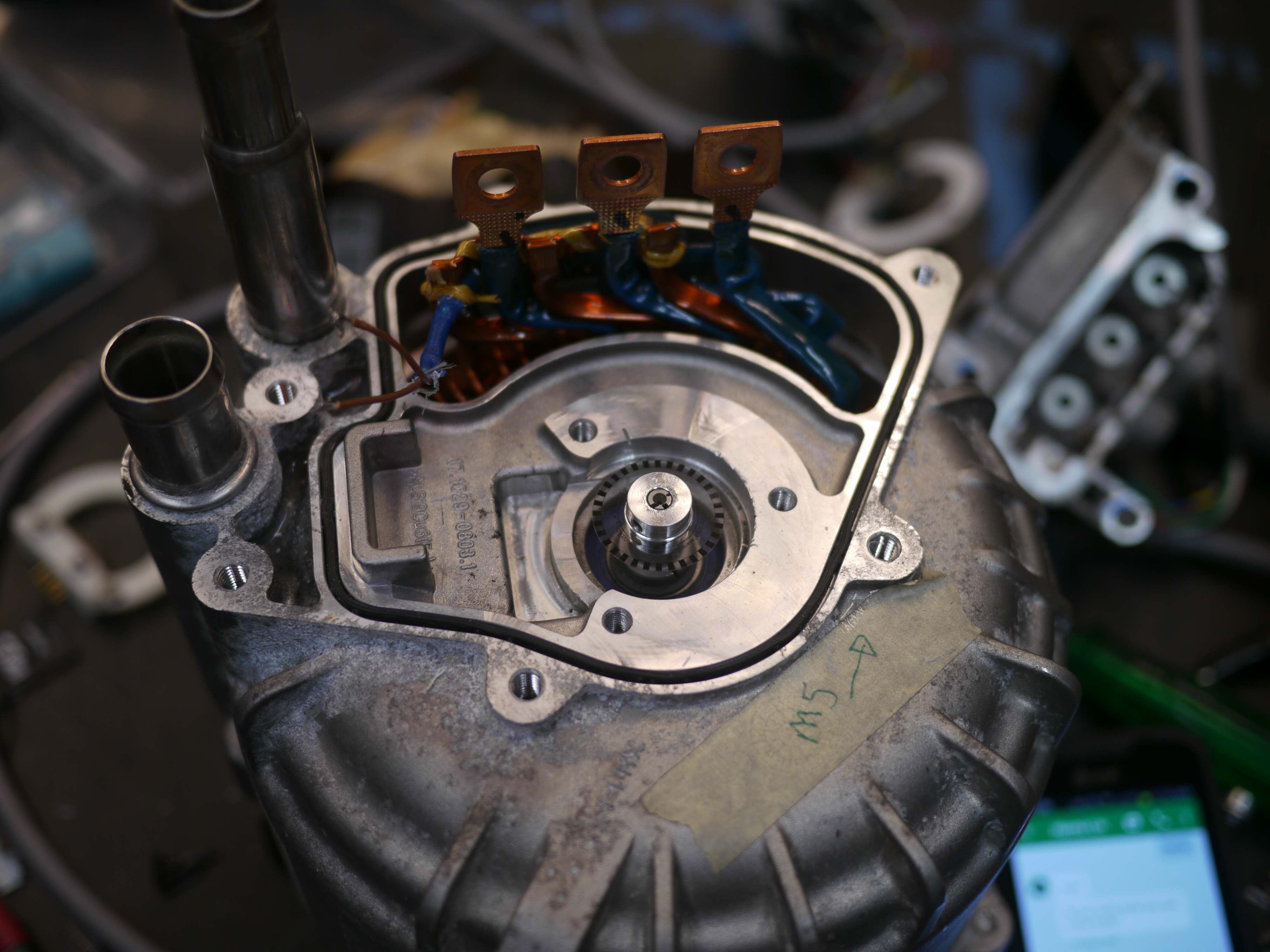
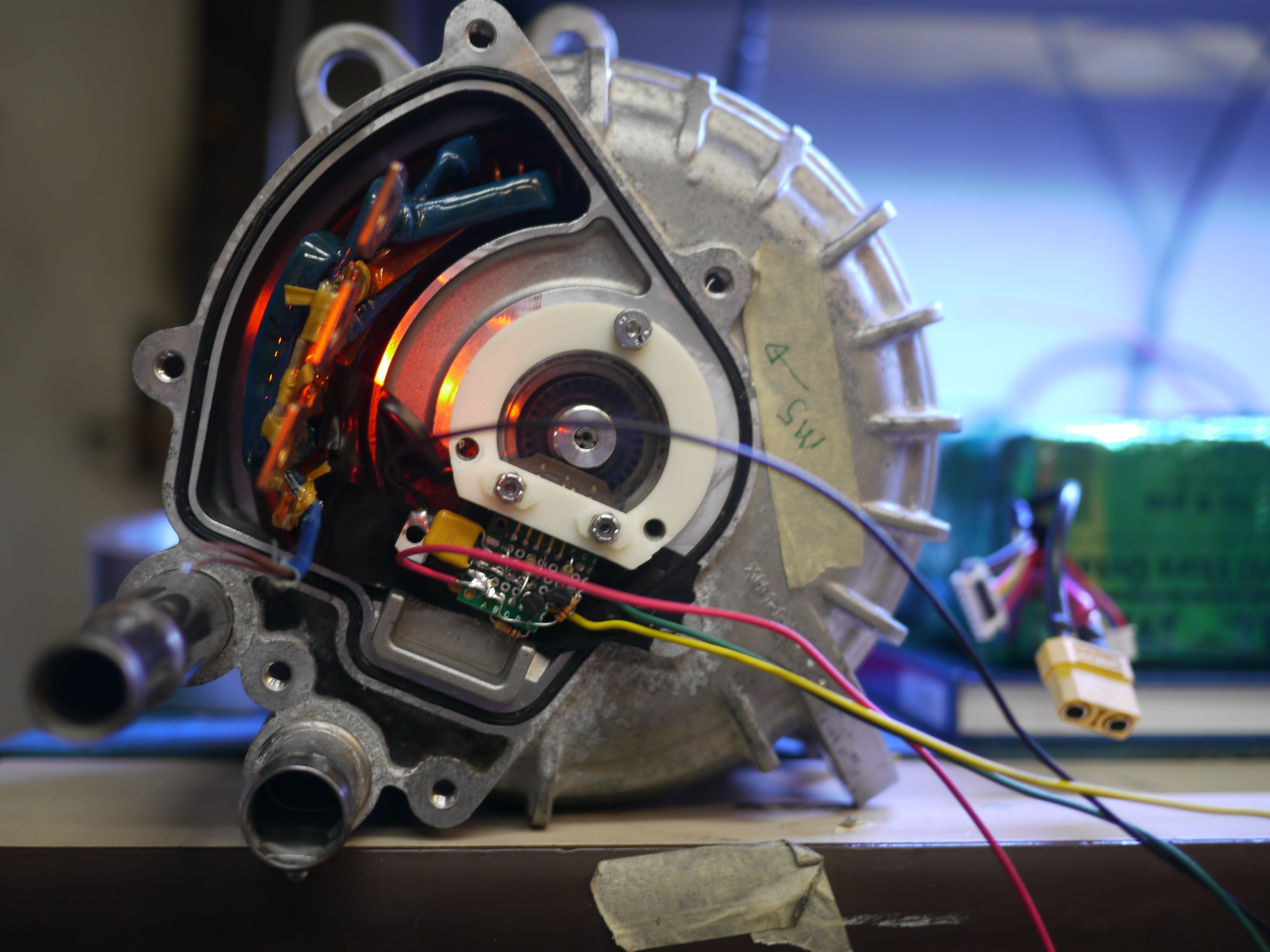
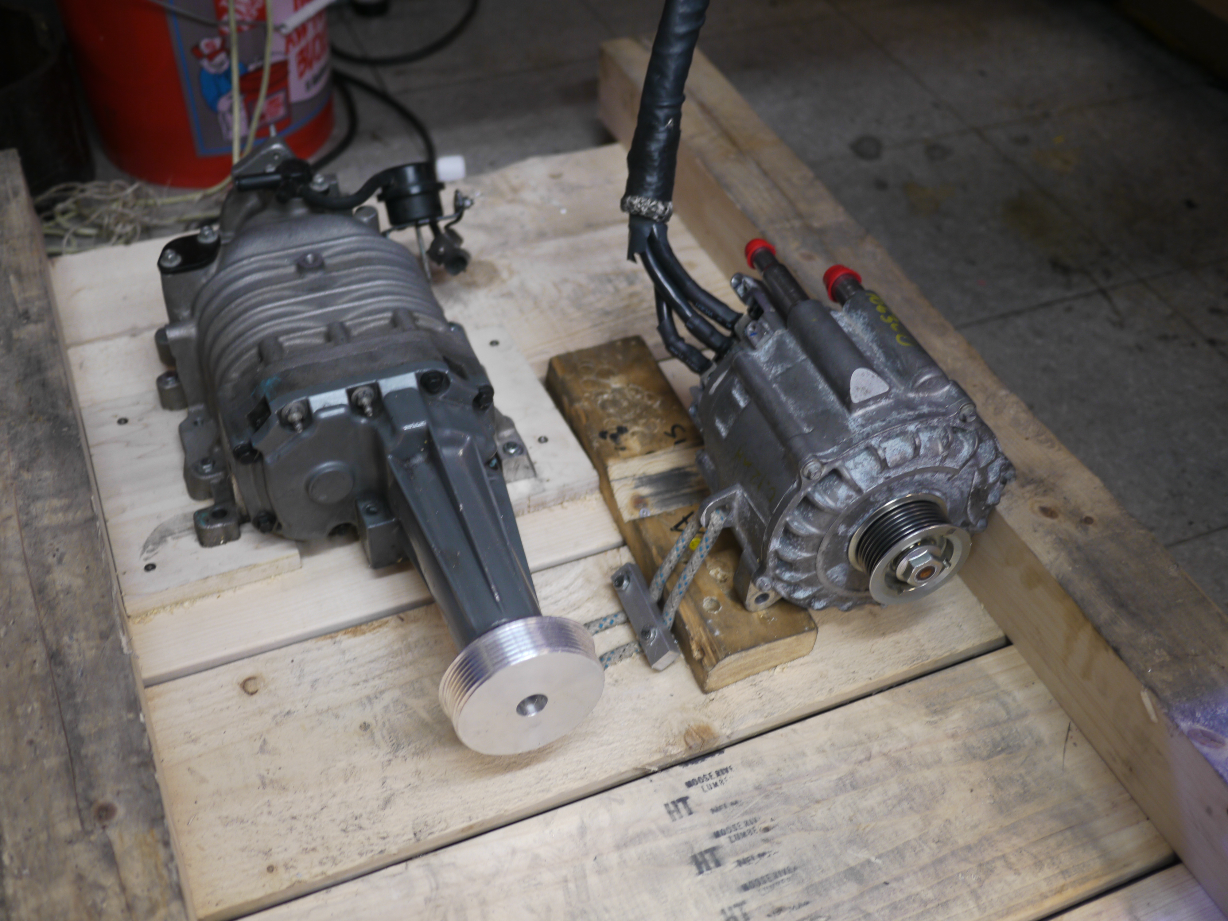
| Why only scoot when you can fly? The idea of waterskiing from the 8ft DANE-GER boat was postulated and after rumaging about, components were aquired to build a glorious 60-ish HP electric outboard. Last episode we painted and sealed the boat, and prior to that a 1kw dc outboard was born. Read on for details of using a hybrid Buick Lacrosse three phase induction motor, a 600A induction forklift controler and a pile of miscelaneous parts for creating the glorious ULTRA-OUTBOARD. |
 |
 |
| What? |
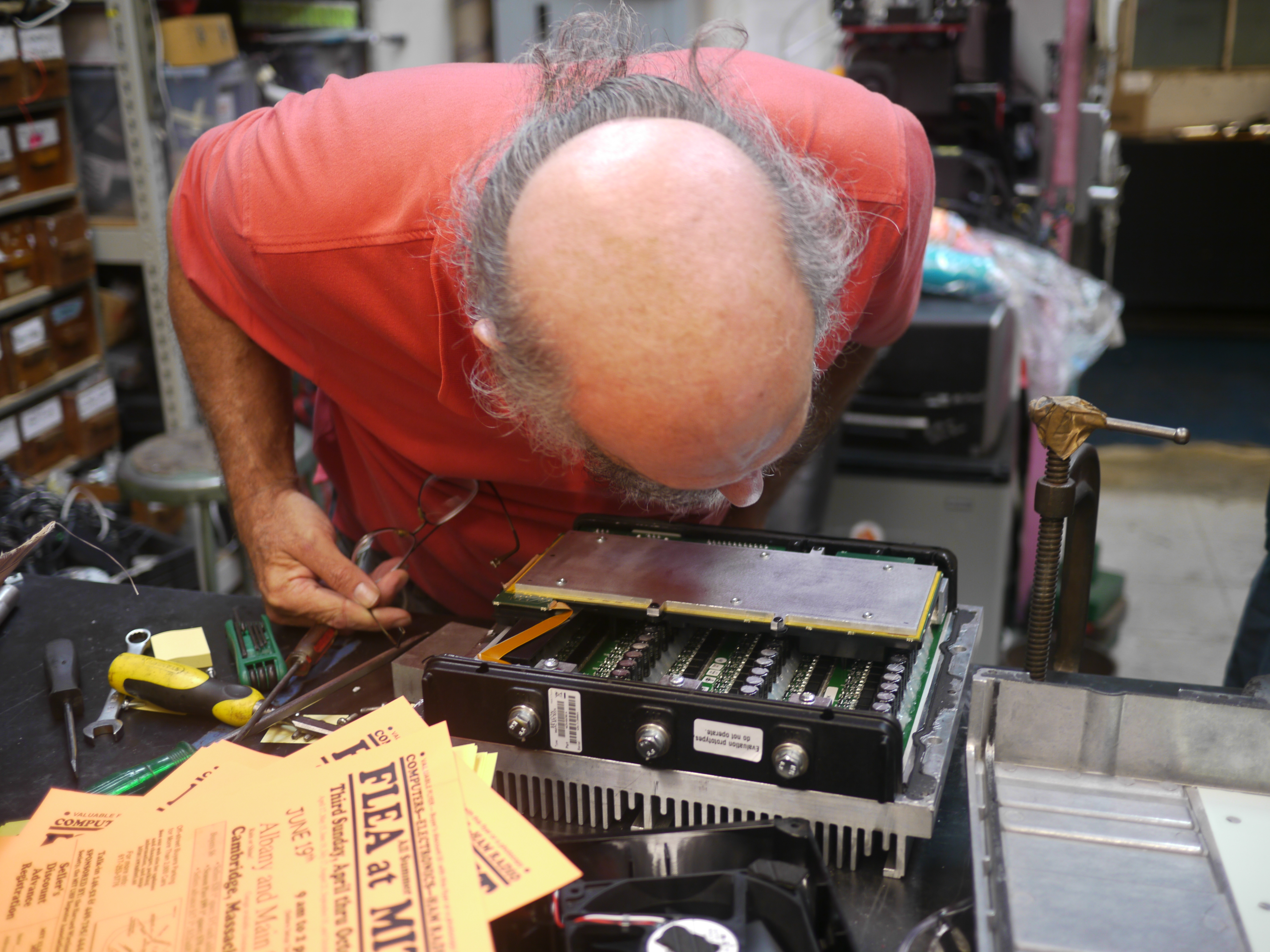
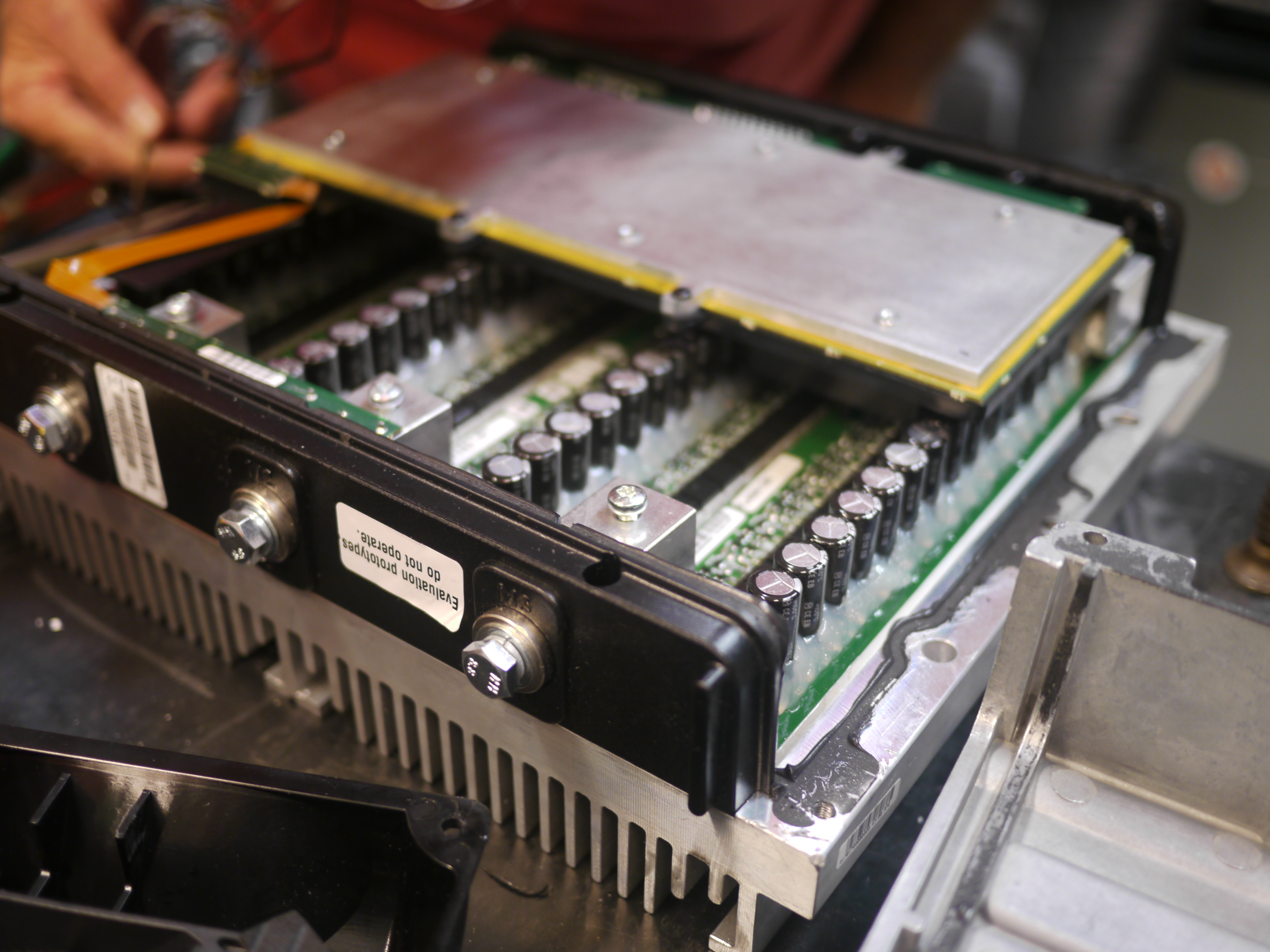
Removing
the Engine |
Electric Motor Adapter | Endurance Test | Conclusion | Image Directory |
PLEASE
NOTE THE BOAT AND OUTBOARD WERE STOLEN, IF YOU SEE IT PLEASE CONTACT ME
IMMEDIATELY
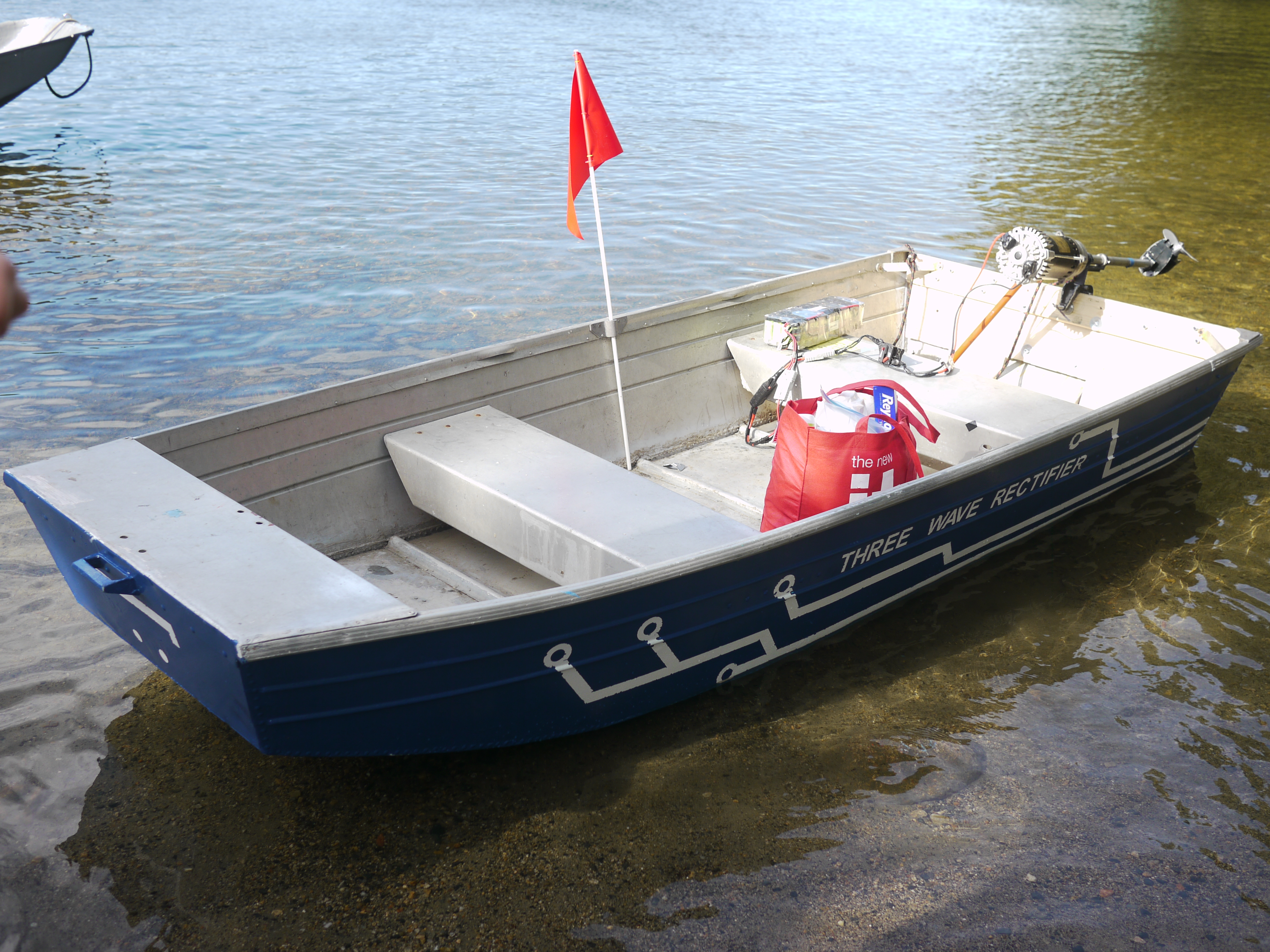
| The Great ULTRA ELECRIC BOAT ADVENTURE Remember the 8ft aluminum boat from last episode? [link] Imagine waterskiing behind it. 48 KW (60HP) OF DELICIOUS 3 PHASE in an outboard-shaped format attached to a small boat. |  |
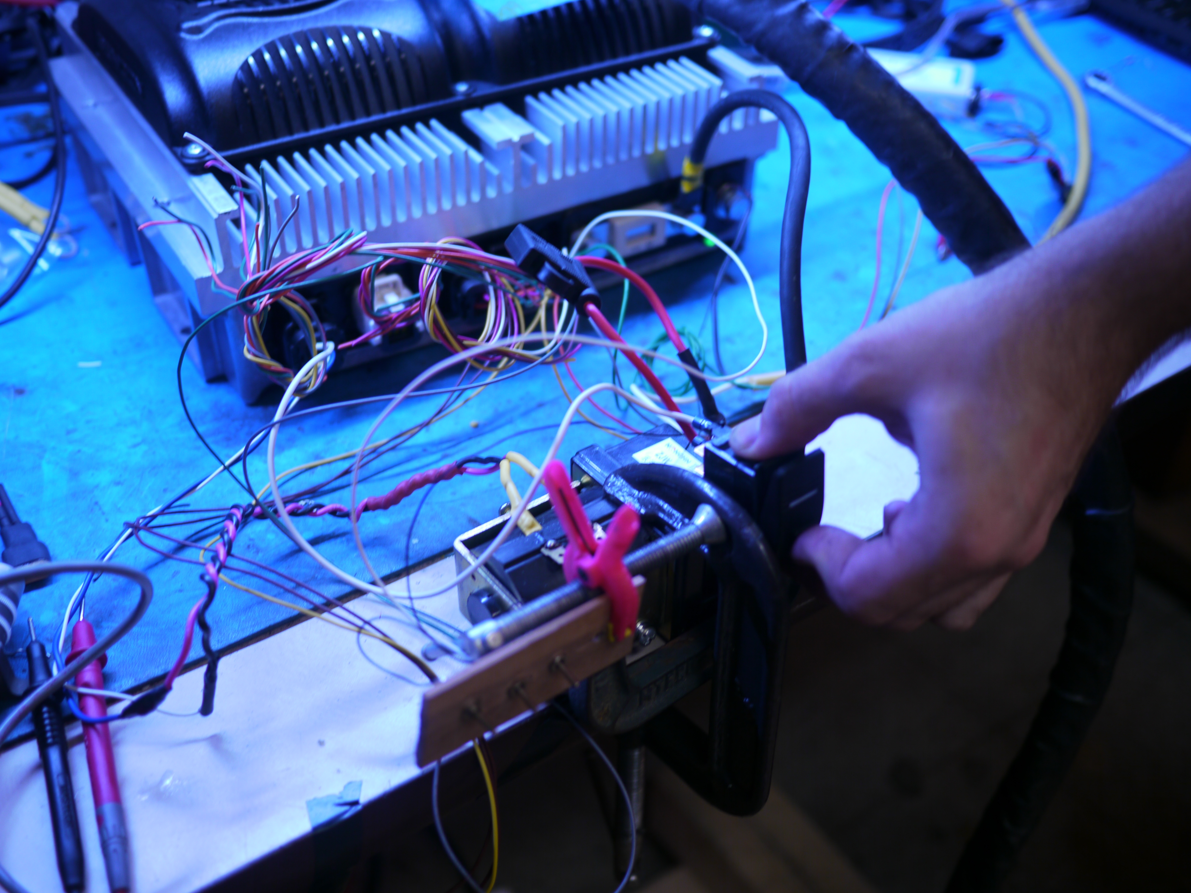
| The
Innagural test of the ultra thruster WHAT CAN DO 600A at 80V do? HYPOTHETICALLY ENABLE AN 8FT BOAT TO SUPPORT WATERSKIIERS. THINK ABOUT IT 48 KW PEAK INTO WATER. GLORIOUS, GLORIOUS SCIENCE AHEAD. |
| Why not just run a gasoline outboard? |
| Second hand gasoline outboards
are actually fairly easy to come by, there are some
disadvantages: * Not permissible in certain lakes / resivours (generally there are no rules for electric propulsion, namely because there arent any high power options) * Greater than 3hp gets fairly expensive quickly. A 10hp functional (used) outboard start at $300 in the Western Mass Area. Transom mounts for large engines get fairly heavy as well (to support large engine)s. One of the main reasons for looking at electric was the first issue: Gasoline engines werent permitted, electric craft? Goto town. |


| From the sponsors: |
|
|
|
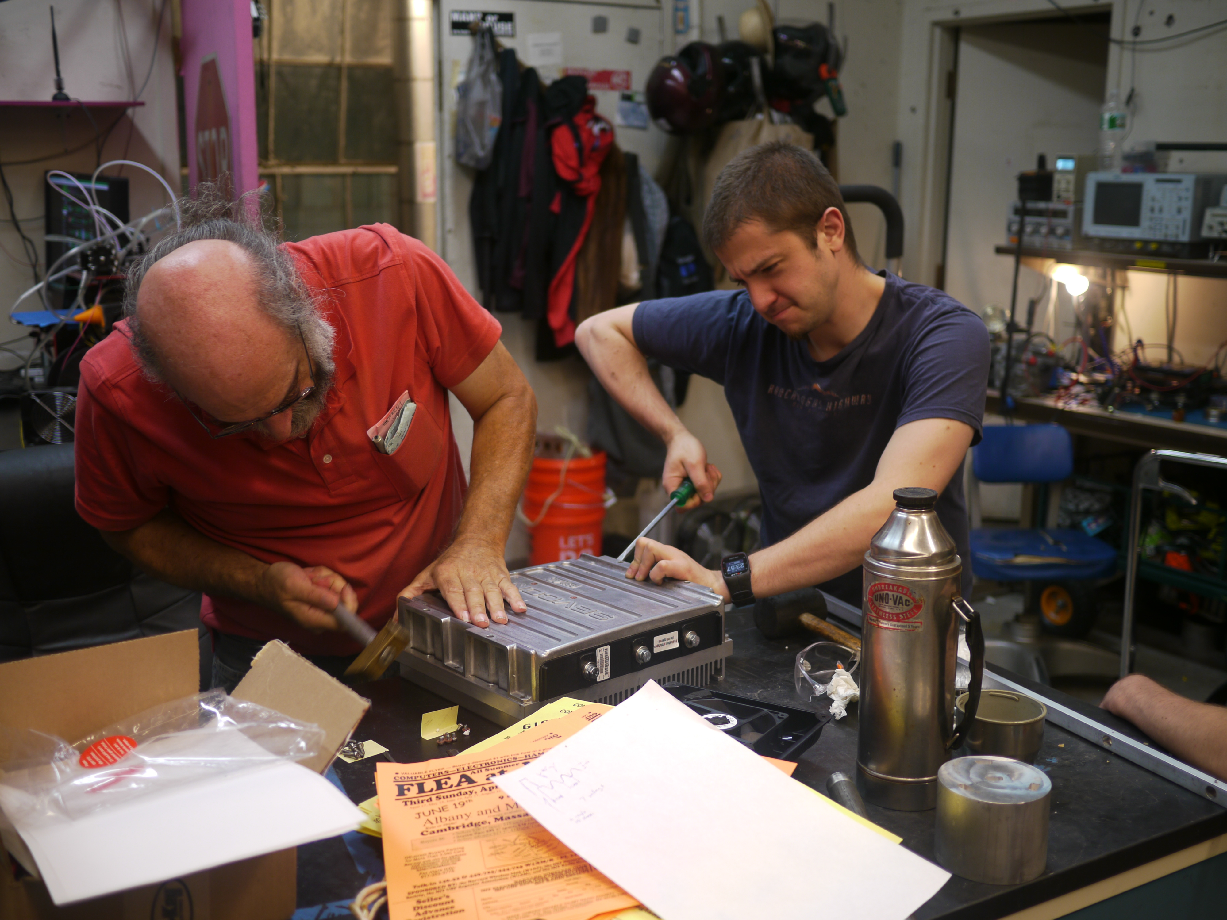
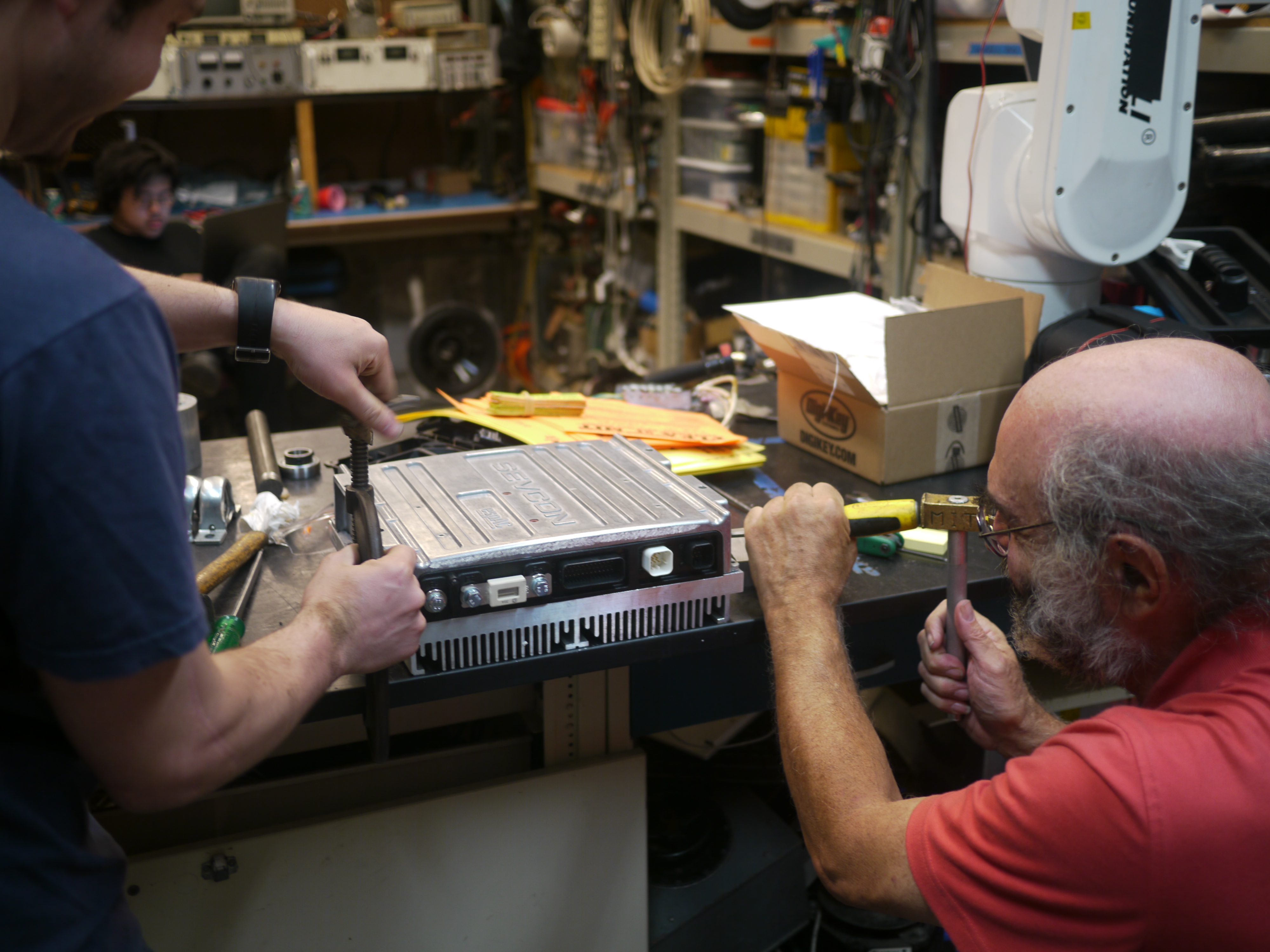
| Lets build pseudo-outboard mechanicals in an evening | ||
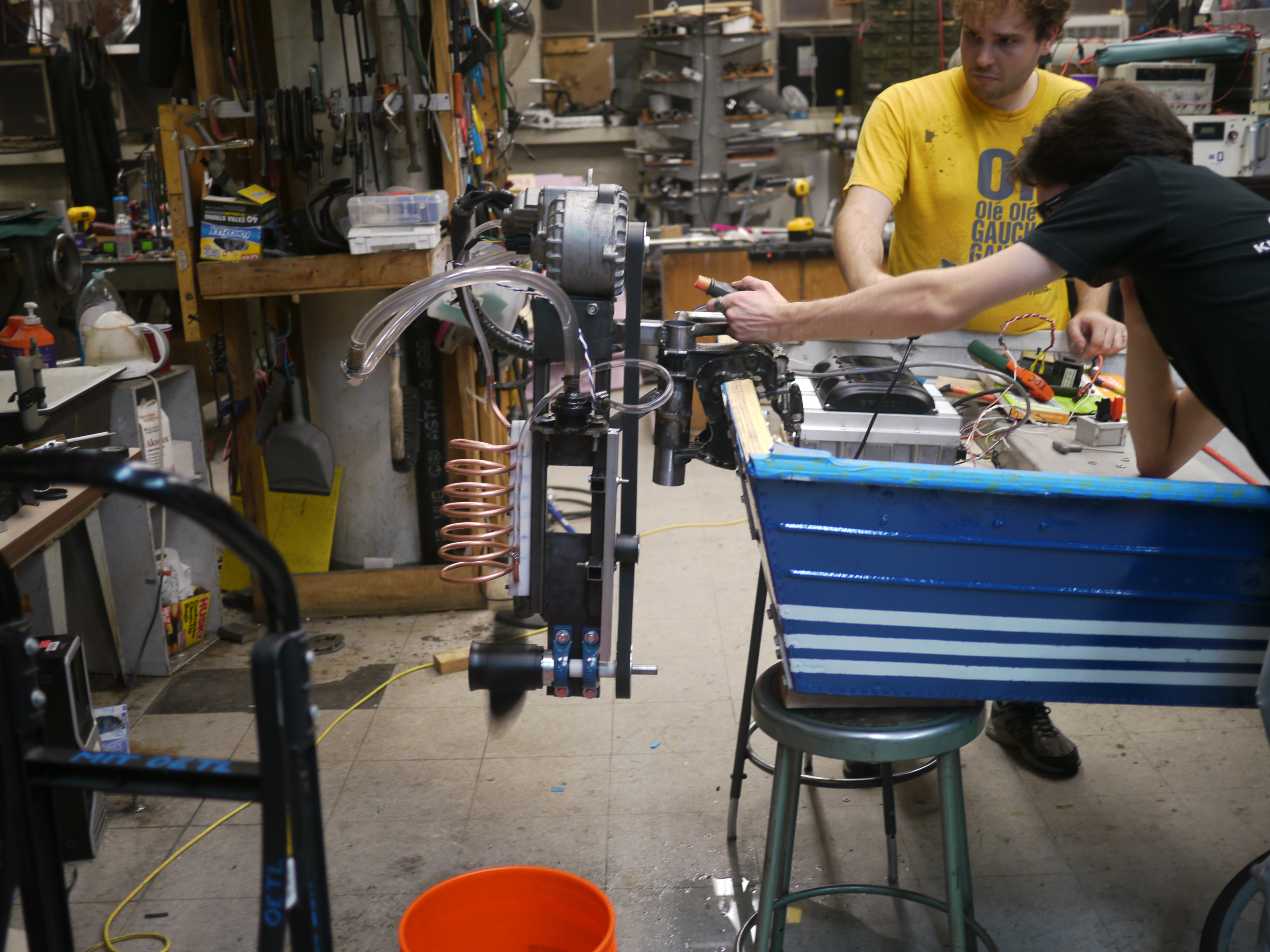
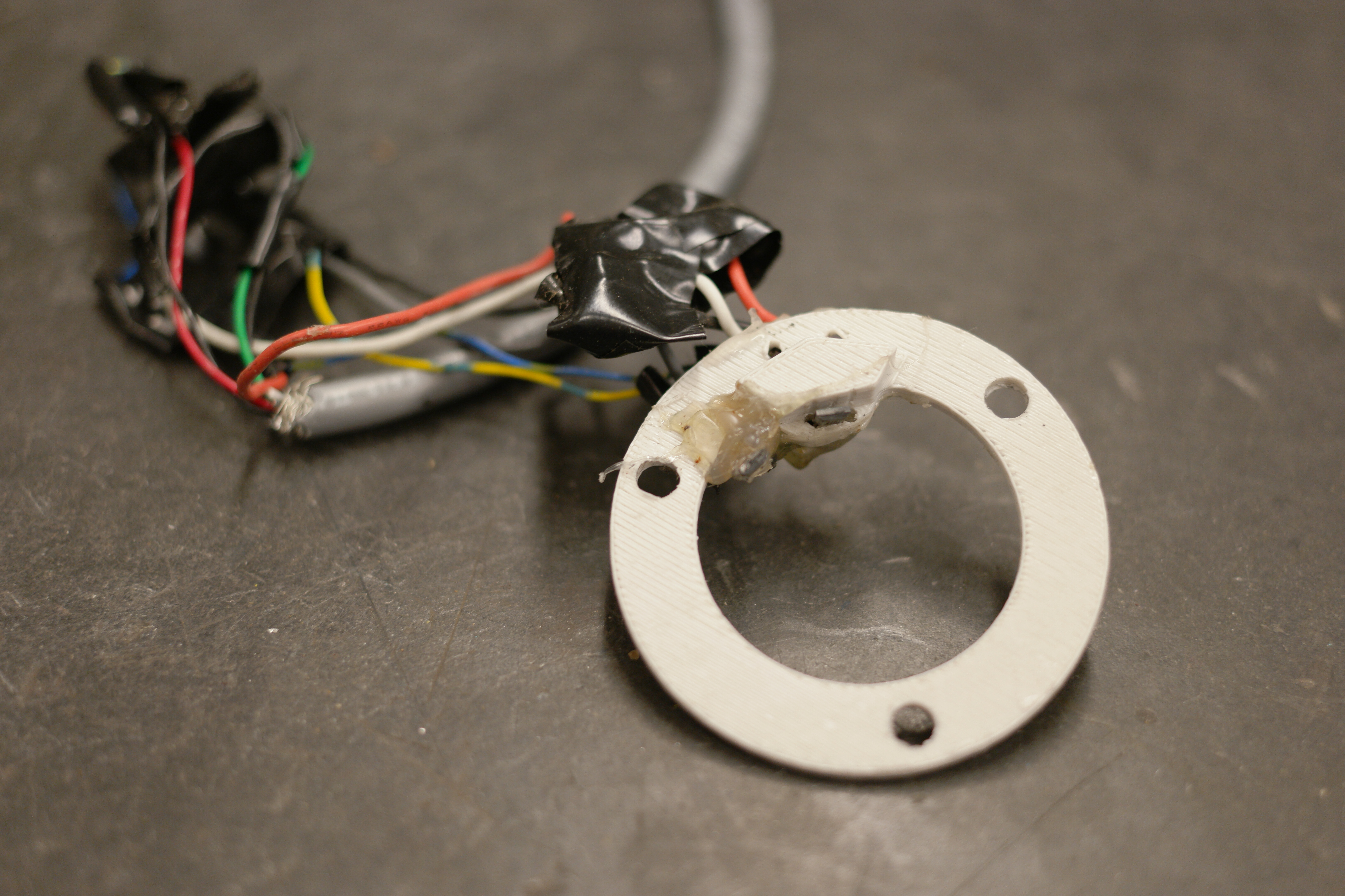
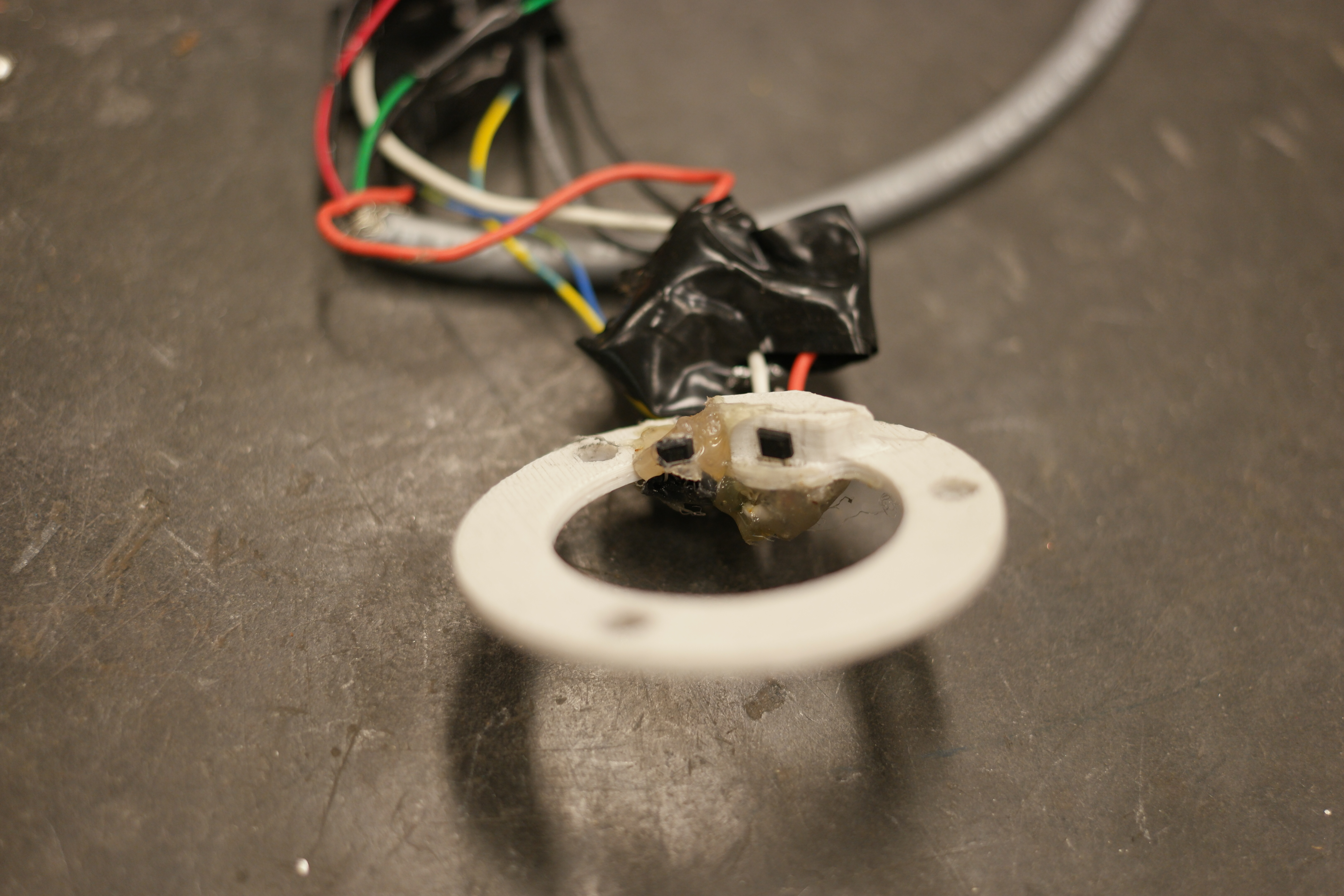
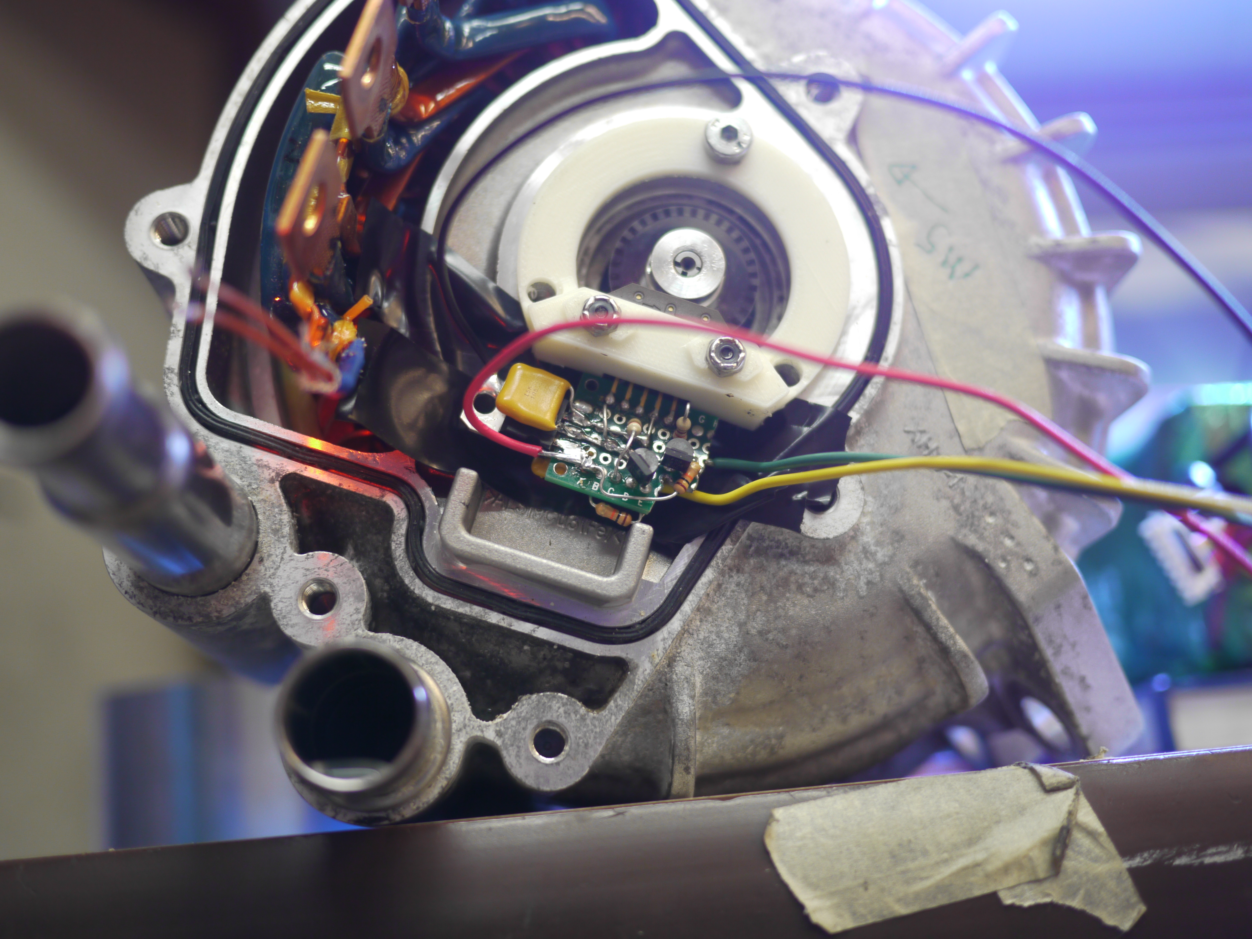
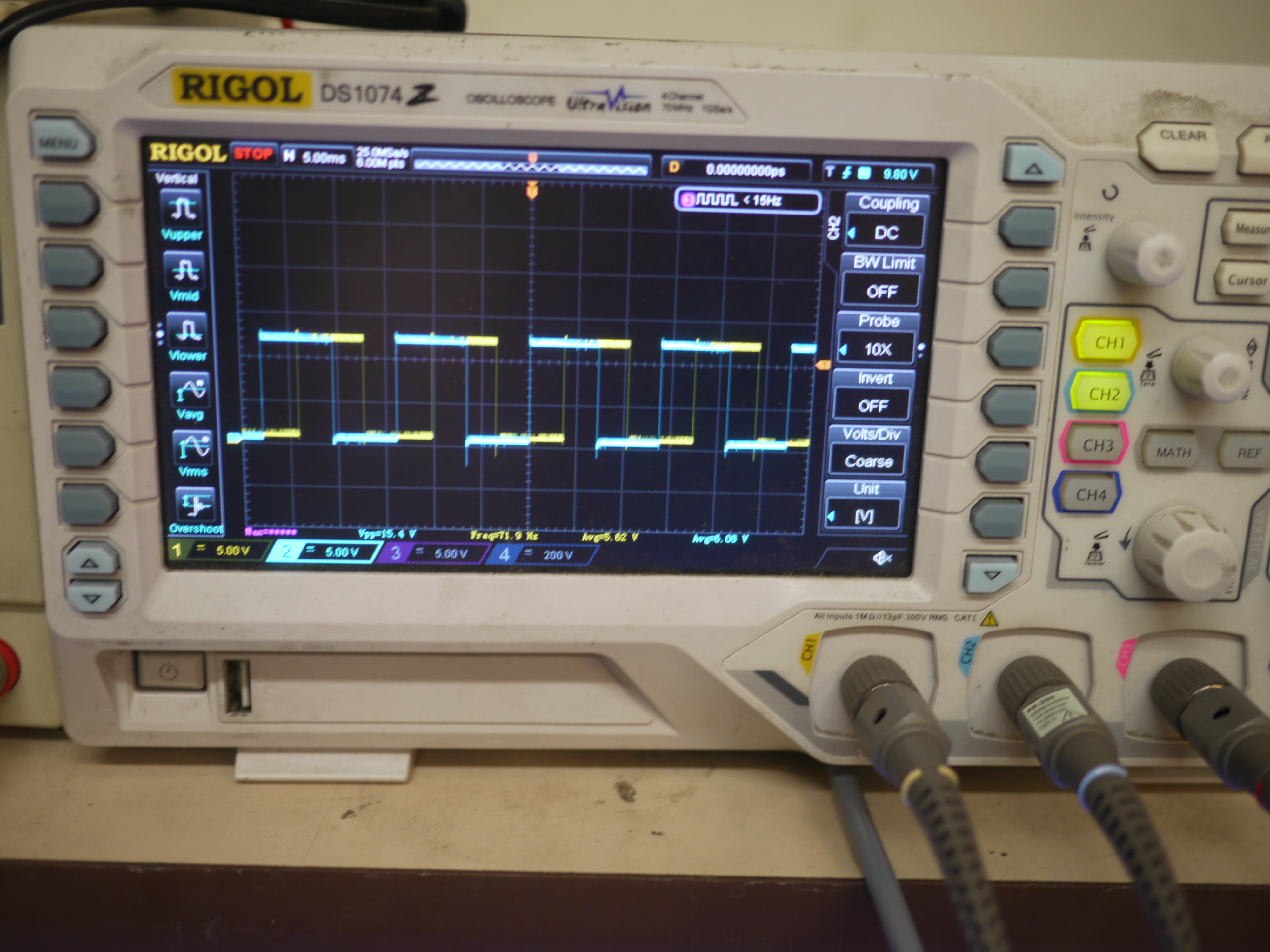
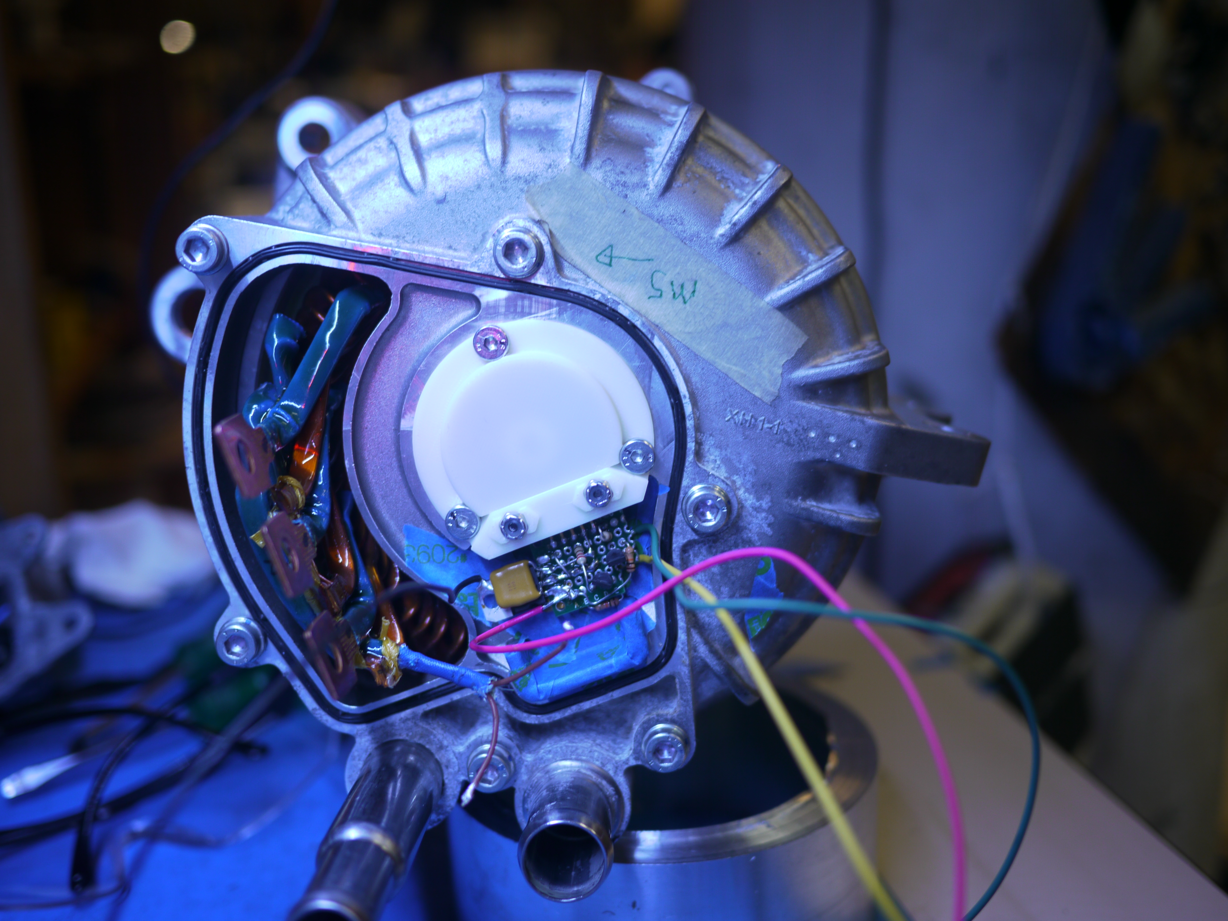
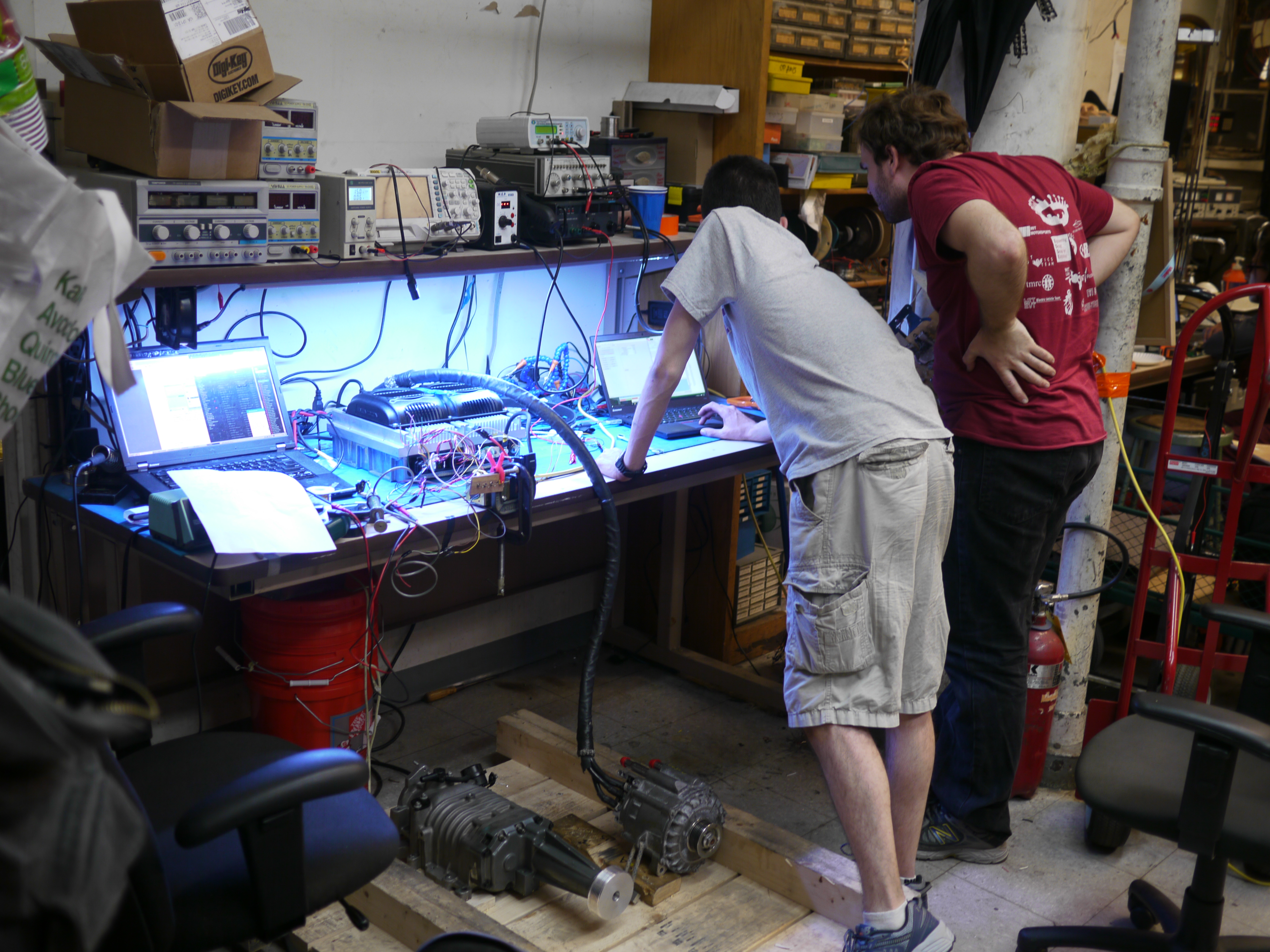
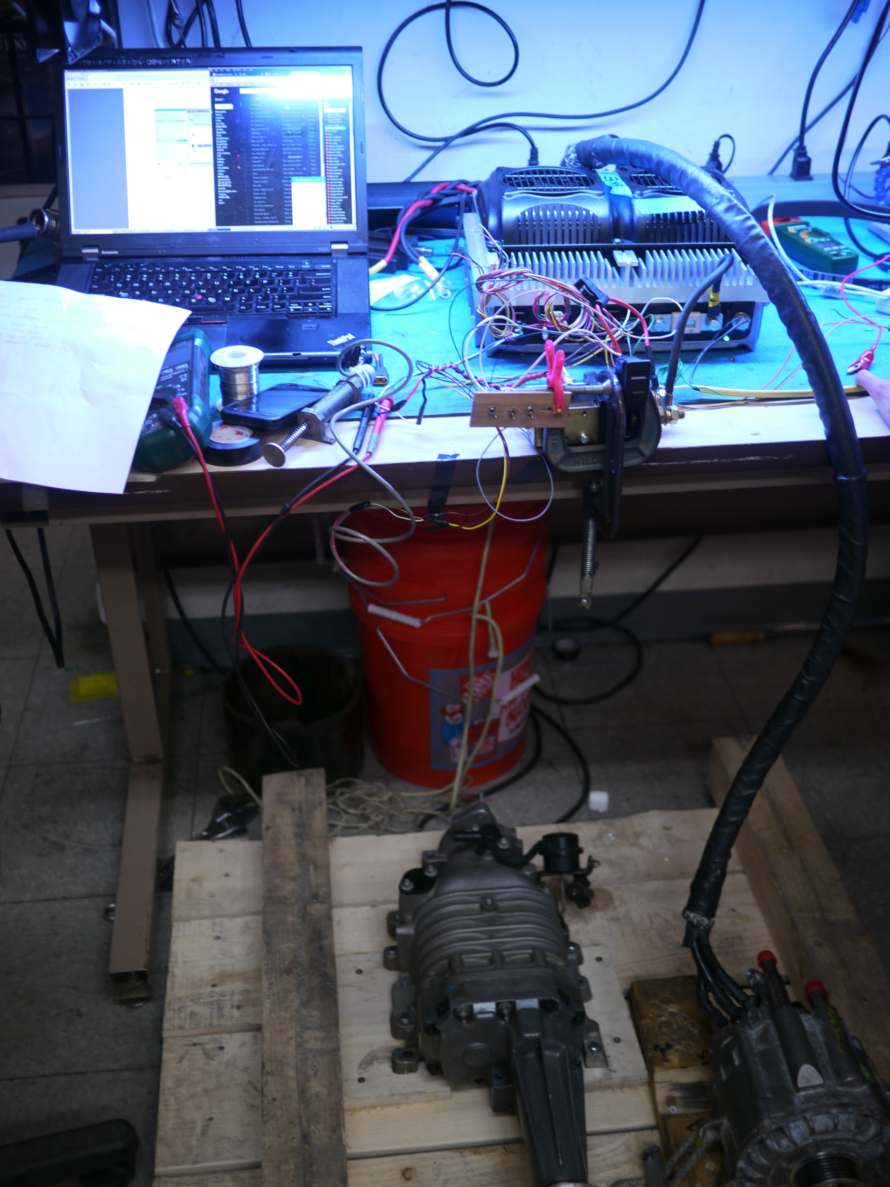
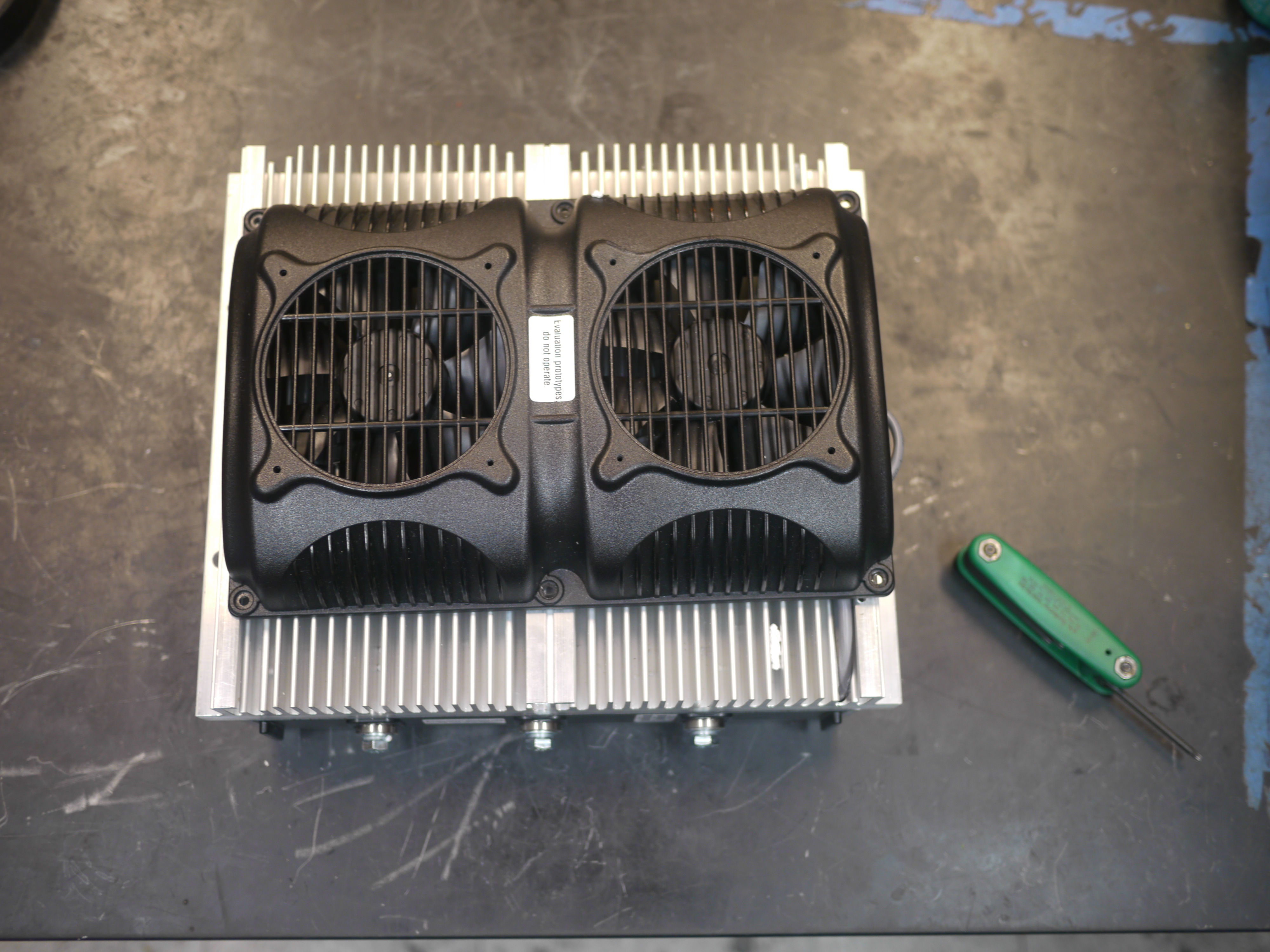
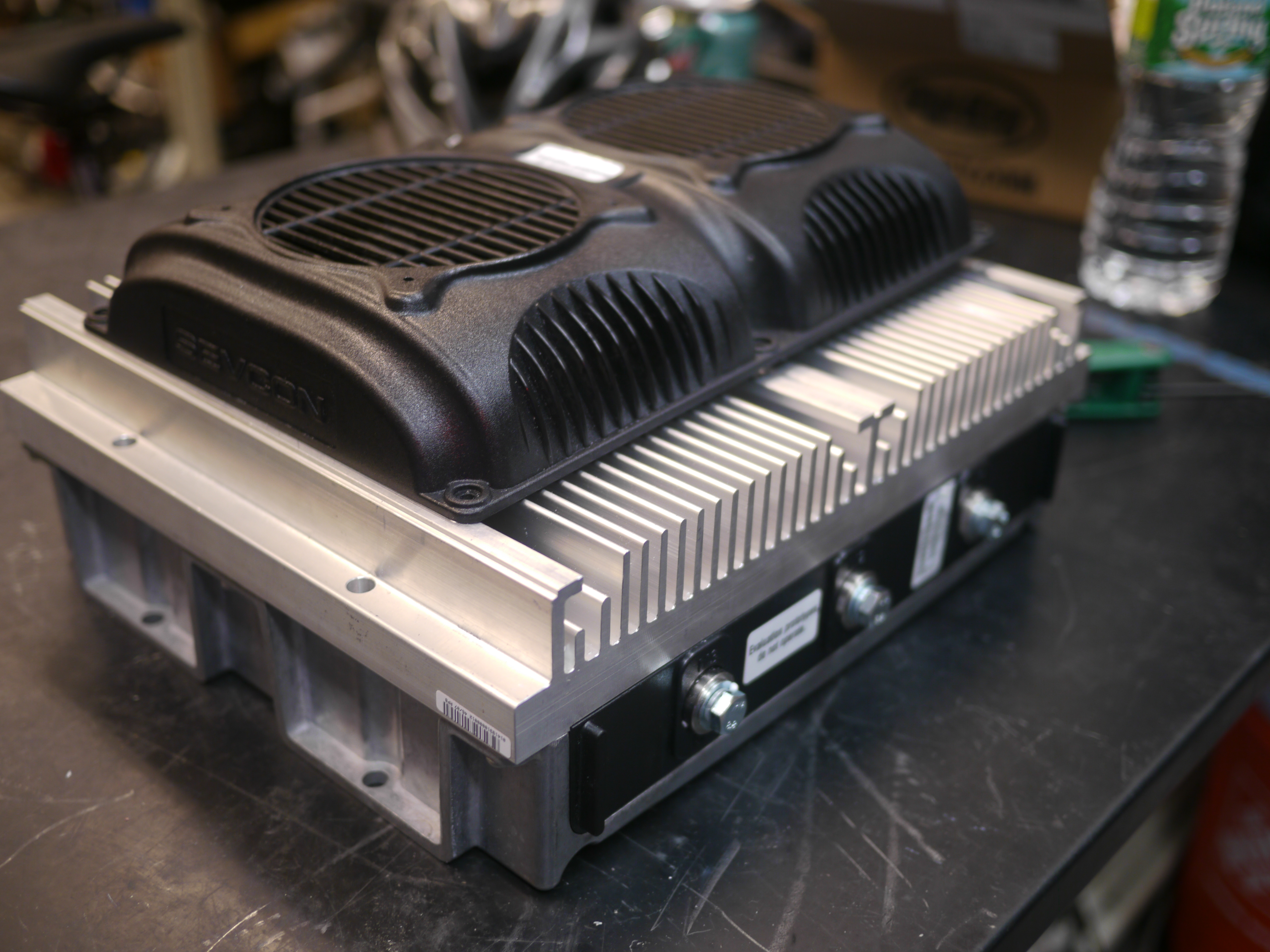
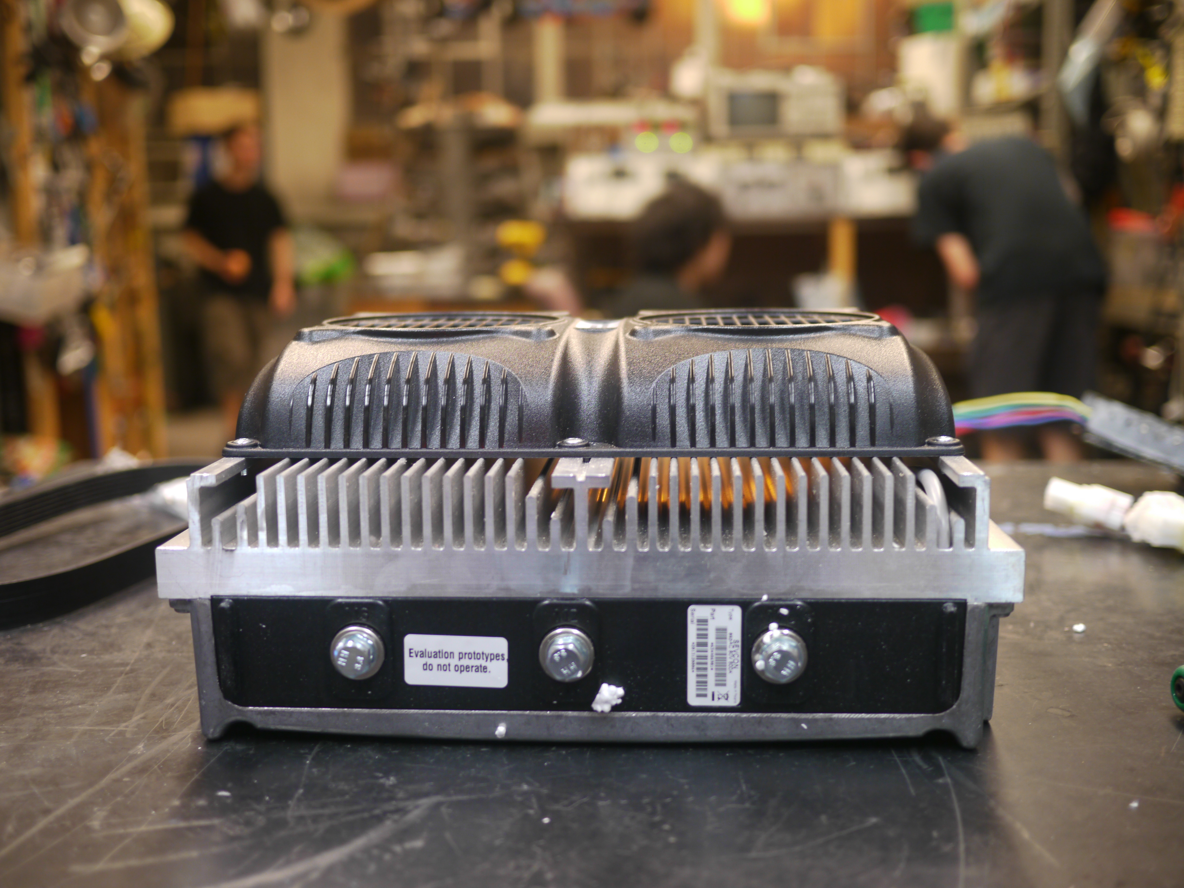
| With the motor controller responding, the rotor position feedback loop tuned and a procedure for satsifying all the interlocks, we now needed, er, a thing that the motor could mount to and apply propulsion to the water with. An outboard. Should be simple right??? | ||
| PROPS I was gifted Two very excellent boat props from the ever-excellent Ted. The prop is huge and intended for a ~35hp boat. EXCELLENT. The prop-mate is a spline, and has a locating feature to allow it to transfer torque over a spline, be retained against a pitched locating feature, retained by a nut and then locked in place with a carter pin, or the like. Now to find the mate to this, er, beauty. . | 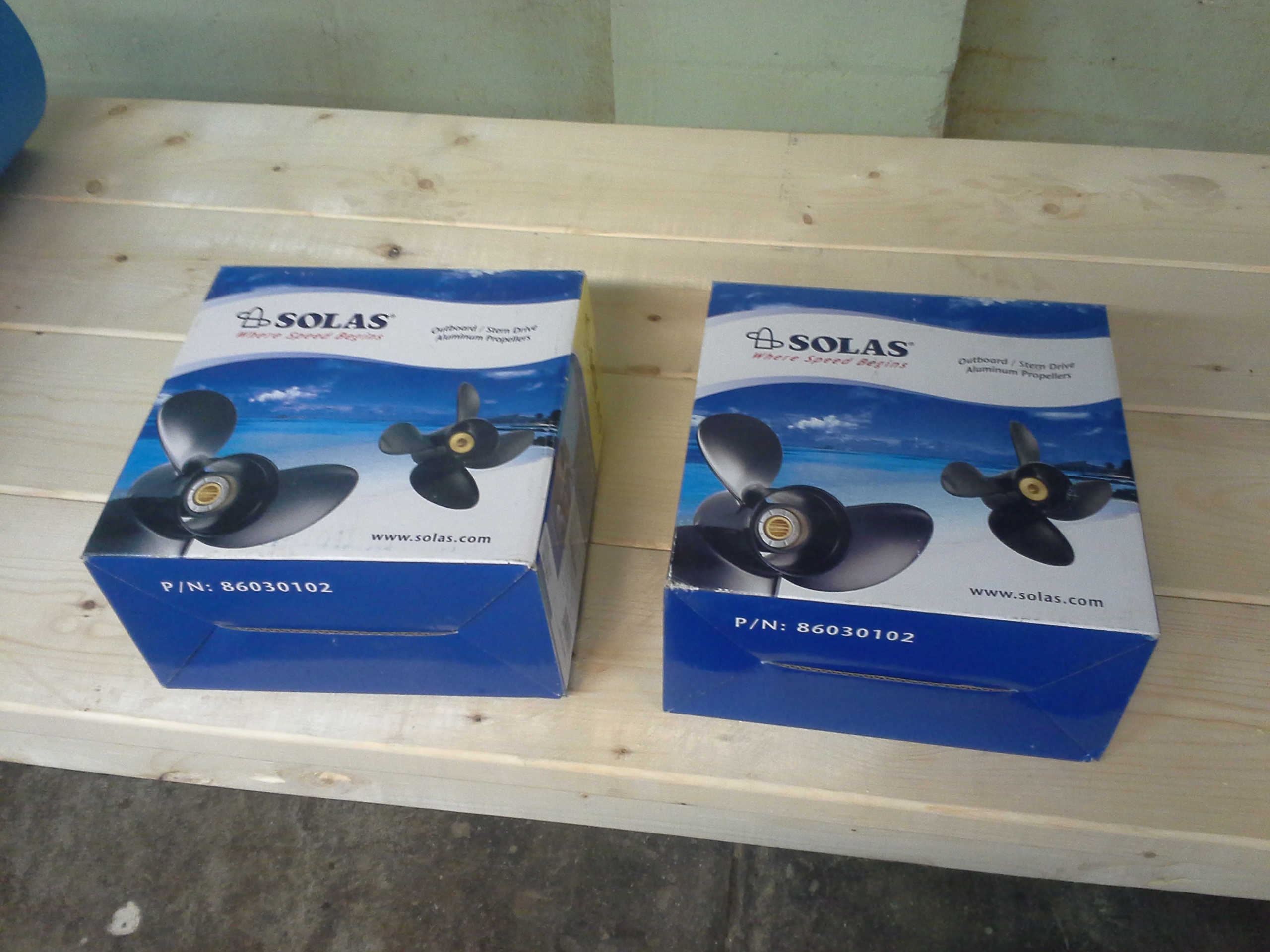 | 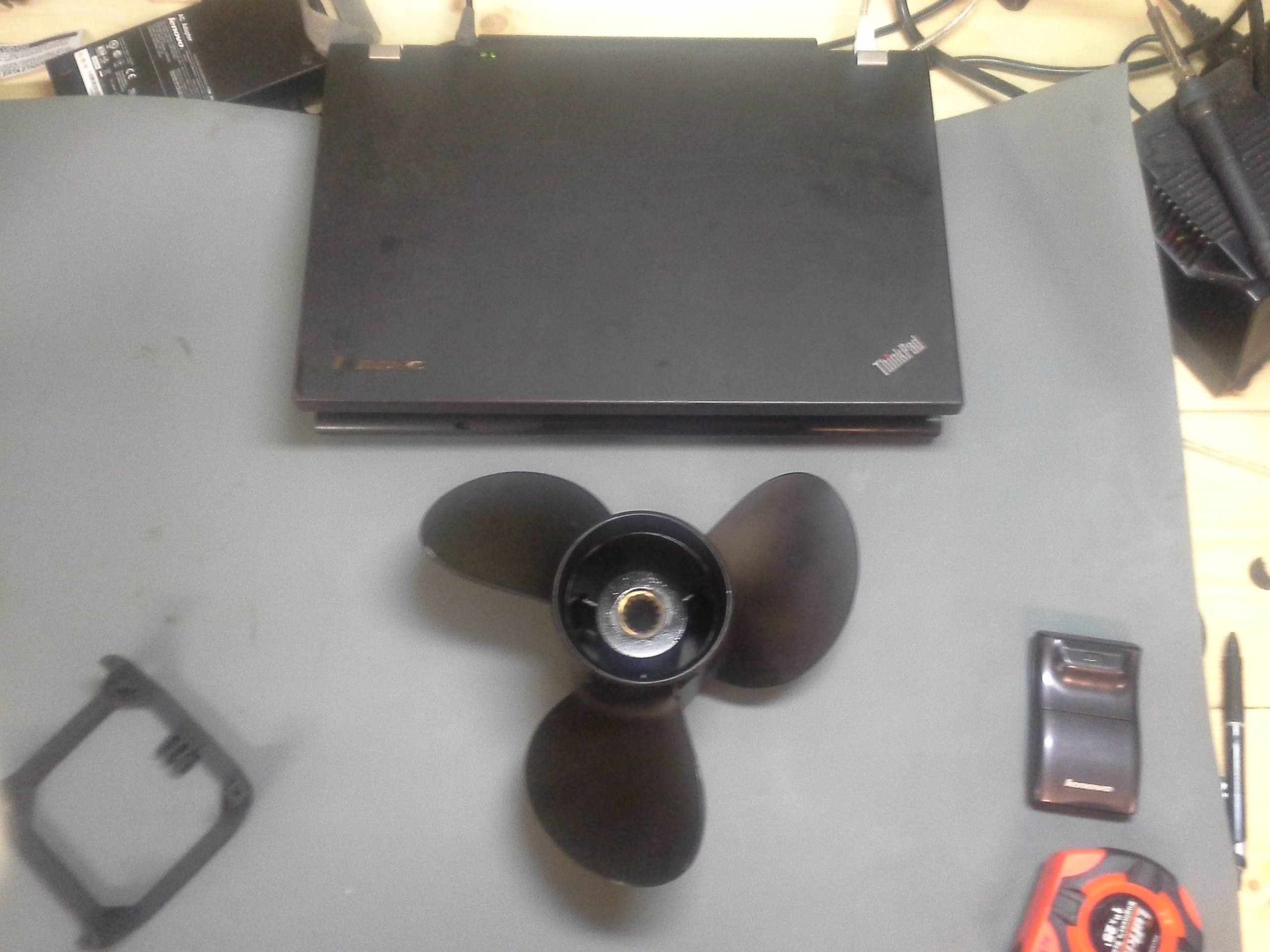 |
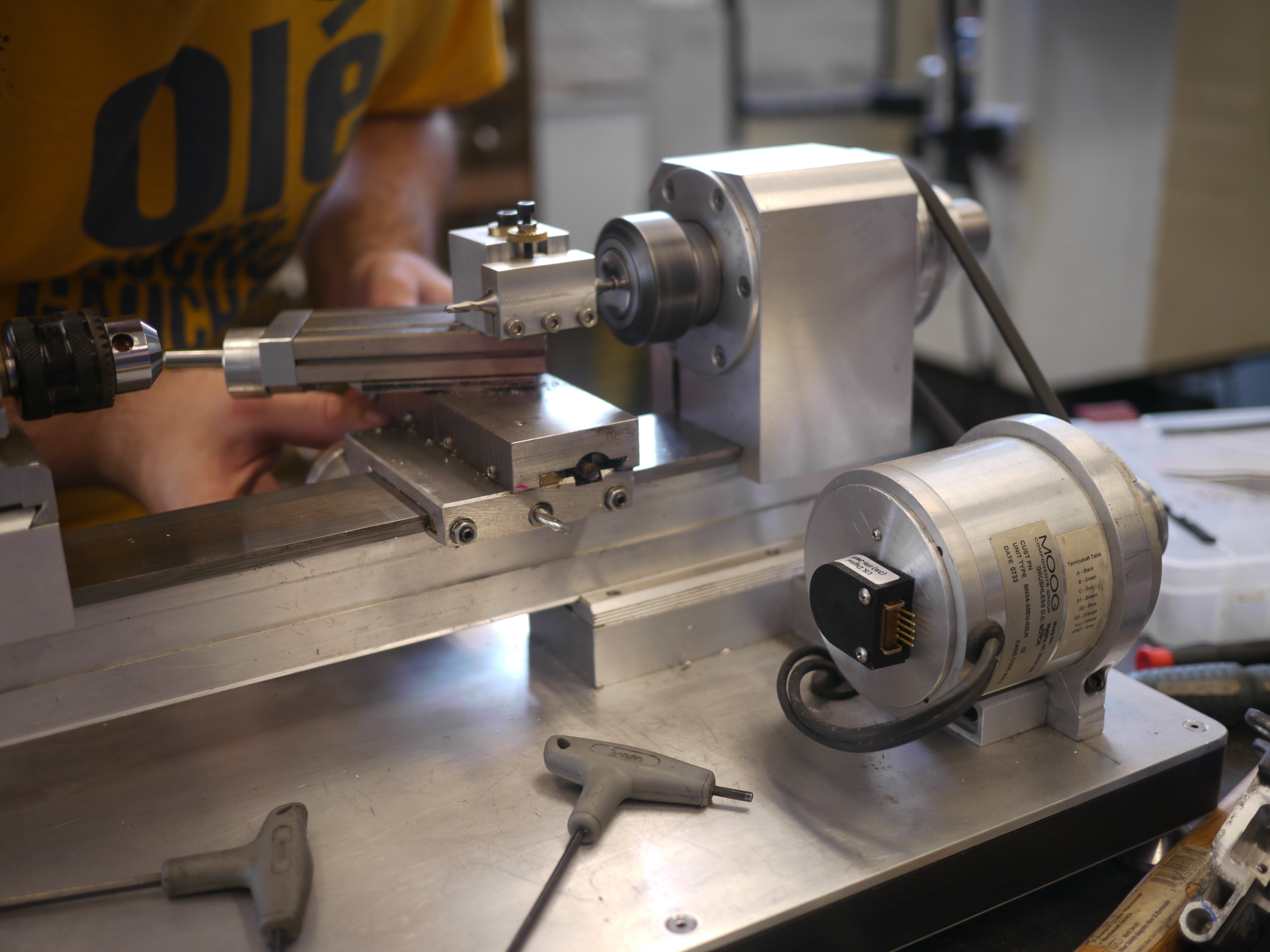
| SPLINE MEET SHAFT A very long arduous ebay hunt ensued and a few days later, A SHAFT WAS FOUND. IT FIT. SAM, THE EVER EXCELLENT, located this part. I didnt need to make a shaper tool or bludgeon my fingers with a j-head shaper attachment for a bridgeport or however these things are made. | 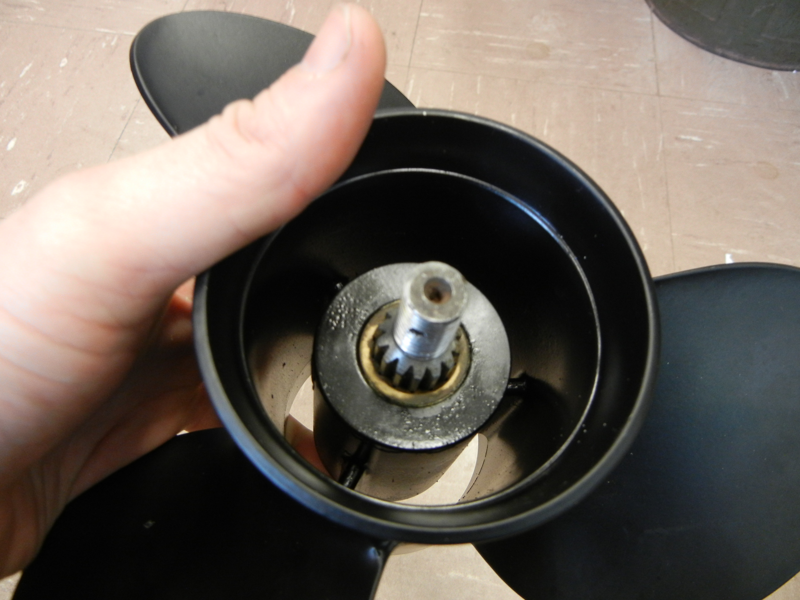 | 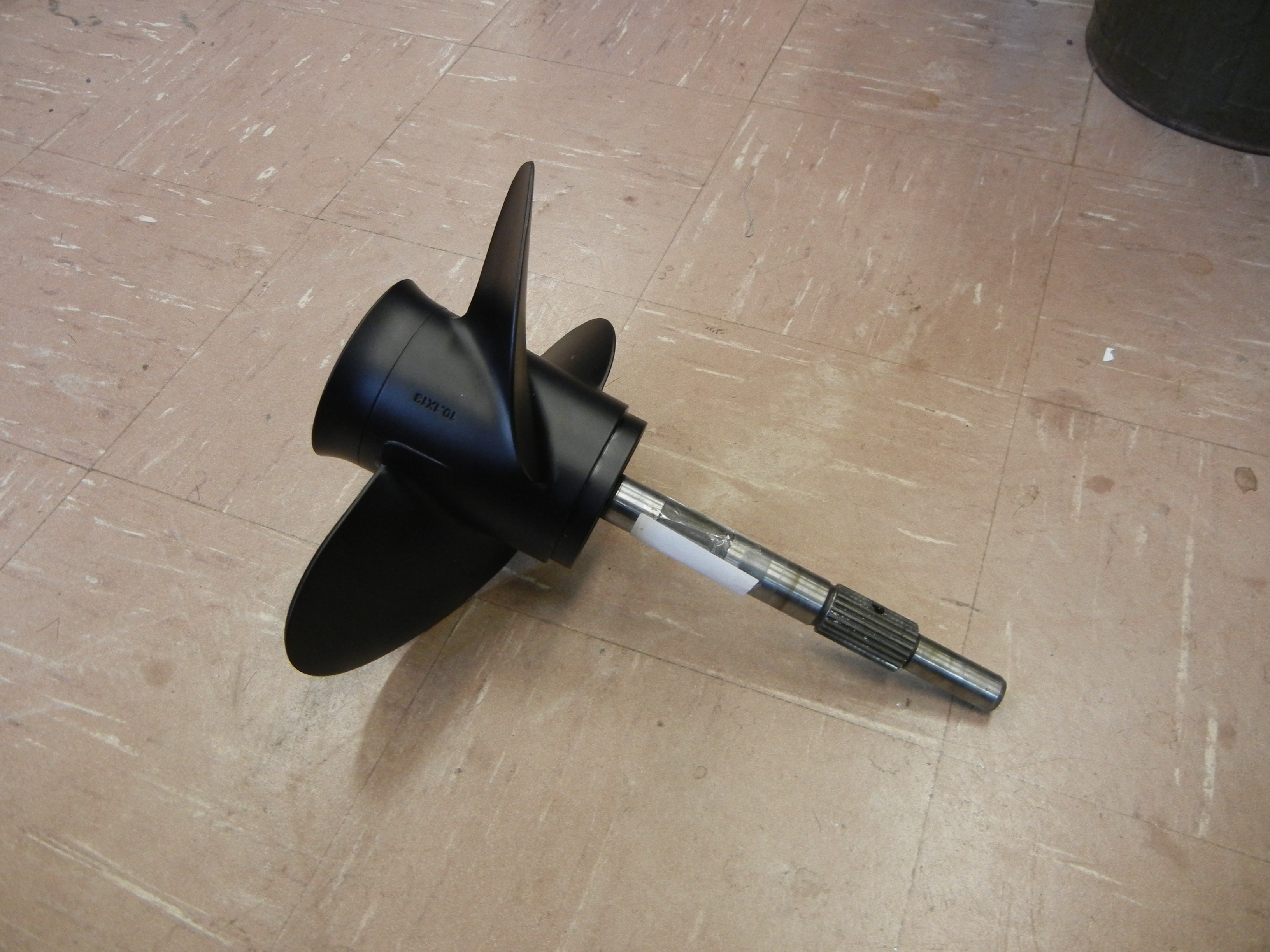 |
| WAIT DANE, YOU'RE NOT DOING WHAT I THINK YOU'RE DOING ARE YOU? Serpentine belt into a submerged | ||
| The Great outdoors: A test of
great science |
||
| With the recently 'completed' craft, myself Peter, Sam, Birkel, Frederick, Ciarian, Jume, Austin and the remainder of miters headed out to the beautiful western waters. | 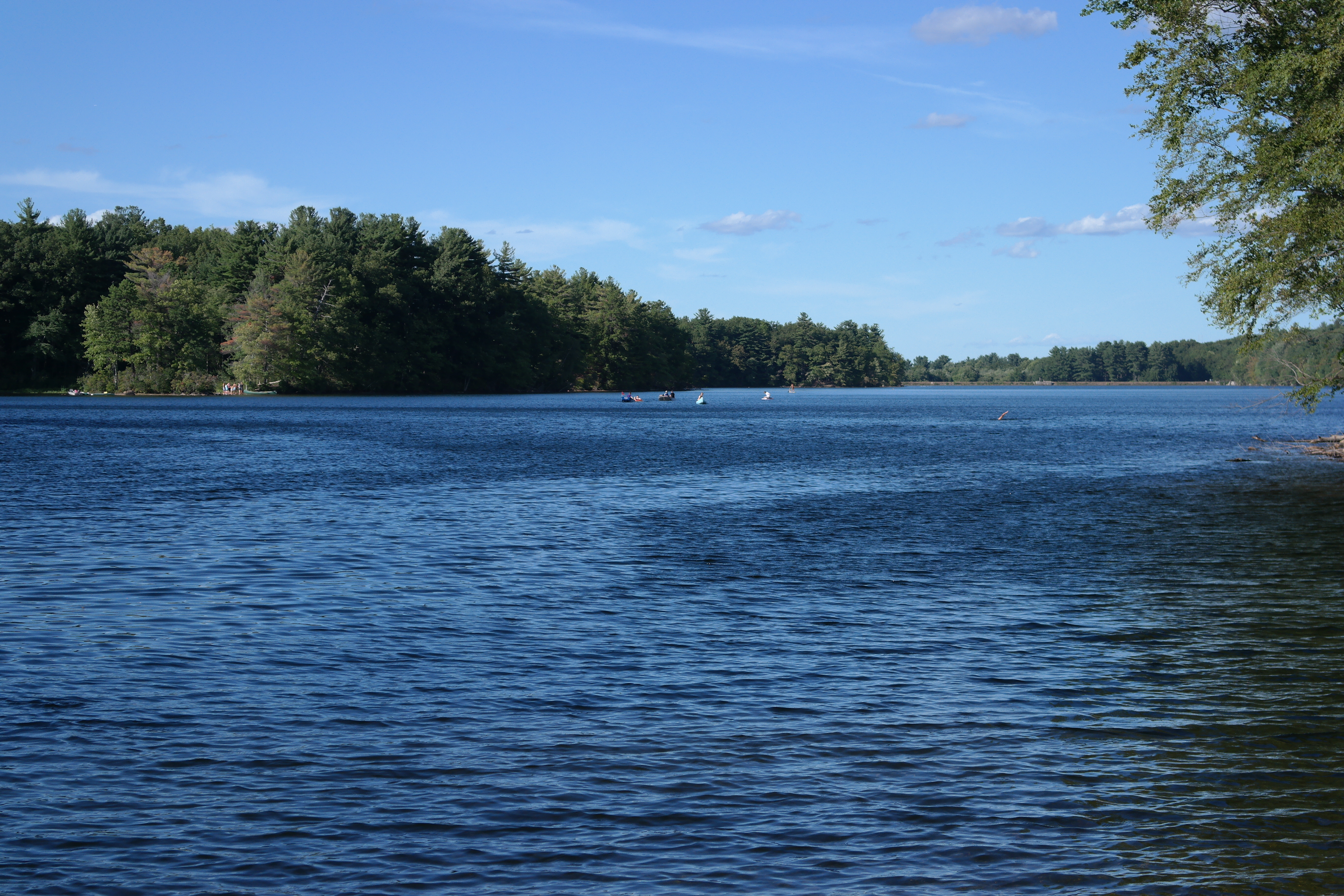 |
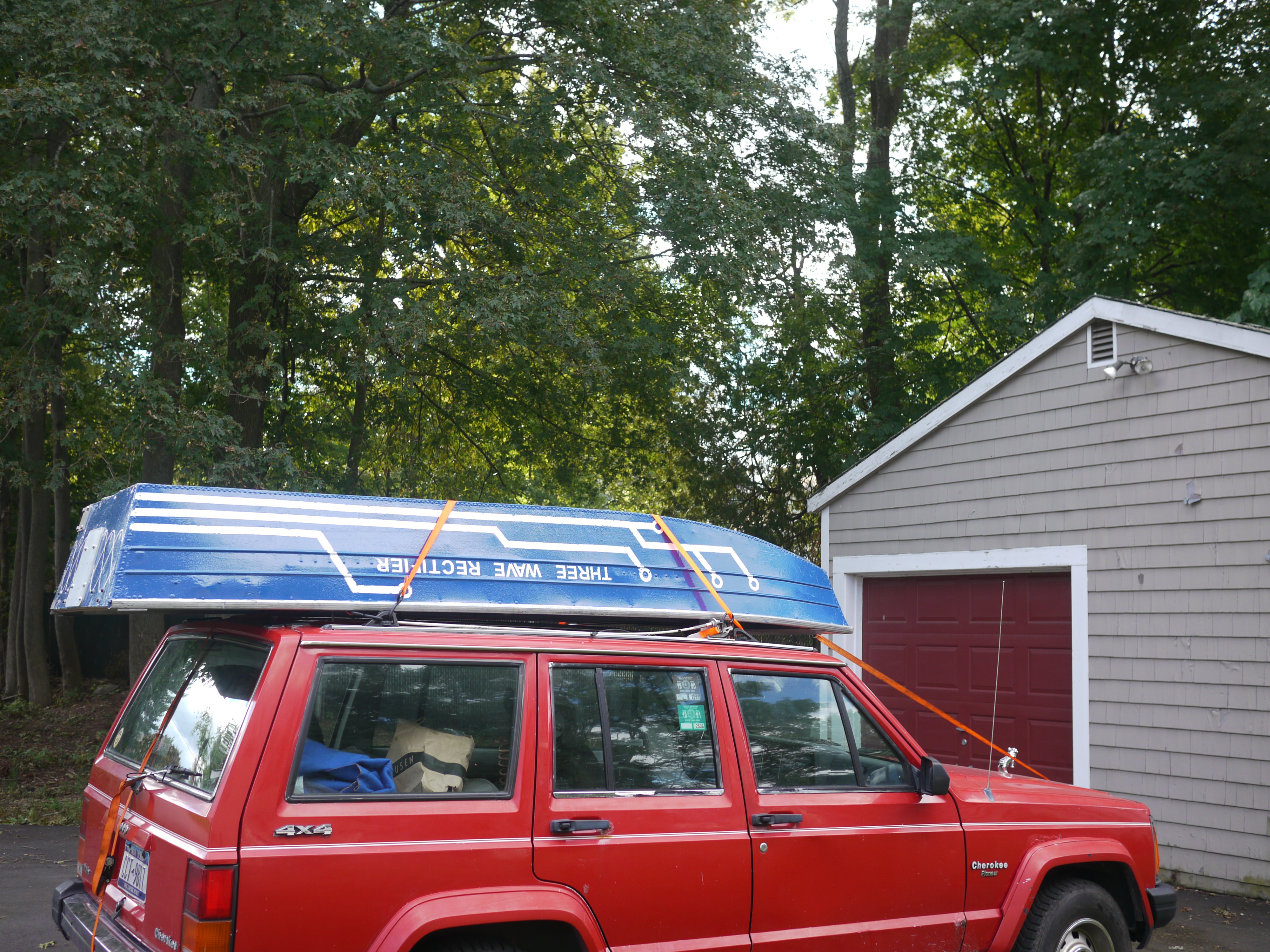 |
| The painted boat came out great and really got a chance to shine on its 'maiden' voyage. More about the painting and restoration process for the aluminum hull is available here. | 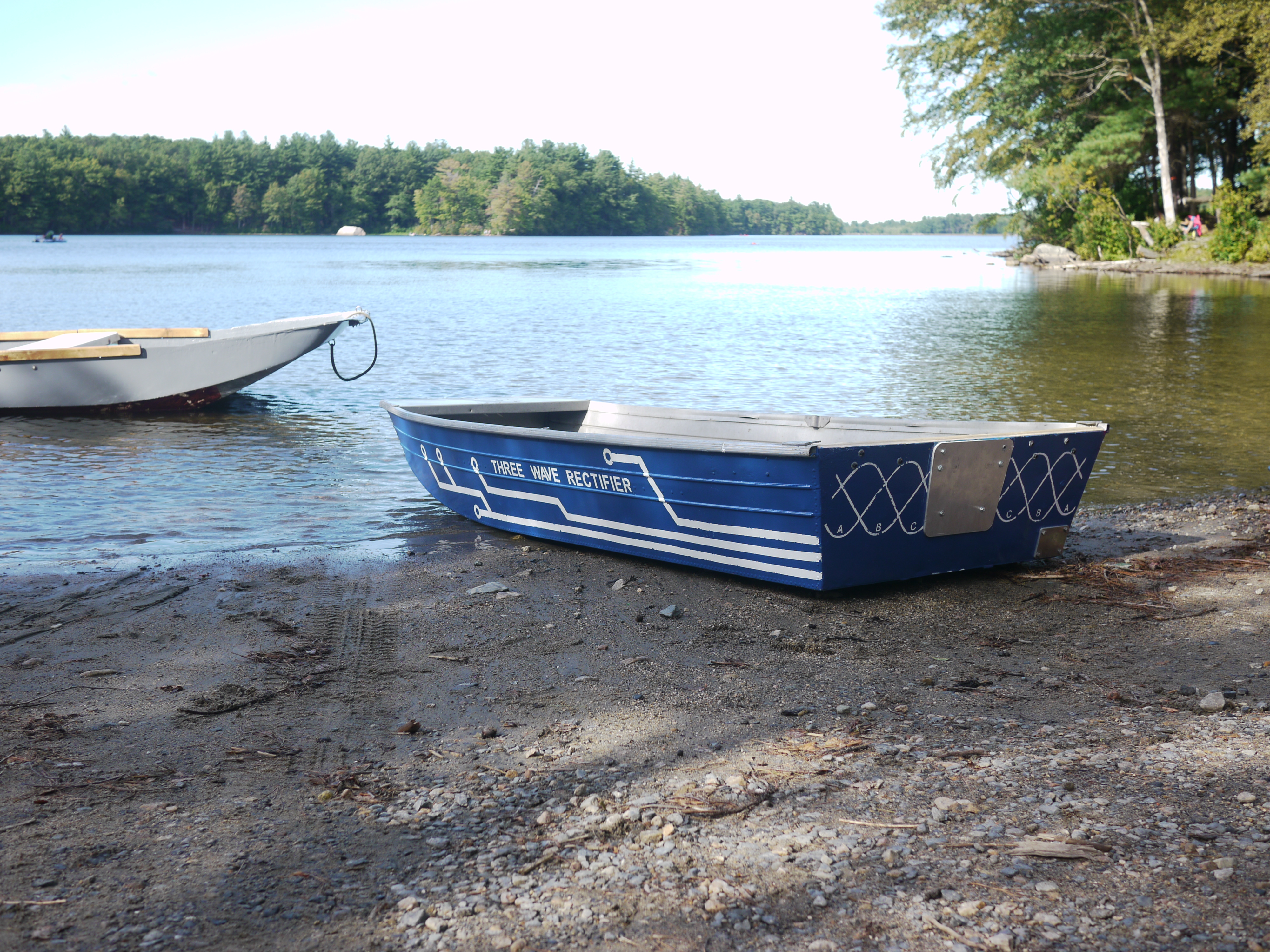 |
 |
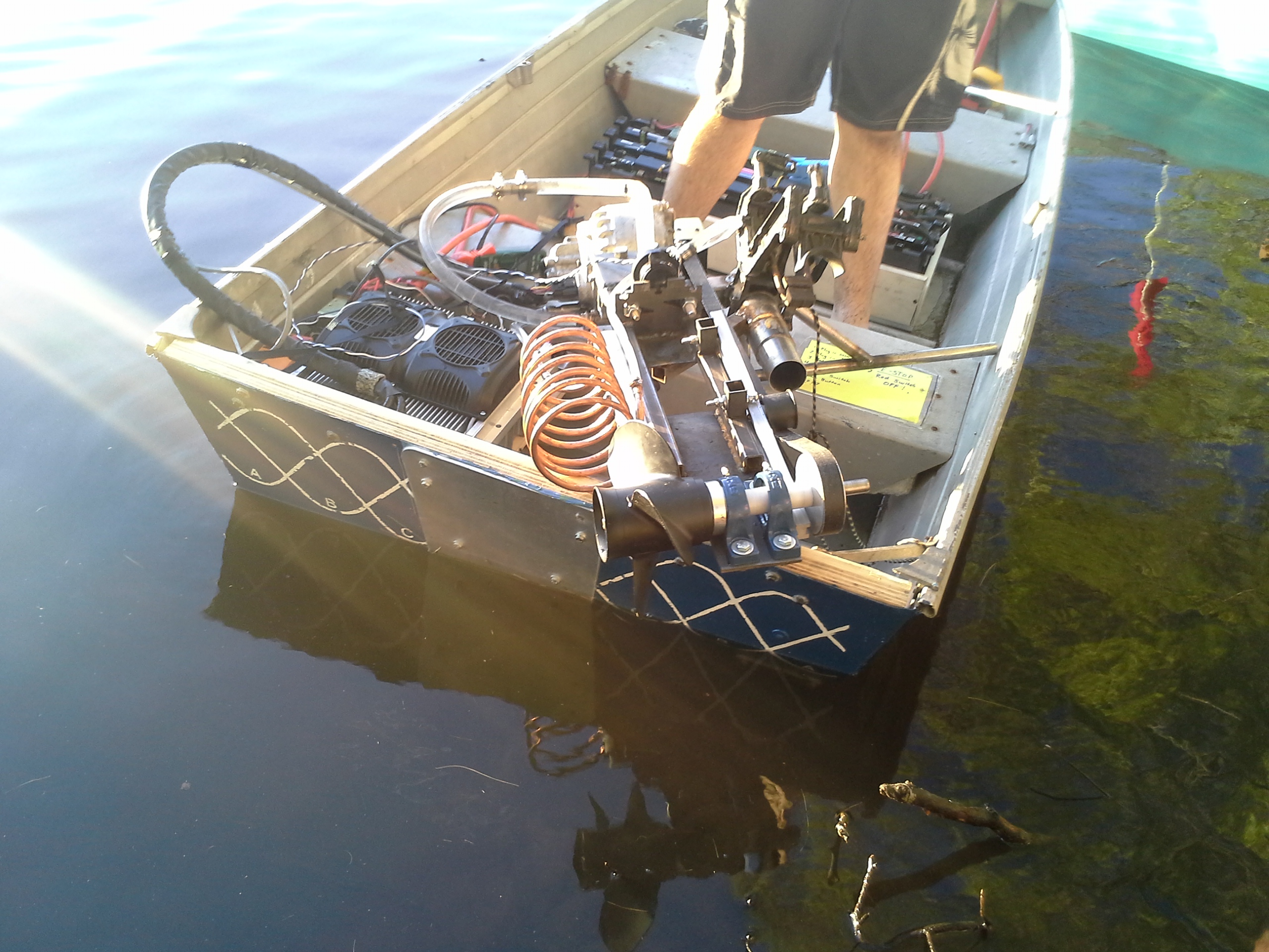
| The actual boat needed to now be retrofitted with all the electric and drive components. Notably are the outboard sub-assembly, the chilled water loop, the motor controller, battery pack and interface hardware. | 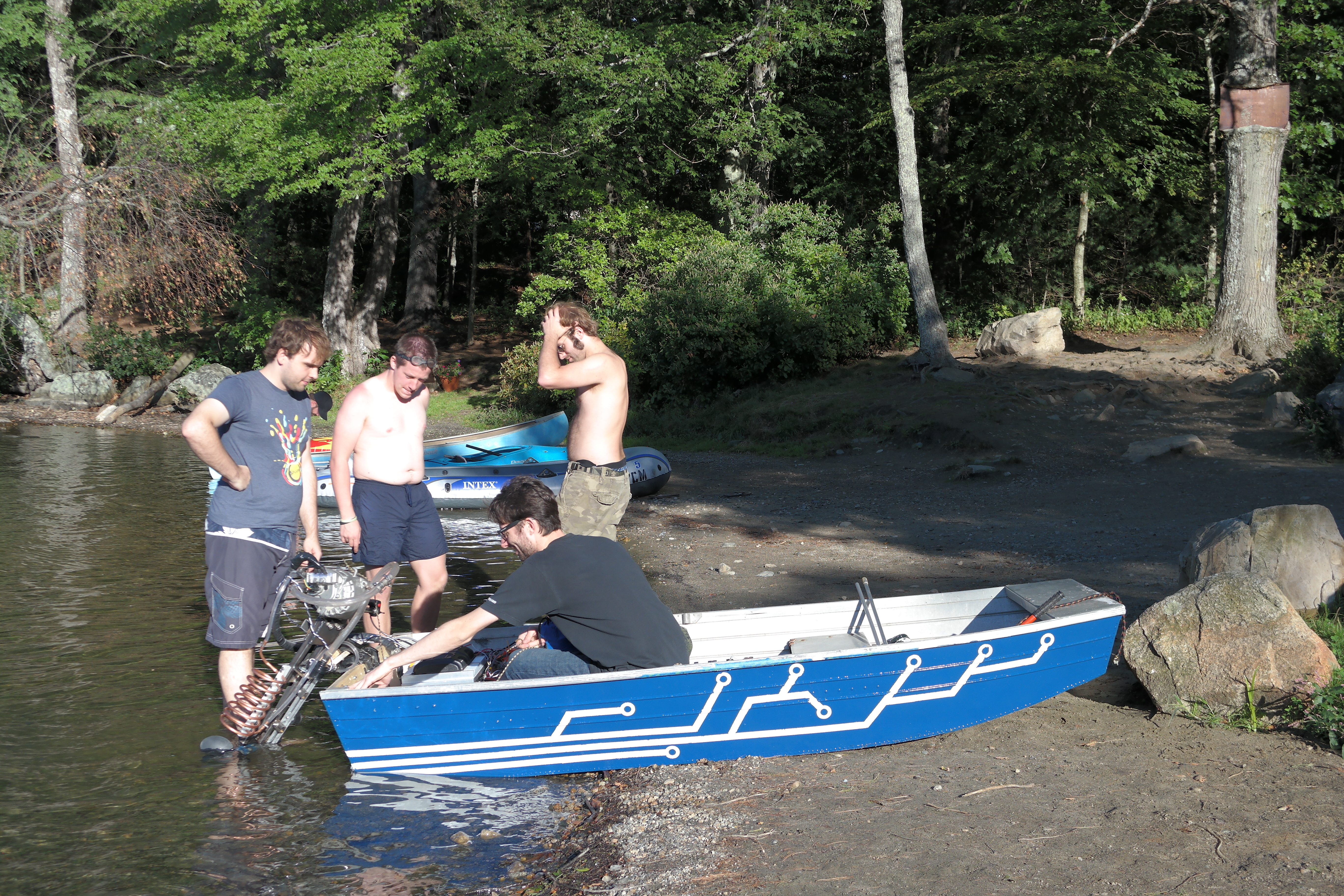 |
|
| The whole assembly was a bit precarious, the battery pack took up most of the mid-bay area while the motor controller and lever arm for the outboard took up the back portion. With 2 crew members it was a bit tight and ran fairly close to the waterline. | 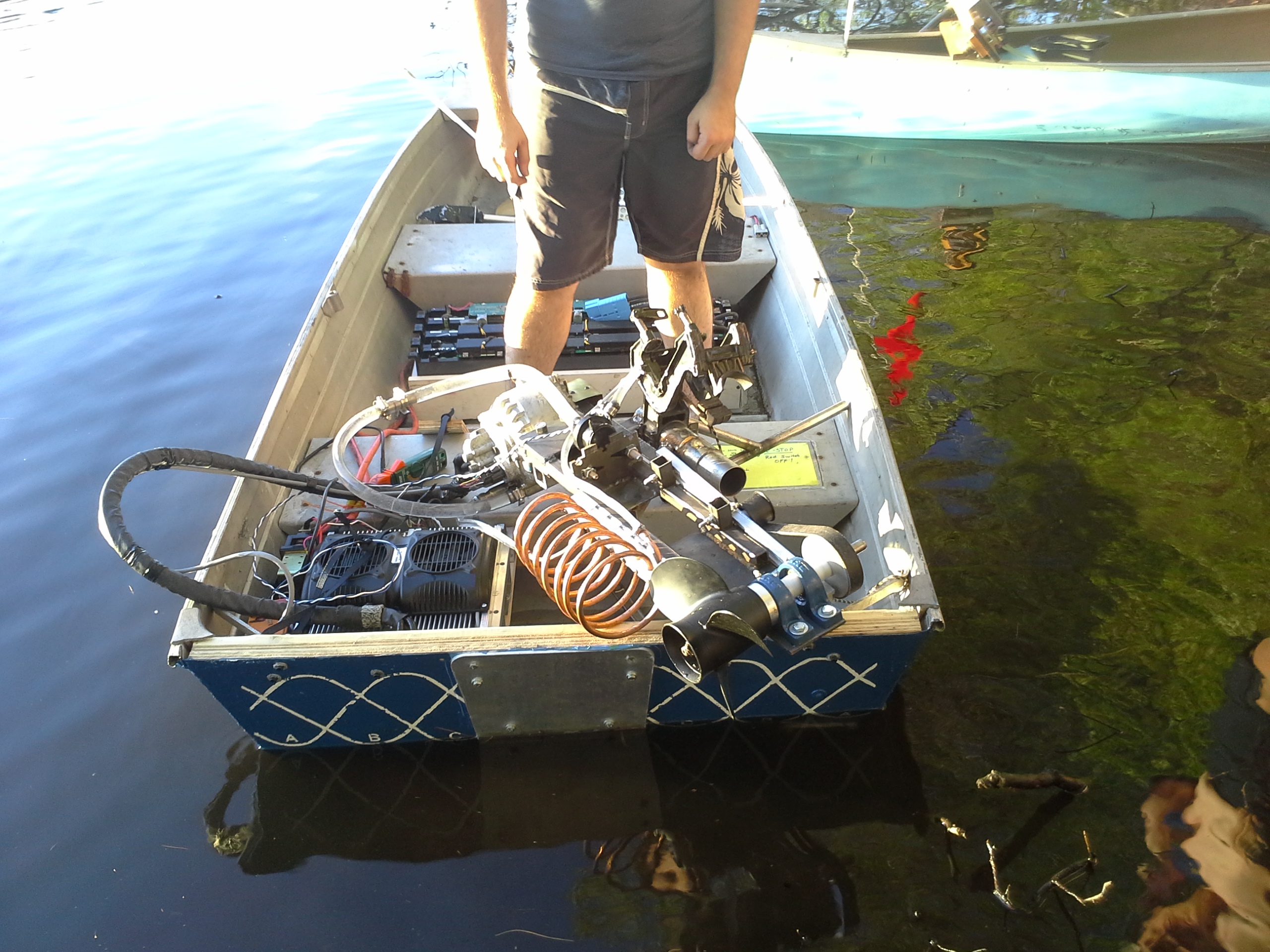 |
 |
| Success |
||
(There's
other photos in the photo gallery)
Concluding Remarks:- Simple is sometimes dramatically undervalued, this thruster has been used so far on a number of outdoor adventures, and propelled myself and comrades a total of 30 miles, the lack of a motor controller results in some curious startup transients, but otherwise works well, a shear pin located in the propeller housing prevents a stuck prop from destroying the remaining mechanicals. So far this has worked incredibly well and been a great 'plug in a 12S pack and go' assembly. Yes a brush-less / three phase / submerged setup would be quieter or sexier but there is something to be said for simple and functional.
| Donate
to Increased Science Frustrated? Want to see a 60HP (peak) electric powered 8ft boat conquer the water (and possibly skies?) Donate to the build of the Mark II, not sure what it will be called but it will be curious. Donations go directly to purchase of a new craft, electronics and replacing all the lost science. If you want to donate boat parts (like a big prop or a geartrain from an outboard) feel free to email. Otherwise Paypal donate link below |
| From the sponsors: |
|
|
If you have questions or comments, ask below or send over an email.
| Comments: |
|
HTML Comment Box
is loading comments...
|
(be
careful, im not responsible for incredibly warm DC power cabling )
Dane.Kouttron
Rensselaer Polytechnic Institute
Electrical & Electrical Power
631.978.1650
