Dane.Kouttron
[11.22.11] Theta0 V1: ServoMotor→Stepper Emulator [36v50A]
| What? Open Hardware DC Servo Motor controller talored for:
Sample
Files for each operating mode are available below
|
 |
 |
| This project documents the design and operation of the Theta0 and Theta0-V2 motor controller |
| What? | Background | Firmware Notes | Components |
Firmware | IMAGE DIRECTORY |
| What? | Image/ Media |
|
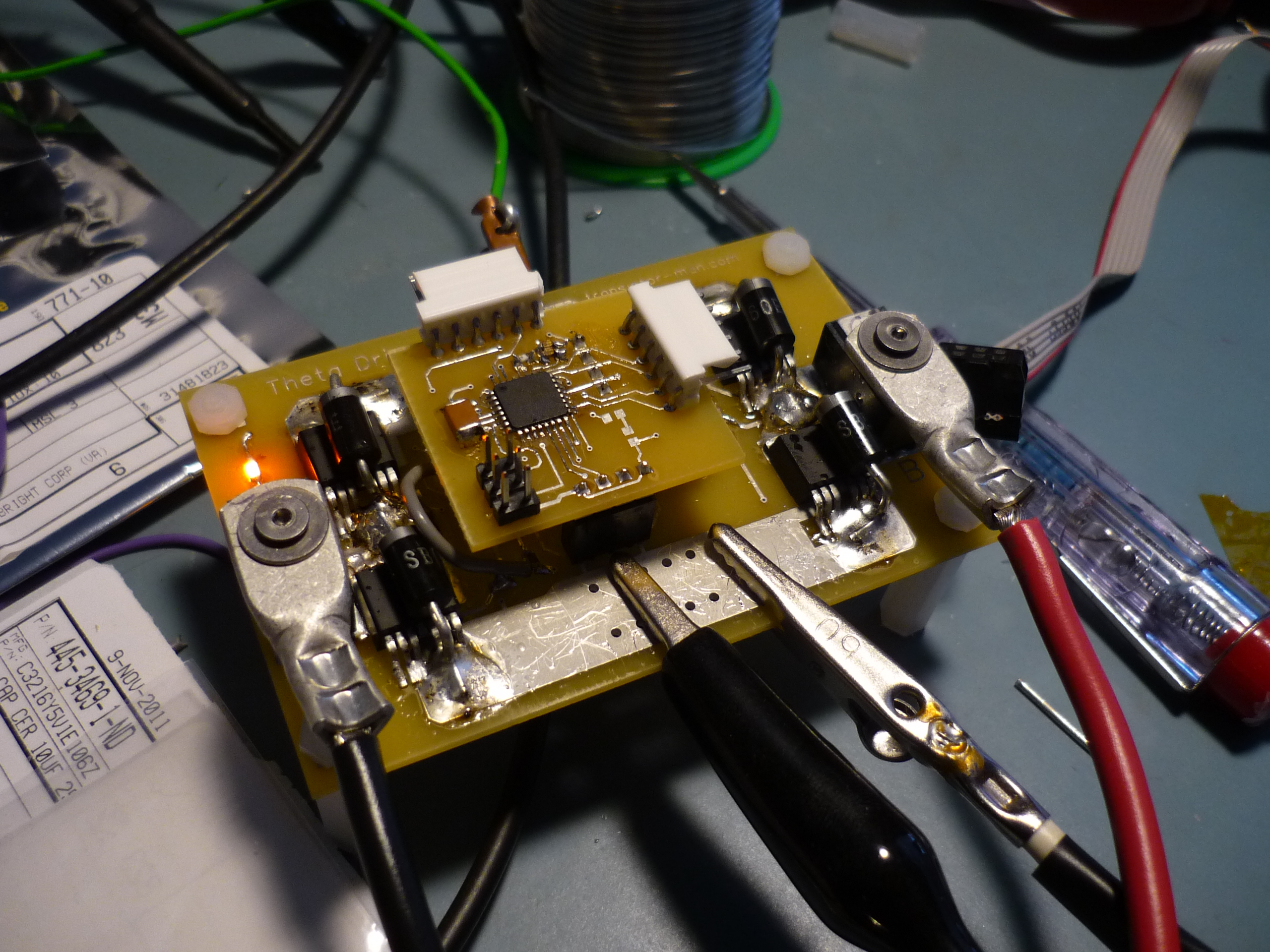
Theta0
V1 was a quick proof of concept high current dc brush motor drive. It
was sent out initially using Advanced circuits 'BAREBONES' service, which provides
a quick turn, low cost board, without the bells and whistles of a standard turn. 'Theta 0' literally derived its name from its intended purpose, controlling an axis on a robot arm, namely the theta 0 axis. |

|
| Background: | Image/ Media |
| System Architecture : The all n-channel H-Bridge topology has benefits and drawbacks. Historically and currently (2011) n-channel power mosfets have significantly lower RDS-on (operating impedance) than their p-channel siblings. Lower RDS-on equates to lower I²R losses during operation, which is a significant benefit, especially for non-actively cooled designs. The drawback to a completely n-channel design is driving the high-side mosfet. The voltage necessary (between gate and source) to turn on the gate for a power mosfet is generally 10V, with an absolute maximum at 20v. As the source of the high-side mosfet can float up with the device it is driving, switching 10v greater than the supply can be difficult. One option would be to provide isolated power, however an isolated power supply, can become pricey, and eat up board real estate. A 'flying cap' or 'bootstrap capacitor' is a topology that takes advantage of motor controllers discontinuous operation to provide a high side temporary power supply in the form of a switched capacitor. |
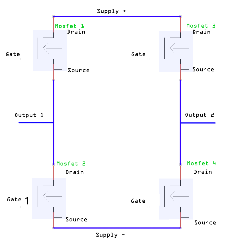 |
| That doesnt look difficult to drive, tell me more... The operating mode of the H-bridge is really simple, for each leg, you either turn on the high side OR the low side mosfet and the output either locks high or low. For a DC motor, connected between the outputs of 2 legs of an H-bridge, you can swing 1 legs output high and the other leg low, causing a positive voltage potential across the motor. By reversing the drive for each leg, you reverse the voltage potential across the motor, reversing the motor. Powering down a motor between the two outputs only requires setting each leg to the same output state, resulting in no voltage potential differentially across the outputs. In the image (right), mosfet 1 and mosfet 4 are driven on, while mosfet 2 and mosfet 3 remain off (not conducting). The output output 1 is tied to mosfet 1's source. To turn on mosfet 1's gate, a voltage of ~10V must be applied across the gate-source (with the gate being 10v higher than the source). With an isolated supply for each high side mosfet drive, you could provide the higher voltage, but as the source outputs will swing from supply (-) to supply (+) you would need a seperate isolated supply for each 'leg'. | 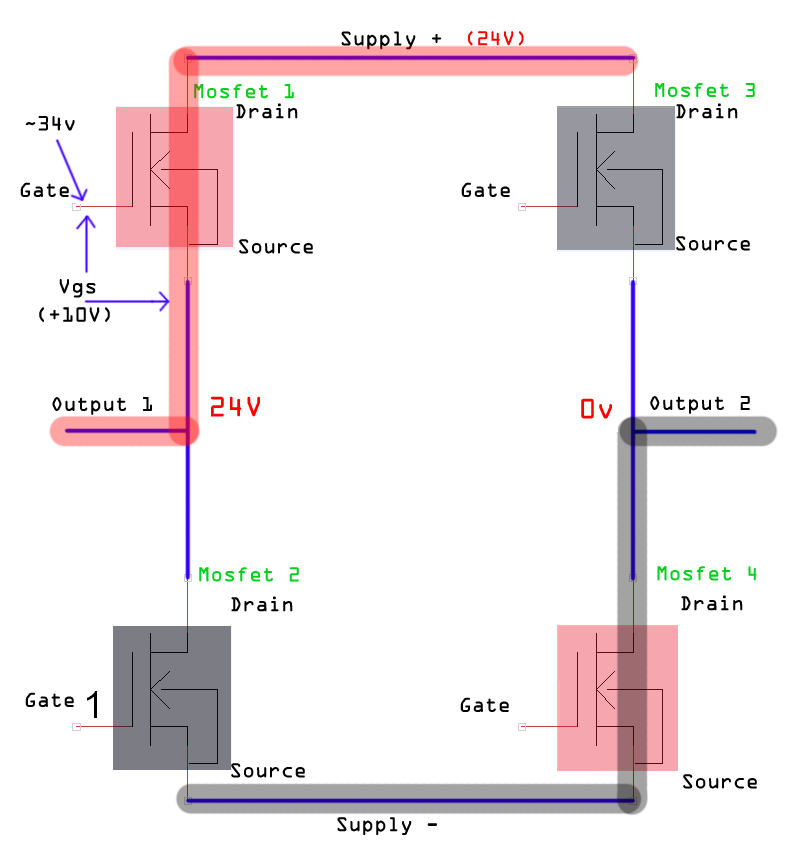 |
| Switched
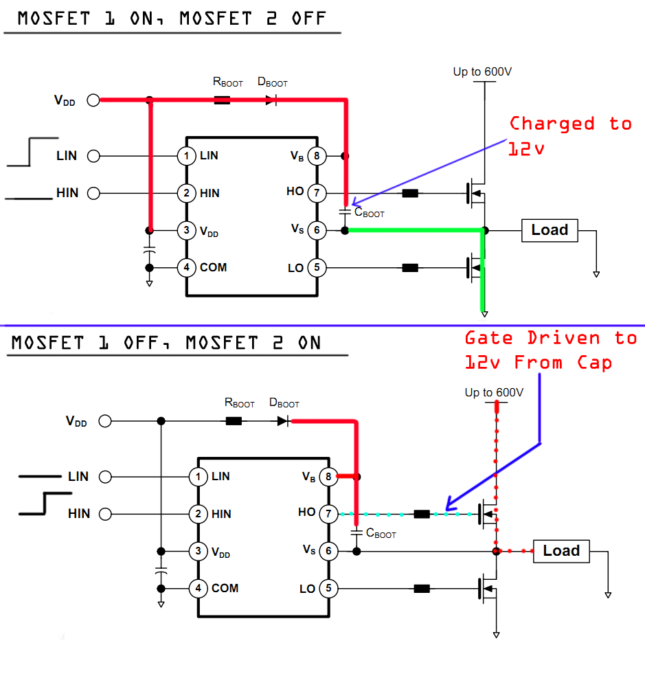
capacitor you say? Bootstrap capacitor topologies also have advantages and disadvantages. Not having to spend real-estate and part cost for a seperate isolated supply for each 'phase' of a controller is a SIGNIFICANT advantage for lower-cost designs. Shown (right) a switched capacitor can preform the tasks of an isolated supply for a fraction of the cost. In state 1 the low side fet is turned on, creating a 12v drop across the C boot capacitor, charging it. When transitioning to the high side mosfet, the C boot stored energy lives between VB and VS. An internal level shifter uses this temporary supply voltage to drive the high-side mosfet gate. The C boot value is significantly higher than the gate capactance to allow for a high voltage to remain on the driven gate. The drawback is steady state operation, a switched capacitor design can only keep up its high side mosfets as long as C boot is fullb, at best the operating duty cycle of the controller is ~97 %. For steady-state drive applications (turning a motor forward or reverse, no states in between), there are conduction losses constantly switching between states, which would constribute to ineffiencies. However, for forced feedback control systems, or sinusoidal motor drives, which are constantly switching, the system is never actually on nearly that high of a duty cycle for periods of time greater than a few hundred miliseconds. |
 |
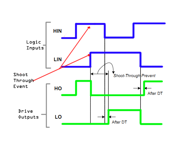
| Shoot-through and Gate Drive The IC used in this project is a Fairchild FAN 73833 half-bridge gate drive IC. It has a number of excellent operating characteristics. First, it utilizes logic and dead time based shoot-through prevention. 'Shoot through' occurs when both the high and low side mosfets are driven high at the same time. When this occurs, the system voltage feed is shorted directly to the system return. A dead time of 400ns is used, internal to the ic, to prevent this state from happening. Moreover, if the control logic outputs states that inherently cause shoot-through, the ICdefaults to both fet drives operating in the low state. Another benefit is the drives gate drive which can source 350ma and sink 650ma. These relatively high currents for fet drive are excellent for slamming through the miller-plateau and forcing the fets on or off. |
 |
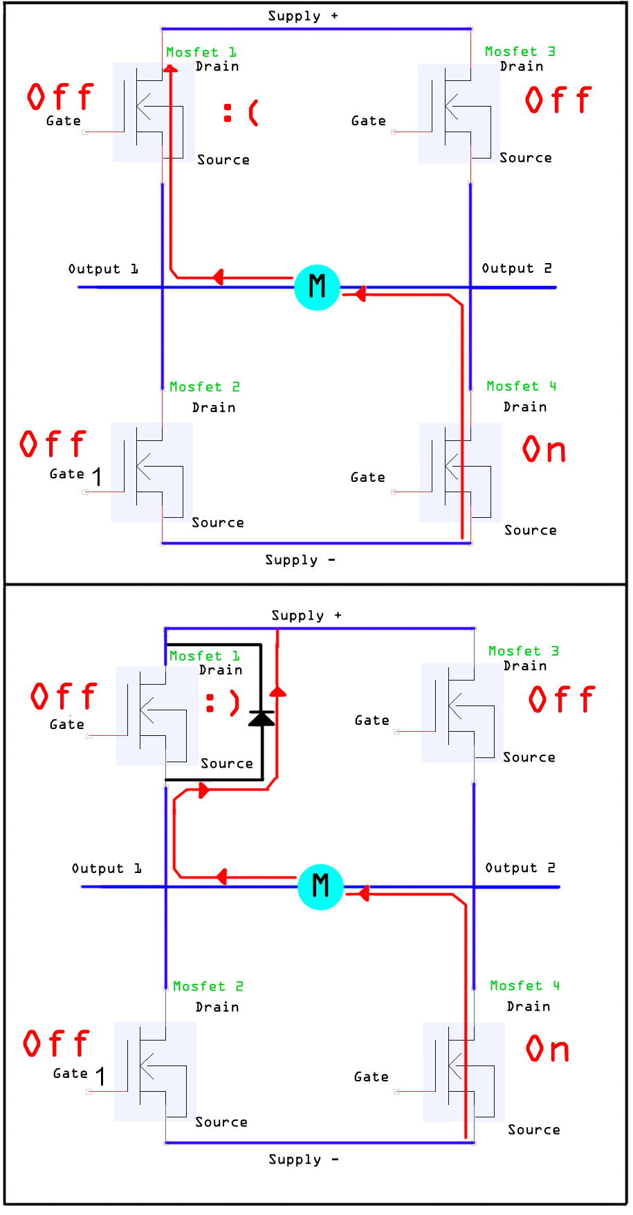
| Fast shottky diodes in parallel with power mosfets For motor control, reverse currents (energy stored in an outside load being pumped back into the controller) will flow through the internal diode of the power mosfet. Depending on the actual current through the device and this may or may not be an issue. For this design, axial shottky diodes are used, tacked in parallel living temporarally over the power mosfet. This stresses the external diode, whos rating is far greater than the mosfet's internal diode. As shown on the right, an inductive load (dc motor) is tied between output 1 and output 2. when the DC motor is operating as a generator (as it would if it this were used in a DC Brushed Scooter rolling faster than its drive capability) this current source will route current through the internal diode of mosfet 1. The internal diode on a power mosfet is only capable of temporay operation at low currents, if an excessive current is applied, it will fail, causing the mosfet to fail. An external shottky diode (A diode with an inherently low voltage drop) can be used to route anything from inductive spikes to regenerative energy from the motor. Shottky diodes are used due to their inherently lower voltage drop (.3v) than a standard diode (.7v). For power mosfets with a forward voltage drop greater than the shottky diode that is in parallel with it, the shottky diode will take all the stress during the inductive kickback. Even if the power mosfet's forward voltage is equal to the forward drop of the external shottky diode, the load current across the internal diode will cause the voltage drop on the mosfet to increase, due to inherent characteristics of the diode. |
 |
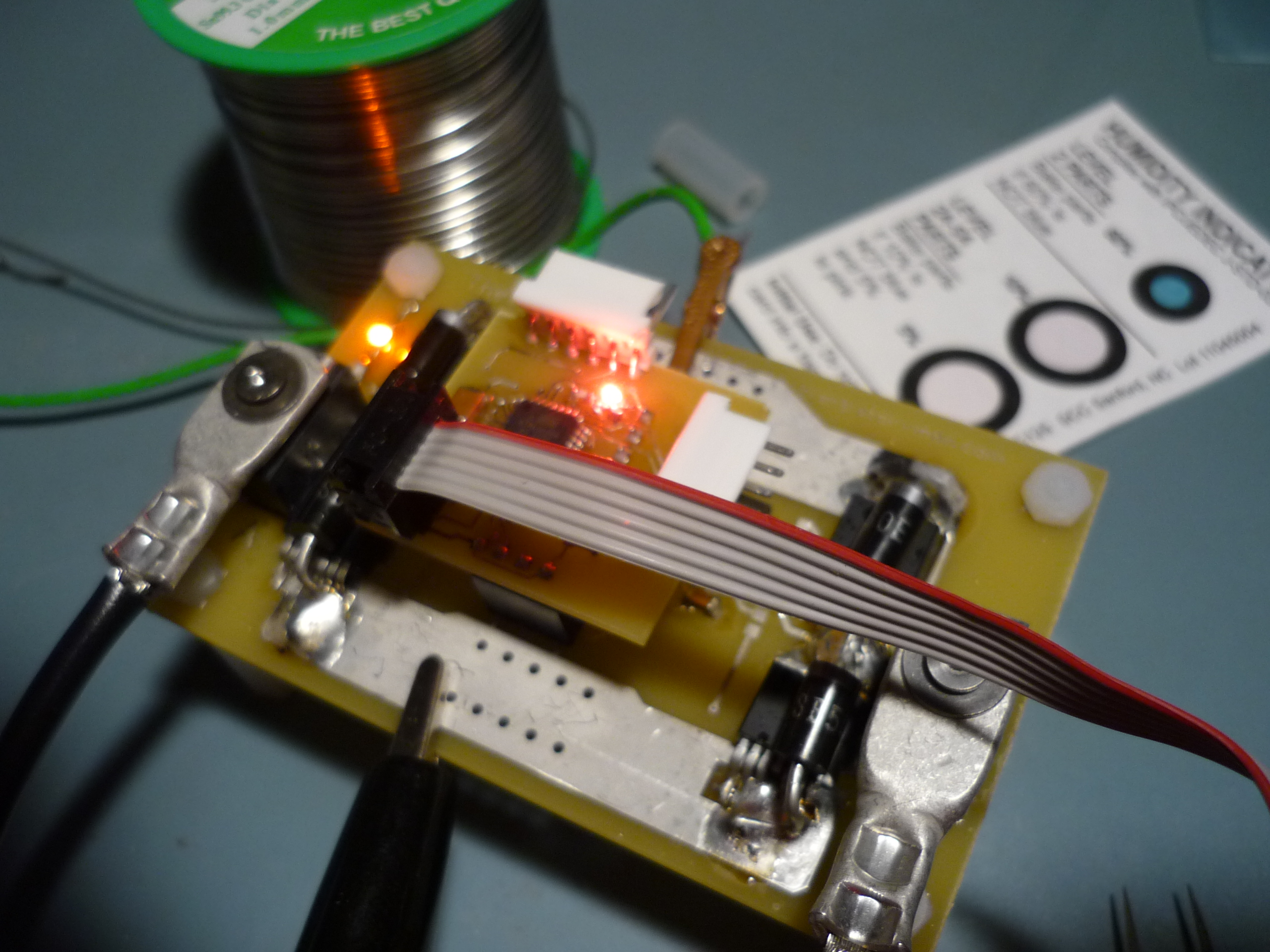
| Microcontroller living above the power electronics This arose from 2 design decisions: [1] Replacing a blown micro without having to hot-air-stencil it out is extremely useful and excellent for debug [2] The microcontroller board does require significant real-estate. Total height was of less concern than length For higher current designs, where the power electronics pcb is 2+ ounce copper, it may be difficult to have the same tiny tssop sized pads successfully etched. As a seperate connectable card, the power electronics could be upgraded to 2+ ounce copper while the microcontroller board could stay 1 ounce or below. |
 |
FIRMWARE
| DC Brush Motor Stepper Emulation [Firmware] | |
|
Operating Loop |
|
| Details and feedback |
| Sinusoidal AC Comutation [Firmware] | |
|
Time Lag before executing One THING ABOUT WILDLY. |
|
| Microcontroller PWM Frequency hshs | |
| Sample DataSets | Graph | DataSet |
| Controller 10 Khz Commutation, 1A load (resistive) | 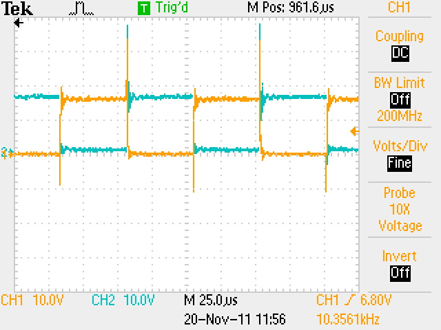 |
|
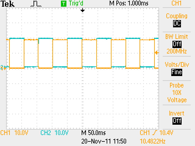
| Controller
at 10hZ comutation, 1A load (resistive) |
 |
|
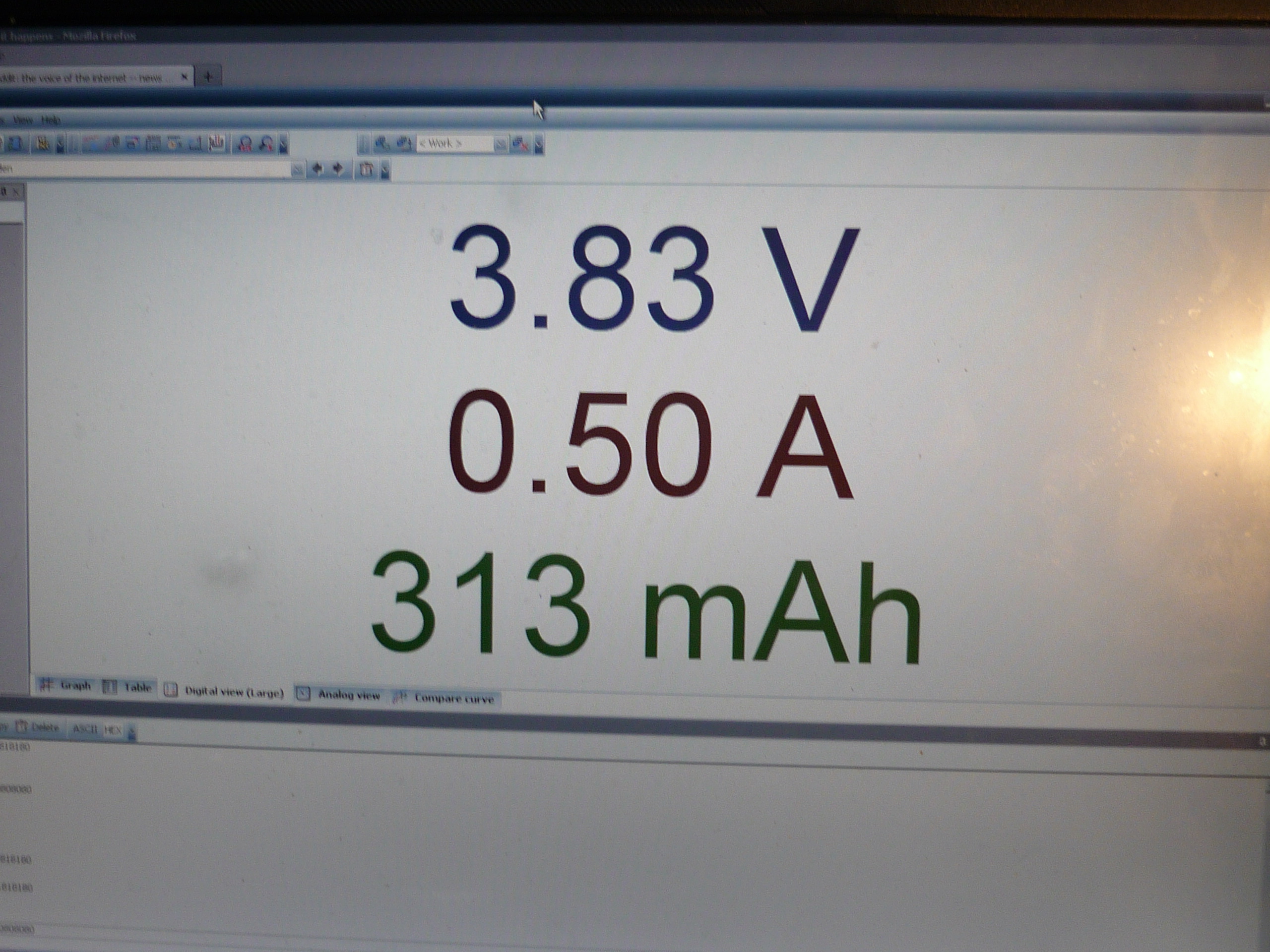
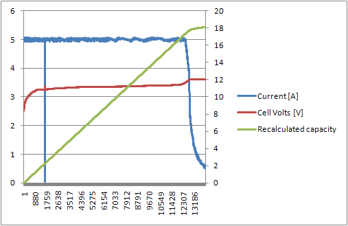
| Single
Scooter Pack block, 9P 26650 5A charge plot
|
||
This project complies with the OSHW 1.0 definition
(There's
other photos in the photo gallery)
Concluding
Remarks:
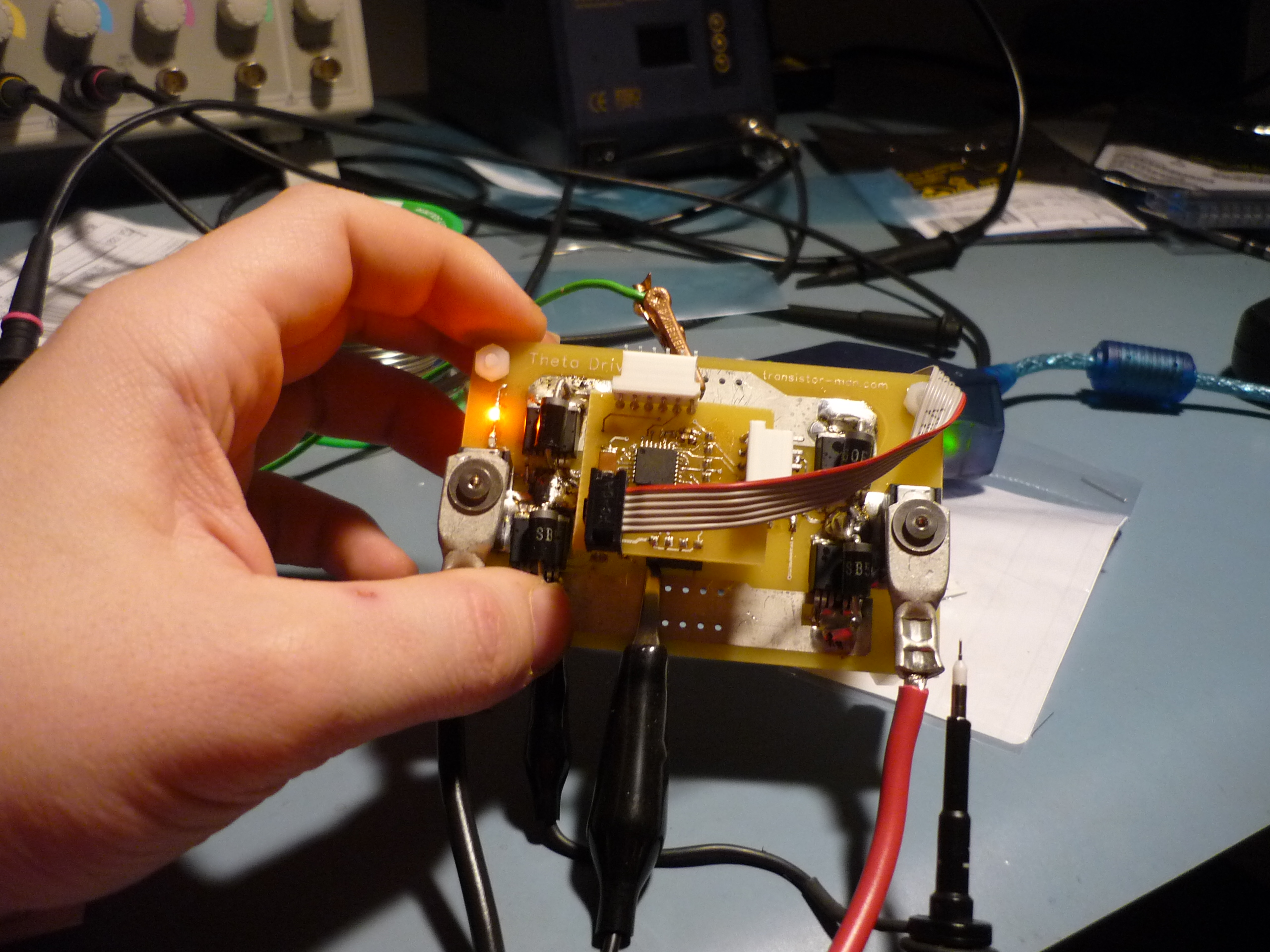
As my first 'flying cap' bootstrap motor control attempt, this worked extrodinairally well, after some minor modifications. A jumper was installed between the 5v ground and power supply ground, the resistor value for Rboot was changed from 2 ohms to 0 ohms,.
if you have questions or comments, shoot over an email.
References:
| From the sponsors: |
| Comments: |
|
HTML Comment Box
is loading comments...
|
(be
careful, im not responsible for your exploded battery pack)
Dane.Kouttron
Rensselaer Polytechnic Institute
Electrical & Electrical Power
631.978.1650
