Dane.Kouttron
[12.15.14] Upgrades To The Flying Nimbus
| Flying
Nimbus Upgrades Ahoy! Enjoy Nimbus MK1? The following details upgrades to the Nimbus project, to increase its load handling capability, range and night-time visibility. If you haven't checked out part 1, do-so now! (its a bit of a read) |
 |
 |
| What? |
Battery Upgrade | Rear Lights | Wheel Upgrade | Motor Swap | Grease & Weld | CAD Files | Conclusion | Image Directory |
| Battery Upgrade | ||
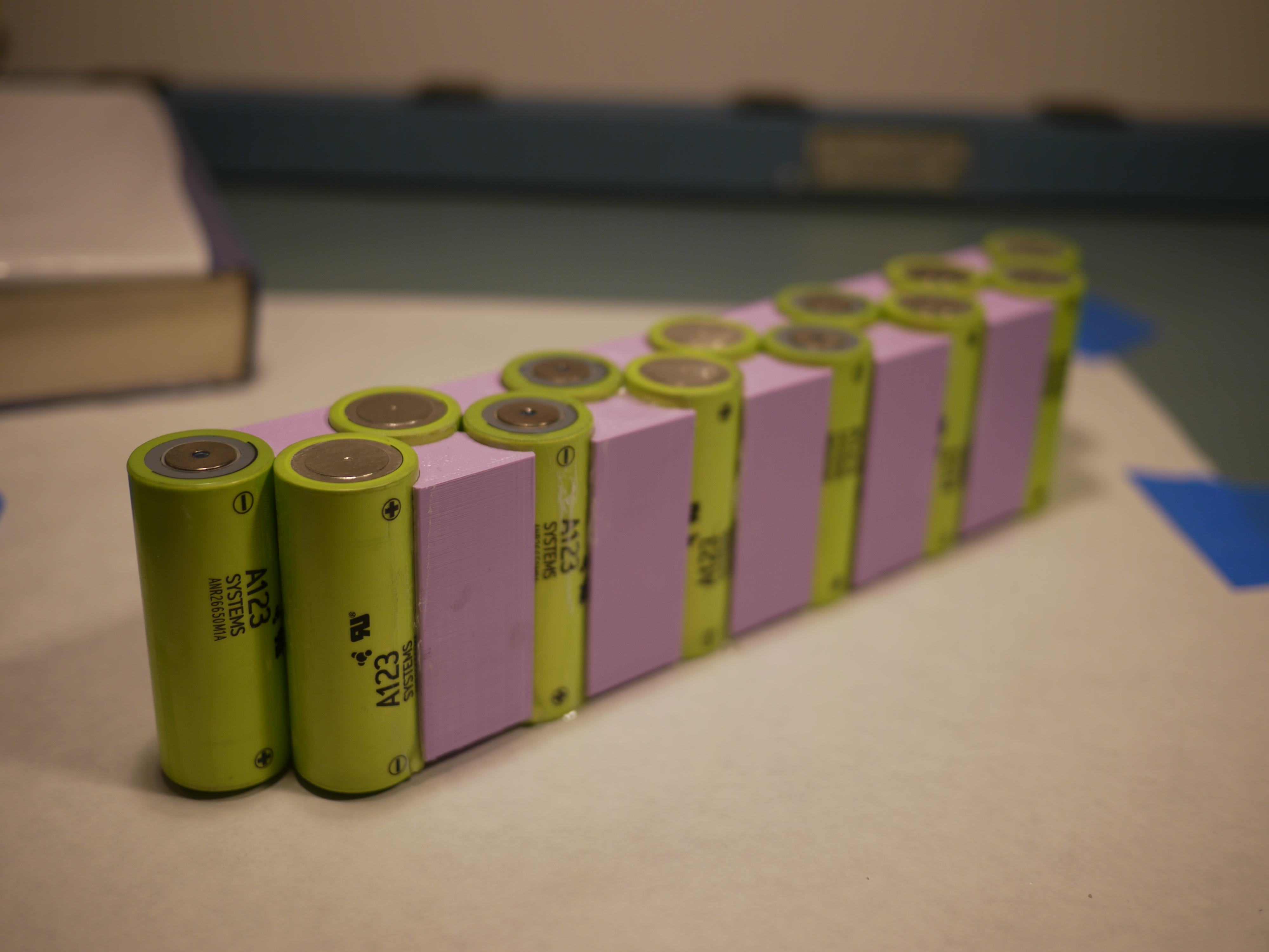
| The battery pack has an odd volumetric constraint, the 26650 cells will not stack vertically, and horizontal packing does not achieve the necessary pack voltage / capacity. So a very precarious spacing was solved with precision printed cell spacers. I determined that using A123 26650 M1A cells, at 2.2-2.3AH/cell, i could squeeze in an extra 20% energy capacity in the same volume. It appeared that the stock 18650 cells didnt quite hold up as well over time and had fallen to an average of 940mah/cell. This could simply be that the cells were aged (manufactured circa 2008). Either way, more energy, more range ahoy! | 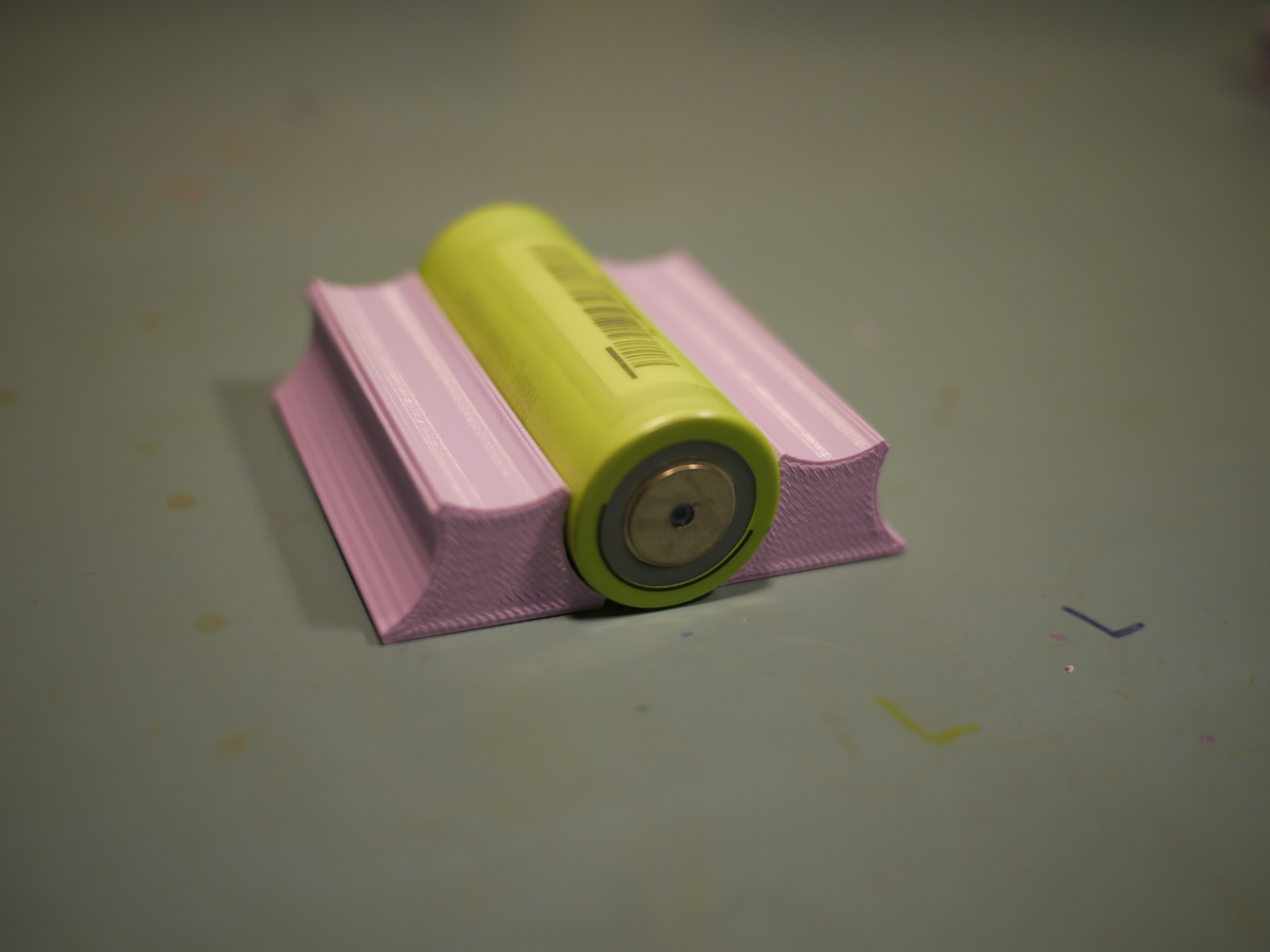 |
 |
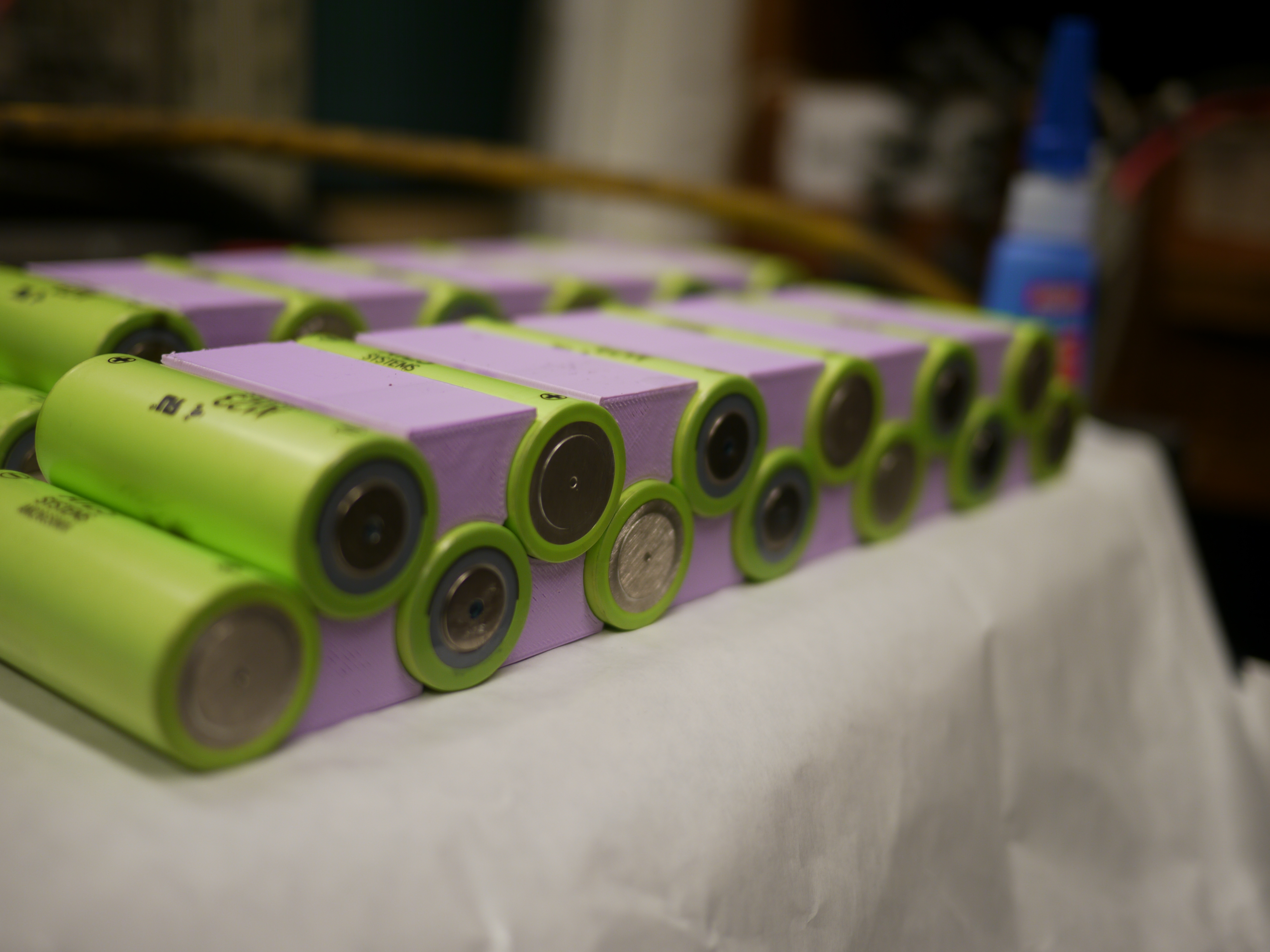
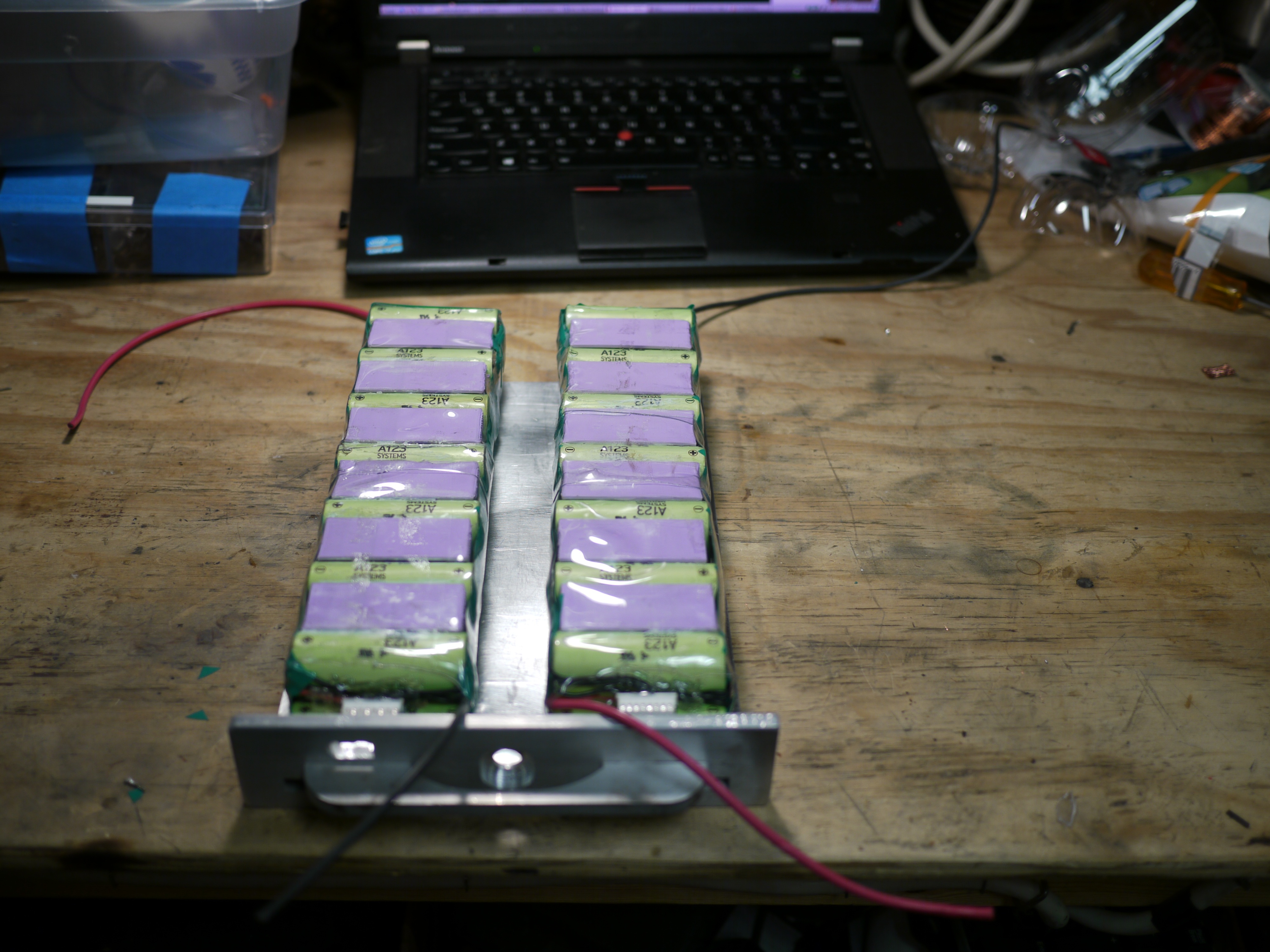
| And lo, a glued together 3d
printed battery array! To meet the volumetric requirements, i glued the cells to their respective holsters. The cell group is setup to create two 7S2P cell arrays. Its important to keep the modules 'straight' as any bowing in the setup would result in it not fitting correctly on the tray. Note the final cell holster is missing in this view. |
 |
 |
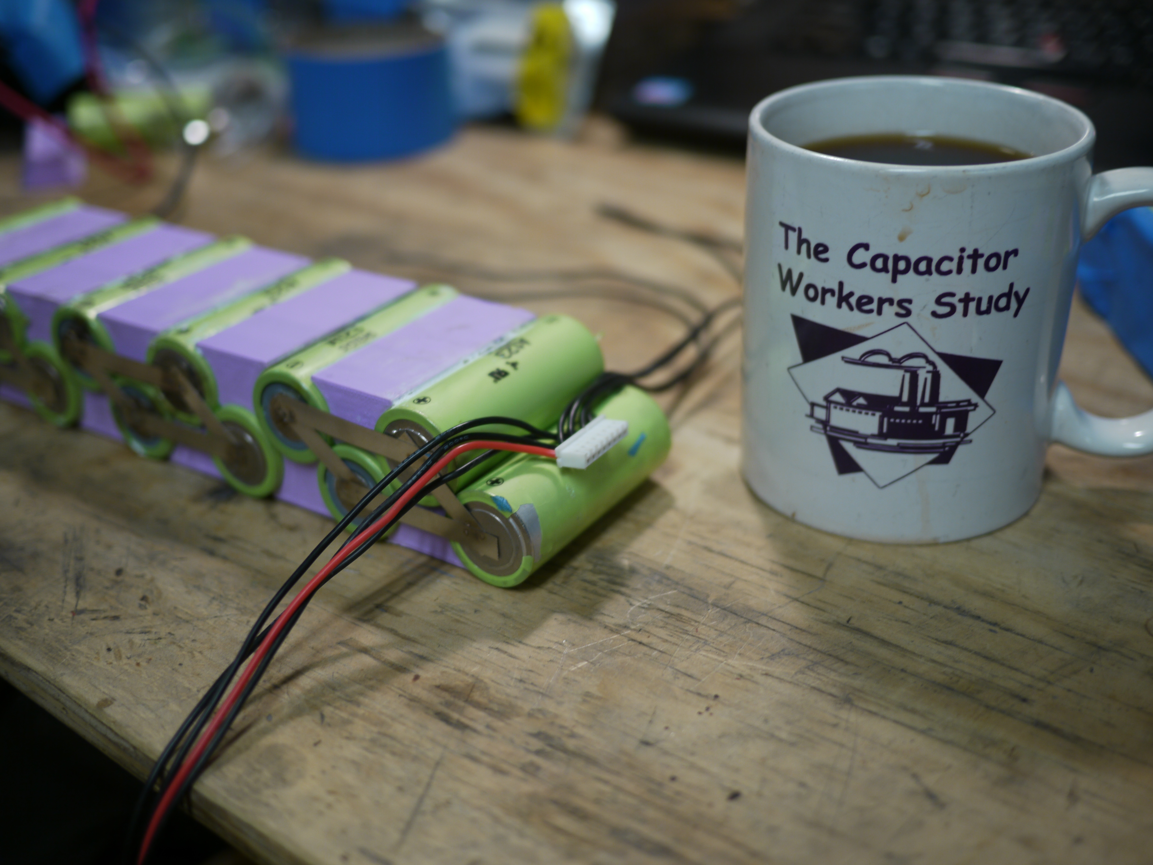
| Welding
and Adding balancer leads For the cell-cell connection, 3/8" wide nickel strip was welded to each cell using a DIY resistive welding setup. A 7S balance lead [link] was added and soldered between each group. The location of the balance connector is fairly short. An extension [link] can be used to bring this balance connector (JST, 7 position) out to an external balance charger. |
 |
 |
| Heat
shrunk 1L bottle 'armor' Four 1L seltzer bottles served their country and were cut-up to form the heat-shrunk casings for the cell arrays. Unfortunately they were actually a bit too thick, the battery array barely fit. Back to the drawing board. Shown, the hole and mounting point for the 50A dc circuit breaker and xt-60 charge port. |
 |
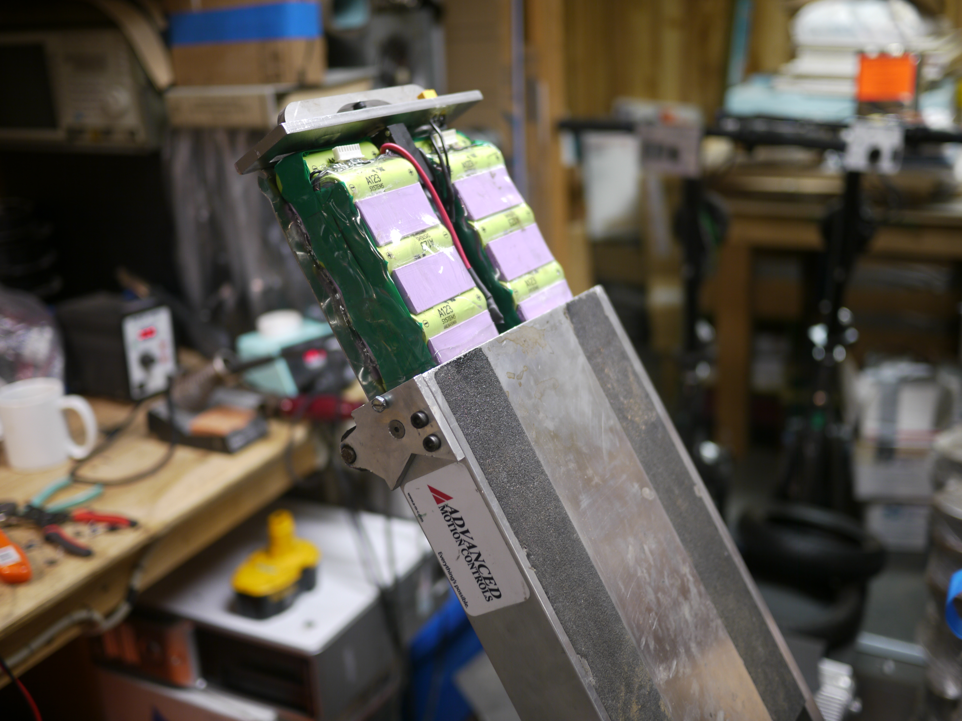 |
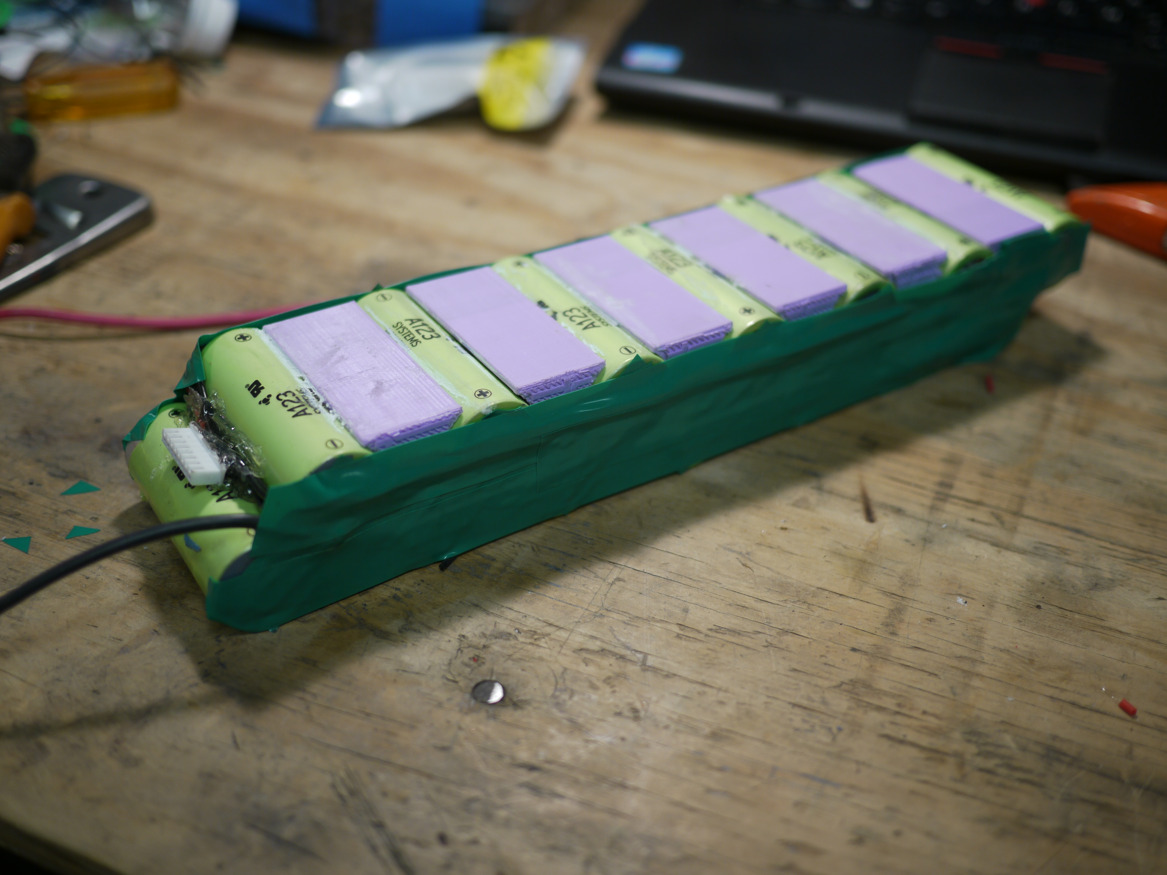
| Swankier
battery heat shrink The heat shrink used was purchased from [link] Its fantastic stuff. These battery modules were then adhered to the tray. Tape and extra packaging was used on the outside of the cell groups to aid in wear and tear. The balance connectors are also visible in the front of the module. |
 |
 |
| Machining
the battery bay end-plate to allow for slightly more space Well, it all mostly fit, but some secondary machining on the end plates was needed to capture the last cell group. |
 |
 |
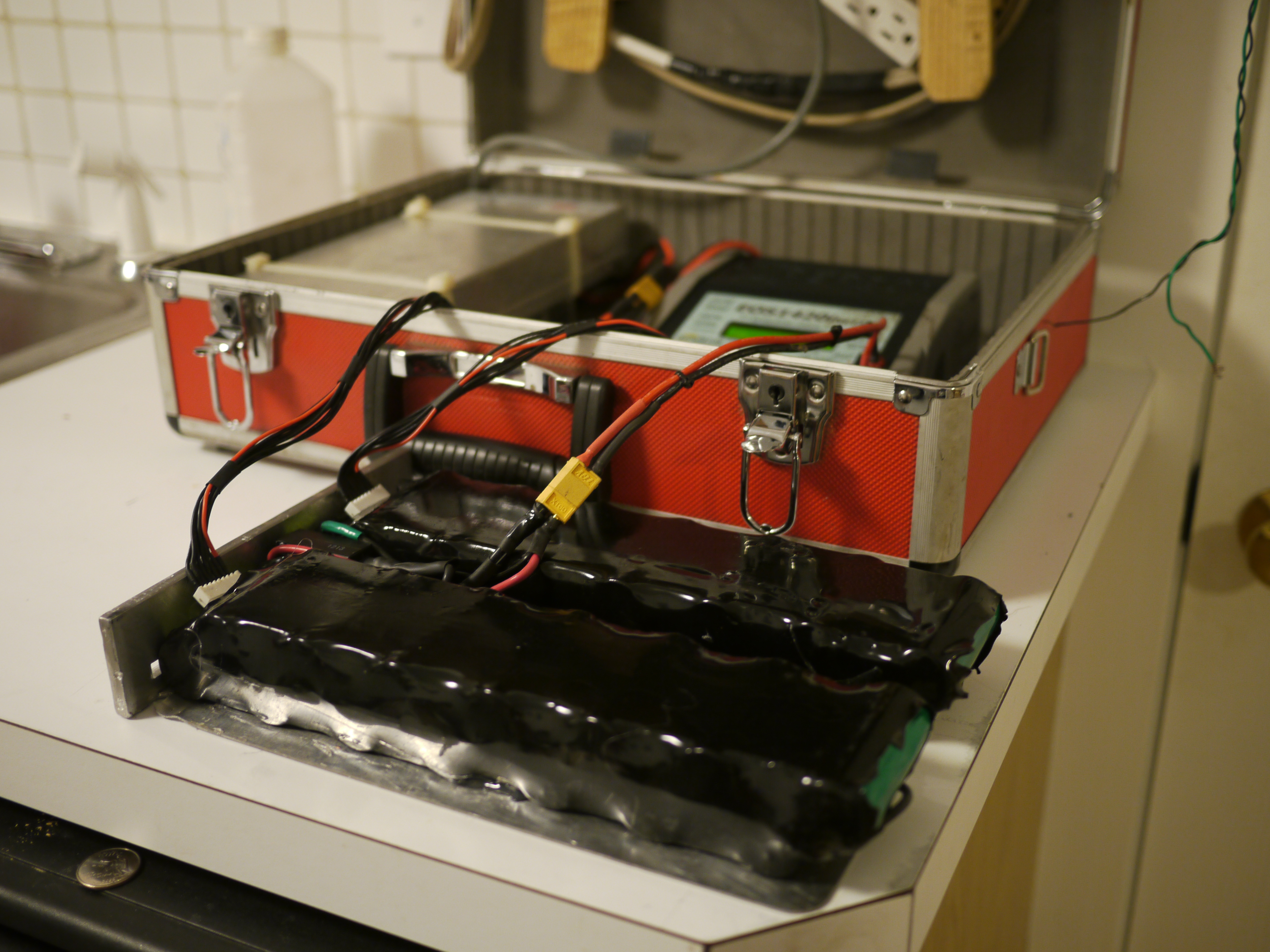
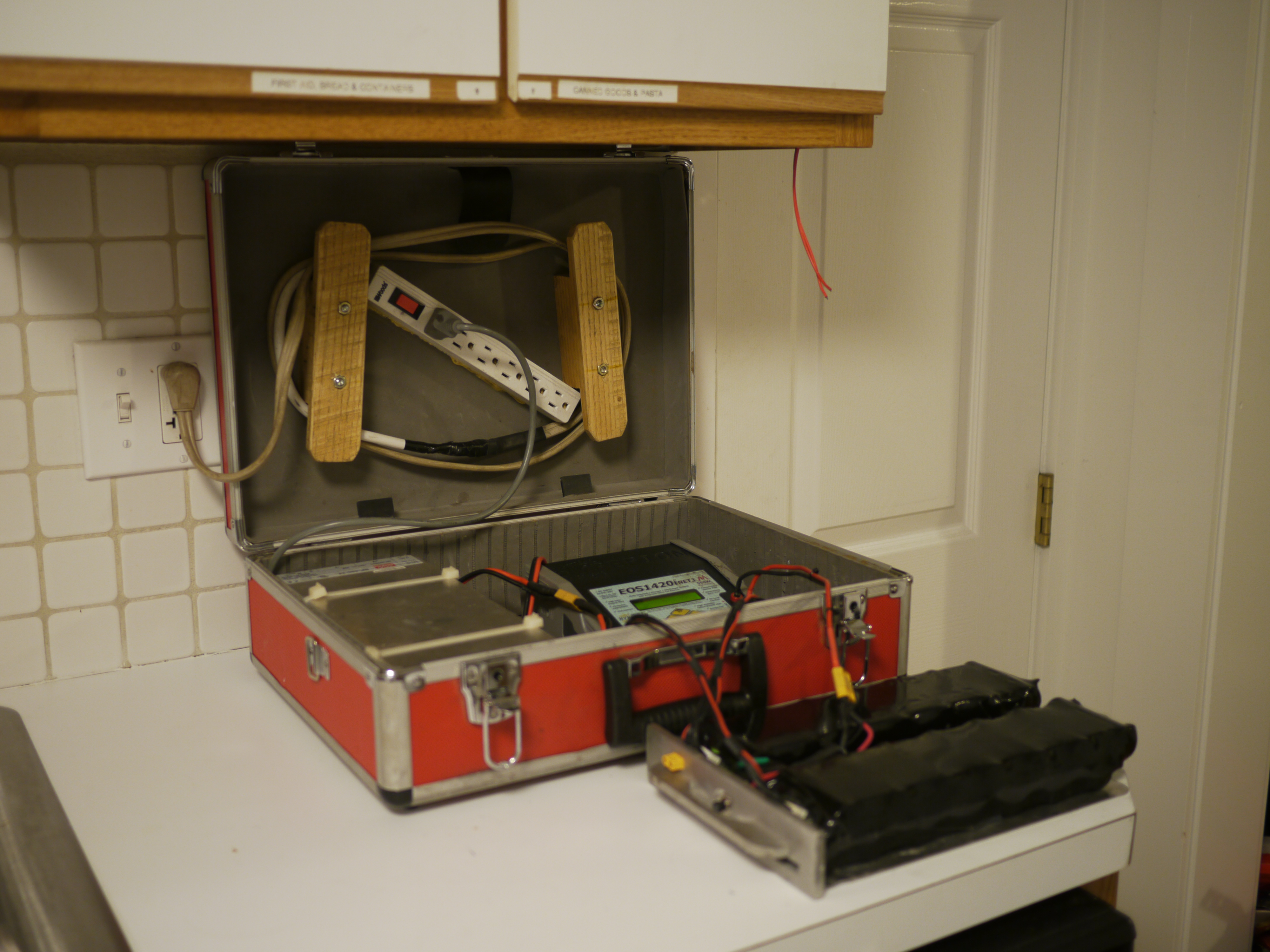
| Balance
charging For charging, a Hyperion 1420i 500W balance charger was used. Shown in its swanky DIY harbor freight suitcase. More to come on the Hyperion setup! |
 |
 |
| Upgrade
from 18650 [14S4P] to 26650 [14S2P] Here's the reason for the upgrade, a move from 3.6 Ah to 4.75Ah, surprisingly 30% increase in energy density, and a lower impedance to boot! Data collected via Hyperion 1420i <Note the plot titles need updating> |
14S4P
18650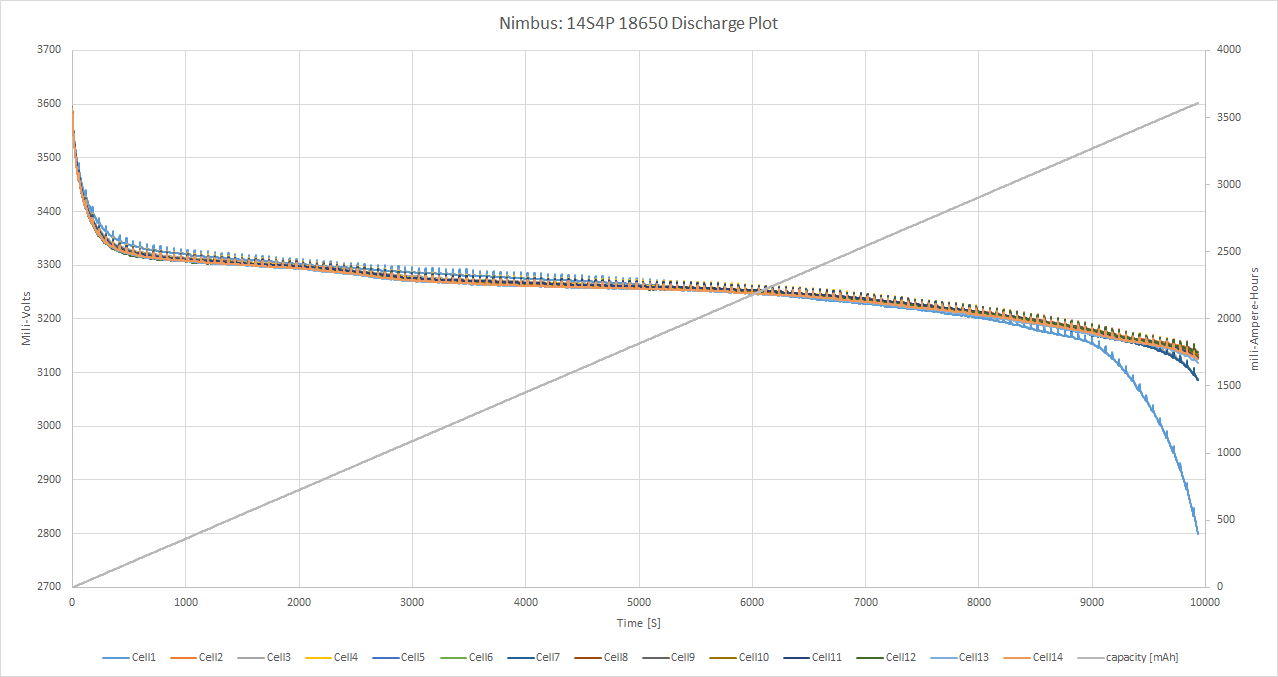 |
14S2P
26650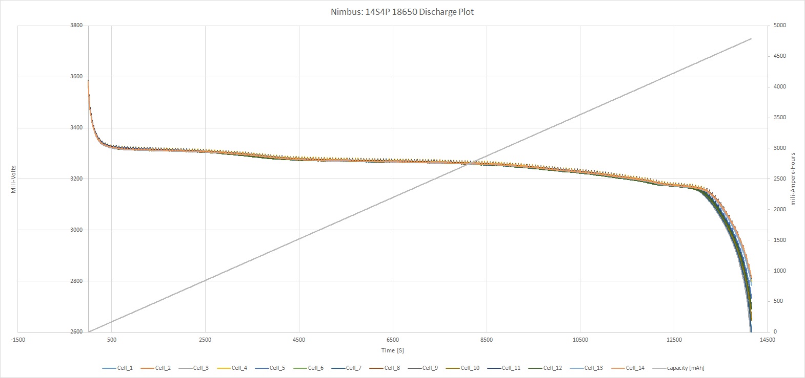 |
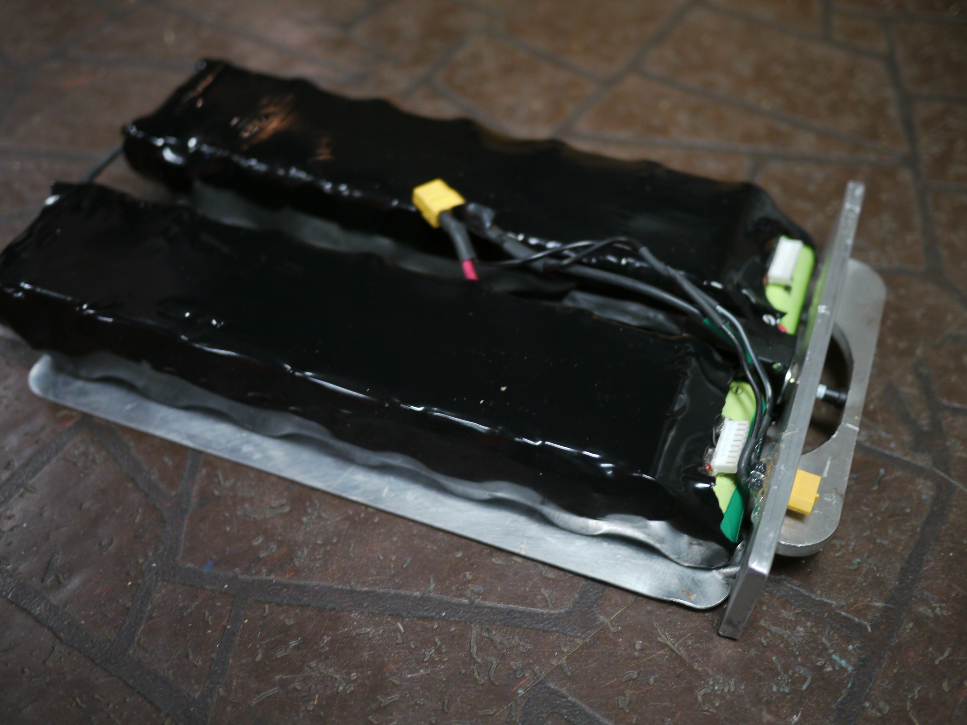
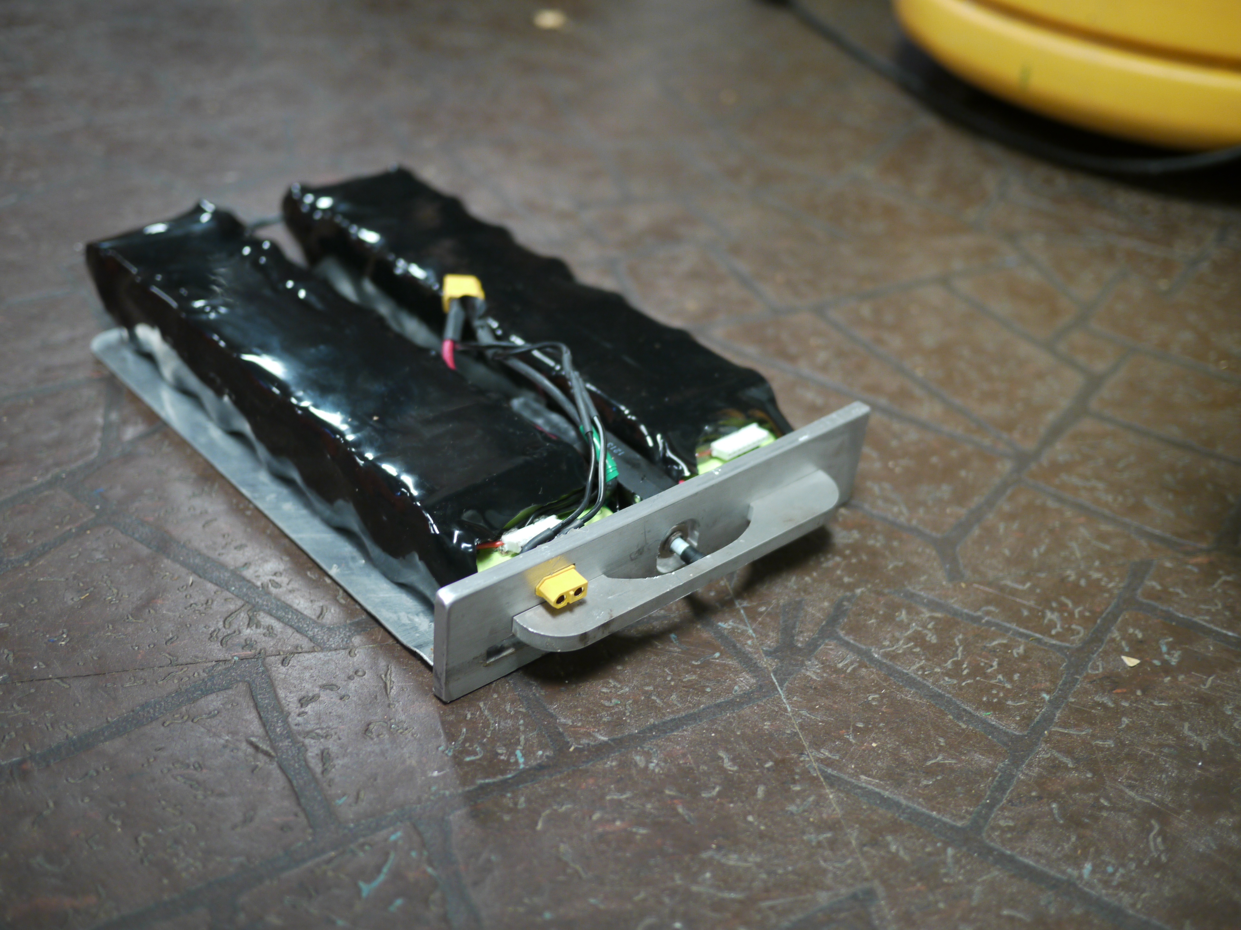
| Shown are both packs back to back. Each includes the 50A dc circuit breaker [photo], while the newer pack includes a rear XT-60 charge connector. | 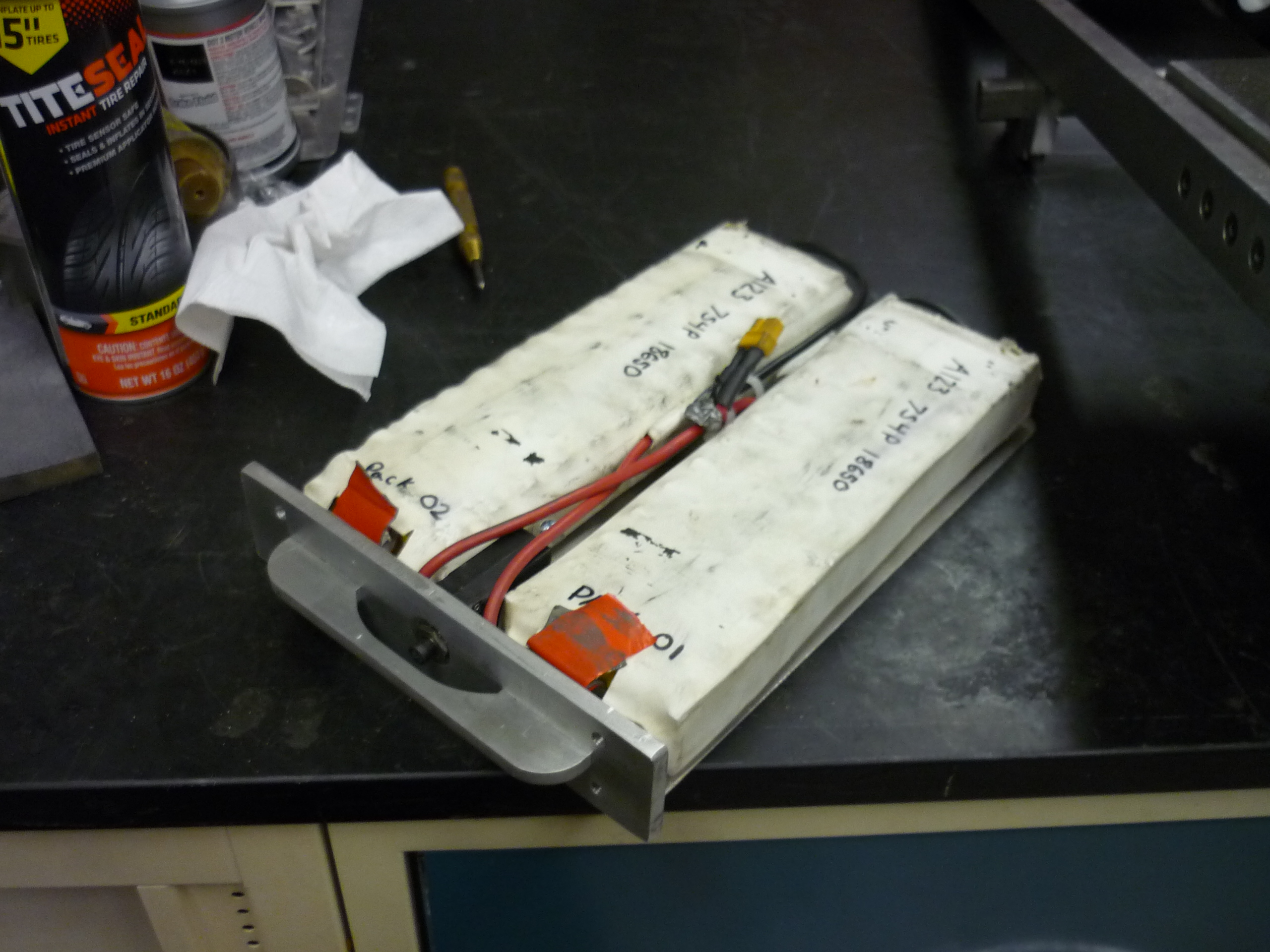 |
 |
| Rear Lights | ||
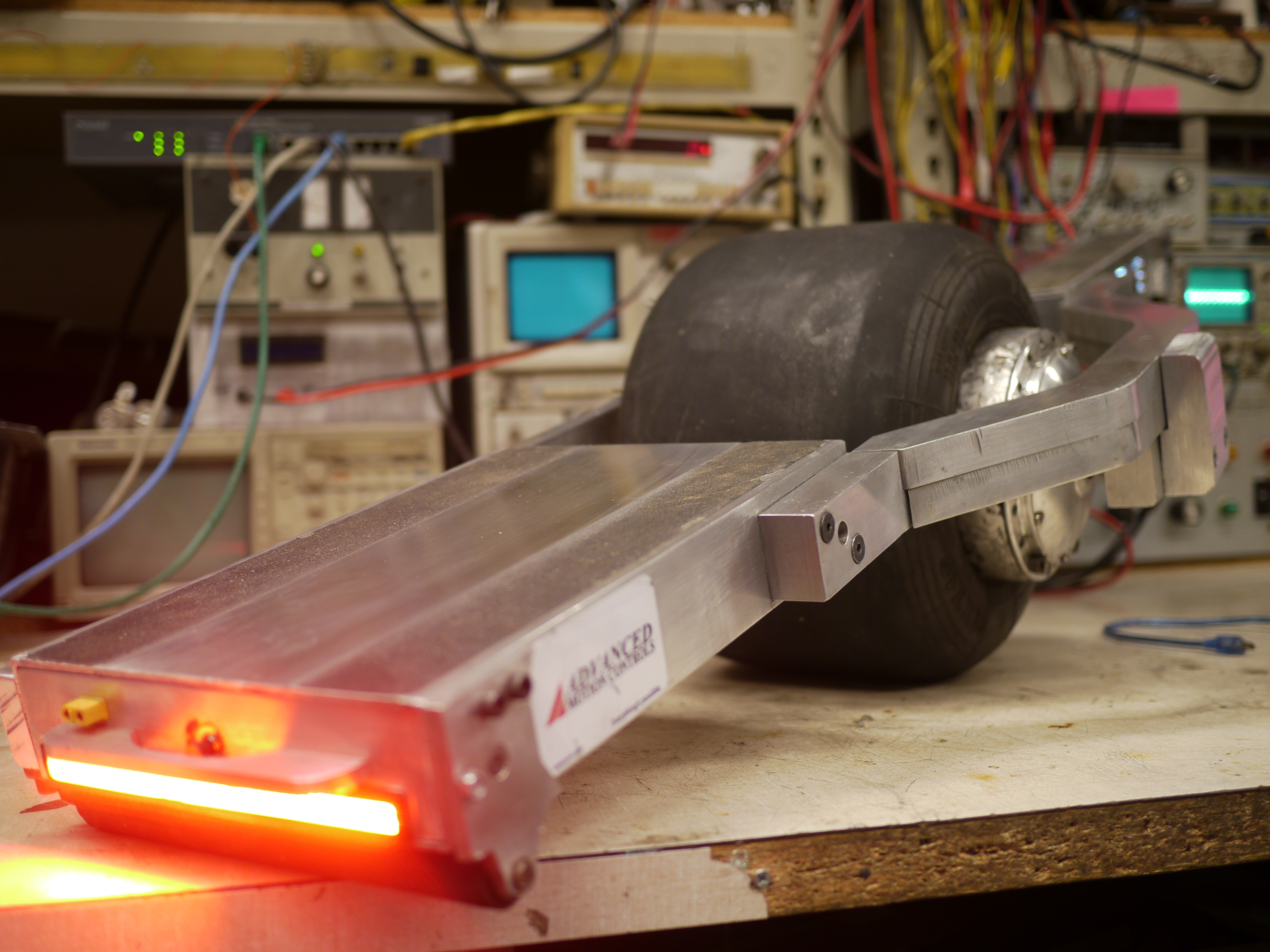
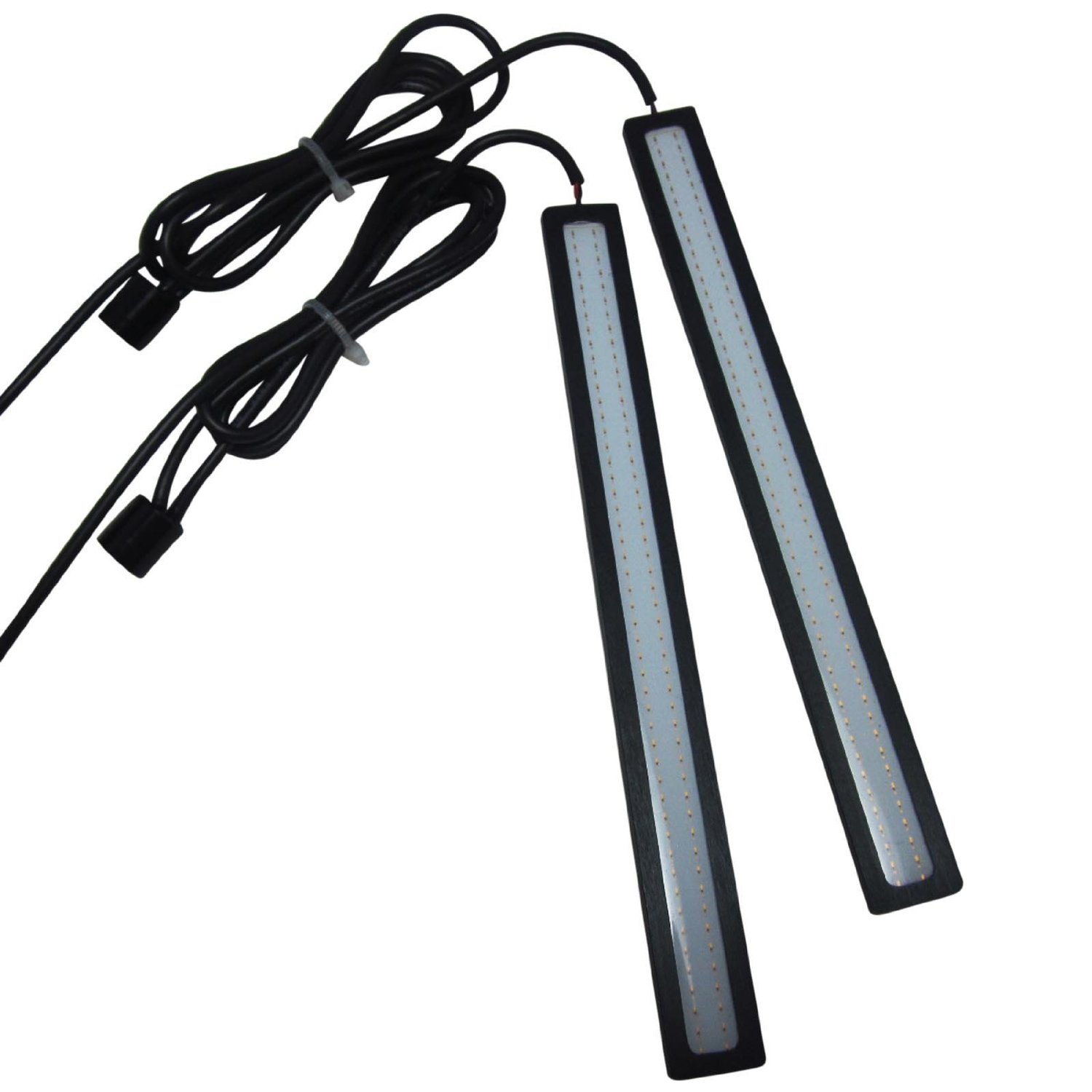
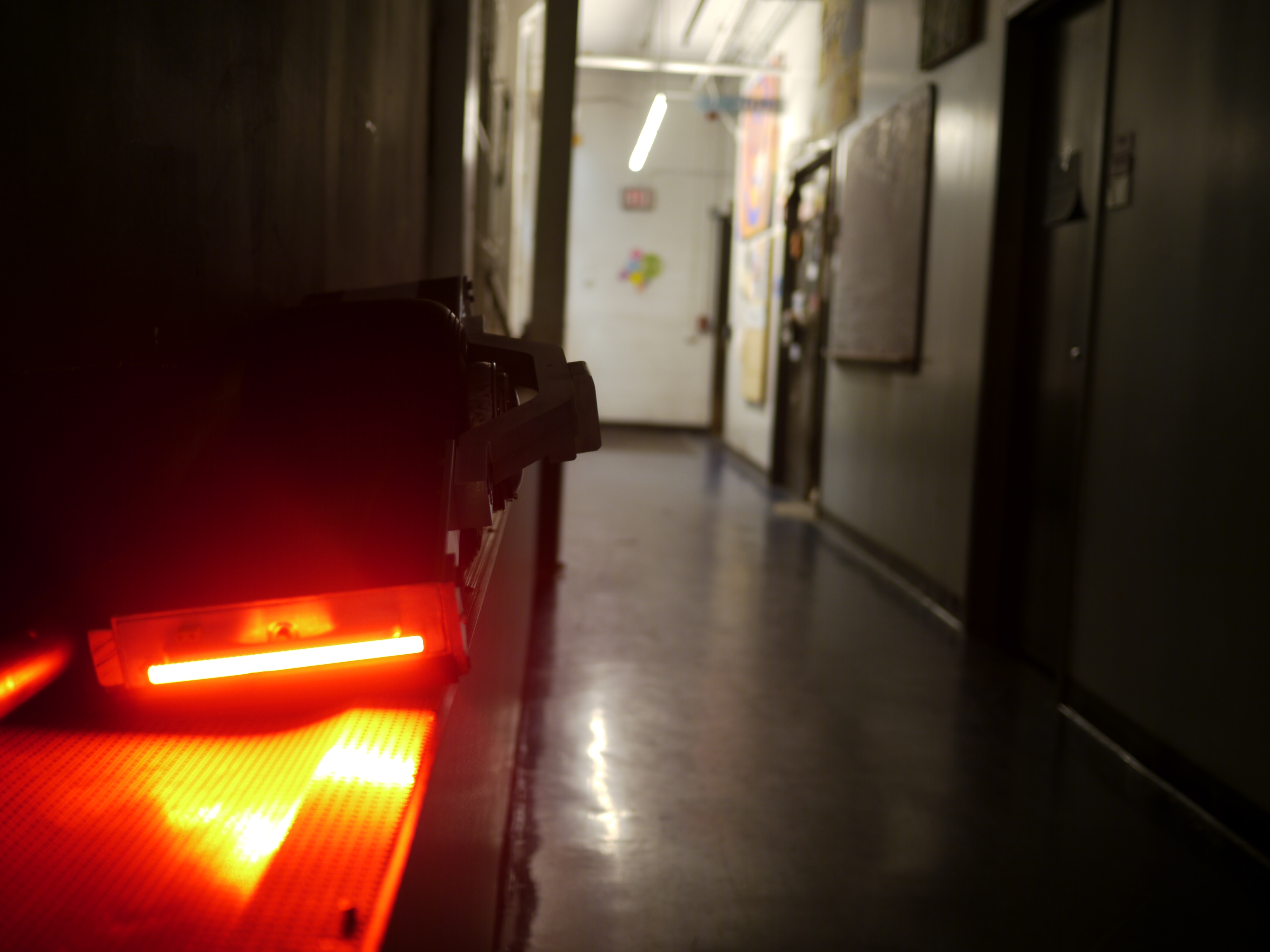
| The
red tail light [link] I looked for a 'dense' led strip for the rear of the skateboard and i found the above. Its 12V, so feeding power from the control board back over was needed. For this first setup, a 12v dc/dc was used tied to the battery pack. This is unfortunately not terribly ideal, as the under voltage cutoff of that dc/dc is ~16v. If the led is left on, it would drain to a non-recoverable state. Ideally these would get routed power from the control part of the chassis. |
 |
 |
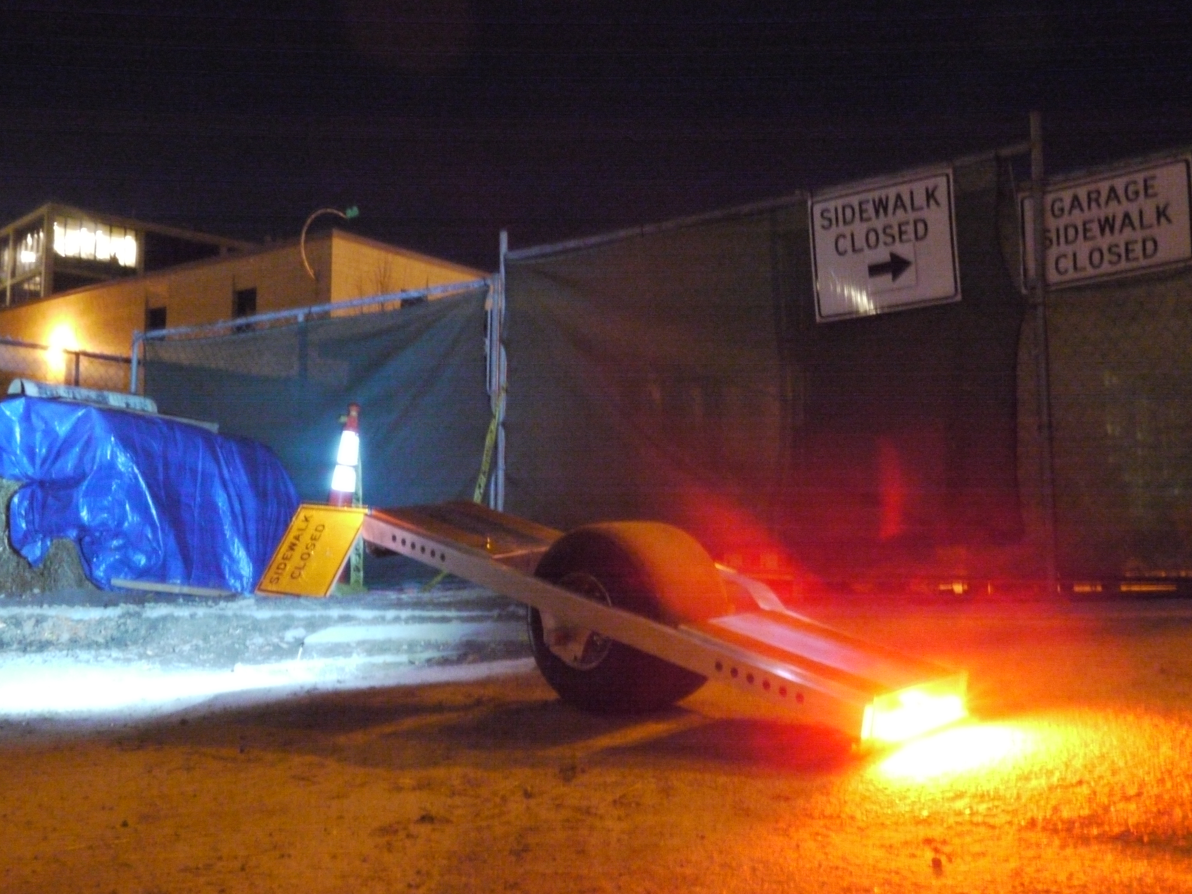
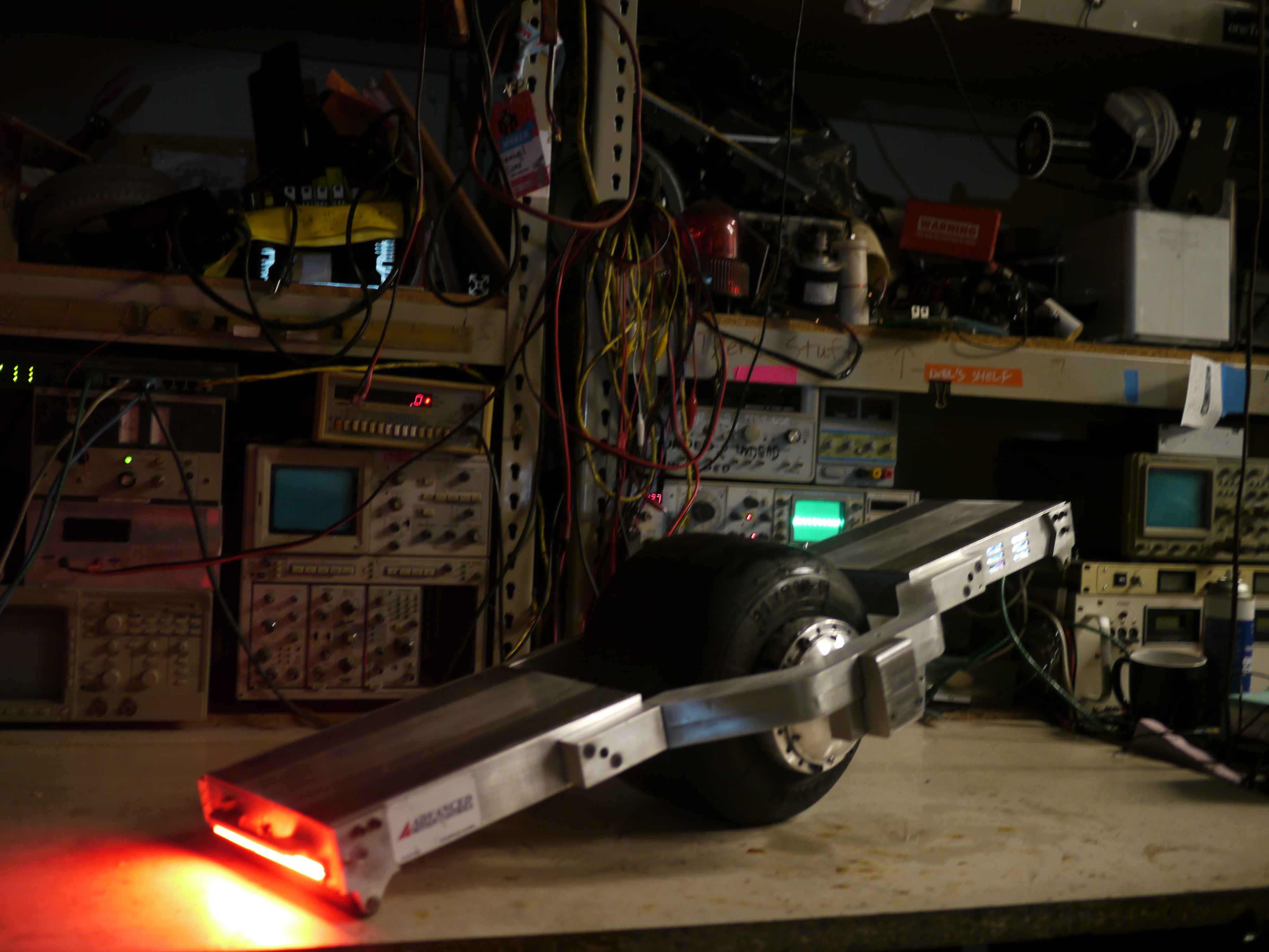
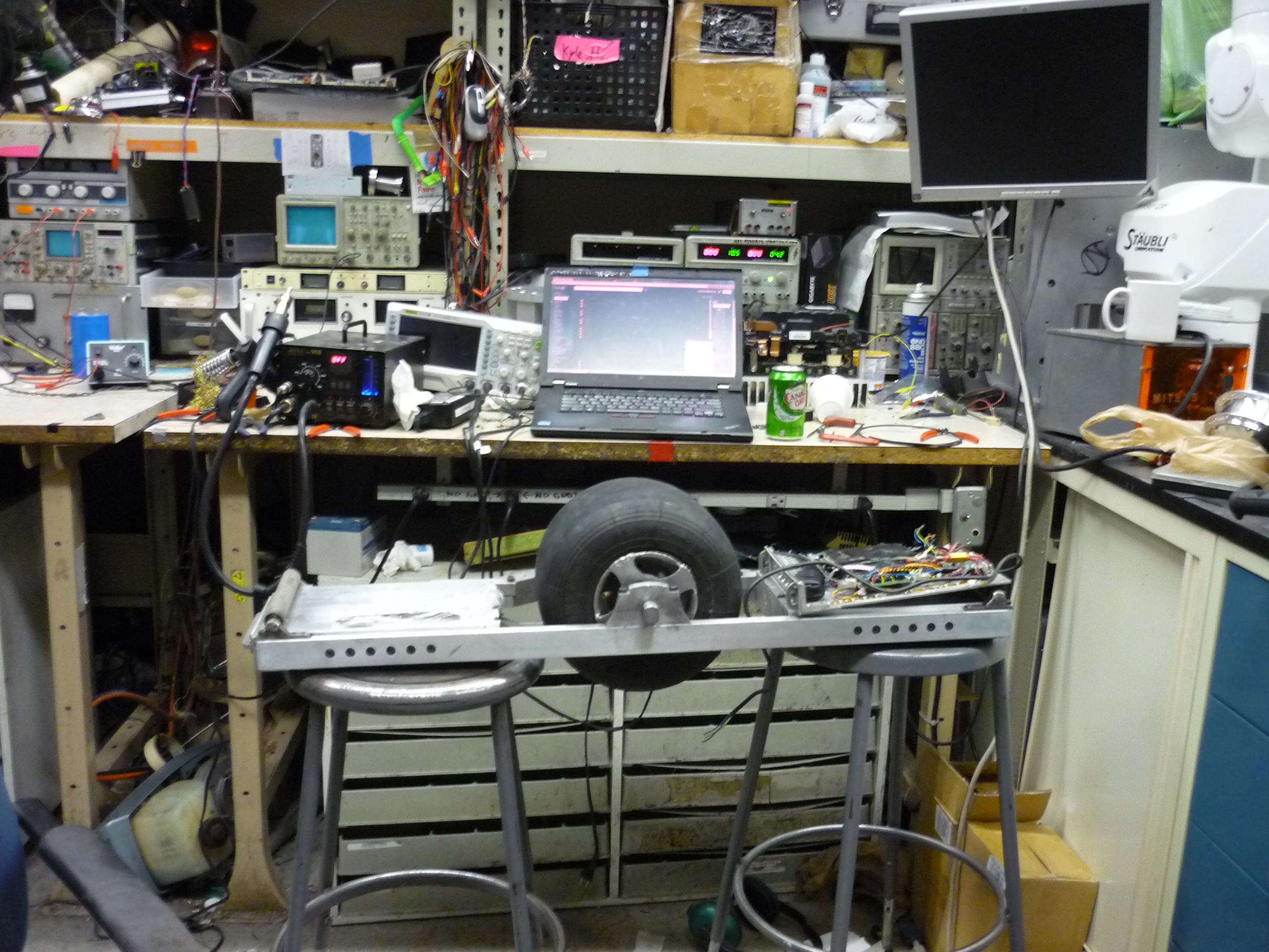
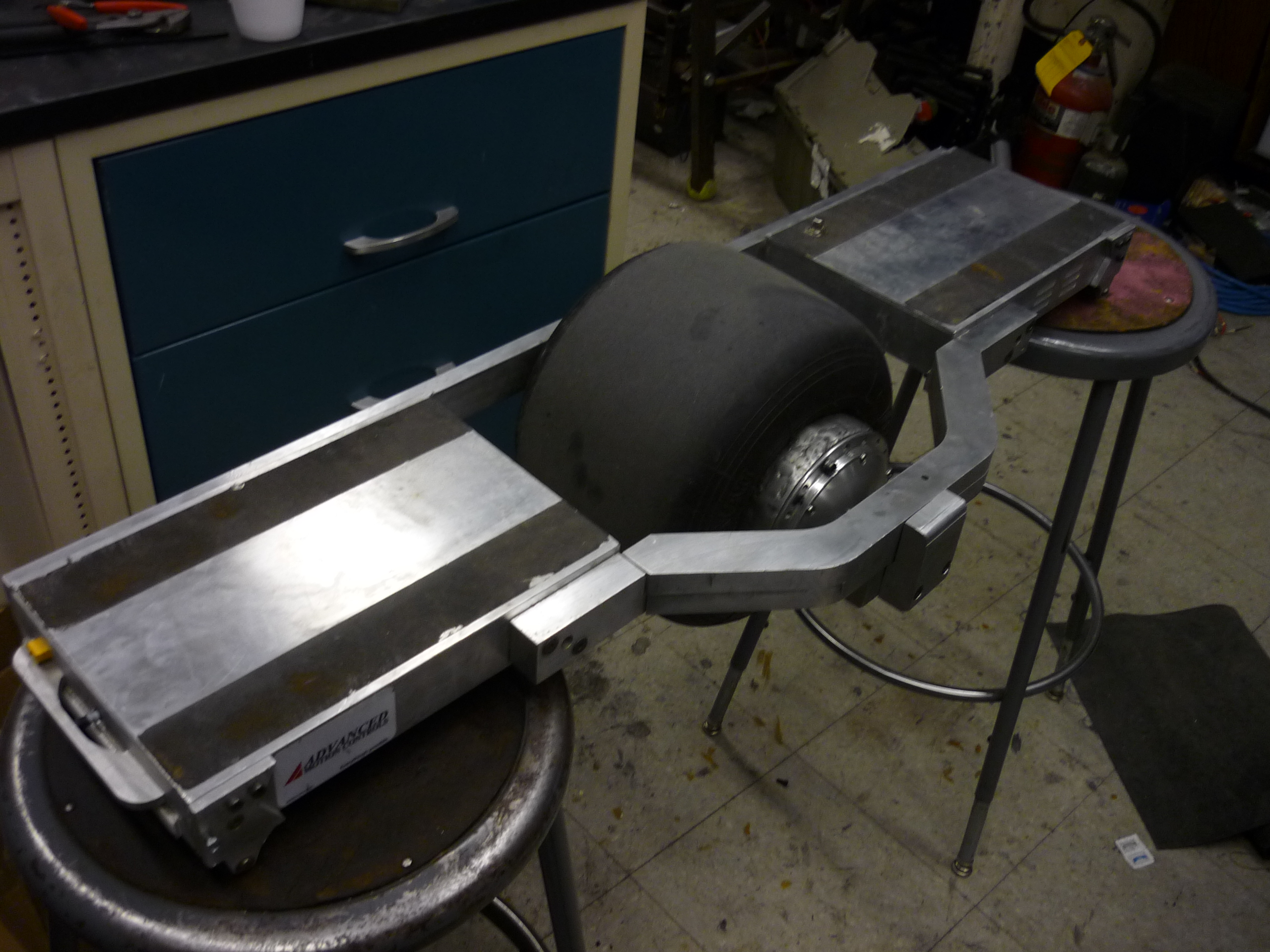
| SWANKY The upgraded nimbus sitting @ MITERS. The rear LED draws a boatload of power, and heats-up accordingly. Its blinding at night, and definatley keeps up the 'what the heck is that thing' effect. |
 |
 |

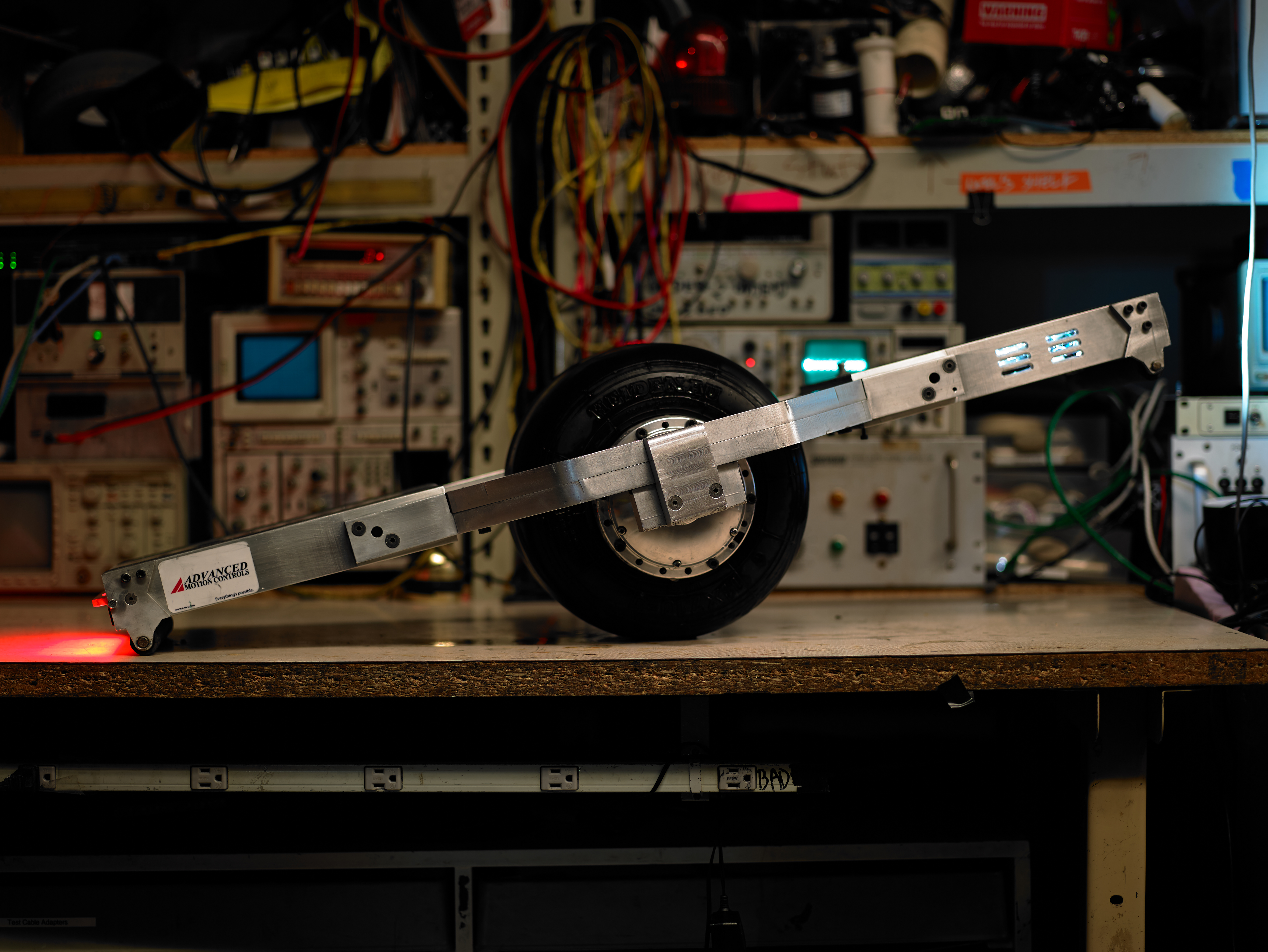
| Wheel Upgrade | ||
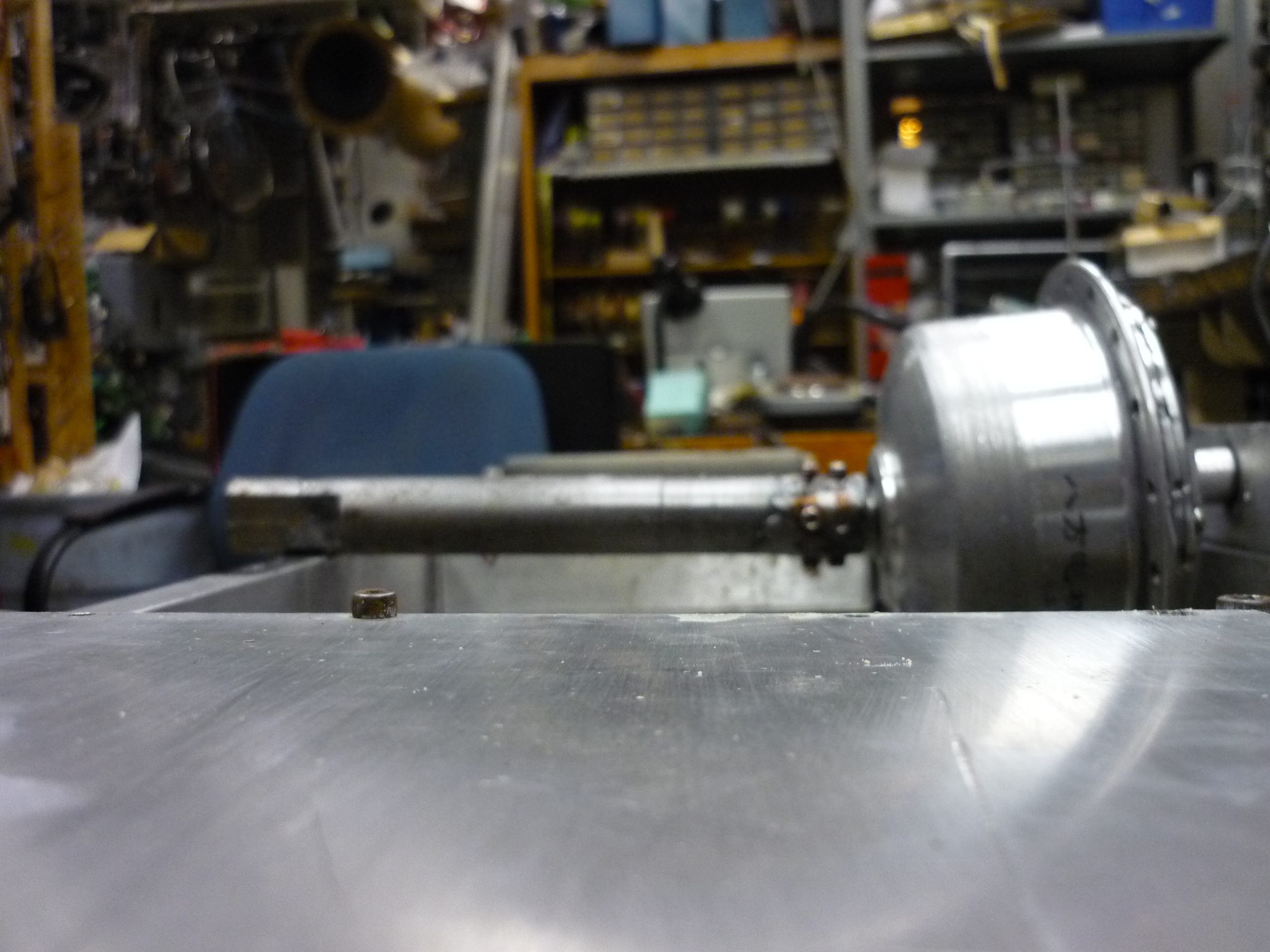
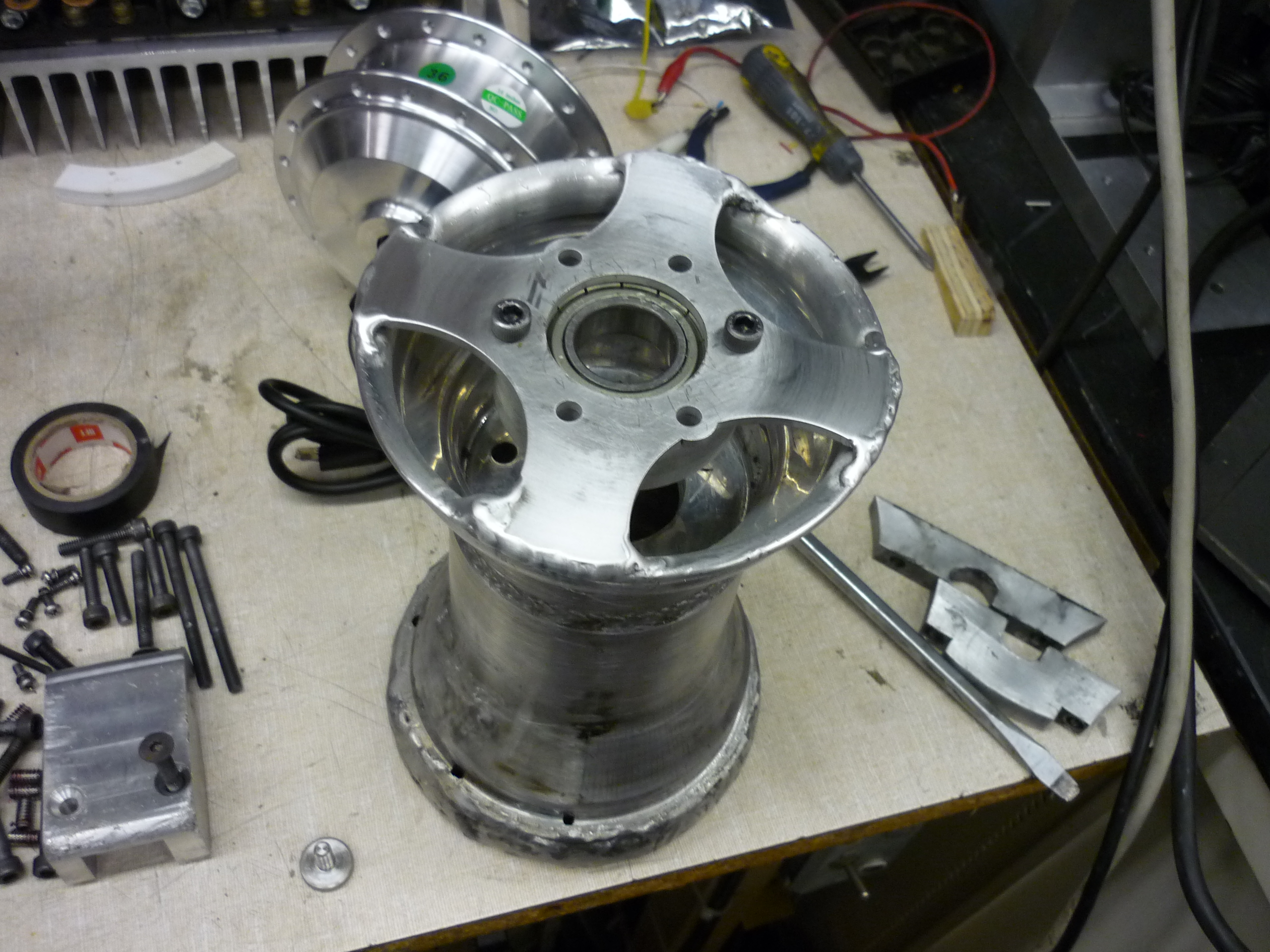
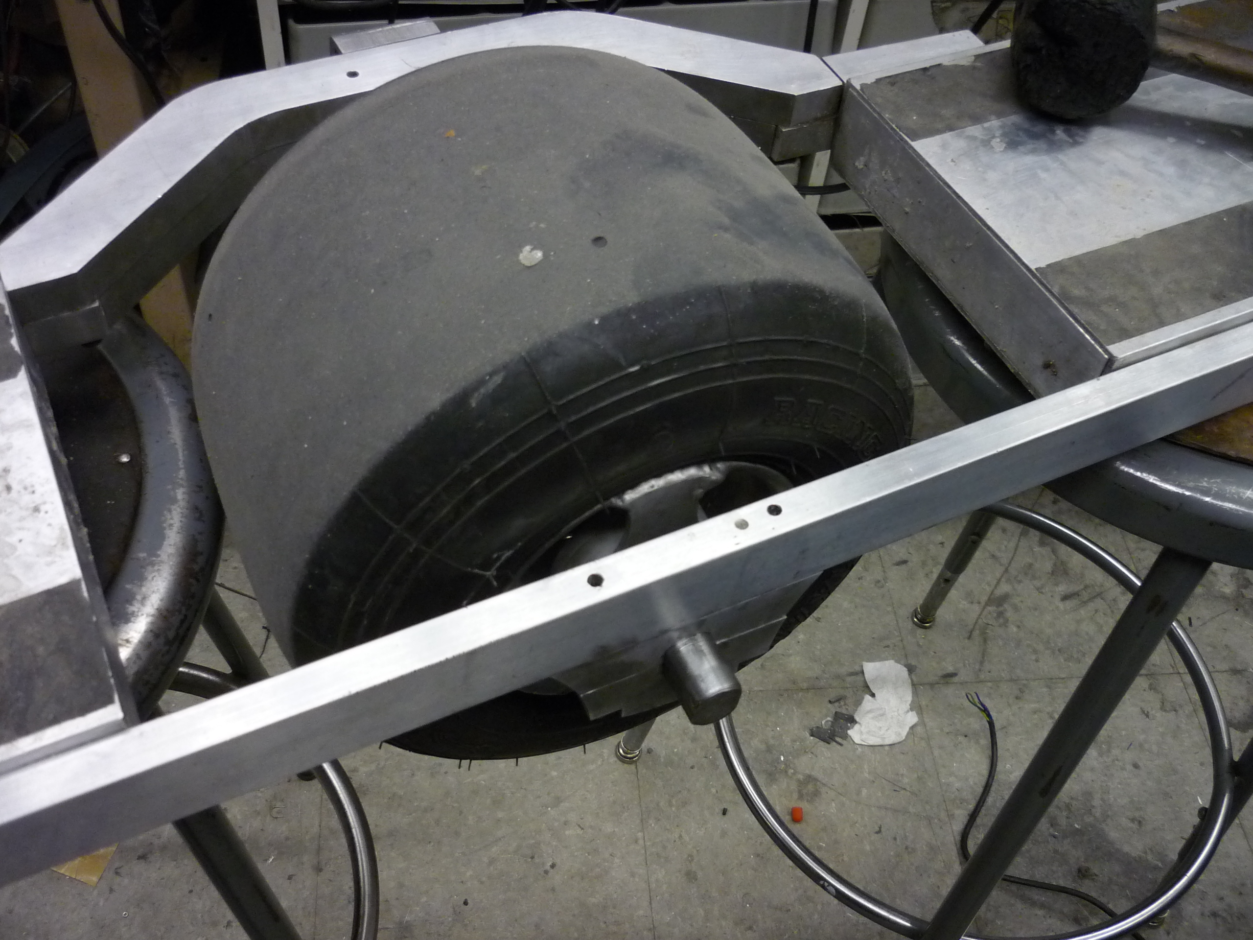
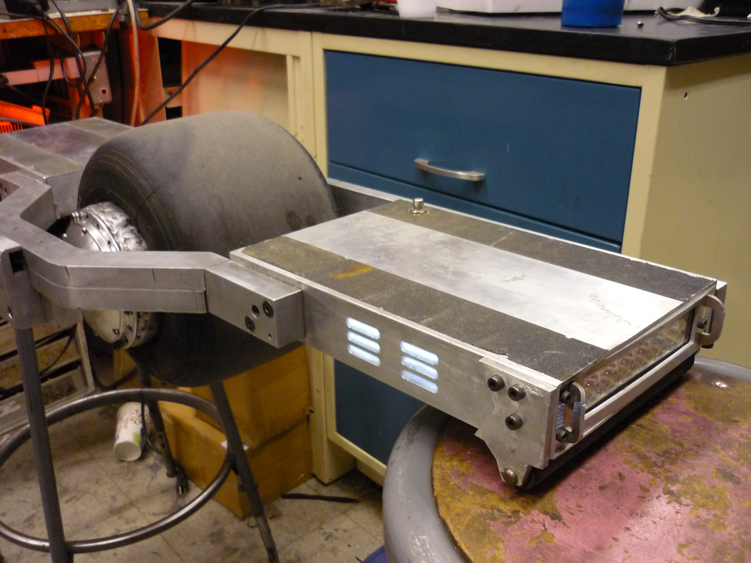
| The wheel itself actually has a bit of a design flaw, the support for the furthest side of the wheel is lacking, creating a small offset in the loading on the rim. This causes the mating between the motor and the frame to flex over time. In order to compensate for this, a wheel-mating feature was devised. Attached directly to the rim, it should provide the required support and constrain offset loading. |  |
 |
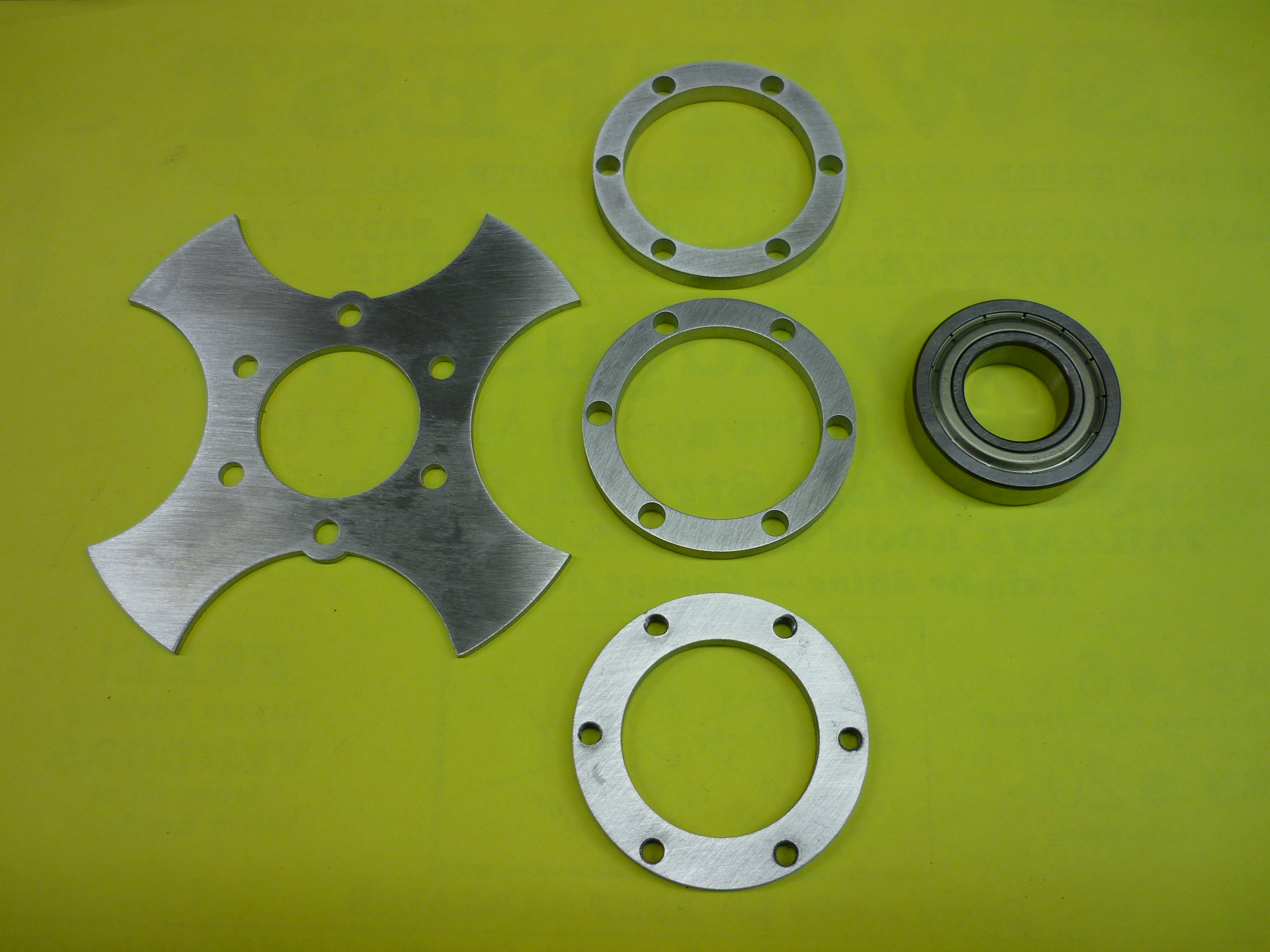
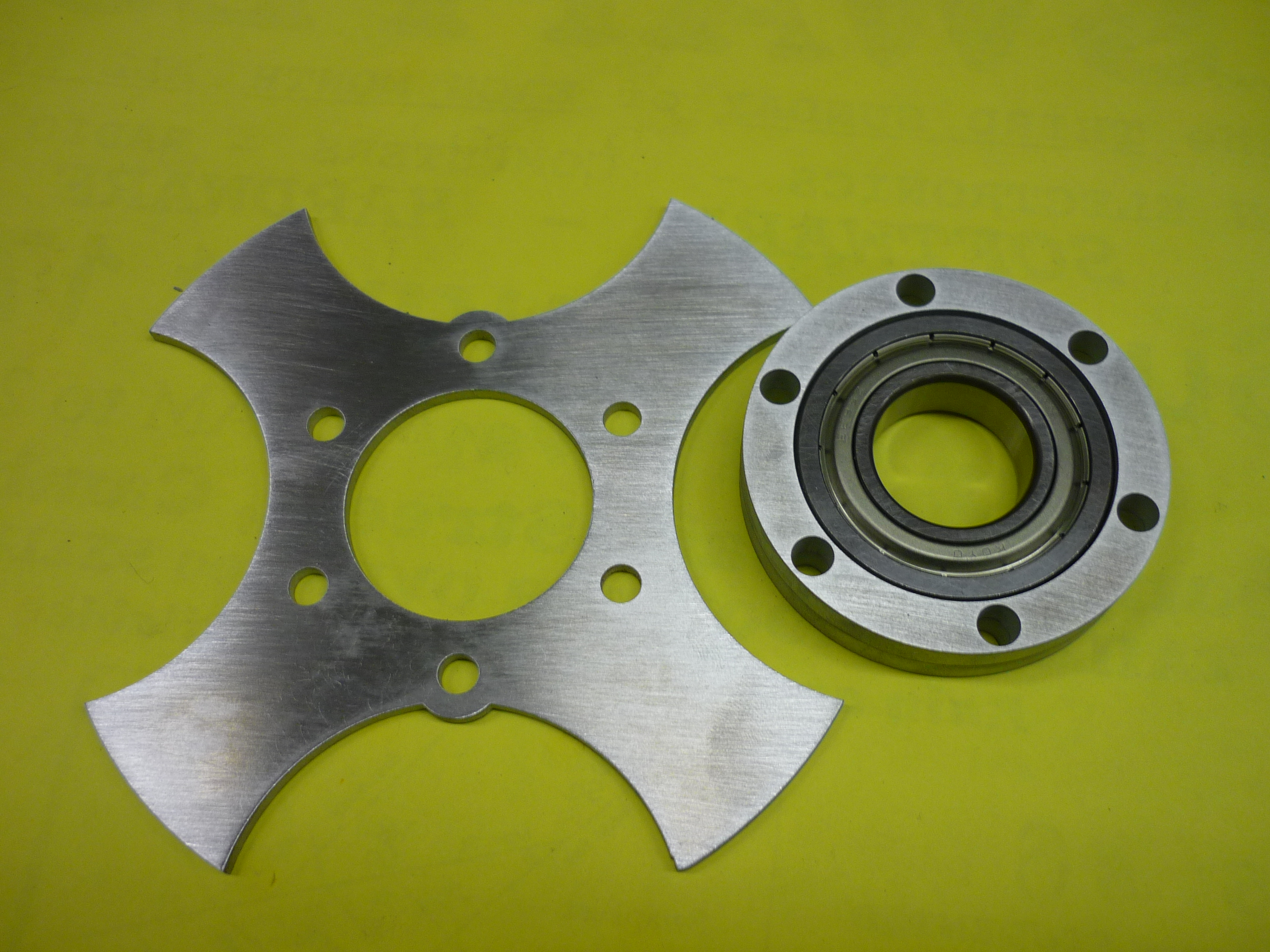
| Waterjet
Time! After some setup, and making use of the scraps of 1/4" 6061 aluminum I've been collecting. The purpose of the 'X' style of the rim adapter was twofold. The scrap i had wasnt big enough for a full circle, and the tire valve stem still needed a way to reach the outside world. |
 |
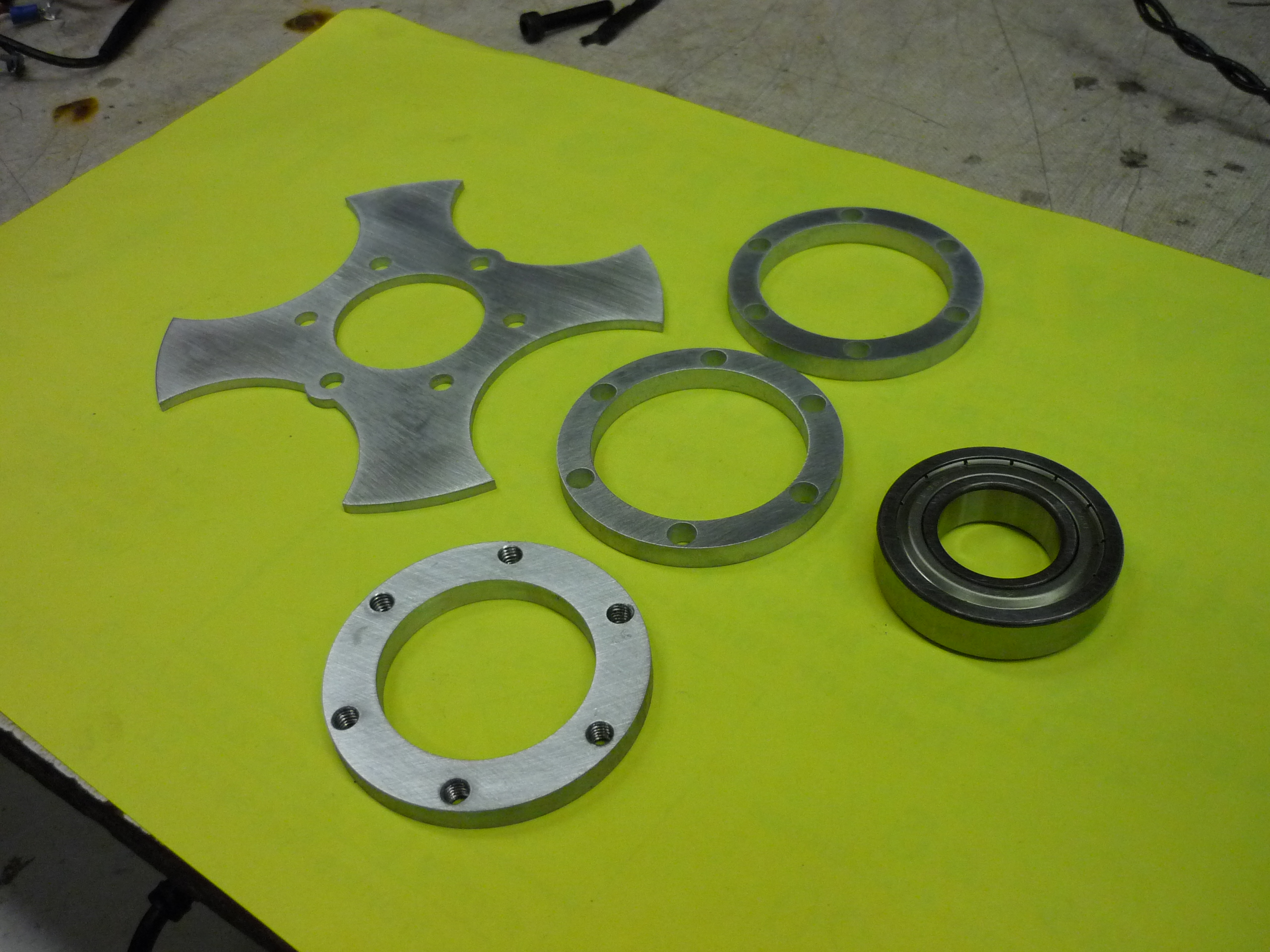 |
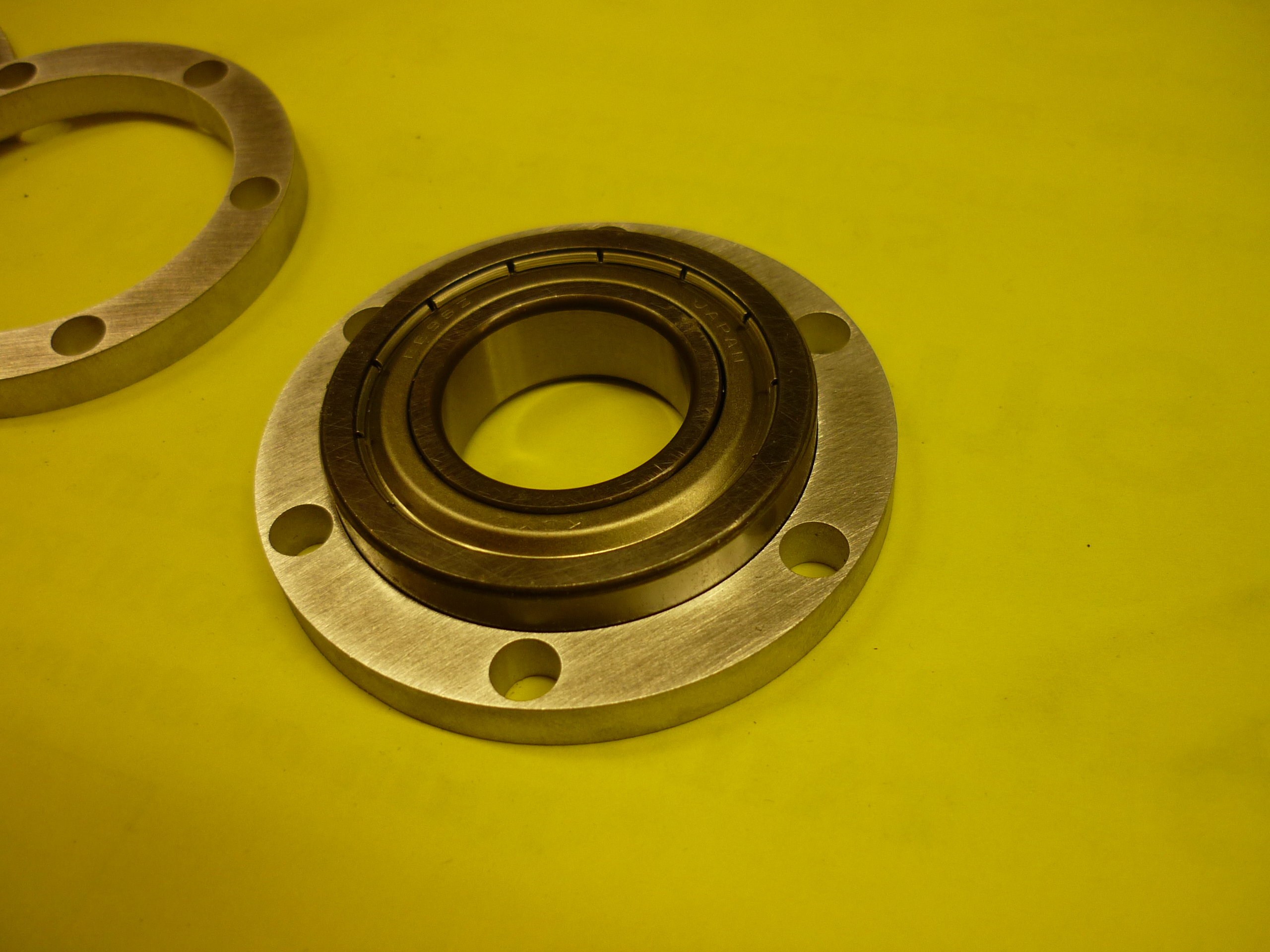
| Bearing
inset Fits like a glove. The bearing holsters are cut so that the M6 bolt passes through, while the cuts for the top plate are sized for an M6 Tap. The tapped ring has more material available for the screw to grab into, whereas the spacer rings come fairly close to the bearing material. |
 |
 |
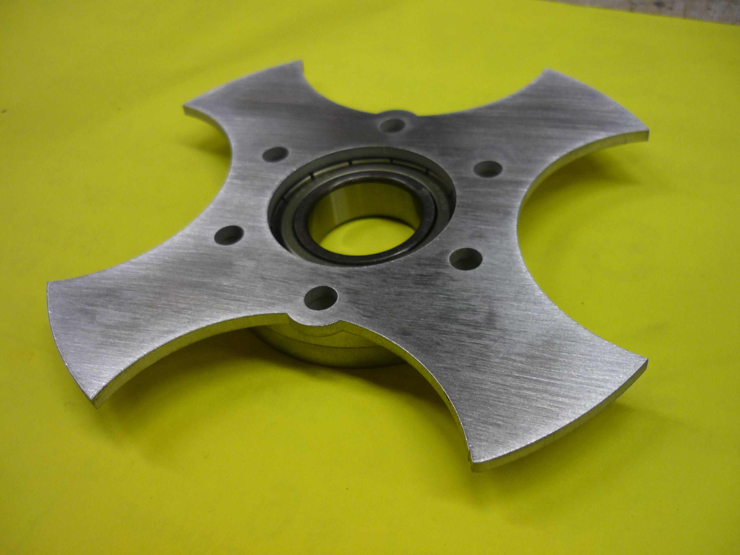
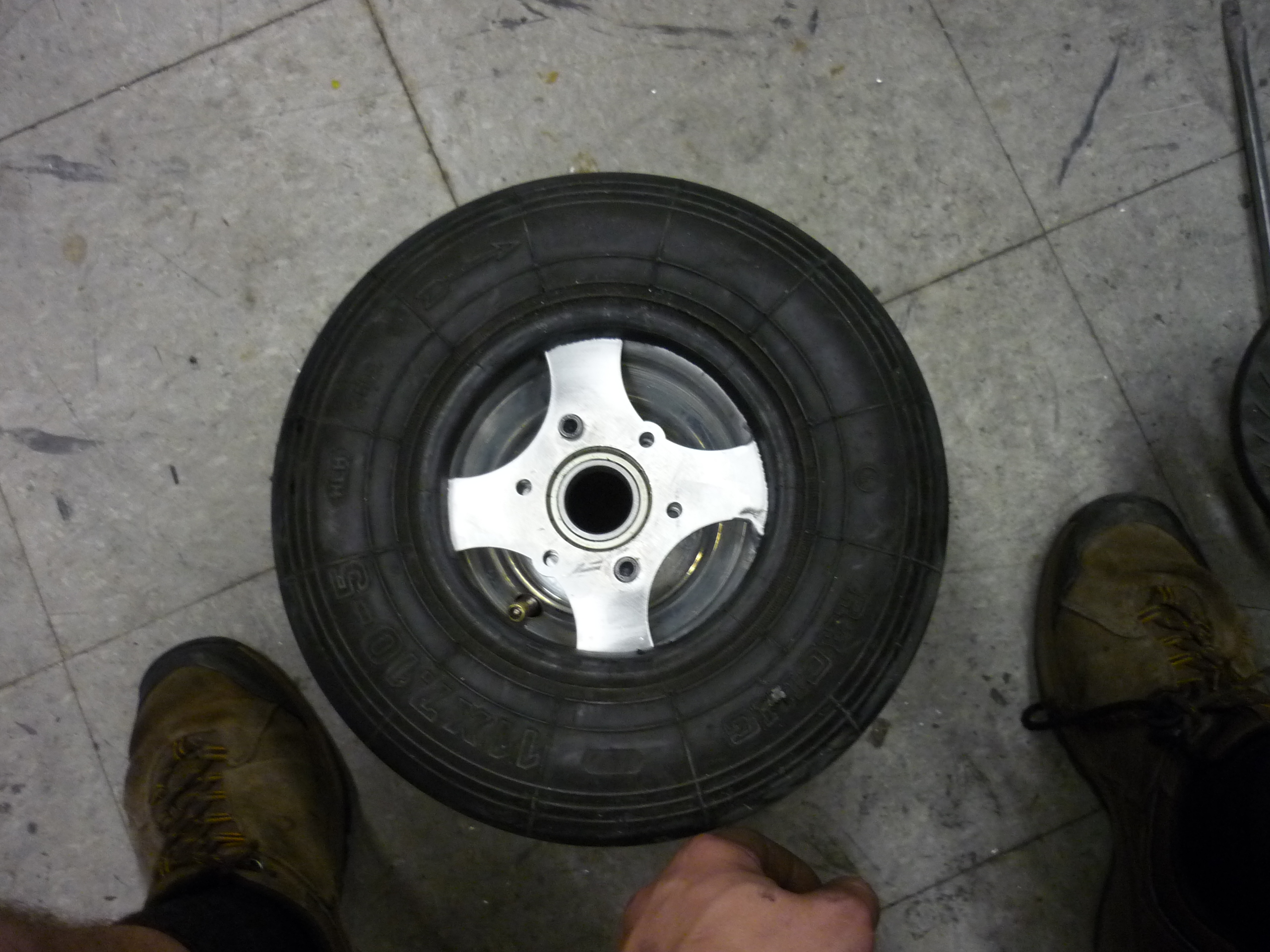
| Assembled The bearing [link] fits well in its new home. The end plate is tapped for M6. Shown, 2 bolts hold everything in place. |
 |
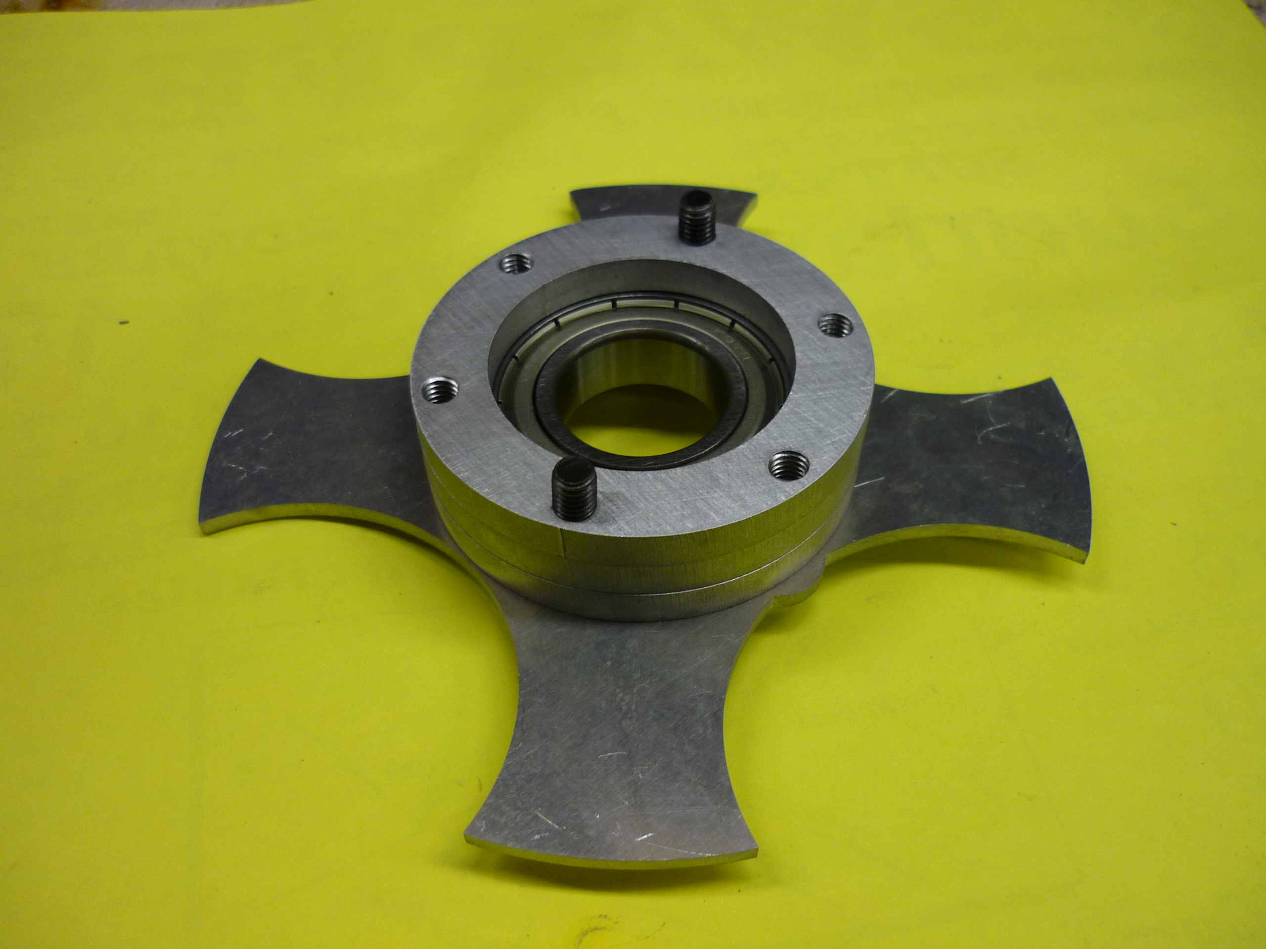 |
| Welded
bearing insert After some quick tig-welding, the bearing insert sits on top of the wheel hub. Pre-heating was key to get some decent welds. |
 |
 |
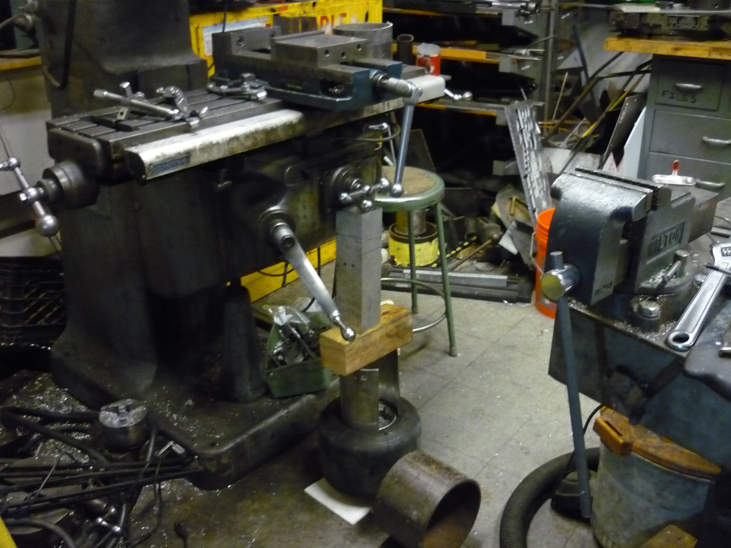
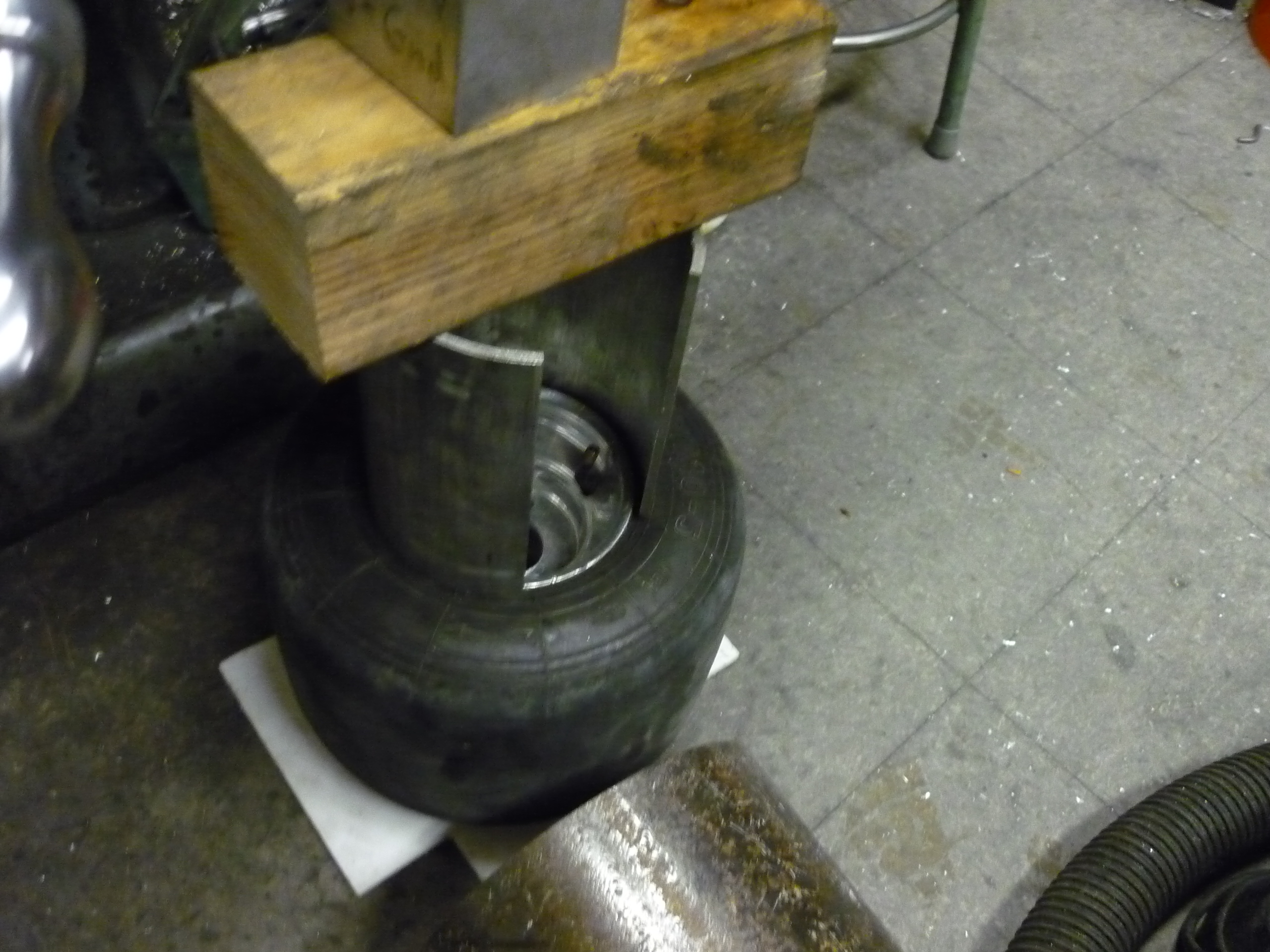
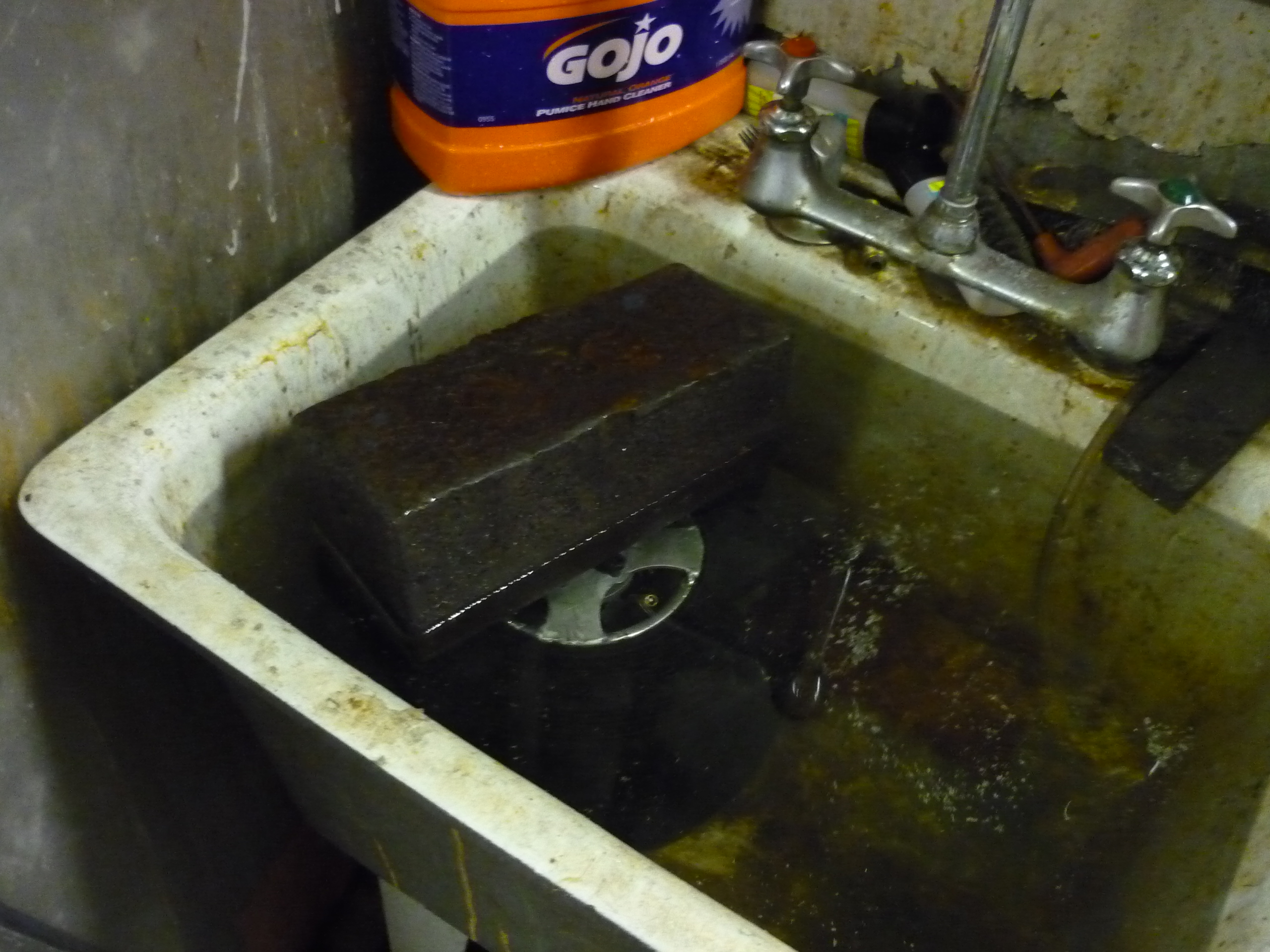
| Shoving
in the tire & Leak Test It took a lot of screwdriver + force to fit the tire back in place. Both myself, krikby and peter were needed to get this beast in place. Many thanks for the help! The sink was used to test if the tube was punctured in the process of installing the tire. No bubbles (or at least no super serious leak) |
 |
 |
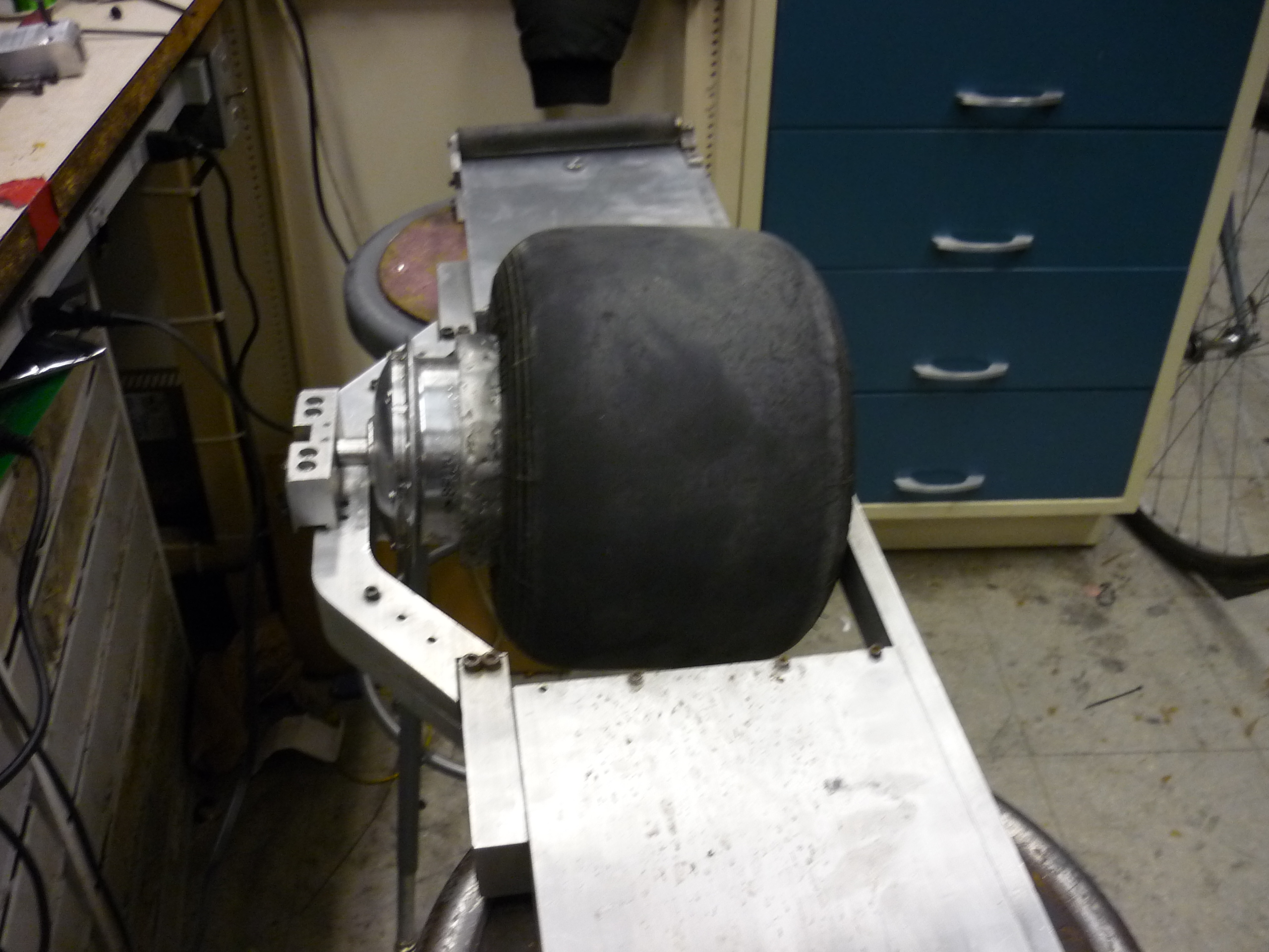
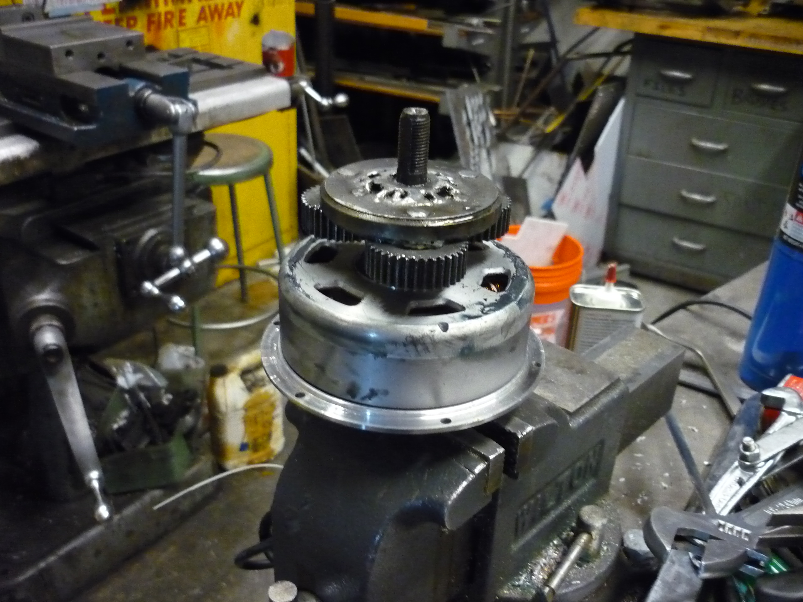
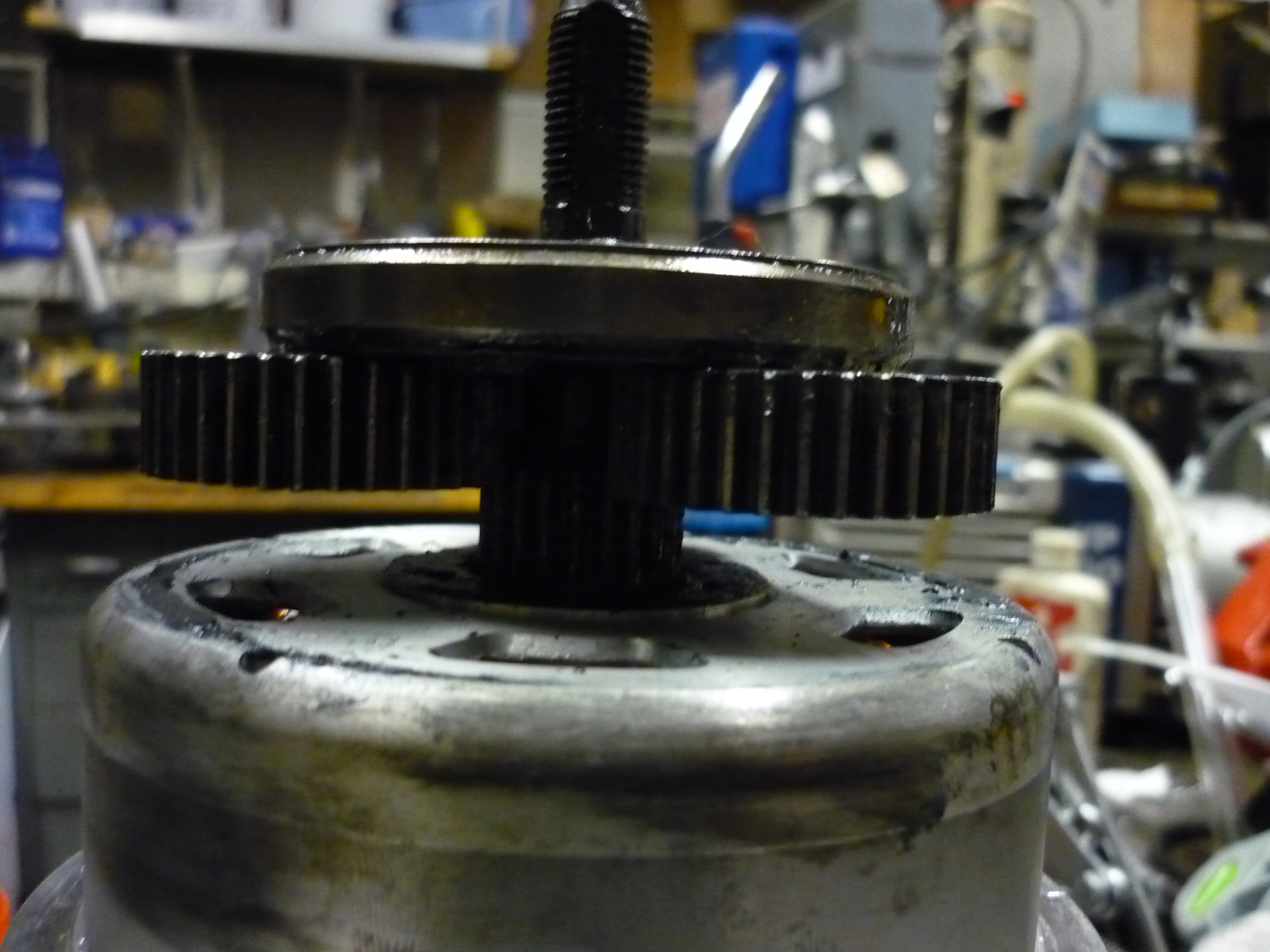
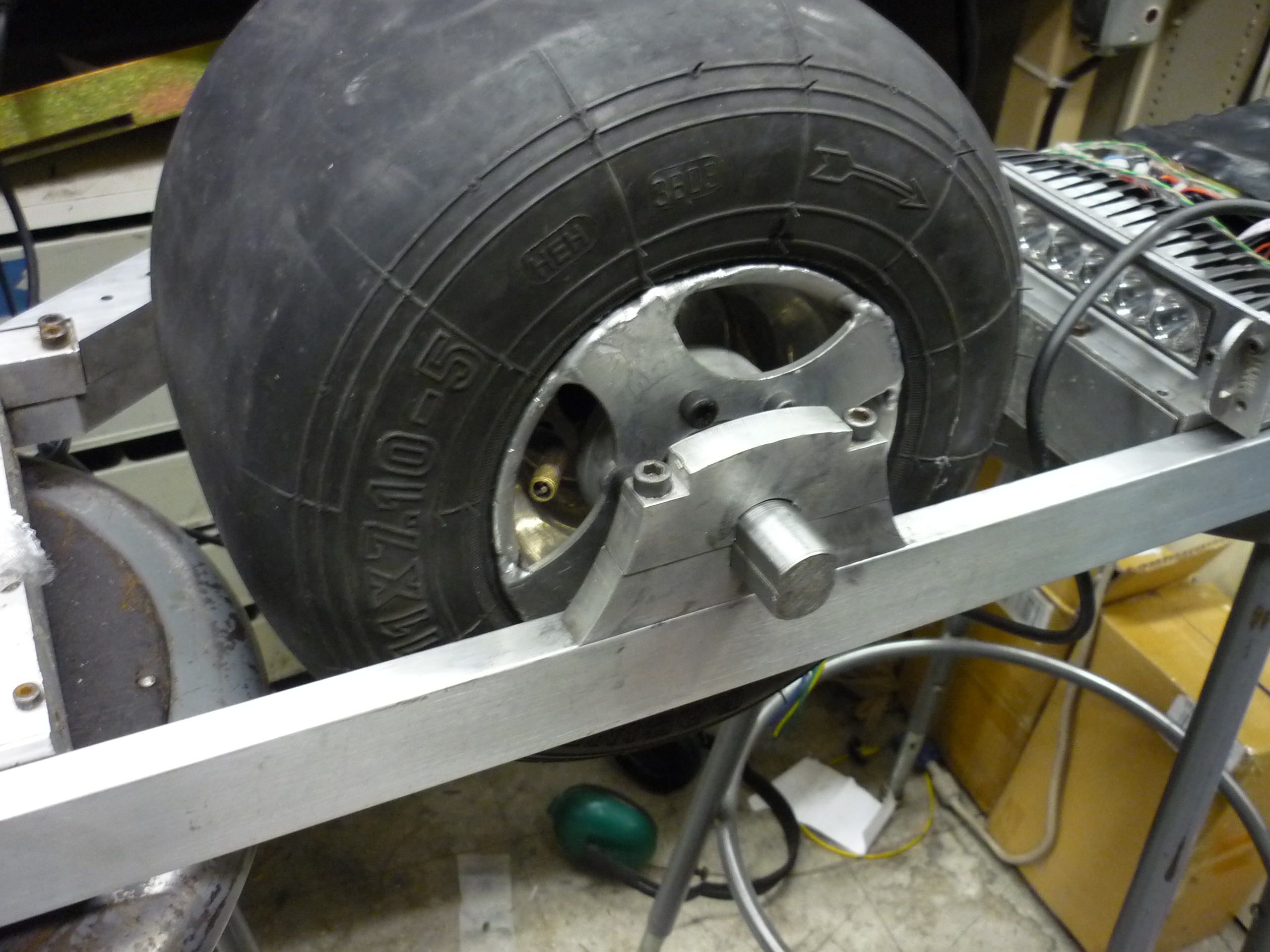
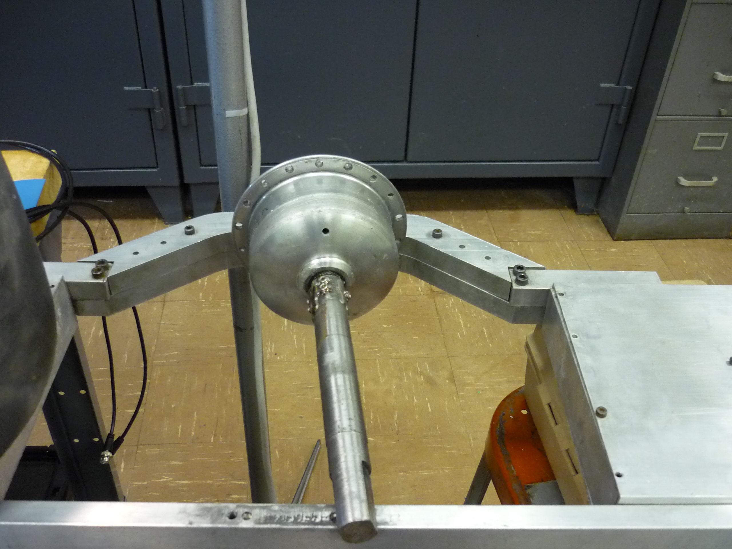
| Putting
it all together The hub motor and shaft adapter are attached to the hub motor and the new bearing plate clears the side mount. |
 |
 |
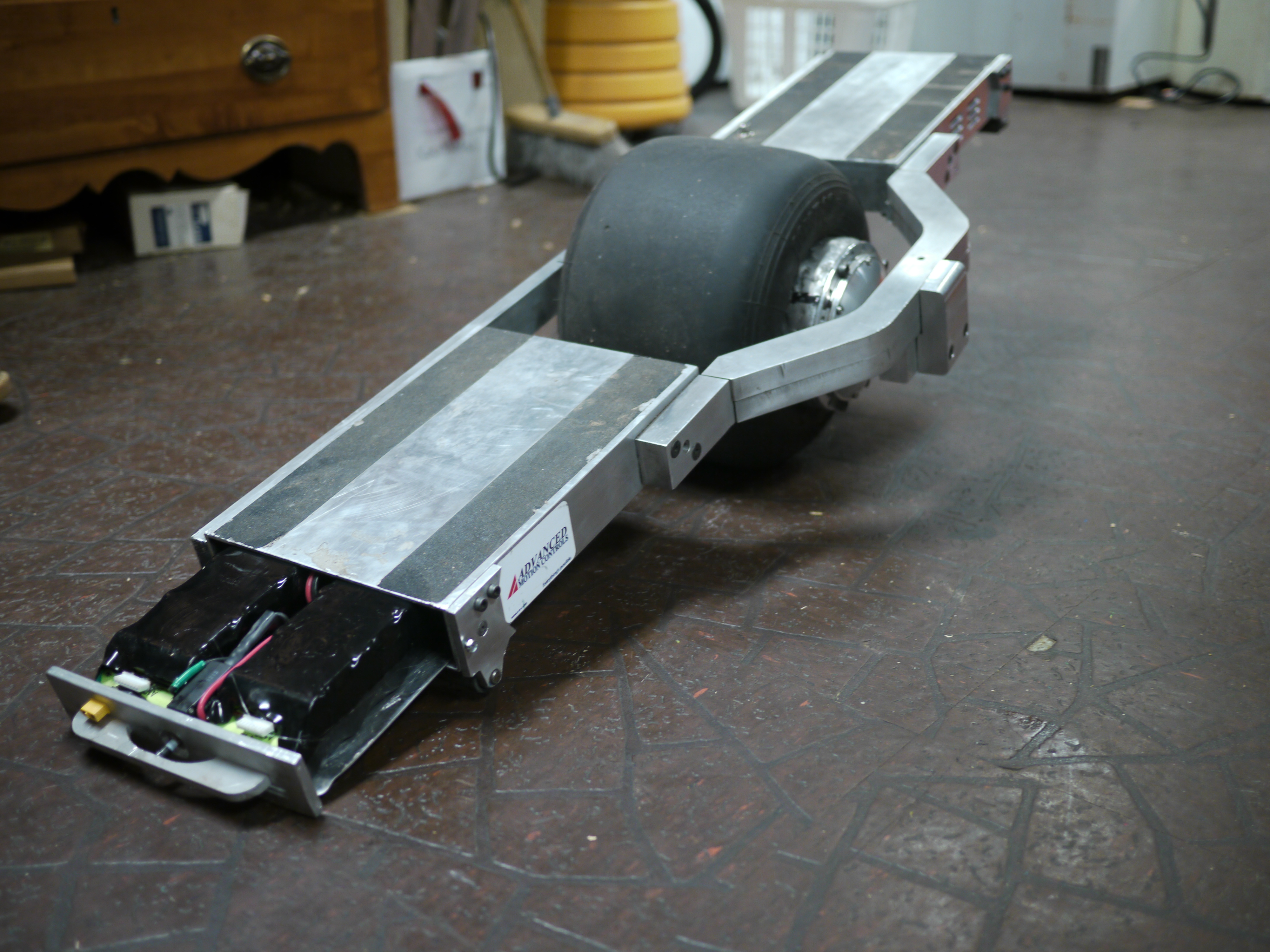
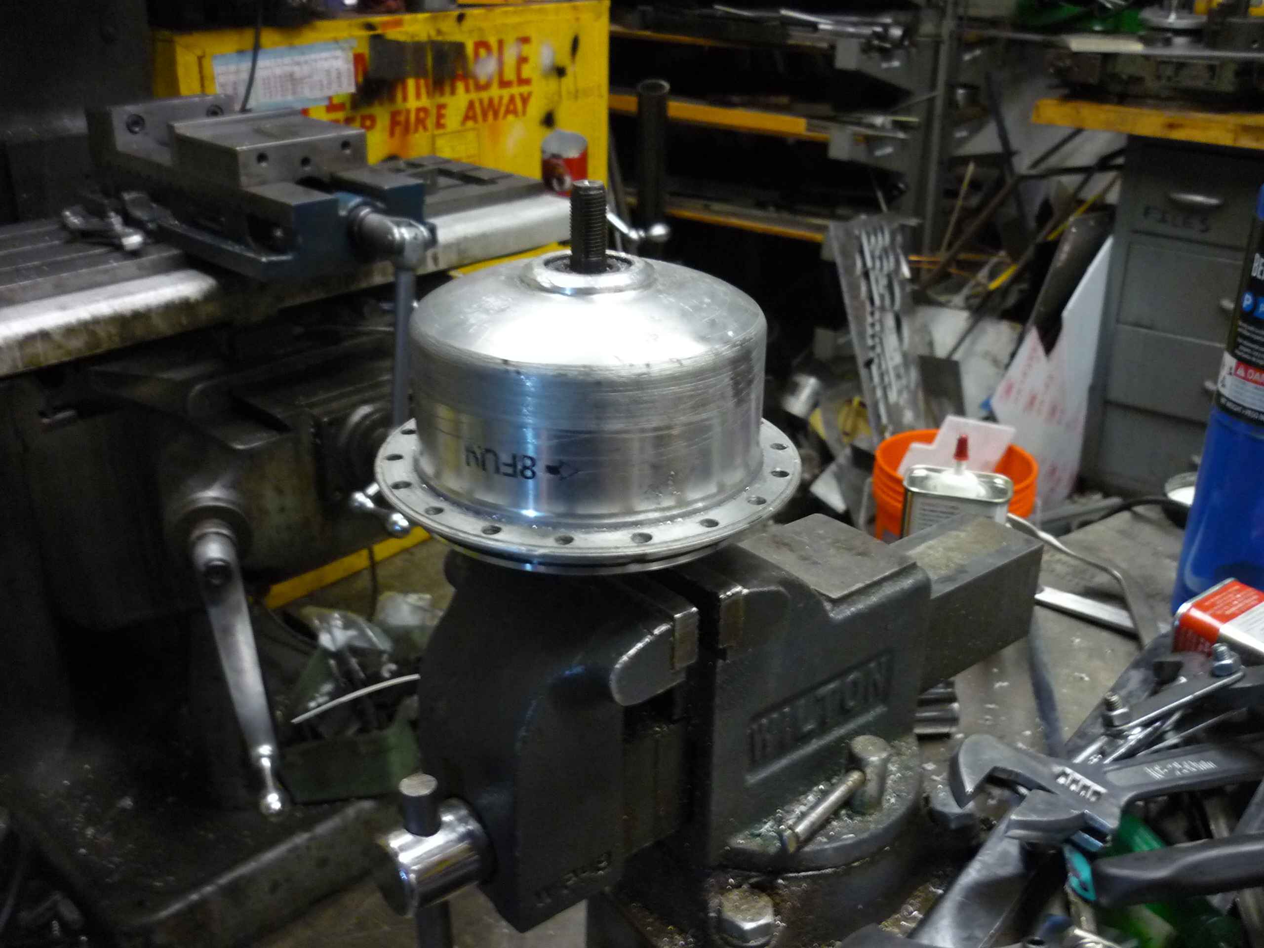
| Re-mounting, re-cabling and ready
to rock. After completing the rim modifications (listed below) the tire was re-seated, re-inflated and everything was quickly shoved back together. |
 |
 |
| Sealing and Adding A Grease Fitting | ||
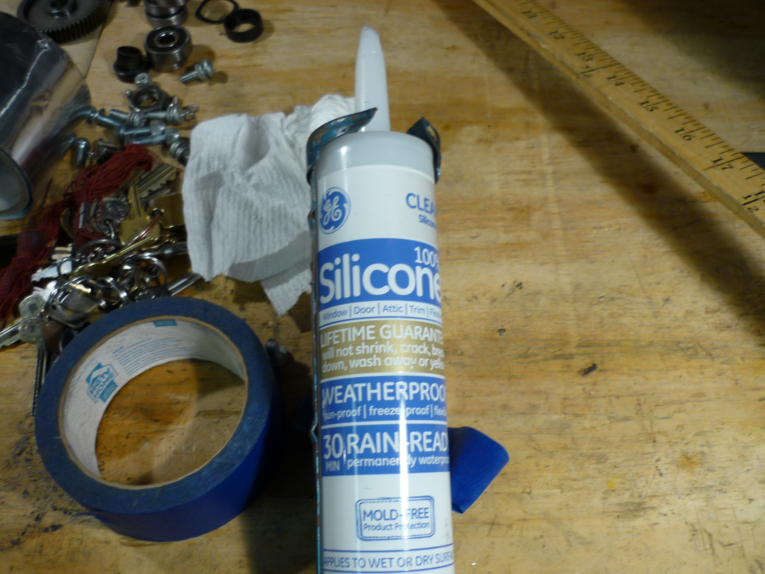
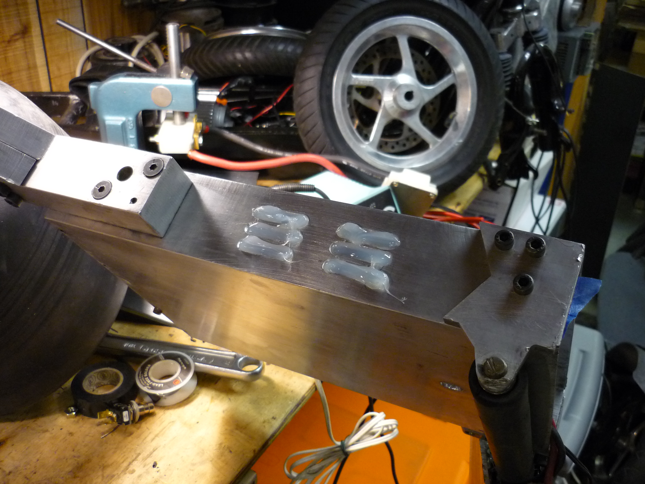
| Waterproofing
the vent. The vent holes, documented earlier, were intended to allow airflow to the controller. Fortunatley the super-swanky AMC controller's dissapation is fairly low, and all the vent does now is let mositure in. To fix this, i used some housing-silicone goo and painters tape. The inside of the skateboard is covered to prevent the goo from leaking in. The silicone was applied to the outside in thick beads. |
 |
 |
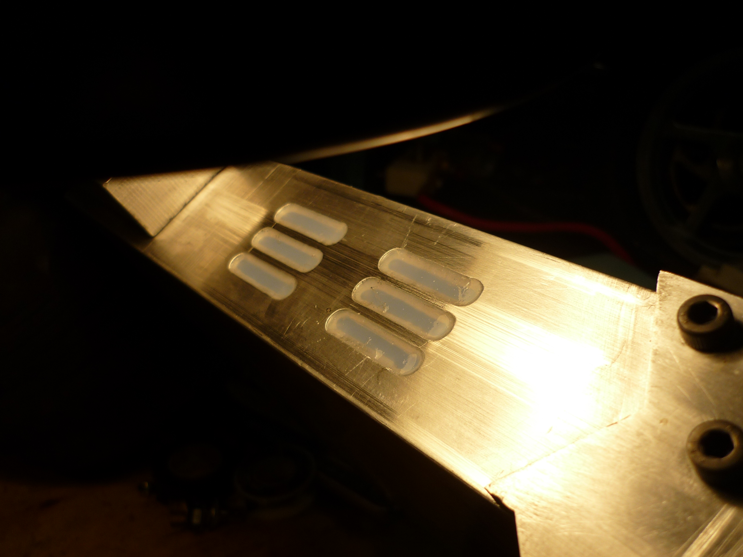
| Goop
on that silicone After letting the silicon sit for a minute, a sharp utility-knife blade was used to scrape the surface flat. |
 |
 |
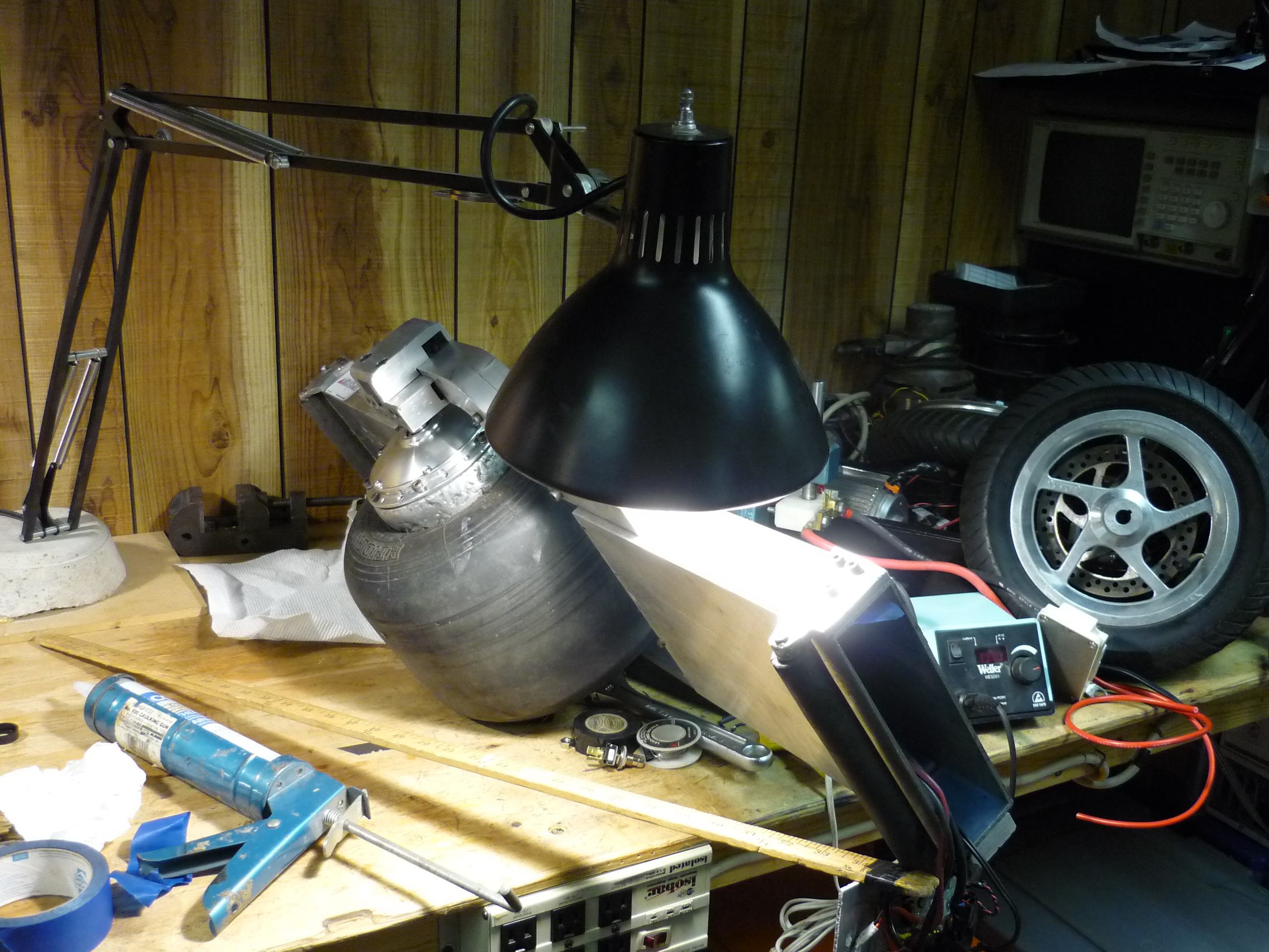
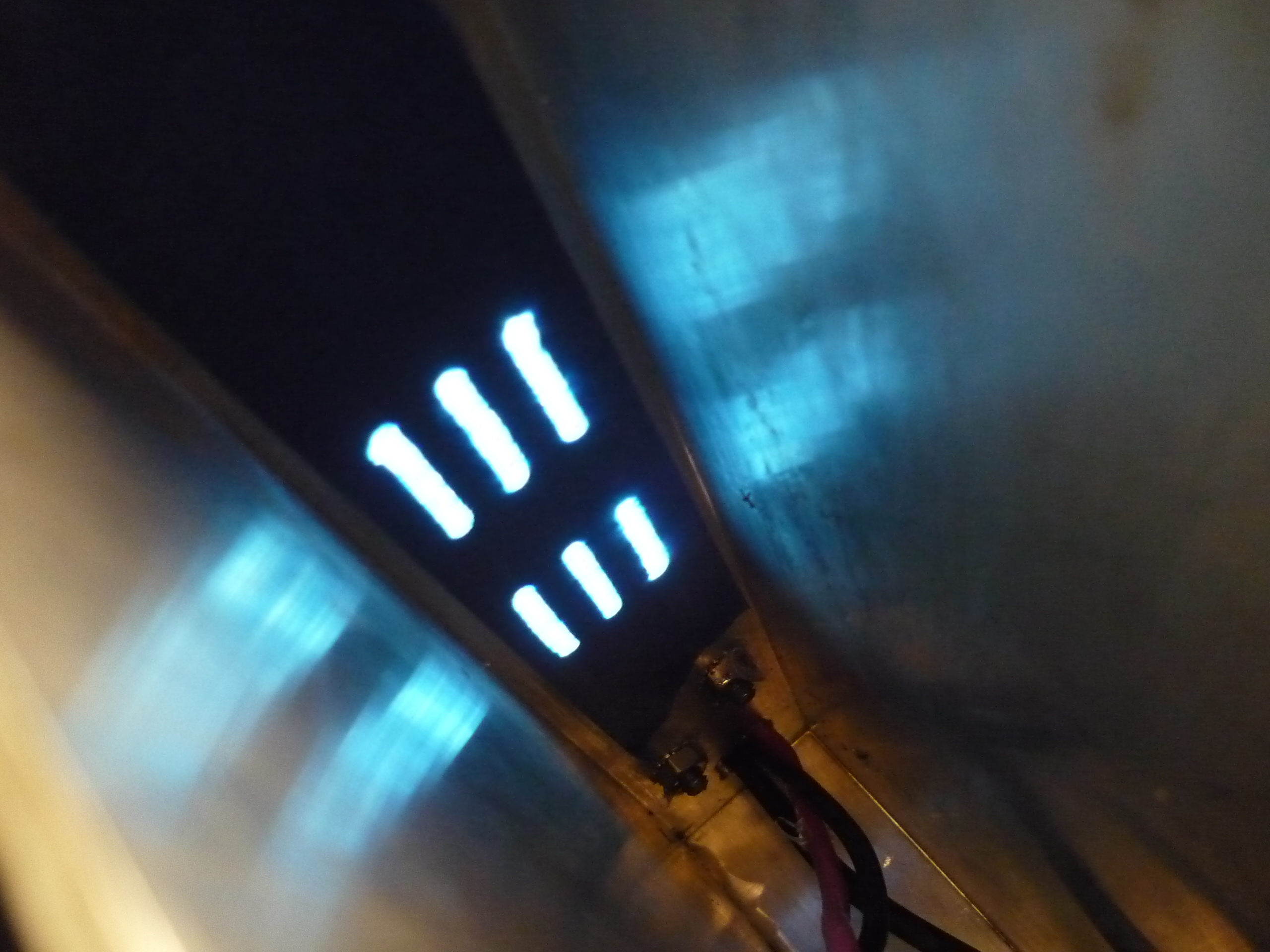
| ACCELERATING
SCIENCE Using an incandescent lamp, next to the silicone, the drying is accelerated slightly. Shown (right) is the view inside through the tape. reference to: [link] |
 |
 |
| Time
for a grease fitting! A 0.20" diameter hole was drilled in the hub motor, and a 1/4-28 threaded grease fitting was added. This allows grease to be added to the wheel assembly planetary gear train. |
 |
 |
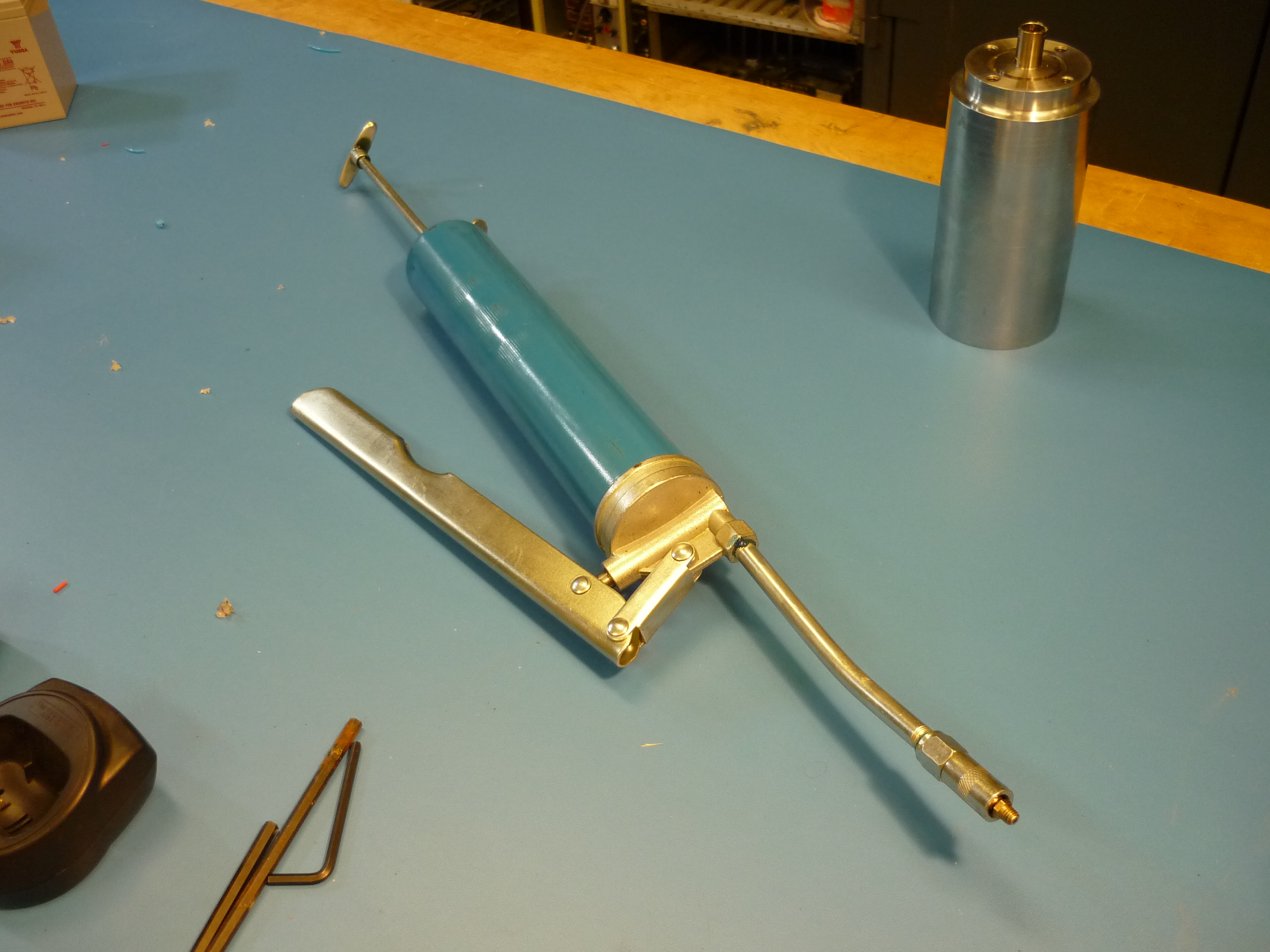
| GREASE
and allenkeys Shown (left) is the grease-gun and the re-assembled nimbus. After adding grease to the geartrain, it seemed to roll in a smoother, somewhat quiet-er fashion. |
 |
 |
| Backlash improvements. | ||
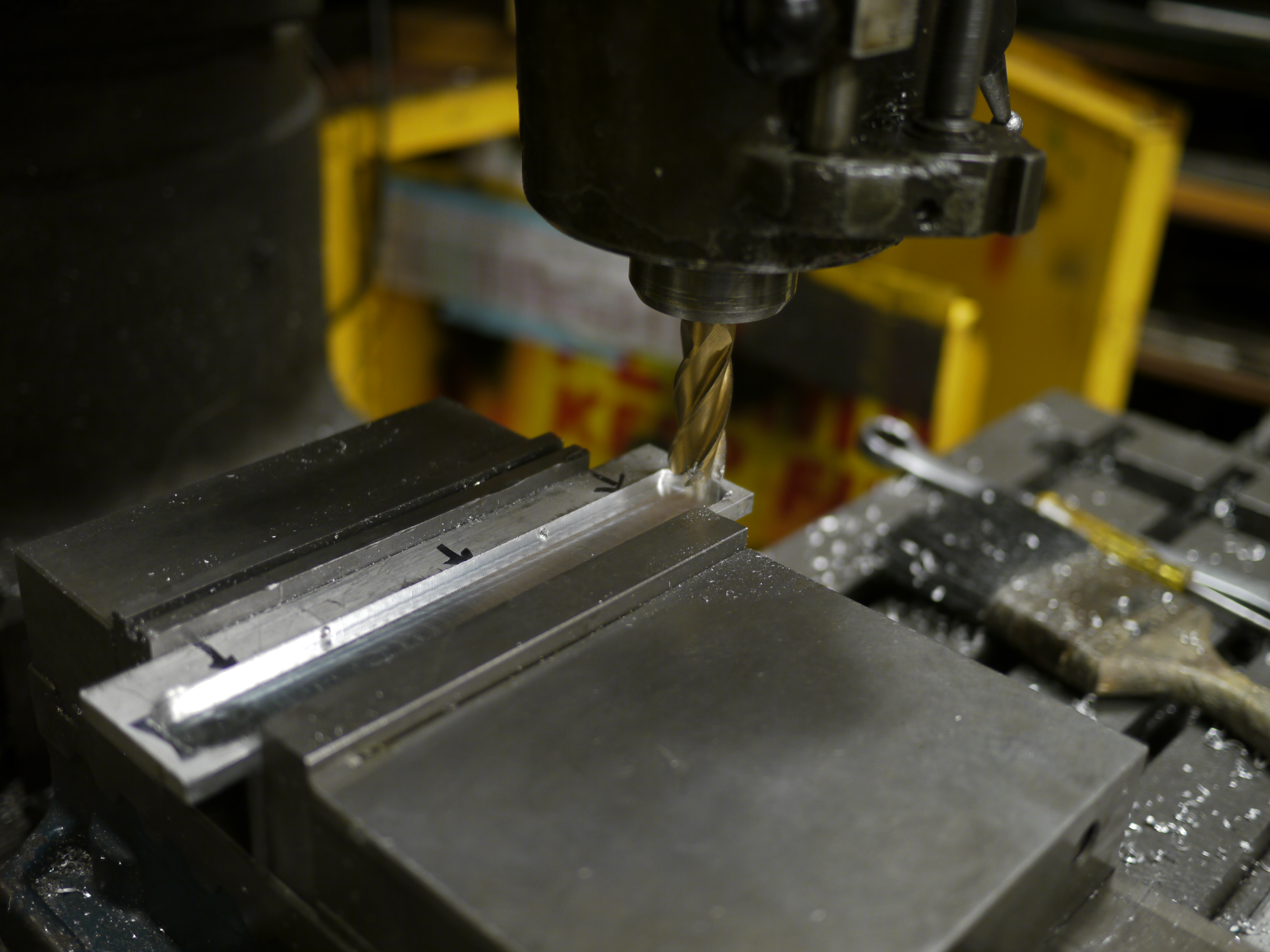
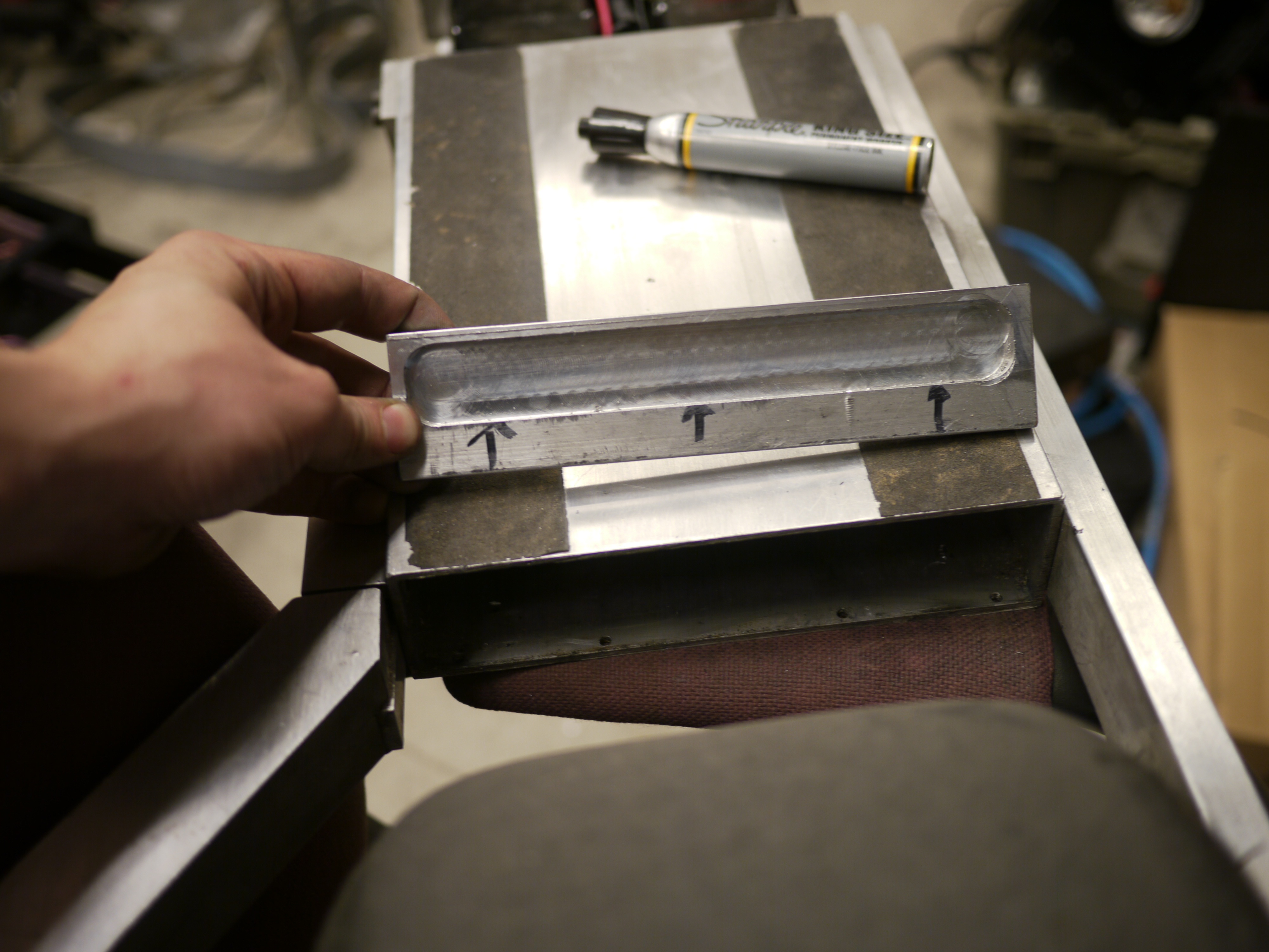
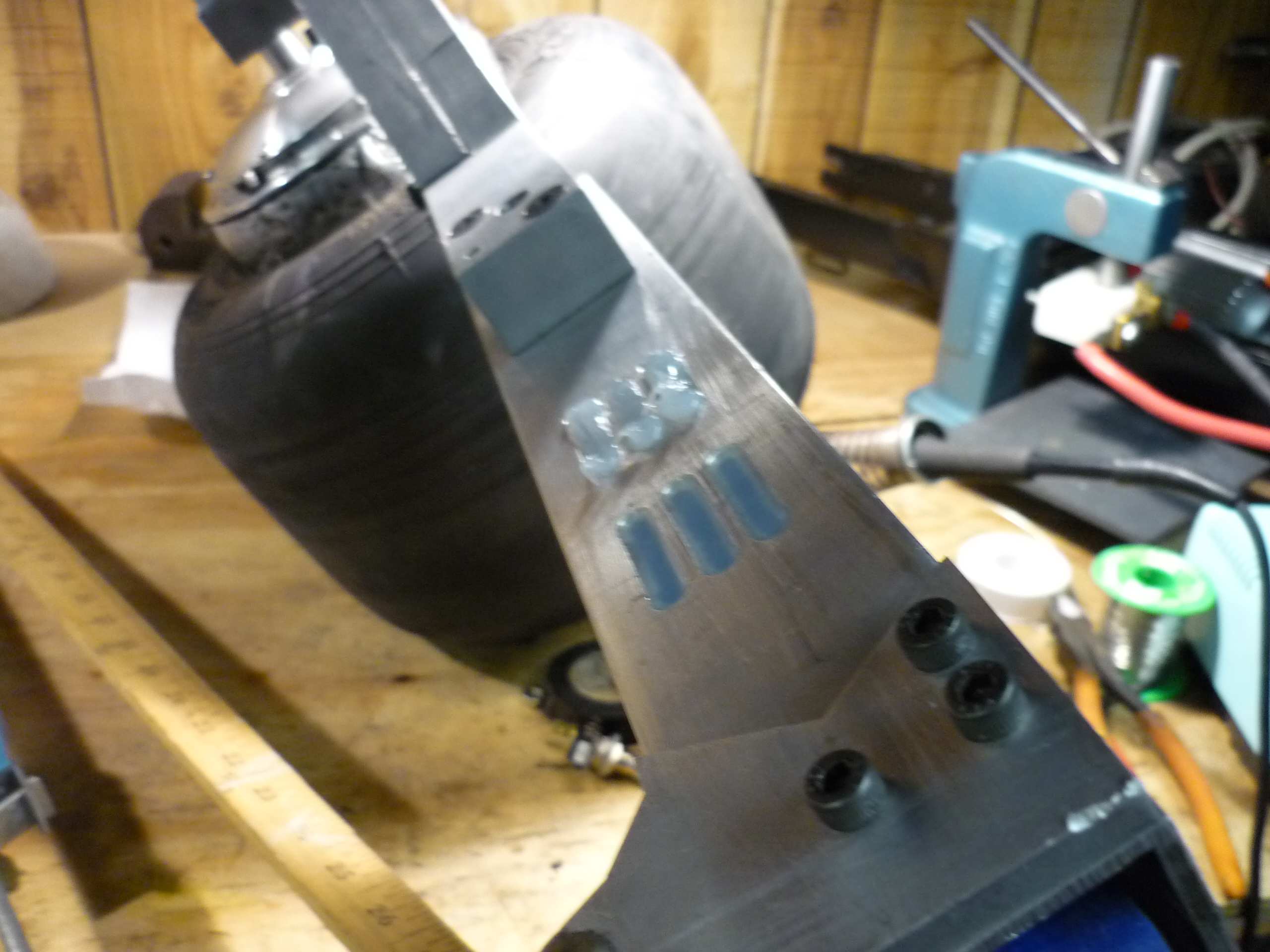
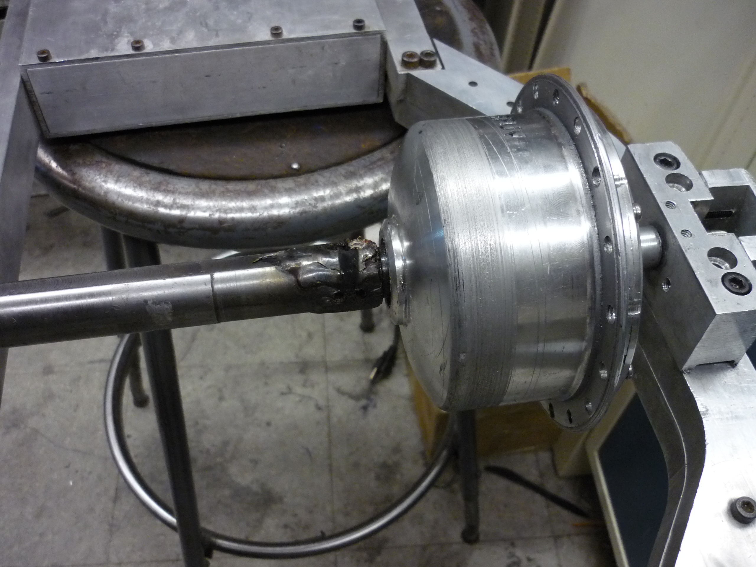
| Fighting
backlash After conversing with Adam, about backlash issues that appear over time, as the pile of set-screws wear into the hub-motor shaft, the idea of welding on the adapter came to light. After some quick milling, a flat was added to allow for a bond between the hub motor and the mating shaft. Backlash in this mate (even tenths of a degree) cause shuddering during direction change and can result in an upset rider. |
 |
 |
| DLAB
AHOY Campus was fairly empty, and fortunatley a comrade appeared so I could weld (dont weld alone!). Some quick tig-welding later (on both sides) and they appear to be one! Note the weld was performed at ~120A (high power, short duration) to prevent thermal buildup in the motor assembly. Thanks again DLAB! |
 |
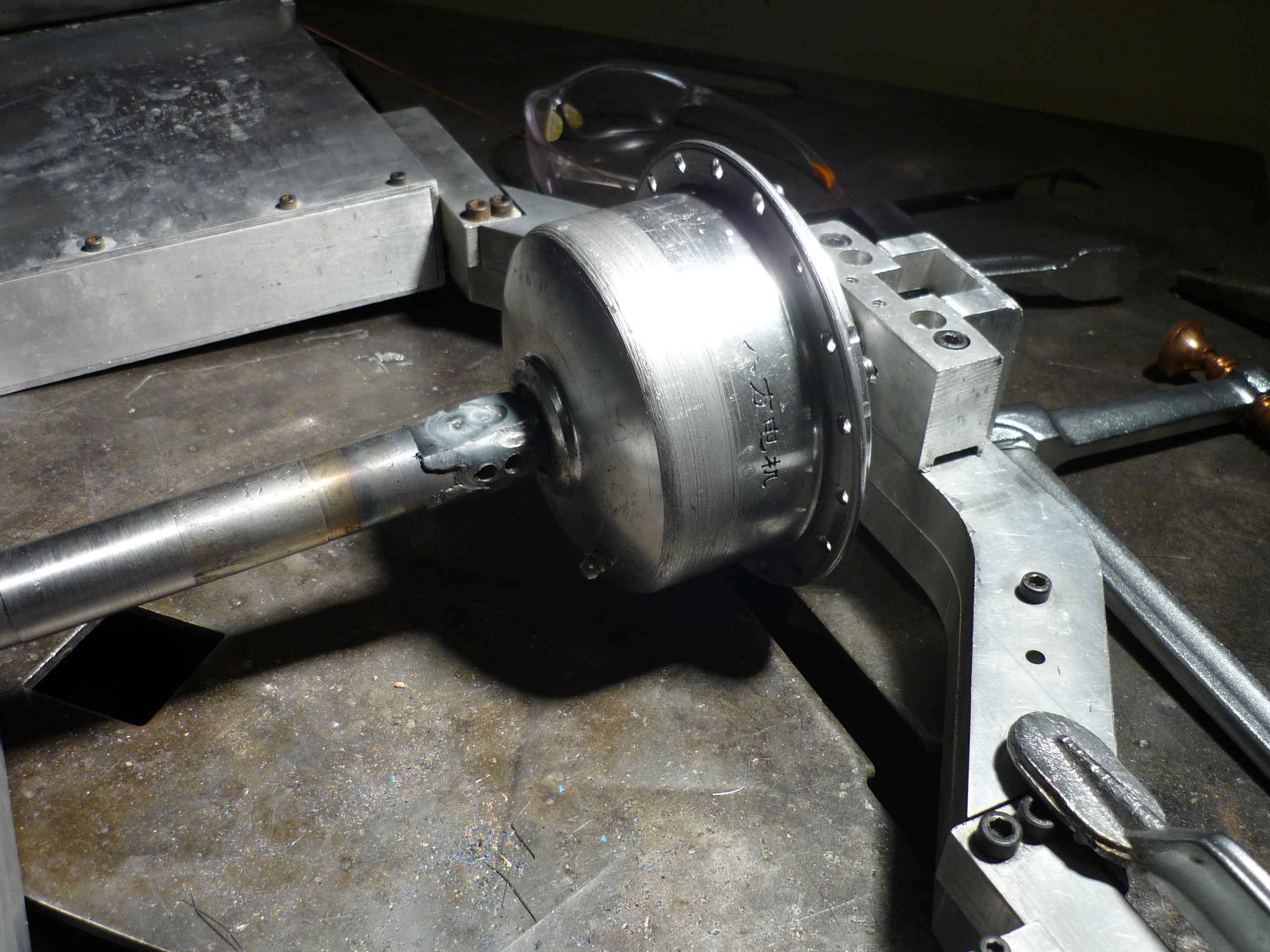 |
| PACKAGE
IT UP With the motor, adapter and everyone else re-packaged, everything fit back together! |
 |
 |
| In The Field | |
| Nimbus attempting to blend in at a holiday-get-together-shindig. | 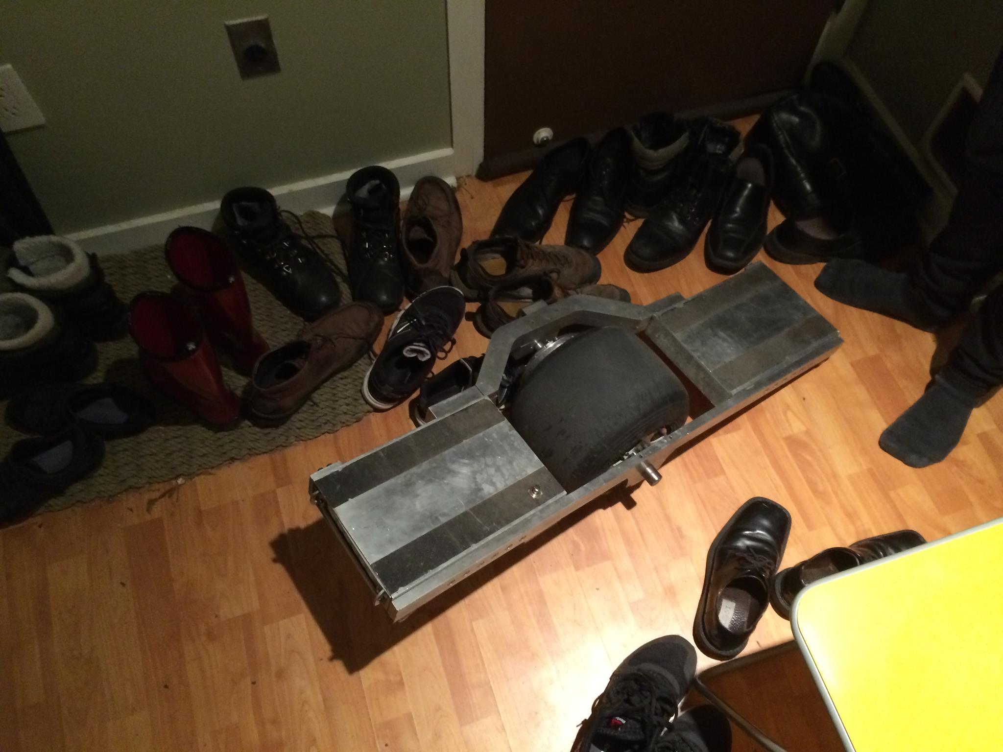 |
(There's
other photos in the photo
gallery)
Concluding
Remarks:Overall the upgrades went well, it took ~20+ miles of riding to cause the shaft-bending issue to arise. I was initially hesitant to modify the rim further, namely due to the tire seating/removal process, but thanks to some comrades, that went by better than expected. The rear LED is surprisingly powerful, and does run rather warm, I'm curious about its operating life, as it doesnt transfer heat to the frame well through the adhesive tape it's mounted with. I still need to water-seal the vent holes in the front part of the chassis in a clean fashion. Otherwise, I have received a lot of feedback on the hardware, people are really interested in riding it. Interestingly, riding it around during daytime has a binary response with nearby people, some notice right away ask questions and become incredibly overjoyed to see it, while others are in zombie mode and just see a hovering person in their periphery. Finally, ideas for upgrades are bouncing around. As of this writing the weather hasnt warranted a snow/ice tire just yet, but it does seem to loom in the distance. Riding a self balancing vehicle on a frozen lake would be fairly excellent. An improvement that has been sitting on the white board for a while was proposed by an incredibly ingenious coworker, why not replace the dead man's switch with a beam-break laser. Not only would this look fantastic (glowing green light) but it would (potentially) remove the 'failed dead mans switch' issue.
If you have questions or comments, ask below or send over an email.
| Comments: |
|
HTML Comment Box
is loading comments...
|
(be
careful, im not responsible for your incredible acceleration)
Dane.Kouttron
Rensselaer Polytechnic Institute
Electrical & Electrical Power
631.978.1650
