Dane.Kouttron
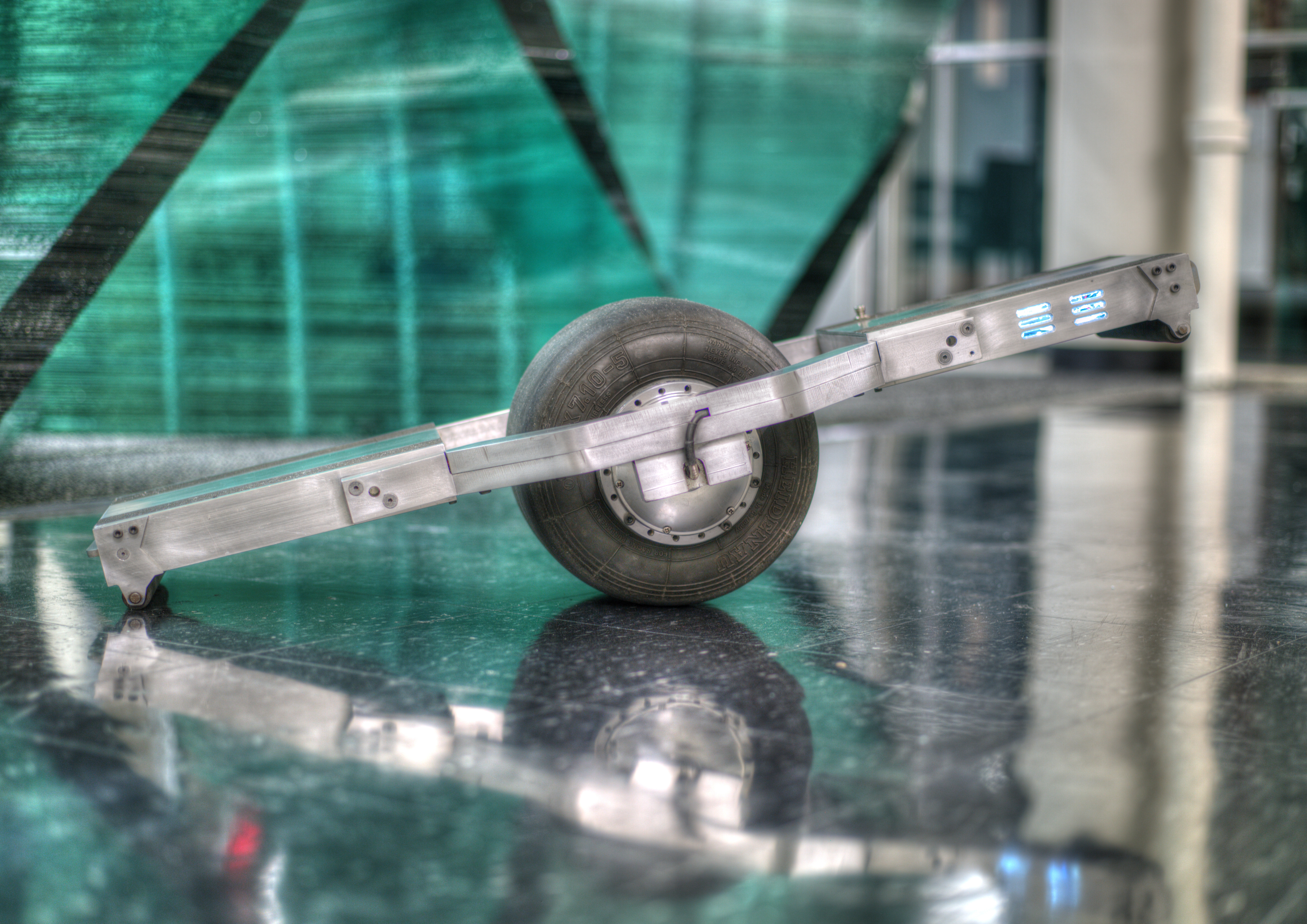
[10.29.14] The Flying Nimbus
| What?
What does a recycled (heavily used) go kart tire, an action-packed three-phase servo drive and a gyro/accelerometer have in common? A
balancing skateboard-contraption.
|
 |
 |
| What? |
Hub motor & wheel | Servo Drive | Frame | AMC To The Rescue | Control Platform | Battery | Theory | Code | Makerfaire NYC | MIT | Thanks | Hi-Res Photos | Conclusion |
| Balancing Skateboard Demo Video |
|
See below for build details, upgrades and design files! Special thanks to Advanced Motion Controls! |
| Project Background |
| This project started after finding a pile of interesting aluminum scrap, discovering a three phase dc servo drive from a recycled MIT project and dreaming of finally being able to ride a skateboard without falling all over the place. The following details the build of a balancing skateboard, the issues observed and the design files to build your own derivative. | 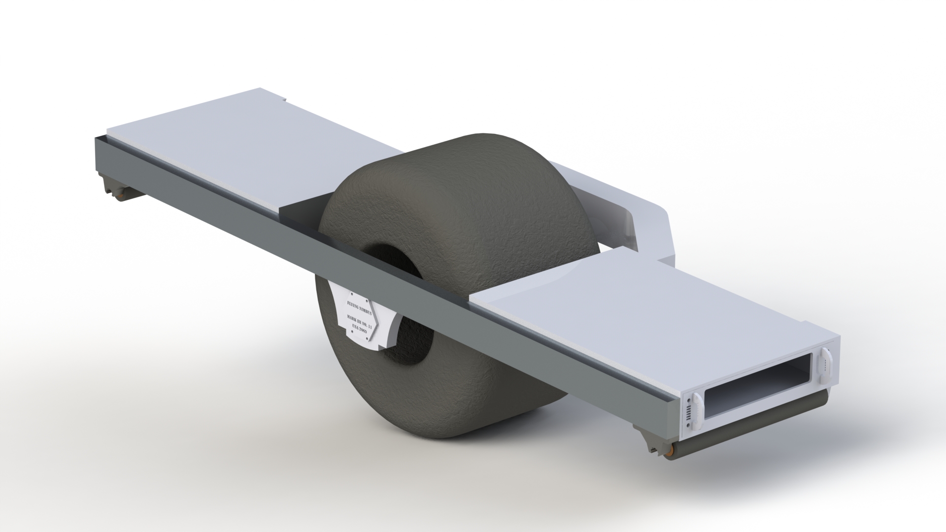 |
 |
This build log
documents the construction and iterative improvements
to create a working, balancing, single wheeled
skateboard. The design goals are namely to:
|
 |
 |
| The hub motor and a re-used wheel |
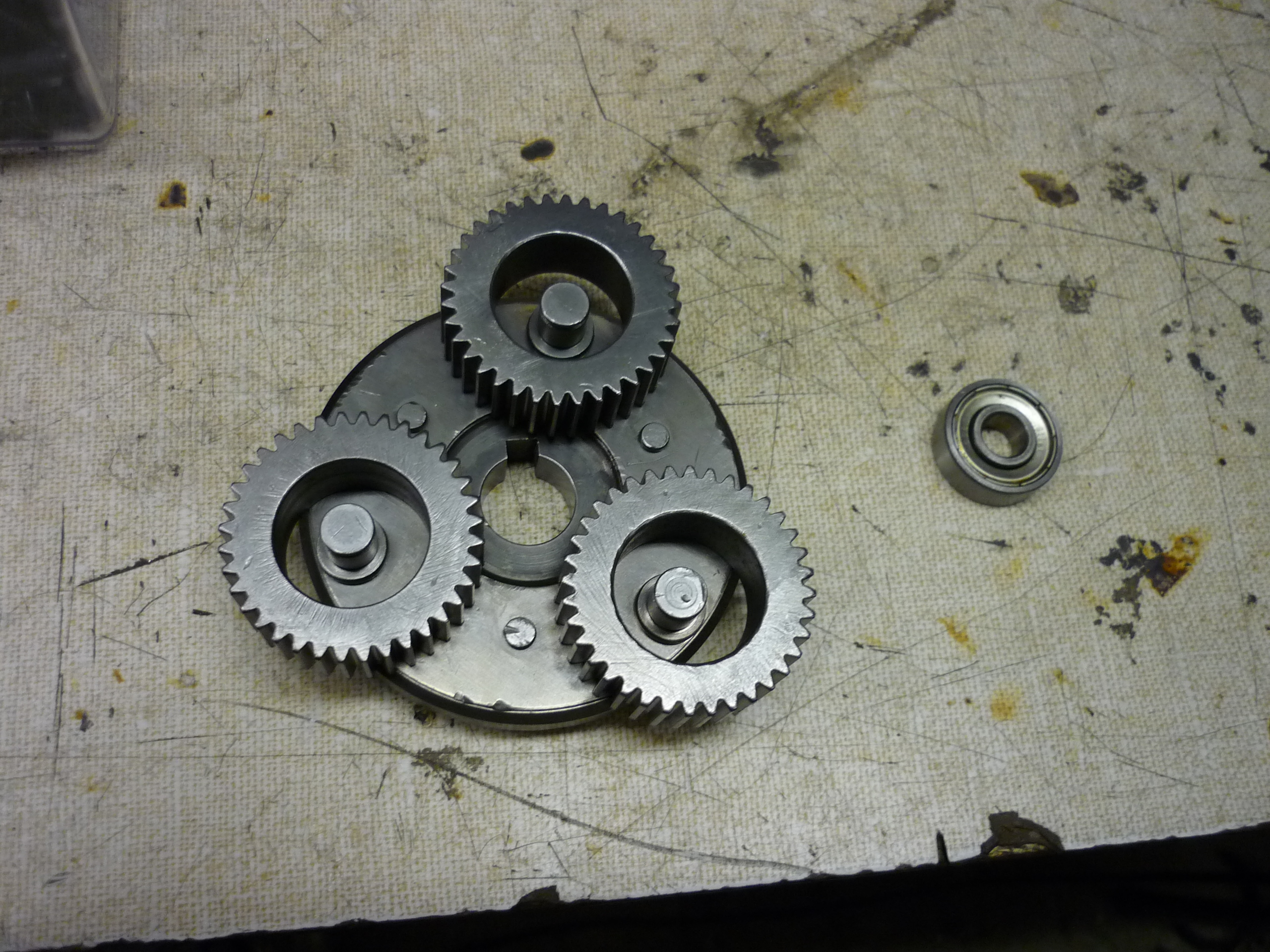
| I was given the tipoff from Jamo and Charles about a low-cost hub motor that's decently constructed. The motor is available in 24/36/48v variants, I chose the 48v as the three phase servo drive I had initially found was tailored to higher voltage lower current operation. It does take a good long while for the hub-motor show up (shipped from china) so be warned! Inside the motor lies a small planetary gear train and a three phase ~250w motor. The only limiting factor which defines the 250w rating appears to be the internal nylon planet gears inside the planetary. The nylon allows the drive to be physically quiet, but limits the maximum power transfer. | 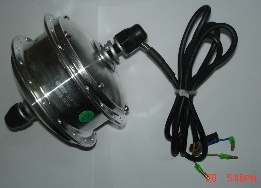 |
 |
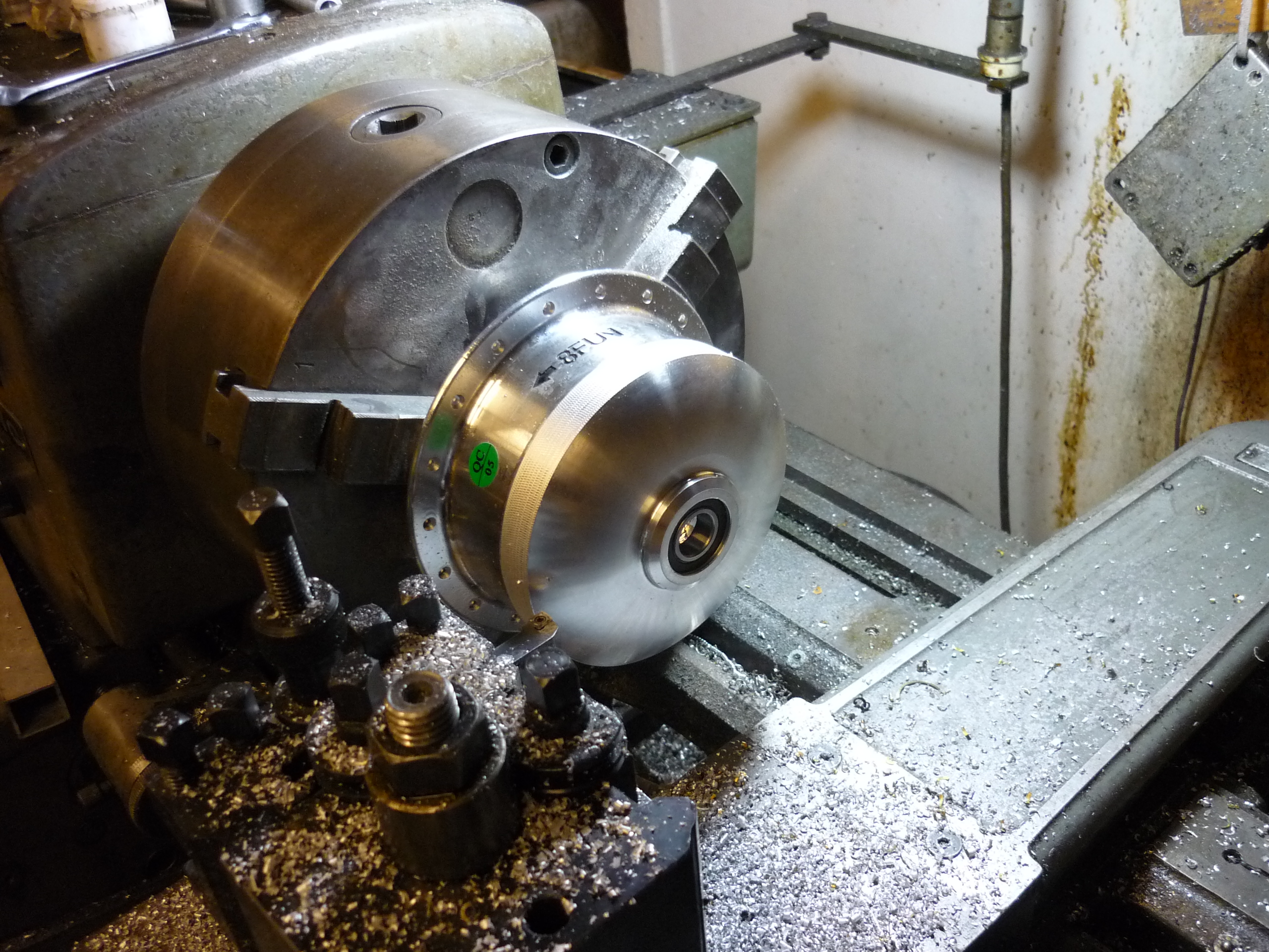
| Using the ever-powerful MITERS-MIGHTY-LATHE, I turned down one of the bicycle spoke mounts to make it flush with the case. This allows the hub motor to sit inside a 'deep' style wheel rim. I left the outer-face in place, to use it to mechanically attach the lip to the outside of the rim. As the hub-motor was made of an unknown (probably cast) aluminum, it would be disadvantageous to weld directly to it. Instead a few M4 bolts will do the load transferring directly into the motor carrier. | 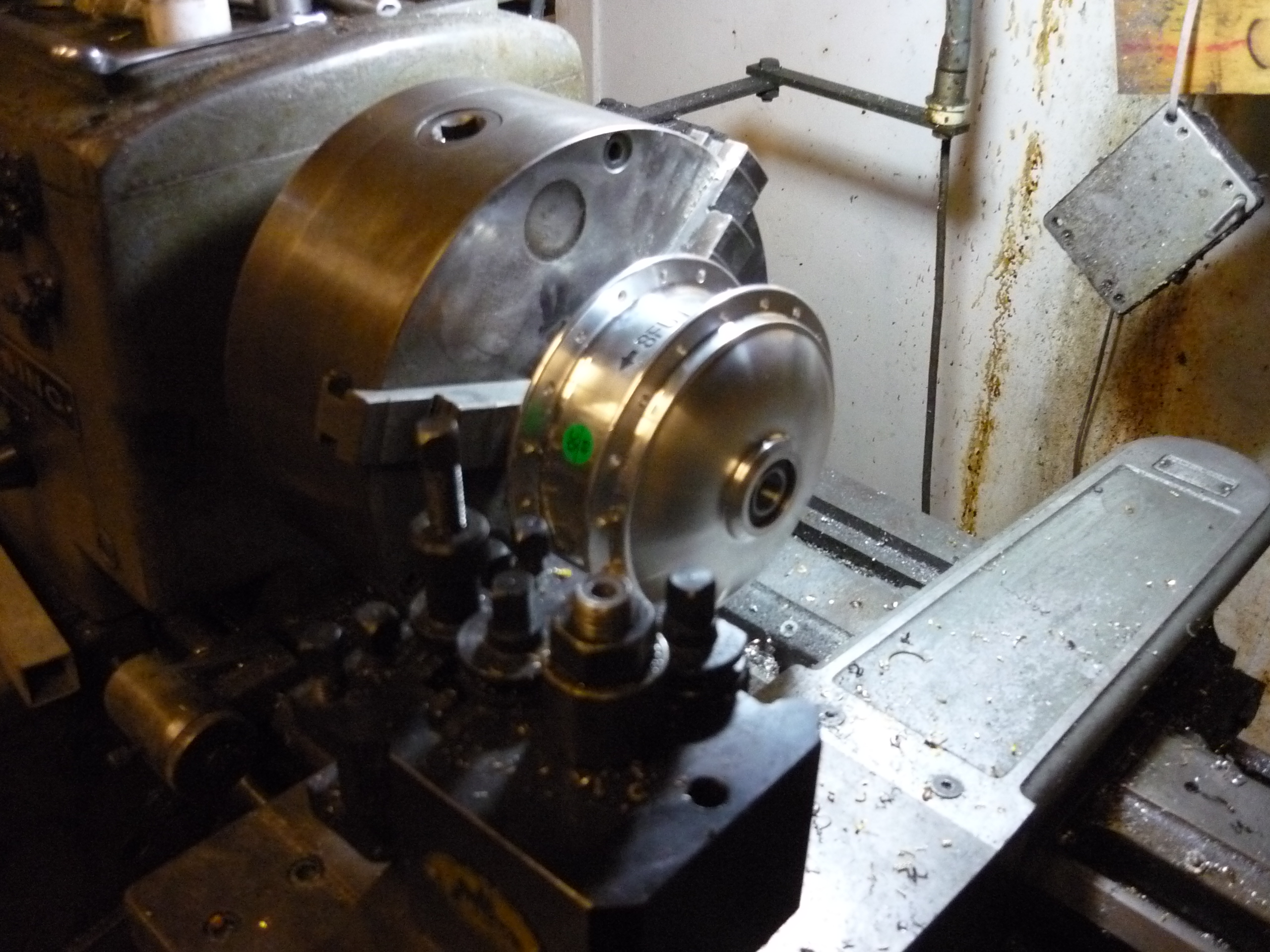 |
 |
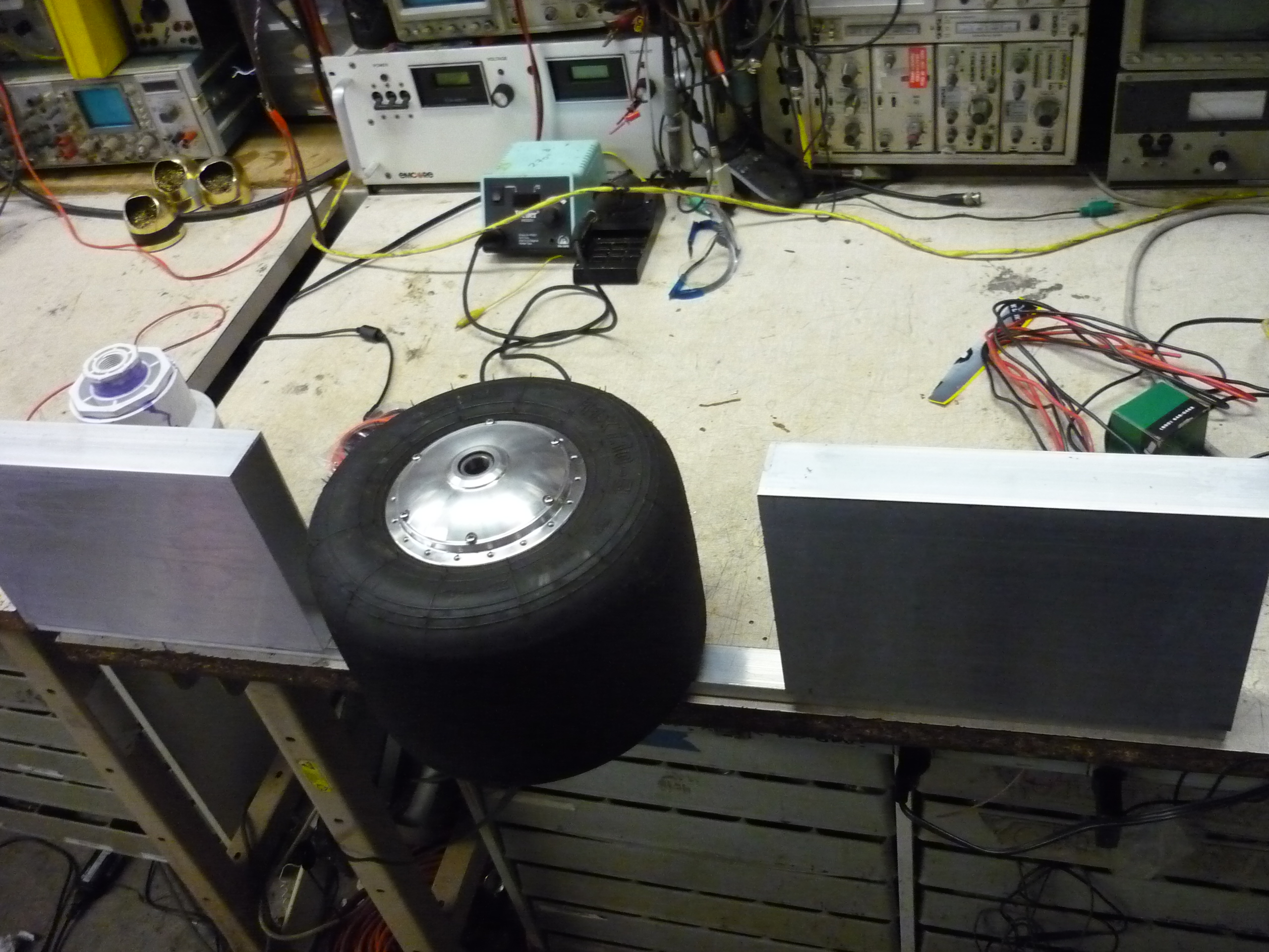
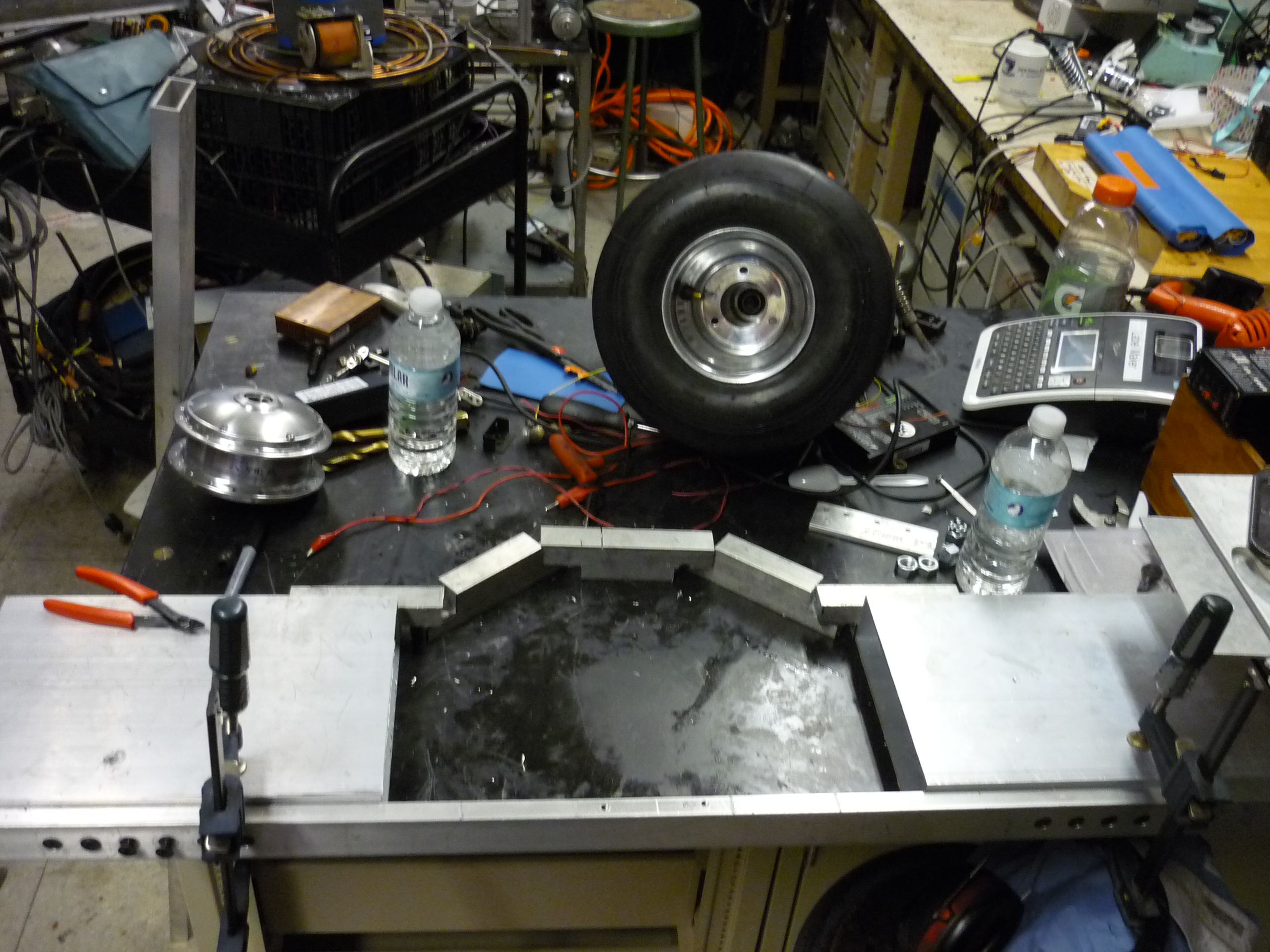
| I took a visit to F1 Boston, a fantastic place full of go karts and fun, and was fortunate to speak to a manager and grab two used go kart-tires for free. They were incredibly helpful, and the place looks like a blast to visit, with a huge track and a boatload fancy carts. A comrade had a full tire + wheel hiding in miters and I used it for early estimation of size for the motor + hub. Shown (right) is Jaguar's rim, used for sizing. |  |
 |
| The lathed-down hub slides in to the go kart tire rim (aside from the valve stem). With this, I pushed forward to getting a rim and modifying it to fit. I found an equivalent rim on ebay (slightly smaller inner diameter, and waited on it to arrive. Meantime there was plenty to do! | 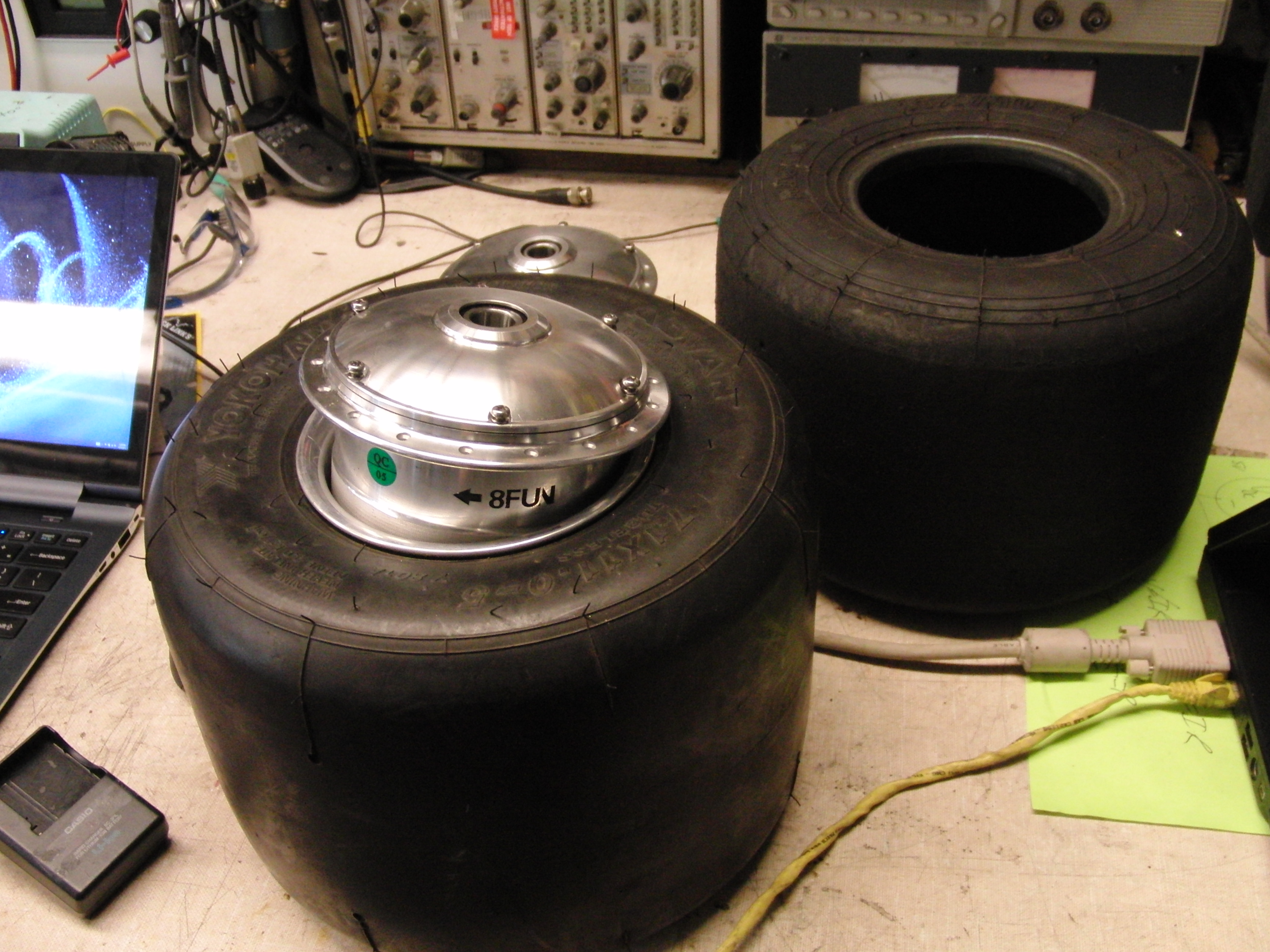 |
 |
| Design & CAD |
| I modeled the available materials (aluminum extrusion, hub motor, go-kart wheel) as well as the planned components. This allowed for 'plugging in' designed components to verify that they would fit / work, instead of making them and finding out later on that they were too small / big. Admittedly, batteries and weld straps suffered the 'make room for weld straps' issue. Having a rough modeled design also allowed for water jet parts to be designed and dropped in, without having to worry too much about fit / placement. |
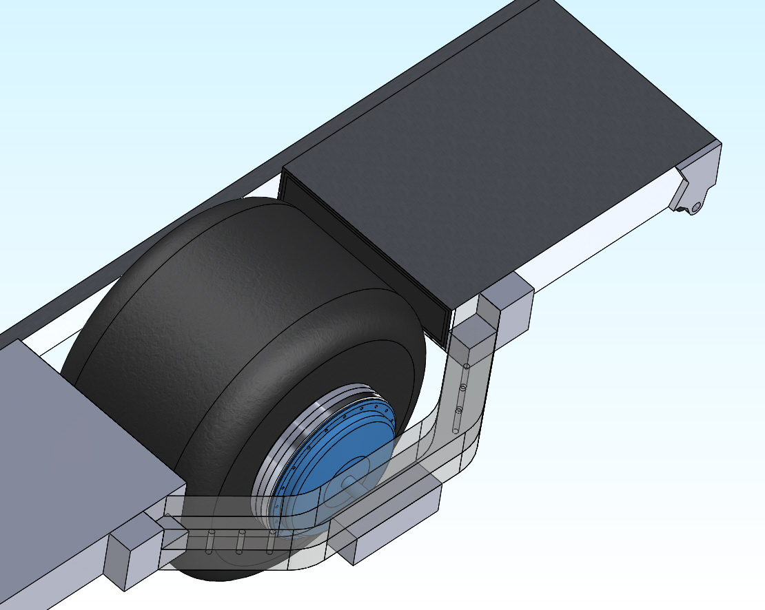
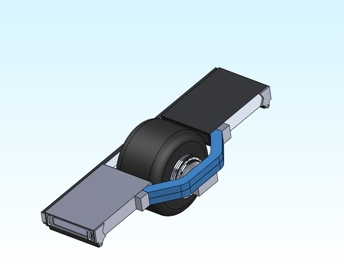
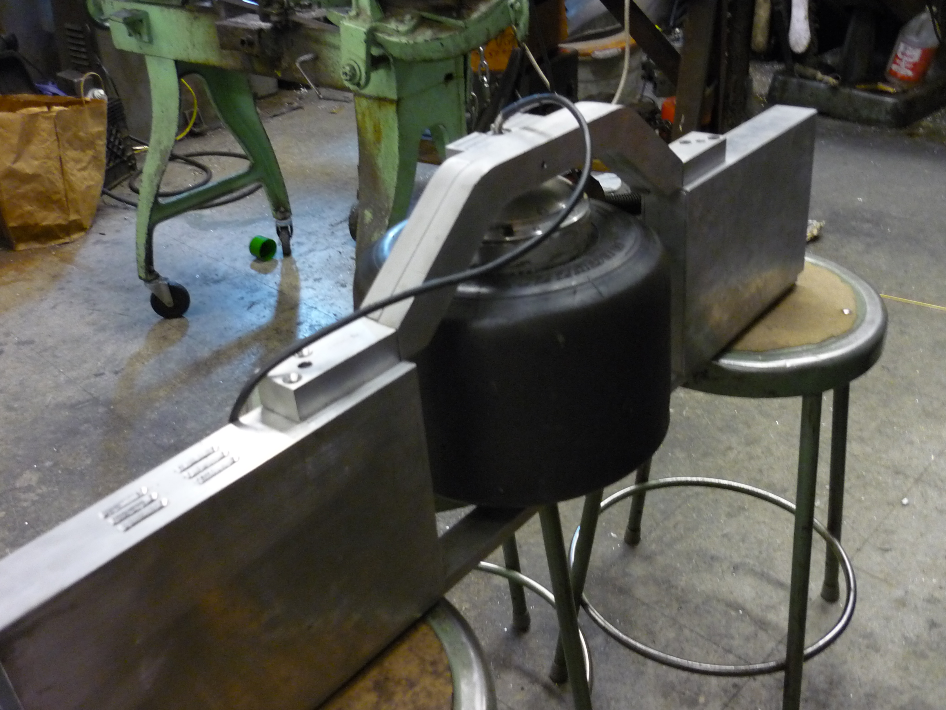
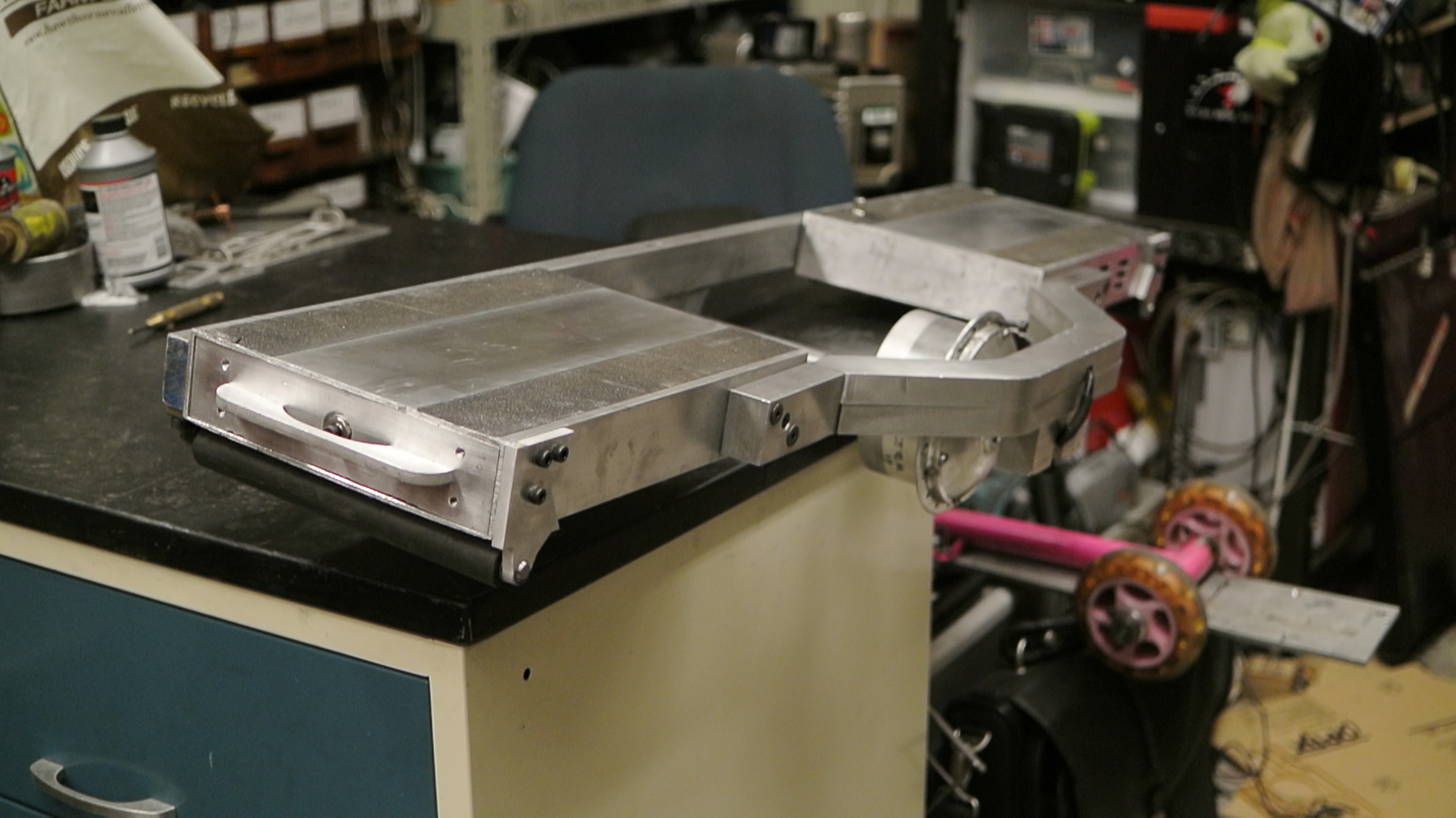
| '8-FUN' hub motor The hub motor proved to be the least-fun part to model, as it's accuracy was necessary for everything that touched it to mate successfully. Shown (right) is the hub motor embedded in the ring-support structure, hidden behind the swing-arm, detailed below. The swing-arm assembly is made from some heartily scavenged aluminum scrap, 0.75" thick. Using a Bridgeport (detailed below) a channel for cabling was made, inside the structure, to integrate cable management and front-rear mechanical stability. |
 |
 |
| Slide-out battery + power trays The volume available for the battery is unfortunately limited, having no idea what the efficiency (watt-hours / mile) of a balancing skateboard was, I opted to make the battery packs removable, so, a backup battery could be hauled around and latched in place. After designing the battery tray, I continued the trend with the motor controller + accelerometer / gyro side of the contraption. |
 |
 |
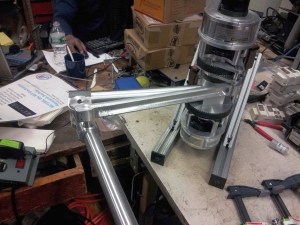
| A three-phase servo drive, some tear down and pin out reverse engineering |
| The motor
controller I had initially planned to use for this
craft was a small form factor advanced motor controls
drive. I had luckily found this from a recently
completed & scrapped research project @ MIT and
managed to remove it from the chassis it was installed
in. The form-factor was perfect for the
skateboard frame, although the maximum current was
quite a bit lower than I would end up needing. [Data sheet] [Website link] |
 |
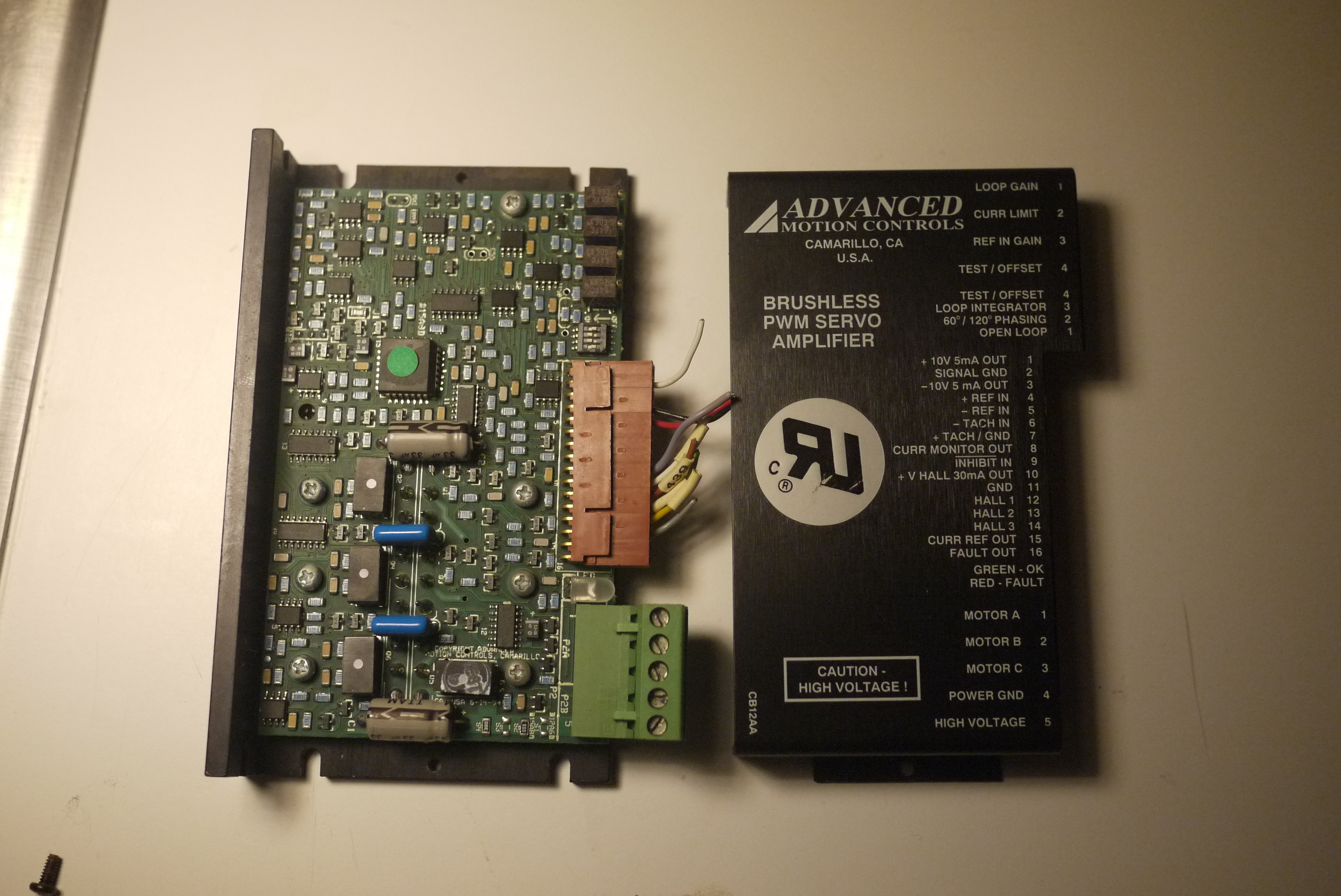 |
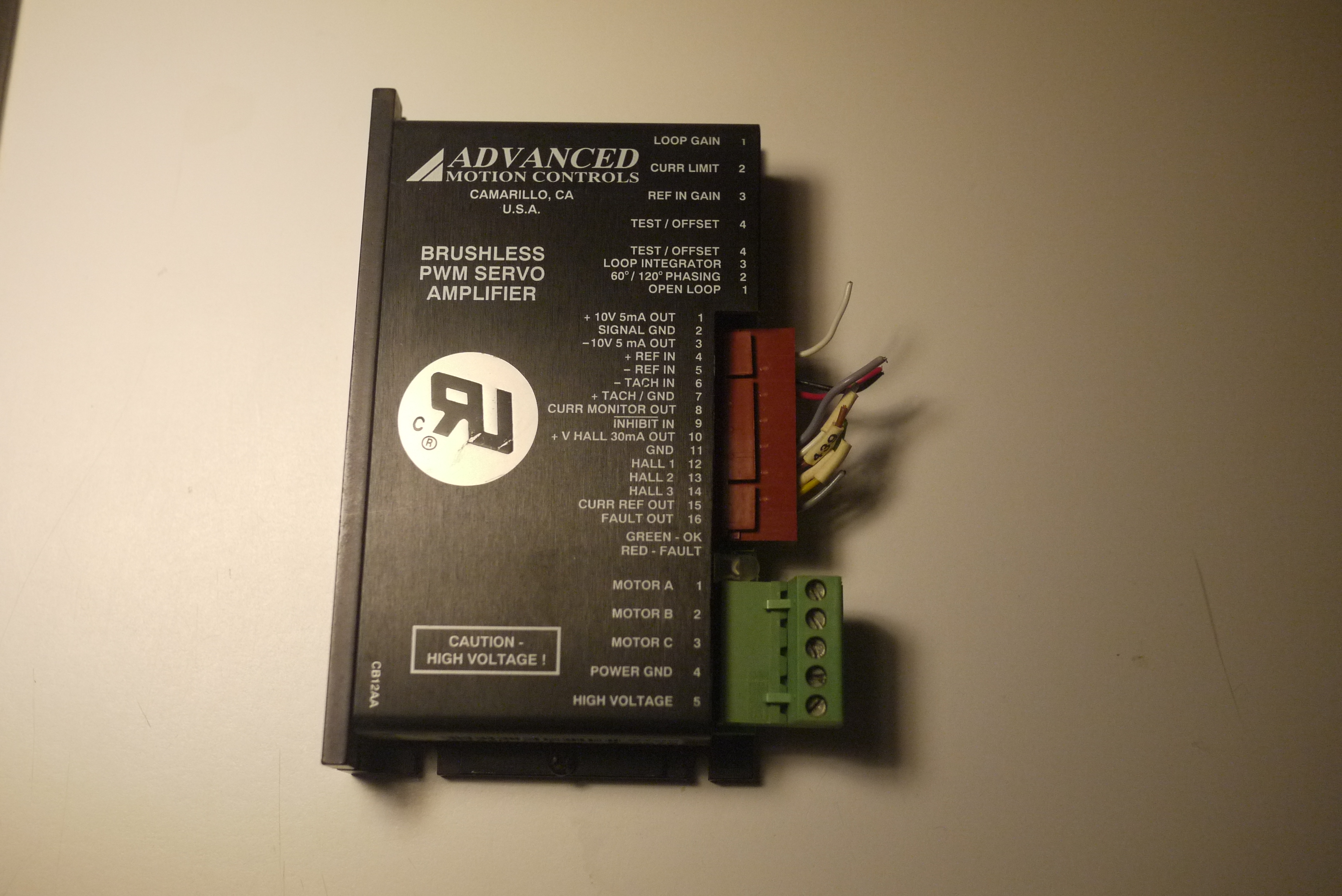
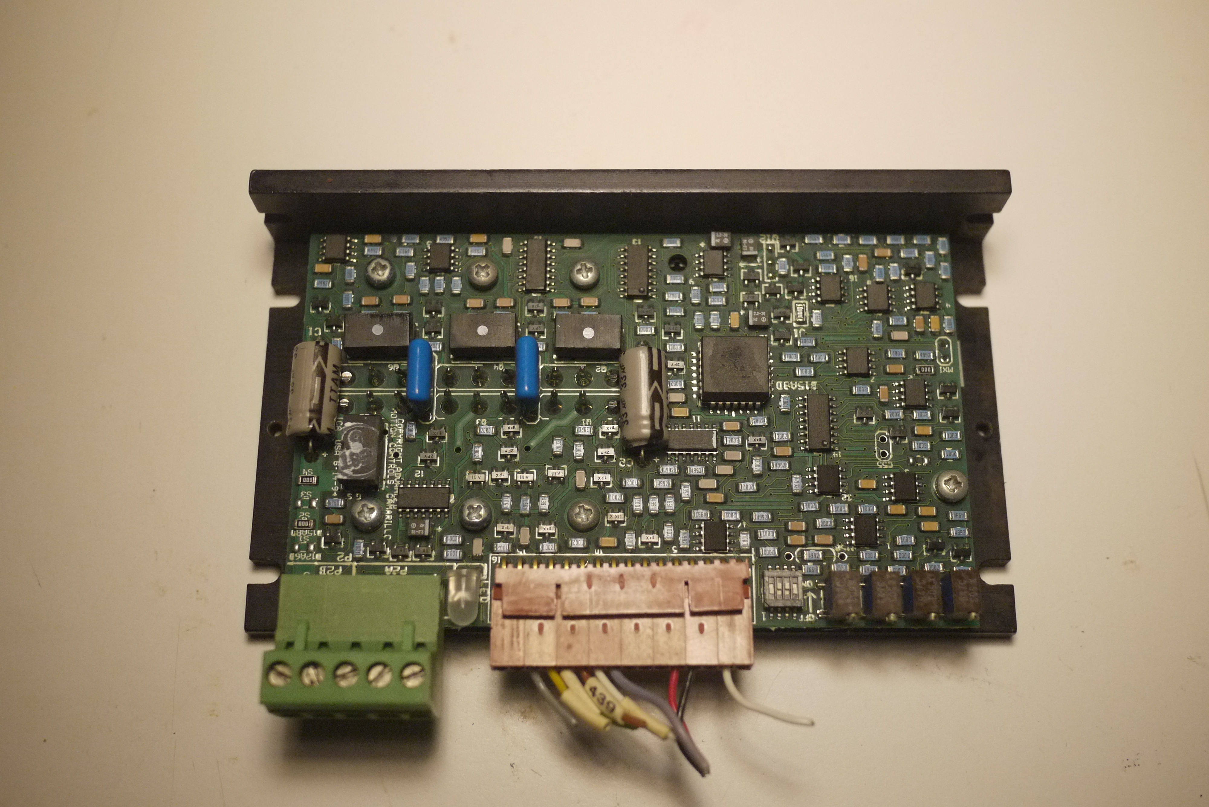
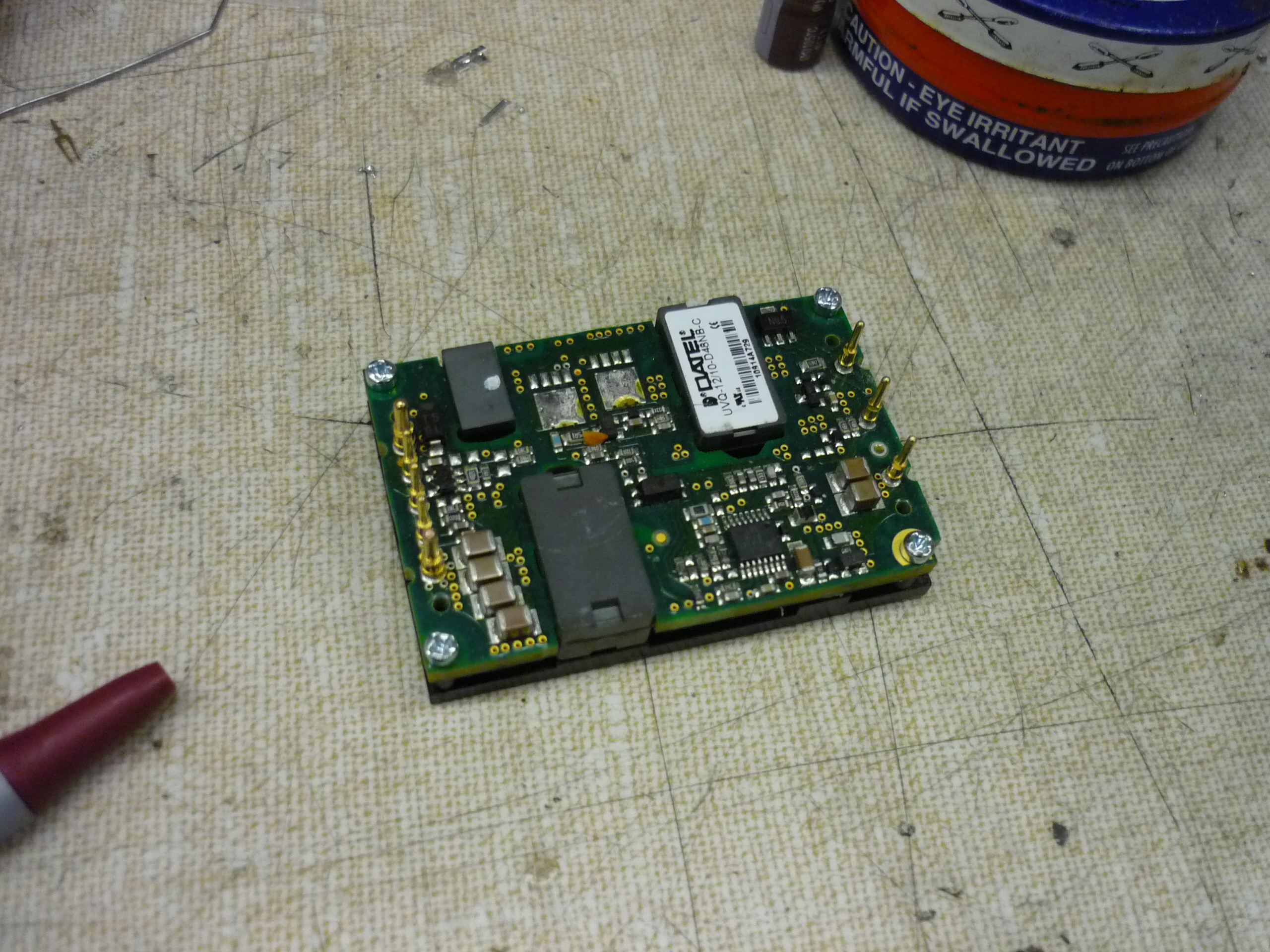
| Internal photo of servo drive. Being curious, I opened the drive to checkout its innards. Everything is neat and orderly, with the switching elements (TO-247 mosfets) adhered to the frame below. I like the design, TO-247's are a great package, they get awesome thermal contact with the casing. I was unable to get directly at the mosfets used in the design, but it appeared that the controller could probably handle significantly more than its rated current. |
 |
 |
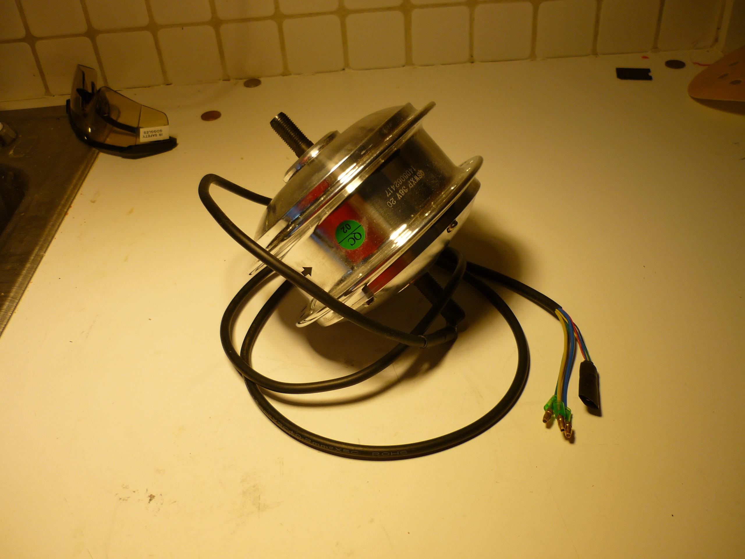
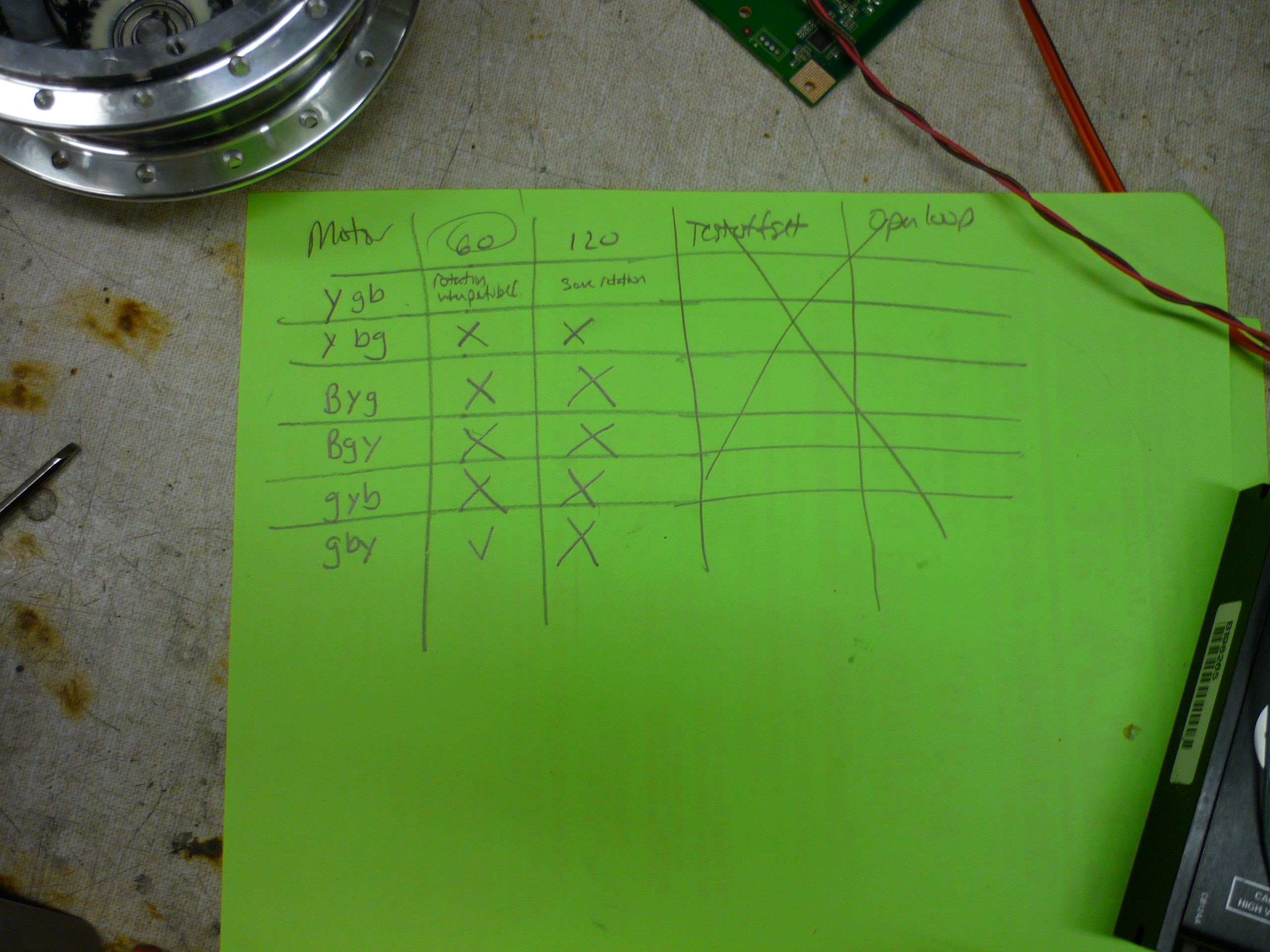
| Reverse engineering the brushless motor's pin
out Unfortunately the motor's sensor wiring was not documented, so some reverse-engineering was required. For those of you out-there looking to wire-up a Baeofun '8-fun' motor; the motor hall effect sensors are positioned 120 degrees apart, Sensor 1 is Green Sensor 2 is blue and Sensor 3 is Yellow. Power and ground for the sensor board are red and black, respectively. |
 |
 |
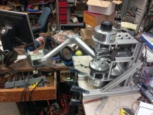
| A slightly bigger servo drive. Jamo, of the variable constant, gifted me a slightly higher power servo amplifier drive, scrapped from a media lab project. It was a very tight fit to get this into the frame. It also appeared to run significantly hotter than the A-M-C drive, but, given its listed current rating, I opted to use it for the propulsion drive testing. More info on this drive is available below. |
 |
 |
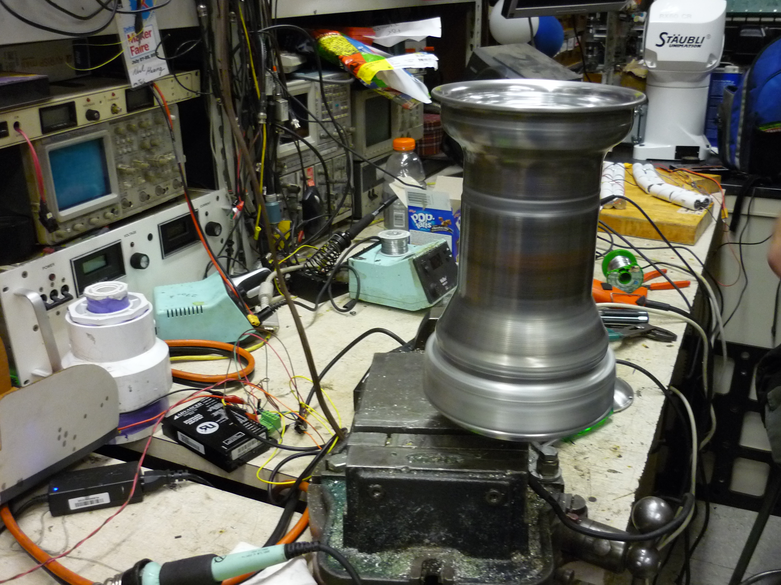
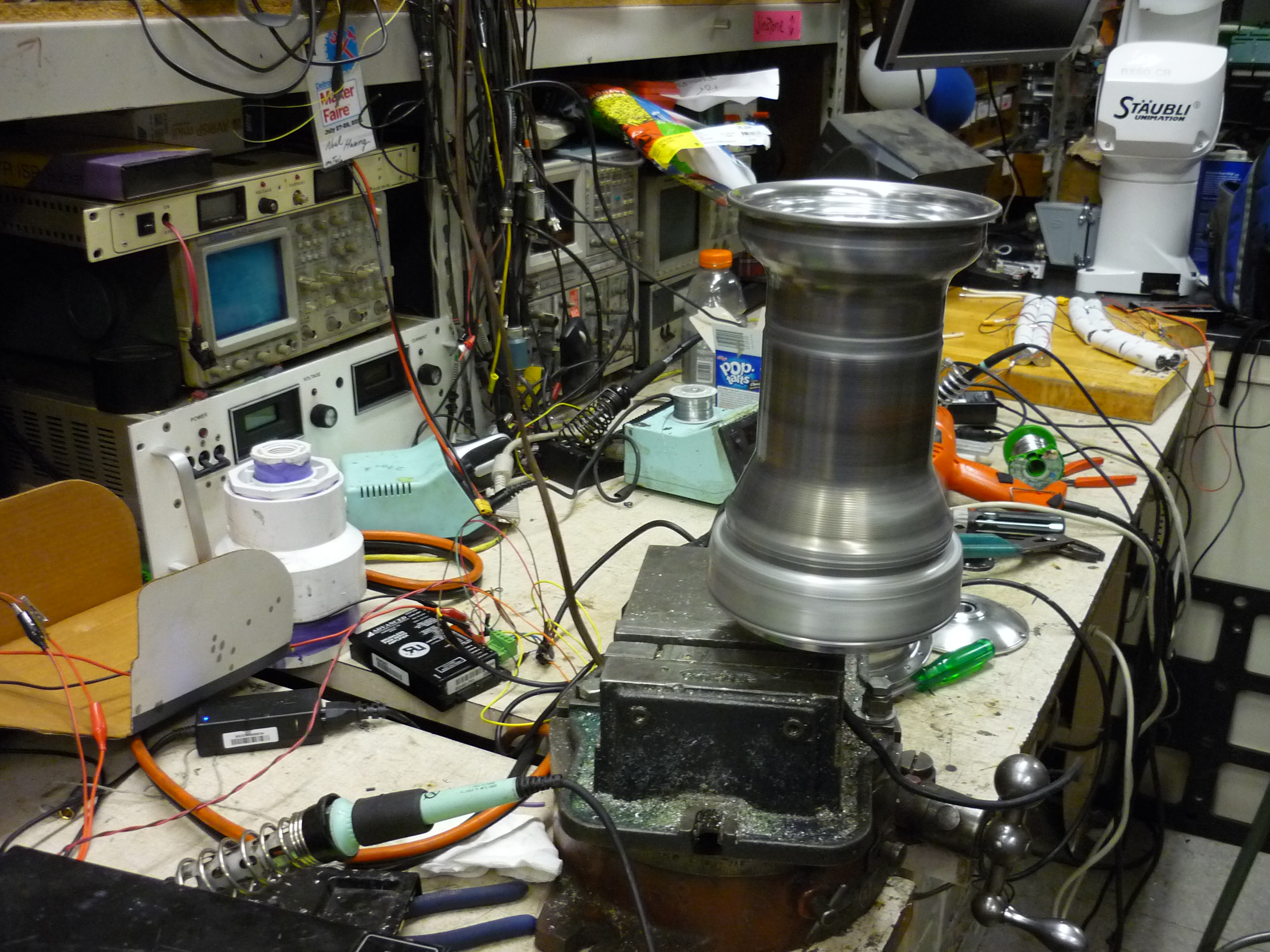
| First motor spool up | |
|
|
| Making the rim extender and mounting the hub-motor to the rim. |
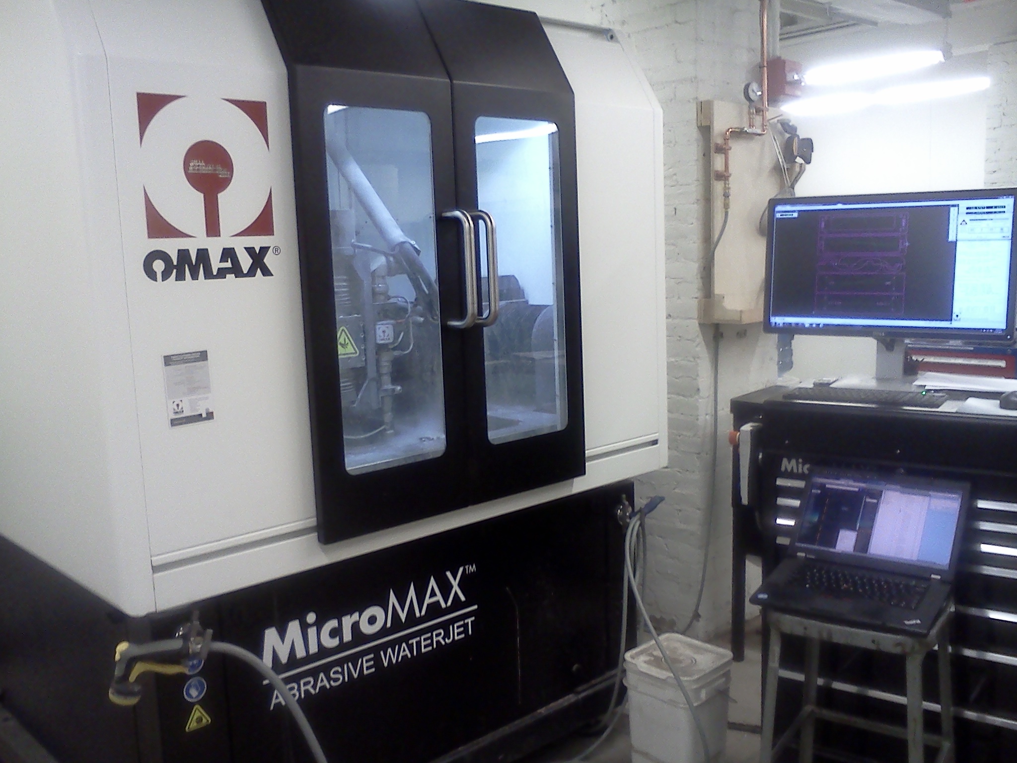
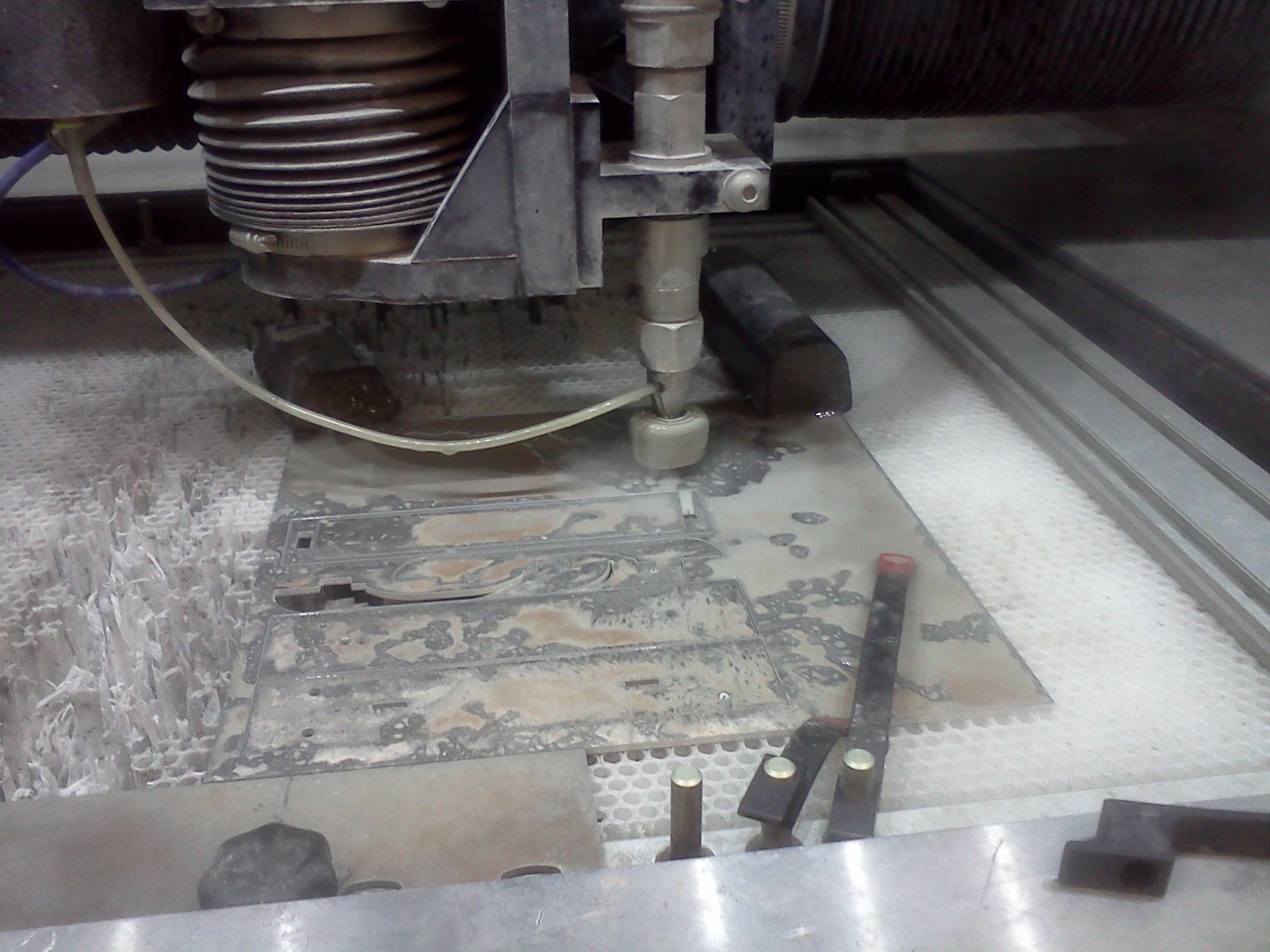
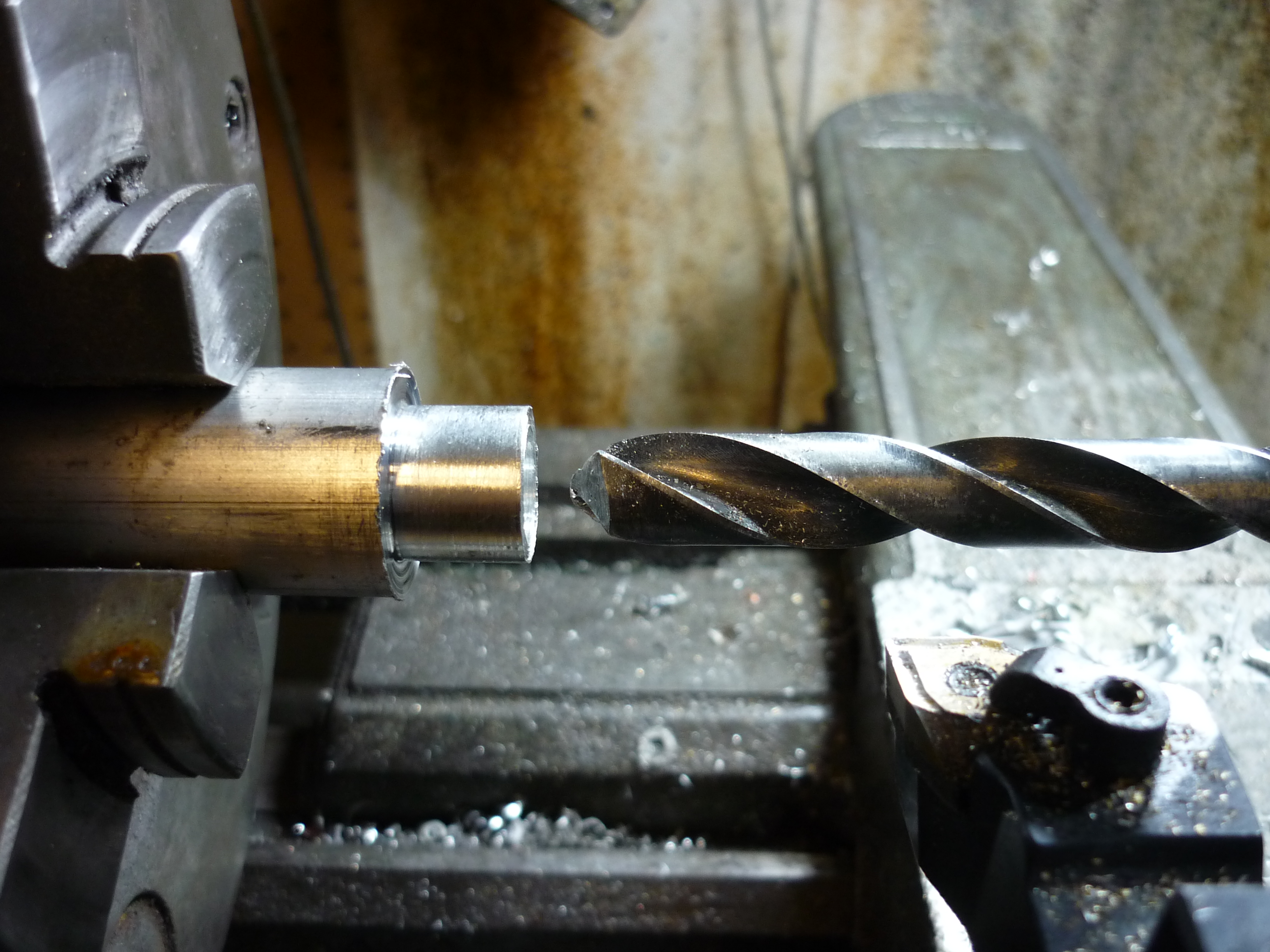
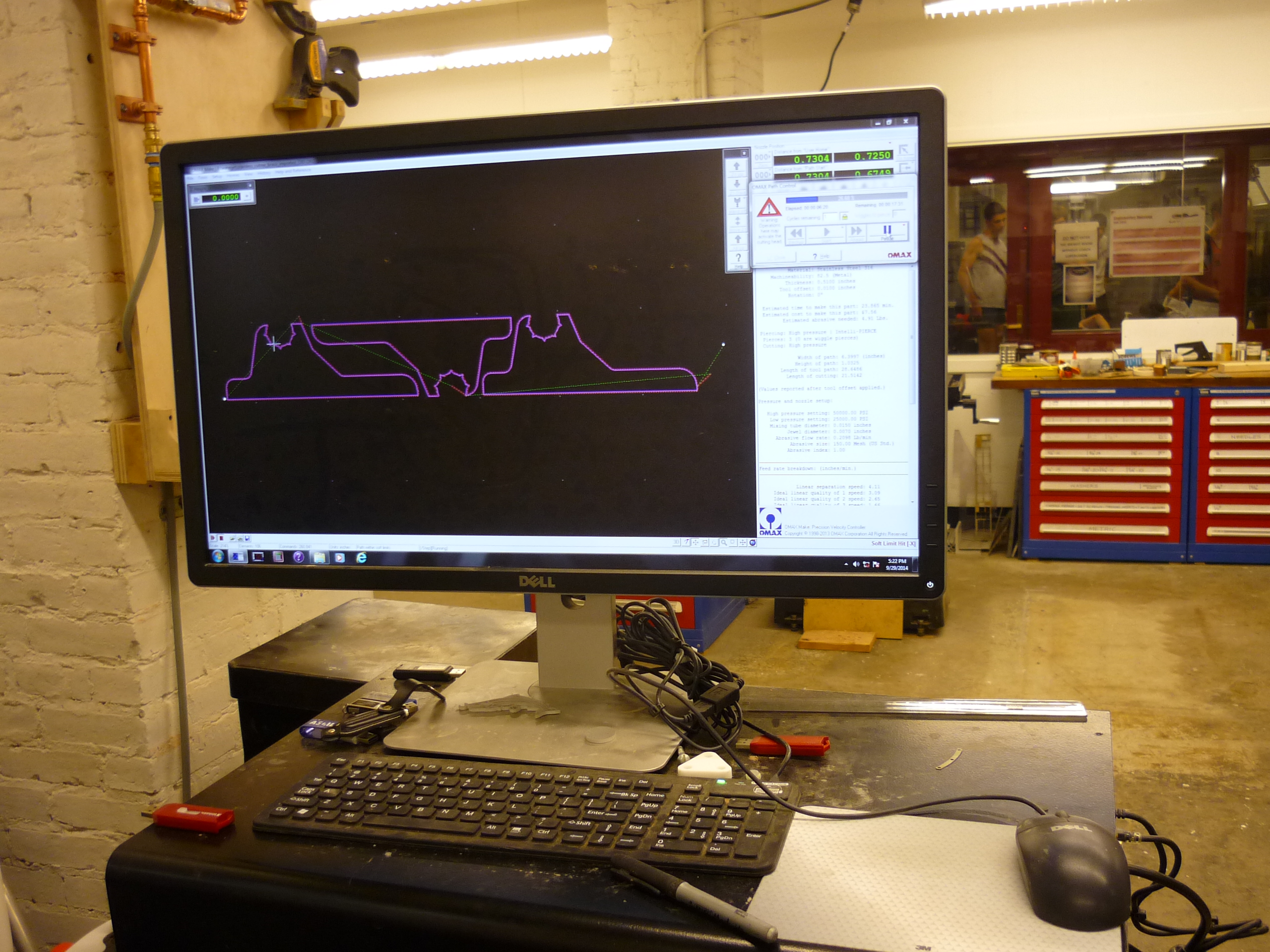
| The 6061 aluminum rim from ebay was too shallow to fit the hub motor directly into. Ideally I would have grabbed a nearly similar sized aluminum tube and ream / turn it down to fit, however, it was too odd of a size and I wanted to finish the craft for a trip to New Hampshire. The closest thing available was a 0.25" thick 1' square sheet of aluminum, intended for the atomic bumble battle bot. I was able to use the MIT hobby shop's brand-new super-accurate OMAX micro-jet to cut the risers. Note one ring is purposely smaller than the remaining rings to allow space around the tire. | 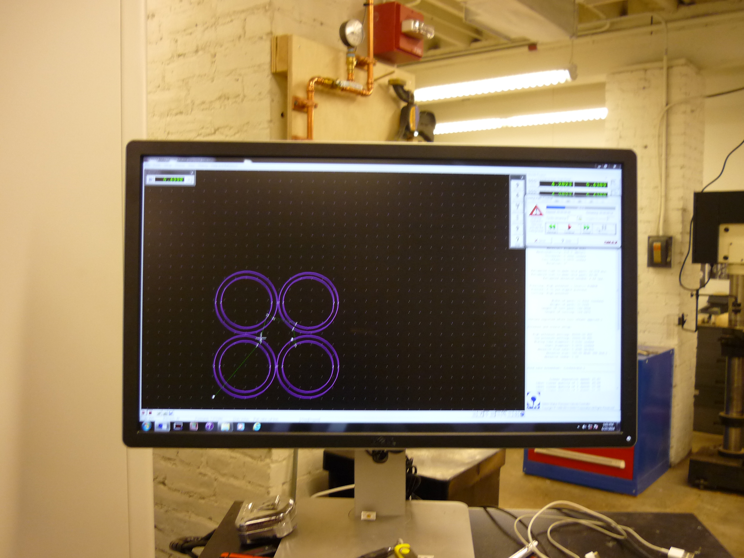 |
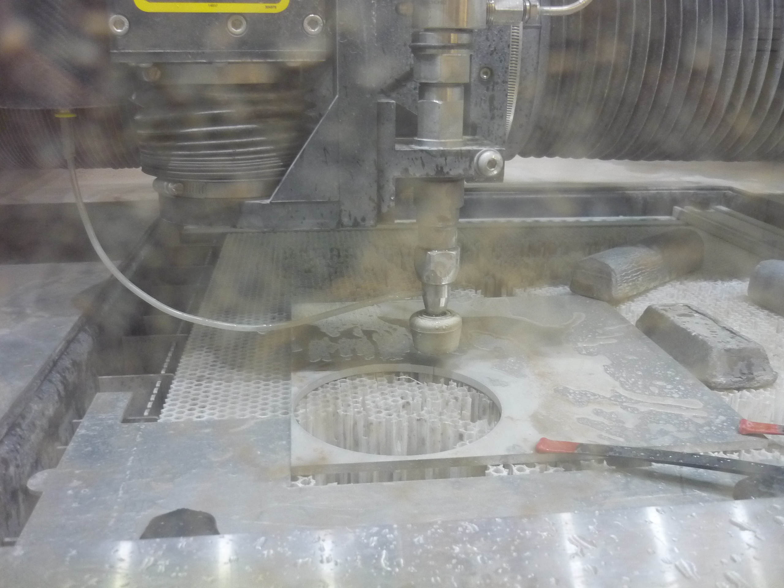 |
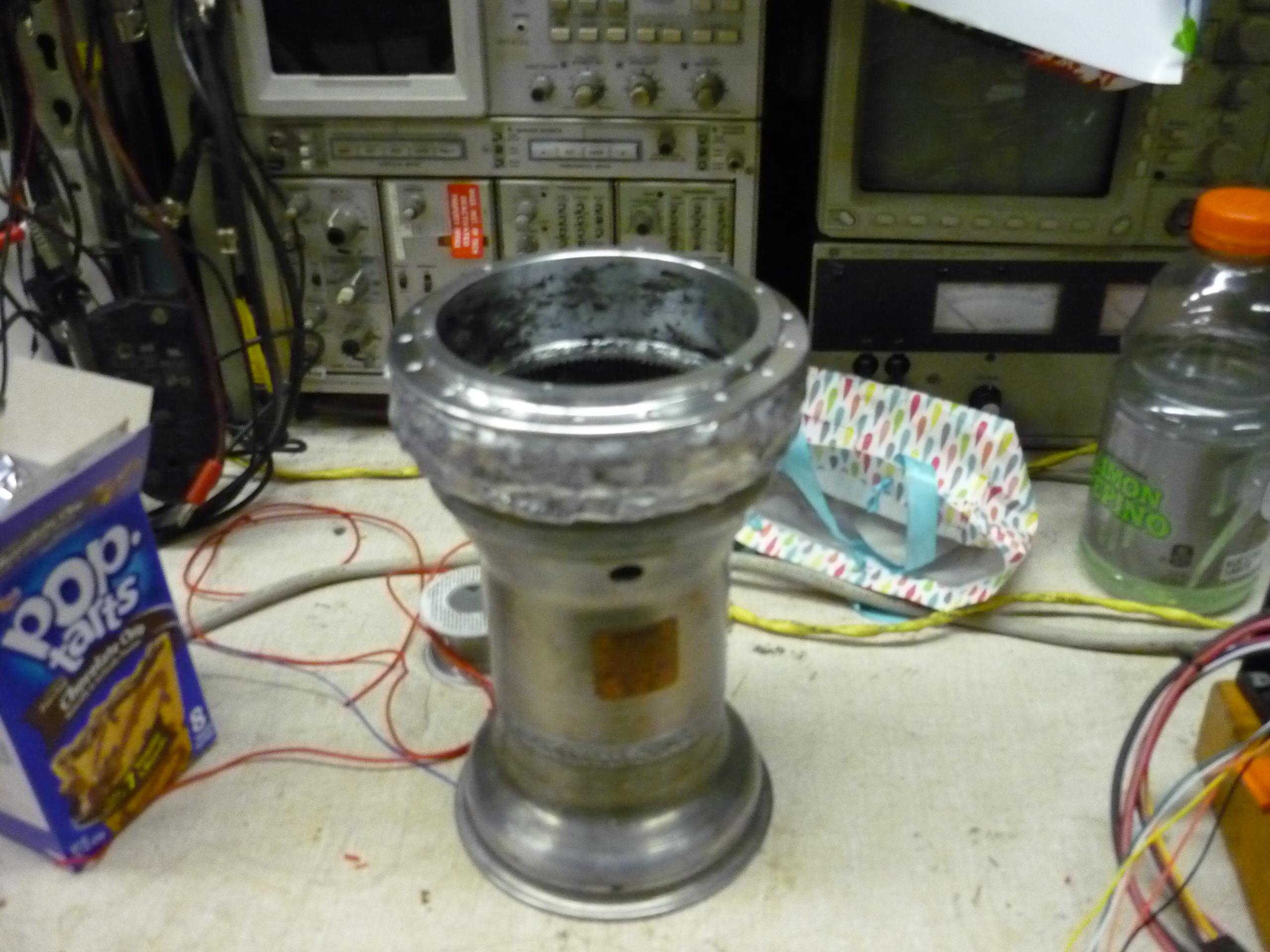
| With the newly cut 6061 aluminum rings, I fit test the first ring, which was intended to align directly with the outside of the hub. It fit like a glove. By aligning the bottom ring with the outside of the rim, the inside of the ring was used to align all the subsequent rings. At this stage i pulled out the existing valve stem, as shown by the gaping 15/32" hole. Later on this hole was plugged with an aluminum wedge and welded in place. This turned out later on to be surprisingly airtight! | 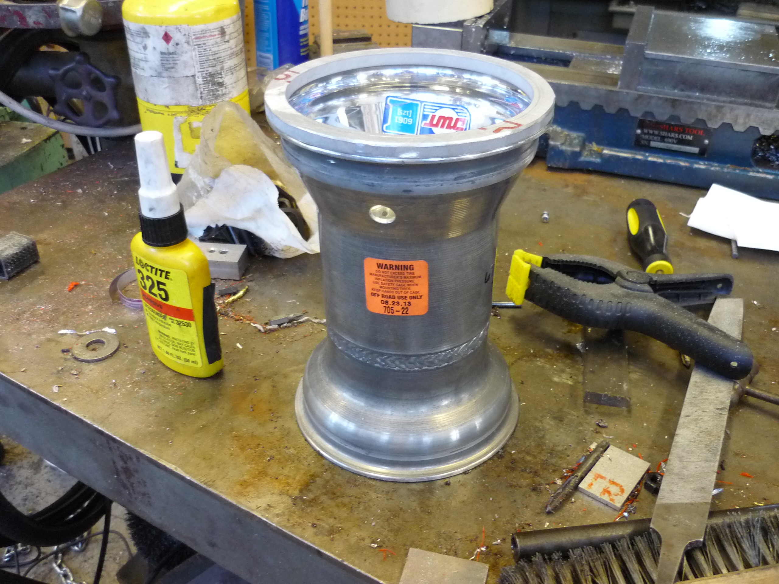 |
 |
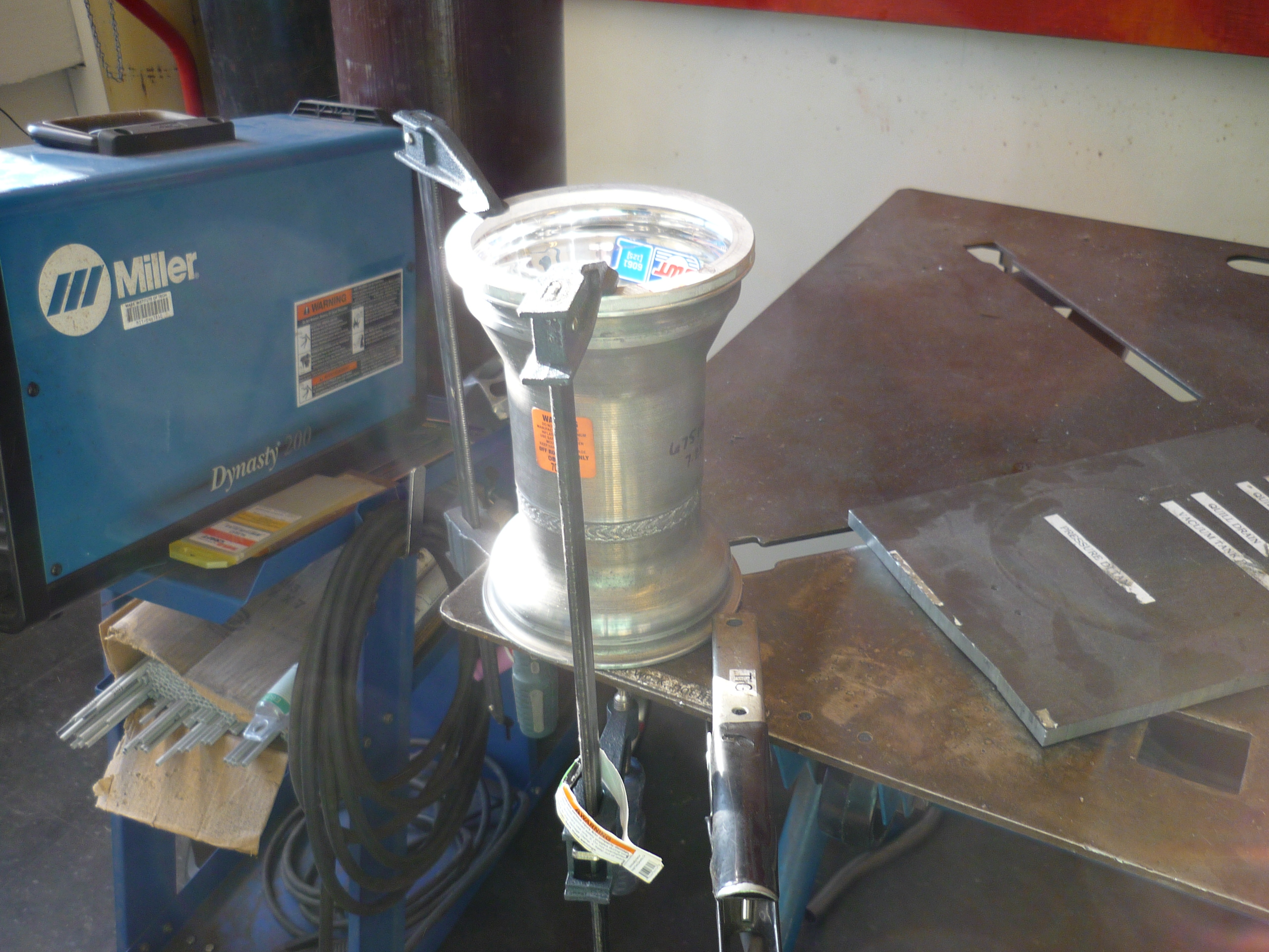
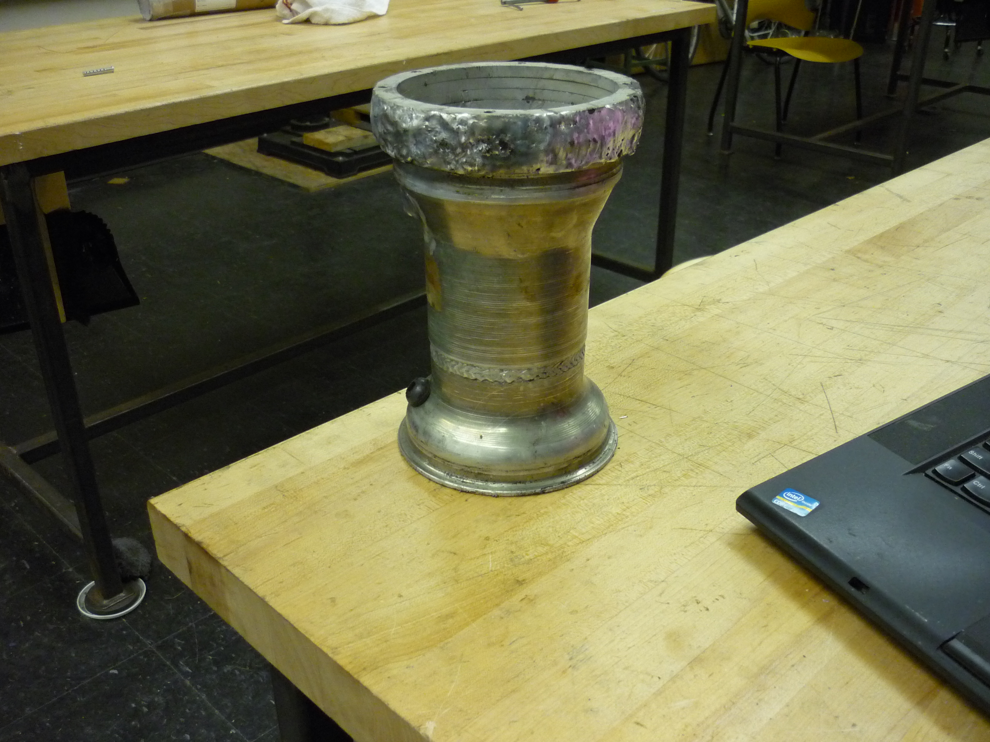
| Some tig-welding later There is a lot of thermal mass between the rim and the riser rings, as such welding was a fairly long process. After about an hour of pre-heating and tig welding, the rim was a globby aluminum extrusion, ready to be turned down and have a hub-motor inserted. Note, this was my second go at TIG welding, and aluminum is a tricky material to weld well. |
 |
 |
| Gorilla bubblegum As I mentioned, there was a lot of thermal mass, and a lot of filler rod added to the setup, but everything ended up fitting together well. shown right is the hub motor innards fitting inside the welded rim-extender, with the outside lip resting on the edge of the rim-extender. This whole rig took about 30 minutes to cool down before moving it from the welding table! |
 |
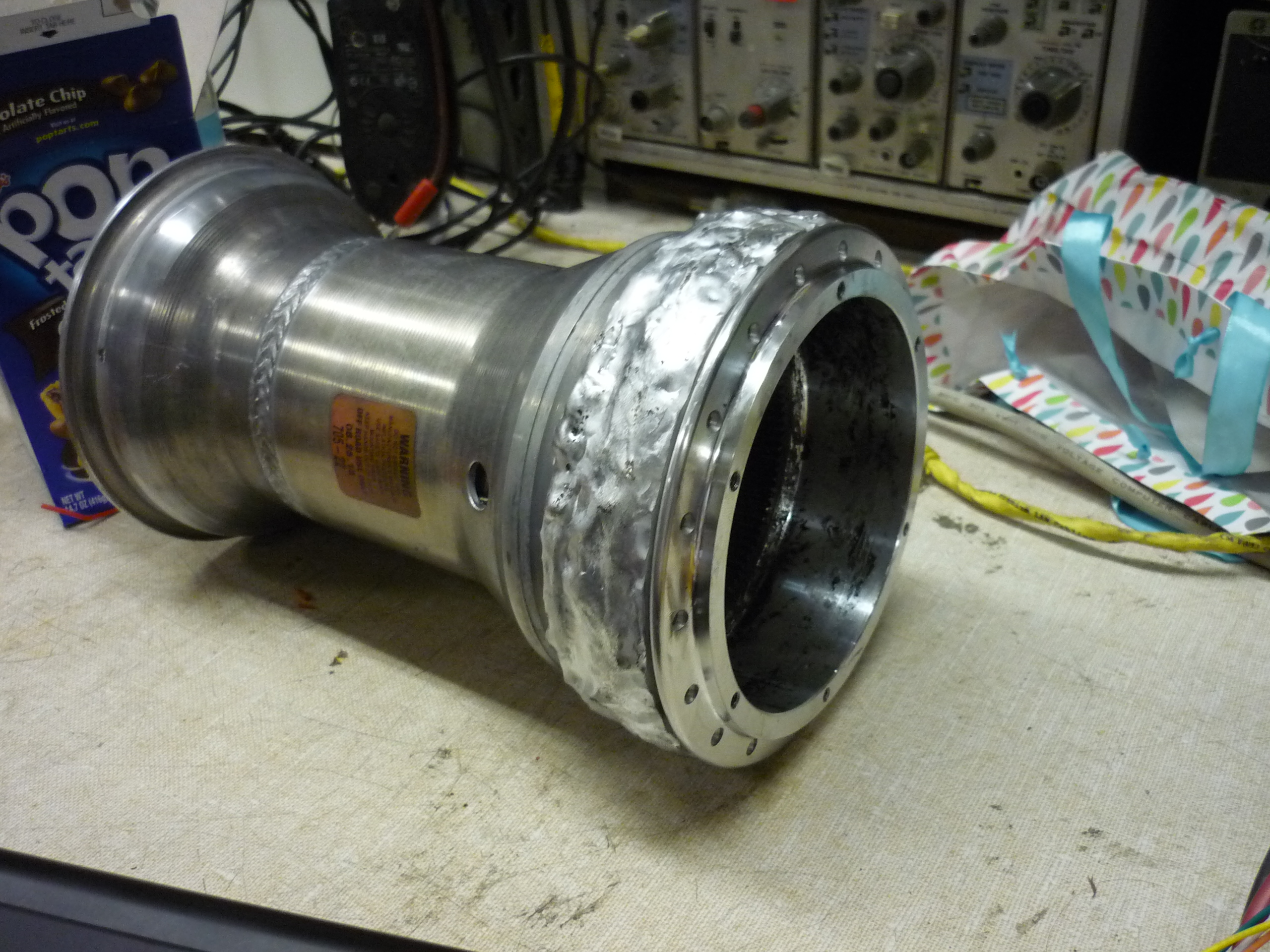 |
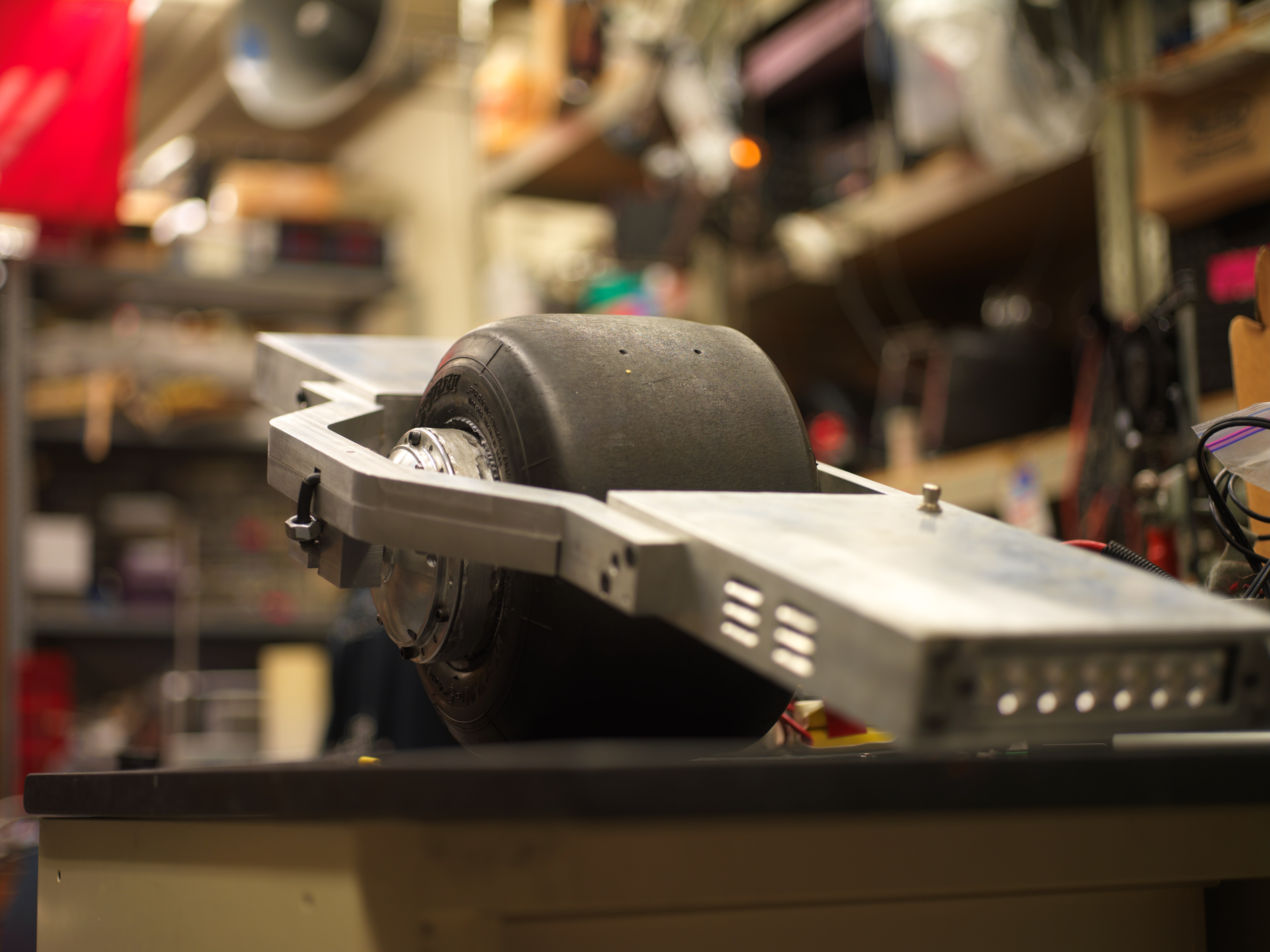
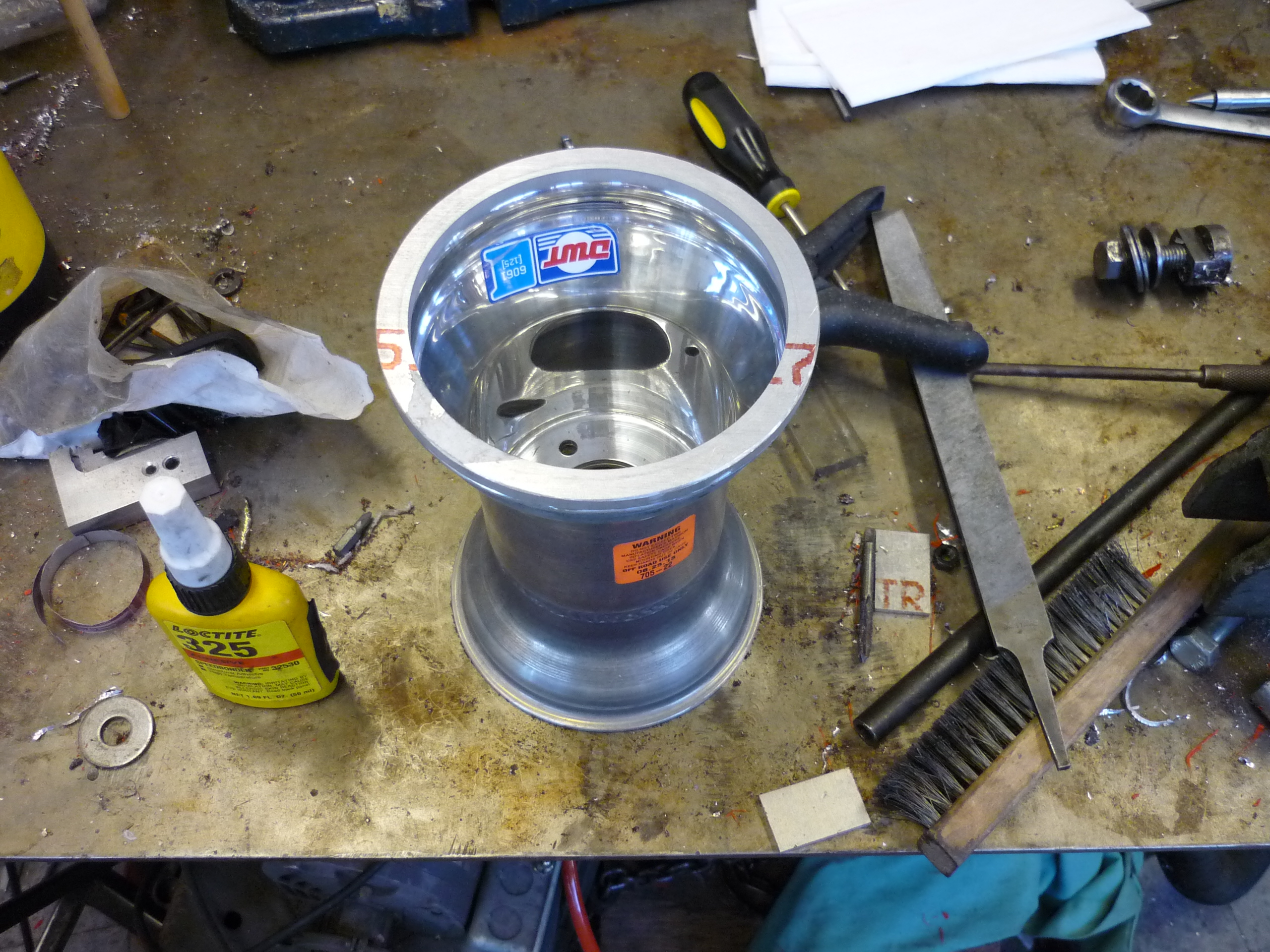
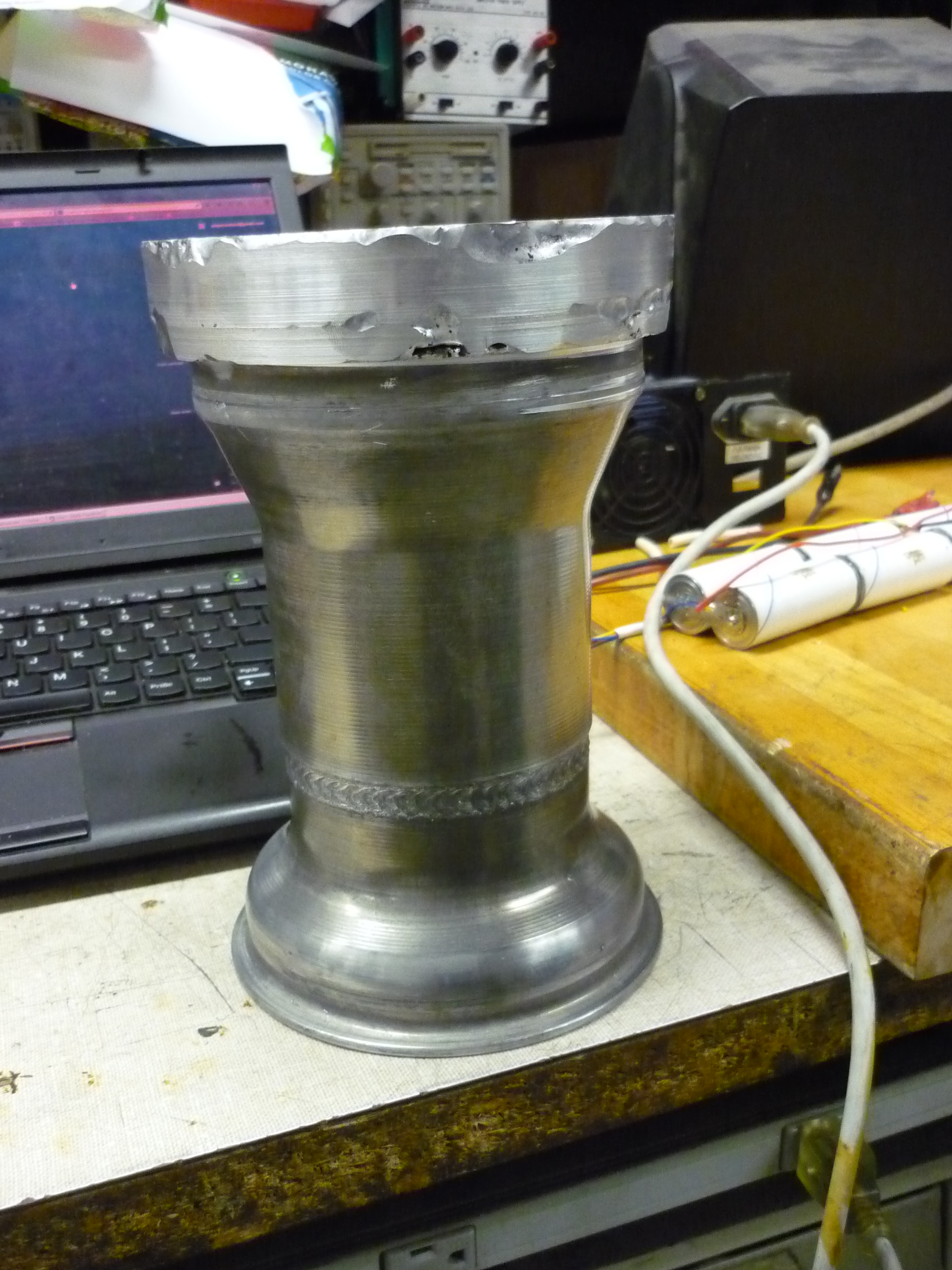
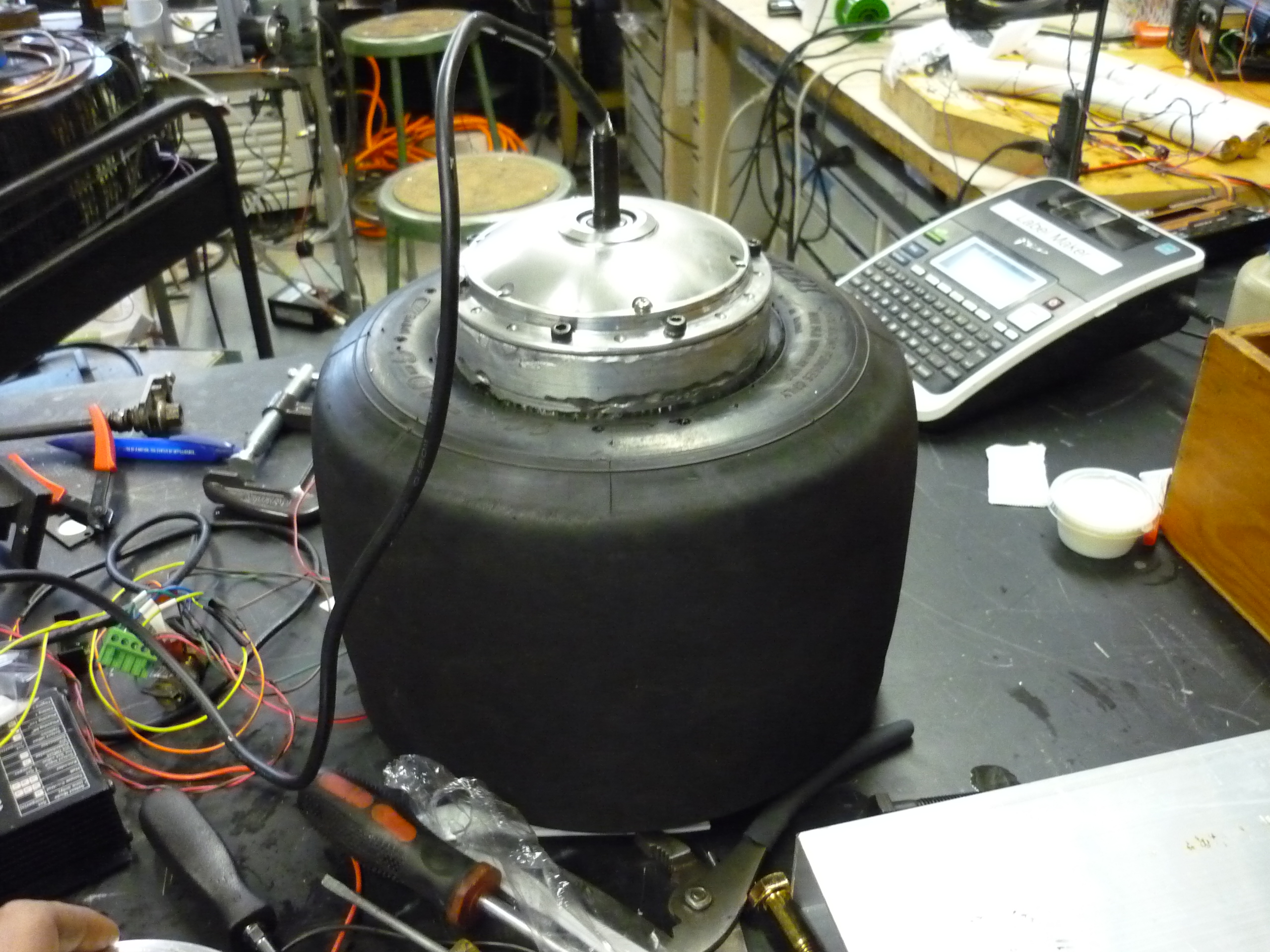
| A final product and a test-fit LIKE A GLOVE. The hub motor fit perfectly into the welded 'extended hub'. Everything slid into place and MITERS's new MONDO-LATHE was used to clean up the outside surface. |
 |
 |
| Top view The lip of the hub-motor is shown lining up with the outside of the extender-rings. The outside of the hub-motor is cast aluminum, but the inside ring gear is steel, which appears to be pressed into the hub. |
 |
 |
| Spool up Holding the hub-motor by its shaft, the whole apparatus was spooled up by the A-M-C controller. It zipped around nearly instantly when I applied 'full power fwd' The whole thing came out fairly well balanced. This was honestly surprising, with the amount of filler rod added and secondary machining, the fact that it was relatively balanced on the spin-axis was exciting. |
 |
 |
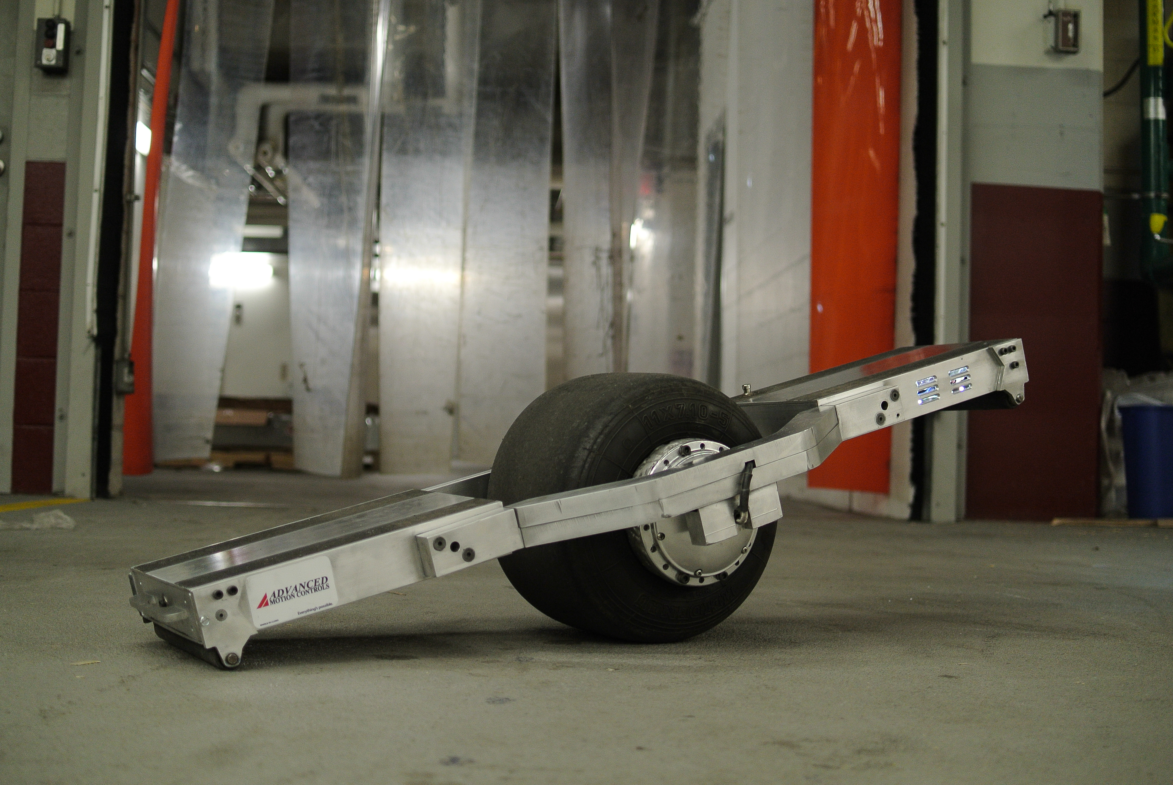
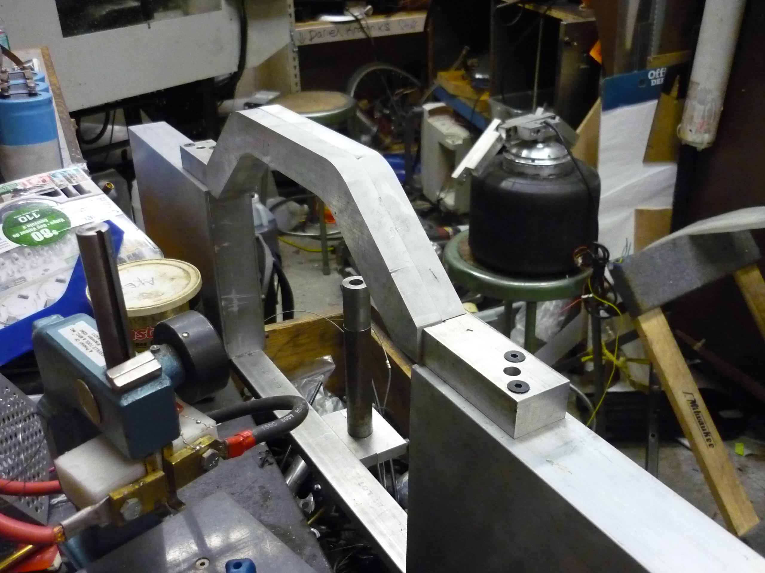
| The Frame |
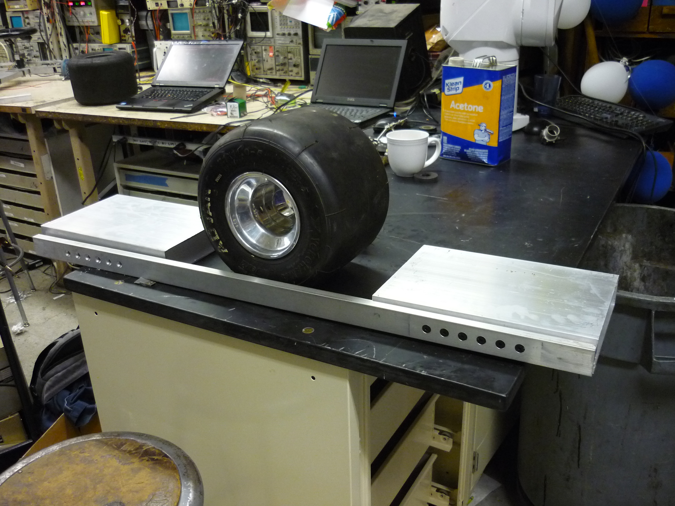
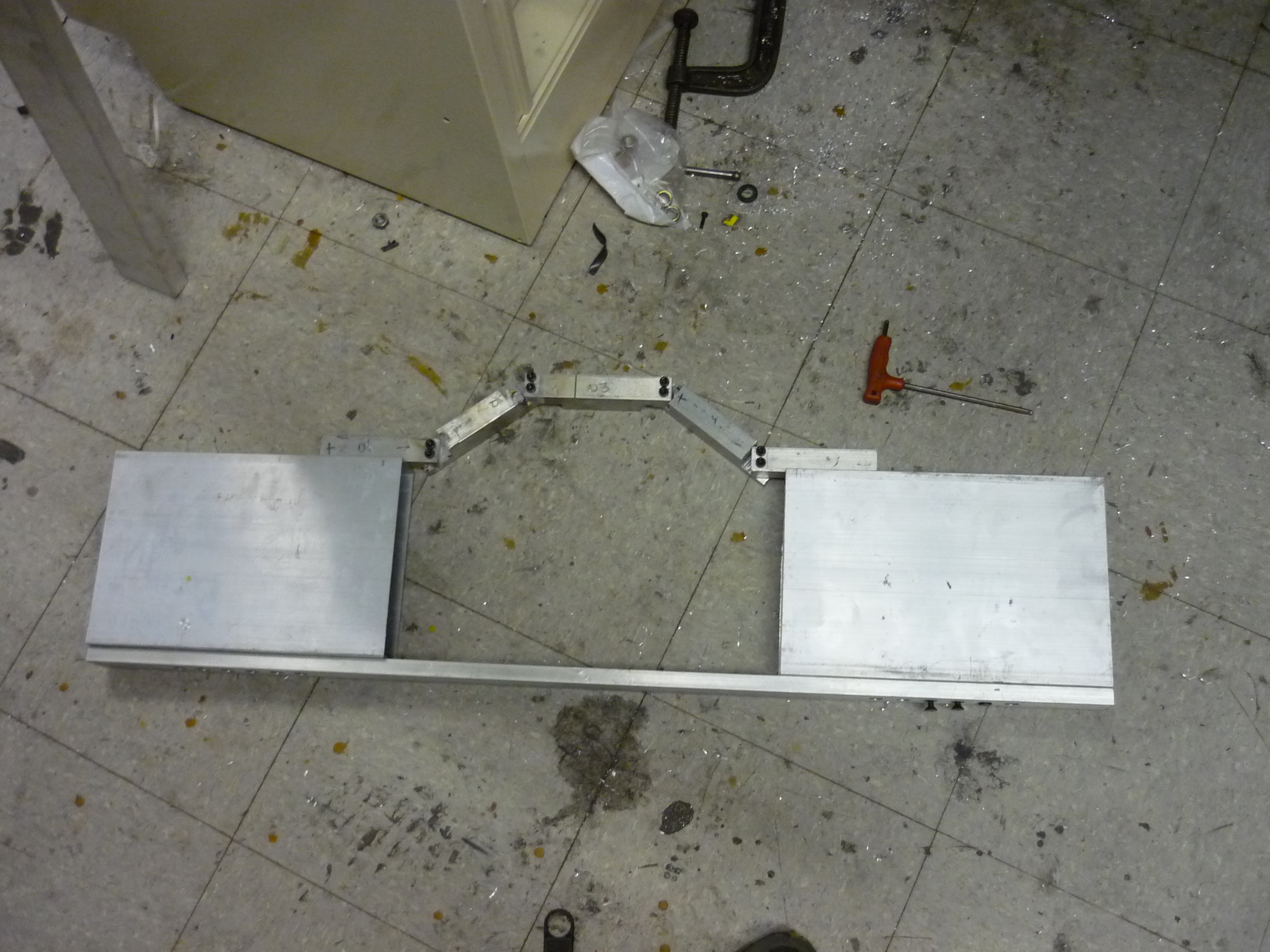
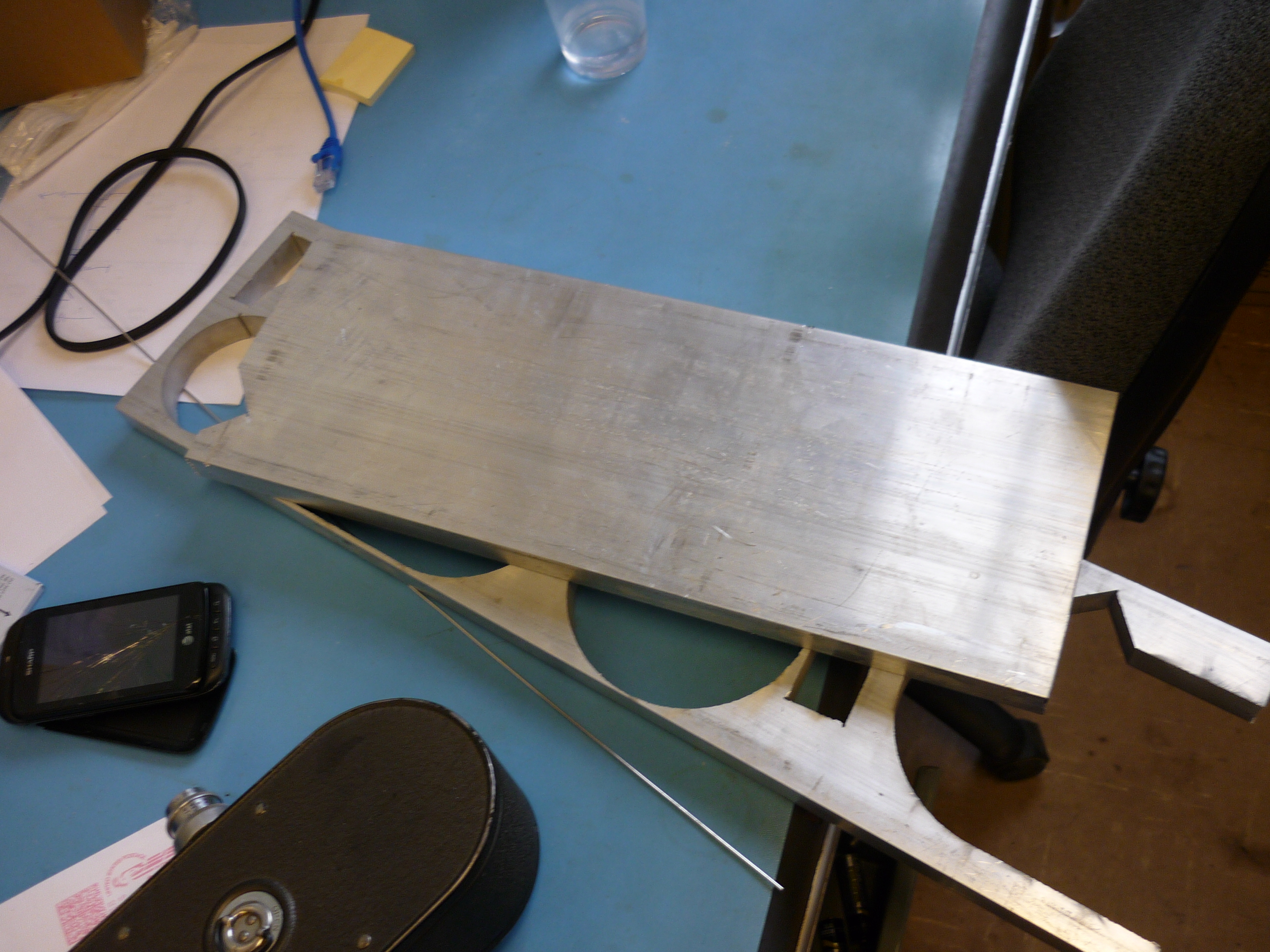
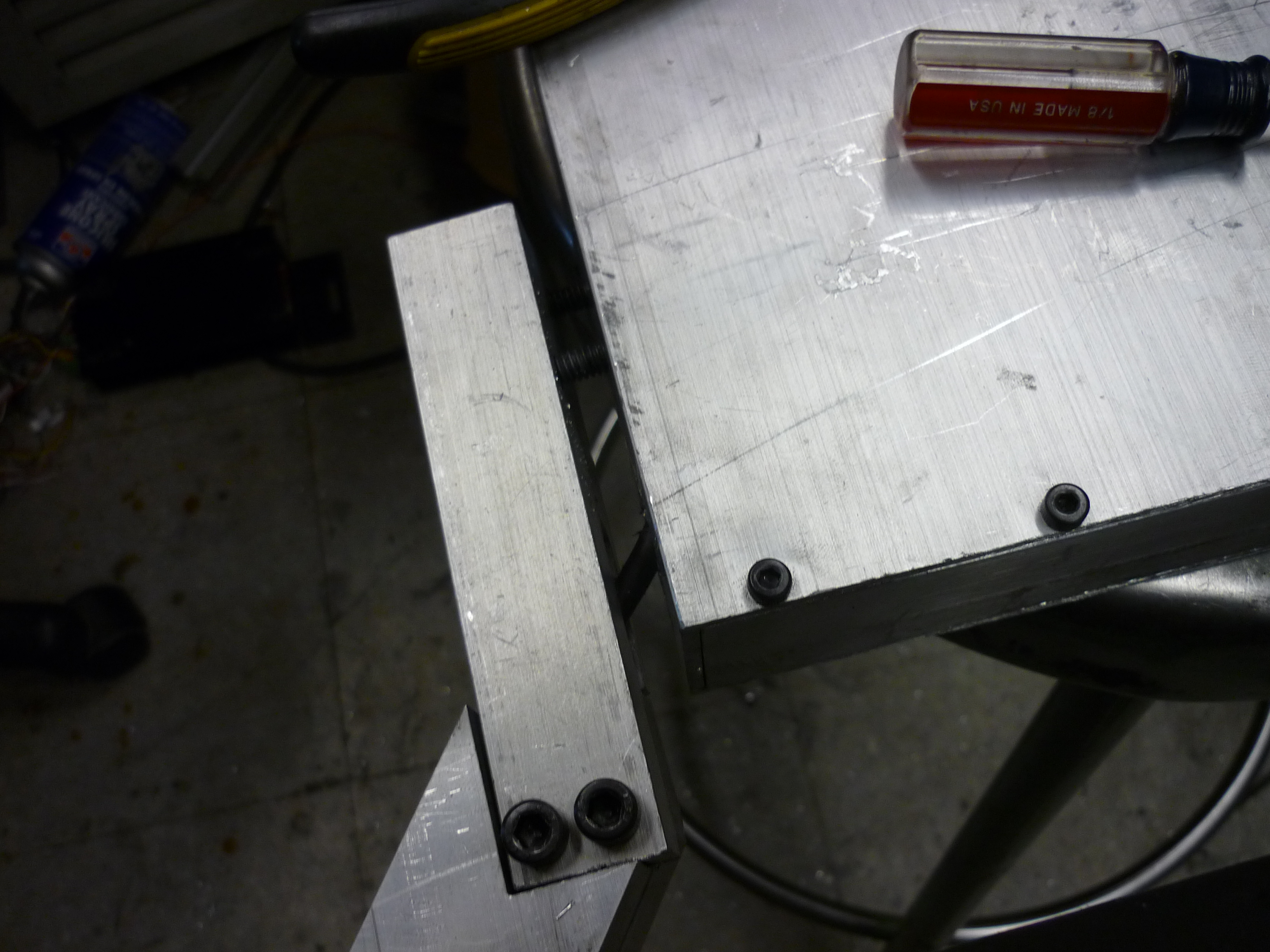
| The vehicle's frame was a fairly lucky find. Two really odd sized aluminum extrusions were found in a pile outside MIT's CSAIL shop in a scrap pile. Each were 1/8" thick 8" x 12" x 2" extrusion, which, would work out excellently for being both a standing platform as well as a cavity for storing batteries, controllers and drive electronics. The solid aluminum bar was also a neat find, from a lab clean out in the physics department, thanks to the Birkel. | 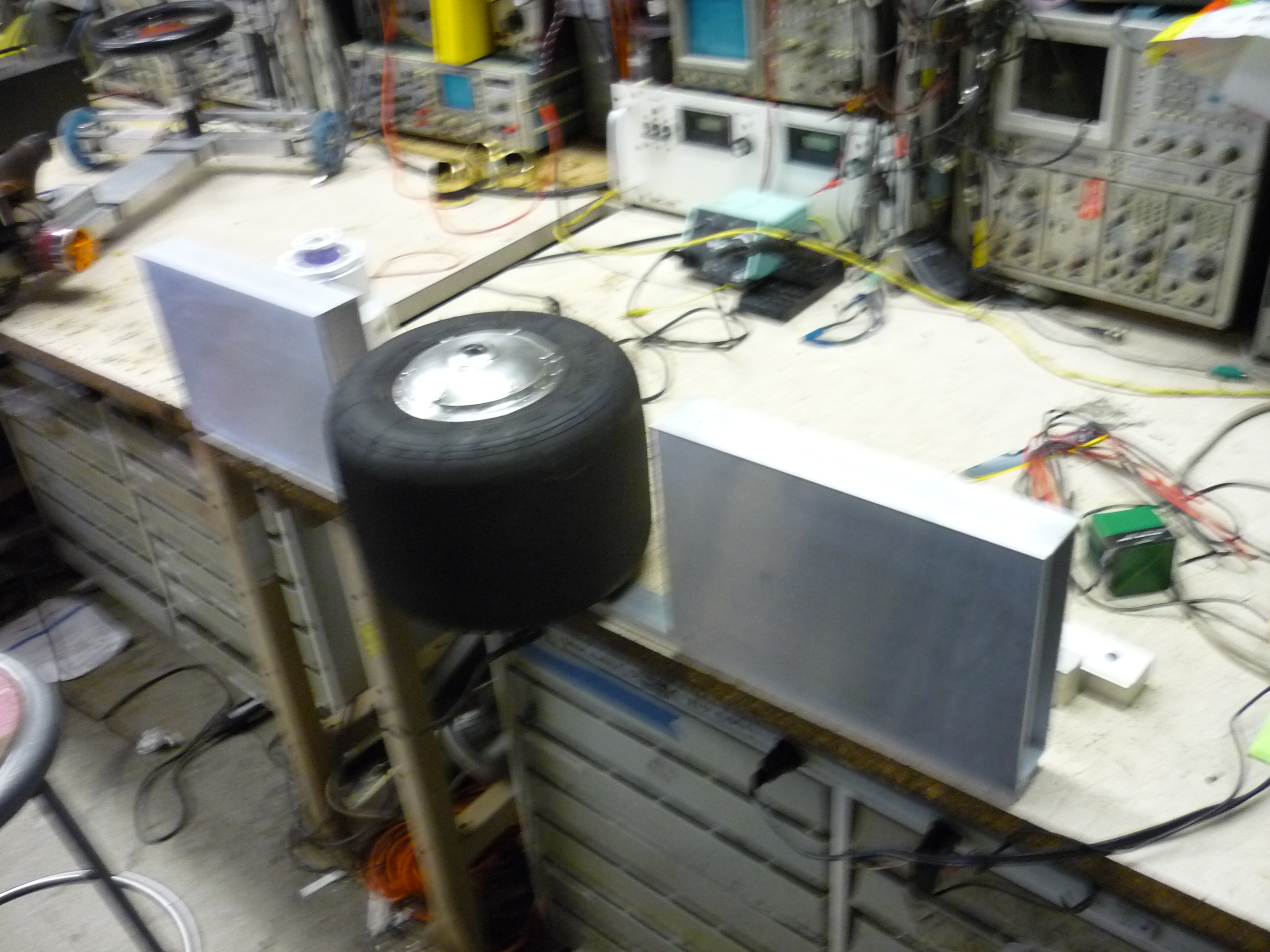 |
 |
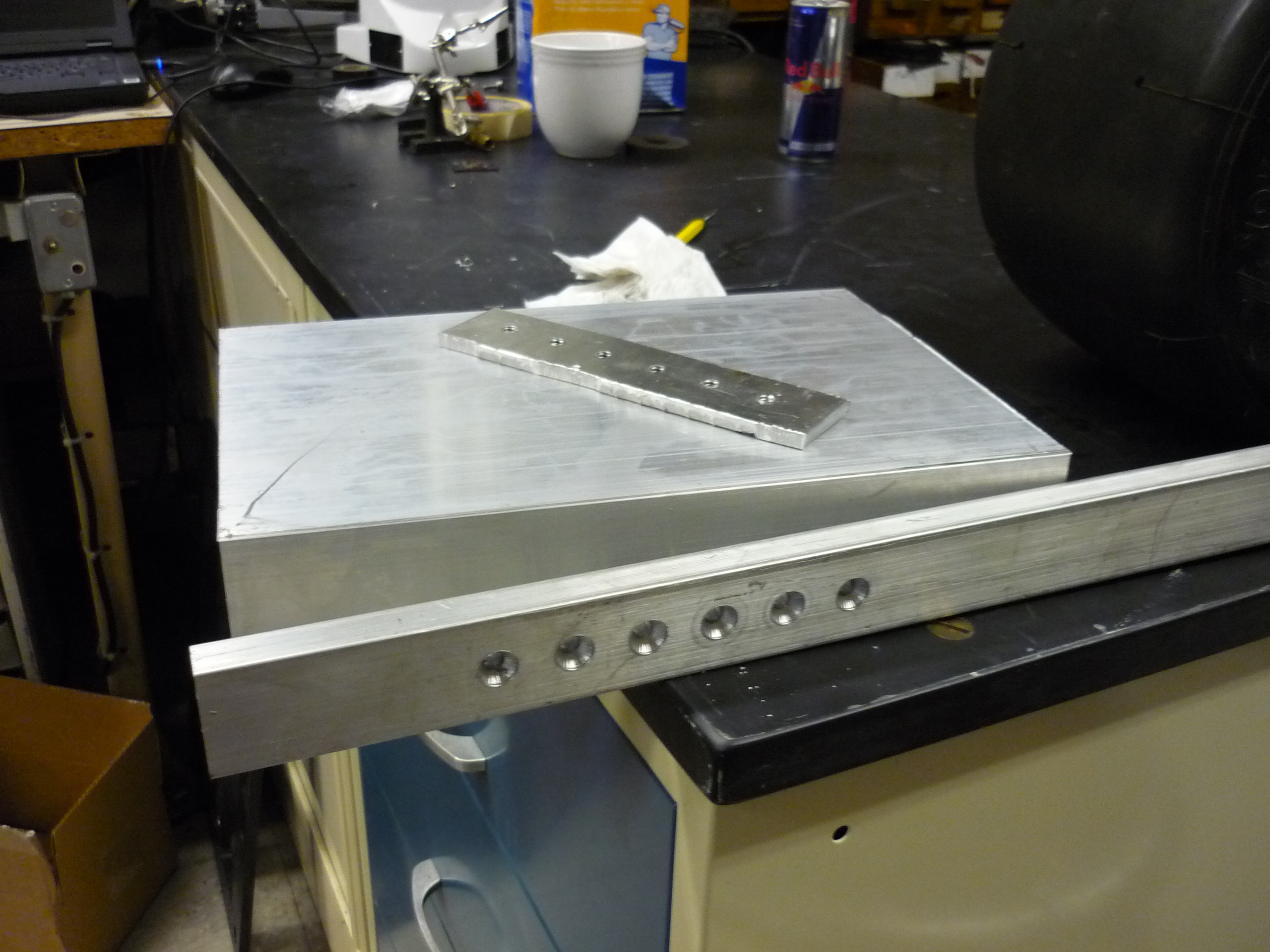
| Let the machining begin Using a Bridgeport mill, I bored out six mounting holes, spaced 1" from each other, for beveled cap-screws. An internal 1/4" thick aluminum plate was tapped and used as the screw-in plate. Tapping the 1/8" thick extrusion wouldn't have been structural enough, while the tapped plate clamped the whole assembly together. Having the tapped plate also meant 'no nuts' floating around inside. |
 |
 |
| The mount was duplicated for the opposing side and then began the raised mount for the hub motor. I opted for having the wheel offset from the center, as this would both provide more ground clearance and also allow for a slower response loop. For inverted pendulum driven contraptions, the higher the offset mass is from the fulcrum point, the easier it is to balance. A simple analogy is that it is easier to balance a broomstick manually than a pencil from an inverted pivot point. | 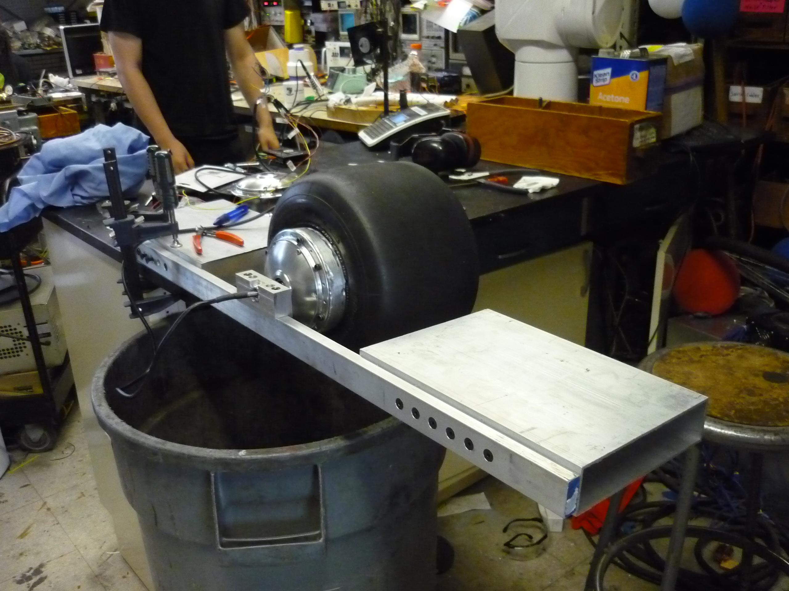 |
 |
After quickly mounting the hub-motor with a clamp, I realized how significantly longer the hub-motor offset was versus what I had anticipated, which resulted in the tire sitting significantly offset from the frame. The previous rim fit more of the hub motor in-line and would not have required as extensive of an offset. Using some scrap aluminum blocks, i fashioned a 'quick' offset mount. Mechanically it was a bit sub-optimal having so many places for pivots and flexure. |
 |
 |
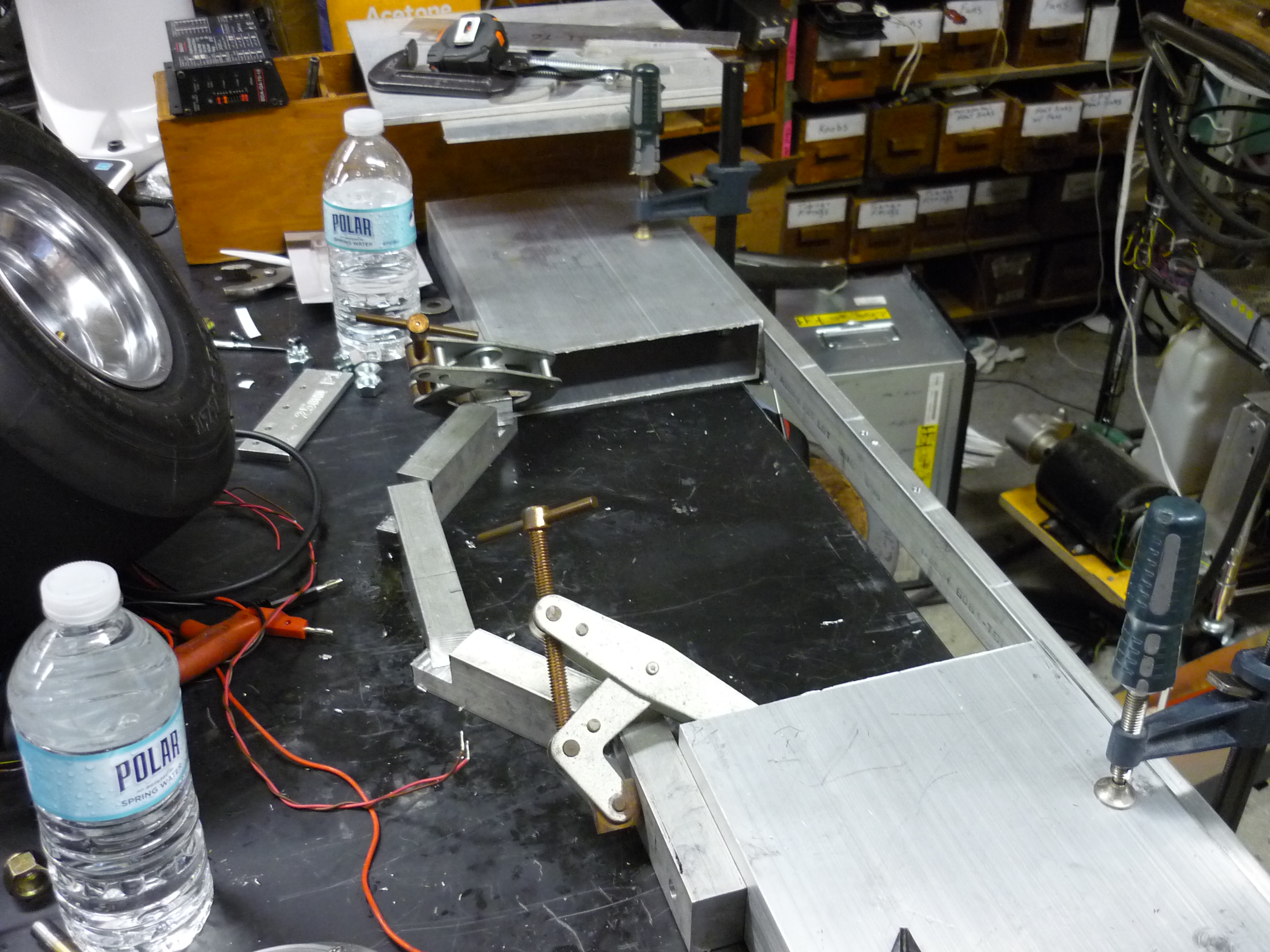
| Clamps clamps clamps Using a pile of miters-clamps, I fashioned up what the whole contraption would look like, and clamped the whole assembly to the black-slab staubli table. |
 |
 |
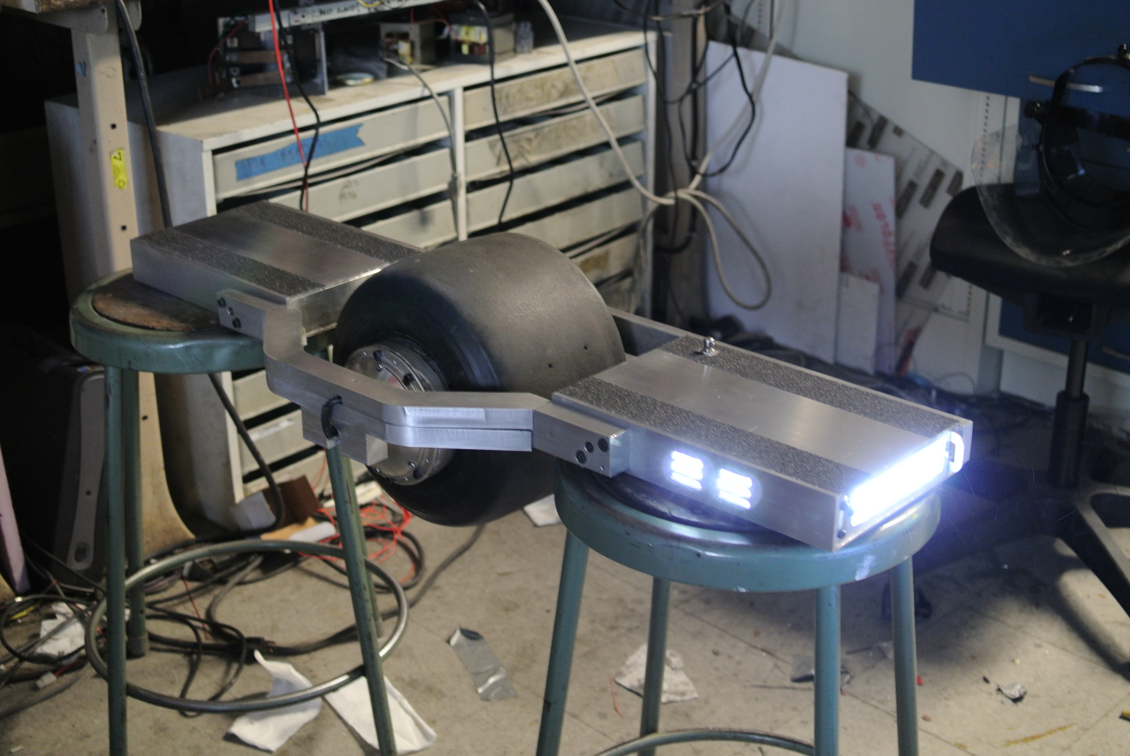
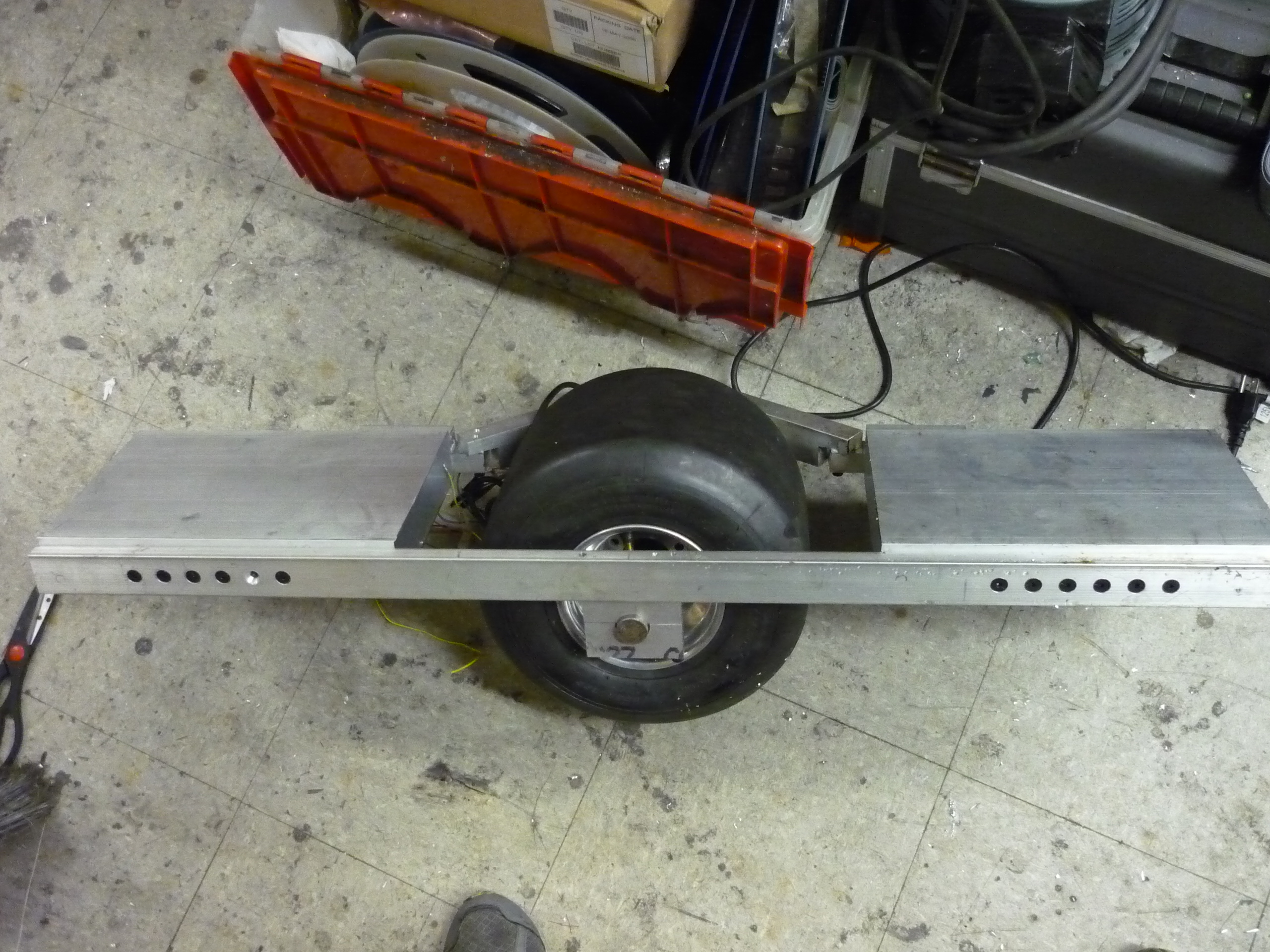
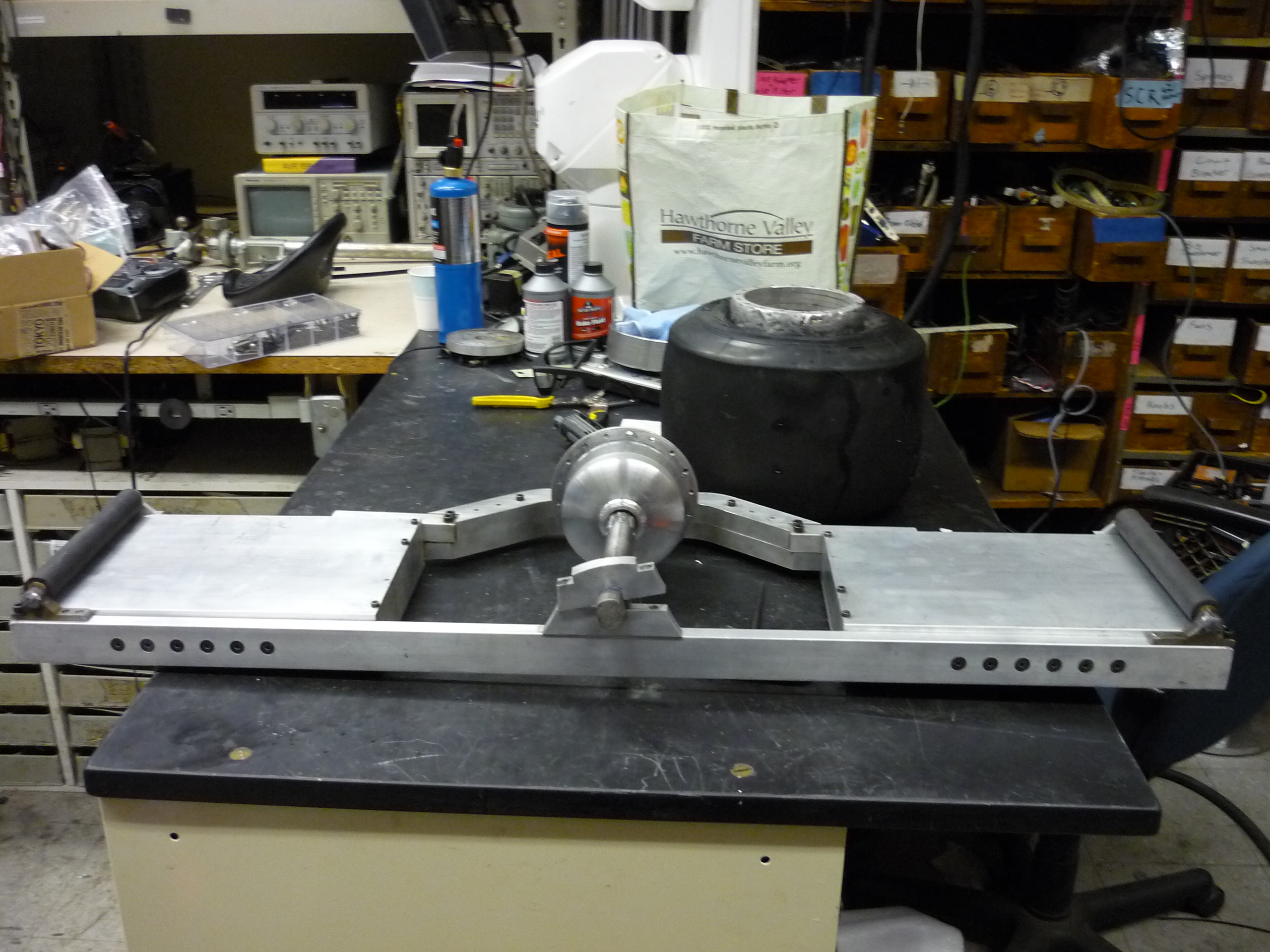
| Behold the mock-up. I continued re-positioning the setup until the layout appeared at the right height for skating around. The clamps served well, and helped point out some interferences from the layout I had initially anticipated. |
 |
 |
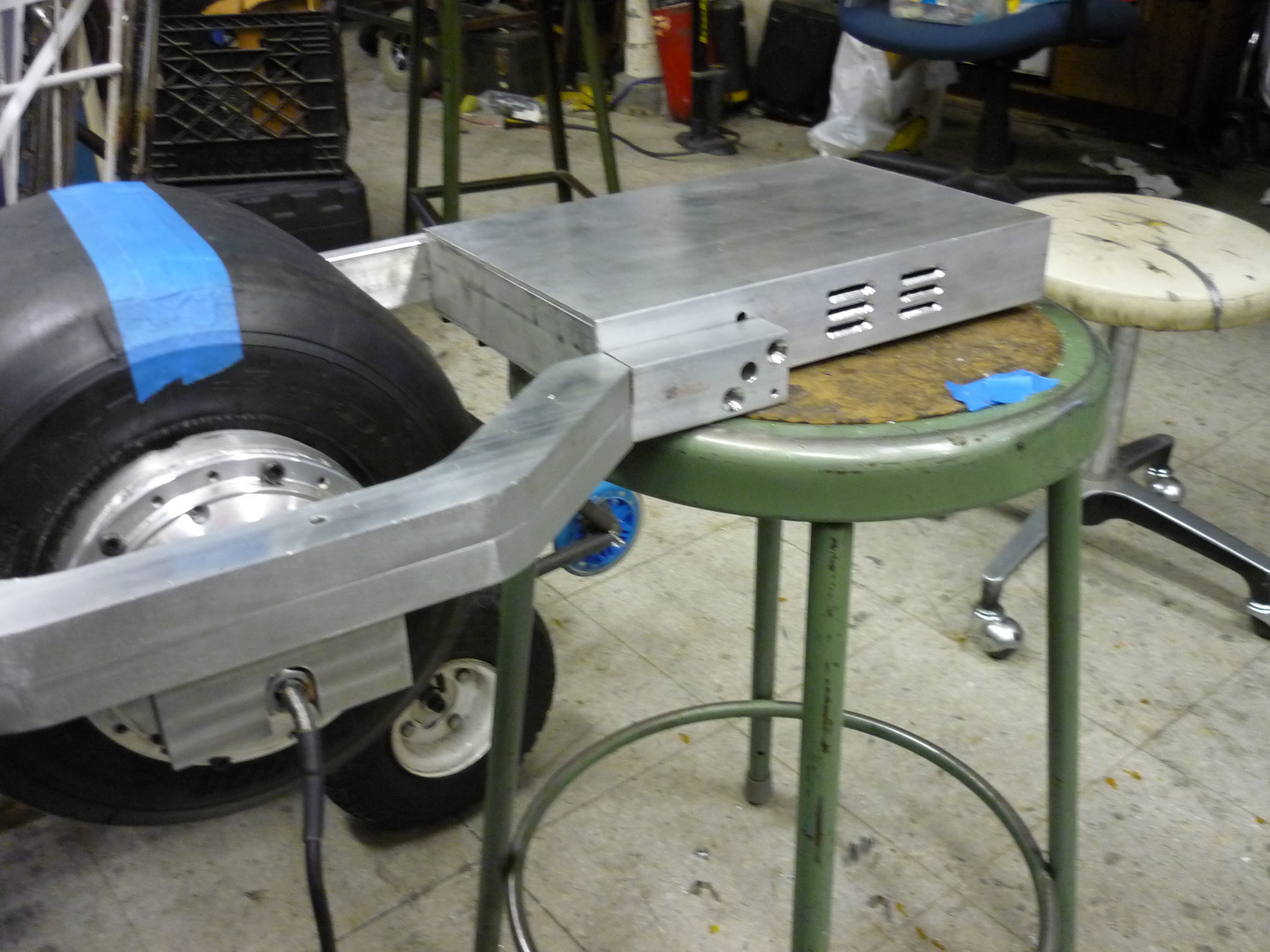
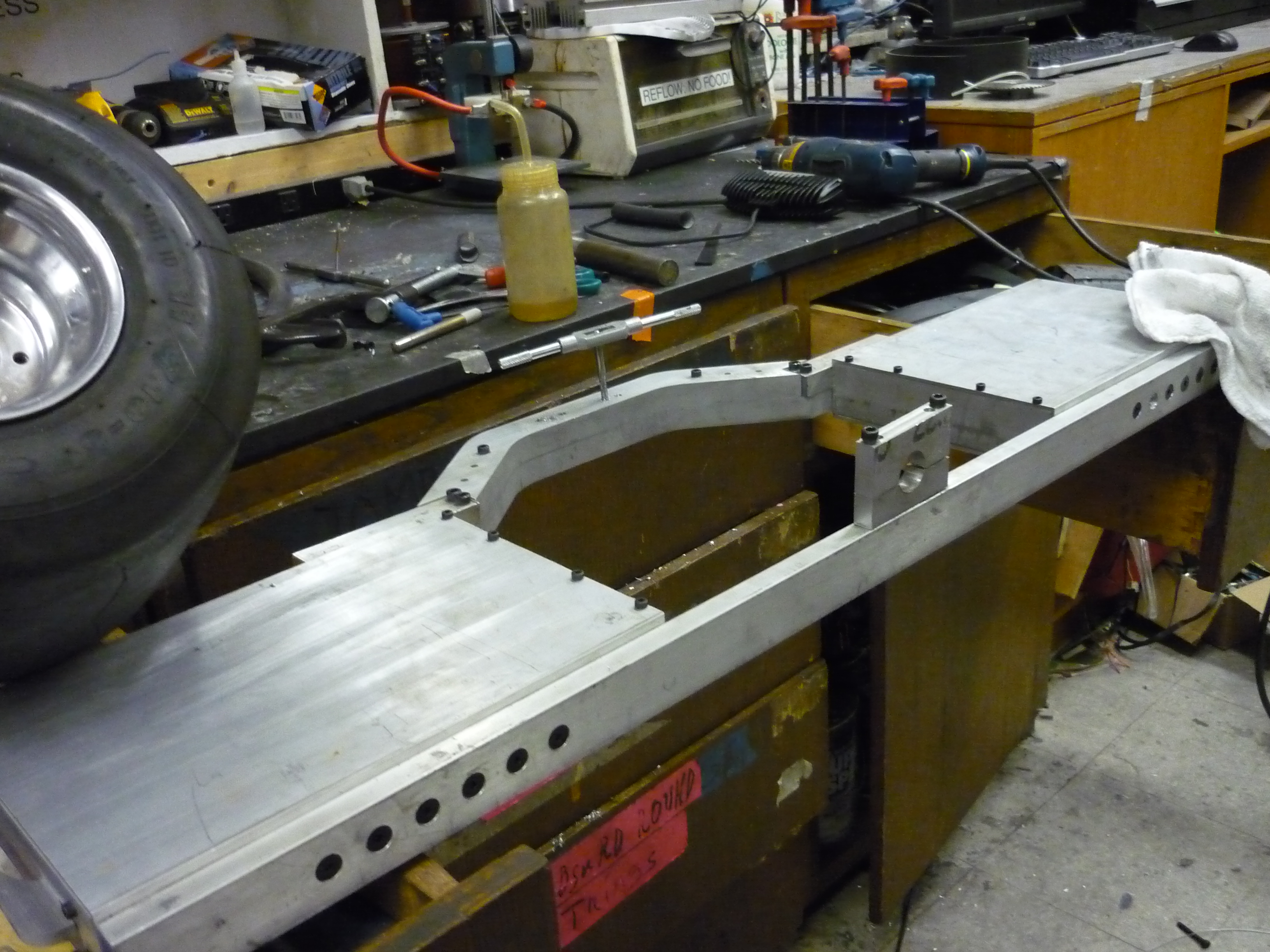
| After an hour of drilling and tapping, I had a rough mock-up. Its huge. At this point in the project the setup is missing the opposing wheel mount, so its not able to support a full person's mass. | 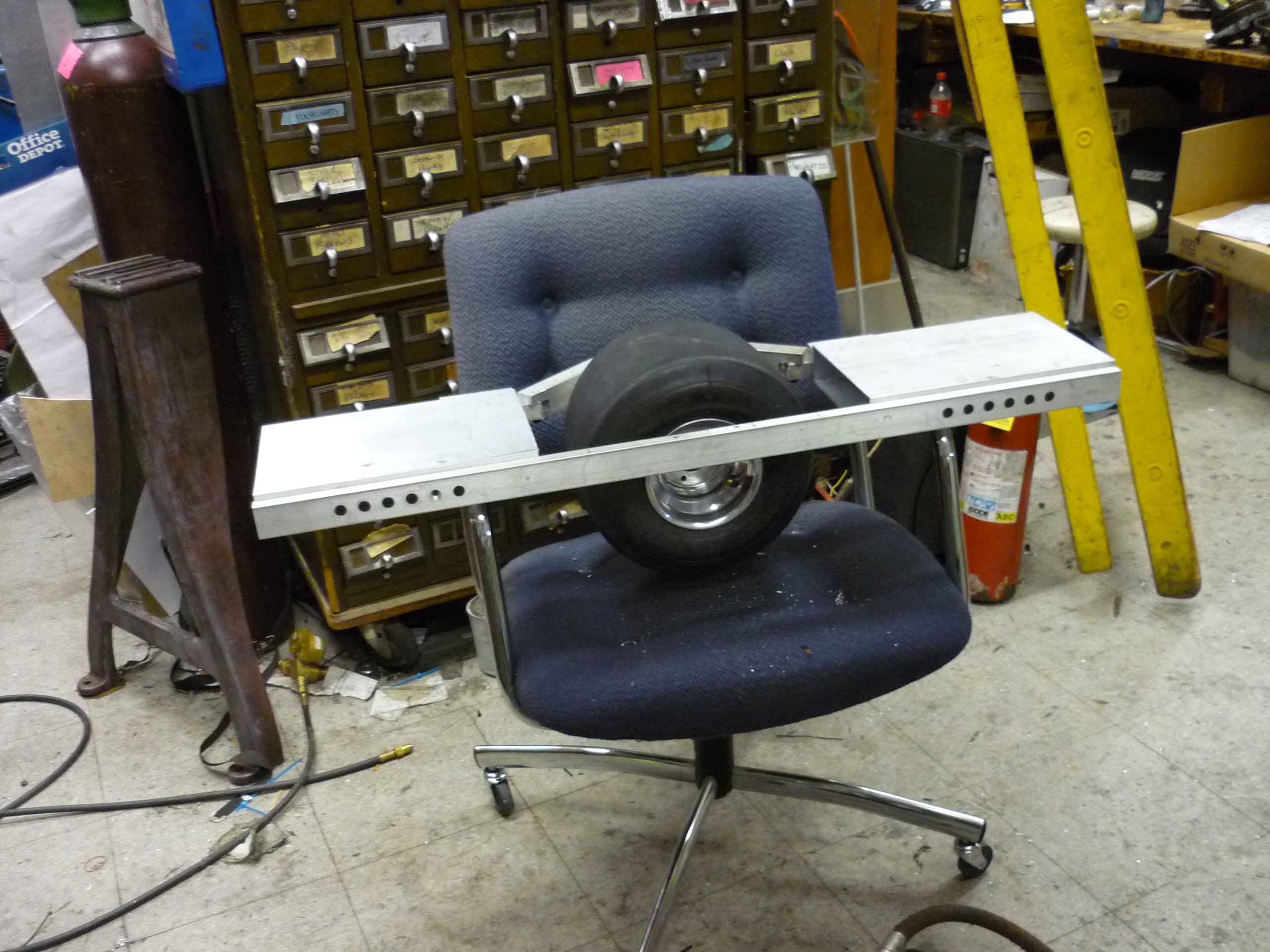 |
 |
| It turned out fairly sleek, and very aluminum-y. It is obviously not balancing electronically in the photo. As shown the wheel is cantelivered at this point, the mount for the other-side was still in the works. I still had mixed feelings about the large angle-connected hub-mounted side of the scooter, and kept an eye out for scrap metal to use for that side. |  |
 |
| The opposing wheel mount There was no way to keep the opposing motor-side of the tire as a single cantilevered connection, so, using a small amount of thick water jet scrap, from CSAIL, A clamping mount was born. While the scrap piece was an odd shape, band sawing it into parts and then using a Bridgeport mill to straighten it out worked well. I started with a bottom mount, using a 1" diameter steel post to act as the mating surface. |
 |
 |
| A similar sized portion of the clamping mechanism was fabricated. Two M6 Bolts tap into the upper mating bar. The riders mass keeps these bolts in compression. It can use some edge-sanding (or routing) but as a first-pass it seemed to work well. | 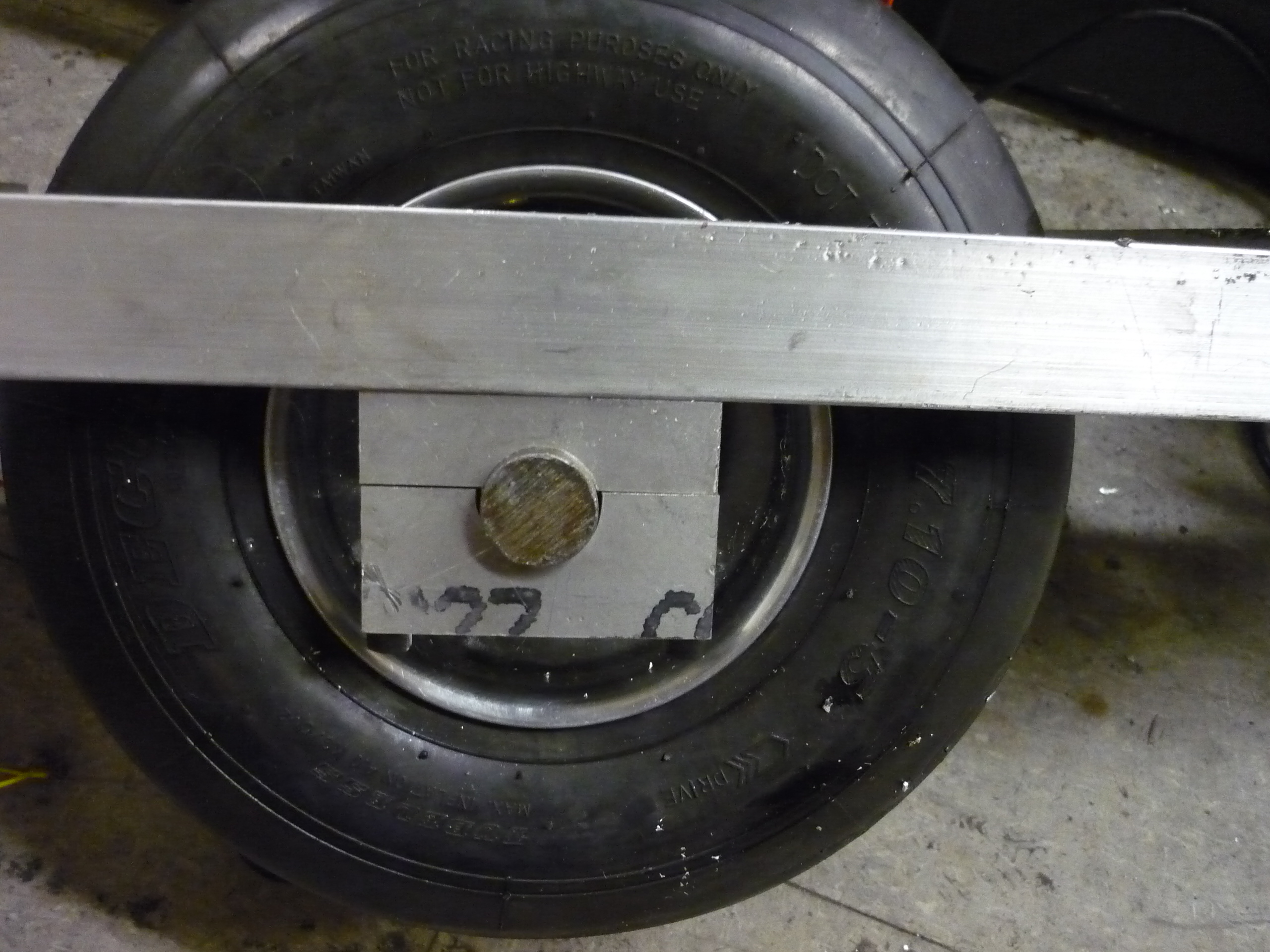 |
 |
| The Frame | |
| First test of the
spooled-up wheel + frame assembly |
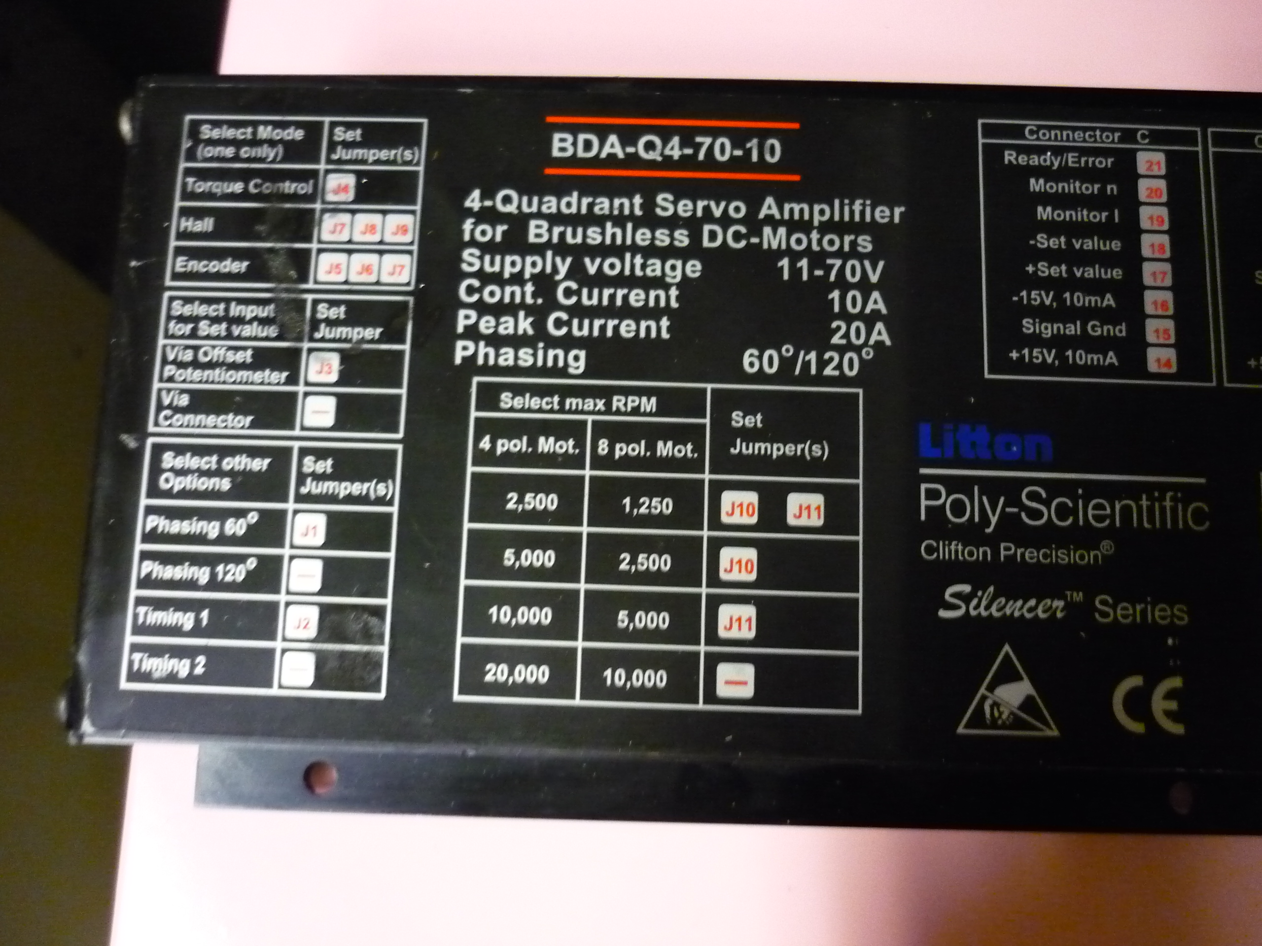
| Litton Poly-Sci Motor Controller Trials and Tribulations, frame upgrades. |
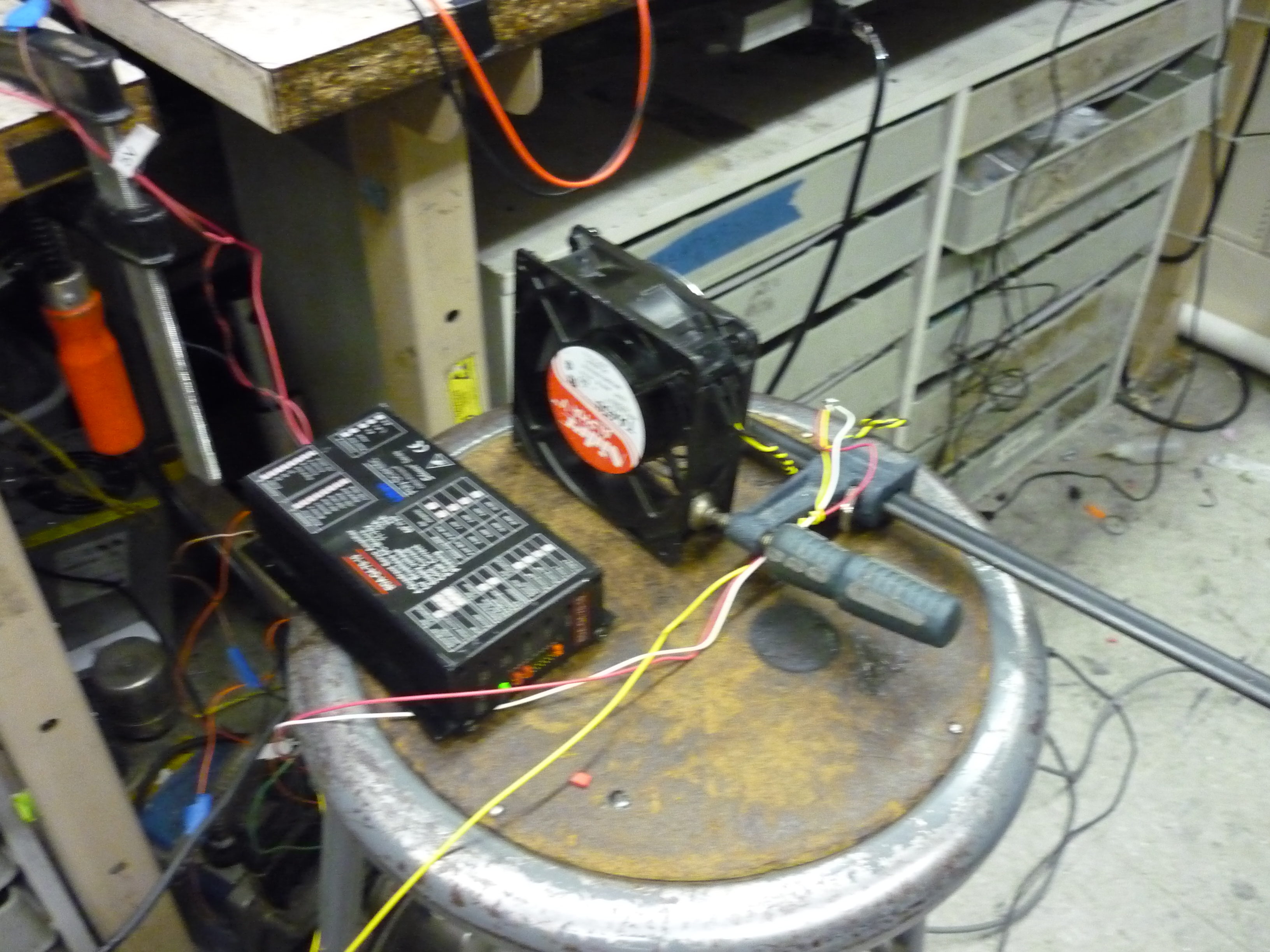
| I fired up the motor controller to no-load verify that the motor and everything was happy, only to find out, a short while later, the littelton poly-sci controller would routinely overheat. With the motor controller mounted inside the aluminum casing (starting at ambient temperature) it would overheat in no-load conditions (spinning the motor without any mechanical loading) within ~3 minutes and 48 seconds. This was a bit frustrating, as an 'overheat' would cause the vehicle to crash. Remaining tests that evening were with forced air from a large 120vac fan. |  |
 |
| After the
overheating I opened the case to take a look as to why
this was happening at low load, as it turned out, the
mosfets used were fairly high impedance (44 mili-Ohms)
on resistance. Thats a boatload! Fortunately there were some 14mOhm n-channel TO-220 mosfets of a slightly lower max voltage hiding in miters. After a bit of soldering and positioning I was able to swap one in at a time and fire up the drive. |
 |
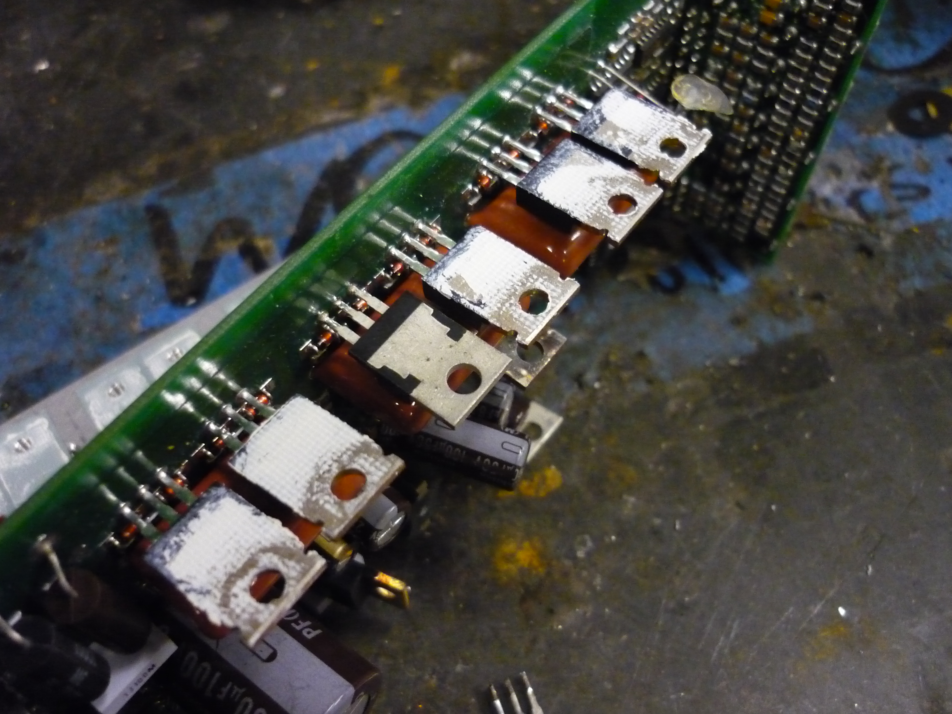 |
| One by one All of the TO-220 fets were replaced and, with some thermal paste, the servo drive was put back together. While the gate charge for this new fet was almost identical, its lower on-resistance should have saved me a bit of lost power. |
 |
 |
| Oh dear. On closer inspection, this servo drive appears used the mosfets on-state impedance as a part of its current measuring mechanism. With the swapped fets, everything worked, but sounded horrible with significantly higher steady state power consumption. Steady state consumption moved from 0.5A to ~5A. SUB-OPTIMAL! it still spun up, but was audibly louder. |
 |
 |
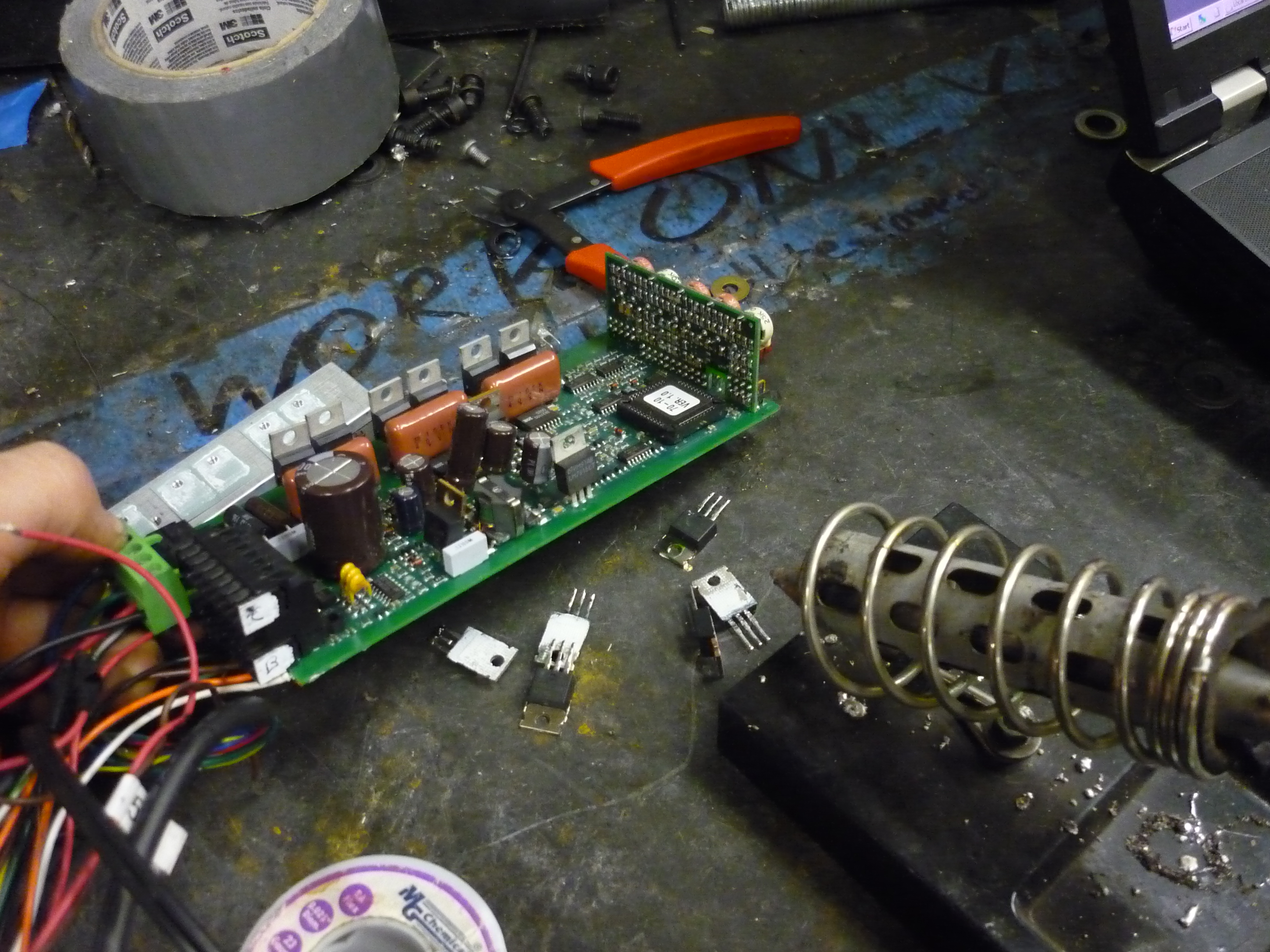
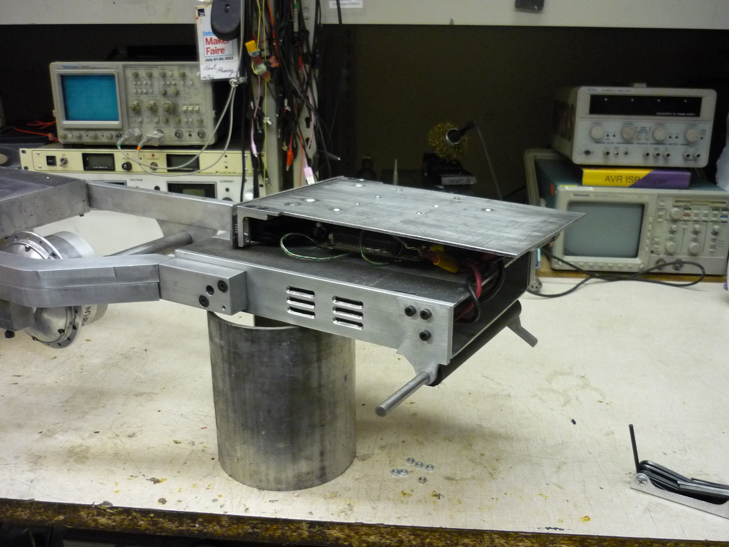
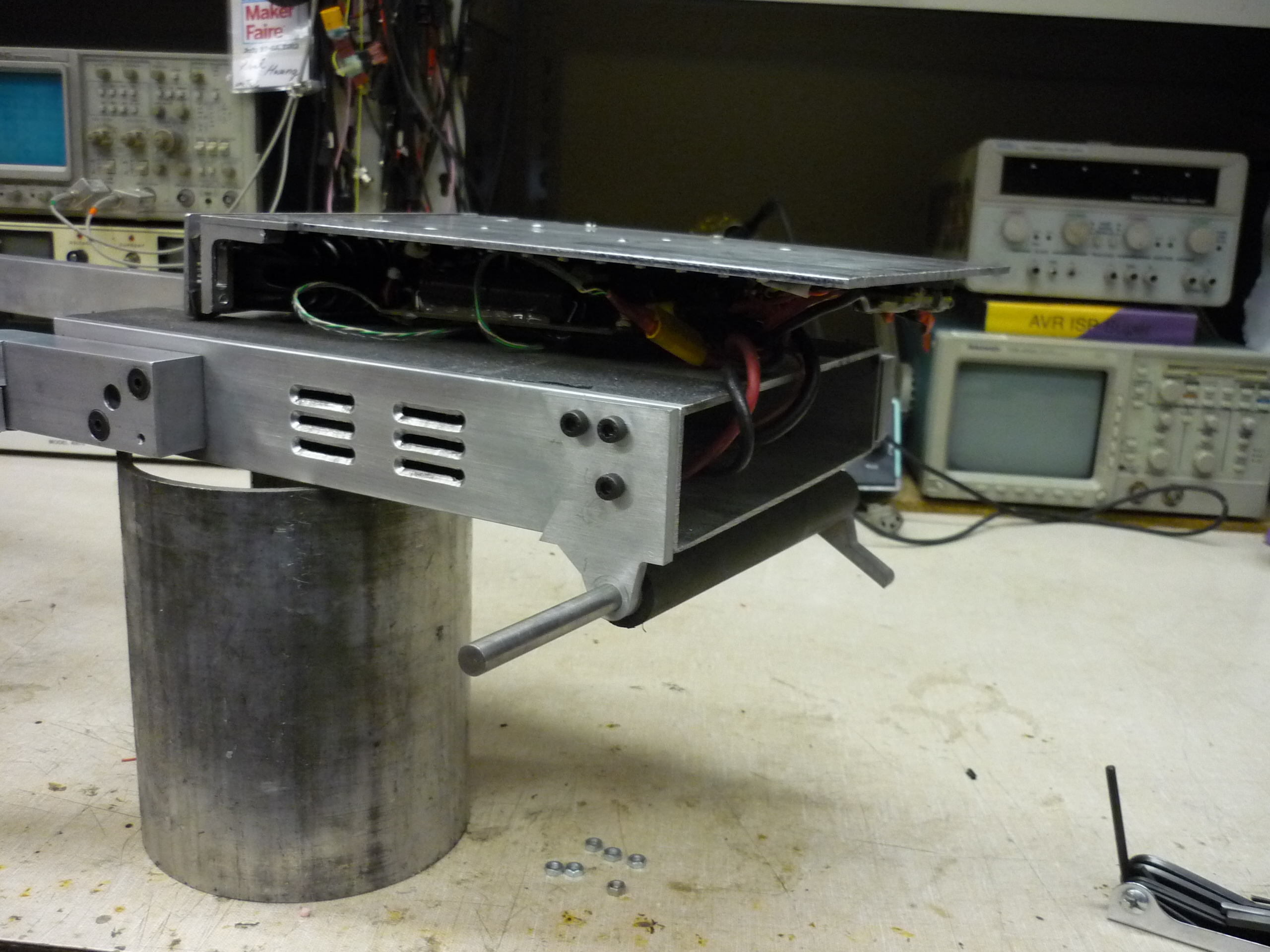
| Giving In With forced air cooling the motor controller did not seem to have too much of a problem, so I opted to include an air cooling path. I used a Bridgeport mill and a v-shaped cutter to get the 'vent' angles shown. The swing-arm was disconnected in these photos. The drive's fets were swapped back to the 44miliohm ones and testing continued. |
 |
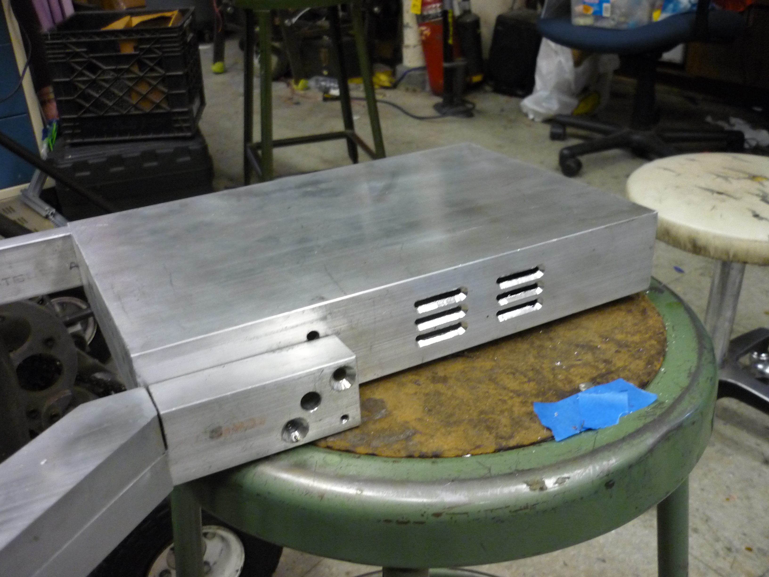 |
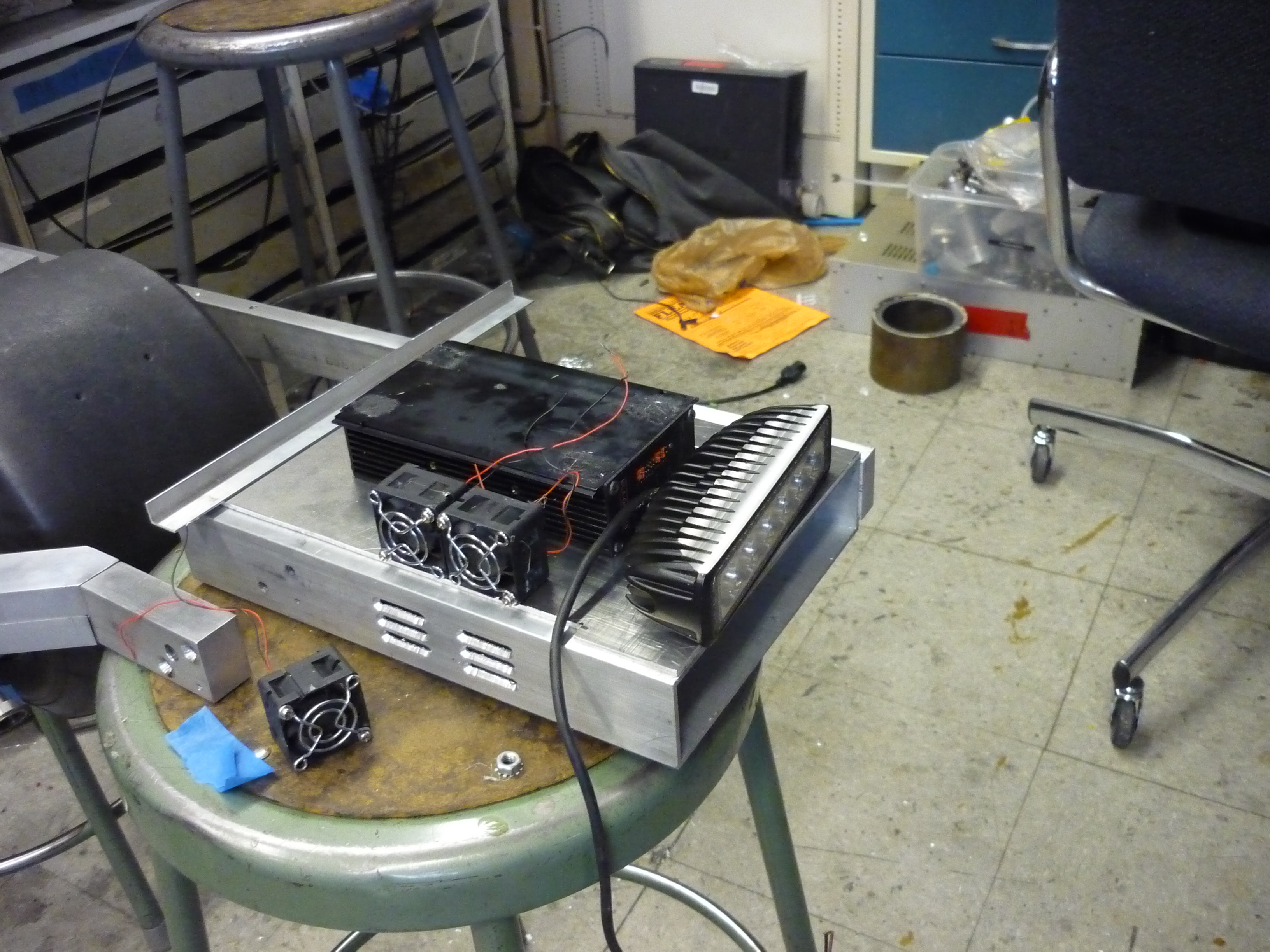
| Rough
placement. The fans used are tiny 40mm server fans, just tall enough to fit in the cavity of the skateboard frame. Due to the physical size of the drive there was not a lot of available room for adding fan-mounts, so i opted to tap the fans into the motor housing. The fans line up with the inlets and exhaust through the front of the scooter through gaps in the headlight mounting. This is far preferred over having the vents line up in the tire-well of the skateboard, sucking up all the tire-wash. |
 |
 |
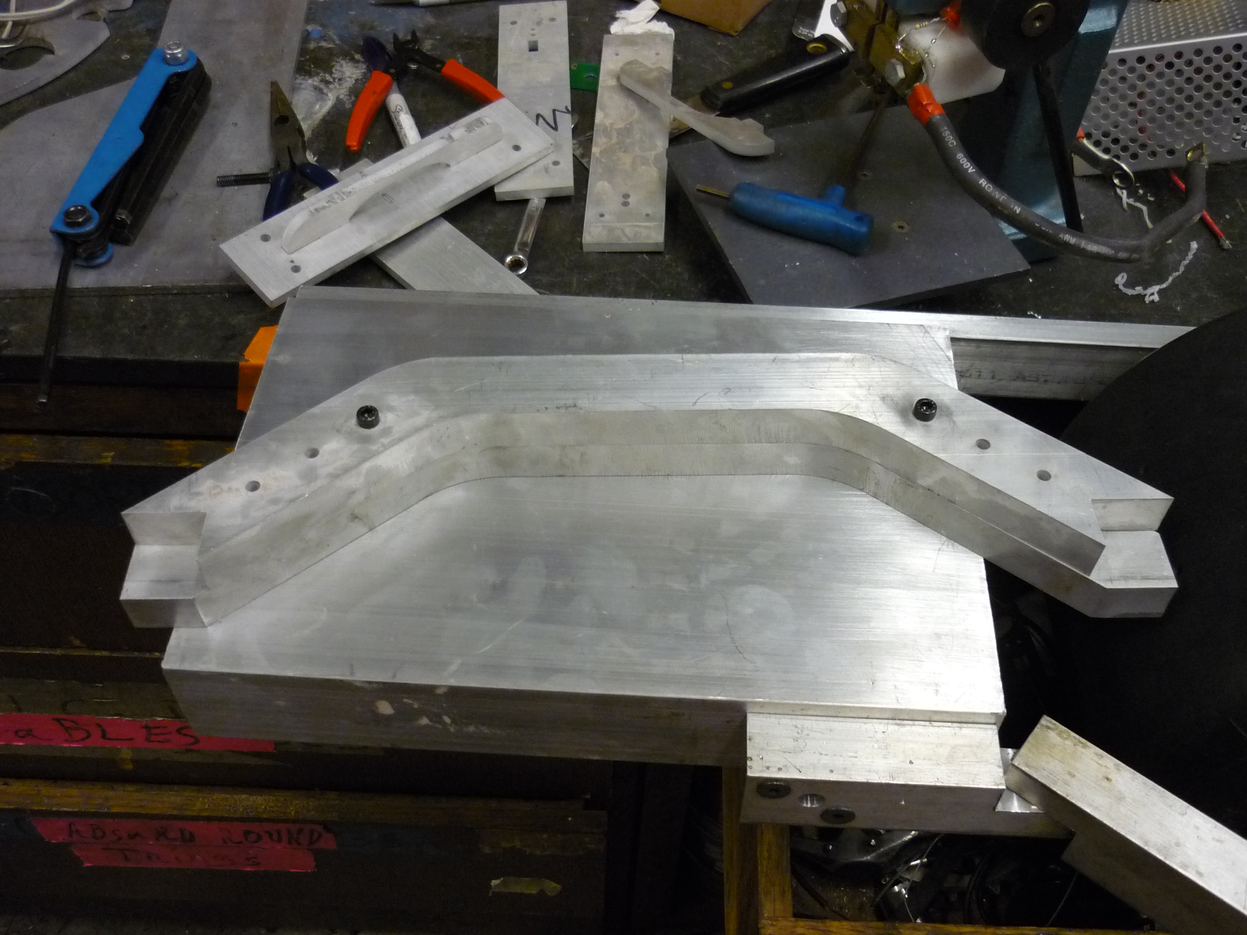
| Frame
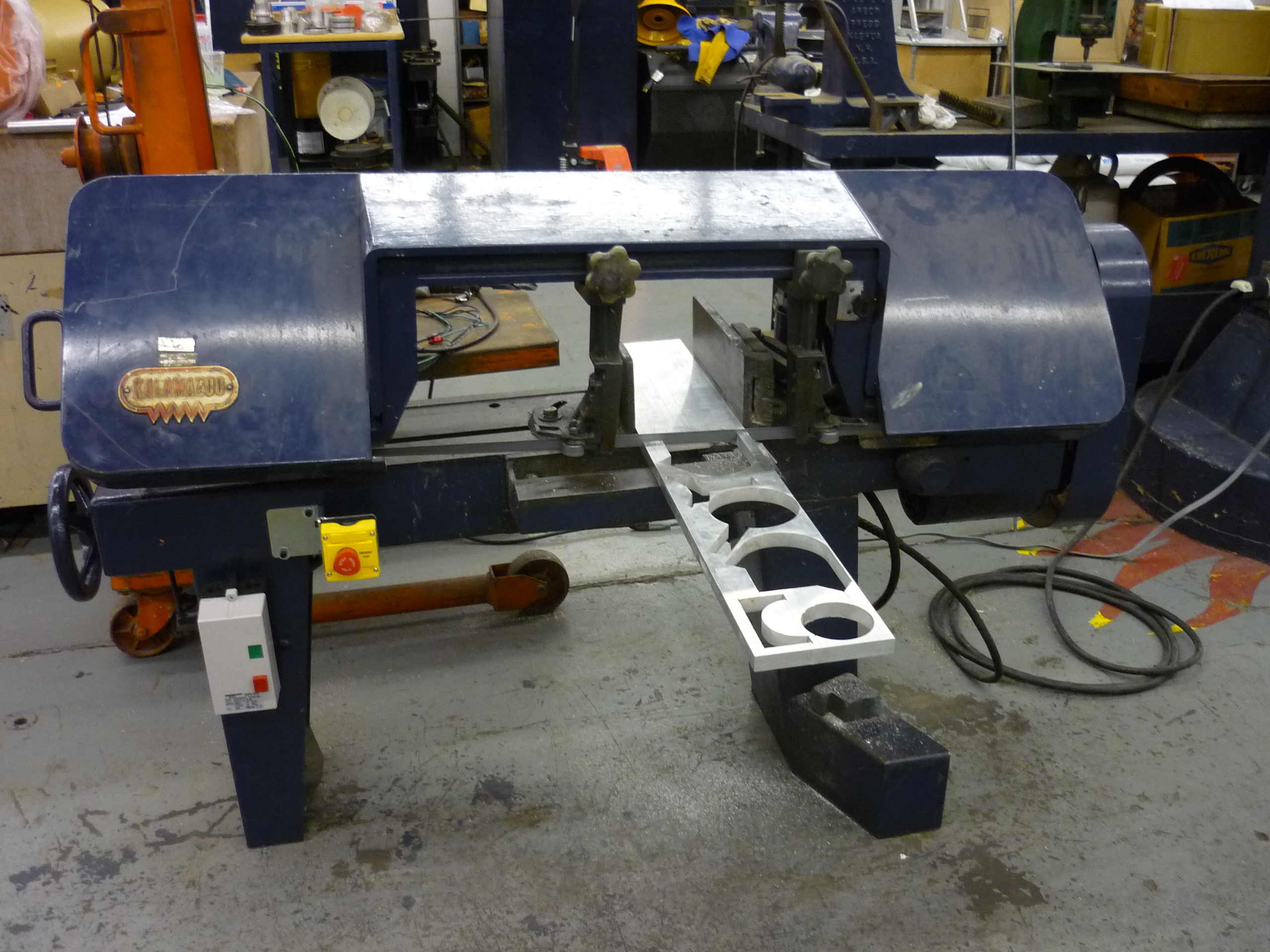
upgrades A huge slab of partially water jet aluminum appeared! 0.75" thick 6061 with a pile of cutouts was scrounged up by a comrade. Recycling at its finest! It was just enough to fit two cutouts for the swing-arm (mentioned earlier). I used the NRL's GINORMOUS horizontal band saw to cut the part to size for water jetting. Shown far right is the leftovers. |
 |
 |
| FIRE UP
THE JETS MR BCHAN! I hauled the 0.75"thick reclaimed 6061 plate over to hobbyshop land and went to work. As it was mid-summer the building water temperature was high and causing the pump to enter a fault mode, so, sheets of ice were added to keep the water jet happy. The two parts lined up perfectly! The notches are actually for the skateboard mount point blocks. |
 |
 |
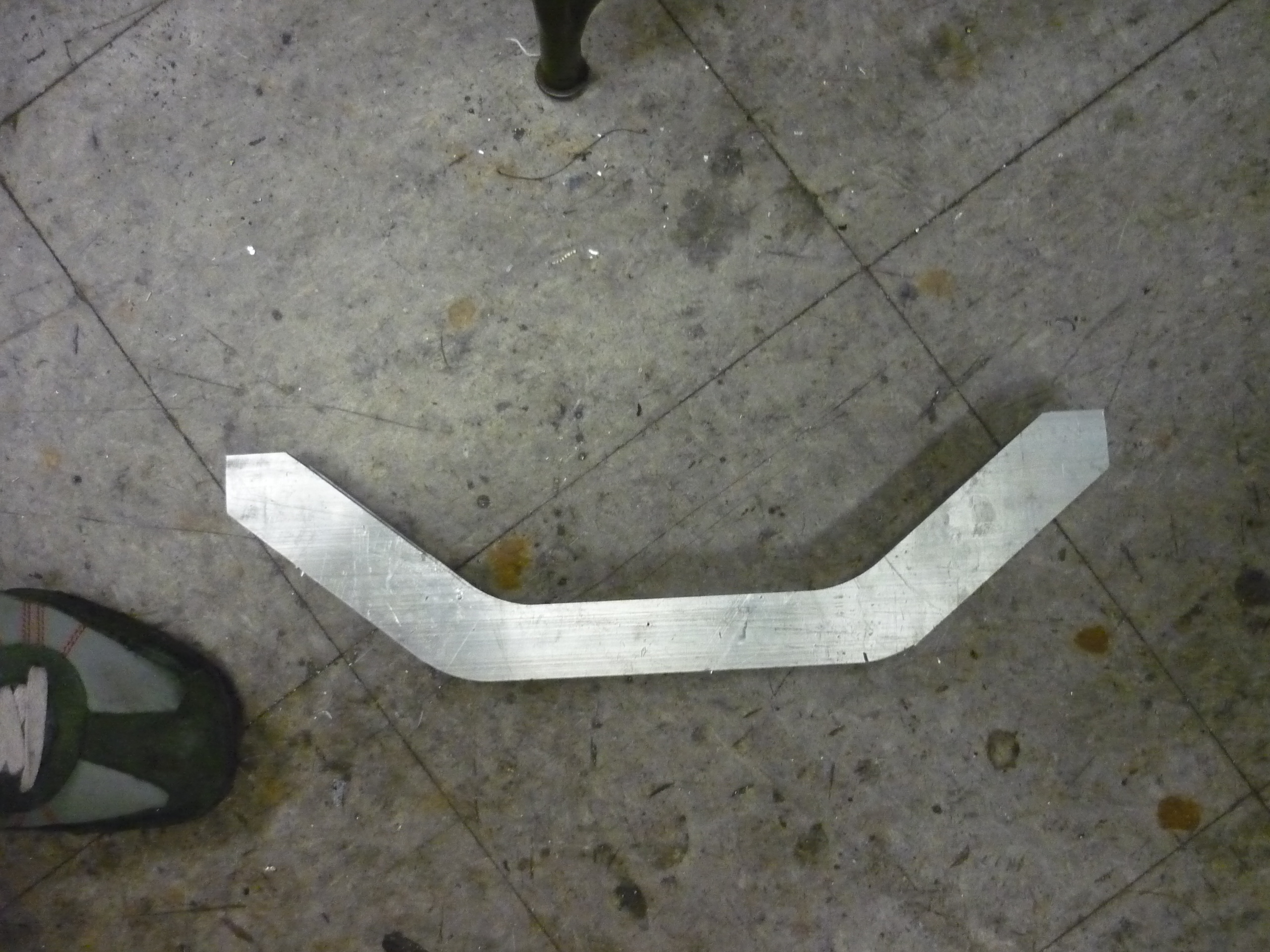
| New
Swing arm ahoy The advantage of the two part setup allows for cables to be run through the inside of the frame assembly, and not appear outside. This does require some extensive milling, which is covered below. |
 |
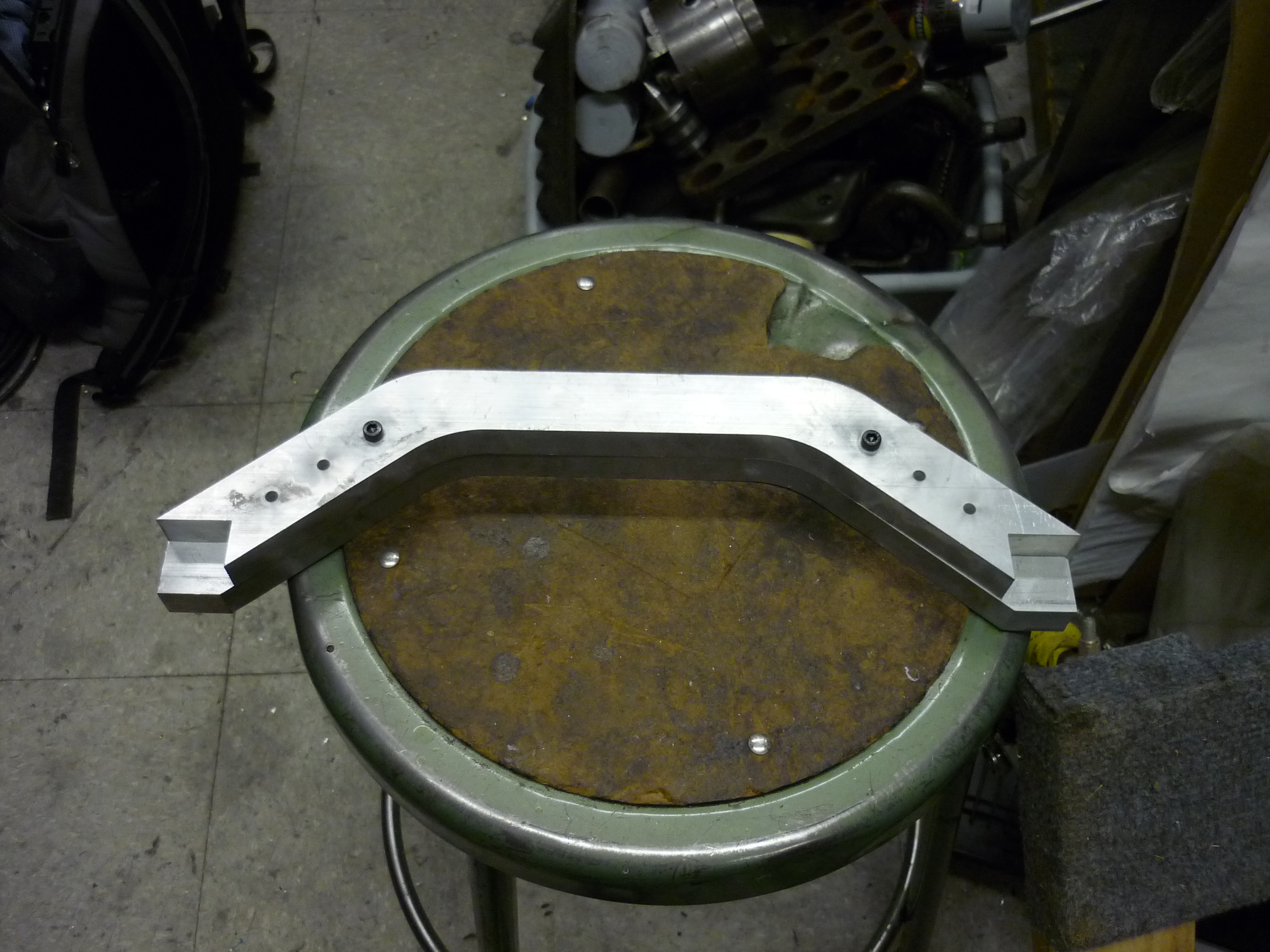 |
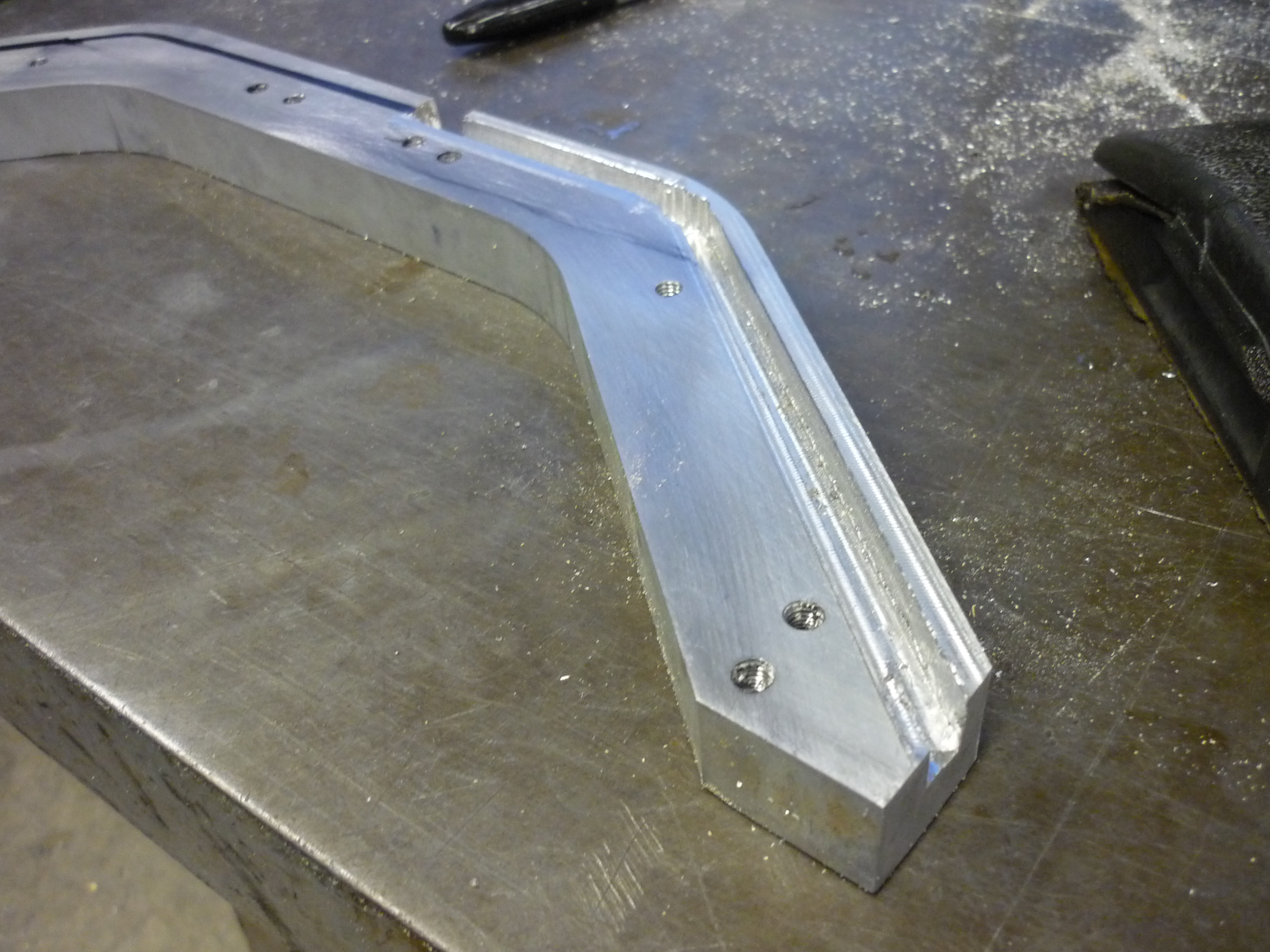
| Mounting the new swing-arm before / after. The measurement for the gap and the indent worked out well. The new swing arm looks much smoother in that slot! |  |
 |
| I took advantage of the water jet to pre-space holes for drilling and tapping in the screws that hold together the two parts of the swing arm. These are attached with M4 screws. |  |
 |
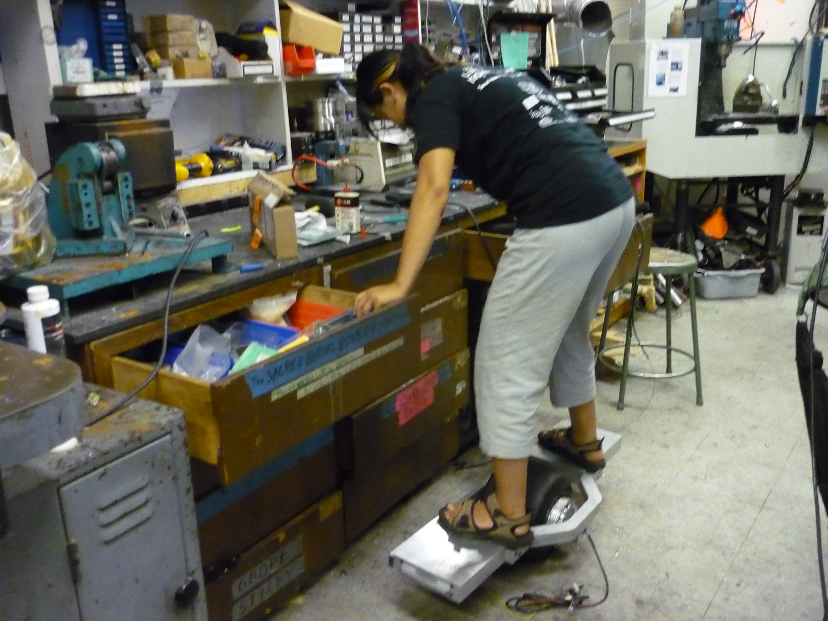
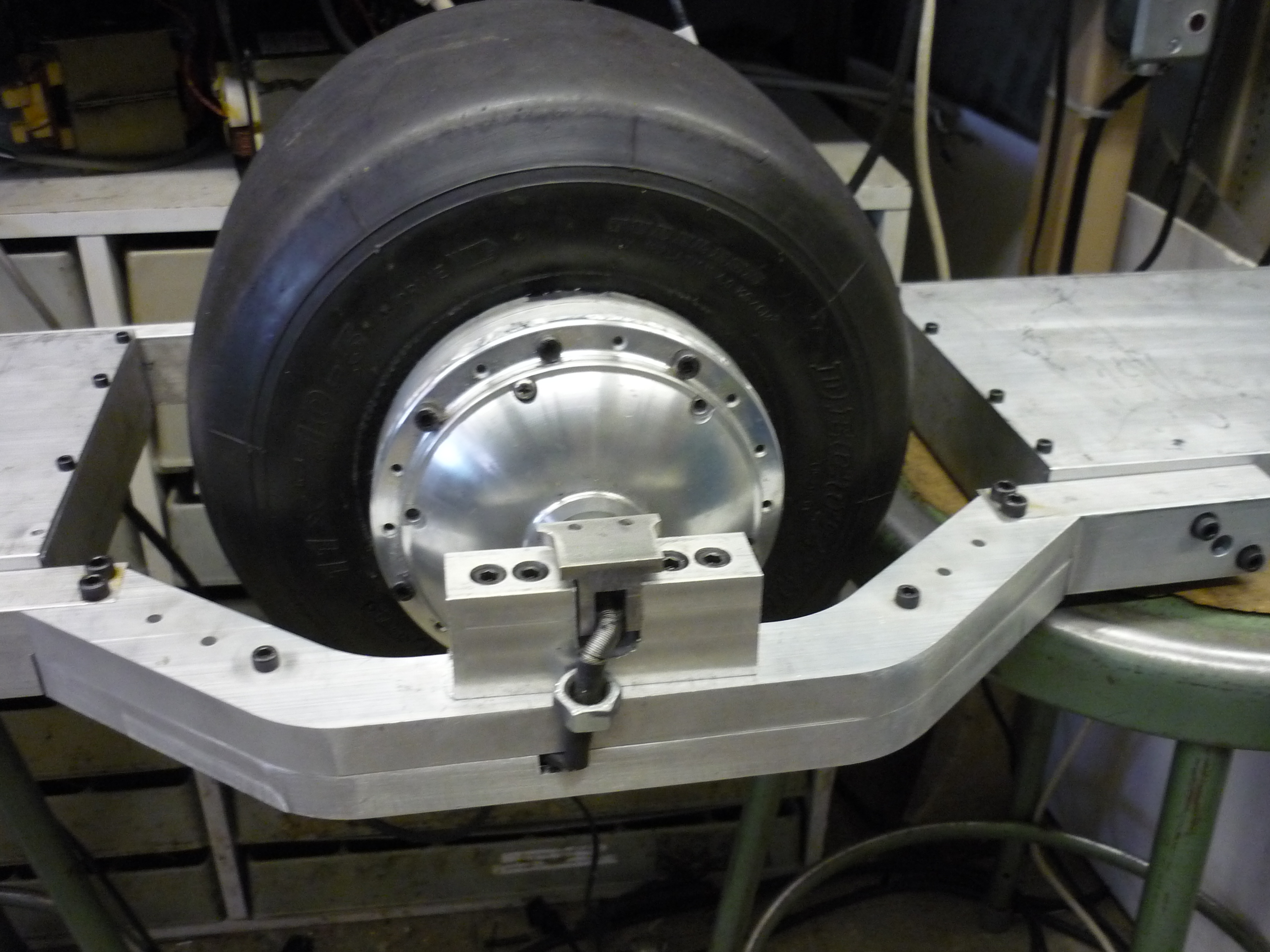
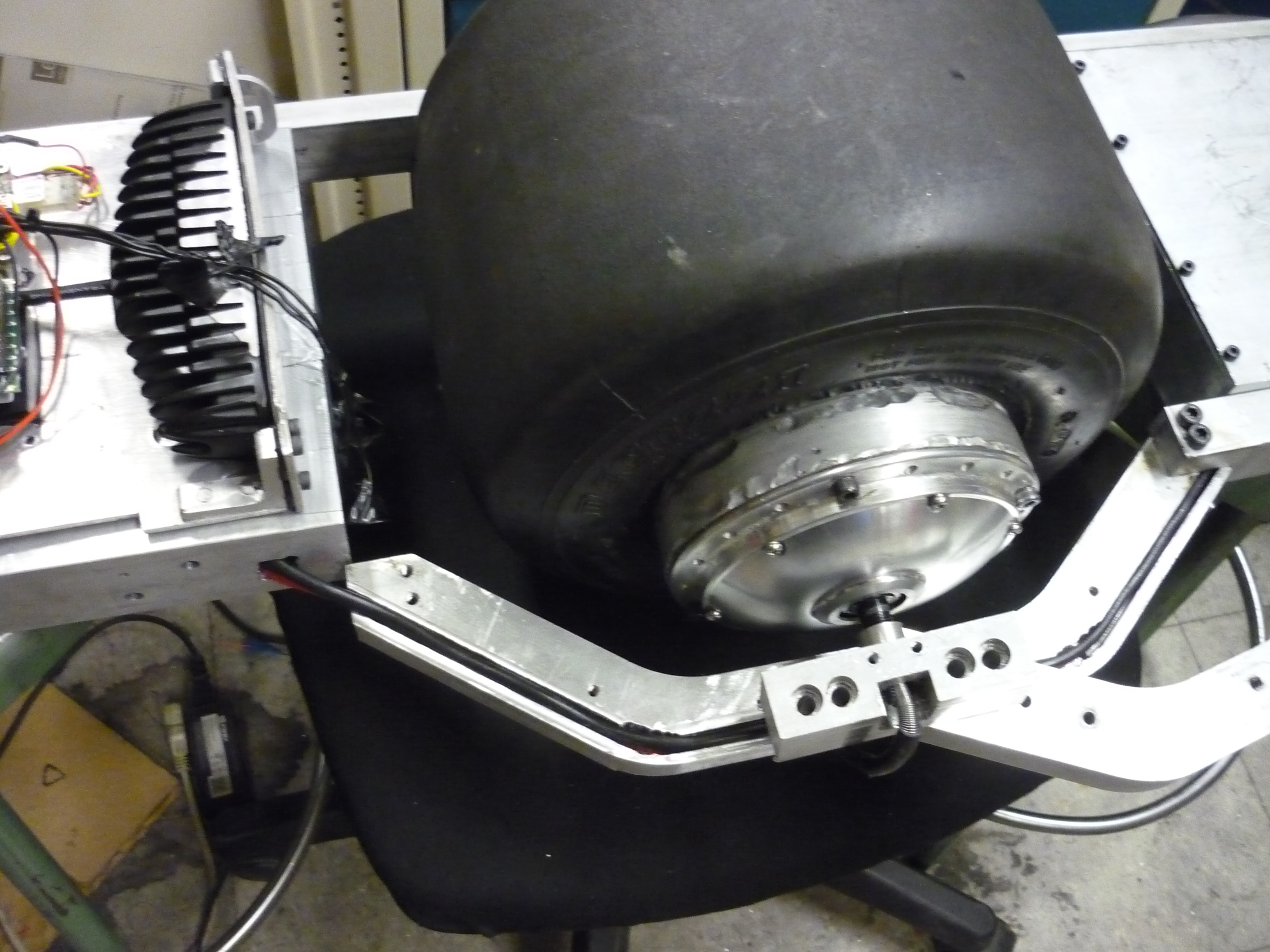
| With the opposing brace and new swing arm installed the skateboard was ready for load-testing! A Nancy O' balanced between two shelves. It looks like it just might work! The clearance to ground was pretty good, the swingarm did not appear to flex and the motor mounts looked solid. |  |
 |
| A-M-C Motion Control Corp to the rescue. |
| The day things
swtched to awesome I had been concerned about the 'littleton poly-sci' controller sporadically faulting/overheating. While keeping it cool seemed to work for the most part, having the motor drive sporadically enter 'fault' mode and stop working was SUBOPTIMAL. I contacted A-M-C and explained my project and an interest in one of their servo drives. They were extrodinarily helpful. They equally wanted to see this contraption zoom about, and after taking a look at some preliminary construction photos, AMC gifted me a drive to use. Not just any drive, a AZB60A8. YOWZA! |
 |
| Myself and Build-its-Ben had been eye'ing
some of the really really
nice servo drives that A-M-C produces for
a while. Have you seen Ben's robot arm? AMC's drives
come in a variety of flavors and sizes, a few of
which were almost to-good-to-be-true for the
skateboard project. <photo credit Ben> |
 |
 |
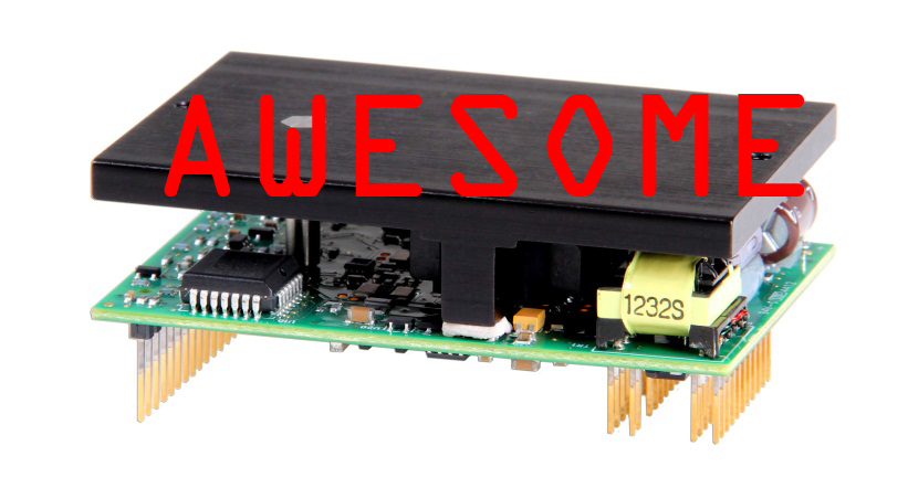
| Let me take a moment here and describe how much
awesome this servo drive has inside. *60A peak, up to 80v *Four Quadrant Drive (REGEN!) *Mounts right to a PCB *Tiny! 2"x3" x 1.325" |
 |
 |
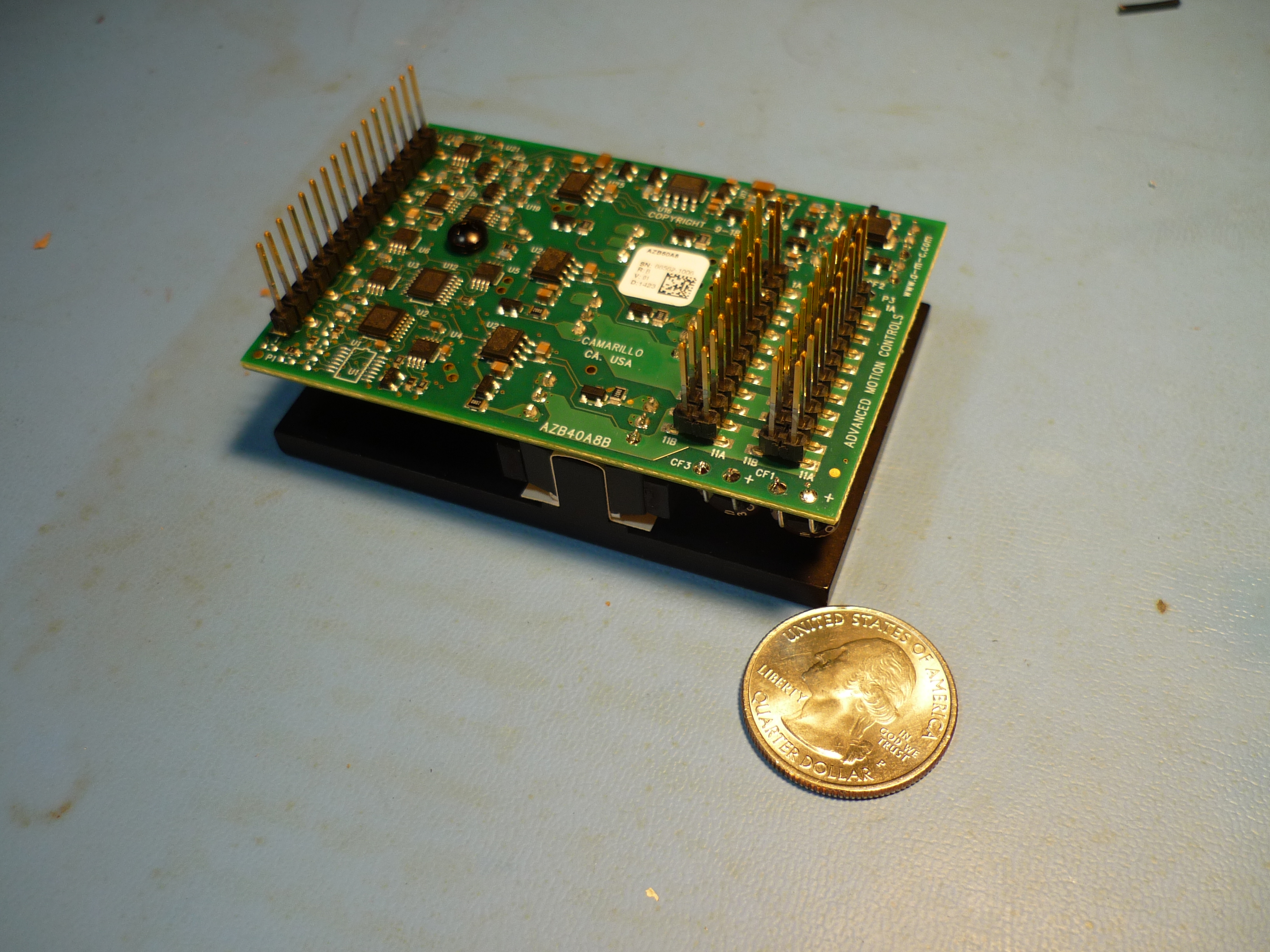
| A GLORIOUS DAY The box arrives! Inside the AZB60A8 hid amongst packaging material. AMC was also kind enough to send along some nifty decals and stickers! |
 |
 |
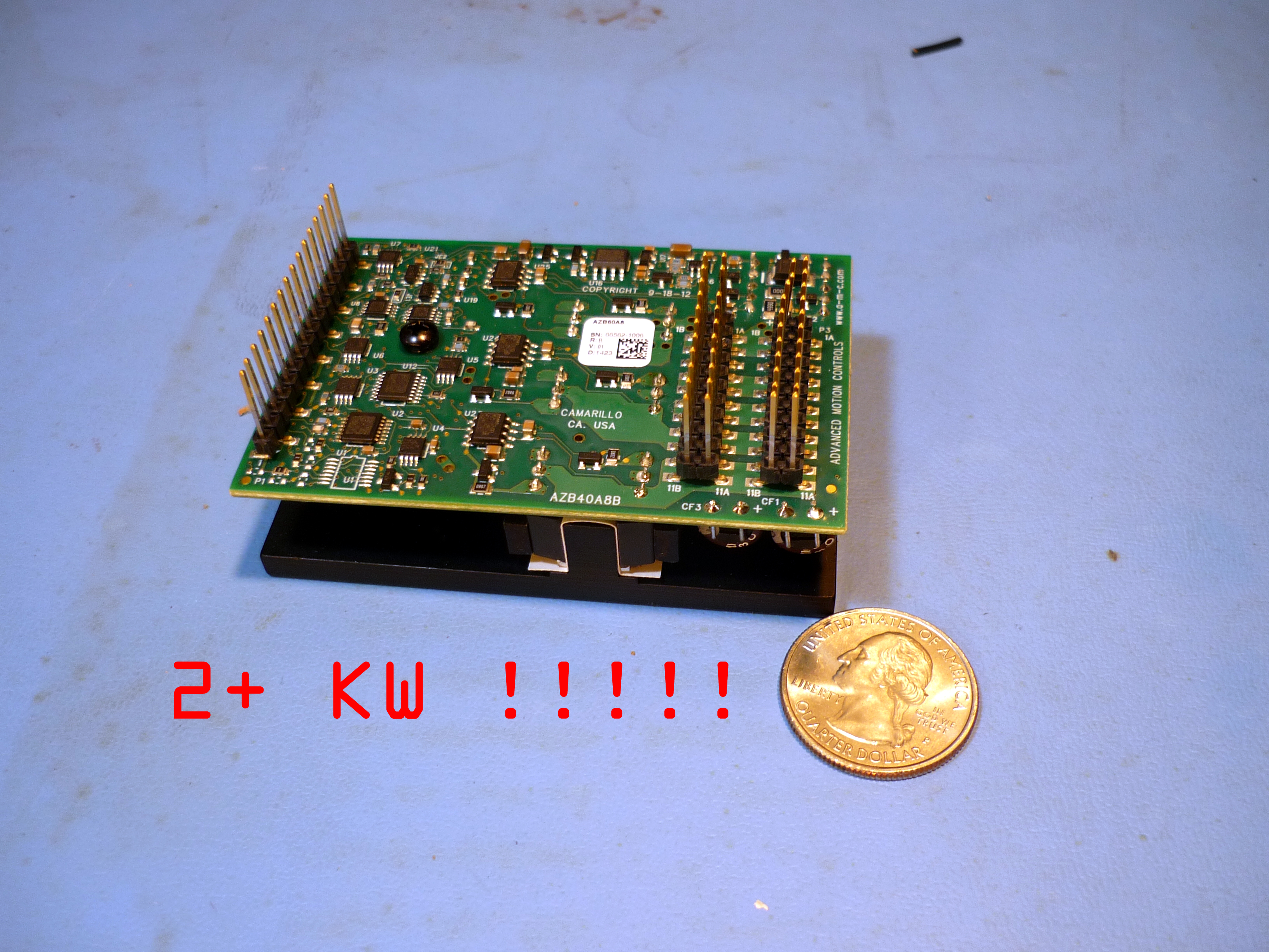
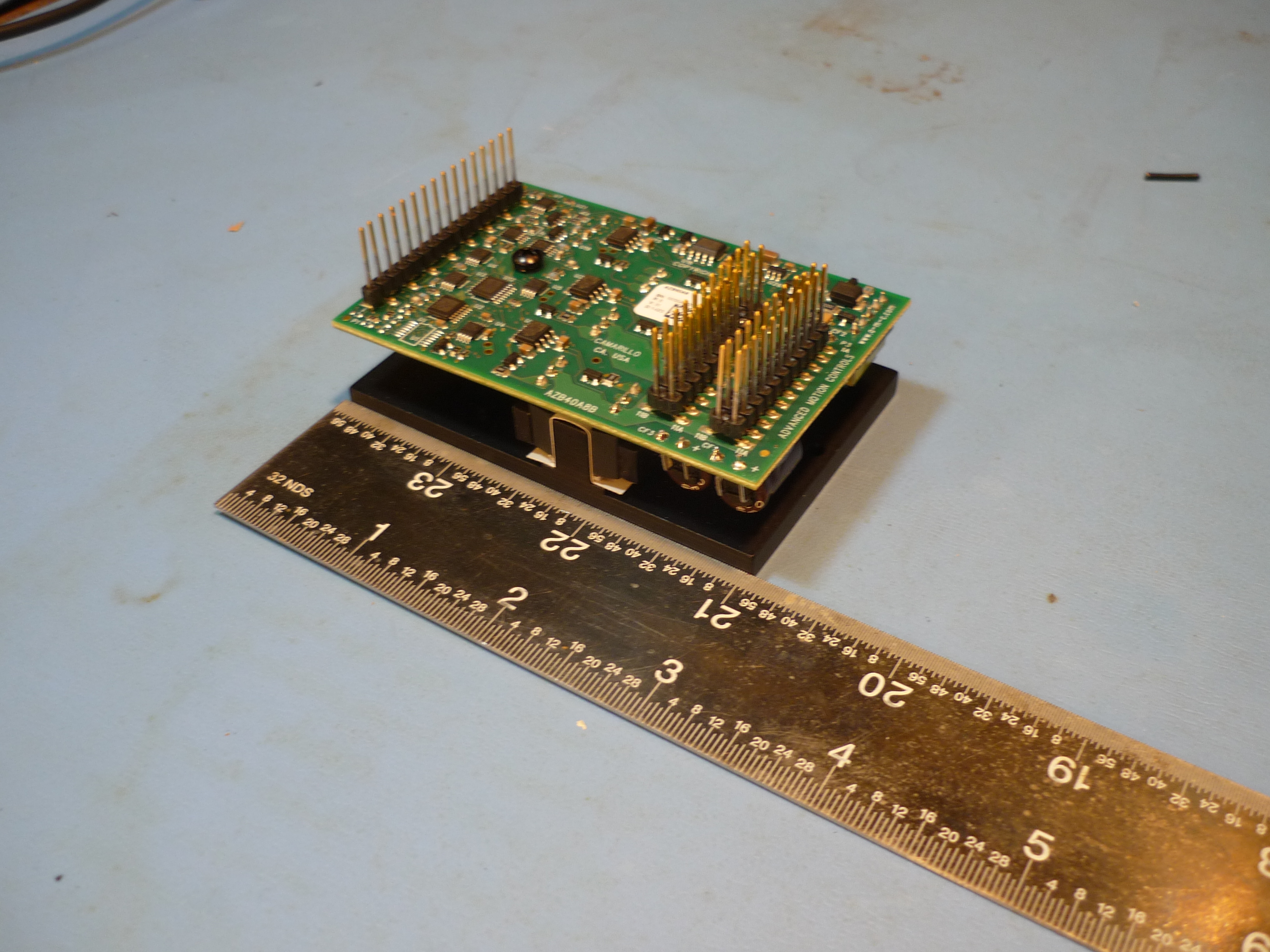
| Incredibly
power dense The drive is physically tiny, yet capable of 2kw peak! Shown (right) is the drive next to a US quater for scale. The three phase feeds and power lines are routed over parallel headers, which is an interesting choice for a connector. The connectors are much longer than standard 100 mil spaced header, and i'd imagine this is specifically to address increased current handling, by increasing surface area. AMC lists in their data sheet the mating part numbers (Samtec: BCS-116-L-S-PE) and (Samtec: SSM-111-L-DV), which was useful for quickly designing a carrier board. |
 |
 |
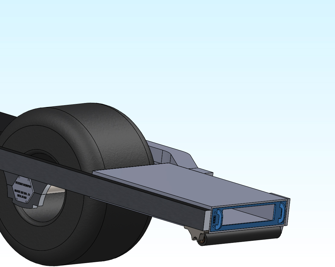
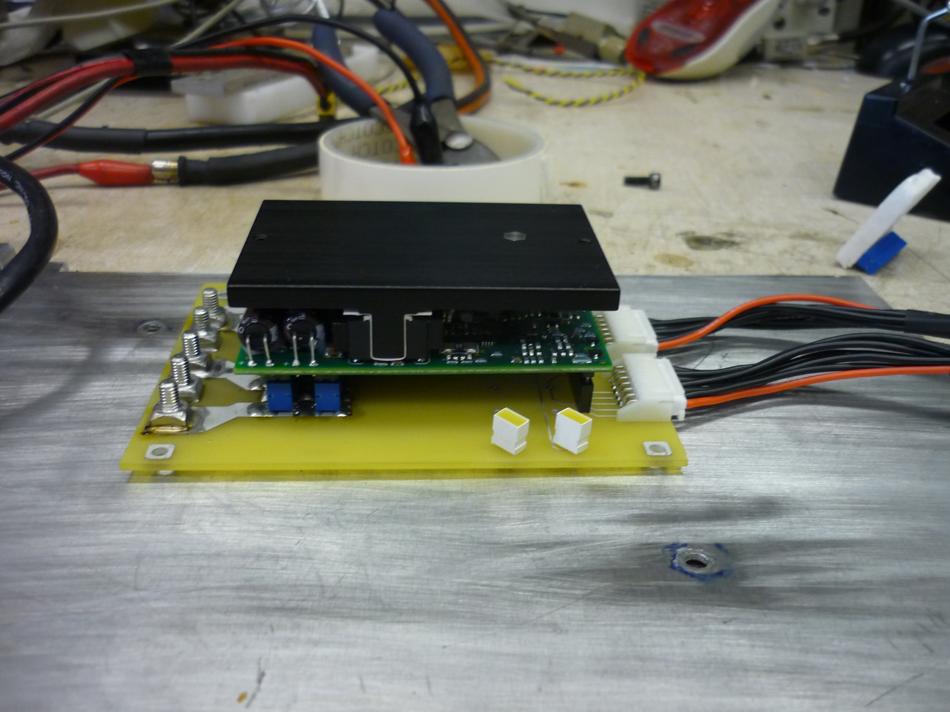
| Design ideas I spoke on the phone with an engineer from AMC and he provided a bunch of useful feedback, namely to keep in mind that the drive is four-quadrant. A four-quadrant servo drive effectively 'regens' into its supply when put under a reversed load. A number of power supplies have no idea what to do with this and enter a fault mode. Fortunately batteries will graciously accept regen current. We also spoke about mounting and heat sinking, namely that using the giant aluminum frame as a heat sink should work well. Shown (right) is the motor controller mounted to a homegrown carrier board and the assembly sitting atop the aluminum motor controller skid. The phone feedback was incredibly helpful! |
 |
 |
| Controls and Power |
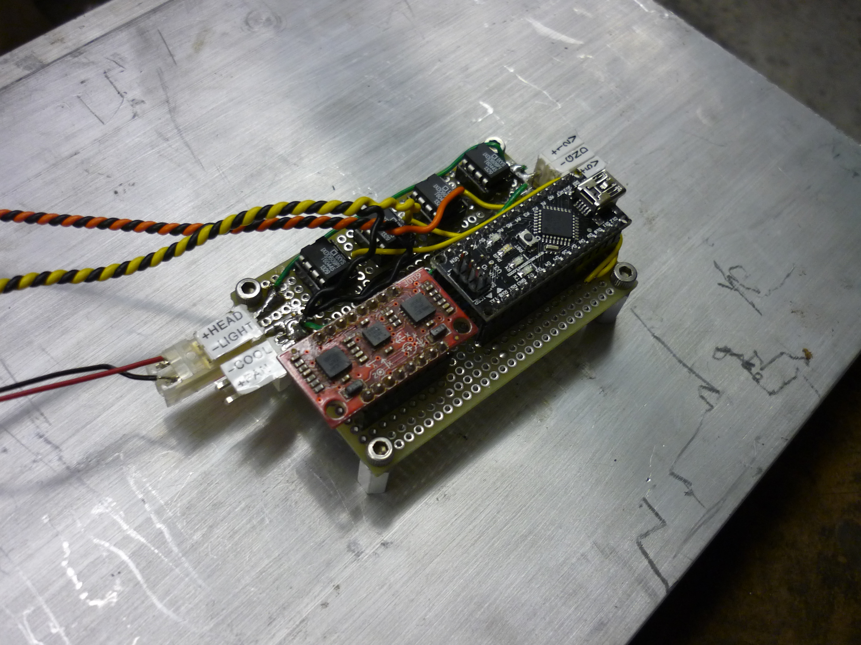
| To expedite getting the servo drive up and running, I used a tiny atmel atmega328 dev board (arduino mini) working alongside an analog IMU board mounted on a perf-board. This IMU was the exact same one used in segboard, found by Ben during the miters-spring-cleanup. Initially I had purchased an I2C interfaced gyro + accelerometer, but the overhead for the communications was fairly substantial, versus the 'connect directly to an ADC port and simply read the ADC. Four IXYS fet-drivers are used to act as level converters for the analog input lines for the servo drive, as well as the switched 12v for the headlight and fans. | 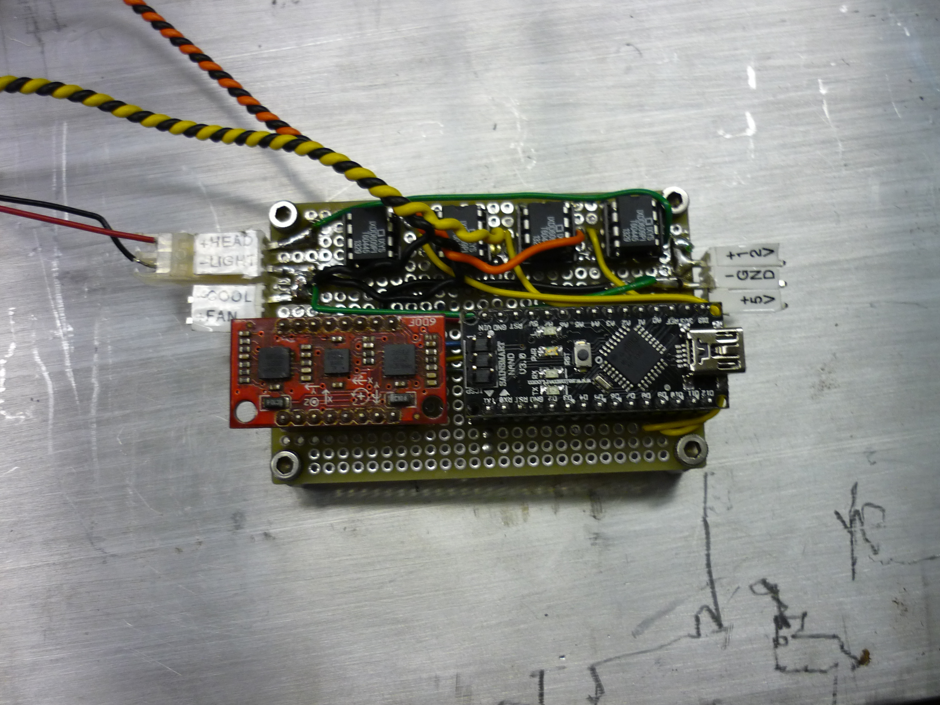 |
 |
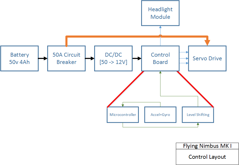
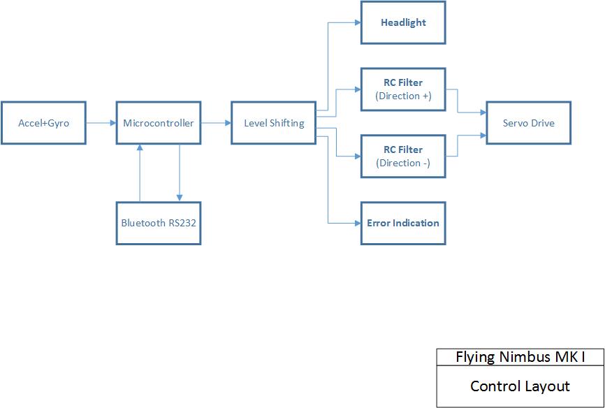
| Layout: The basic layout displays power and signal distribution, and the controls layout displays the basic: [visio] controls: [visio] |
 |
 |
| DC/DC converter To bring down the pack voltage to something useful, I snagged one of these beauties from the ever awesome Charles guan. When the pack voltage is present, the dc/dc drops down the input to 12v at a reasonable efficiency. The 5v logic rail is fairly low power (~20 ma) so a little 7508 linear regulator run from the 12v line was used. The hall effect power is also supplied from a 7805 regulator. |
 |
 |
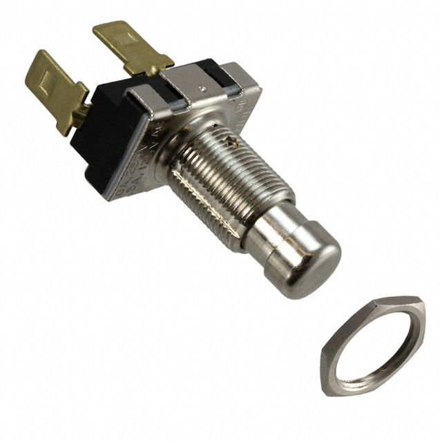
| Deadmans switch For the deadmans switch I opted for an IP67 sealed 'stomp-able' switch, which was unfortunately pricey [Digikey PN: 451-1199-ND]. I've run into a number of pushbutton temporary switches which fail early when faced with any non-vertical loading. In this case, the skateboard would most definatley get slammed from every direction. This part failed after a few days use and was replaced by an ebay guitar-stomp-button. (shown far right) |
 |
|
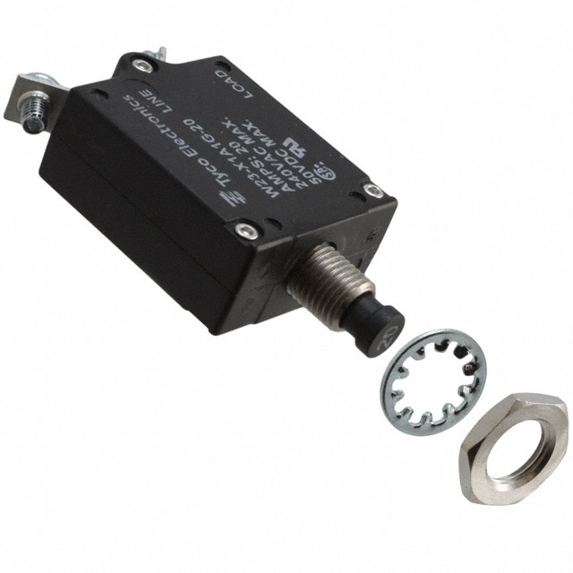
| Circuit
Breaker A fuse, or system disconnect should be located as close to the battery as possible. If a short in the line between the battery and the motor controller occurred, this will interrupt the power to the system. [Digikey PN: PB411-ND]. Locating the breaker as close as possible to the battery is helpful in preventing issues down the power path from being catastrophic. |
 |
 |
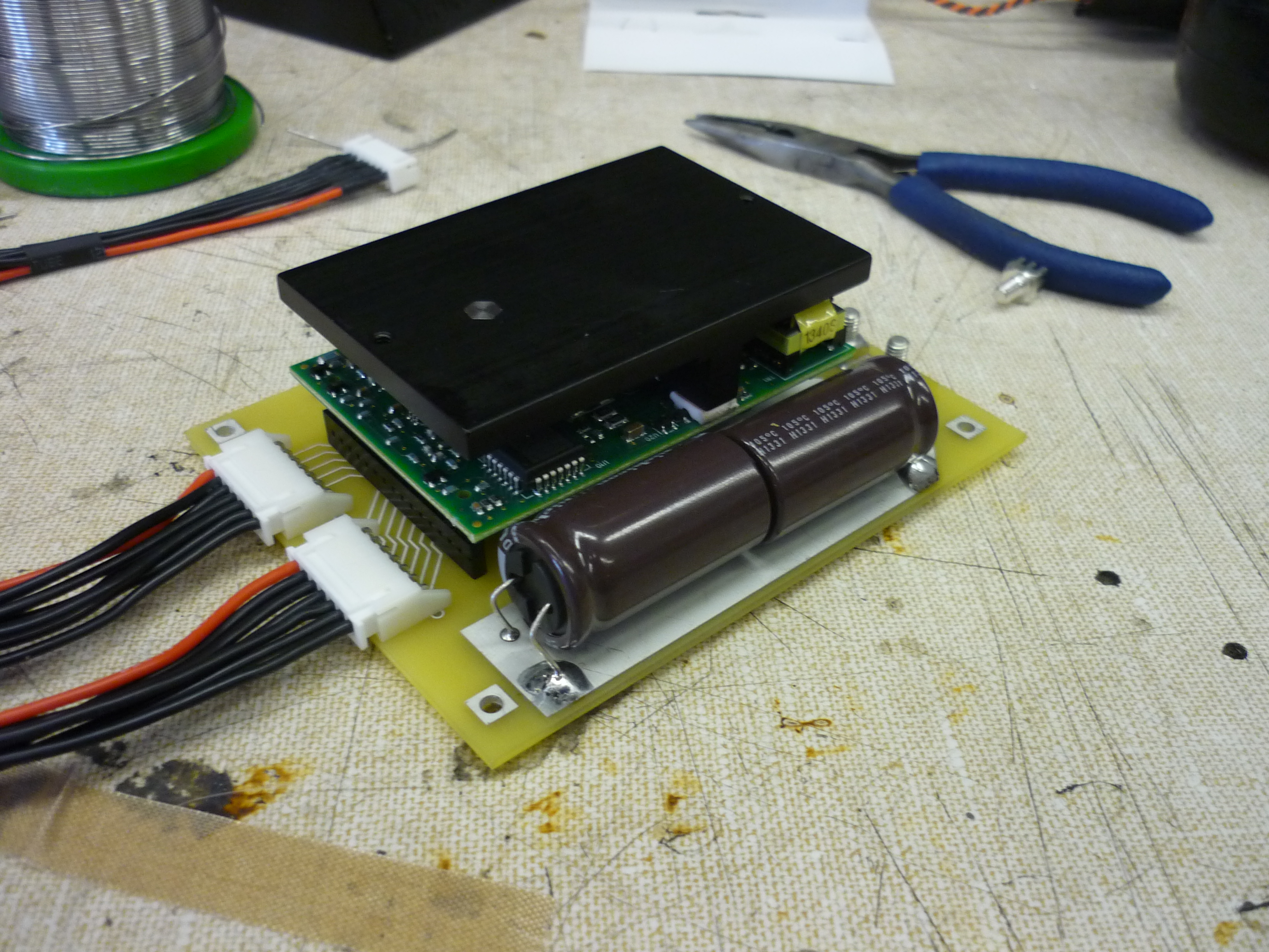
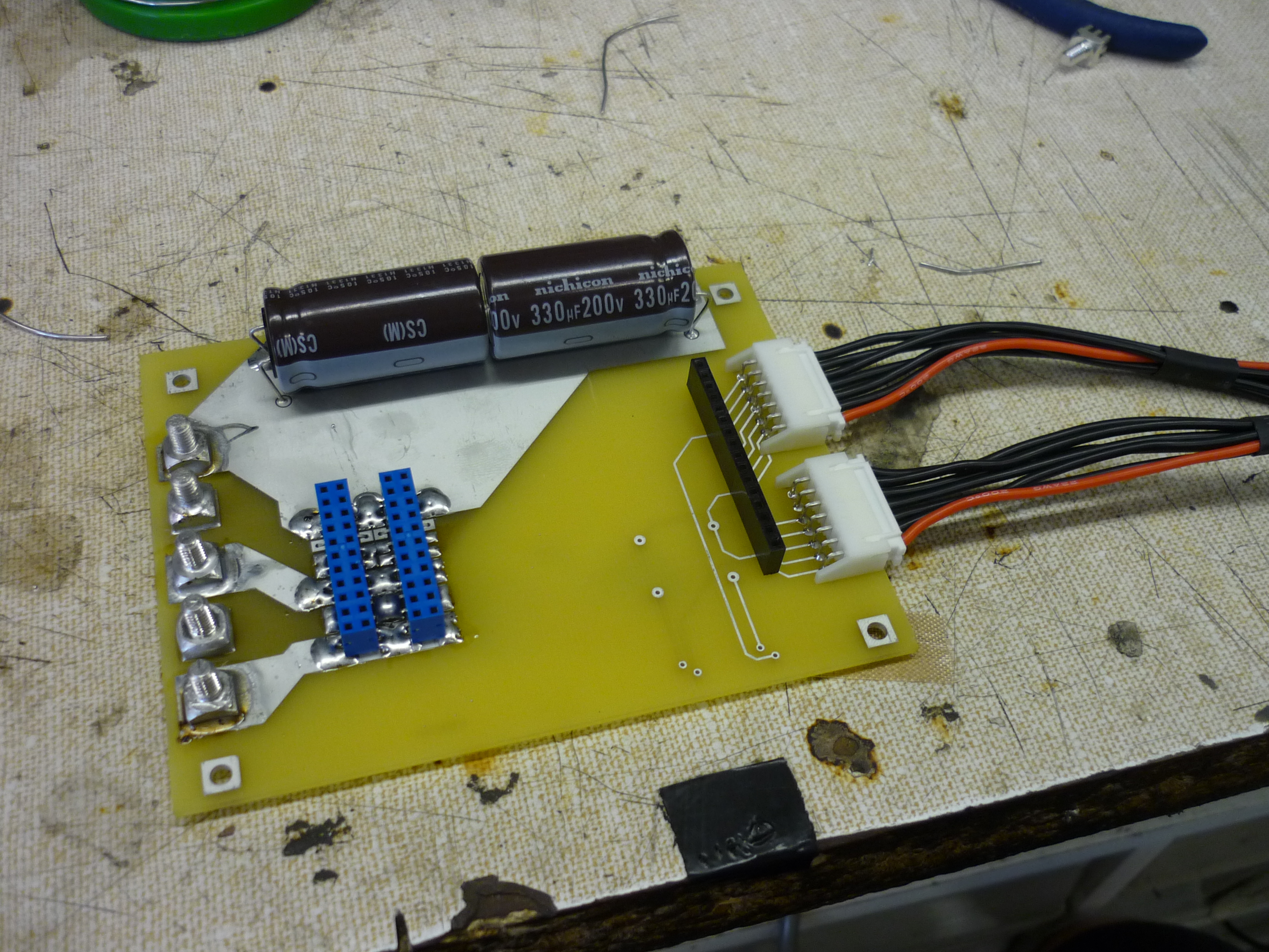
| Motor
control holster Following AMC's data sheet, I put together a holster for the motor drive, featuring 660 micro farads of bus-capacitance, external cabling to connect to the drives signaling inputs / outputs and my favorite, giant Wurth solder-in lugs for the power & phase connections. The whole assembly sits upside down with the motor controller mounted to the skateboard frame (as a heat sink). Thick isolating rubber was used to prevent the board from shorting out on the aluminum frame. |
 |
|
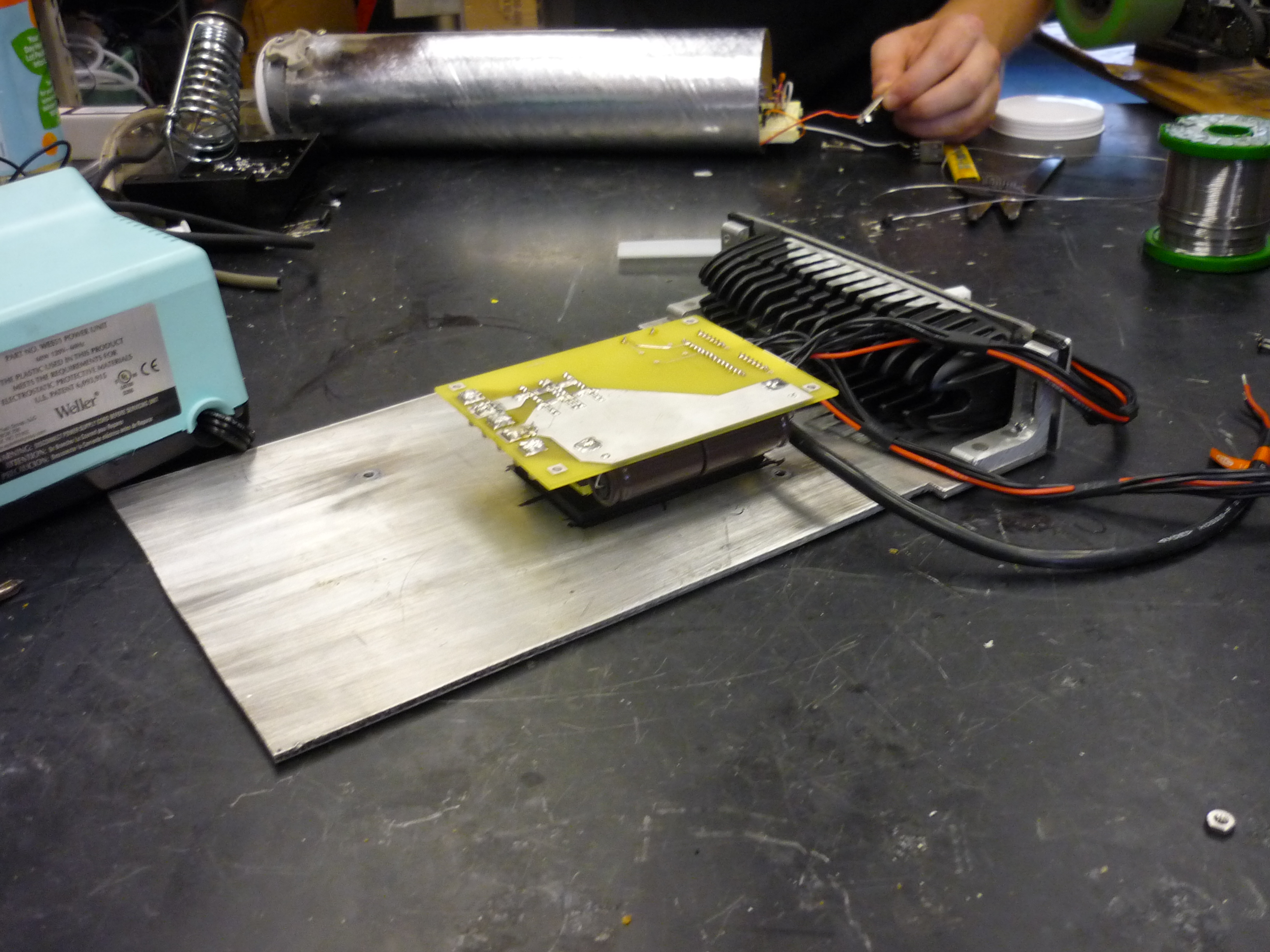
| Glamor
shots As this was a quick board, (without soldermask), it needs buffering / isolation from the nearby metal frame as well as any stray wires. A layer of insulating foam will be applied to the board to prevent / mitigate any wayward shorting. |
 |
|
| Bluetooth The control microcontroller (arduino nano) is reprogrammable over rs232. To make it easier to change controls constants, I added a cheap [link] rs232 bluetooth bridge board. More info below |
 |
 |
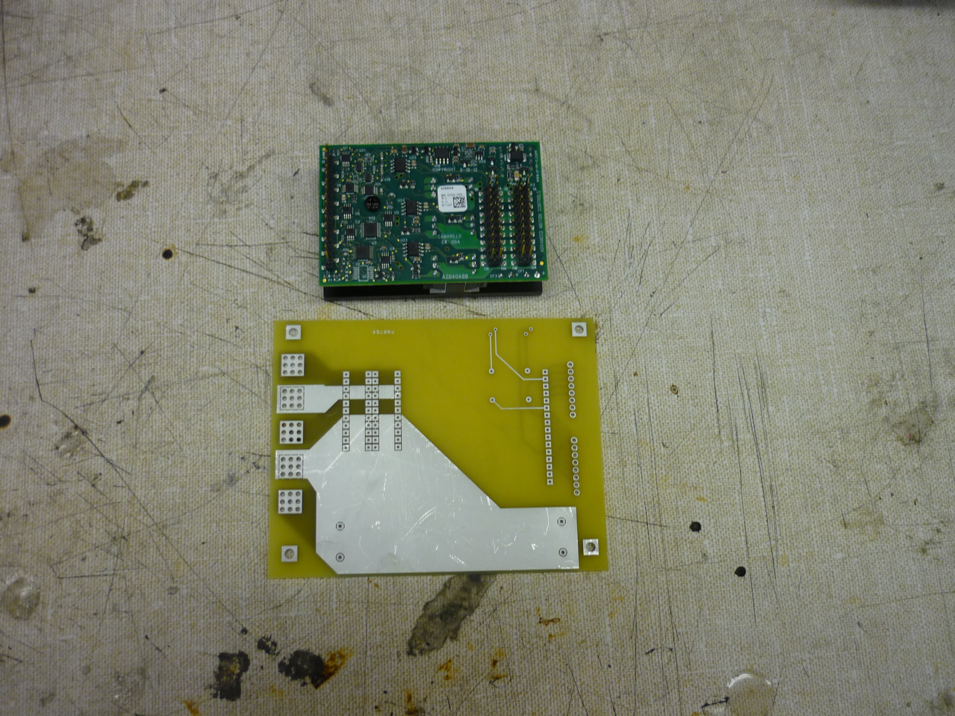
| Design
Files The breakout board adds the required external bus capacitance and pins out the error led as well as the 3phase motor outputs and the dc bus inputs. Advanced Circuits Barebones service was used to make a quick breakout board. Design files for the pcb are available here: [freepcb] [gerbers] [top copper] [bottom copper] |
 |
 |
| The first test of the AMC AZB60A8 Drive! |
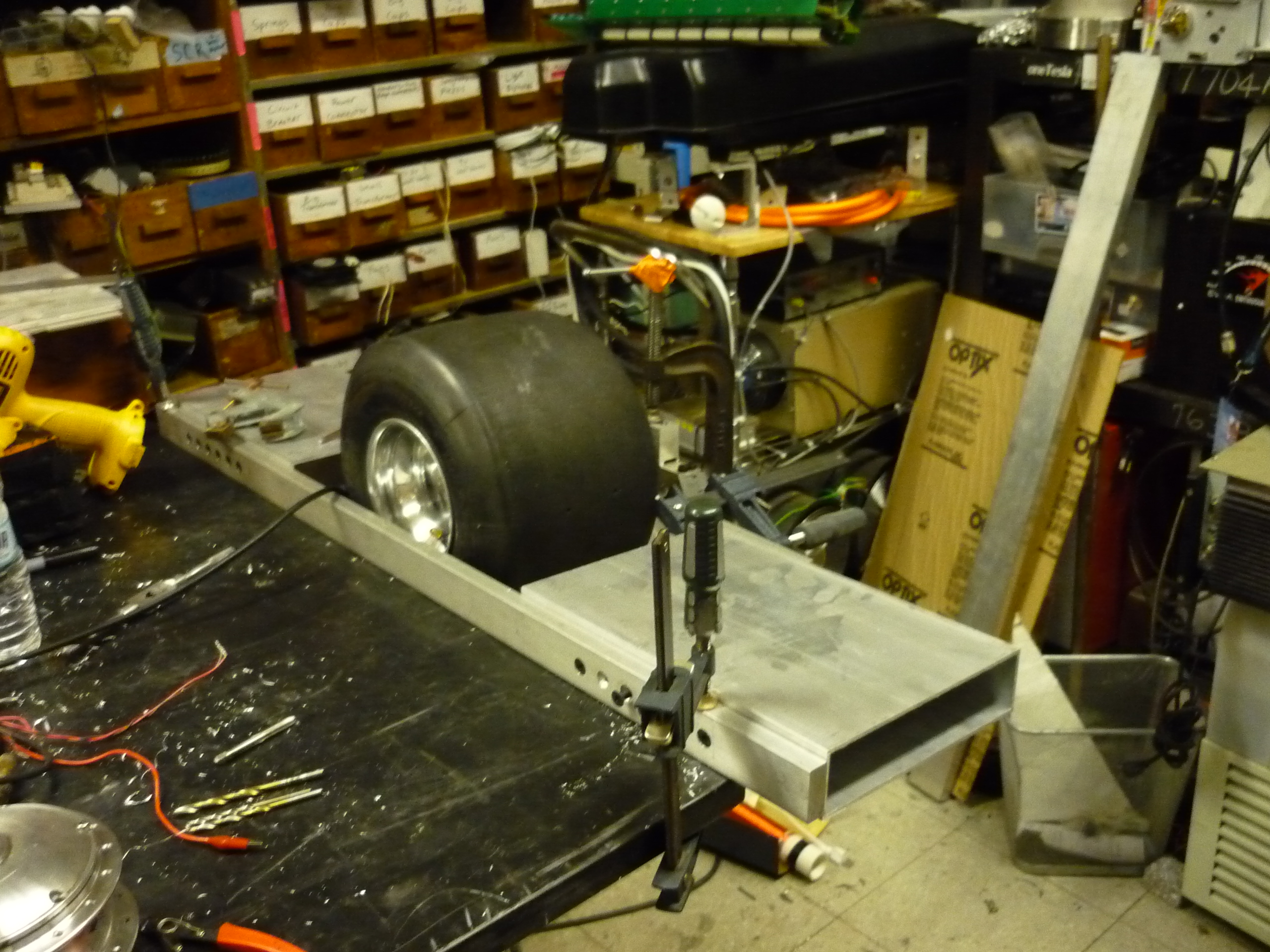
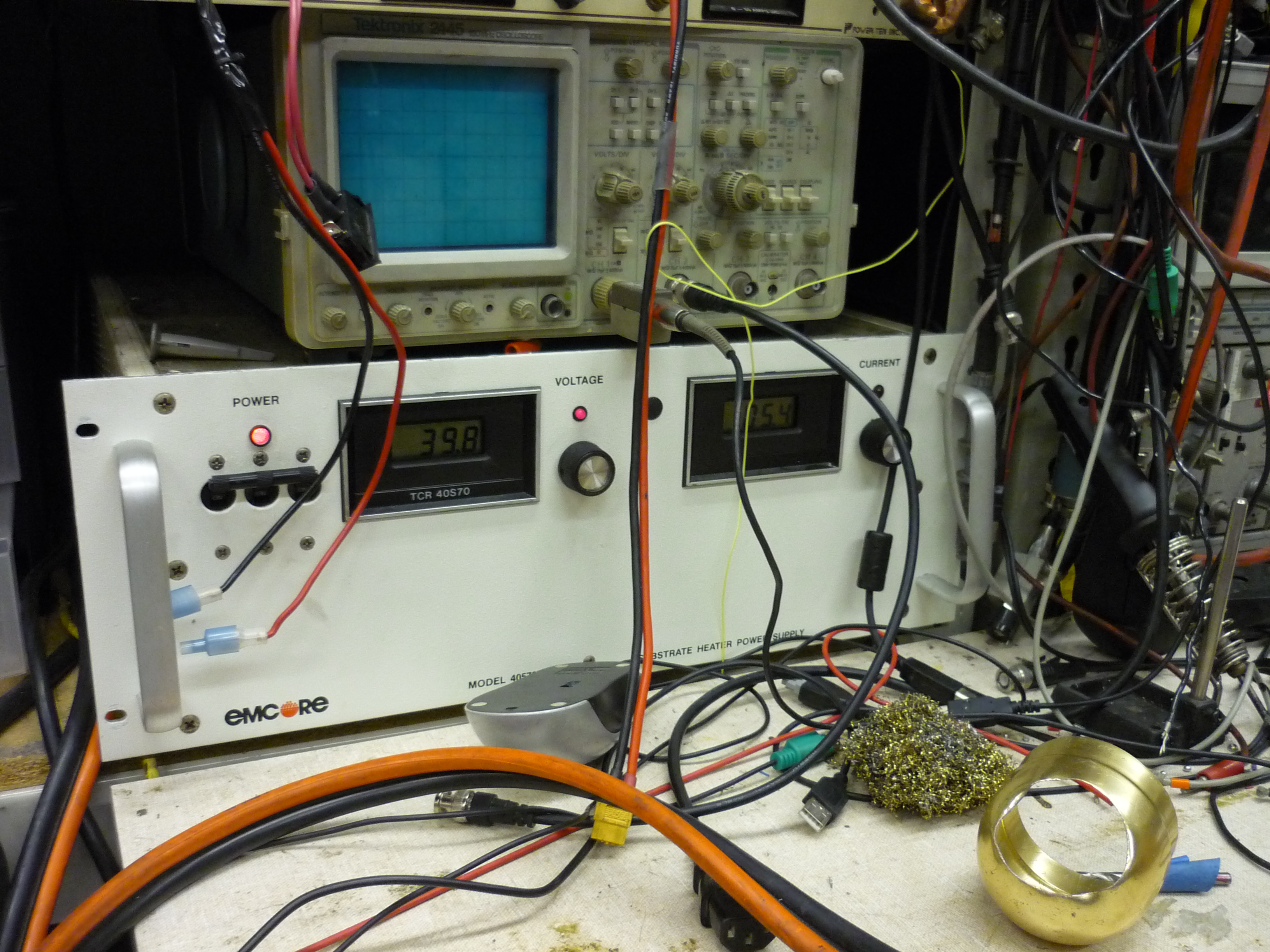
| Everything ended up working fairly swimmingly after wire routing.The skateboard contraption is sitting on rolling chair handles and the rate-gyro platform is bolted to the motor-controller carrier plate. The setup is powered by a 5A 40V supply. In this instance drive-inhibit is used to power down the motor before unplugging. |
| Updated Motor Control + Lighting Platform |
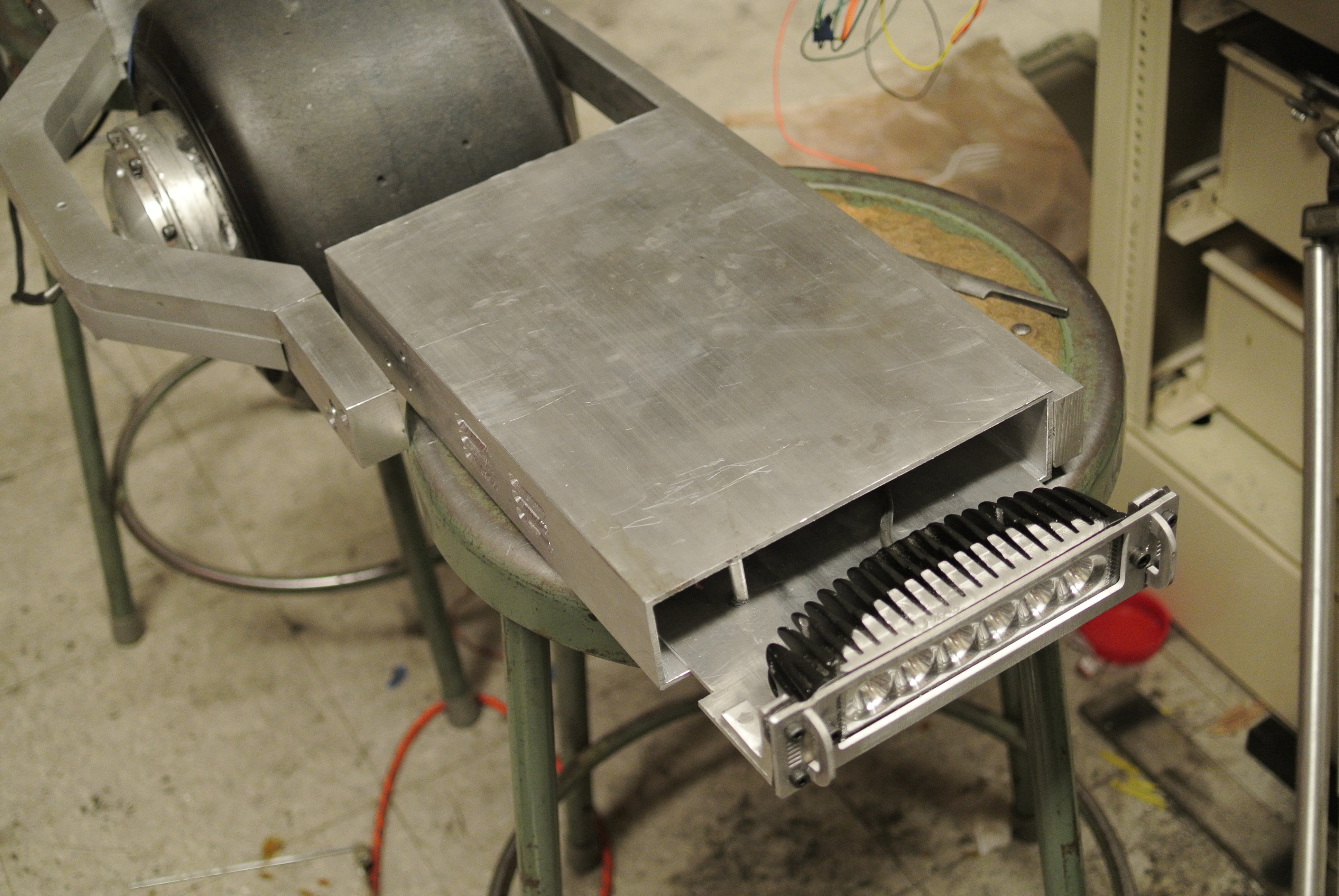
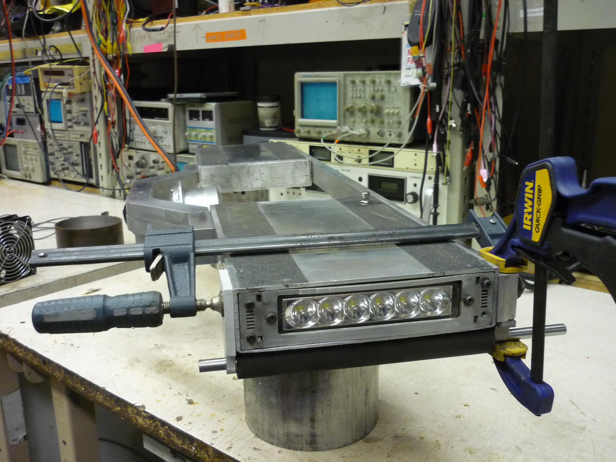
| The rough placement for the motor controller, front facing headlight and latching mechanism needed some re-work, so I re-designed it to match the battery-holster setup described below. This uses 1/8" thick 6061 plate. |  |
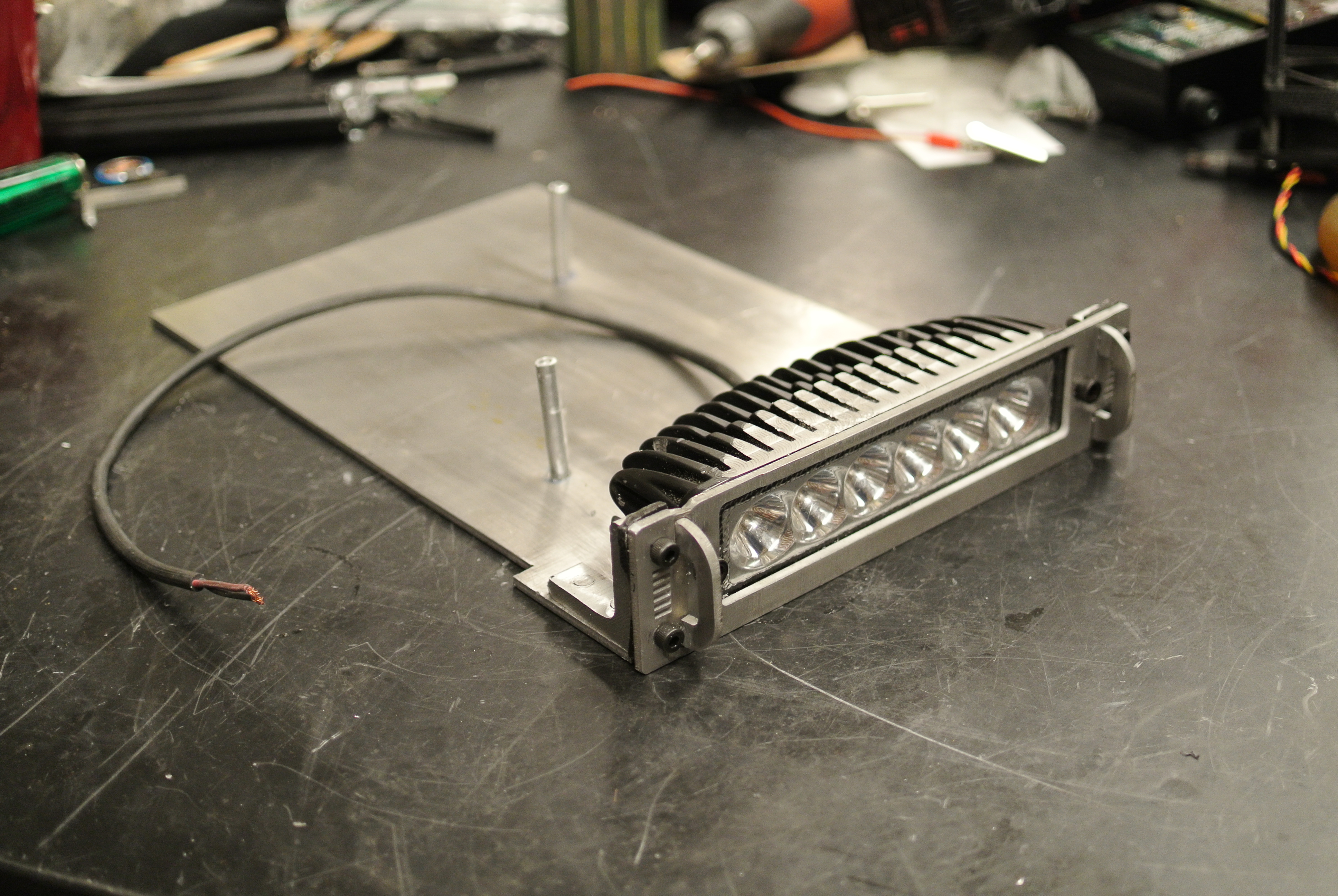 |
| Water jetting extra handles and front-ends The hobbyshop (link) has a beautiful water jet, and it made quick work of cutting 1/8" thick 6061 plate. I had thrown together the design for the plate earlier the same afternoon, and managed to squeeze in 30 minutes of water jet time the same day. Fortunately it wasnt a crowded Friday. The plate used was actually scrap plate from the first atomic-bumble battlebot. |
 |
 |
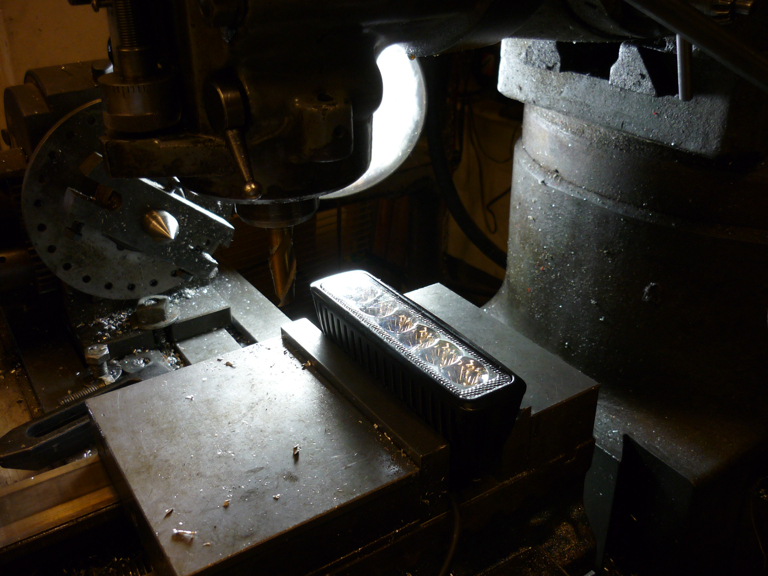
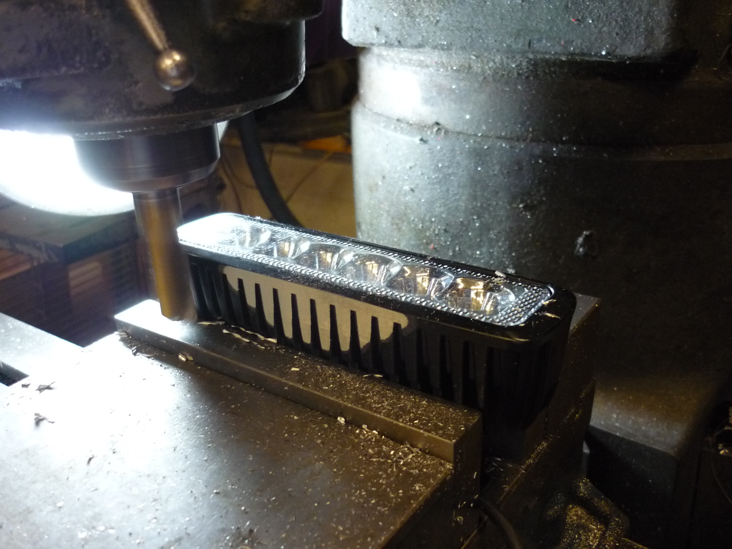
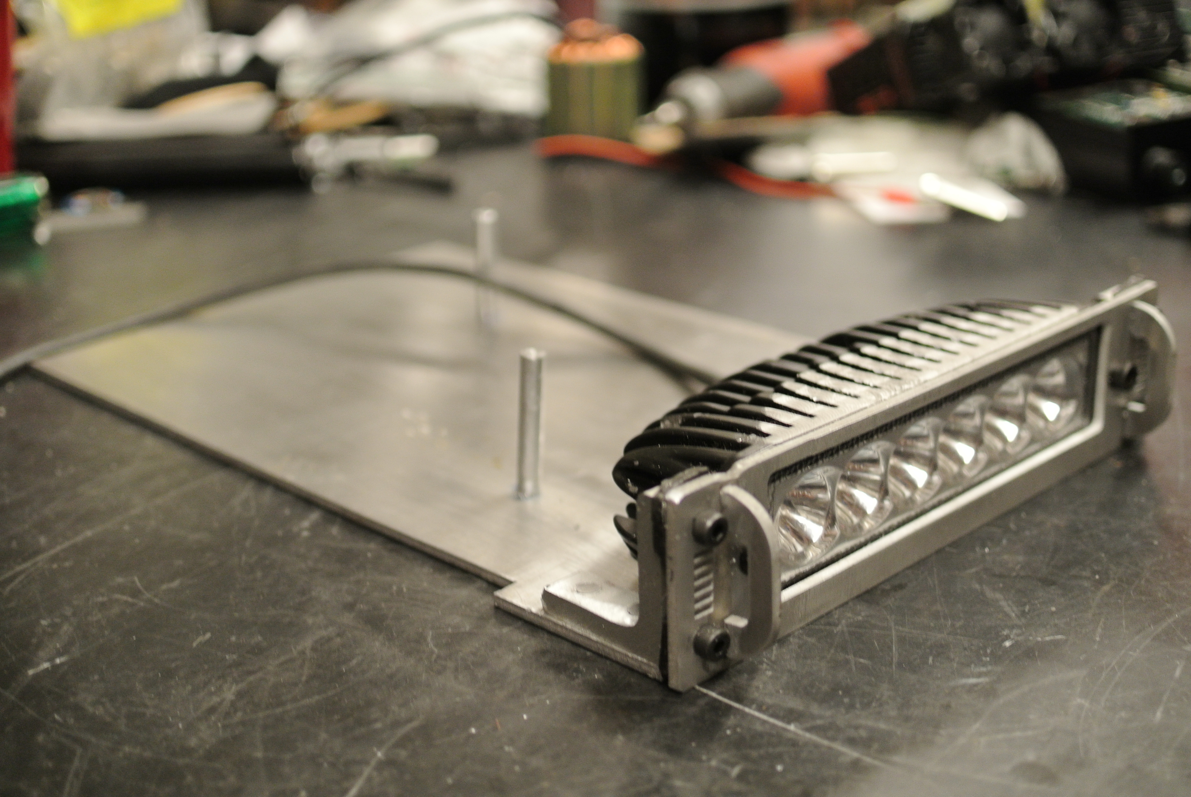
| Milling
down... An LED So it turns out the led module I purchased (link) was a bit too tall / curvy to fit inside the skateboard cavity. The outside of the module is all cast-aluminum, but without knowing how much casing was there, or if it was hollow, I took it slow, carving out roughly 1/8 of an inch from the top and bottom, using a Bridgeport mill. With the new, flat, reference surface, it became quite a bit easier to mount the lamp later-on. |
 |
 |
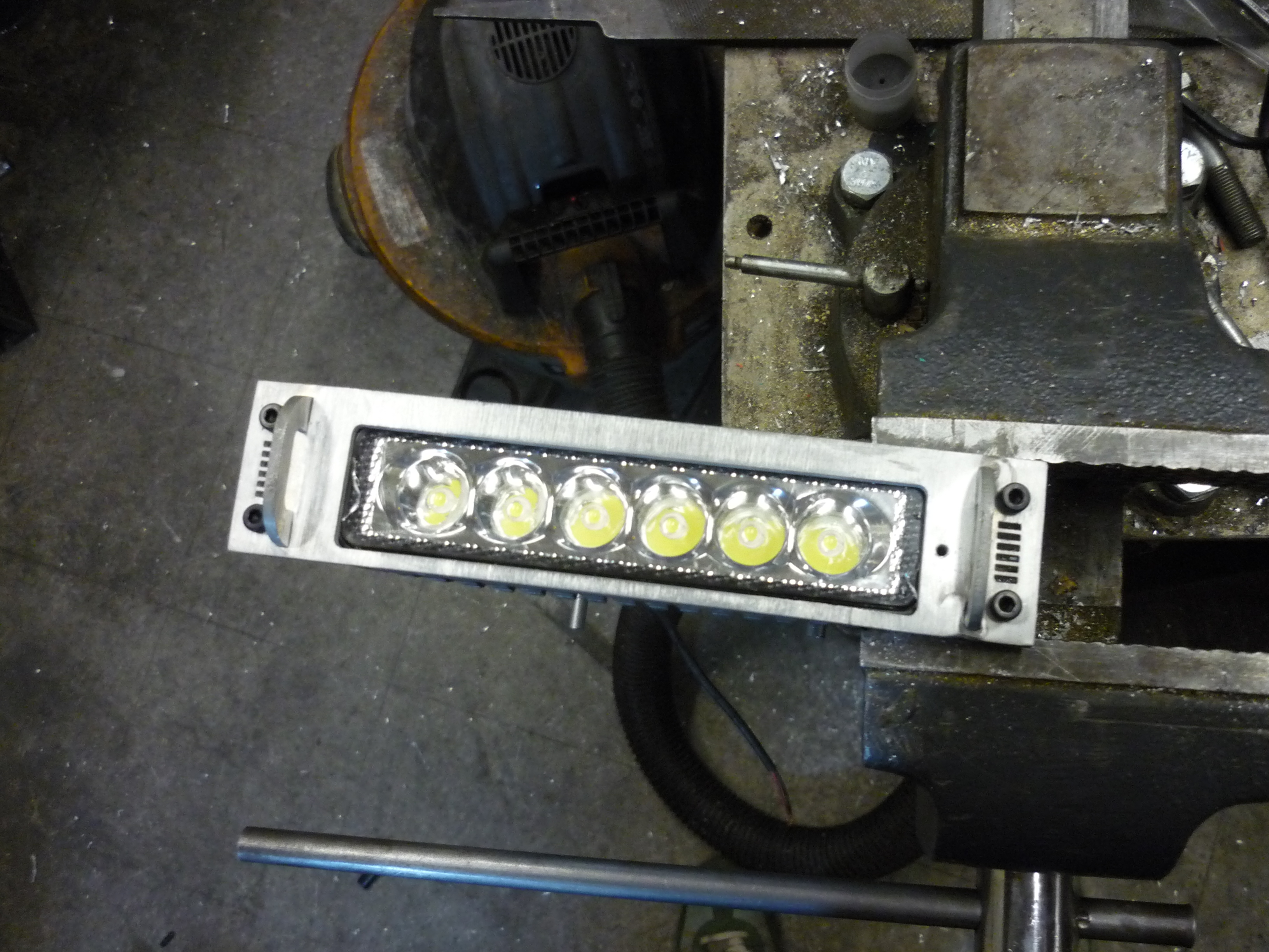
| Water jet parts came out amazing. The front plate (cad shown above), fit together well, with the integrated handles tig-welded on the back-side. To make for a cleaner-mate between the front facing headlight and the casing, I opted to tap directly into the led aluminum heat sink extrusion. |
 |
 |
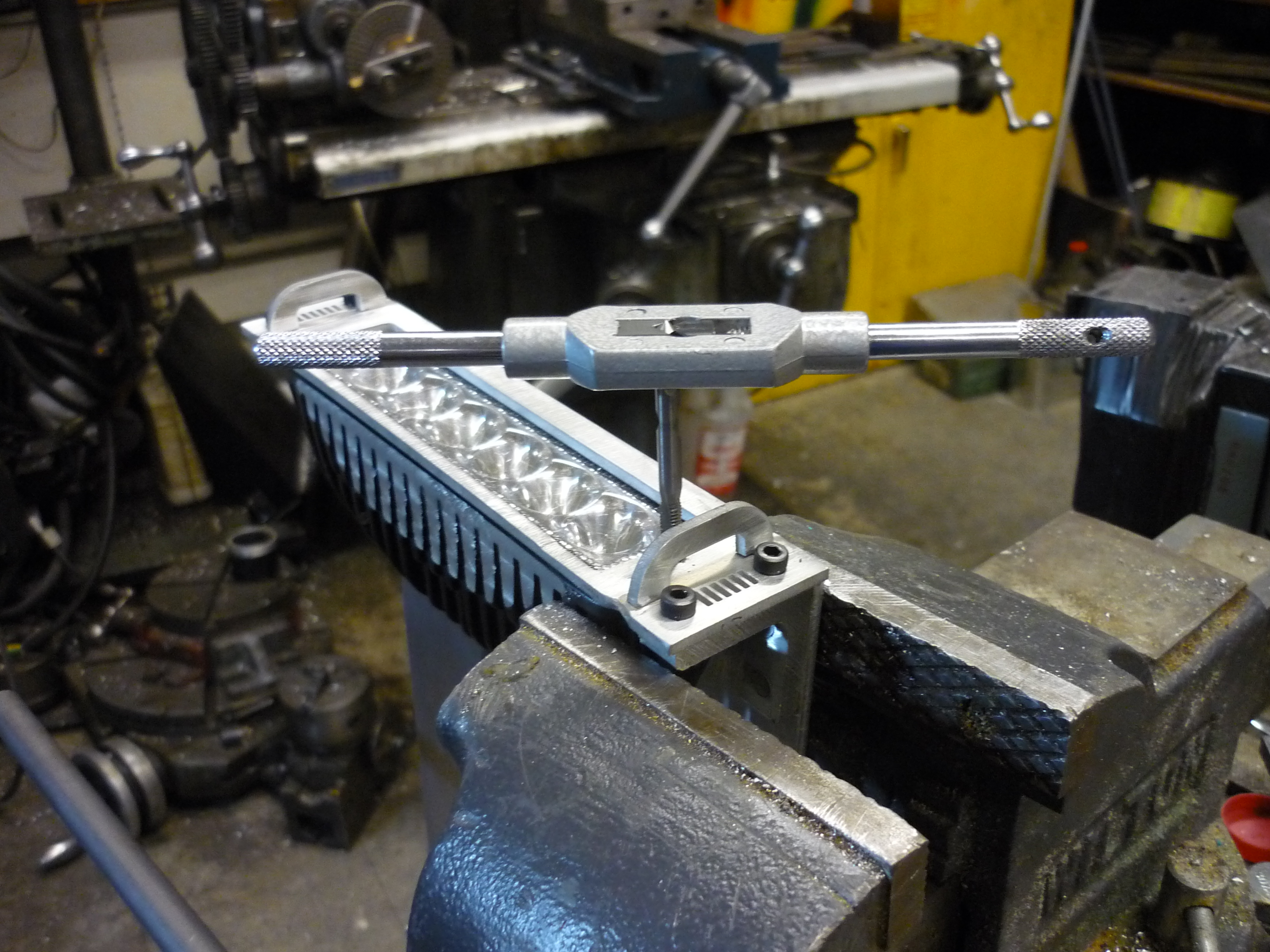
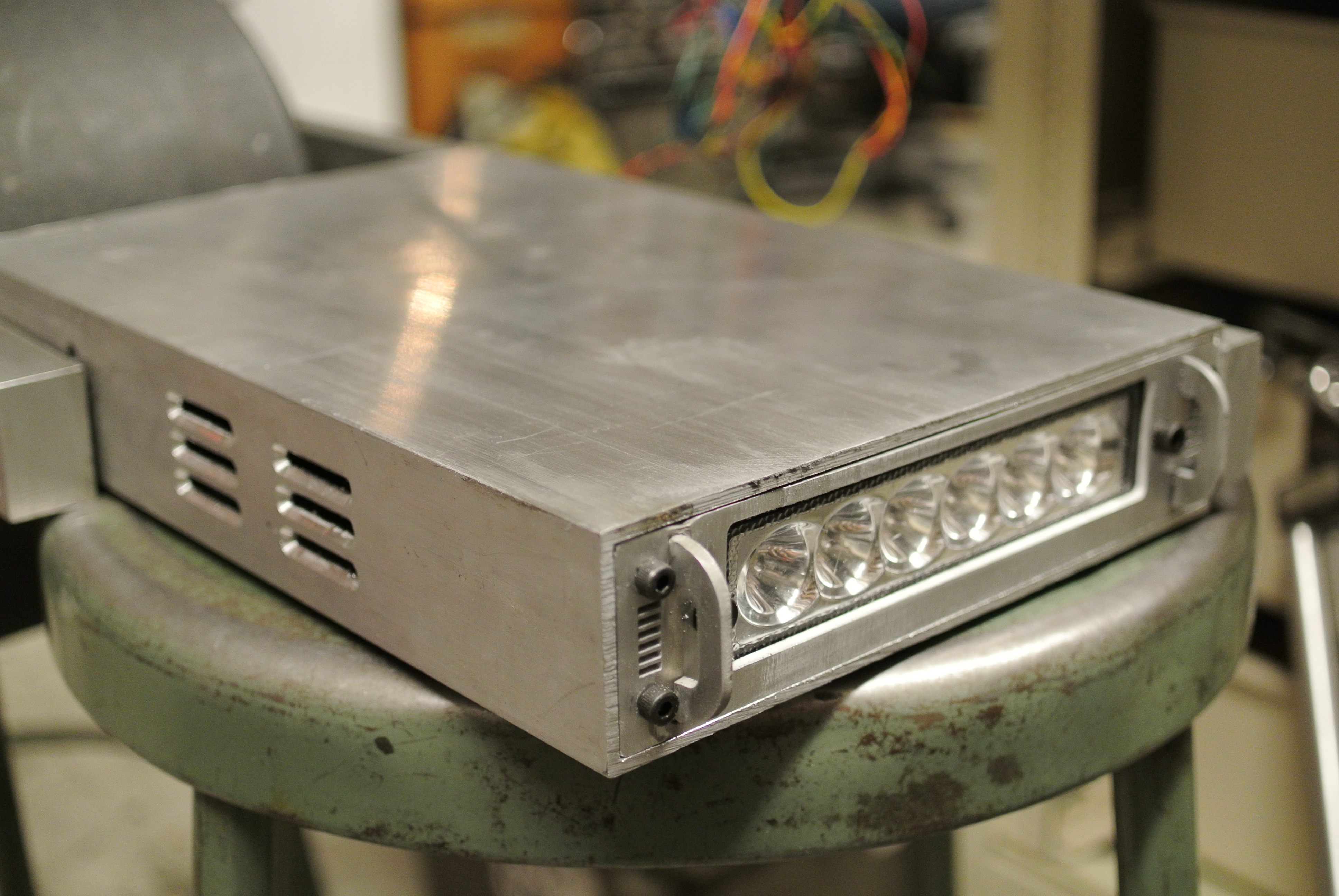
| M4 Cap Screws seal the deal The tapped-led casing worked well and holds the led module in place really well. I was worried that the casting would crack, as, it could have been made of a brittle / super cheap aluminum, but everything seemed to turn out fine. |
 |
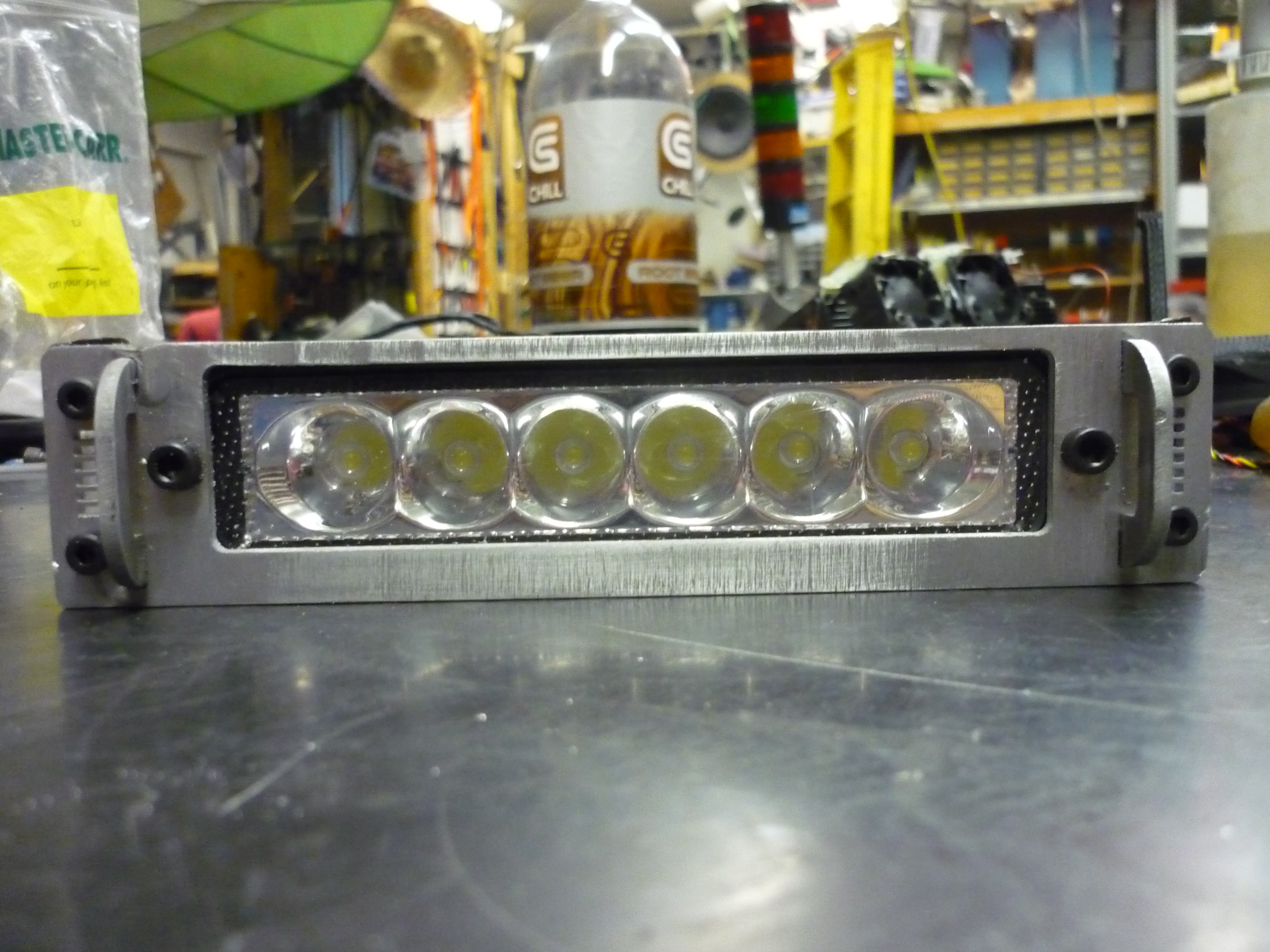 |
| Swanky photos of the front facing mount. Everything fit together fairly well, the 'squeeze mounts' mated together with plenty of room for the tiny handles. The tiny vent holes are intended for front-facing fan exhaust. |
 |
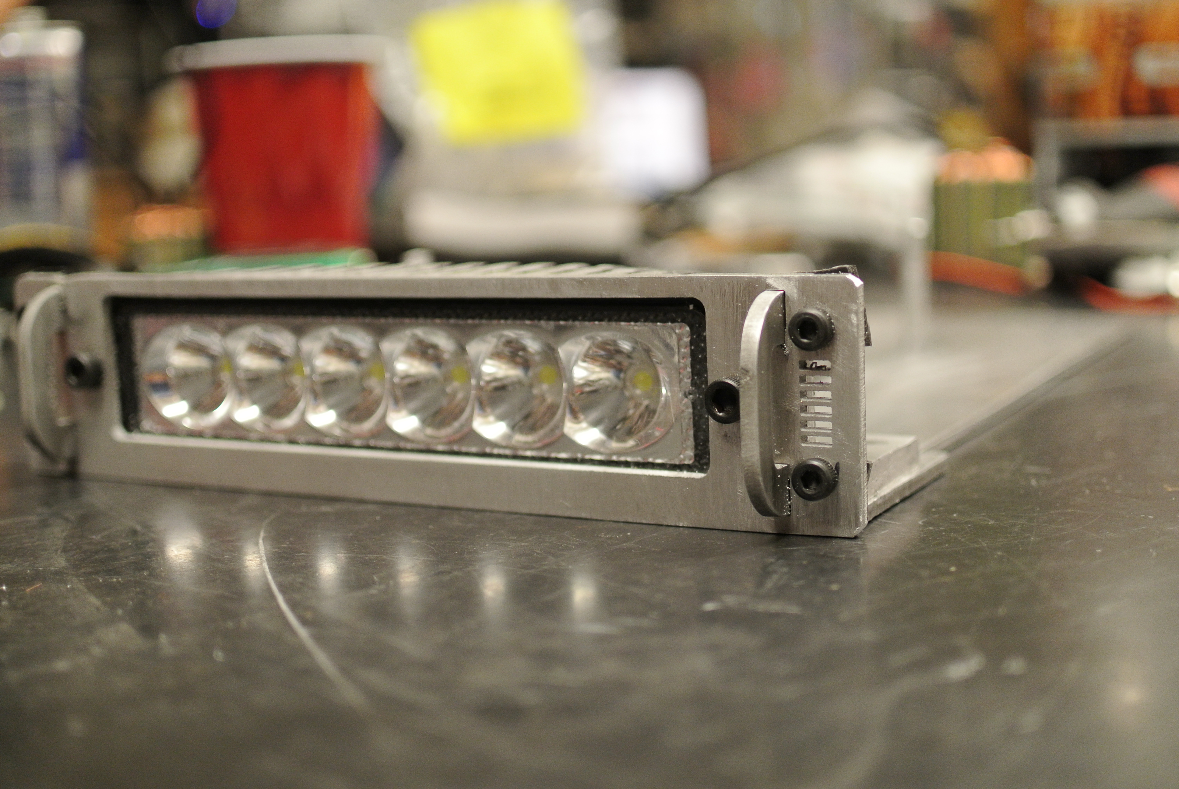 |
| Fit Test IT FITS! everything seemed to line up well and, using the rubber-spacer displacement mechanism, the module held in really well, without shifting about, when tugged on. |
 |
 |
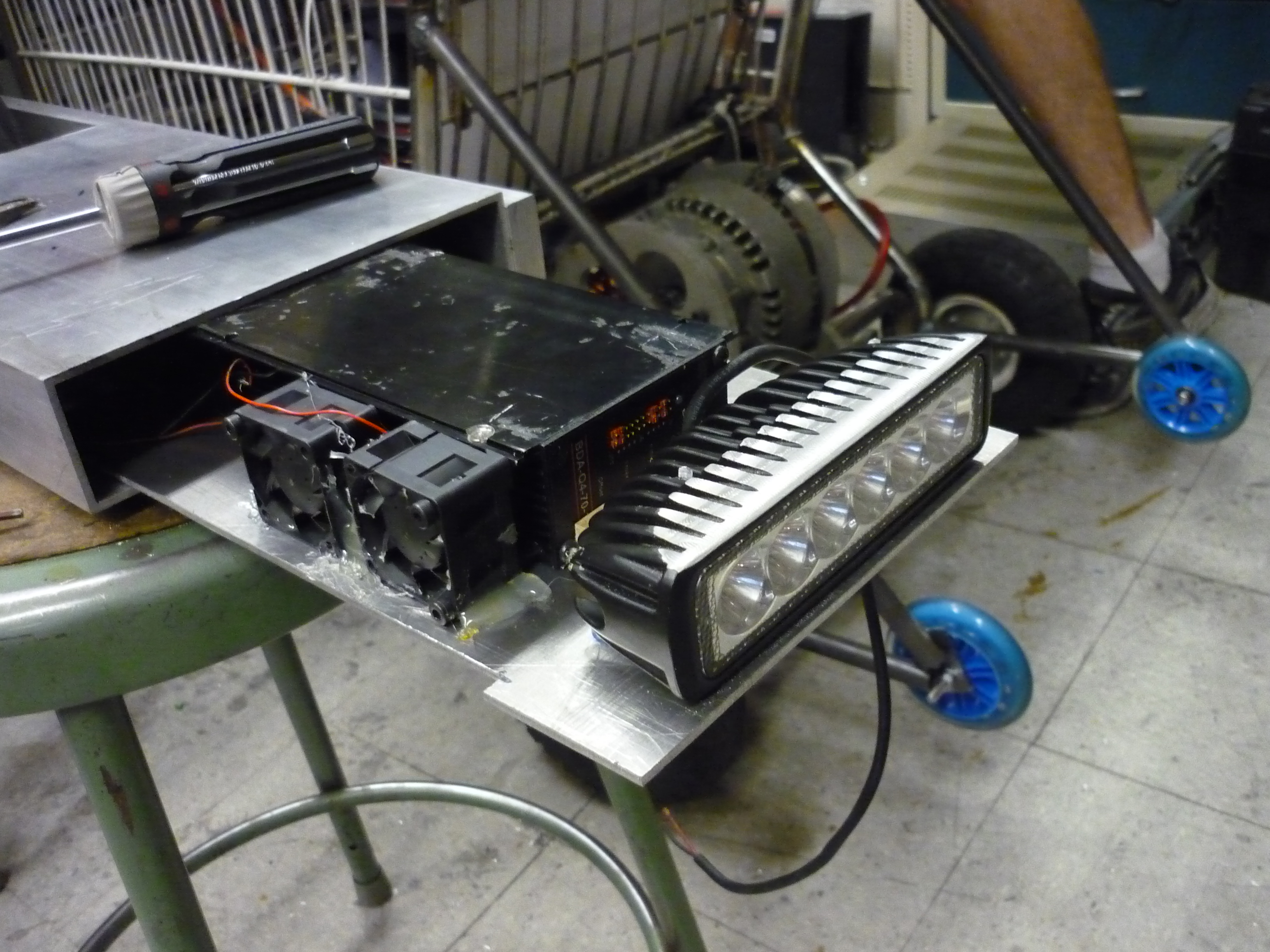
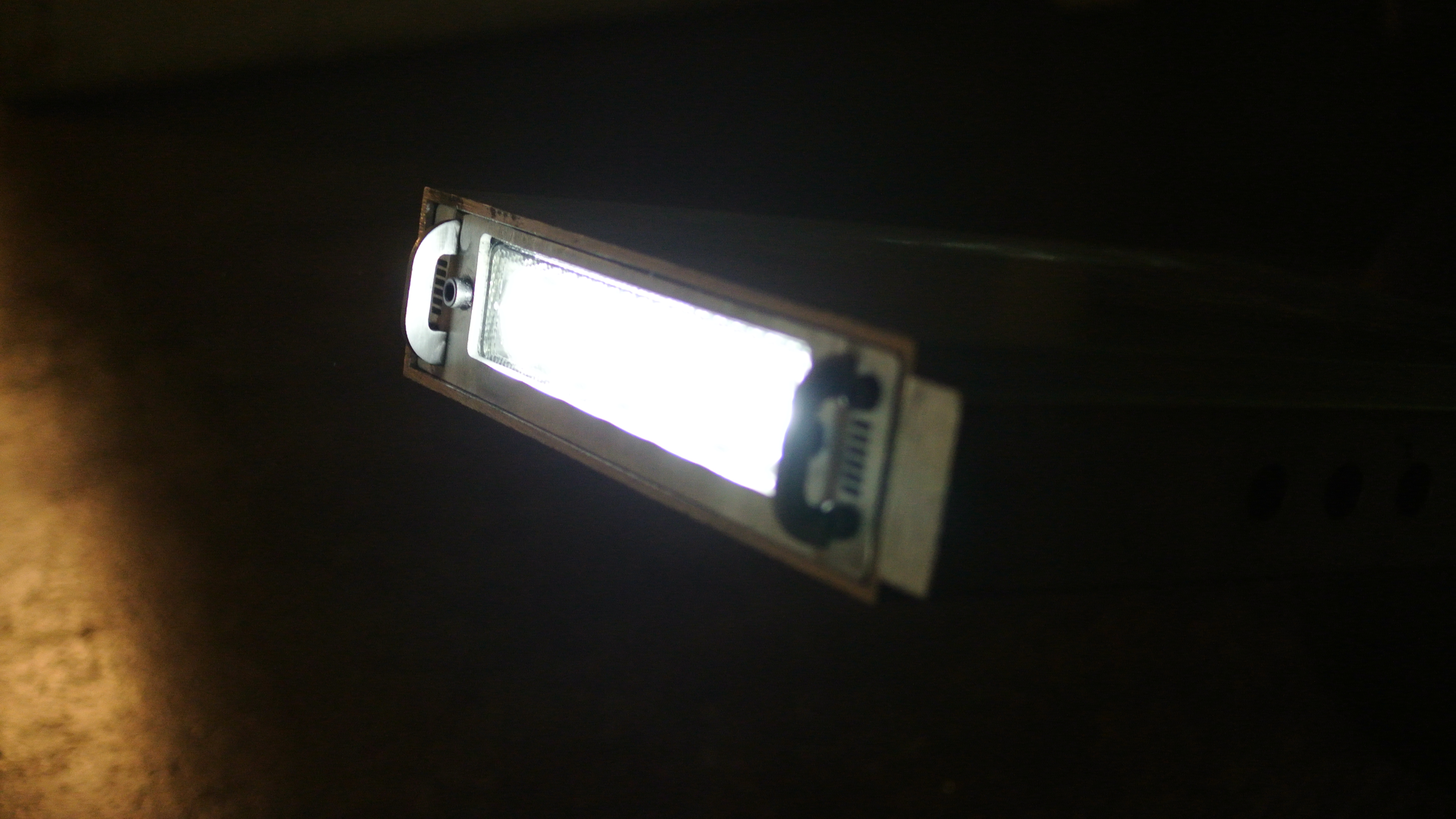
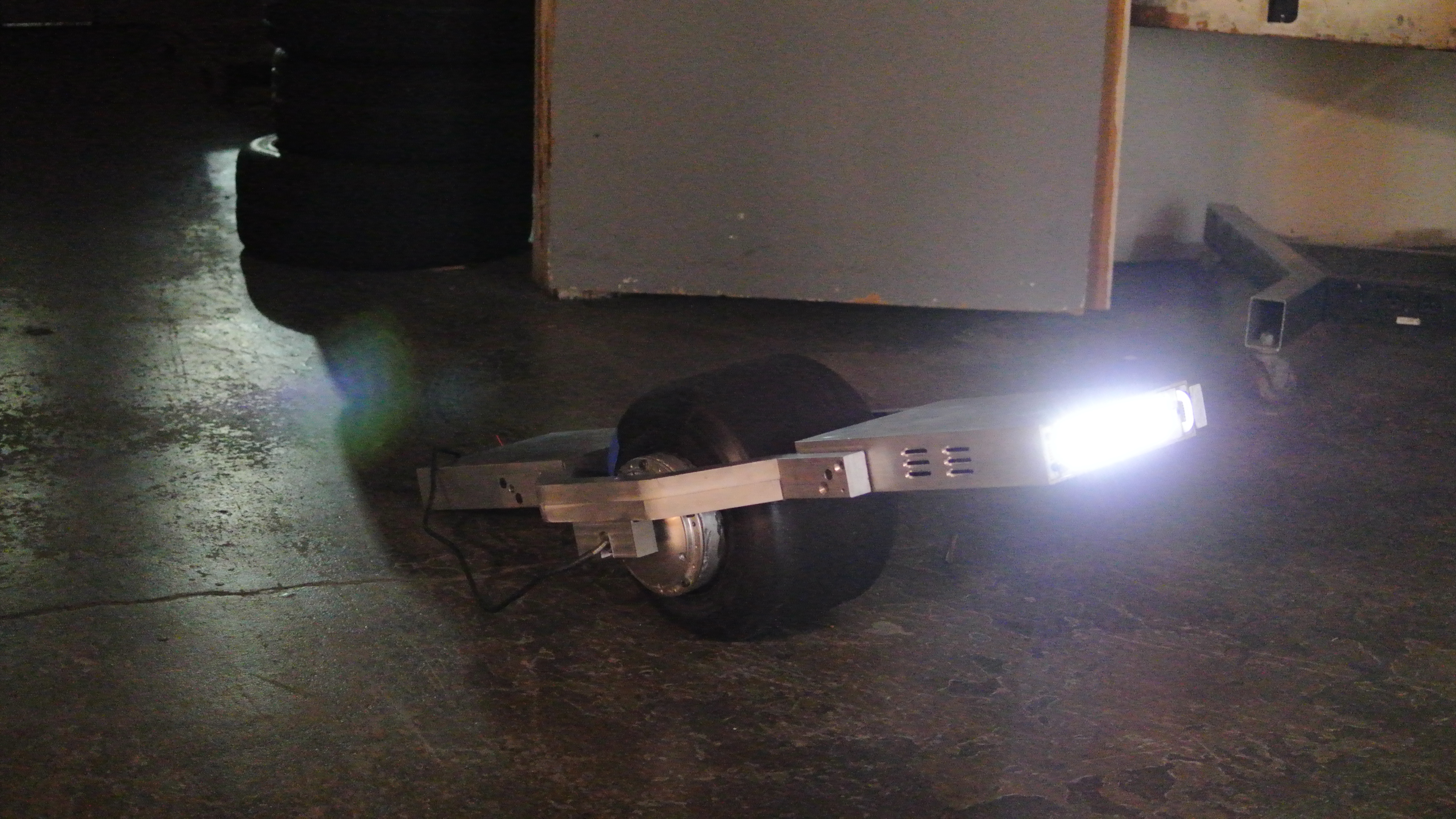
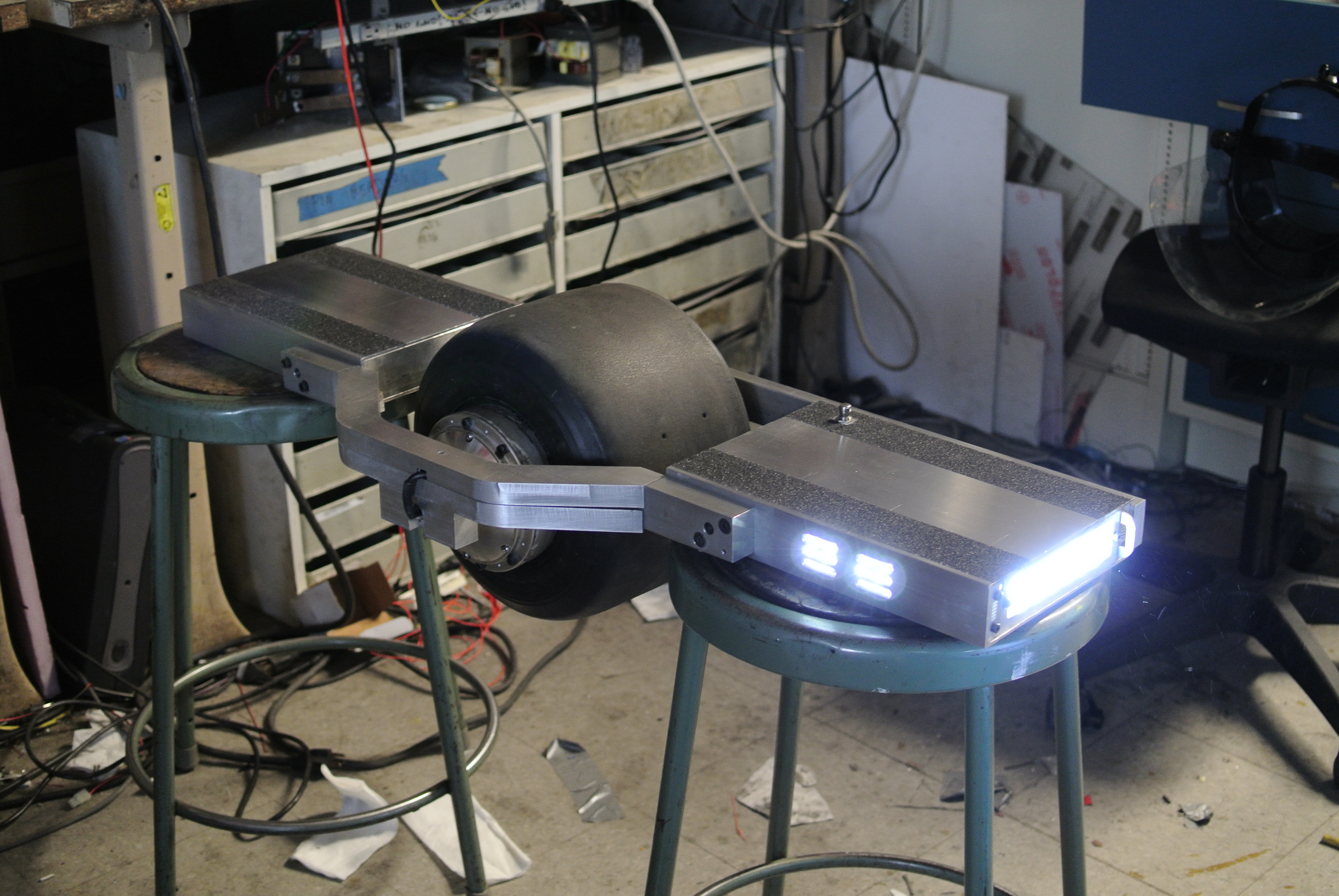
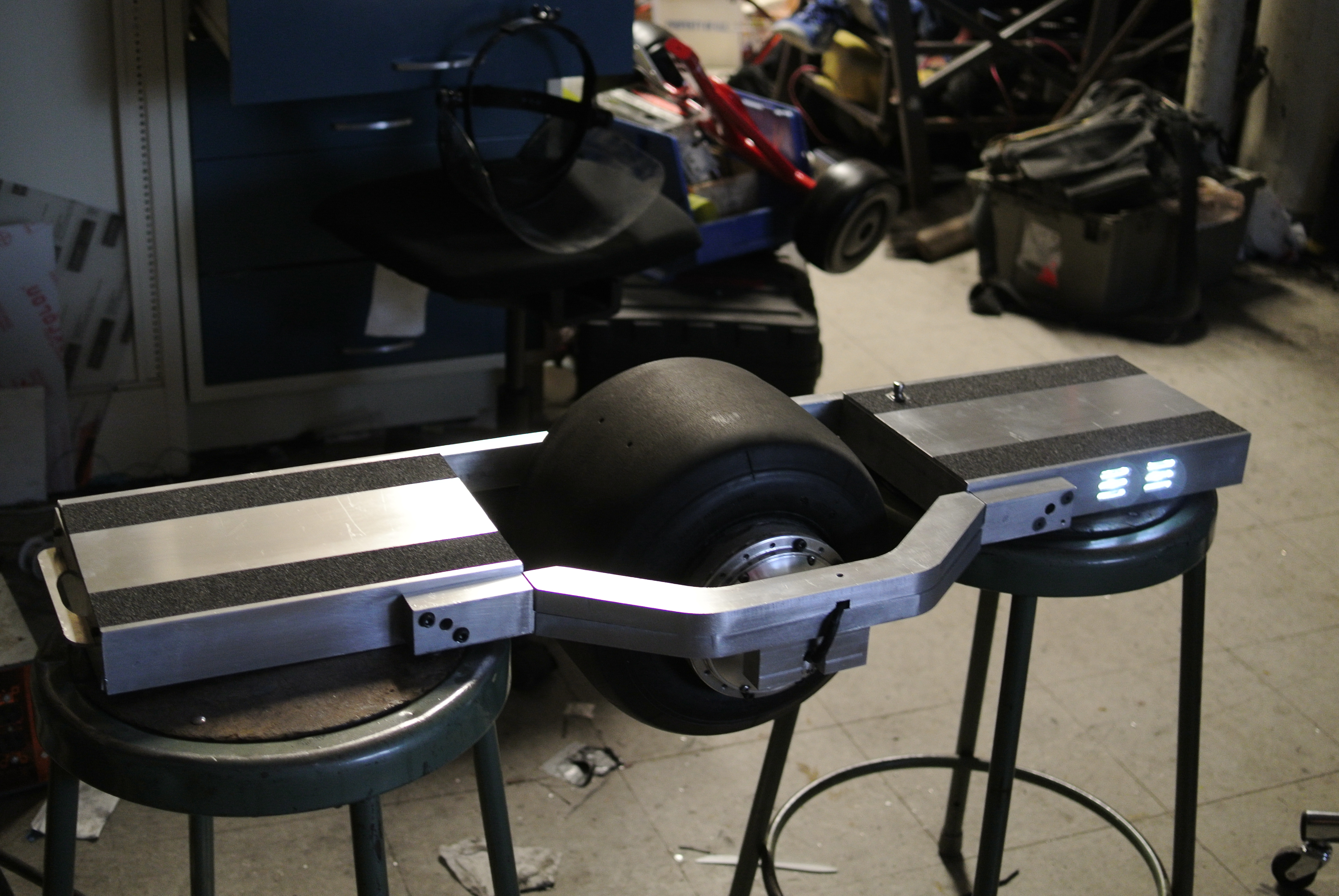
| Firing
up the headlight The LED module turned out to be super-bright. The projection looked to be fairly tight, in terms of dispersion angle. I'm a bit concerned it will be too-bright, so i may implement a 'angle from ground greater than ~+10 degrees, dim headlight' function. I need to verify that the led module does not have an internal dc/dc converter, as pwm'ing into a converter would end poorly. |
 |
 |
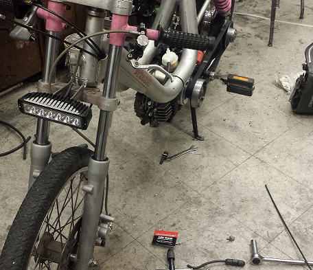
| Lending
the light I lent this led array to a comrade for a weekend trip and unfortunately the whole moped was stolen later the next day. I attribute the thievery to the sexy led module, so clearly I was on the right track. If you see a moped with a pepto-bismol paint job on the east coast, shot an email over! |
 |
| Battery Pack |
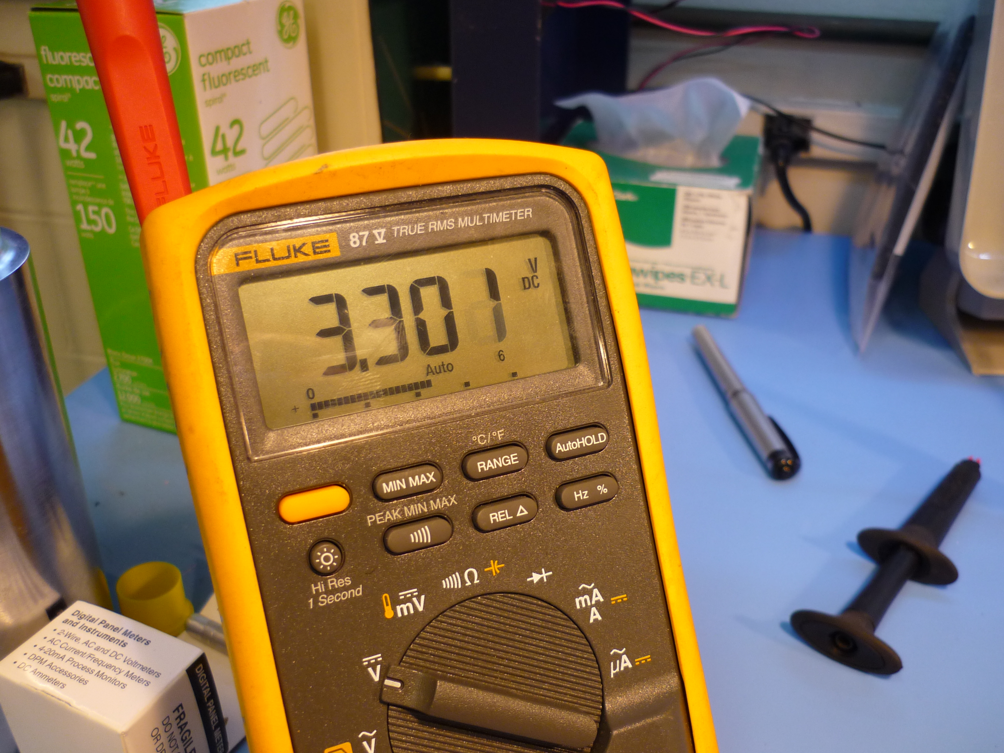
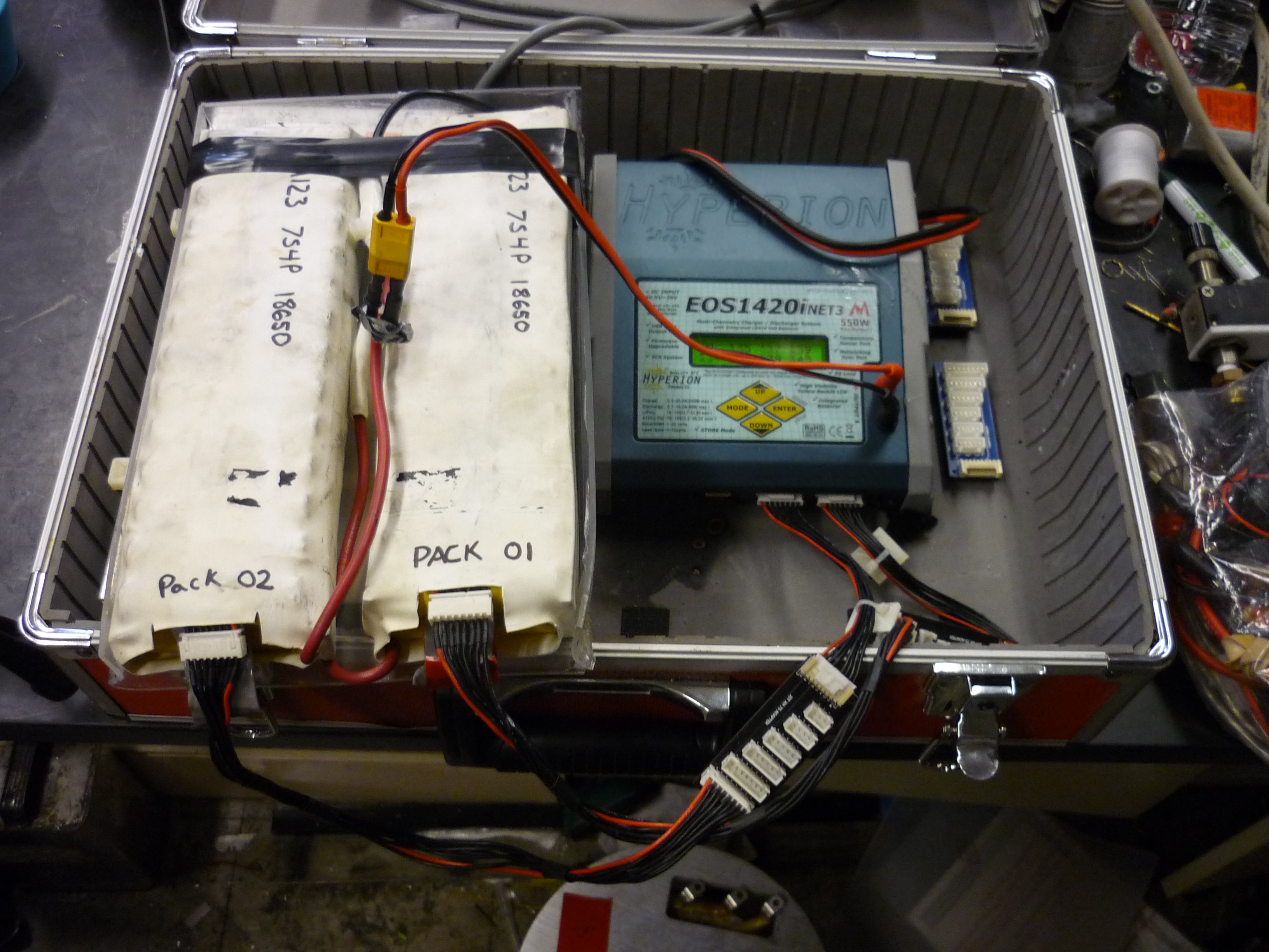
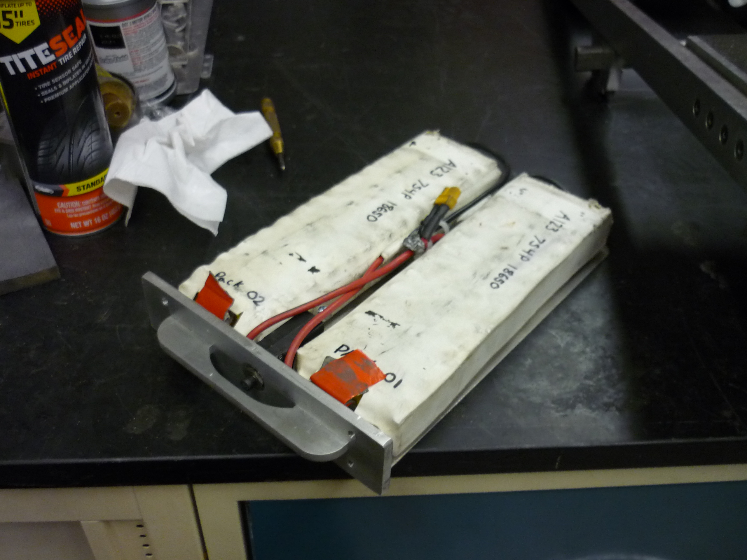
| After building the first pack, I made some observations and notes about improvements to the design and made a 'backup' pack. This time i opted to use a more common form-factor cell, the 18650. Shown (right) is a box of A123 18650 cells from circa 2009. Each was oddly contained in a small plastic zip bag. I opted to stick with a 14S4P configuration. I went through and metered 56 cells, to verify that they were in decent shape. Surprisingly only two out of the batch were below 2v, all the remainders hovered at 3.30 - 3.32V. | 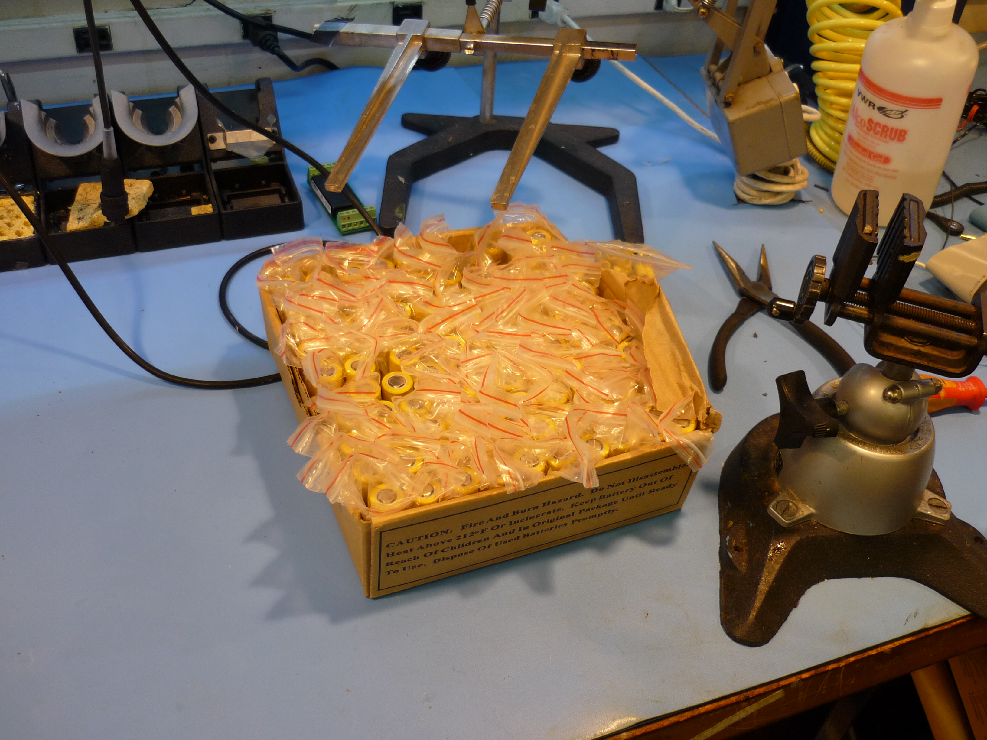 |
 |
| The plan was to continue with a 14S 4P pack, as the voltage requirements were still present. Each cell is approximately 1 to 1.1 ampere-hours, so this would make a roughly 4-4.4 Ah pack, plenty for cruising about. Importantly these cells have a fairly low impedance, so pulling high currents is well within the designed operation of the cells. It is important to note, standard laptop cells will not enjoy 10C discharge rates, please consult an appropriate data sheet if you'd like to use different cells. This pack features the slide-in-lock mechanism from the previous pack, as well as an integrated circuit breaker and charge connector. | 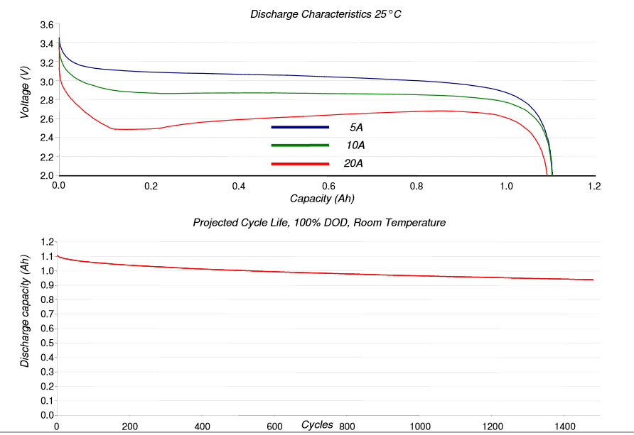 |
A123 18650 Datasheet [pdf] |
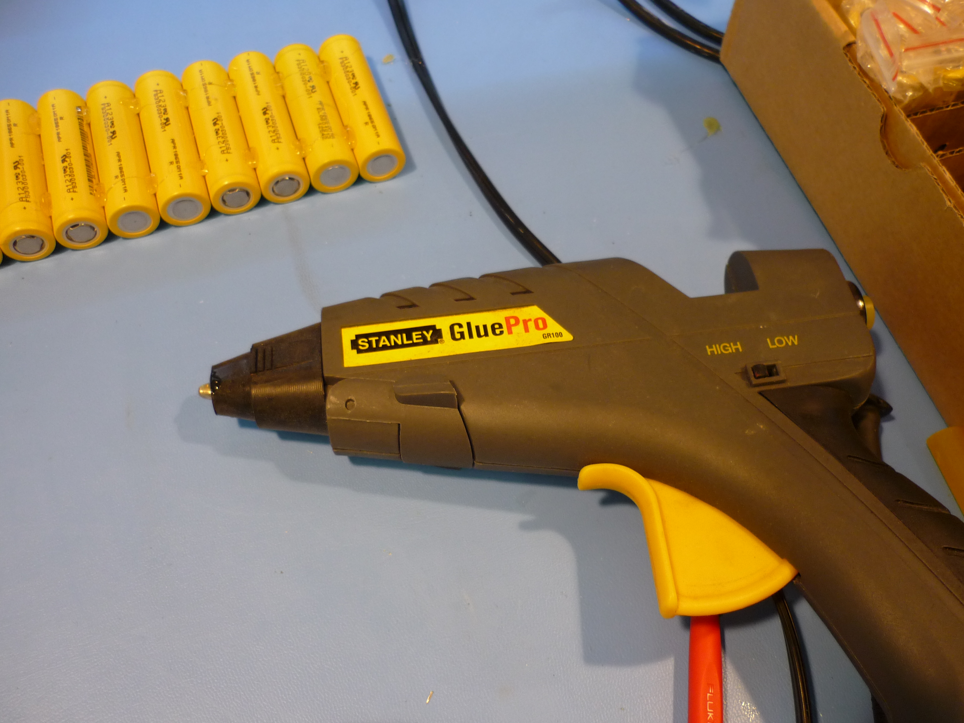
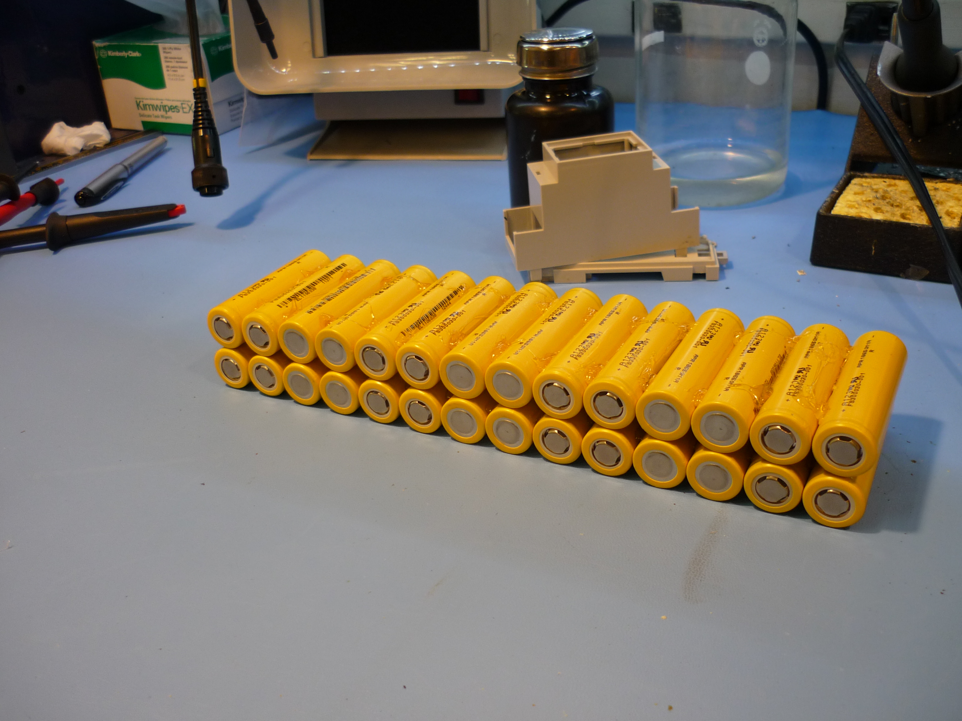
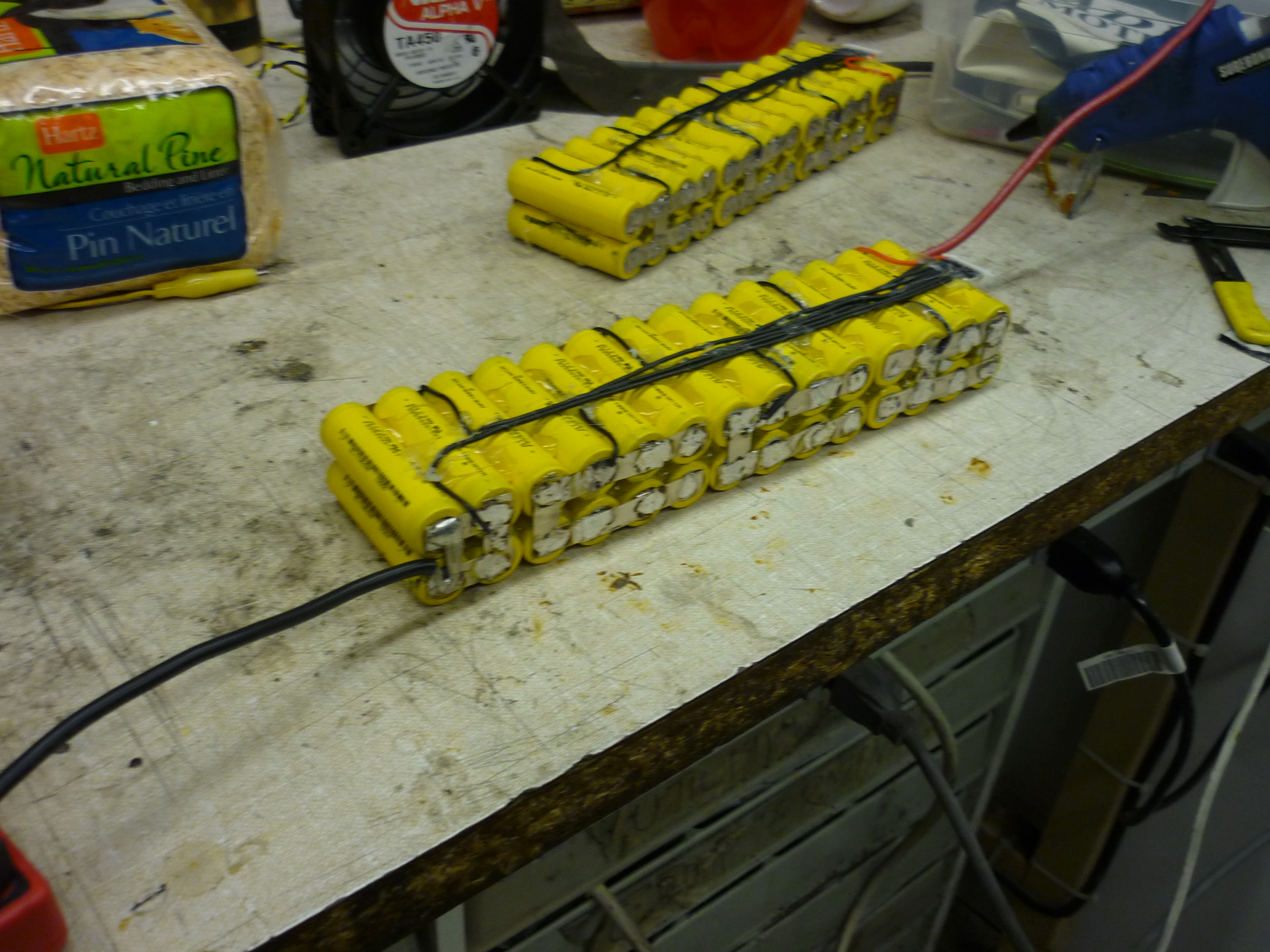
| To build the pack, I started by modeling the layout, verifying everything would fit, and then using a high-temperature hot-glue gun to hold the cells in place. Note the pattern shown allows for two 7S-4P modules, this is advantageous as it minimizes odd current paths and allows for a bit more work space inside the pack. | 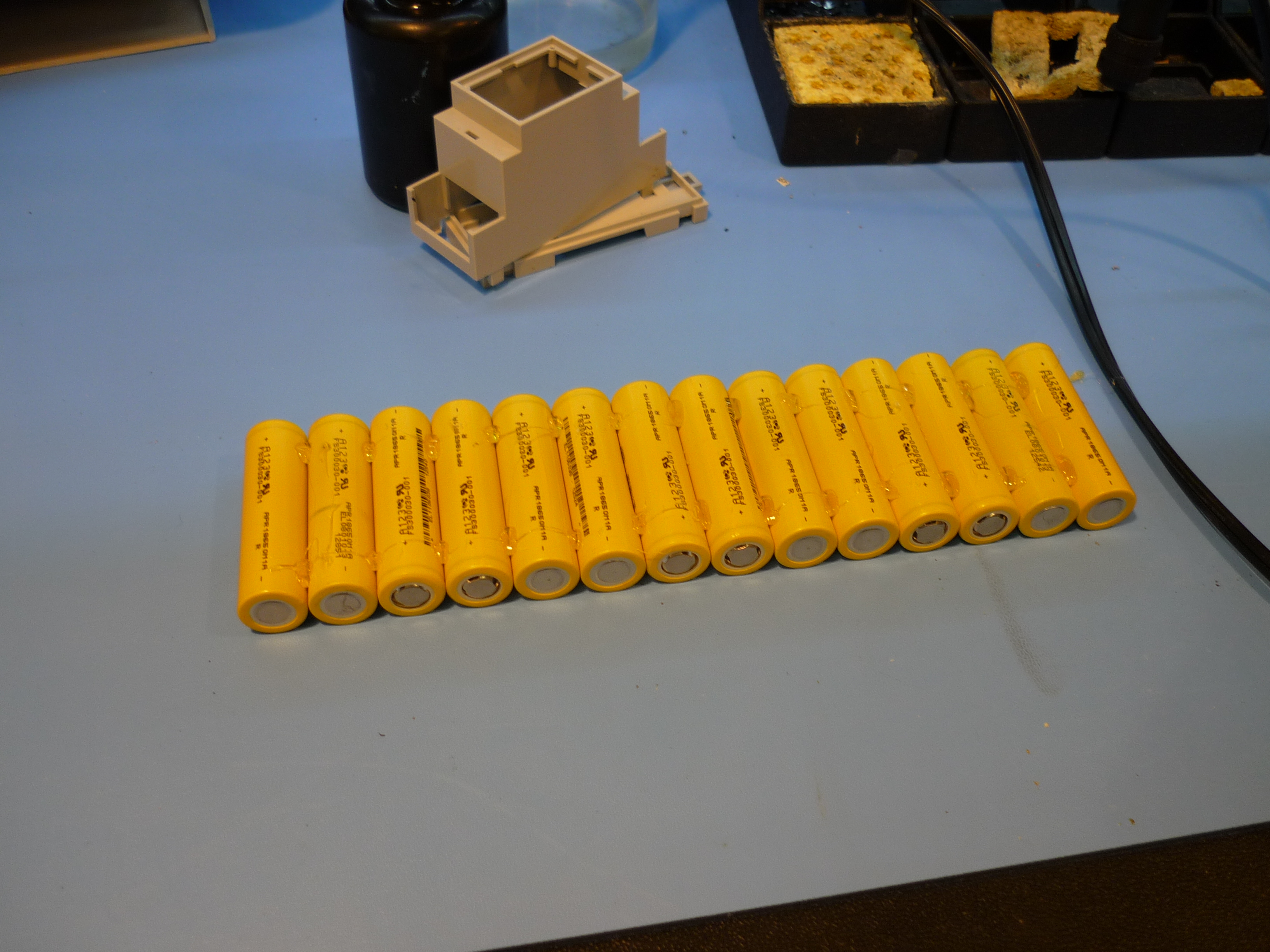 |
 |
| After building two identical strings, they were stacked together and adhered. Note I opted to stack the cells vertically as the intention is to maximize horizontal space, vertical space was available. | 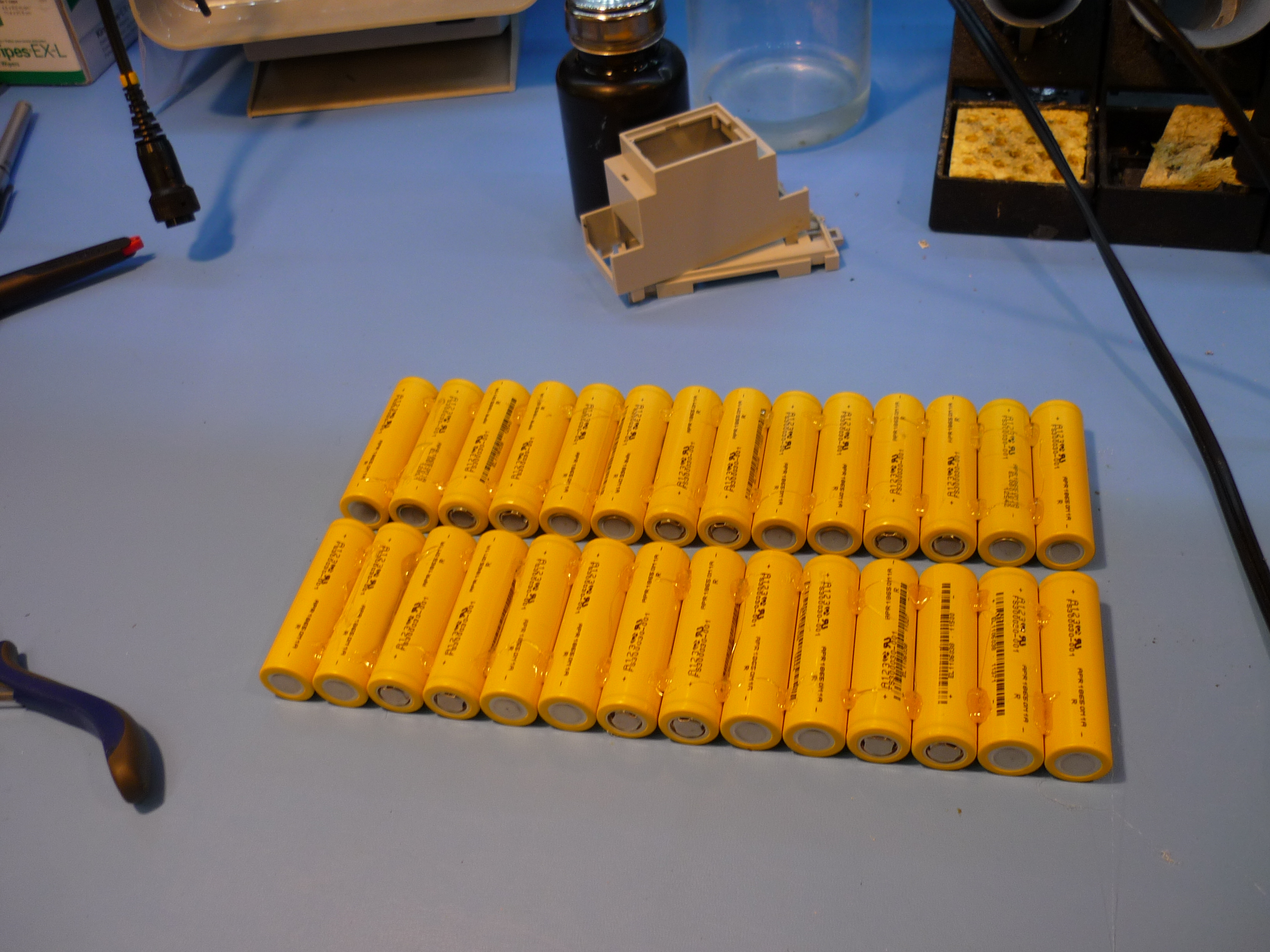 |
 |
| This process was repeated to build the second 7S4P pack. With the two modules in series, it completes a 14S4P 18650 array. Next up, attaching the cells together electrically. | 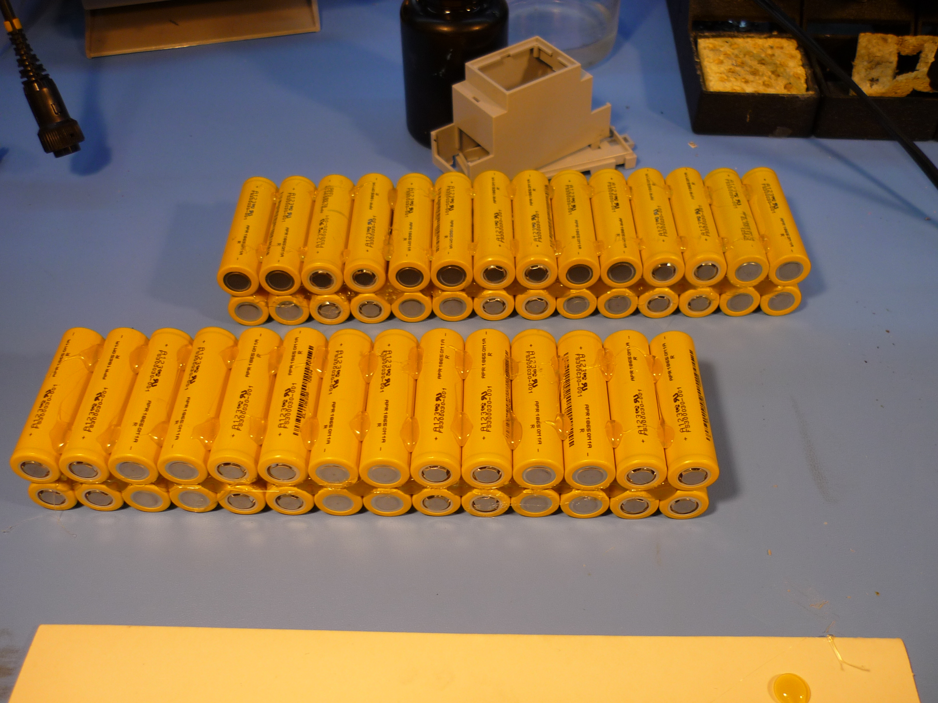 |
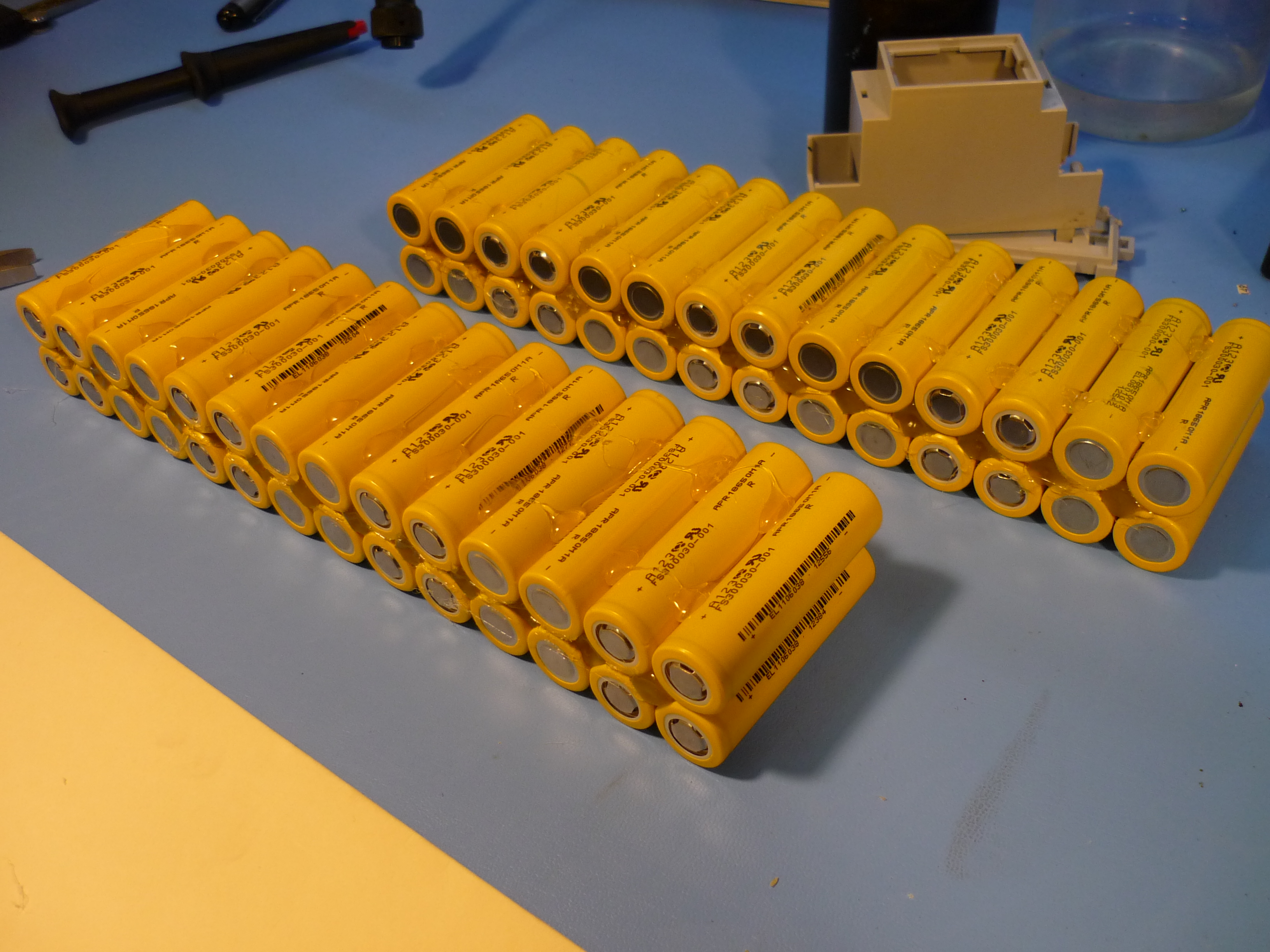 |
| To connect the cells together, solder and copper braid can be used, or thin strips of tin. The packs are soldered together, in groups of 4 cells, totaling up to two modules of 7S4P 18650 cell groups. | 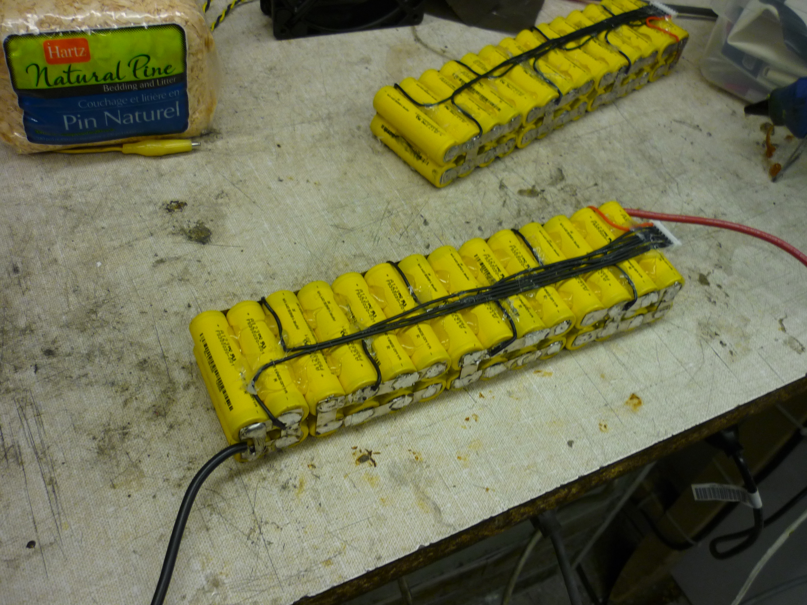 |
 |
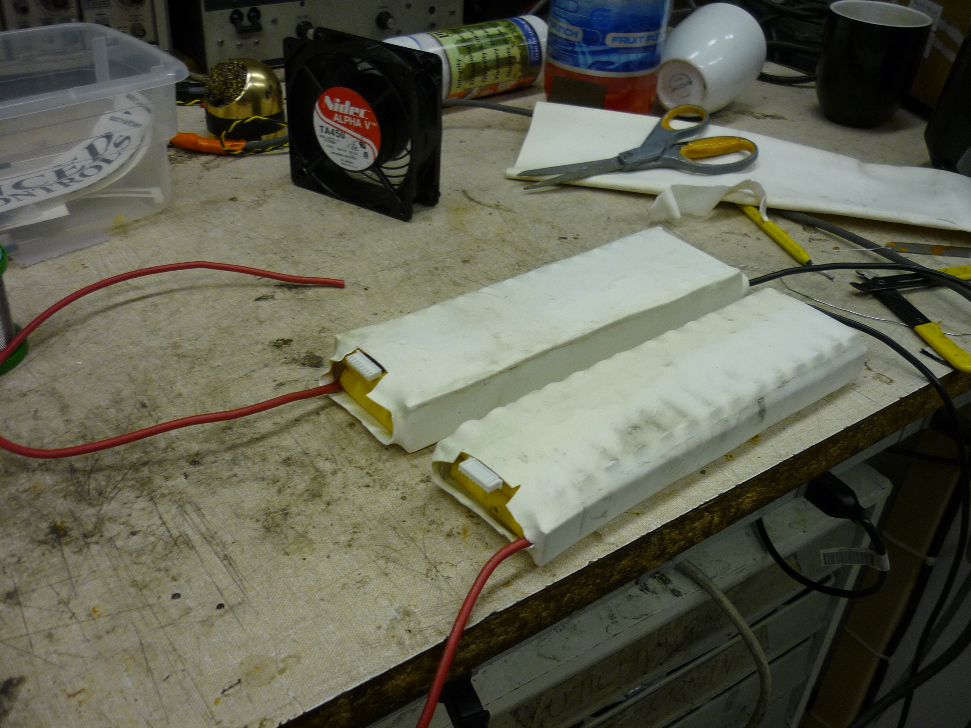
| Heat shrink To seal and isolate the modules, i used some old 4" wide heatshrink. The balance leads are shown poking out of the top of the pack. Each balance connector is a JST 8 pin connector. The packs are shown next to the motor-controller aluminum skid plate. |
 |
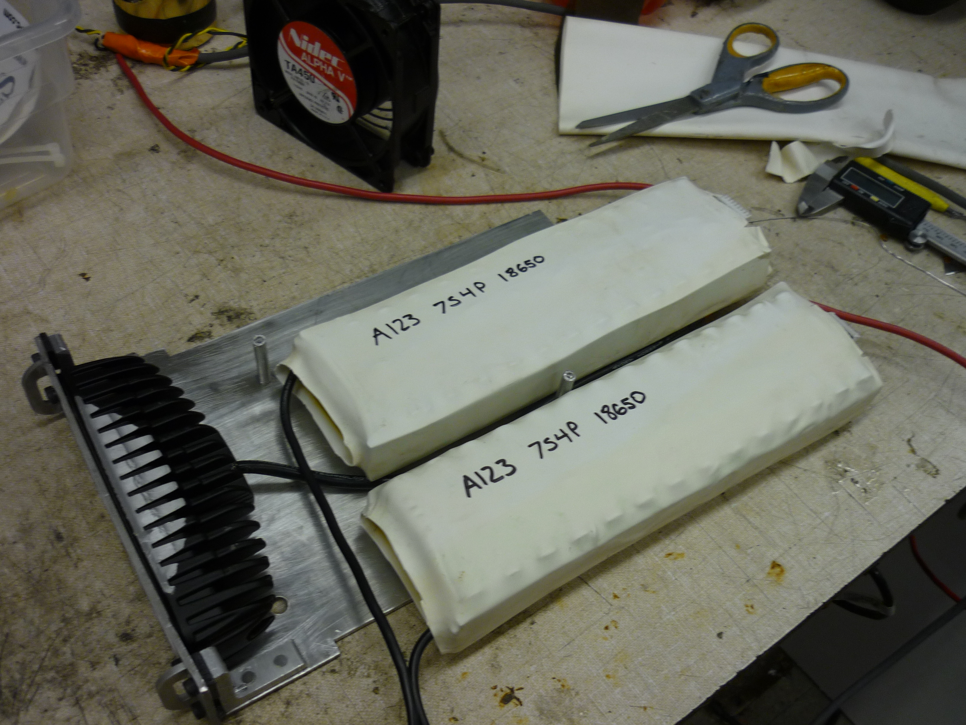 |
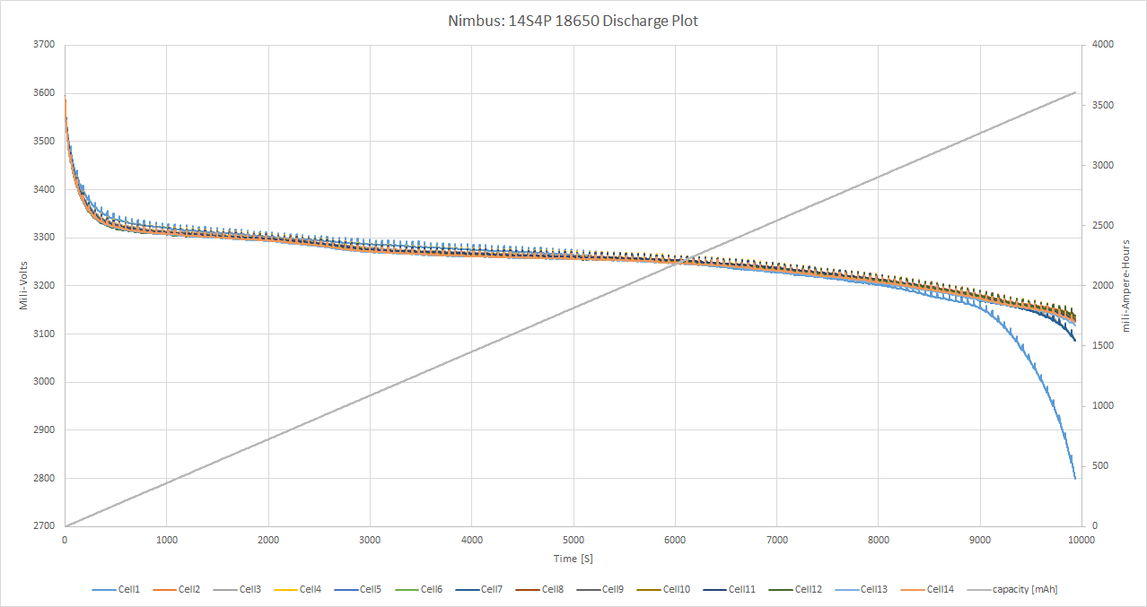
| Balance and Capacity Test A Hyperion 1420i multichemistry balance-charger is used to 'top' balance the two 7S battery modules. Seperating the large pack into two allows for charging of the smaller modules on lower-cost, more readily available 8S balance chargers. For this test I am using a hyperion 1420i, which is able to do the full 14S pack. The module came in at approximatley 3.8Ah, lower than anticipated but still plenty useful. Cell group 1 may have a low capacity cell. Data: [xlsx] [txt raw] |
 |
 |
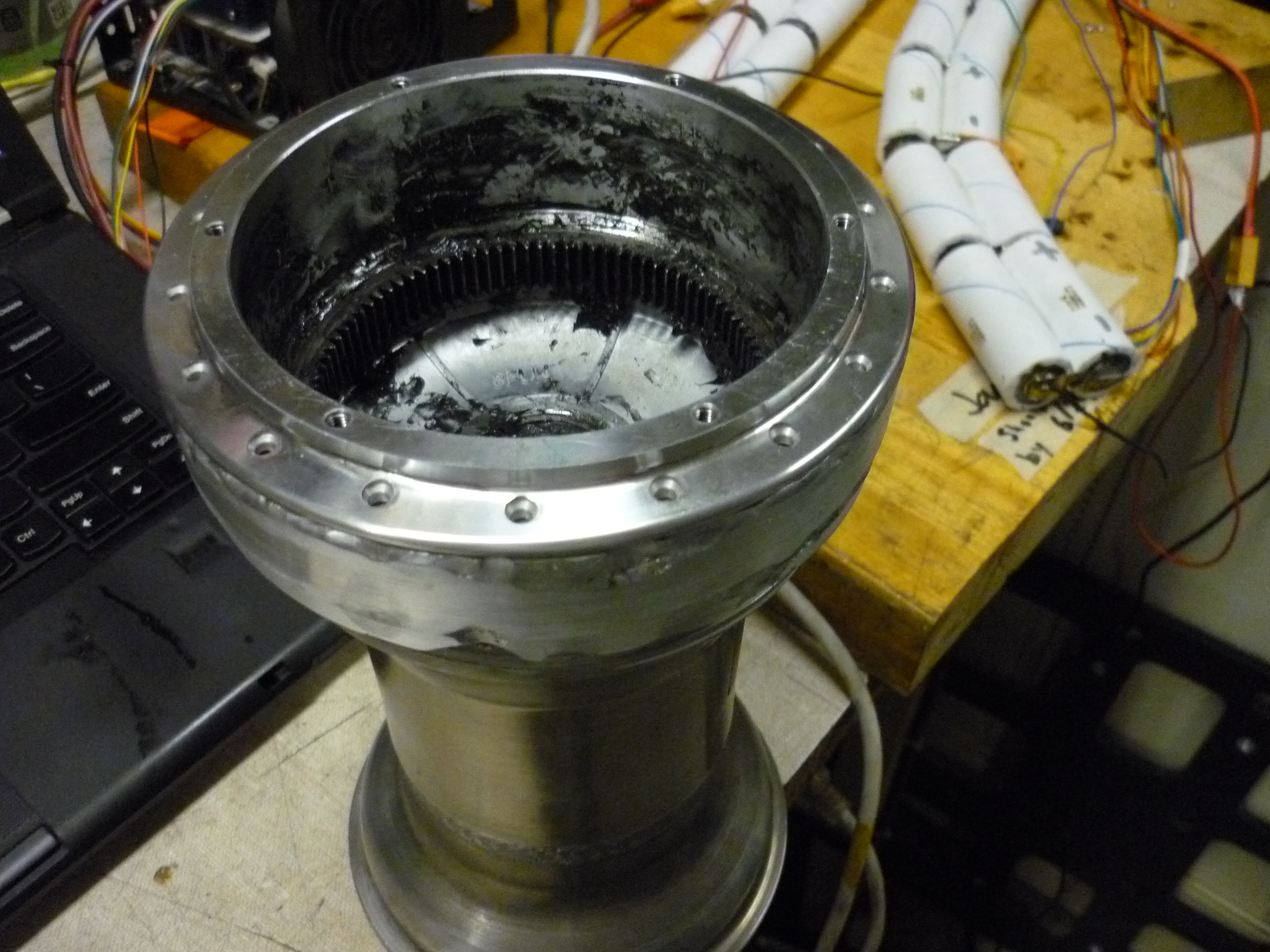
| Removing the 'free wheel' function of the hub-motor and cable routing |
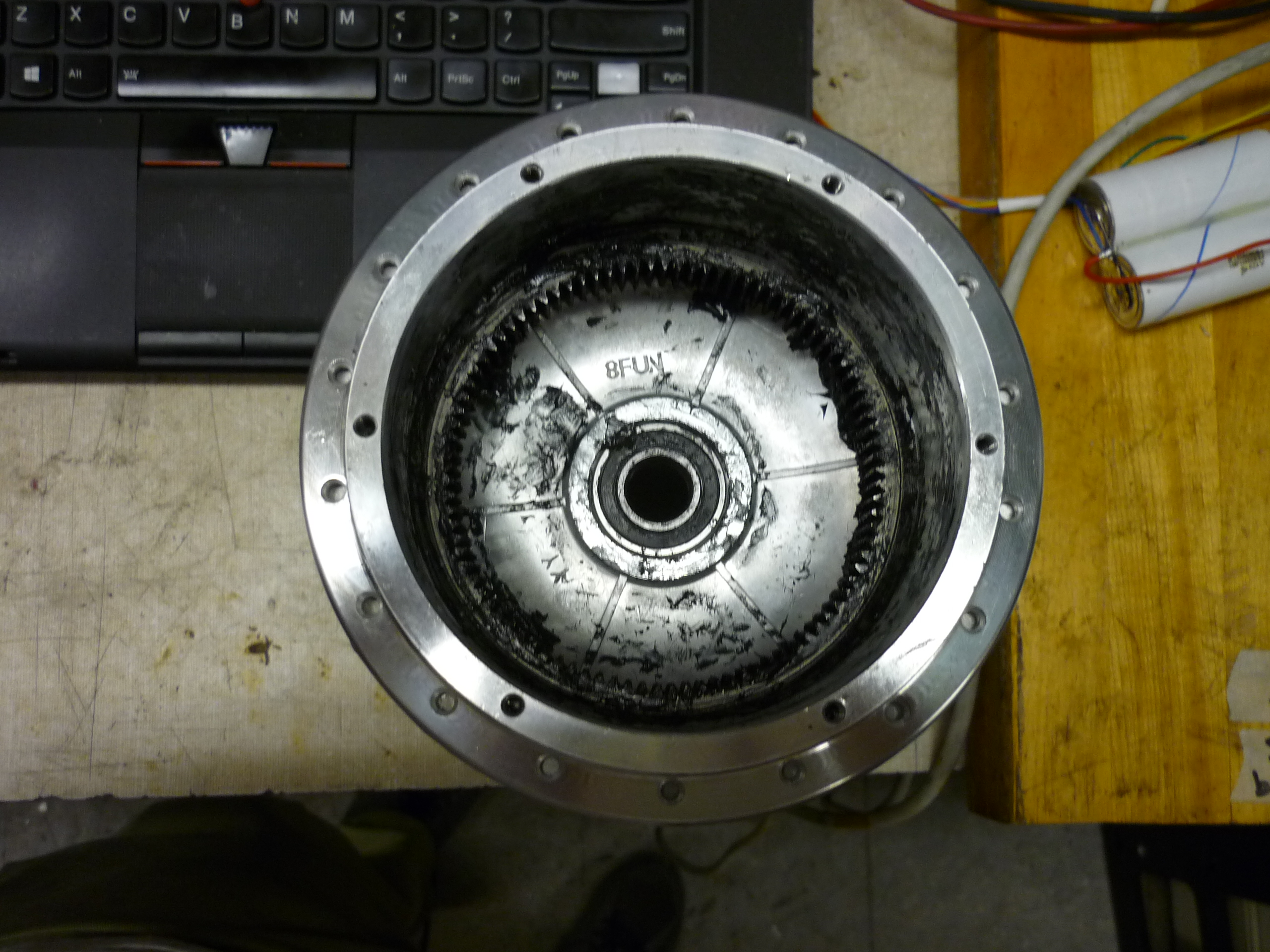
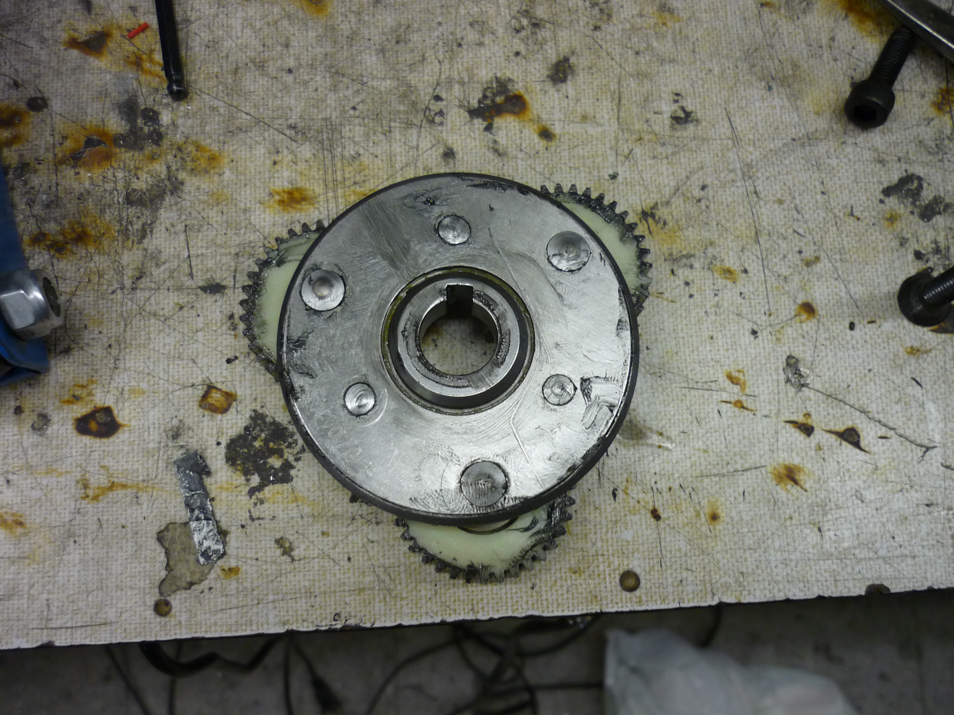
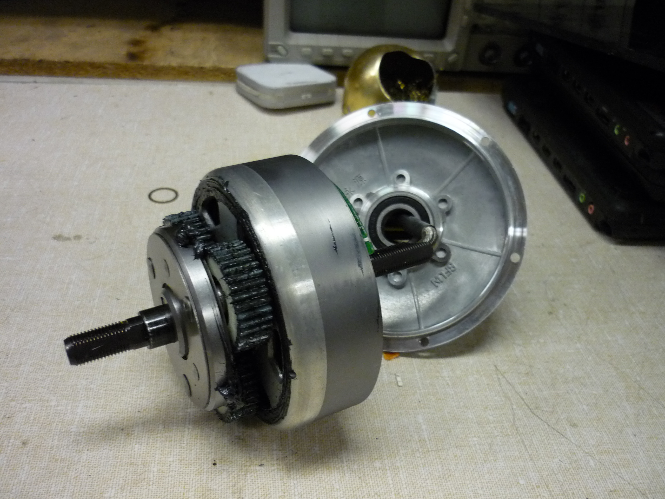
| The stock hub-motor has a large internal free-wheel. In one direction the applied motor torque is transmitted through the planet gears, out to the ring gear and to the bike-wheel, in the reverse direction, the ring gear / bicycle can coast. This is great for an E-Bike application where pedal-power can keep things moving uninhibited. I needed to transmit torque in both directions on the balancing skateboard, so the one-way bearing needed to go. Instead of removing it, I opted to weld across the bearing surface. |  |
 |
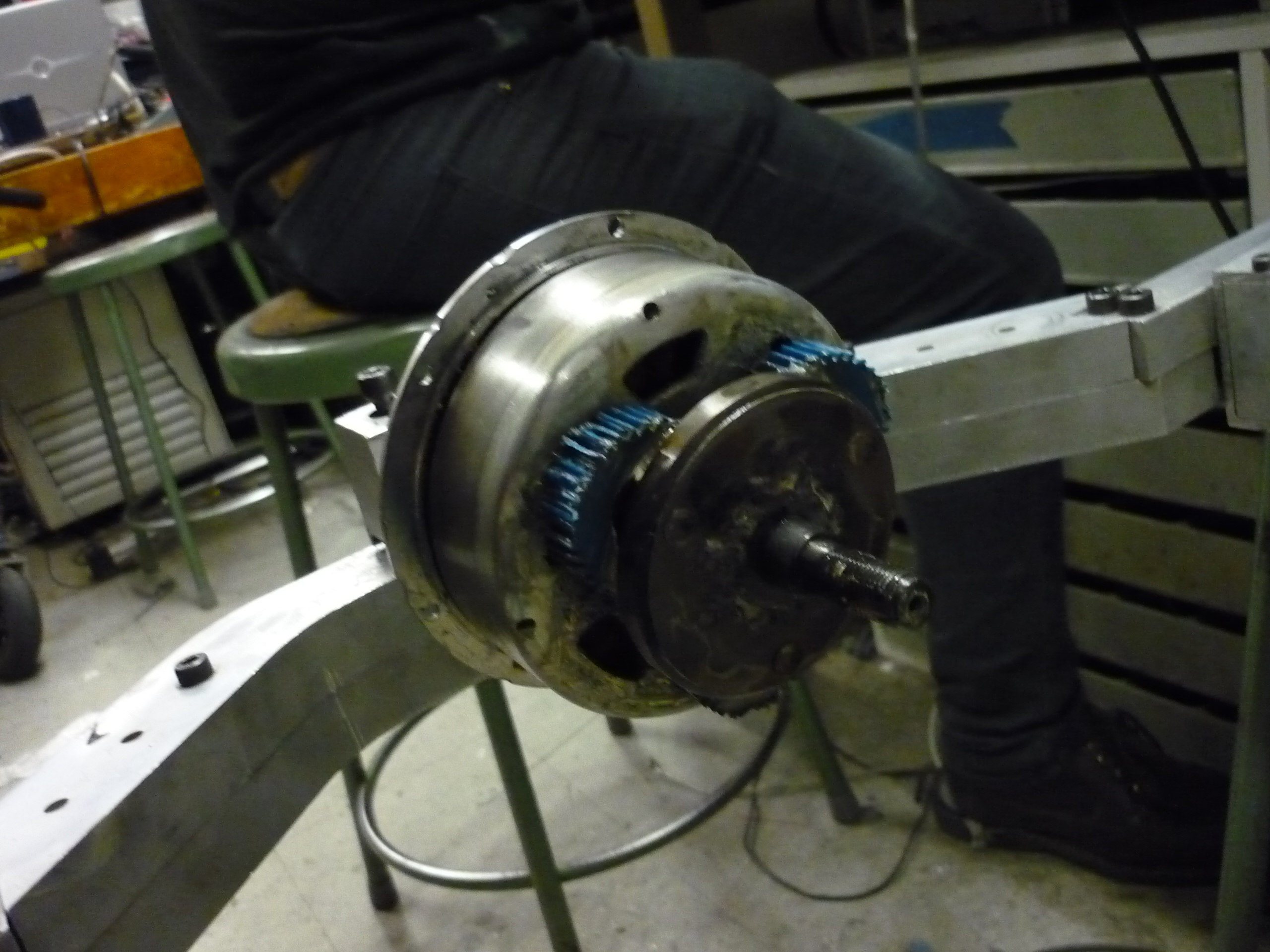
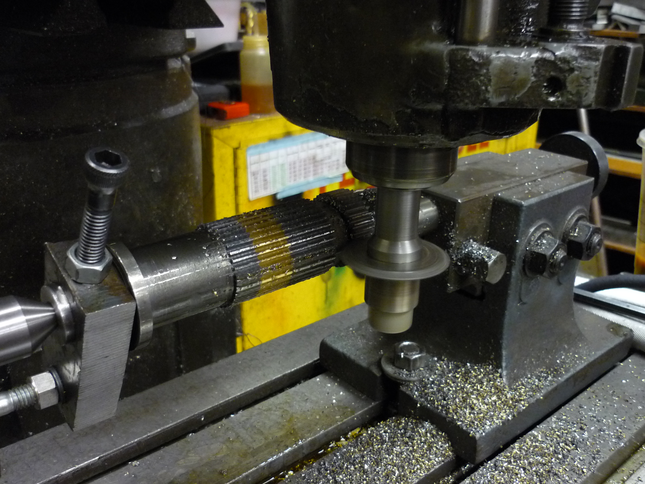
| After significant cleaning and surface prep, I hauled the planetary geartrain up to DLAB's welding shop, and TIG-welded from the carrier to the sungear mount. The metal that the carrier was made of was some form of steel, and did not enjoy being tigged. The inside of the bearing mount was also packed with grease, and keeping the weld surface clean was, interesting. The ~5 bridge welds would have to do for the time being. | 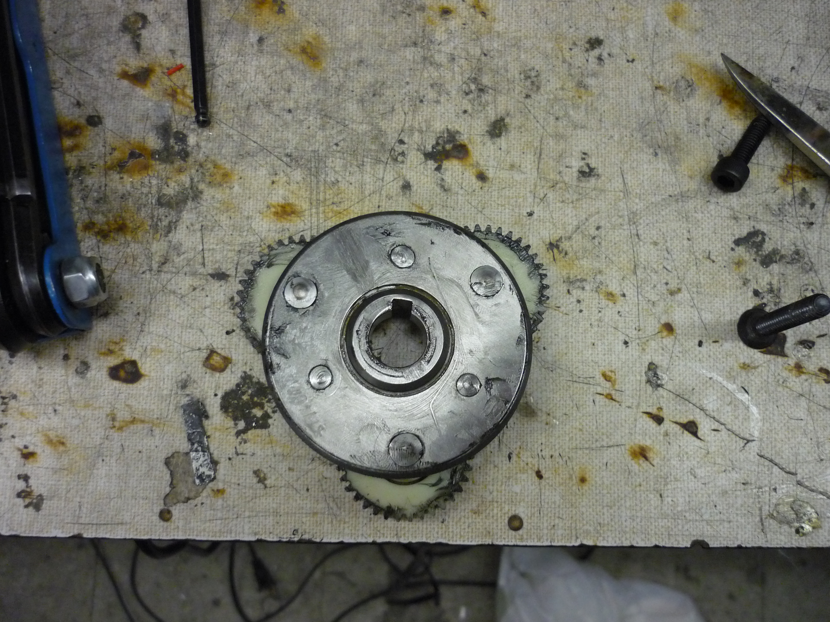 |
 |
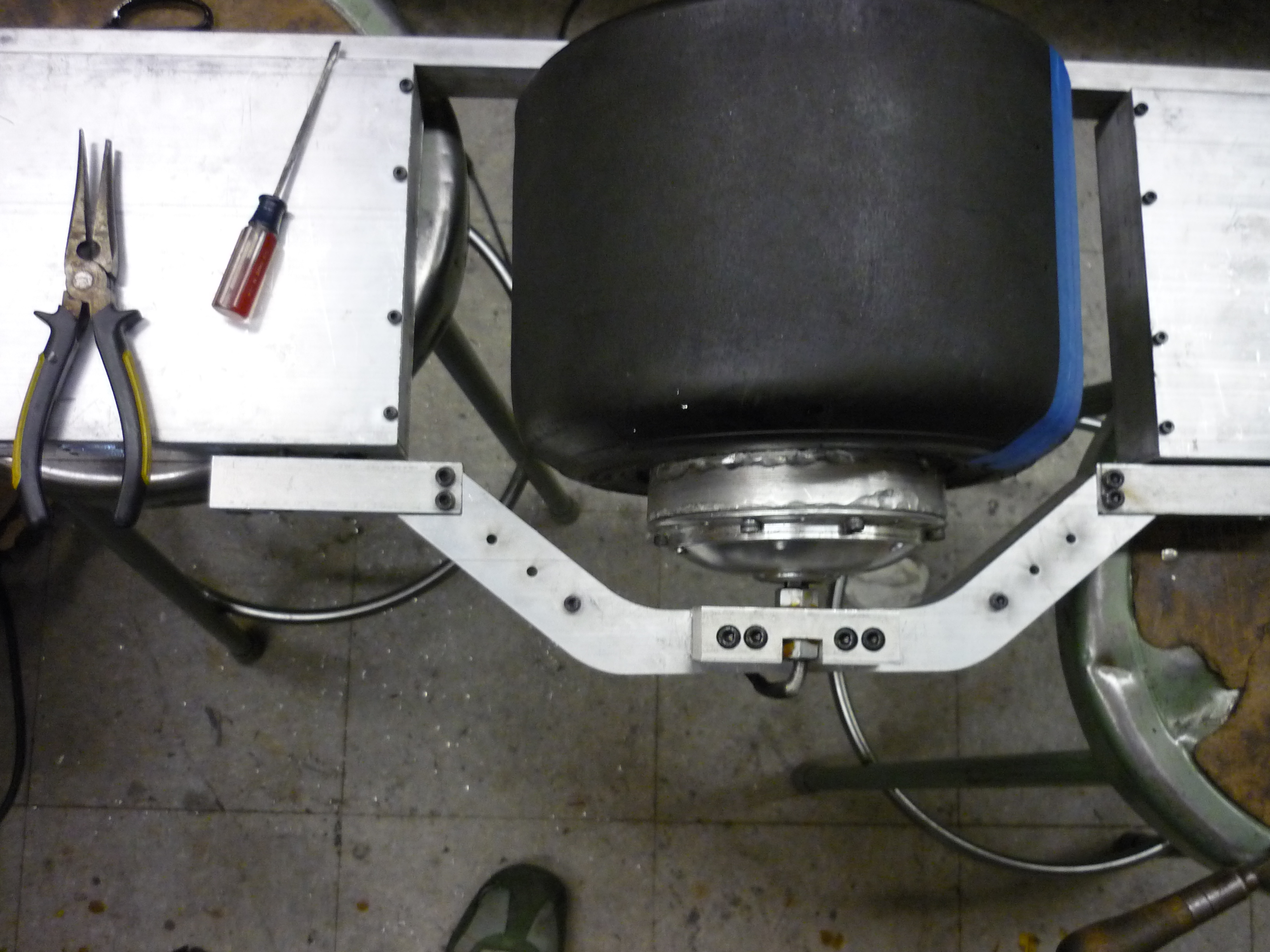
| Interesting cable management The hub motor routed its cabling (3 phase feed, sensor wire, sensor power) through the center of the axle, which i thought was fairly nifty. The controller box hides inside the aluminum extrusion, and I opted for a 'hidden' cable management scheme. The swing-arm setup consists of two pieces of 0.75" thick 6061 aluminum bolted together with M6 screws. By hollowing out a portion of the swing-arm insides I can 'hide' the motor drive cable and help prevent it from being chewed up during normal use. |
 |
 |
| I started with a 0.25" endmill and worked my way from the motor controller side of the setup to near the center, where the motor cable would enter. The cable is 0.20" wide, so this was a bit of a tight fit around corners / cable entrance. Further milling is required to route the battery supply voltage to the controller side of the skateboard. | 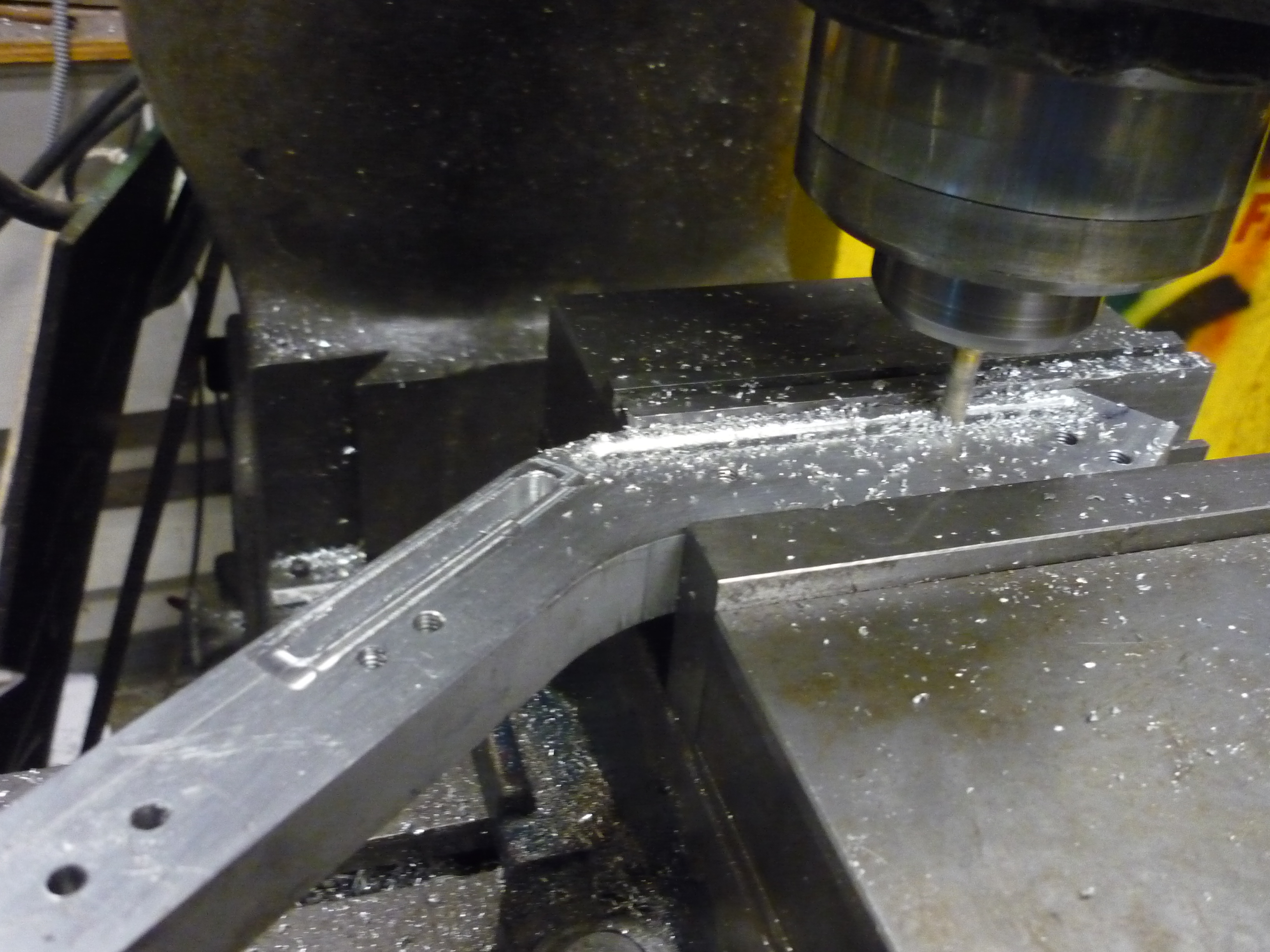 |
 |
| The cable routing inside the swing-arm worked out fairly well, shown far right is the cable sneaking between the swing arm and the controller box. Note this view is from the underside of the skateboard. Look at those sneakily routed wires! | |
 |
| Trials and Tribulations of Torque: So much torque |
| The first 'flight' of the nimbus ended fairly early. A captured nut, linked to the threaded shaft of the motor quickly sheared the threads off the shaft, indicating a far more structural solution would be necessary. To do this, I used a short piece of scrap steel and fashioned a 'clip' that reaches into the slotted portion of the hubmotor assembly and prevents rotation. What I had not accounted for was the enormous lever-arm | 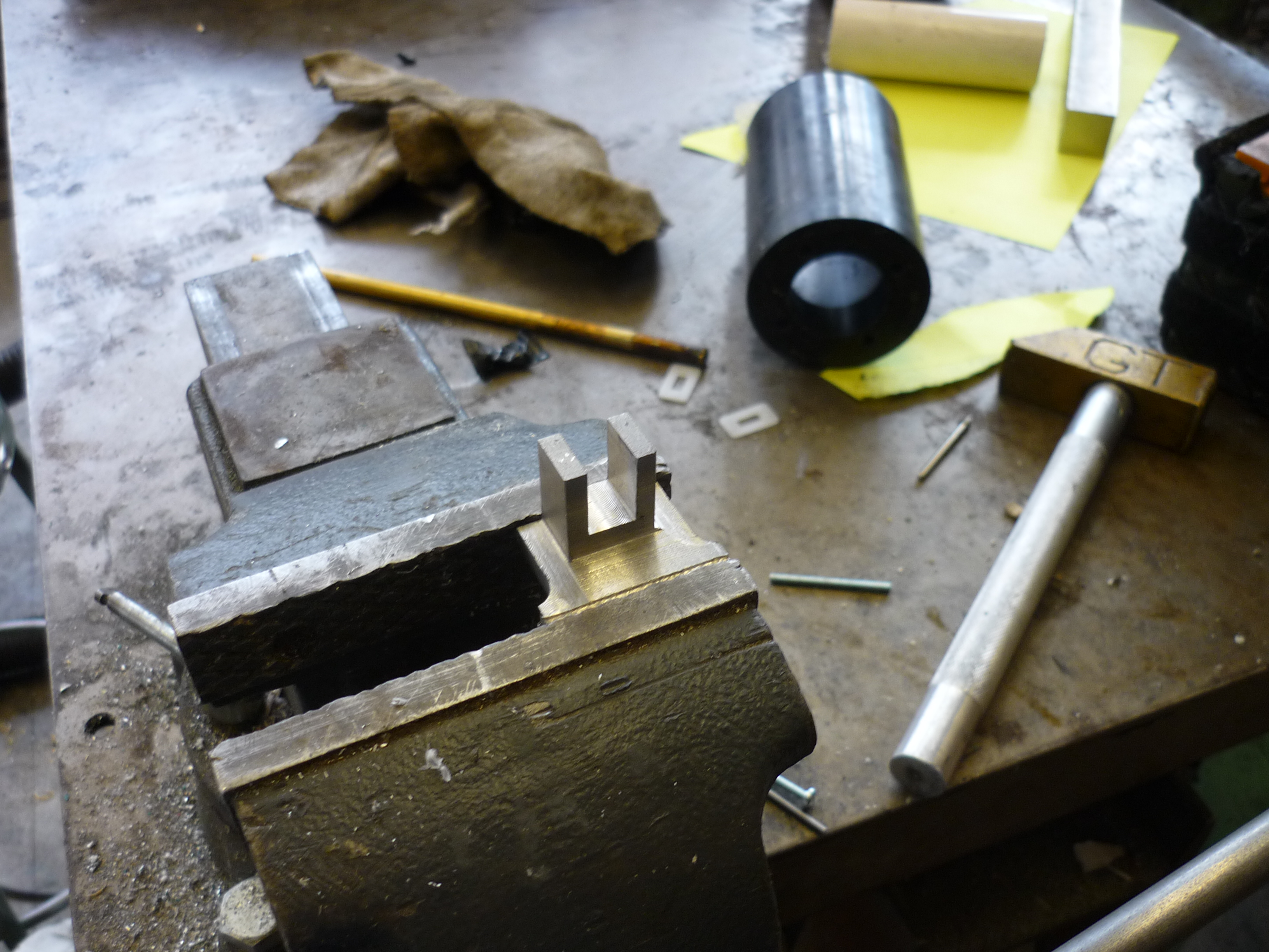 |
 |
| The side of the holster quickly sheared. Even when reinforced by flipping the adapter over to grab the opposing side of the wheel, the adapter had end up rounding the flat-sides of the hub motor. A new approach at mating the motor and frame was required. Time for some solidworks and fluent Finite Element Analysis! |  |
 |
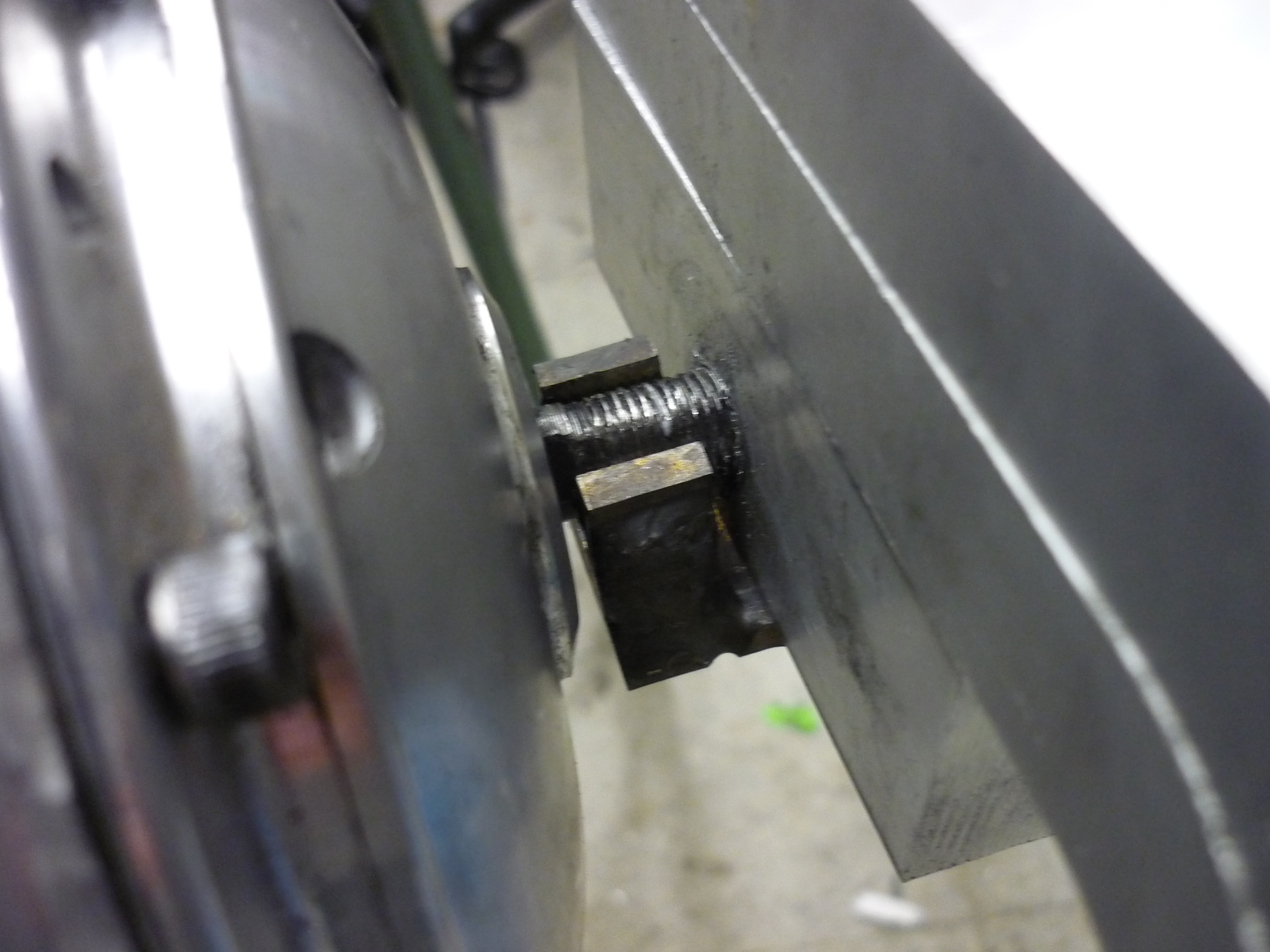
| Shown is the newly weld-reinforced bracket reaching over to the motor and attempting to lock the shaft to the frame, unfortunatley, the lever-arm action quickly rounded the motor shaft and resulted in some twisted wires. | 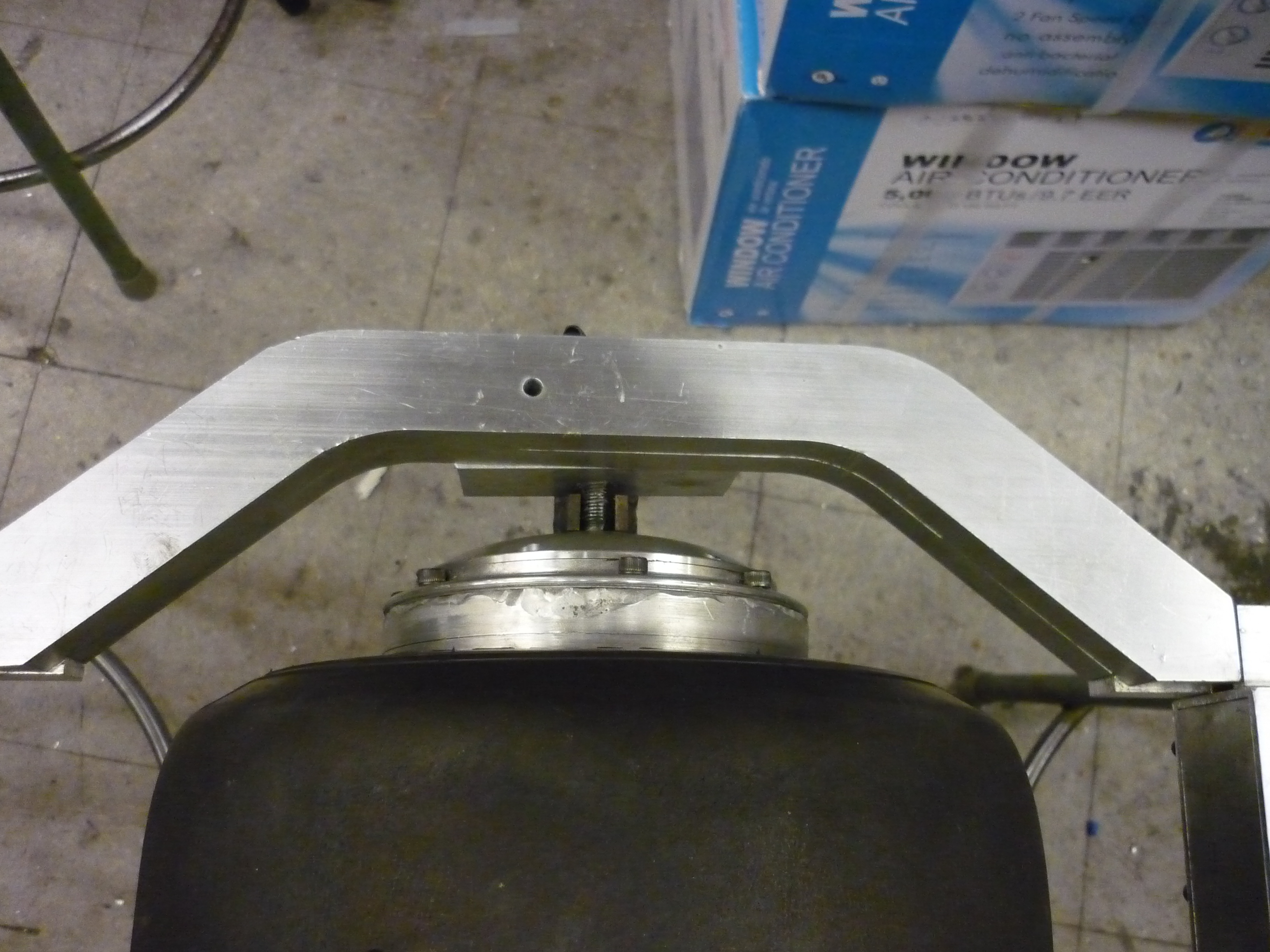 |
 |
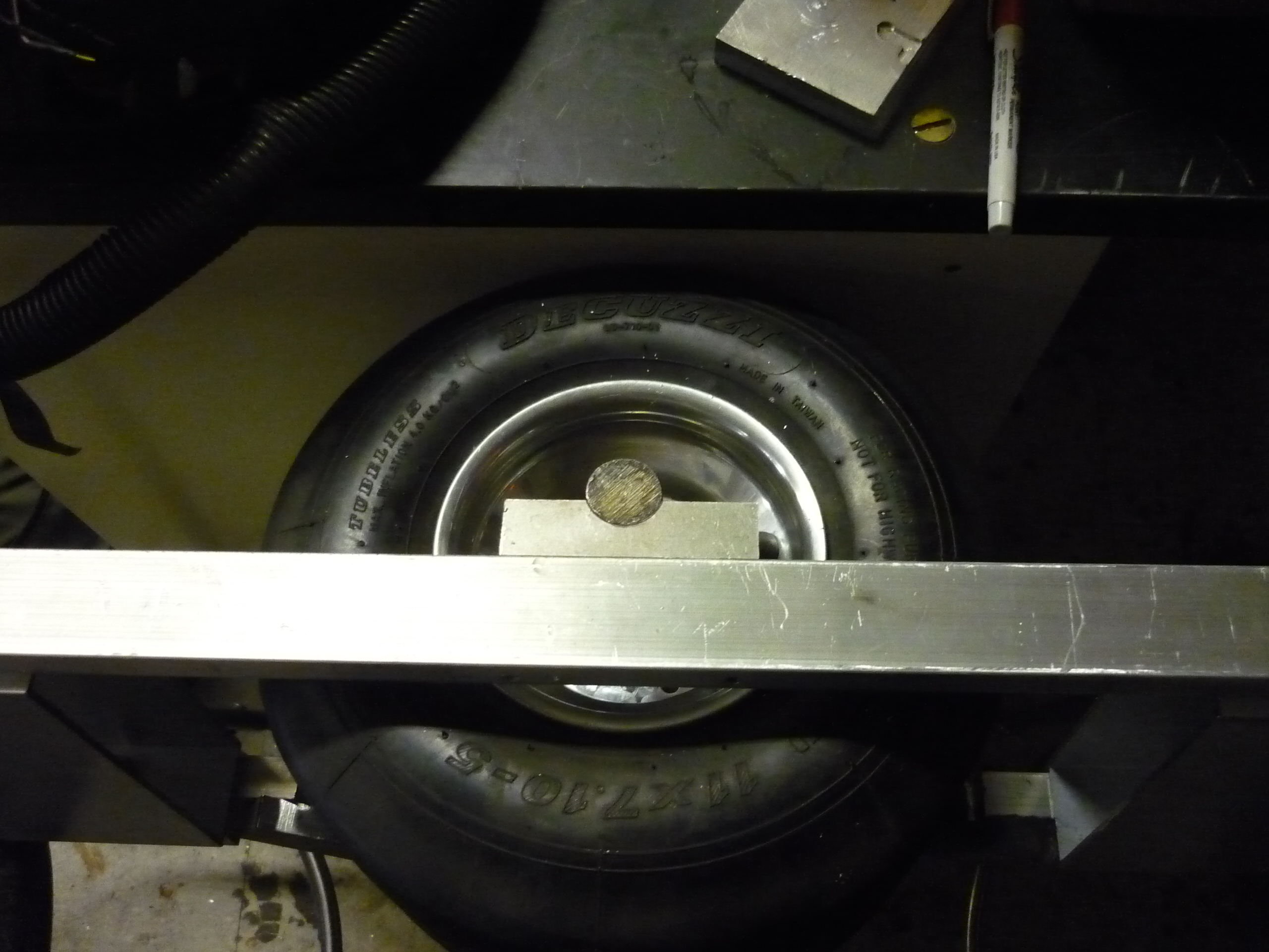
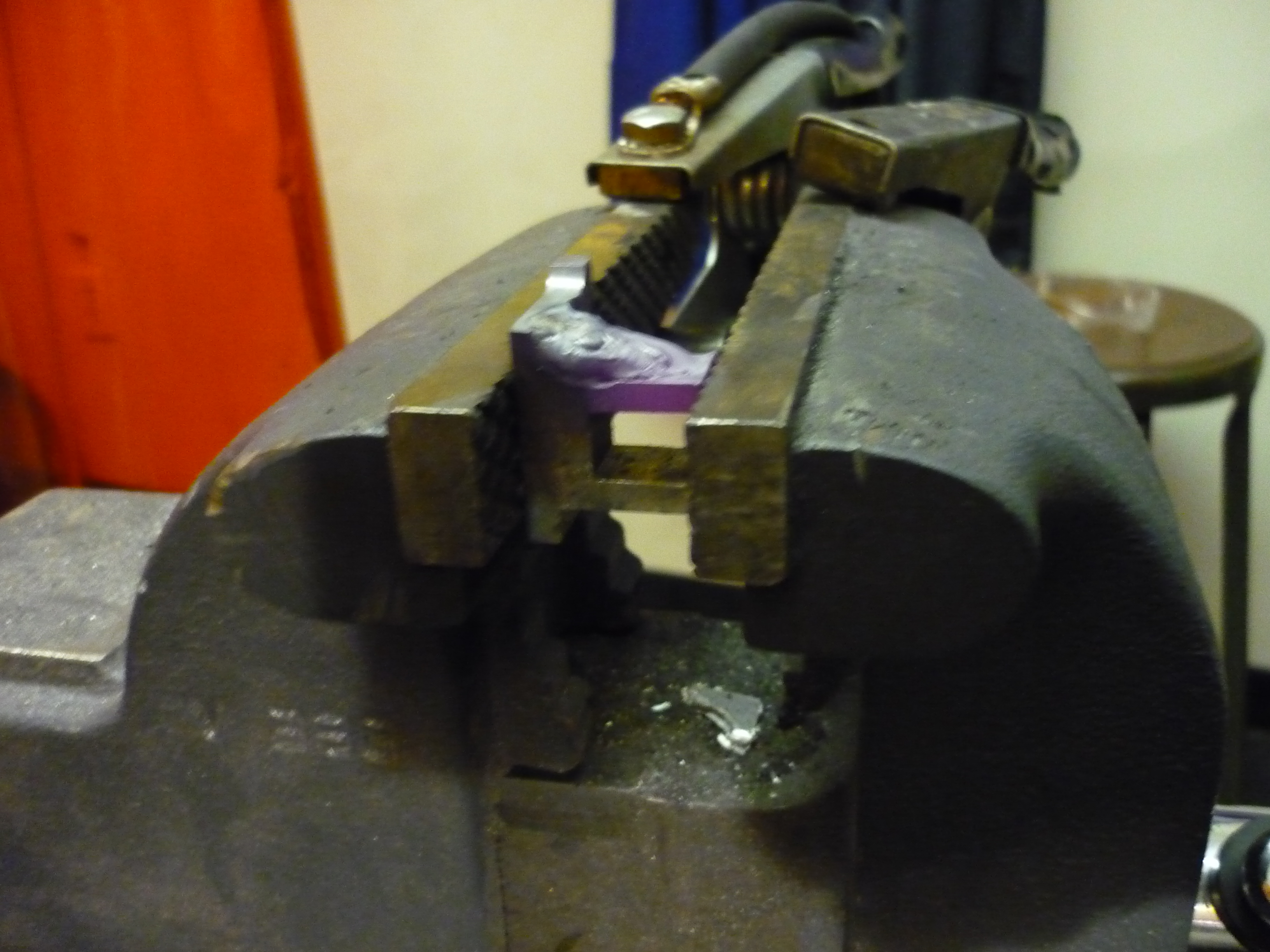
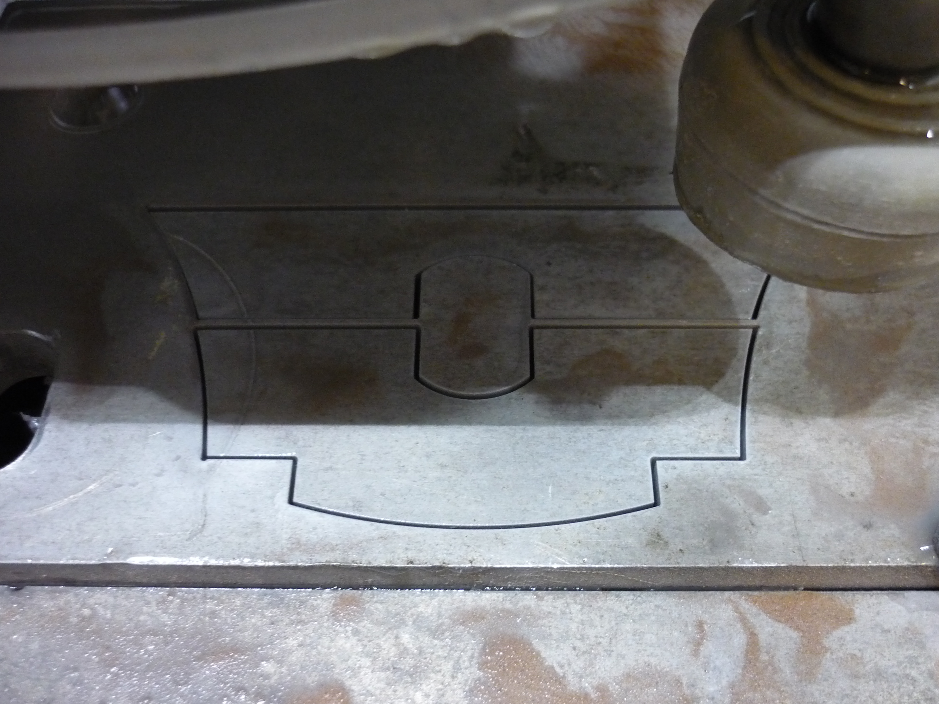
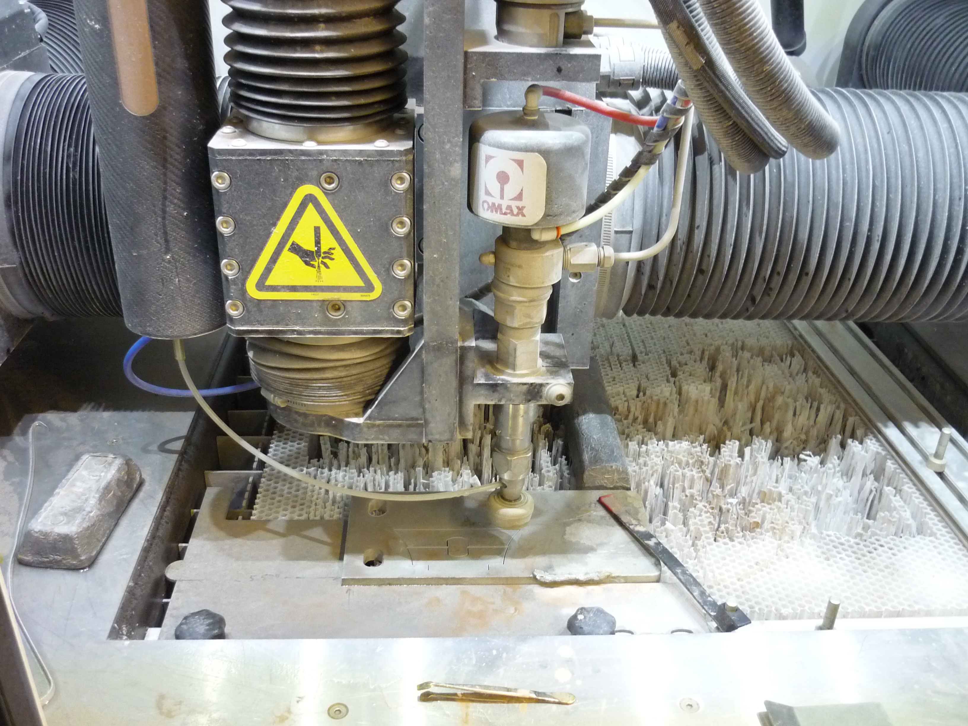
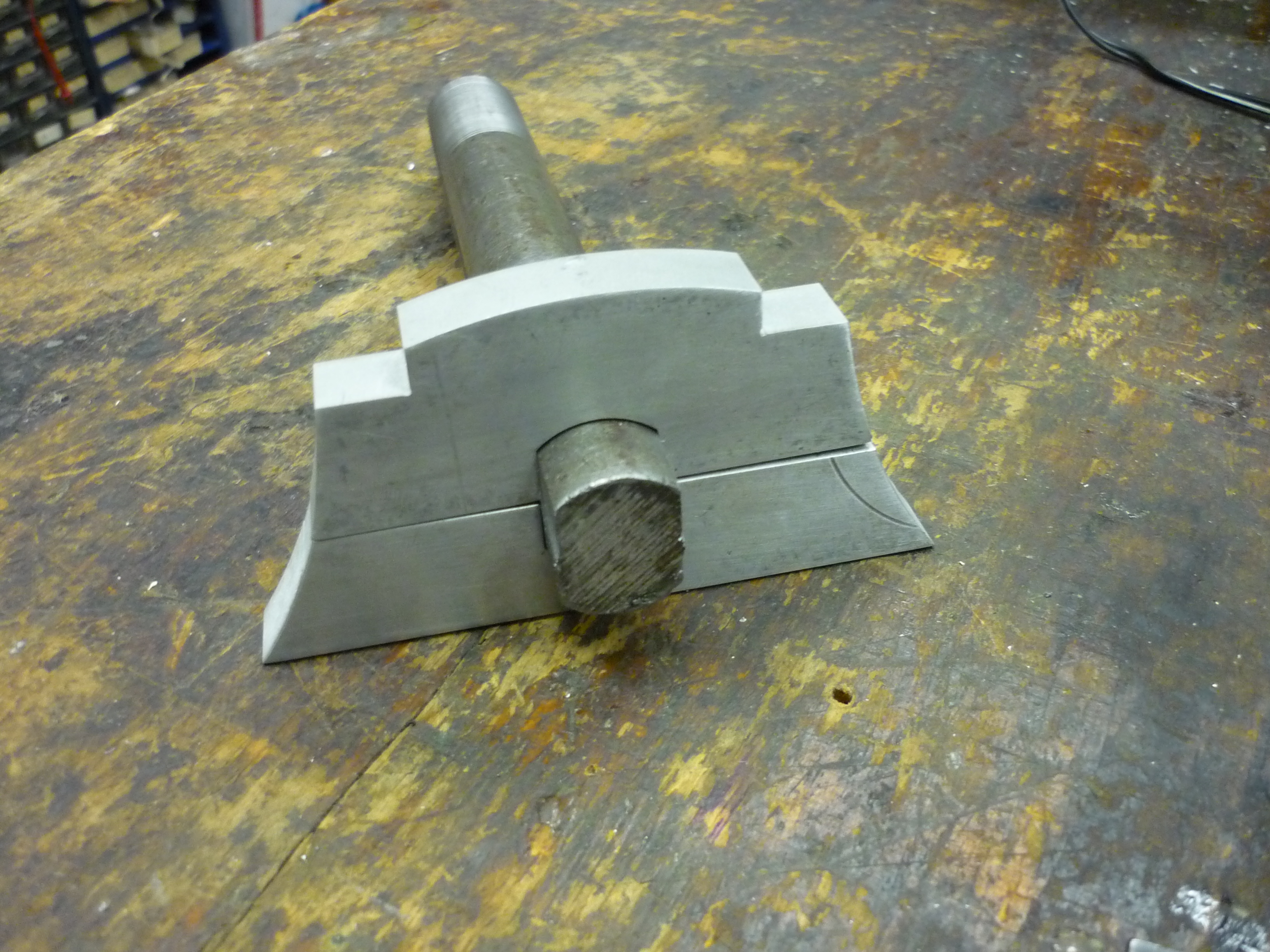
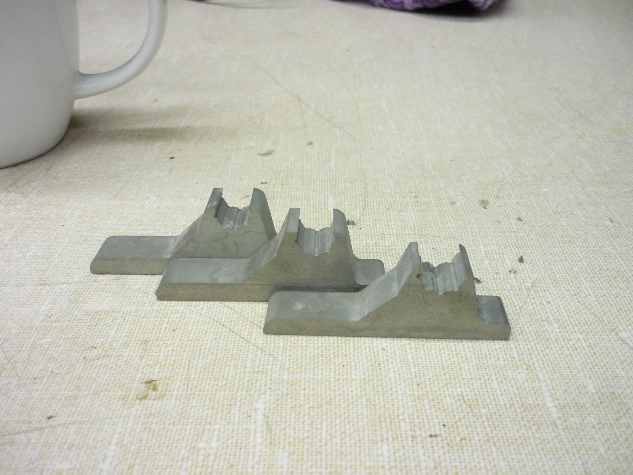
| Fire up the jet! The opposing side of the motor is restrained by a precisely turned-out solid steel rod. Unfortunatley as this is turned out 'round' it is not transfering any motor torque, but meerly holding the motor in place axially. To counter this, I opted to design slotted holsters which can be welded to the steel round. By slotting the steel round on its mating surface to the skateboard, load will be transfered directly to the frame. Unfortunatley here, tolerance is at a premium, slop in the mating surfaces will cause backlash when riding and result in short moment forces which will accelerate mechanical wear. To fix this, a retaining mechanism that couples to the shaft was designed. |
 |
 |
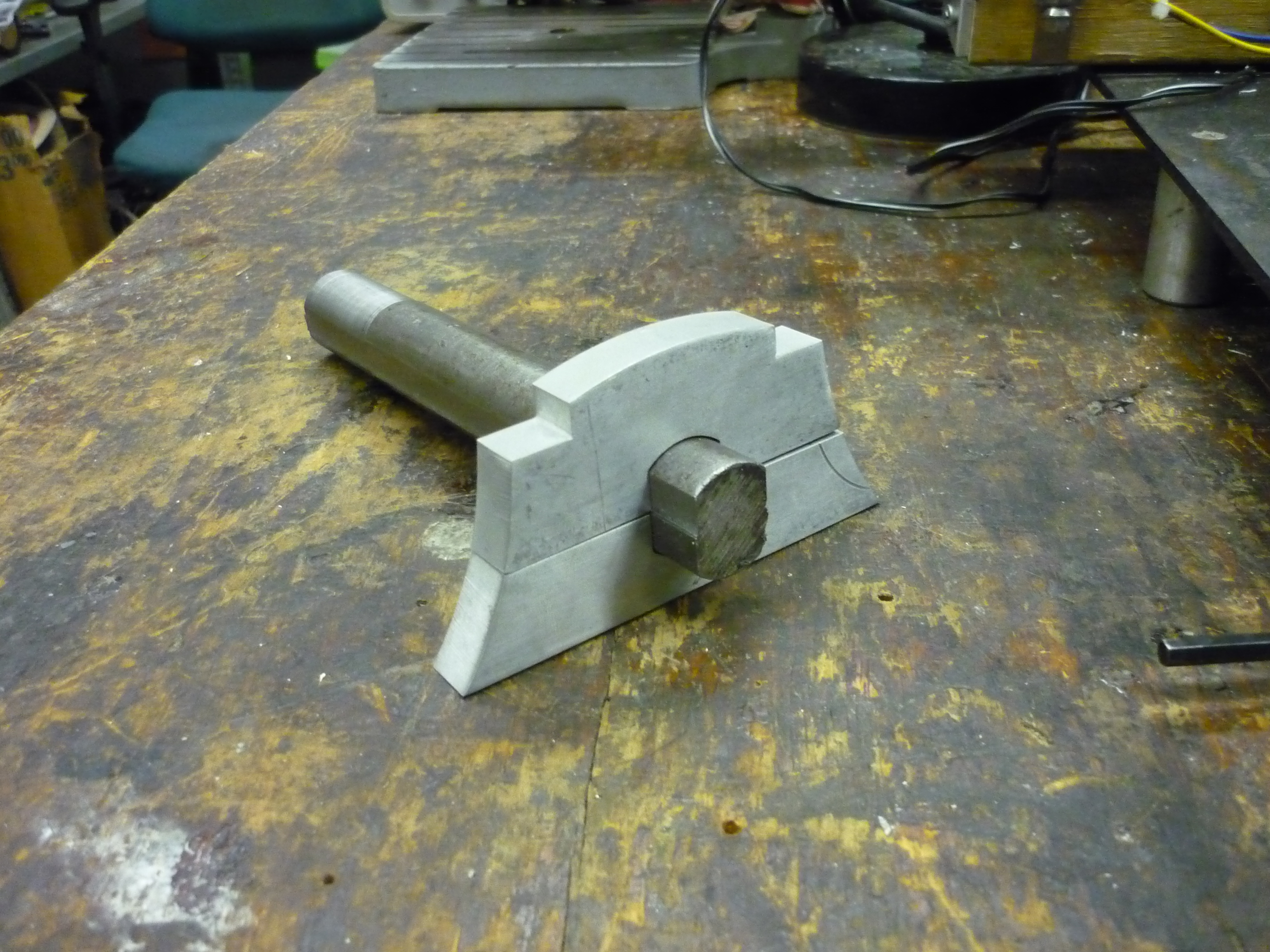
| Shown is the previous holster, clamping to the round, solid retaining rod and the new slotted hoster sitting on top. The indents on the bottom left and right are placeholders for the bolt pattern that mates with the frame. The drafted, swoopy corners are mostly for show. | 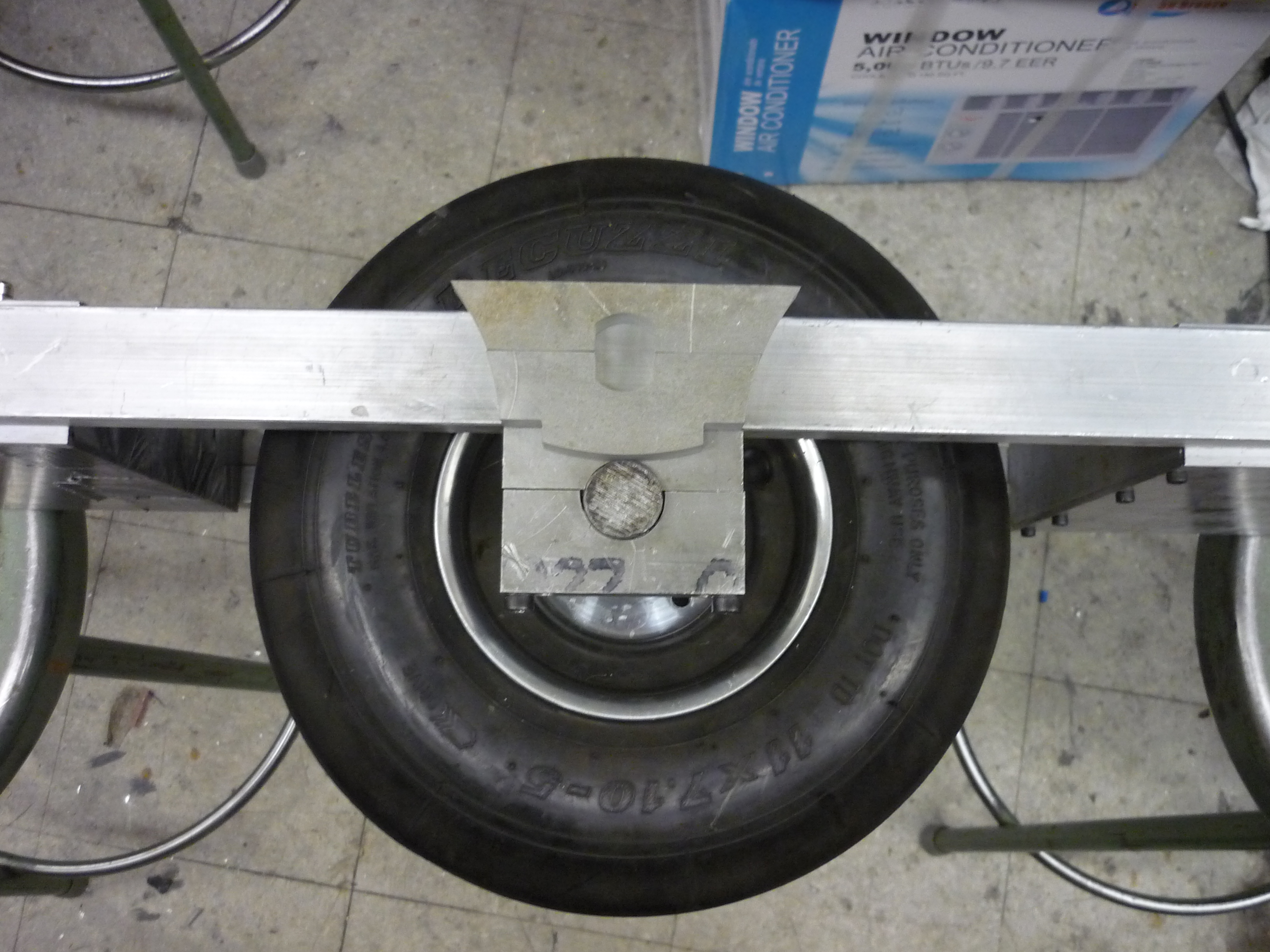 |
 |
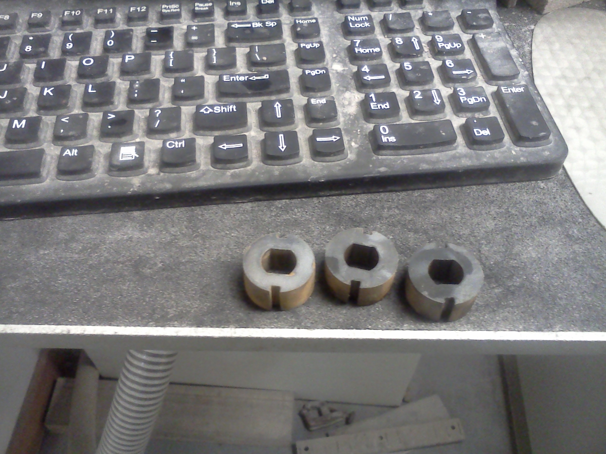
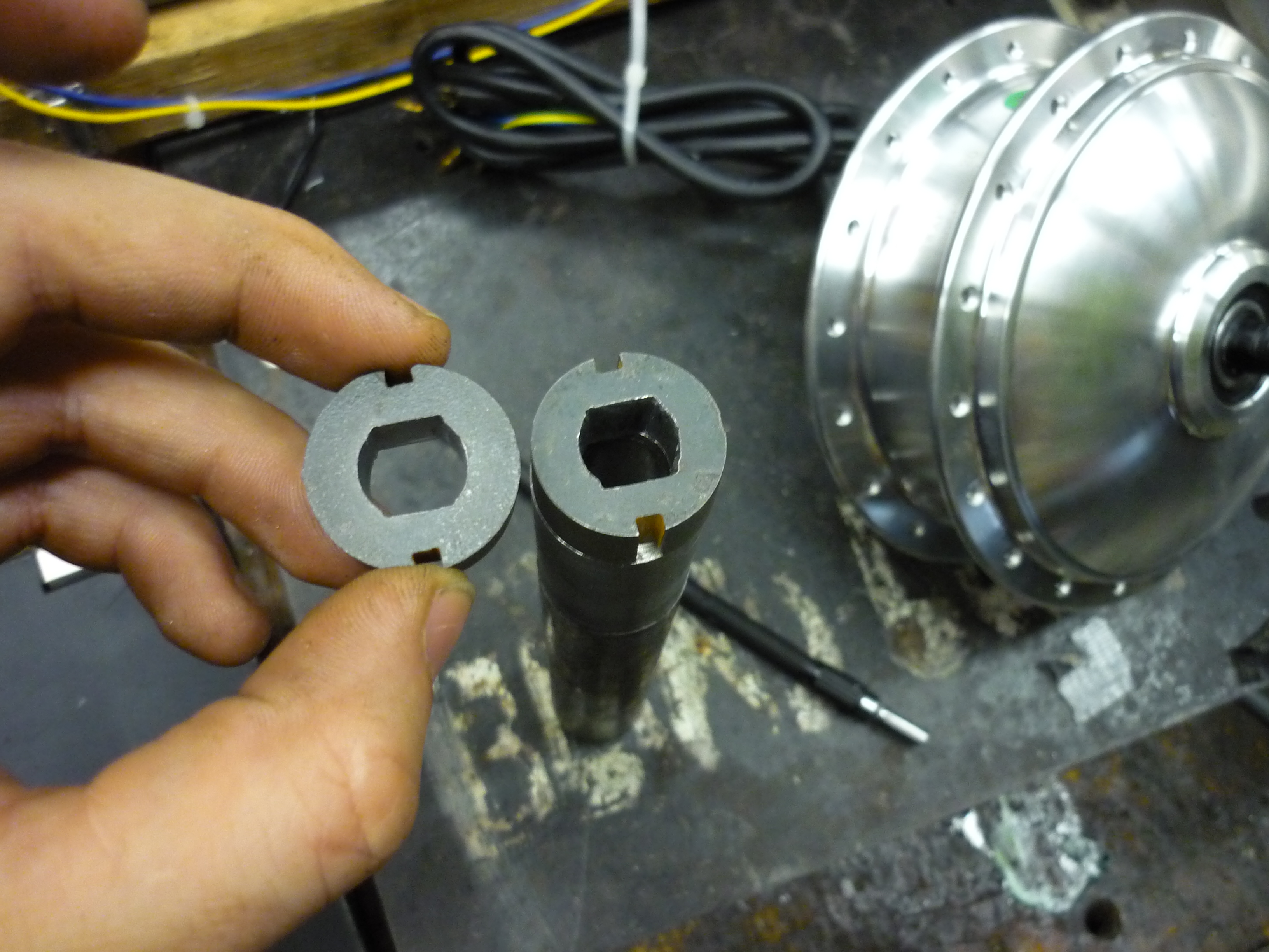
| Torque
transfer adapters Thanks to the ever-awesome A. Grein, some 1/2" steel scrap came my way, which quickly turned into these lovely 'slotted shaft to round' adapters. The idea here is to increase the transfer area from the slotted motor shaft, out to the frame. There was an additional square bracket to cut out, but unfortunatley the scrap shifted a bit during the cut. The insides of the axle adapters were filed profusely to get just the right fit. |
 |
 |
| These mate to the shaft of the motor and will eventiually get welded to the opposing axle. This should increase the load transfer capability of the motor-to-frame moment force that sheared the mount earlier on. |  |
 |
| After welding (there was a lot of welding) I used the bridgeport milling machine to slot the axle shaft holster to match with the frame mount. The two indents (shown on the top of the cutout part) are spaced for two M6 Mounting bolts. The notch constrains the shaft for torsional loads and also prevents axial loads as the milled portion of the shaft ends right behind the plate. | |
 |
| Shaft bushing to provide the correct spacing from the swingarm to the motor mount, I machined a bushing. When fully assembled this prevents axial sliding of the motor. |
 |
 |
| Putting it all together Who said there's a limit to the number of setscrews you can use? Shown is the (messy) tog welded slotted shaft mate and 8 setscrews to restrain the axle shaft and transfer torque to the frame. |
 |
 |
| Control Theory | |
| To keep the balancing skateboard pointing the right way up, an accelerometer and rate-gyro are used. Why both? For a balancing craft the only relevant variable is angle, how many degrees from horizontal. So why not just use an accelerometer? A three axis accelerometer could very eaisly accertain its relative angle to horizontal, in a static environment, however, on a moving craft, the accelerometer can not assertain the differnece between craft acceleration and gravity, to get around this shortcoming, a rate-gyro is used. Rate-gyro? Gyro ic's are fairly far seperated from their spinning electromechanical bretheren, the output is the effectve change in degrees per unit time, or degrees/second. Integrating the degrees/second provides degrees, however, any offset at the initial integration (if the gyro is not zero'd) will integrate in and provide an innacturate angle estimate. So rate-gyro-error starts climbing over long periods of time, but provides a fairly good short term angle estimate, while accelerometers provide a decent average angle over long periods of time. | |
| Mix and mash Each sensor has an advantage and a disadvantage, proportionatley mixing the high-frequency portion of the rate-gyro and the low-frequency portion of the accelerometer provides a relativley stable angle measurement in relation to the horizontal. |
|
| Angles and balance With a known angle in relation to the horizontal, a mechanism to have the motor drive compensate for changes in angle is needed. The simplest method would be block commutation: If relative angle to horizontal is less than x reverse the motor drive, If relative angle to horizontal is greater than x, set the motor drive forward. This gets a bit intense, as the platform would wildly swing back and forth between full forward and full reverse, waste quite a bit of energy and be relativley un-manageable. A plot of the stability of this type of control is shown right. |
|
| PID happiness One of the most common ways to stabilize a system is a PID control loop. Implementing PID [wikipedia link], is fairly straightforward. The motor speed output is relative to the vehicle's angle in relation to the ground, its proprotional and derivitave gain value.
|
|
| More info: Checkout shane's seg-stick instructable [link] Jordan's seg-board page [link] and charles's seg-fault writeup [link] they are a great background in all things balancing. |
| Tweaks and First Flight |
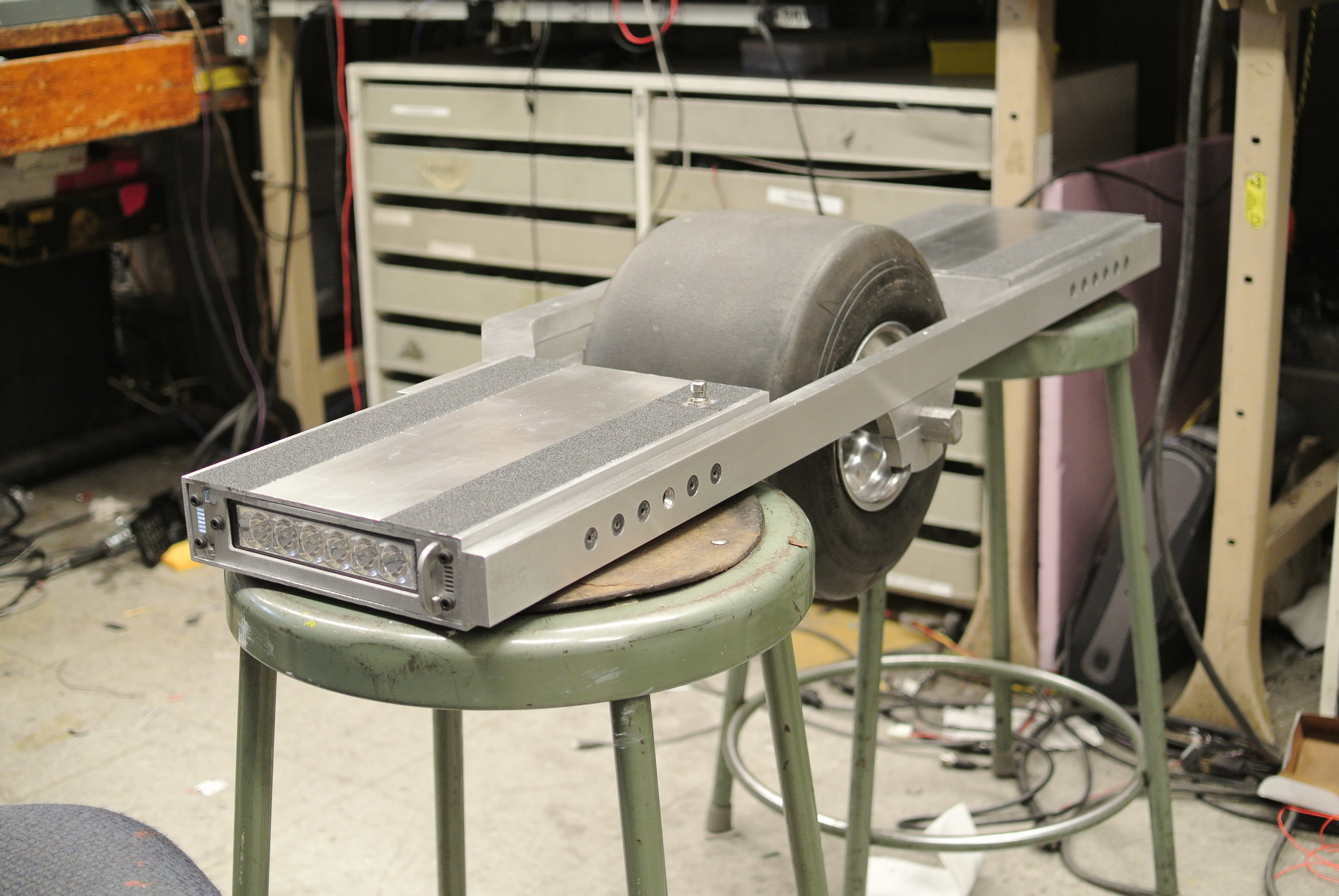
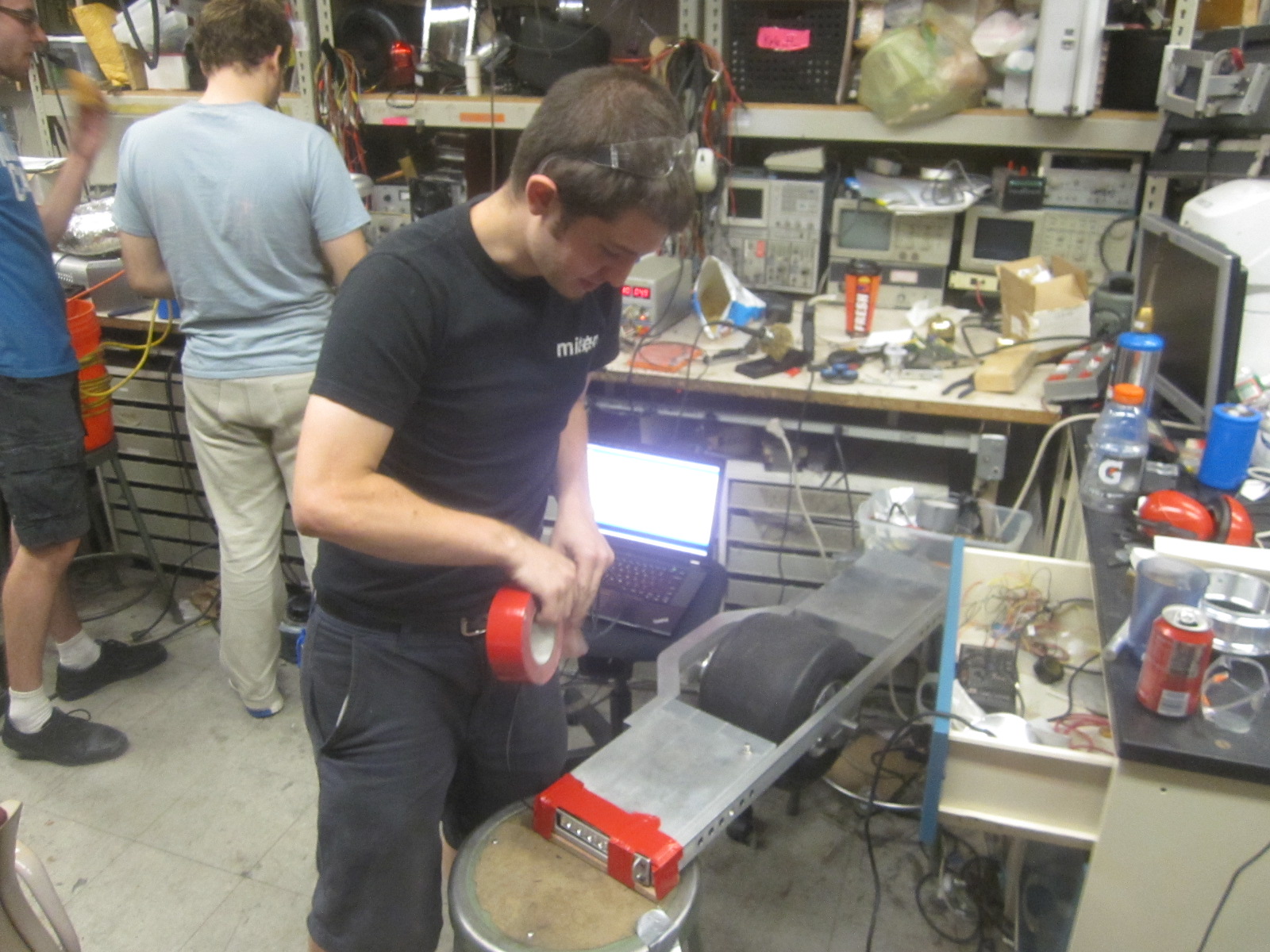
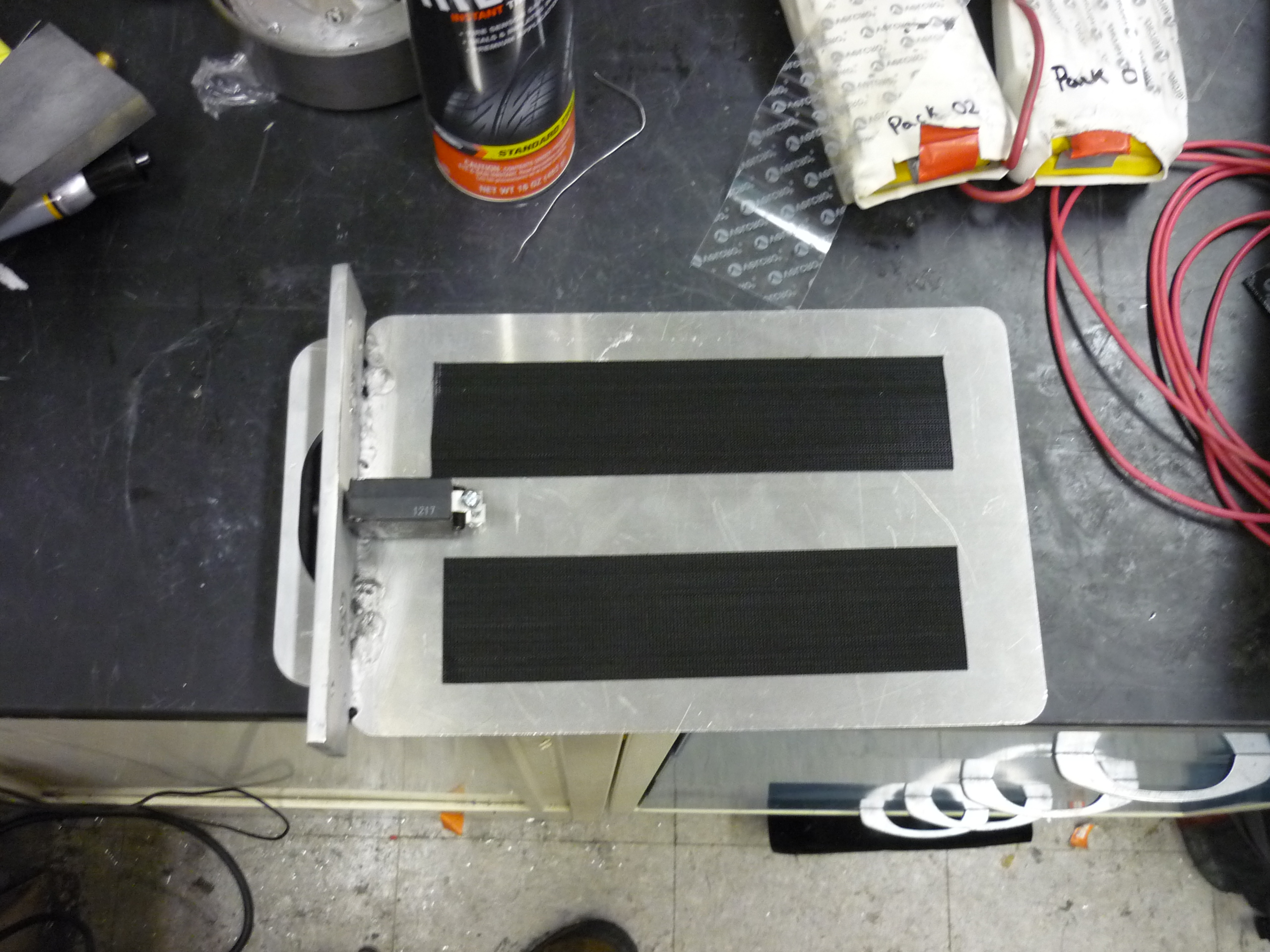
| Before launch I added two strips of 3" wide abrasive grip-tape [amazon link] and used a metal sanding block to clean up the surface of the frame. Over the previous 2 weeks of tinkering, there were a number of gouges, oil smears and miters-grime that had built up. |
 |
 |
| A 12v led strip was added to the motor control board to indicate that 12v power was available and the hardware was online and running, for affed effect, I placed the led strip near the fan/cooling vents to provide a display of internal glow. At the moment there's no diffuser so the strip can be viewed through the slats, in a future update diffusion will be added to make a more uniform glow. |  |
 |
| War Wounds The first ride provided some quick indghts as to what worked and what needed improvement. It turned out the gasket-seal setup that held in the motor controller 'drawer' needed a bit of redesign. Shock loads (from slamming the front into the ground) would cause the craft to kick out the drawer setup after repeated slams. To combat this short term, red gaffers tape is used. A number of 'bumper' setups were hypothesized, ranging from wheels to bearings to consumable materials to protect the sides. During testing the battery bay handle, mounted to a polycarbonate sheet, sheared off. Shown, far right is the pack recharging in the warm clutches of a hyperion 1420i. |
 |
 |
Observations and improvements
|
 |
   |
| First Flight: Trust the Machine | Image / Media | |
Ideas from first
round of testing
|
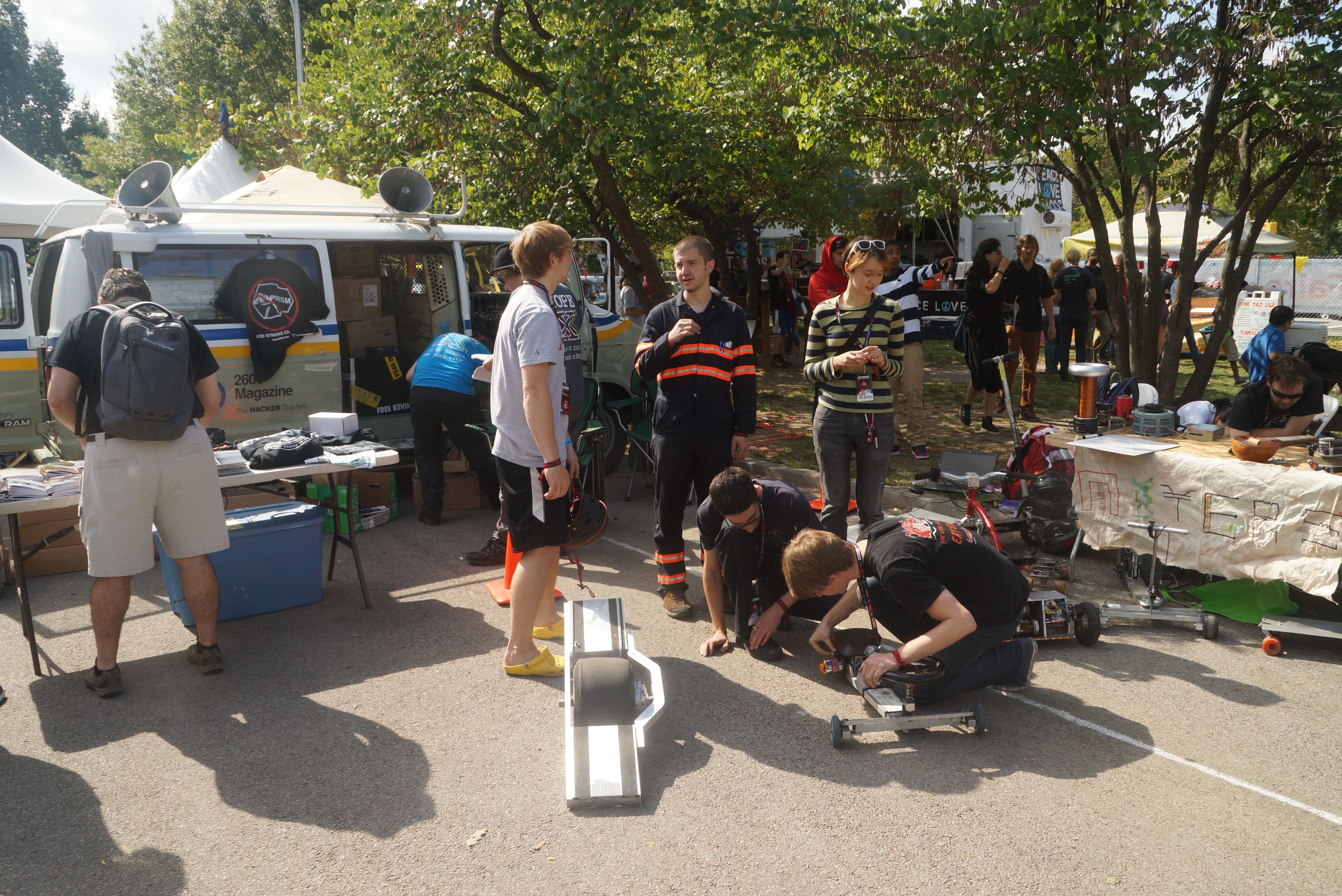
| Makerfaire NYC 2014 |
| The nimbus, amidst upgrades, made it to the NYC makerfaire 2014. A number of people asked questions about how it worked, what it ran on and everything in between. There were a lot of suprisingly technical questions and a few 'can I buy that' queries. I handed out a flyer [PDF flyer] with details and a link to this page to try and convince folk to build a derivative of their own. | |
 |
| I used the nimbus during a power-wheels-racing event. While I didnt let any non-wristbanded people ride around (red-wristbands = signed injury waiver), some miters-folk and PowerWheels racing comrades gave it a go. |  |
 |
| ITS HEAVY The nimbus, like almost every other contraption i've made, is a bit of a pain to carry around. Instead I opted to surf through the crouds, making 'beep beep' noises when people got in the way. A few really young kids crowded around asking questions as I hovered near them and two or so gave me high-fives. That was absolutley the highlight of the day. |
 |
 |
| The miters table The nimbus spent most of the day sitting next to the miters table, along with a pile of other contraptions. Nancy defended the table from the inbound onslaught of interested new yorkers. |
 |
 |
| Post NYC Makerfaire Upgrades |
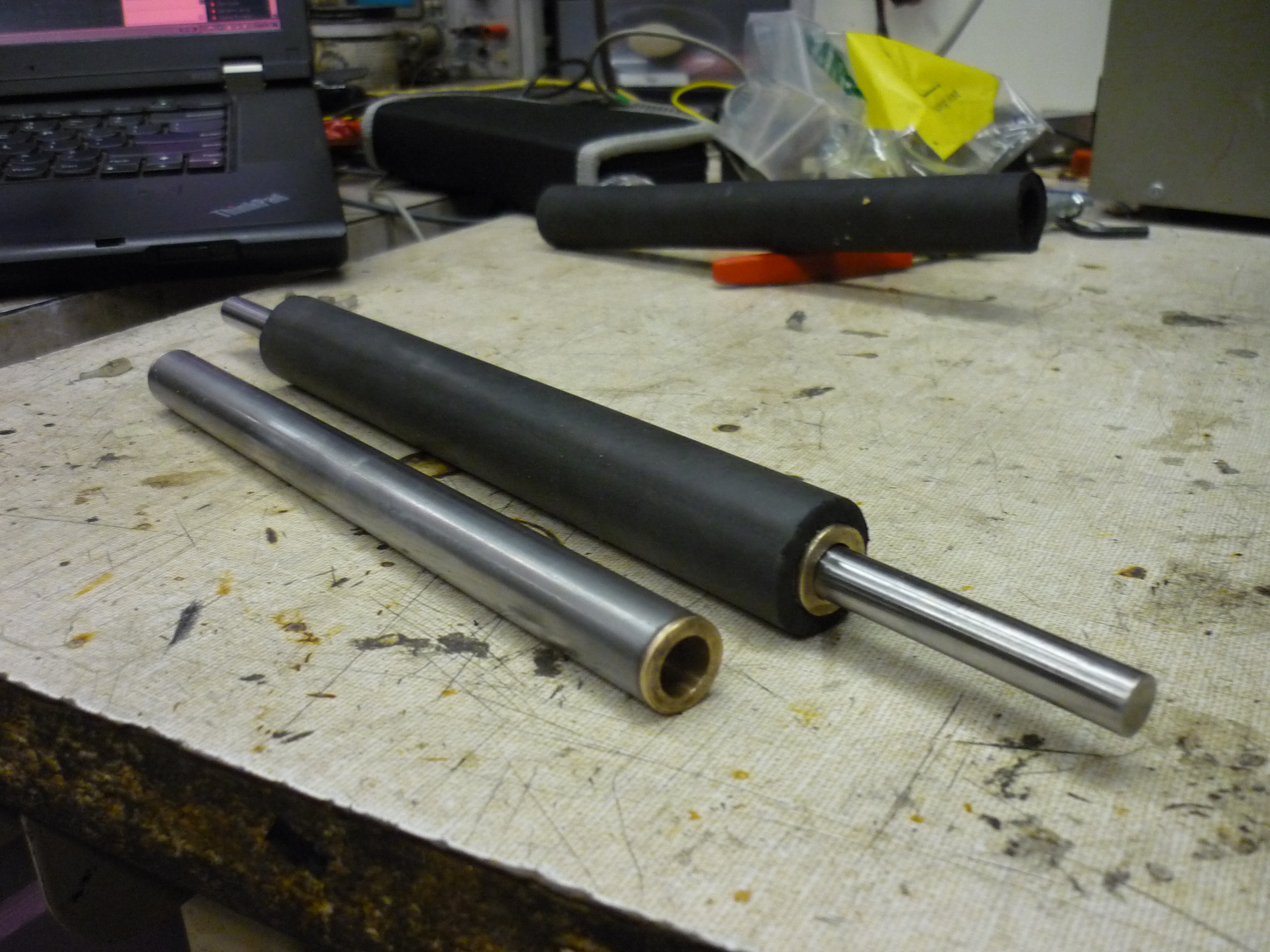
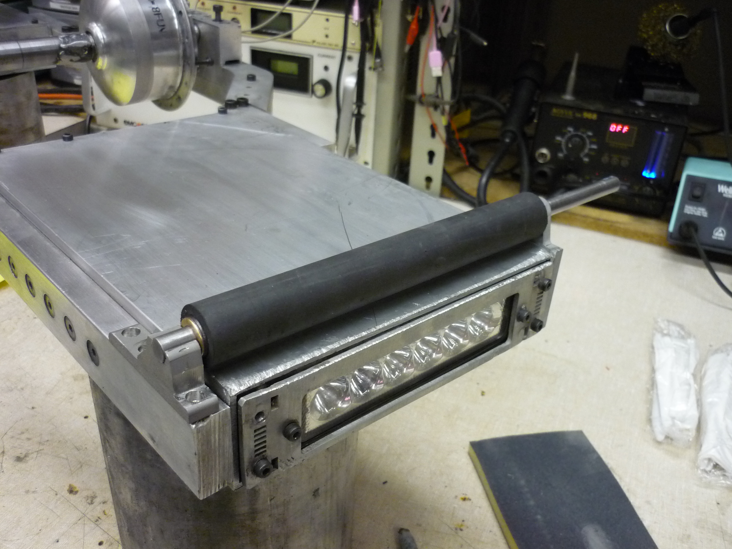
| Training Wheels! one of the biggest issues at the NYC makerfaire was dinging-up the corners of the skateboard. To counter this, i devised a swanky, low-profile roller wheel. The roller consists of a steel tube, two brass bushings, a ground rod and some low-durometer rubber tubing. Shown (right) is the roller with / without the rubber tubing. |
 |
 |
| Mating it to the
frame To mate the roller to the frame, I needed something that could take the shock-loads of a 'faceplant' style incident. Some 3/8" stainless-steel plate was used. The plate was cut to allow the shaft to loosely fit, and have cavities to mate the two together with weld. I made 3 as TIG welding steel-to-stainless was something I hadn't tried before. |
 |
 |
| A mockup Using some clamps I put together a mock-up of what the whole setup would look like. I didnt want the roller assembly to look goofy and stick out too far, but in the opposite sense, I also did not want an ultra-tiny roller which wouldnt be able to handle bumpy terrain. |
 |
 |
| Mockup -> Real A welded, bolted in place roller assembly comes together! shown far right is the completed roller, sitting underneath the battery tray. |
 |
 |
| More weld The rim also suffered some damage. For asthetic reasons a majority of the rim was turned down to have a flat finish, unfortunatley this ate away at a large amount of the rim's structrual integrity. During the makerfaire it cracked along one of the rim-spacer seams. This time i opted for 'a pile of weld' |
 |
 |
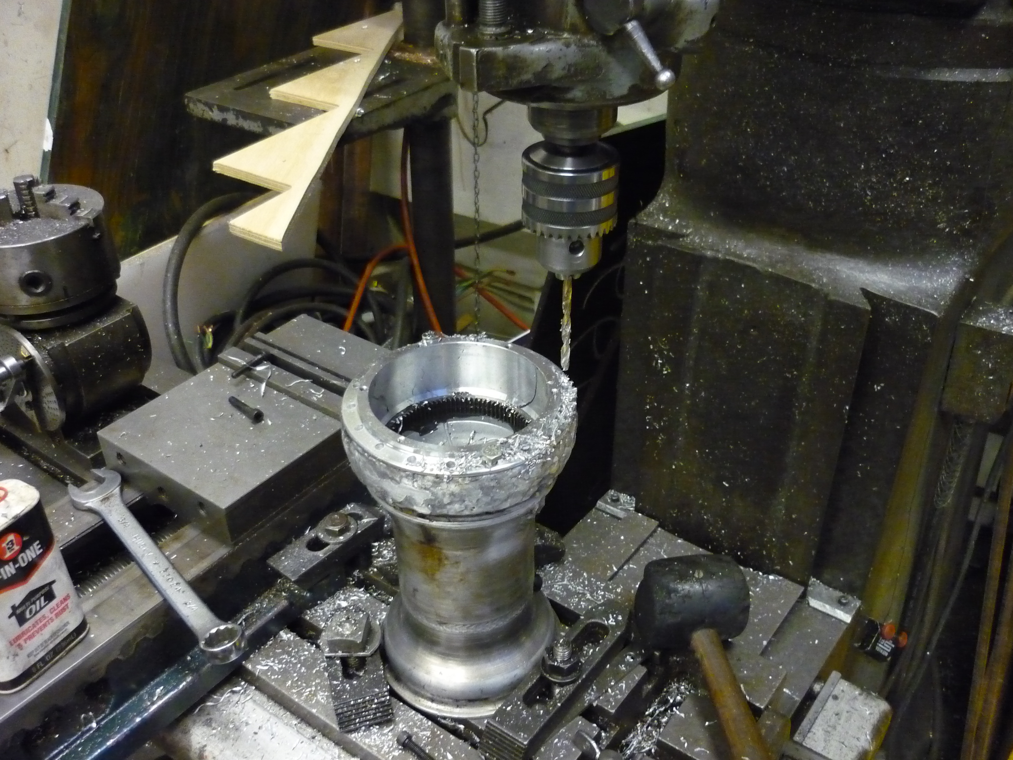
| More bolt holes I also increased the number of bolt holes (between the hub motor and the rim) shown far right, a bridgeport mill is being used for precise-height drilling. |
 |
 |
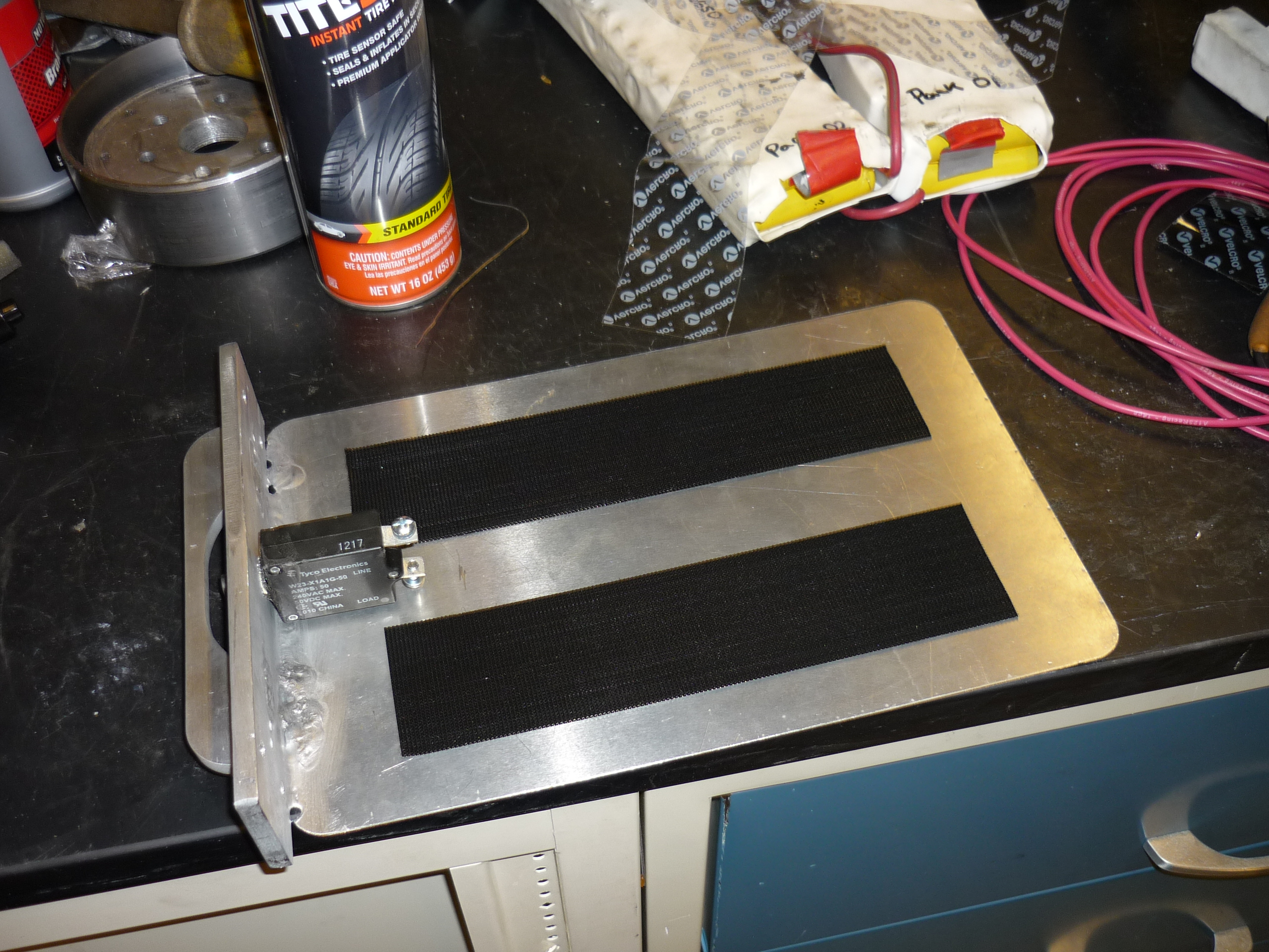
| Updated Battery
tray The previous battery box topology wasnt working well, so a thin plate, tig welded to a handle assembly was born. A 50A dc circuit breaker is shown in the middle, using the handle as a button protector. Velcro is used to keep the batteries in place. A thumbscrew grabbs the pack from the side to keep it in place. |
 |
 |
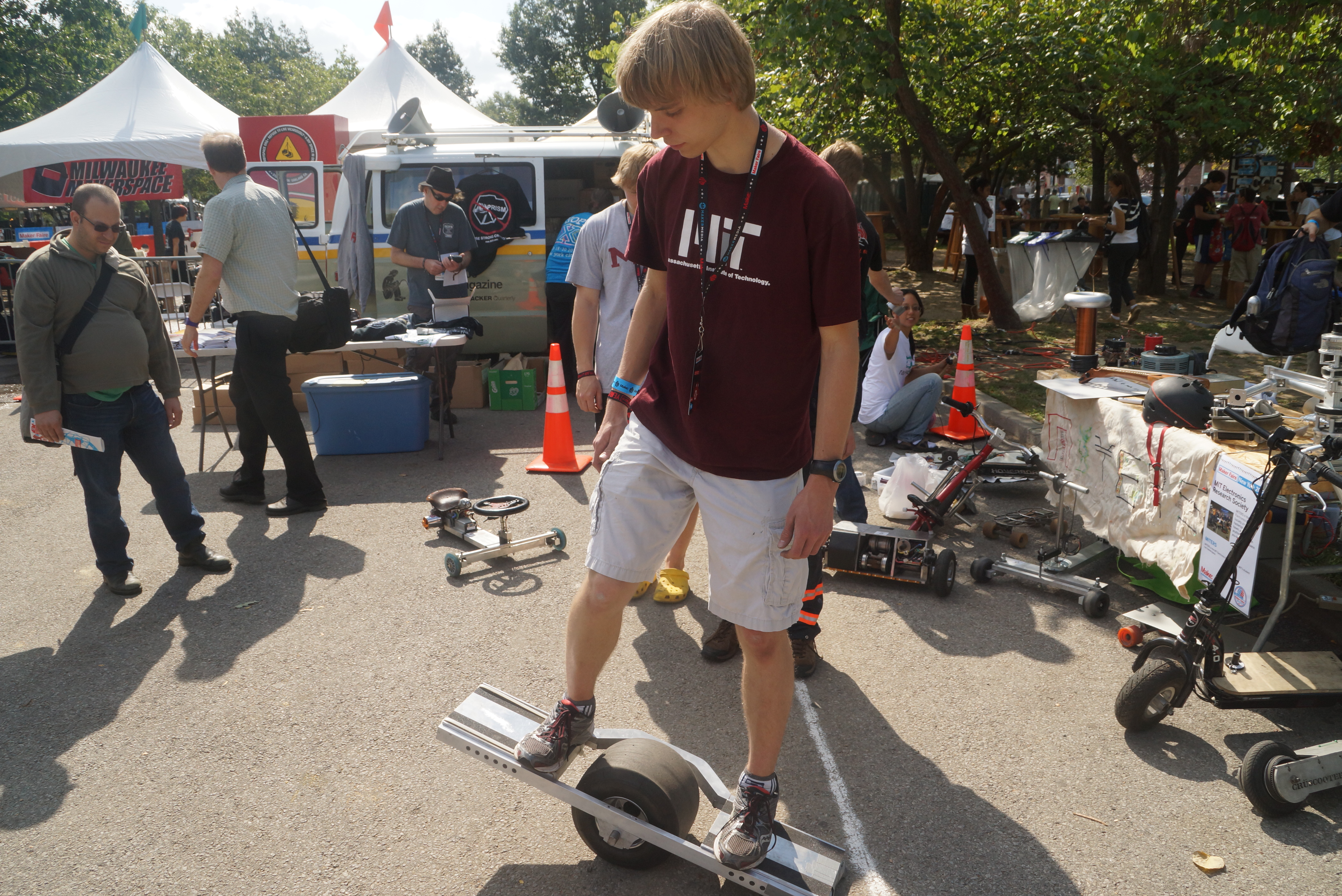
| Makerfaire MIT 2014 | ||
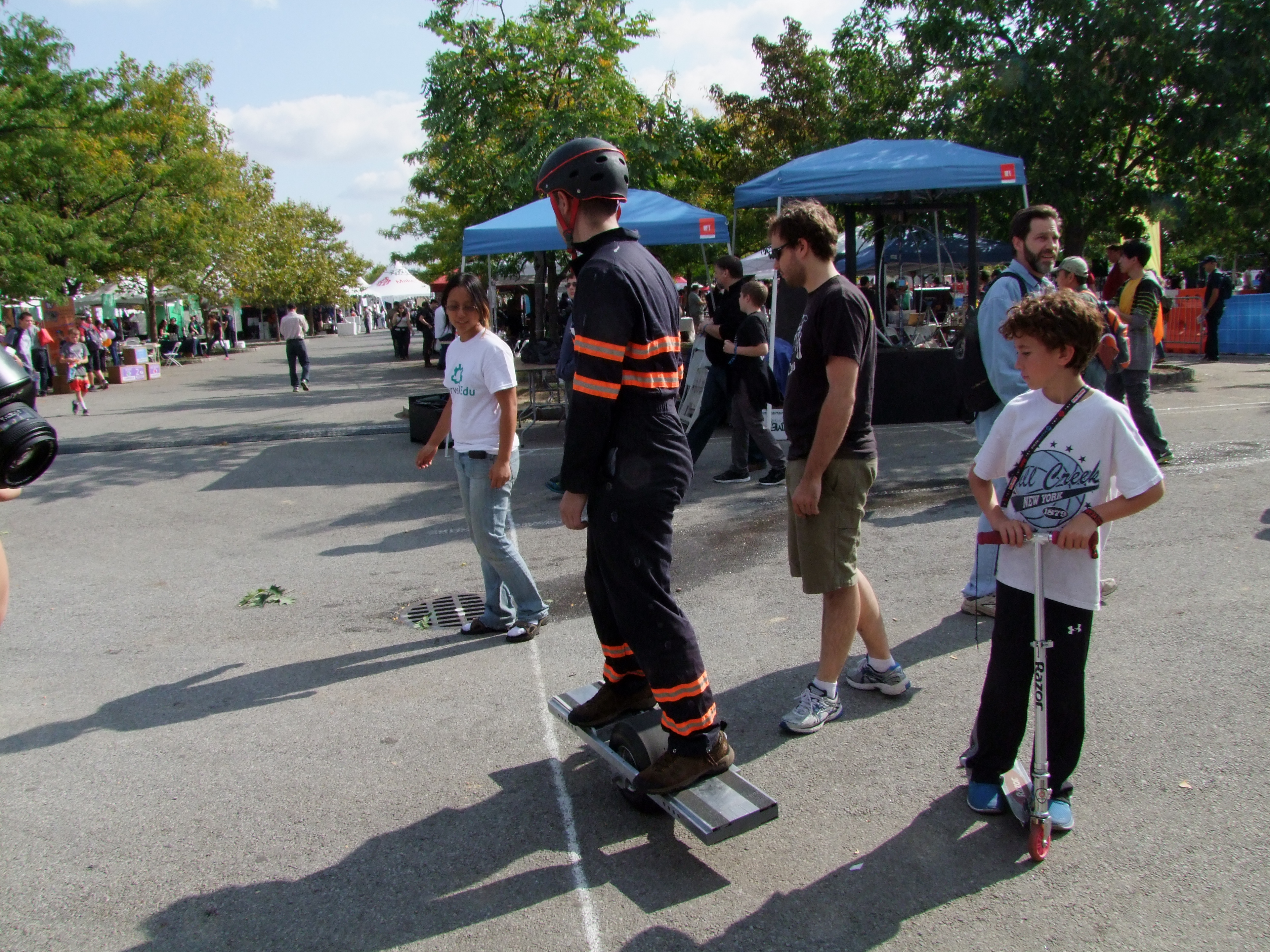
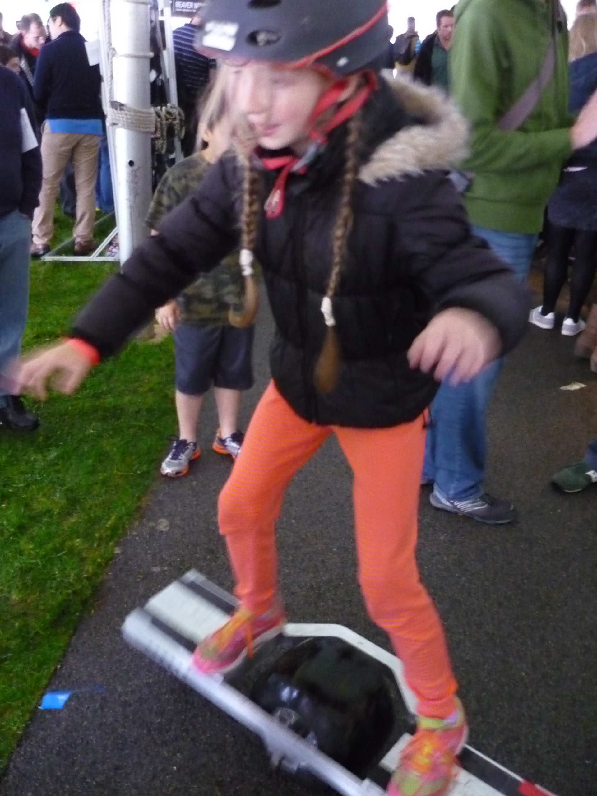
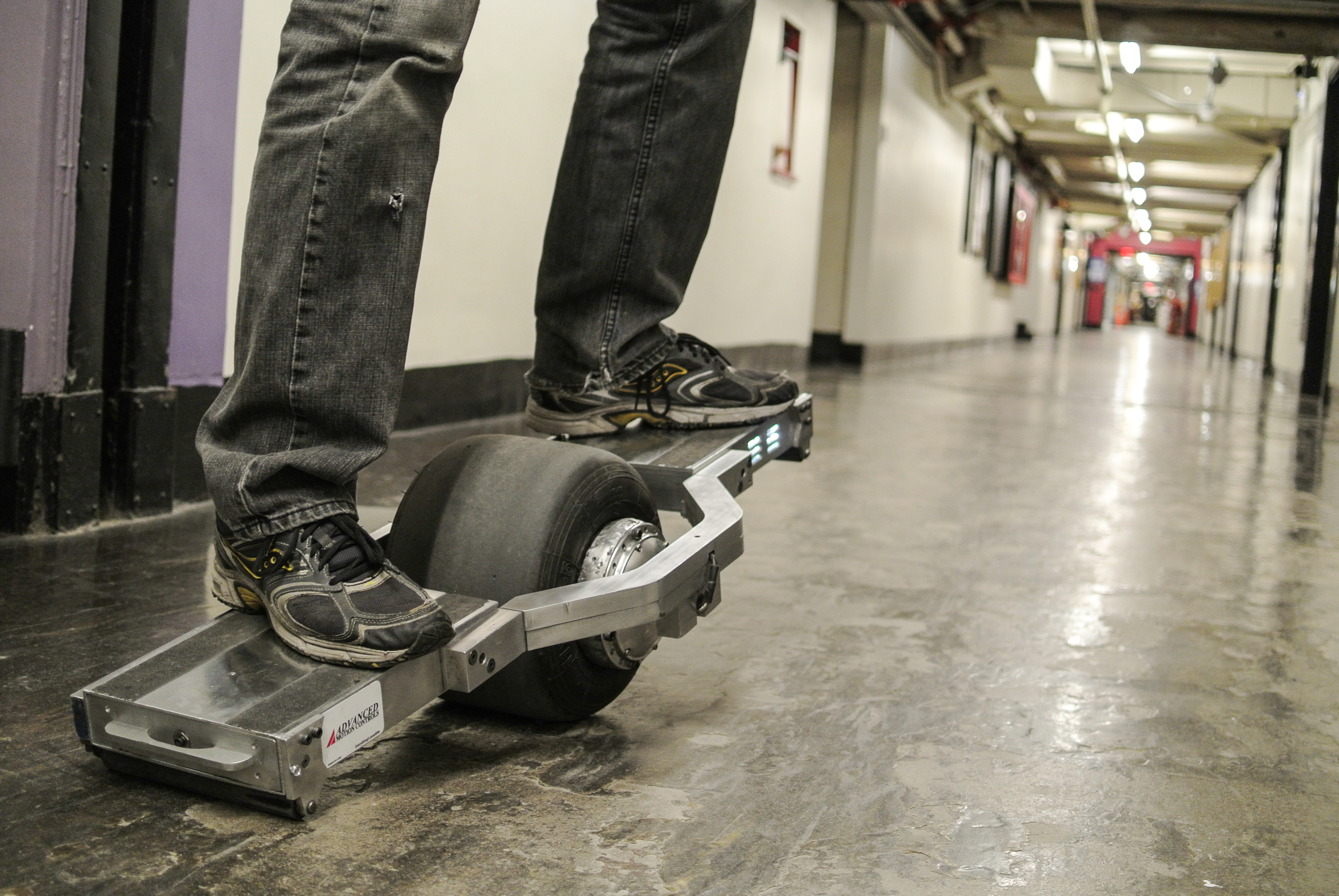
| MIT MAKERFAIRE WAS A BLAST There was a huge number of people who turned out for the fair. Families, children and wayward professors wandered around amongst tables of contraptions. A pile of people asked questions about the skateboard. I ended up providing demos, then handing over control to many red-wristbanded (waiver = signed) folk. Children, adults (I need to impose a max weight limit, see aftermath below) and everyone inbetween gave it a go. A number of people snuck back to give it a try a second time. [left photo by link] |
 |
 |
| I ended up handing over my helmet to EVERYONE, after a quick tutorial and some hand-holding. People started with balancing and even zooming away at high speeds. Far right is Josh (muffinator) Gordonson. One interesting observation was that folks with tall-fancy-shoes had an instantaneous nack for riding about. They do have a lot more balancing practice than us sneaker-wearing folk. |  |
 |
| There were also a number of small test pilots. Yes, even Cambridge PD gave it a go. This kid re-appeared every 45 minutes to test it out. | 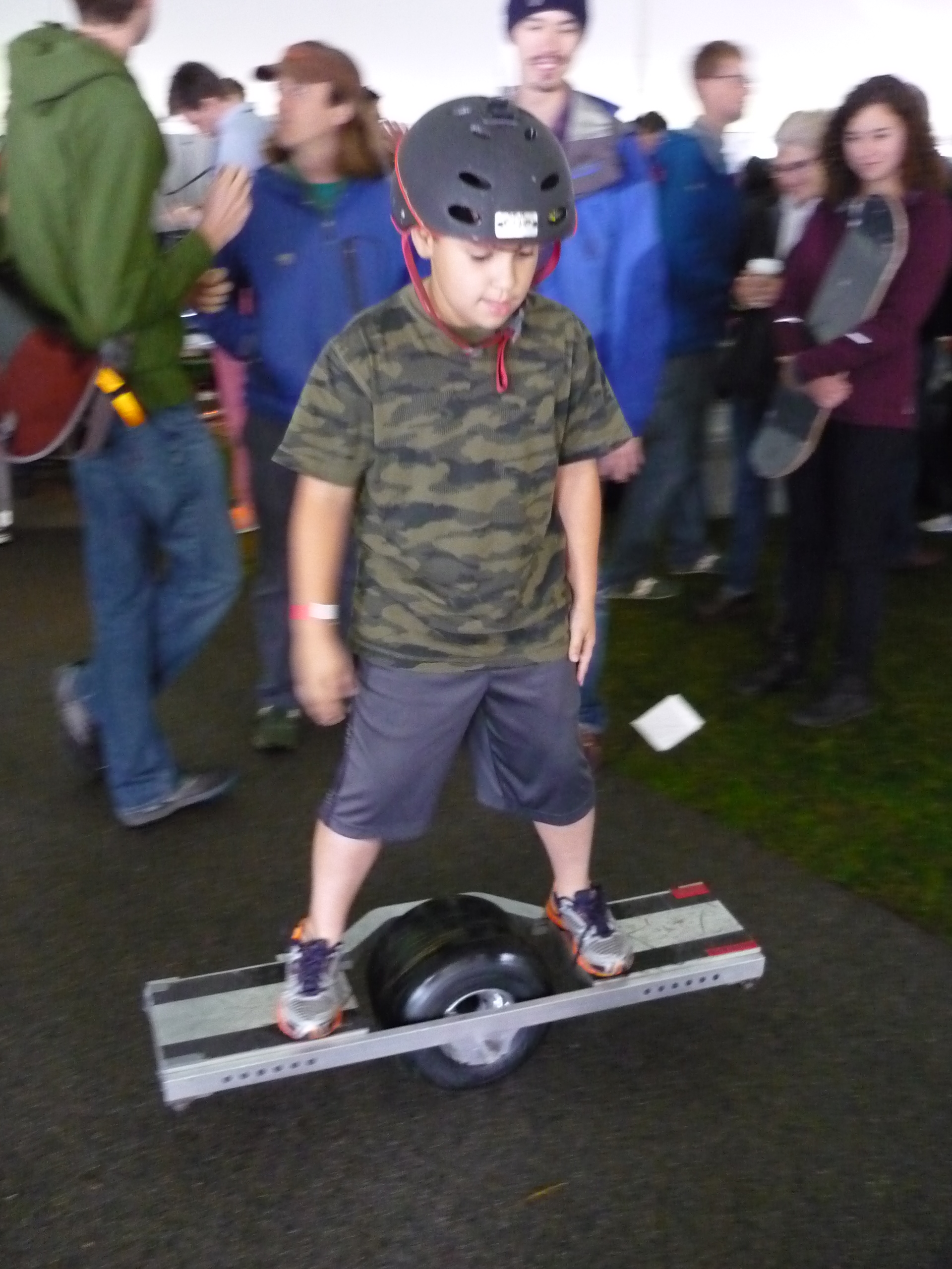 |
 |
| It was interesting to see how people attempted to ride the contraption. Folks who had skateboarded before had, suprisingly, the hardest time, as they operated with 'this is a skateboard I must make it balance' mode, and fought the control loop. A number of children FROZE in place, which, suprisningly works well. After a few seconds they would 'thaw' and then loose control. Suprisingly parent-folk assumed this contraption was 'safe' and were throwing their kids at riding it. This included, what appeared to be a ~5 year old child. They had a waiver-wristband though! | 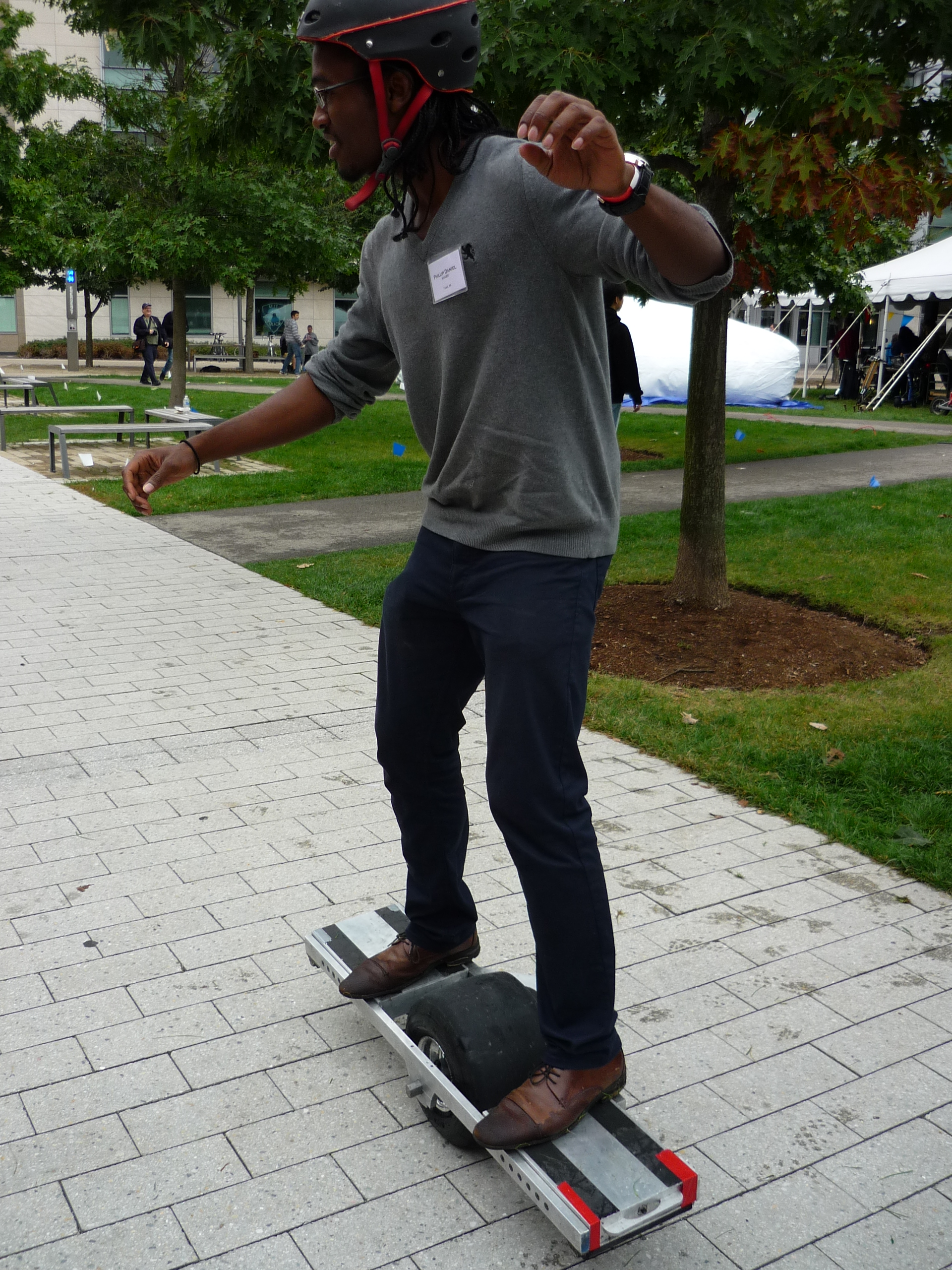 |
 |
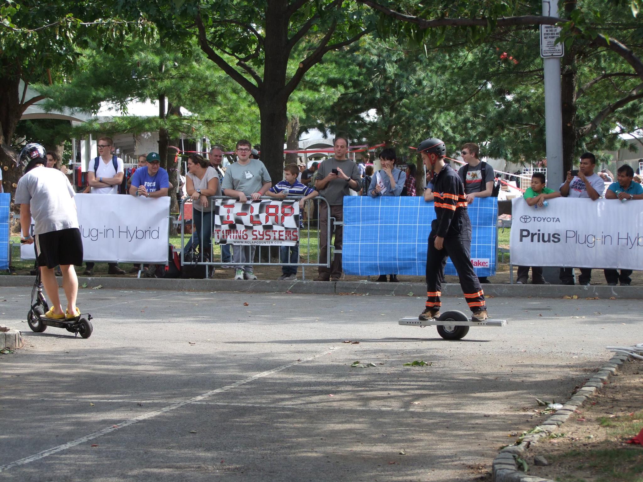
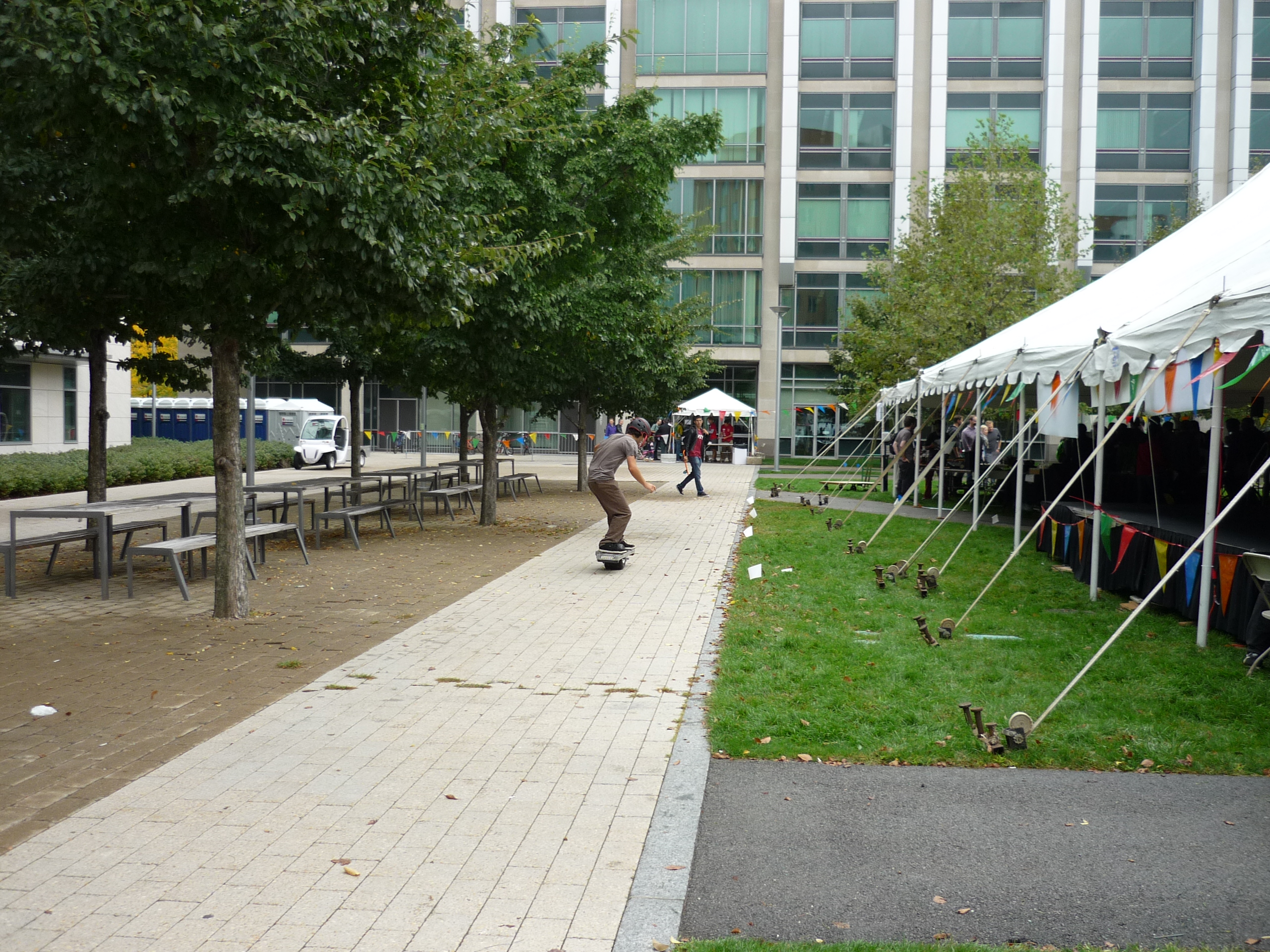
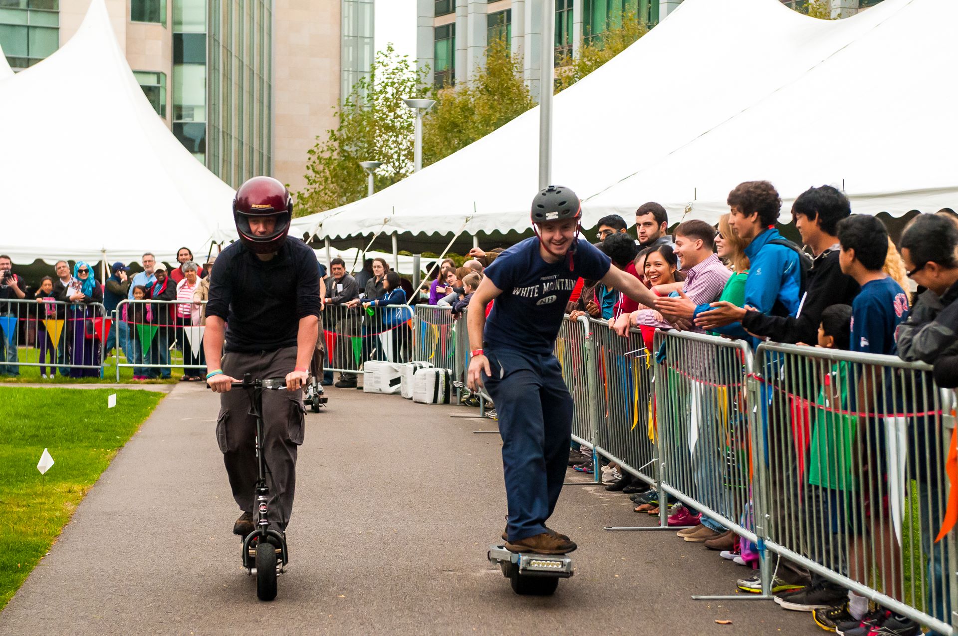
| Hovering along
in the silly vehicles race The seg-board is not an incredibly fast or efficient vehicle. I grabbed a number of highfives as I scooted around. Shown close right Ciaron showing off his scooter, and far right, the mighty Bercu on herpybike. |
 |
 |
| Post
MIT-Makerfaire Repairs The nimbus had a lot of ride-time at the MIT Makerfaire. Three full 300-watt-hour charges worth. It also incurred some hefty damage along the way. There were gnashed gears, bent motor axles and some newly leaky rims. Shown below are upgrades |
| Motor shaft
stress At the MIT makerfaire i did not have a maximum mass-limit, and unfortunatley this resulted in the motor shaft bending significantly (shown right). Time to add a rider max-mass limit :/ |
 |
 |
| Wheel leak A slow leak developed through the aluminum rim in a location i had welded over. After a number of attempts (and a number of trips to re-seat the tire) I took some advice from a comrade "dont they make friggin inner-tubes for those". Turns out they do and they are fairly cheap! [link] |
 |
 |
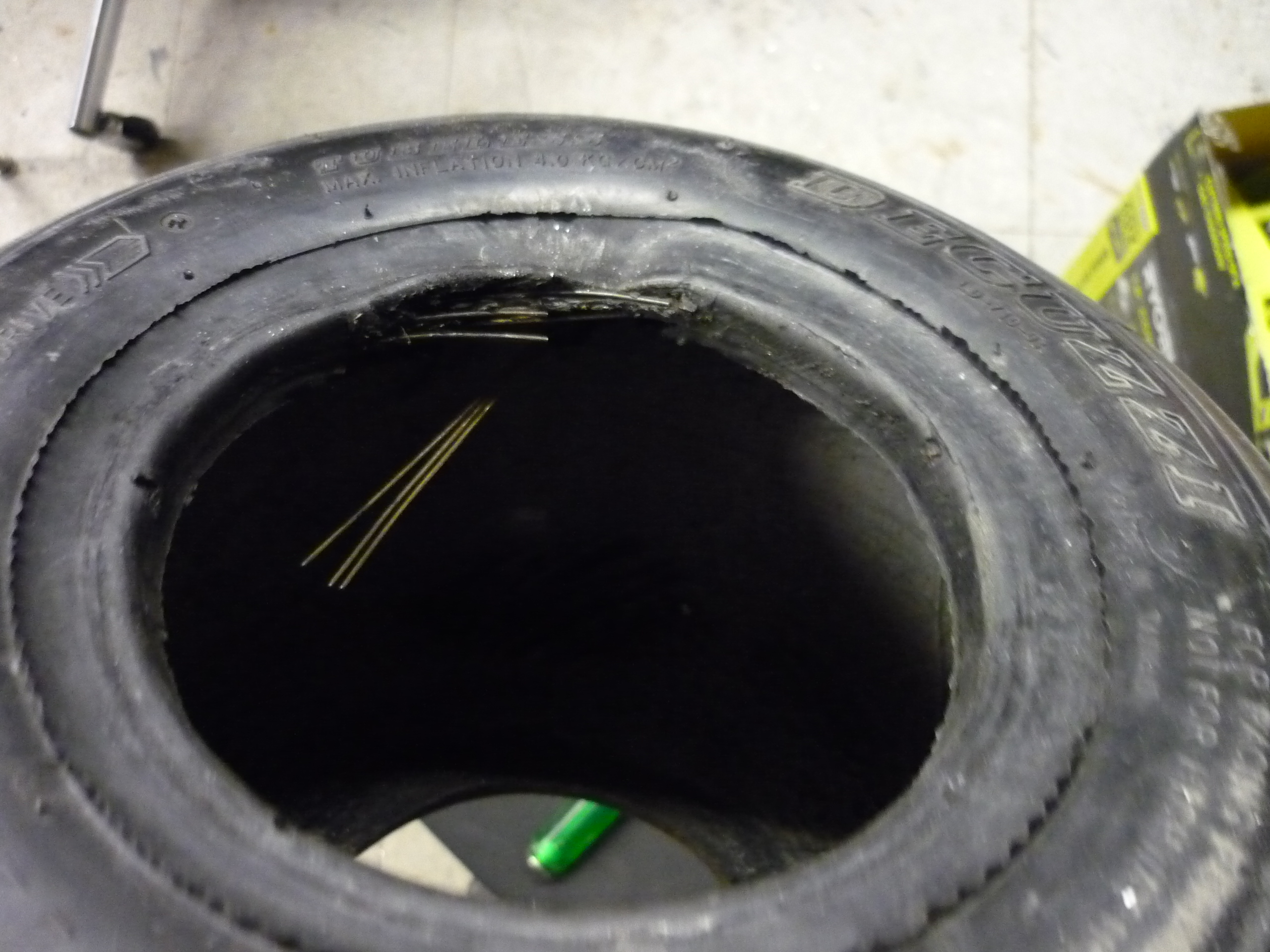
| Tire desintigration It turns out, you can only remove and re-seat a tire a heavily used tire a fixed number of times before it falls apart. |
 |
 |
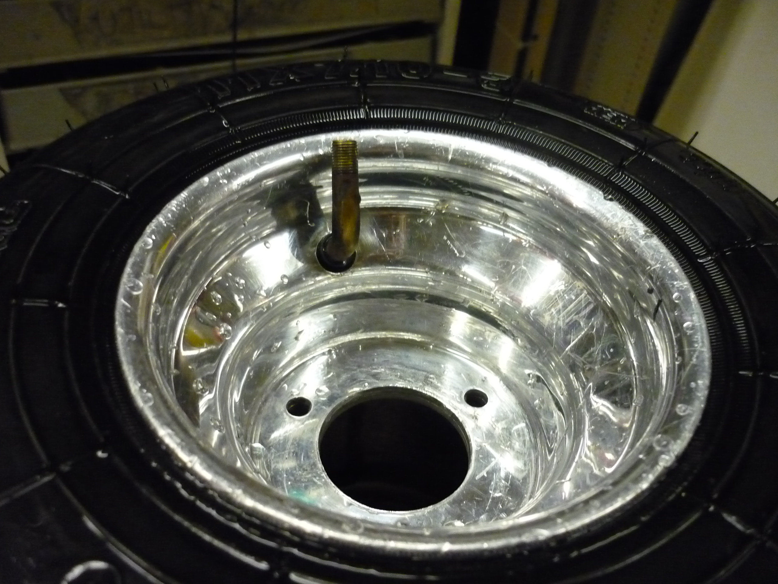
| A tube from ebay fit the bill just fine, I seated another used tire, from the kind folks at F1 Boston, removed the valvestem I had added and carefully inflated the tire, using soapy water to help get the outer rubber tire to seat well on the rim. | 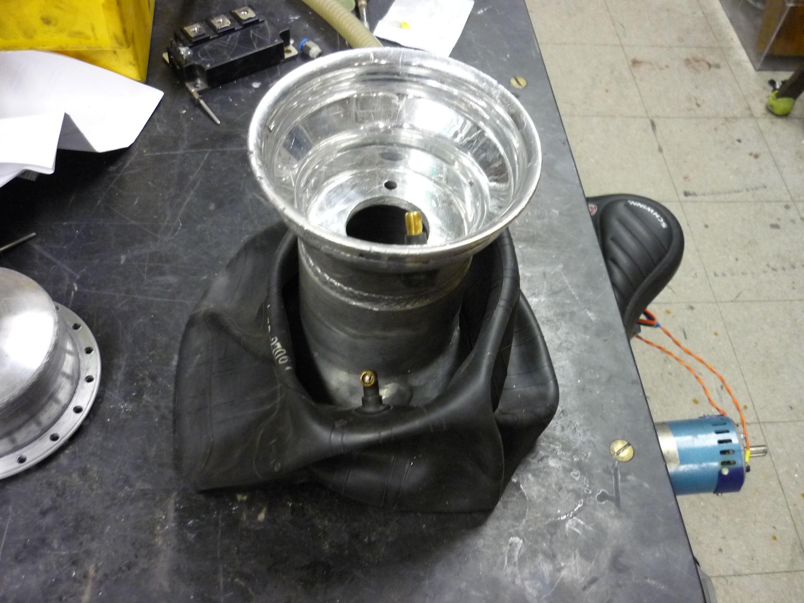 |
 |
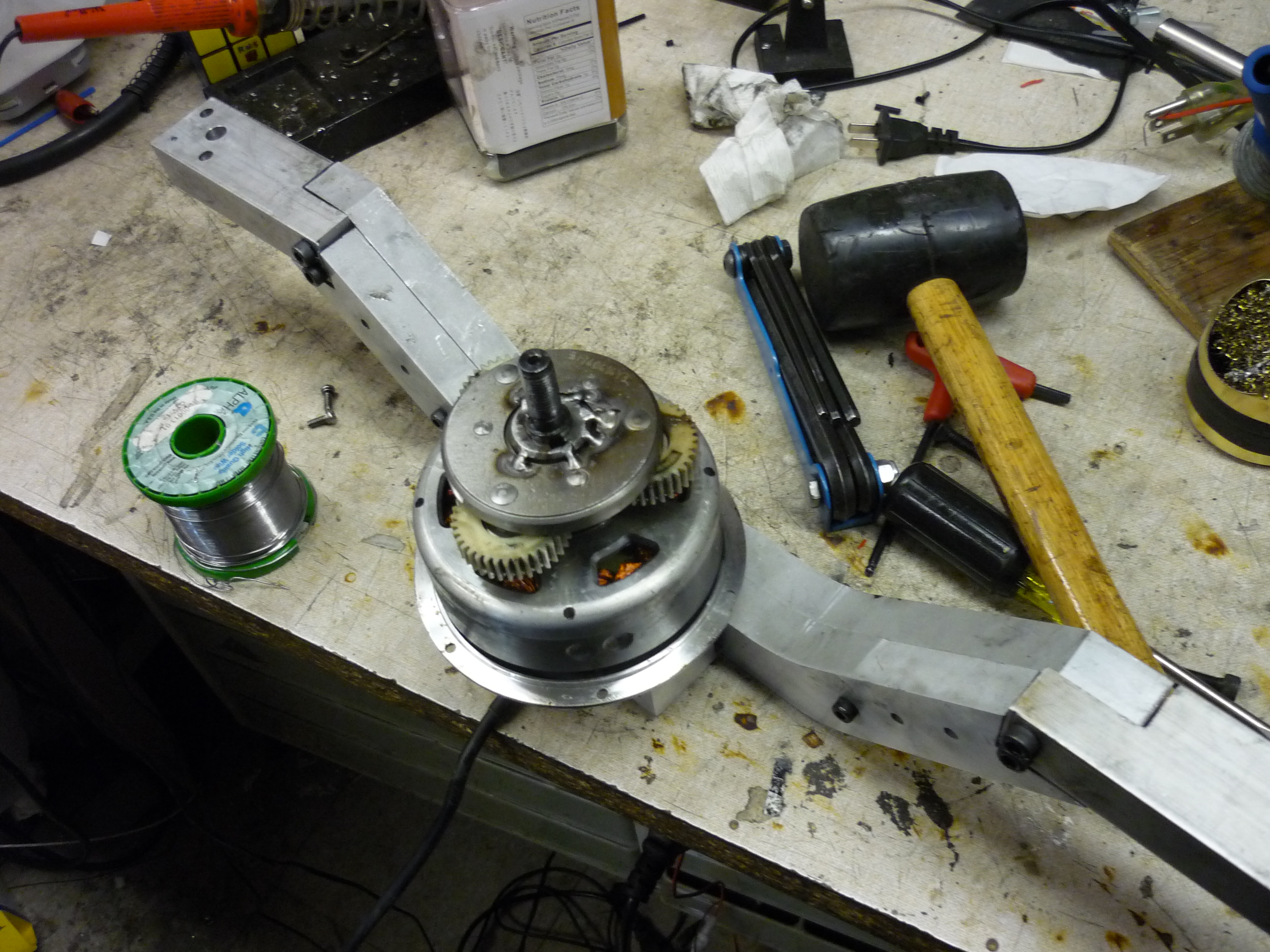
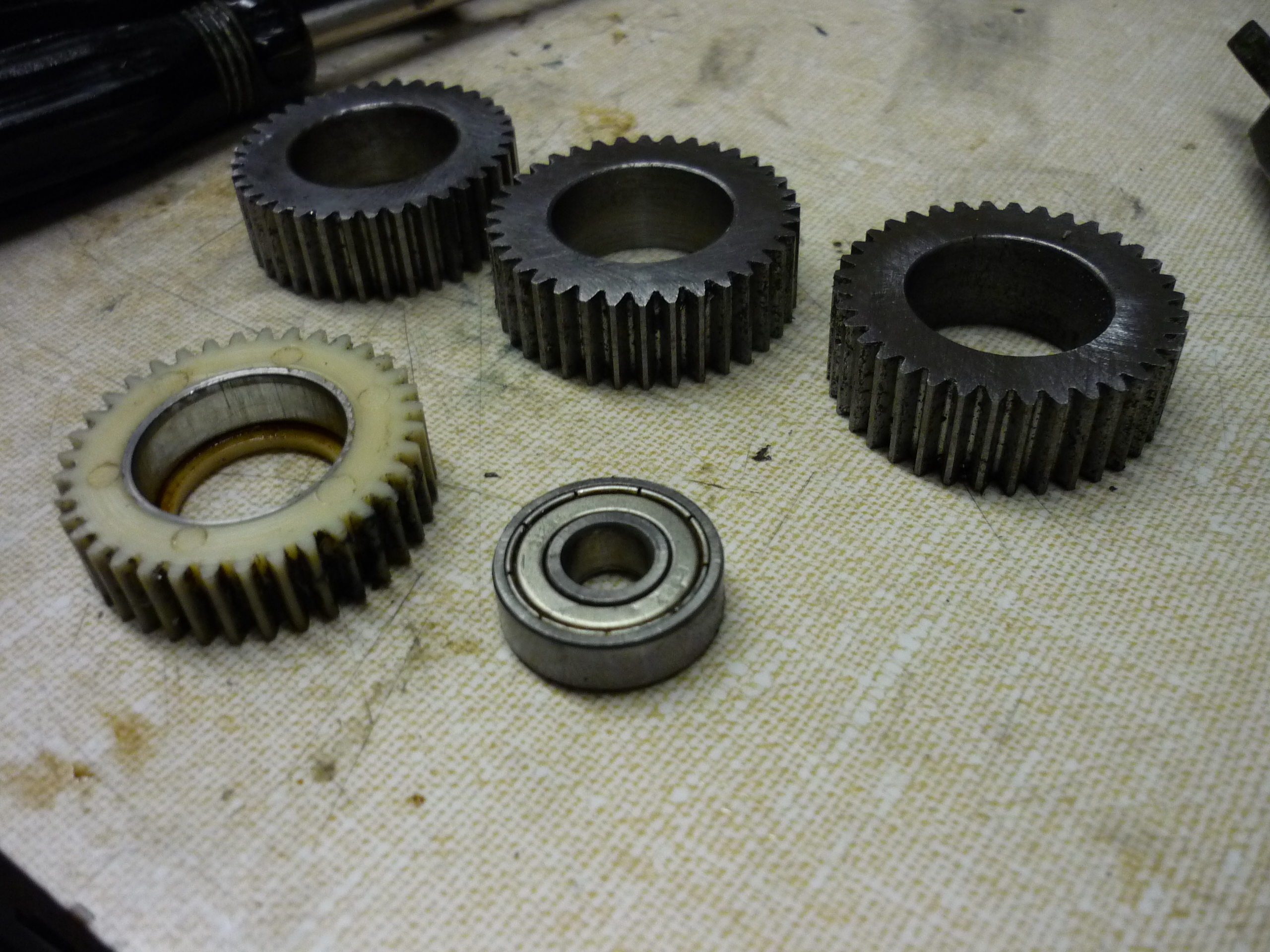
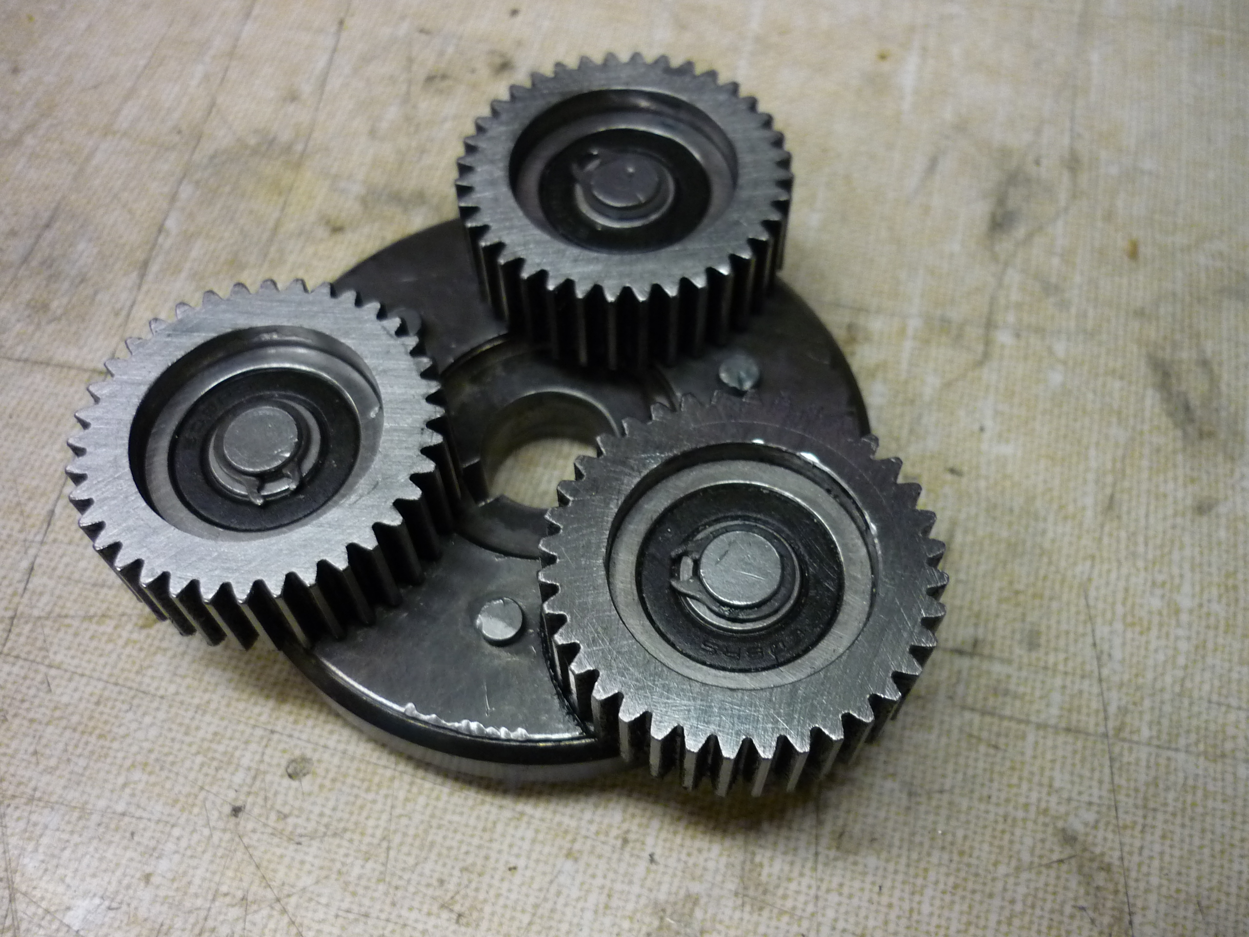
| GEARS The gears themselves got fairly gnashed-up. These are 36 tooth module-1 gears with a 20 degree pressure angle, stock, they are made of nylon. Mostly visible is the aftermath, a few missing teeth and a few smushed ones as well. |
|
 |
| Unfortunatley gear mushing this is a common failure mode observed by the folks on endless-sphere [link]. I quickly modeled a MODULE-1 36 Tooth gear for waterjeting out of 1/2" thick steel. The part came out great, but it appears the waterjet offset was a bit off (the teeth are artificially skinny). The part would work, but be rather noisy, as the added back-and-forth backlash would be fairly high. Fortunatley there are Rob Reeves in the world who know how to make legitimate gears. MORE GEARS AHOY | 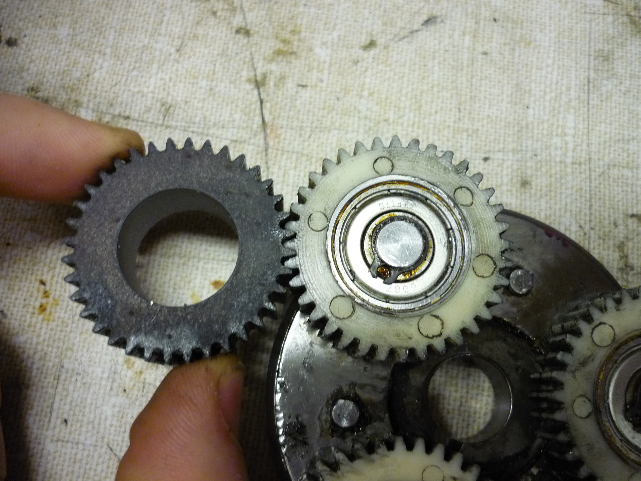 |
 |
| Out come the soviet-era gear cutters! I water-jet some round steel stock to be used as blanks for the 'reeving' process, Rob fabricated a spindle with a dye-cut thread for keeping everything in place.These stacked rounds will be lathed to the same size and used in the spur gear-making pricess. The outer diameter of the rounds, as well as the inner dimension are very specific, too large and the planetary geartrain will not fit together, too loose and the inner flanged bearings will not press-fit inside, and the gears will have a boatload of backlash. | 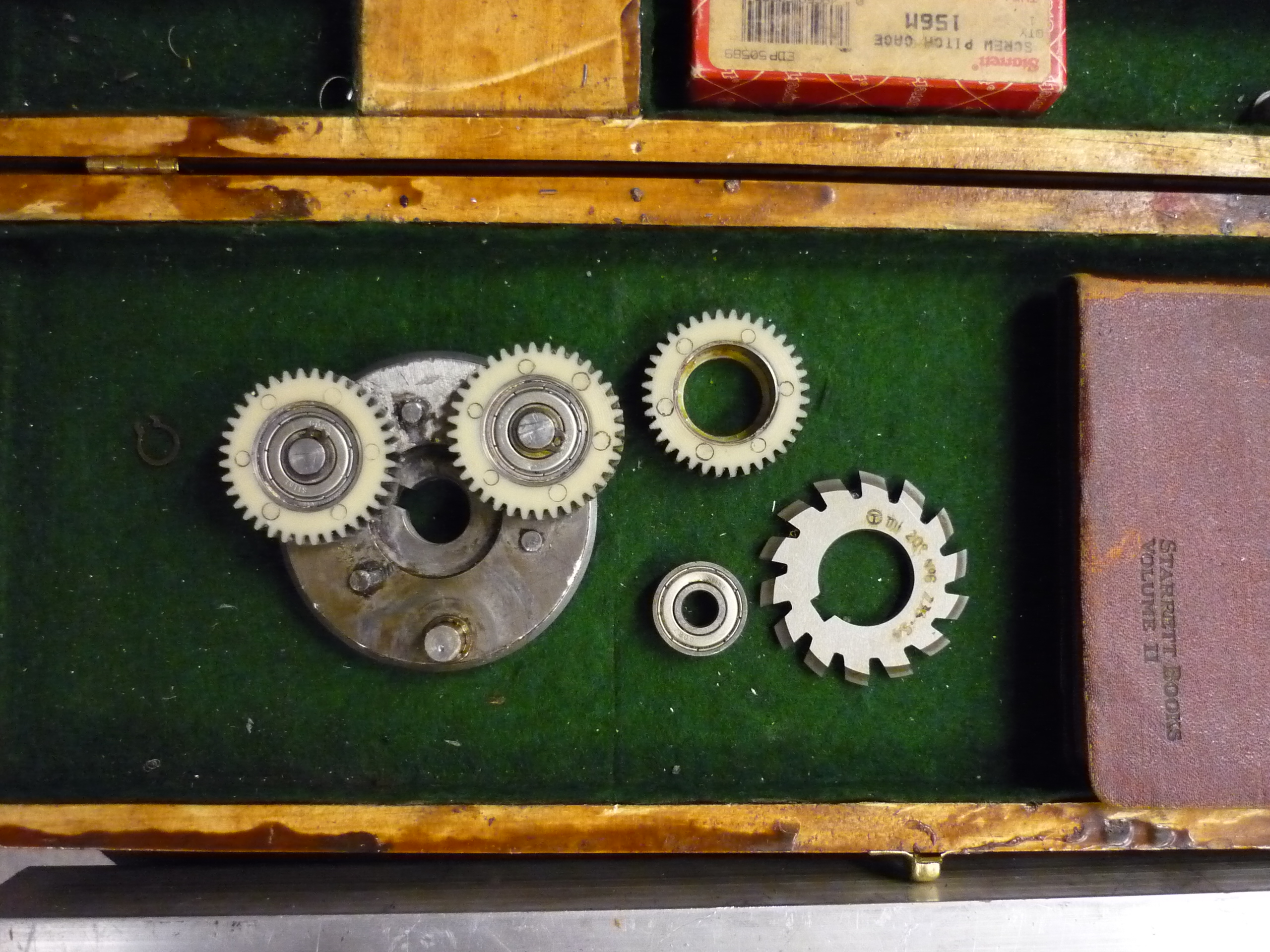 |
 |
| A large portion of the gear-cutting process is prep-work. Shown (right) is Rob cutting down the samples and building a spindle for holstering the pre-cut steel and brass rounds. The holster consists of a shaft, adapter to mount to an indexing head and dye-cut threading for tightening the steel & brass rounds in place. |  |
 |
| Setting up the gear-cutting head The gearcutter position is critical, needing to start precisely in the center of the round. The cutting depth is also fairly critical as the depth offsets the start of the involute curve, causing the mating surfaces to not mesh properly. |
 |
 |
| Switching a 36V
hub-motor from nylon gears to steel Previously (above) I had used the 48V variant of the 8-fun motor, namely because the first servo controller i had access to was only able to run at 6A but allowed for high voltage operation. With the newer A-M-C drive, i could now operate at a more tolerable battery voltage |
 |
 |
| Steel gear
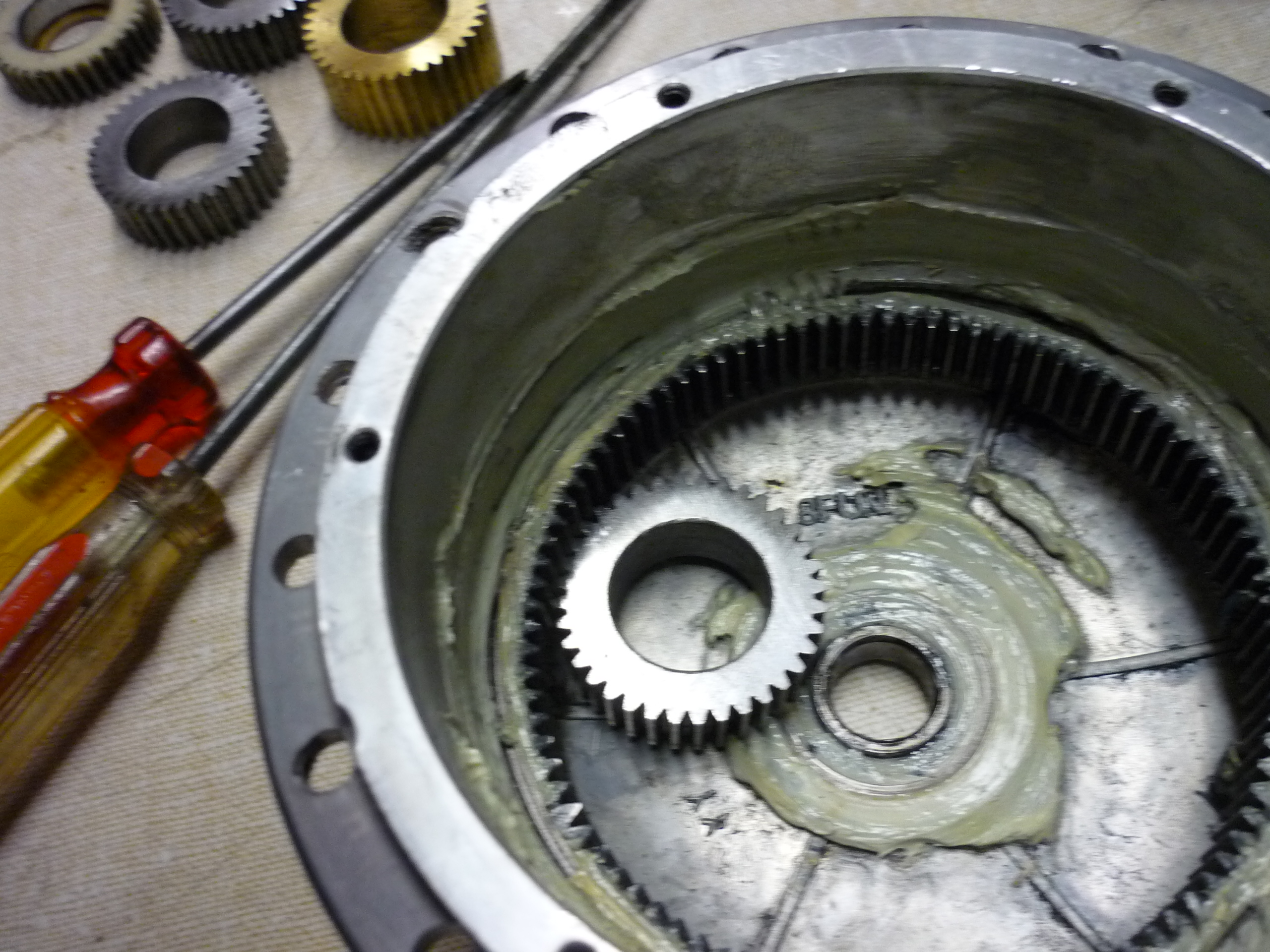
lineup Shown (right) is one of the steel gears Rob synthesized. Its a frigging fantastic fit. Further right is a re-welded, wirewheeled planetary holster with the three steel gears in place as a mockup. IT LOOKS FANTASTIC. |
 |
 |
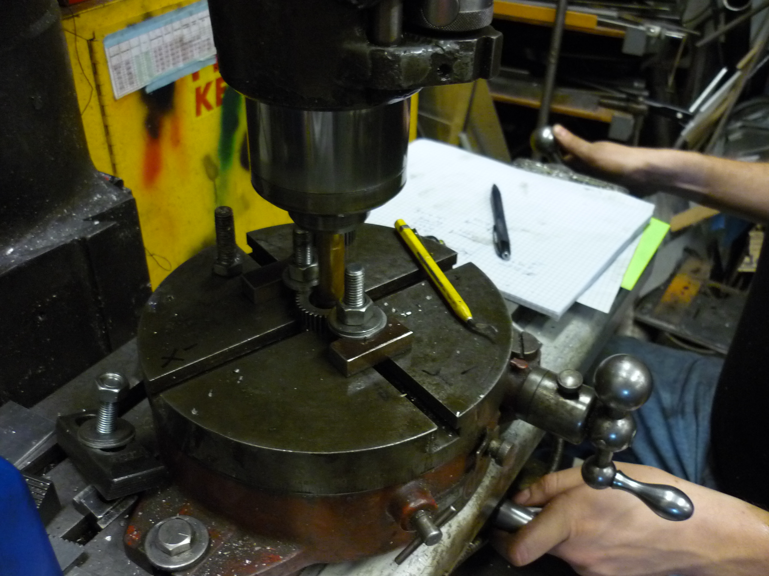
| Setting up for cutting out the space for a flange. The gear is held in a rotary table by clamping onto the flat face of the hobbed gear and a precise measuring head is used to locate the center of the gear. | 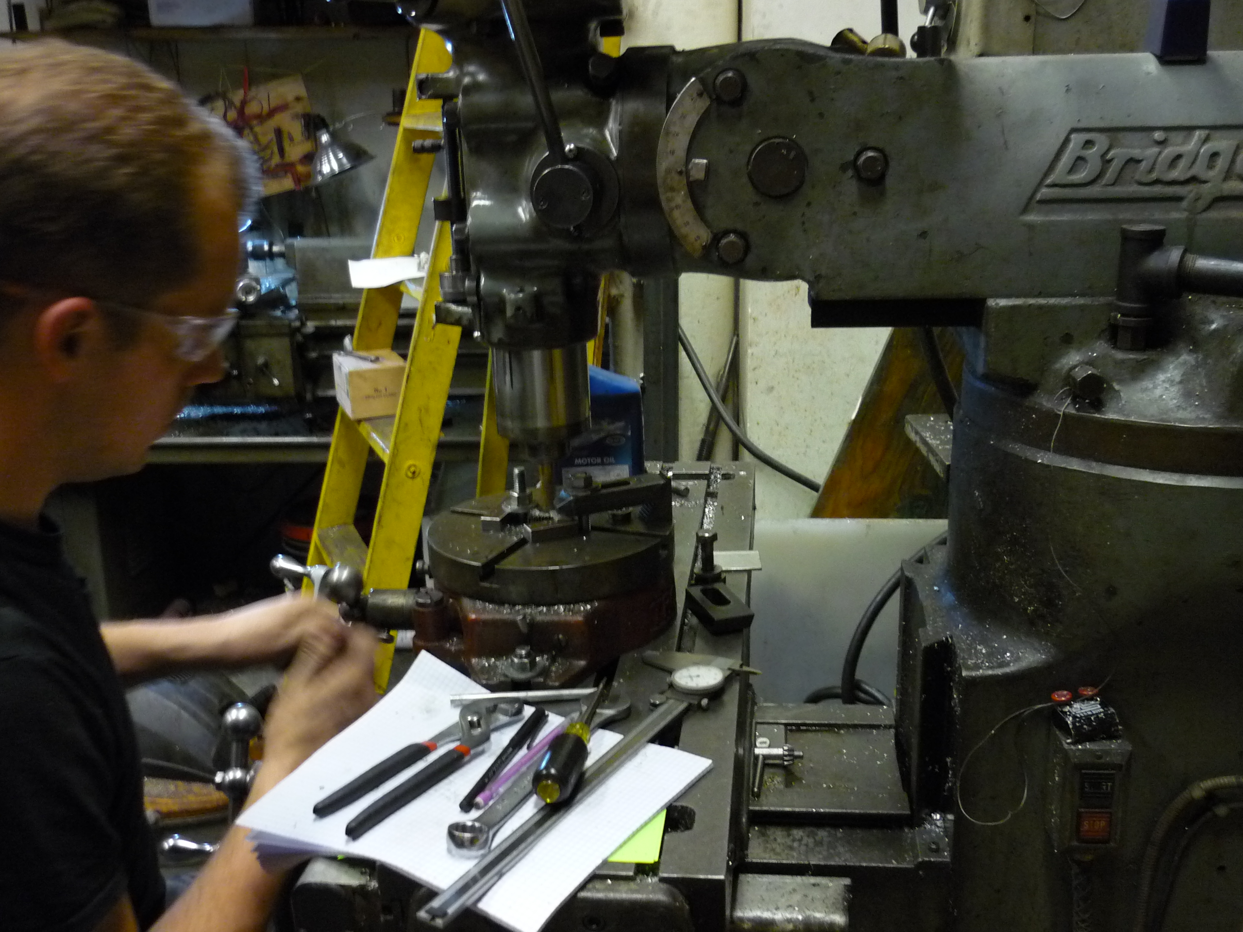 |
 |
| Milling the
flange holster The bearings chosen for these gears are [link] 22mm x 8mm x 7mm flanged. The flange constrains the gear from coming off inside the planetary and a press-fit prevents it from colliding with the base plate of the planetary holster. Shown here Rob uses a rotary table and a small offset to mill out a press-fit socket for the bearing to sit in. |
 |
 |
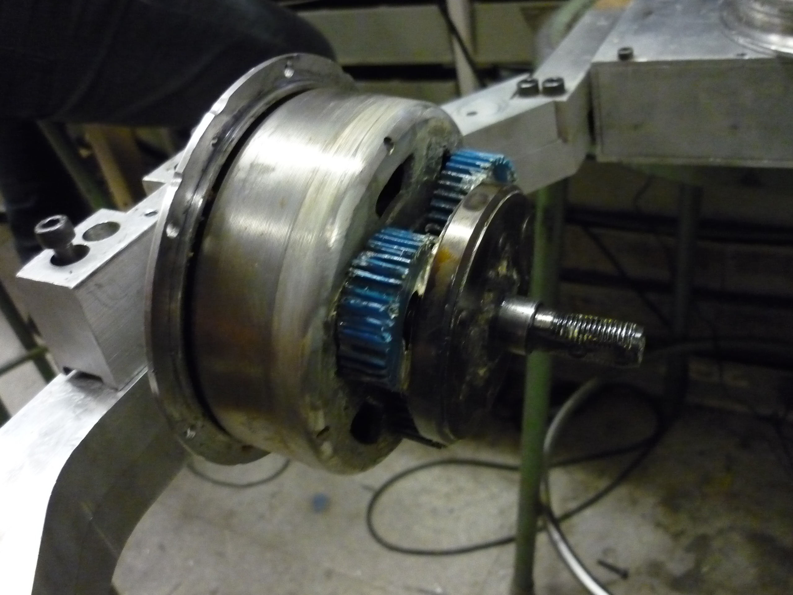
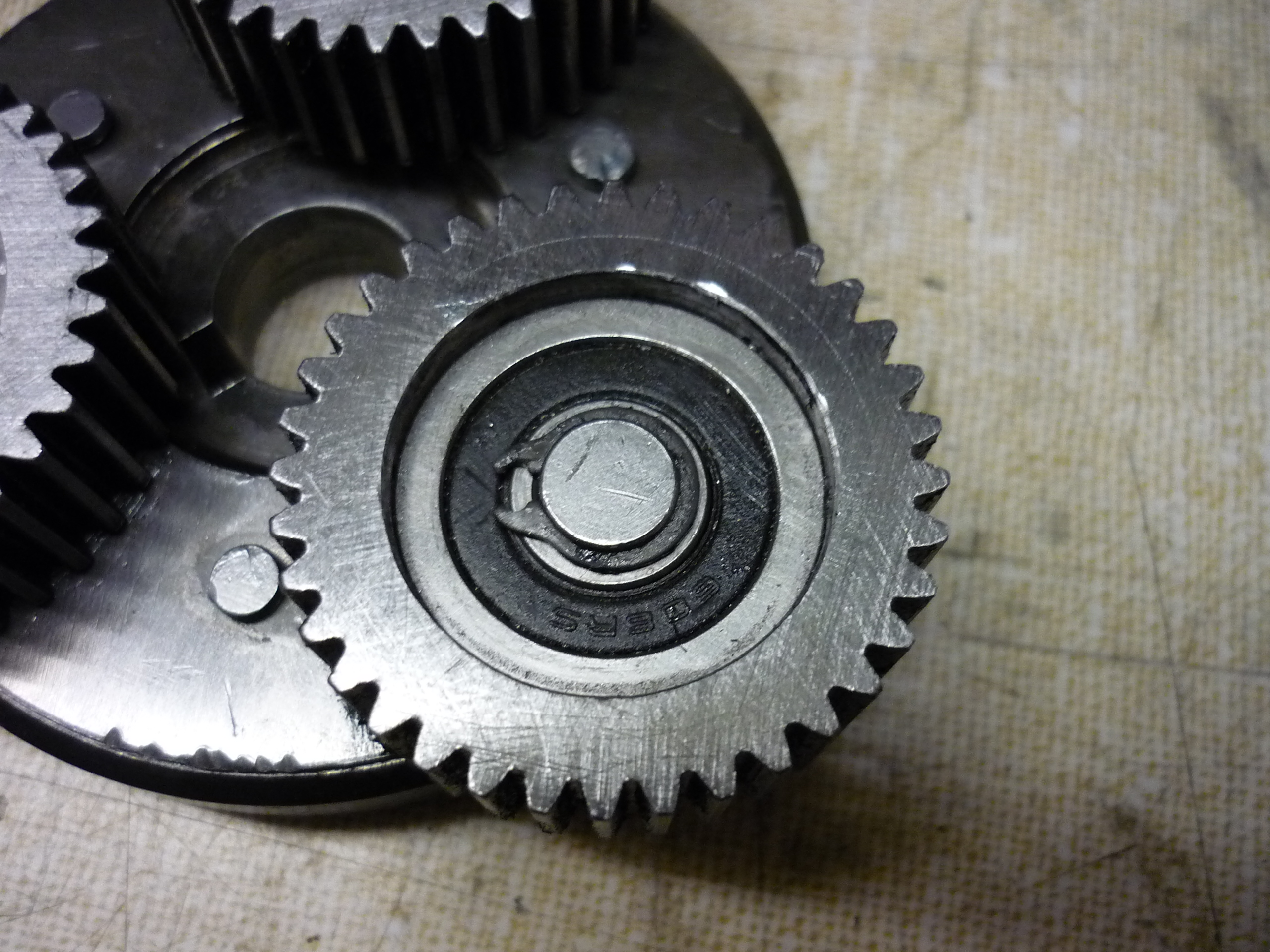
| The new upgraded planetary gear train planet
gears. Note the bearings are 22x7x8mm flanged-style. The 'flange holster' detailed above constrains the bearing from coming out vertically. ITS BEAUTIFUL. |
 |
 |
| Adding bluetooth for PID tuning |
| Using details from [link] bluetooth reprogramming was added to the internal microcontroller hardware. Suprisingly the bluetooth was able to connect reliably through the fan-grating holes for reprogramming. Quite a bit of time was spent tuning the PD control loop to have a useful feedback setup. | |
 |
| To make life simpler, components for the bluetooth reprogramming module were tacked directly on the module and encased in electrically isolating heatshrink. With this working, updating constants only required parking the vehicle, firing up the arduino development environment and updating control constants. |  |
|
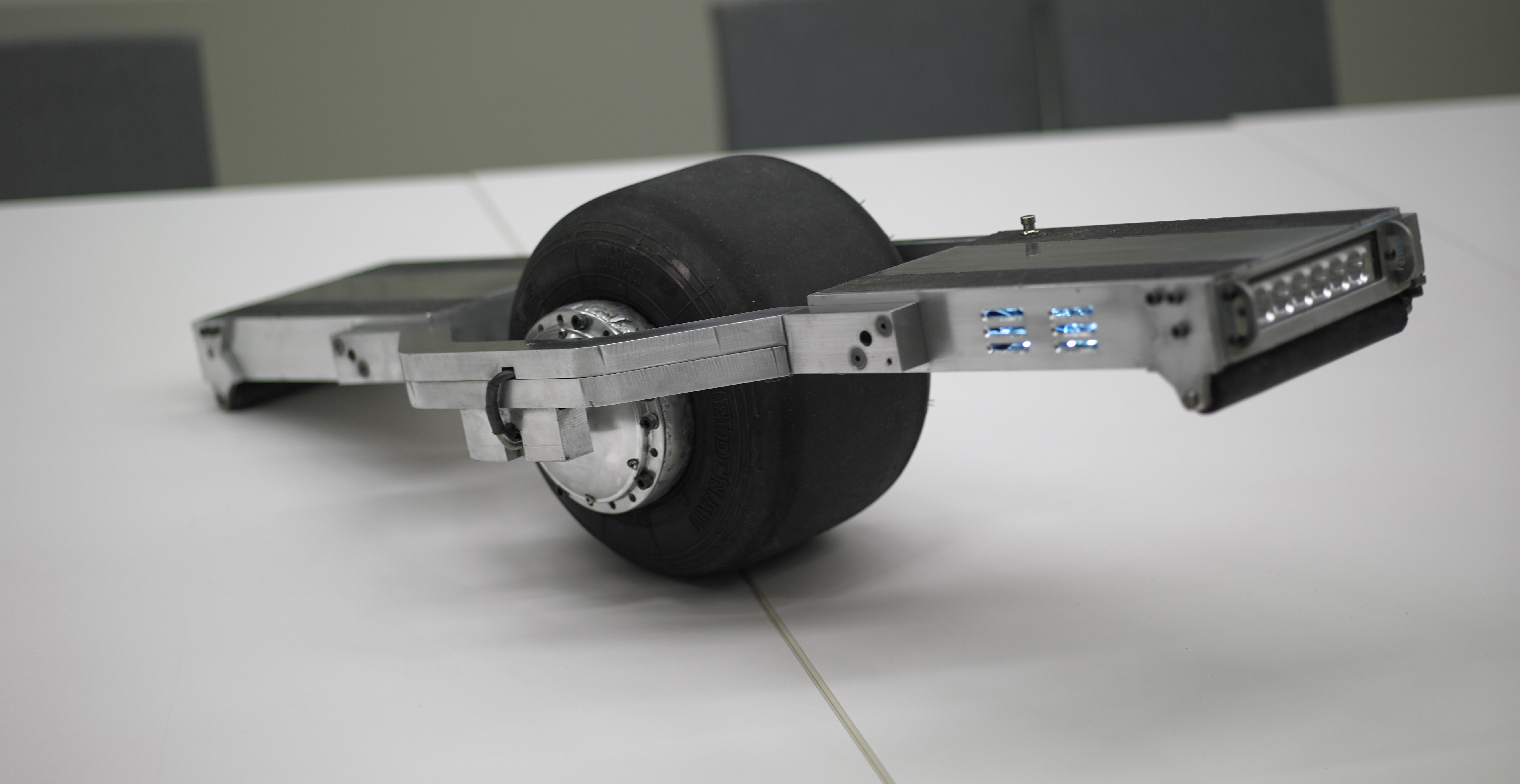
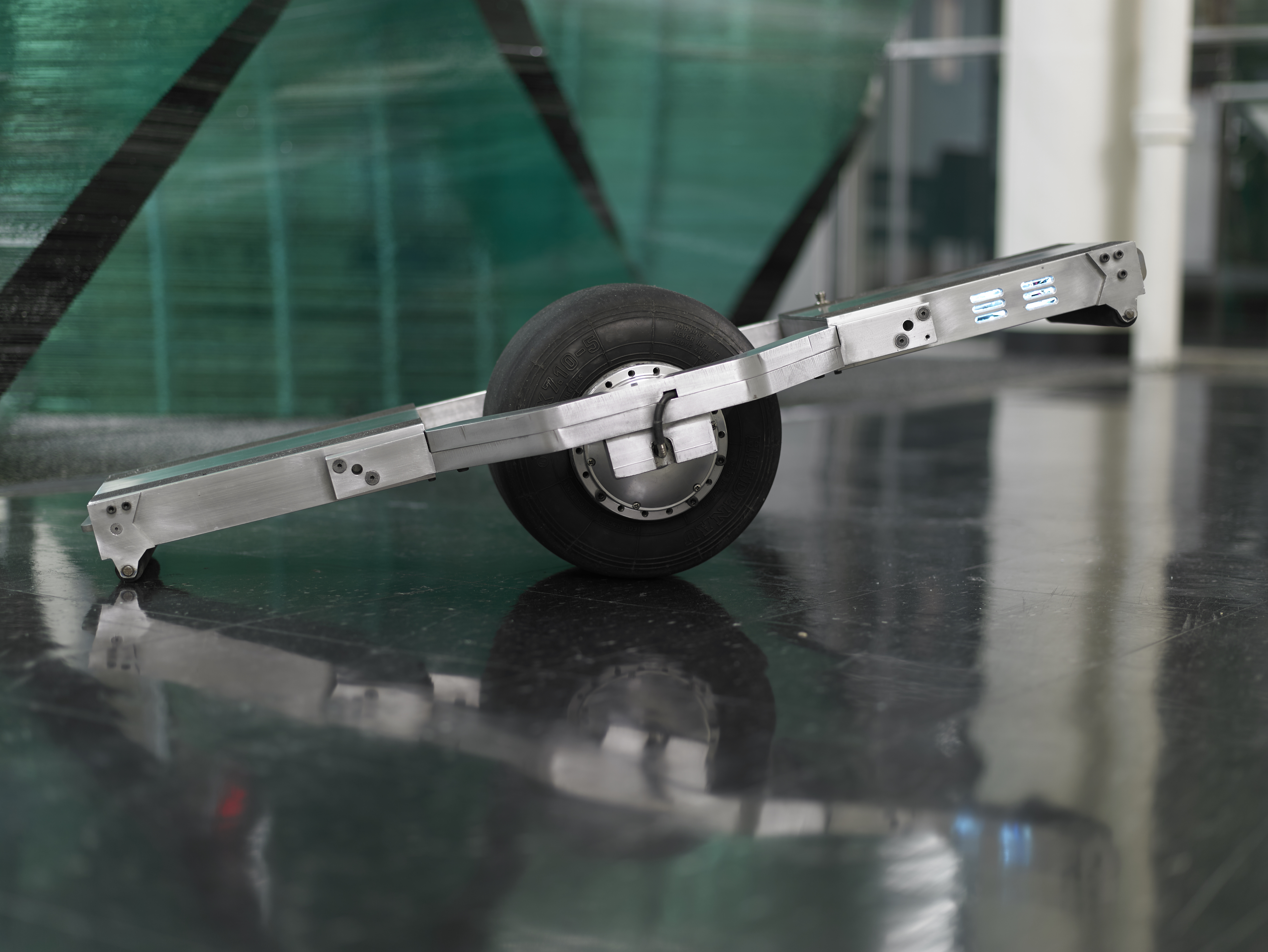
| Swanky Photos |
| The ever excellent Bayley Wang and way-more-artistically-inclined Sonya gave a hand at taking some glamour shots. These were taken with a phase-one monster-beast. |
 |
 |
 |
 |
 |
|
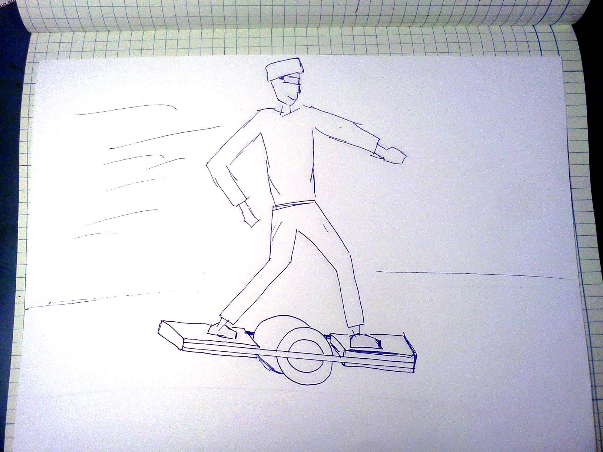
| The 'Flying Nimbus' background |
| The flying
nimbus is a (potentially)
fictional contraption which floats about in the Dragon
Ball Z universe. It flies around as a vehicle and can
be only used for good. On a number of situations it
swoops in to save the day, or provide a rescue
mechanism for a hero / heroine. I could totally use a flying nimbus |
 |
 |
| Further background... A comrade had mentioned that the whole 'walking on a flying cloud' thing wasnt a new premise, it was actually based on something called 'Journey to the West' which mentions topics like walking on clouds and fantastic adventures. More information about 'Journey to the west / Monkey' available here: [link] |
 |
 |
Special Thanks:
AMC
AMC saved the day on this build, donating an AZB60A8 three-phase servo drive. It preformed phenomenially, even with some interesting riders, smashing between forward and reverse and bouncing all around. Not only did it survive the electrical loading, the shock-and-vibe from this application is enormous! Give one of their drives a whirl, they are fantastic
Thanks again A-M-C!
MIT Hobby Shop
The hobby shop is full of friendly helpful staff and a beautiful waterjet that I ended up visiting on a weekly basis. Thanks again hobbyshoppians for putting up with the variety of my queries and providing useful feedback!
MIt's D-Lab
DLAB was kind enough to let me use their welding shop after hours to tack miscelaneous parts of this project together/ back together. Thanks again Jack!
Miters: Where this contraption was born! A majority of the machining and debugging occured here over a few weekends and late evenings. Thanks Mars for the mechanical feedback, Bercu for the torque carrier ideas and Mike for initially test-piloting the beast.
Formula 1 Boston:
Formula 1 Boston was awesome enough to donate two used tires for this project, its a fantastic place and well worth a visit!
(There's
other
photos in the photo gallery)
Concluding Remarks:This project was iterative, it evolved from a basic layout and grew to increase in power (6A-->20A), change structrual design and hardware layout. The most interesting aspect is getting feedback from letting other people ride. The front/rear rollers were born from necessity, new and seasoned riders would crash into walls and chew up the frame. The control loop evolved to compensate for different conditions and filtering was adapted in to fix sporadic headlight flickering. Mechanically the hub-motor assembly grew from a single-bolt mount to a monsterous shaft adapter to transfer the vehicle torque out to the wheel and frame. Iterative design, and designing for future upgrades makes a huge difference. Feedback from others on 'it should do x' or 'it does this weird' was huge. If you want to know the limits of your machine, give it to others, or more specifically children to use / destroy. Rebuild to compensate for conditions you did not imagine. Designer's mercy, or, the unwillingness to fully stress test a device can be compensated by sharing. Some people are physically larger, how much can the vehicle hold? Some are significantly taller, and the CG offset can change the operating characteristics. Can it work with stilleto toed shoes? Many thanks to miters, Charles Guan, Shane Colton, and the mighty Bercu for feedback, and feedforward.
Edit:
A number of people mentioned wanting to purchase this or something similar, check out ONEWHEEL, its fantastic and commercially available.
If you have questions or comments, ask below or send over an email.
| Comments: |
|
HTML Comment Box
is loading comments...
|
(be
careful, im not responsible for the many, many skinnned knees
and elbows incurred from PID tuning)
Dane.Kouttron
Rensselaer Polytechnic
Institute
Electrical & Electrical
Power
631.978.1650
