Dane.Kouttron
Power Inverter Mod (instructable link)
Gettin more juice (via voiding the warranty)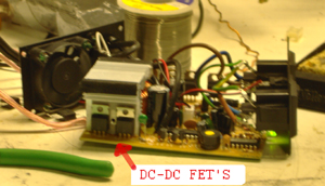
A 10 minute modification can yield a big increase in your cheap power inverter's performance
Why?
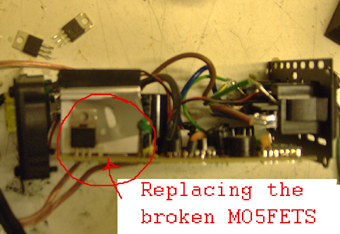
After blowing the main mosfets on a cheap power inverter (~200W) I
decided to replace the fets with slightly higher current rating
components (IRFP4232).
The power inverter consists of a high frequency DC-DC converter (boost
configuration) and a h-bridge circuit to convert the ~140V dc to 120VAC
rms. Replacing the toasted dc-dc fets does yield a higher power
output, however its important to recall that the inverter's high
power wiring want designed to pump twice the current, so as always
keep a watchful eye during operation.
-Broken/ flimsy power inverter
-Information from original inverter's mosfets (part number)
-
Simple Diagram
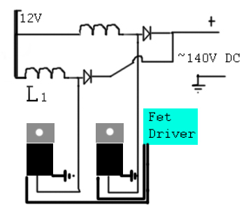 The inverter works on two bacis functional components, a power DC-DC
converter and a H-Bridge circuit. The dc-dc converter can be
represented by the diagram on the left. Obviously, this is a
simplified diagram, however the two fet's become the immediate
bottleneck for the inverter's peak output. Again, none of the
other components, like the inductor's or diodes, were specifically
designed for larger currents, but thankfully the company that built the
device embraced the idea of high durating values.
Dane.Kouttron
Rensselaer Polytechnic Institute
Electrical & Electrical Power
631.978.1650
