| Mechanical Bits and
assemblies |
|
|
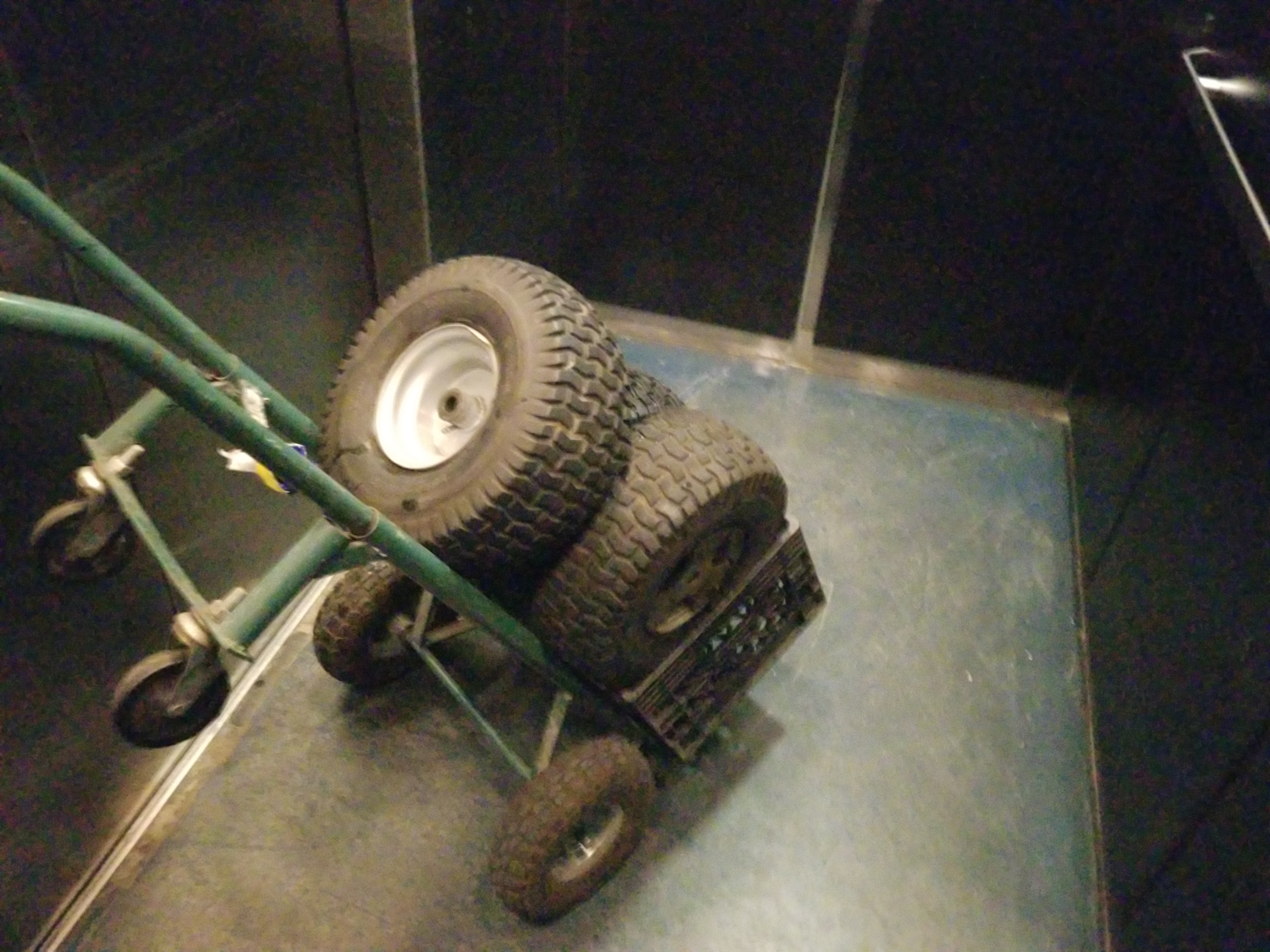
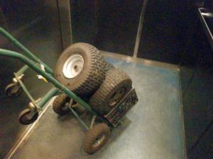
| This
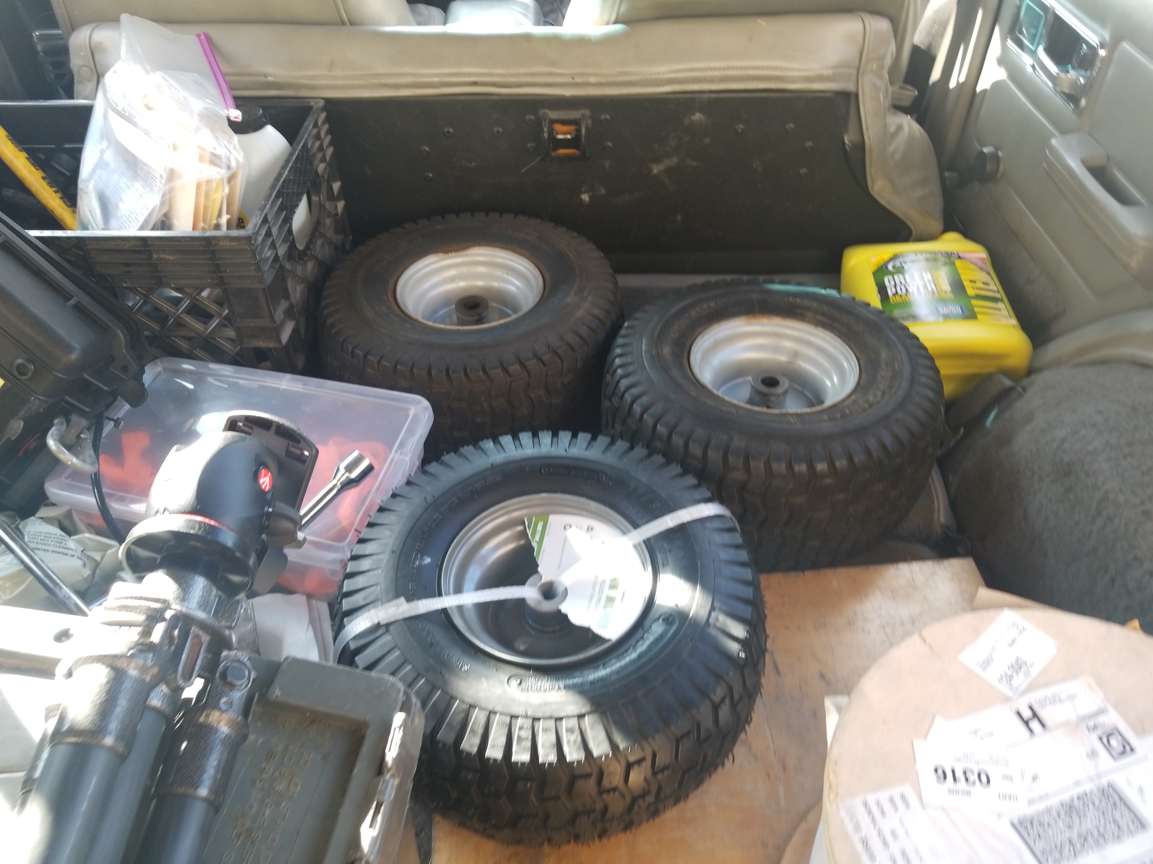
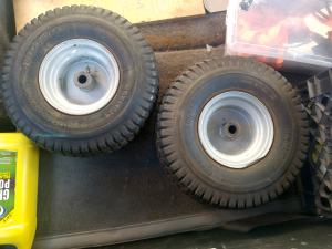
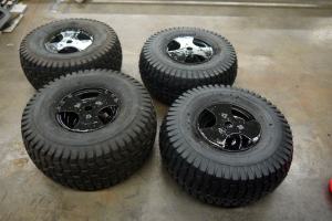
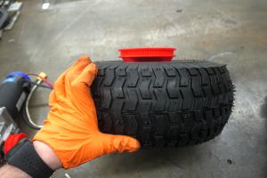
really started with some free wheels. Sibling Chris had these left over
from some tractor contraption. They are quite huge but also the right
price, free. These tires are tubed and have a bushing to mate
to a
3/4 axle. Initially I was heasitant to continue using bushings, but
these did have built in grease fittings where the grease would insert
from a cavity inside the two bushings. Theoretically as long as these
are greased before tests it should be fine as the actual velocity is
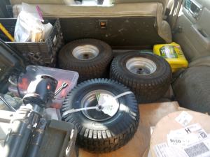
quite slow. Two more tires + rims of the same size listed used were
~50$, so I grabbed them for a 4 wheeled tank-steer rover. |
 |
 |
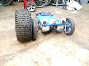
Why
bigger tires?
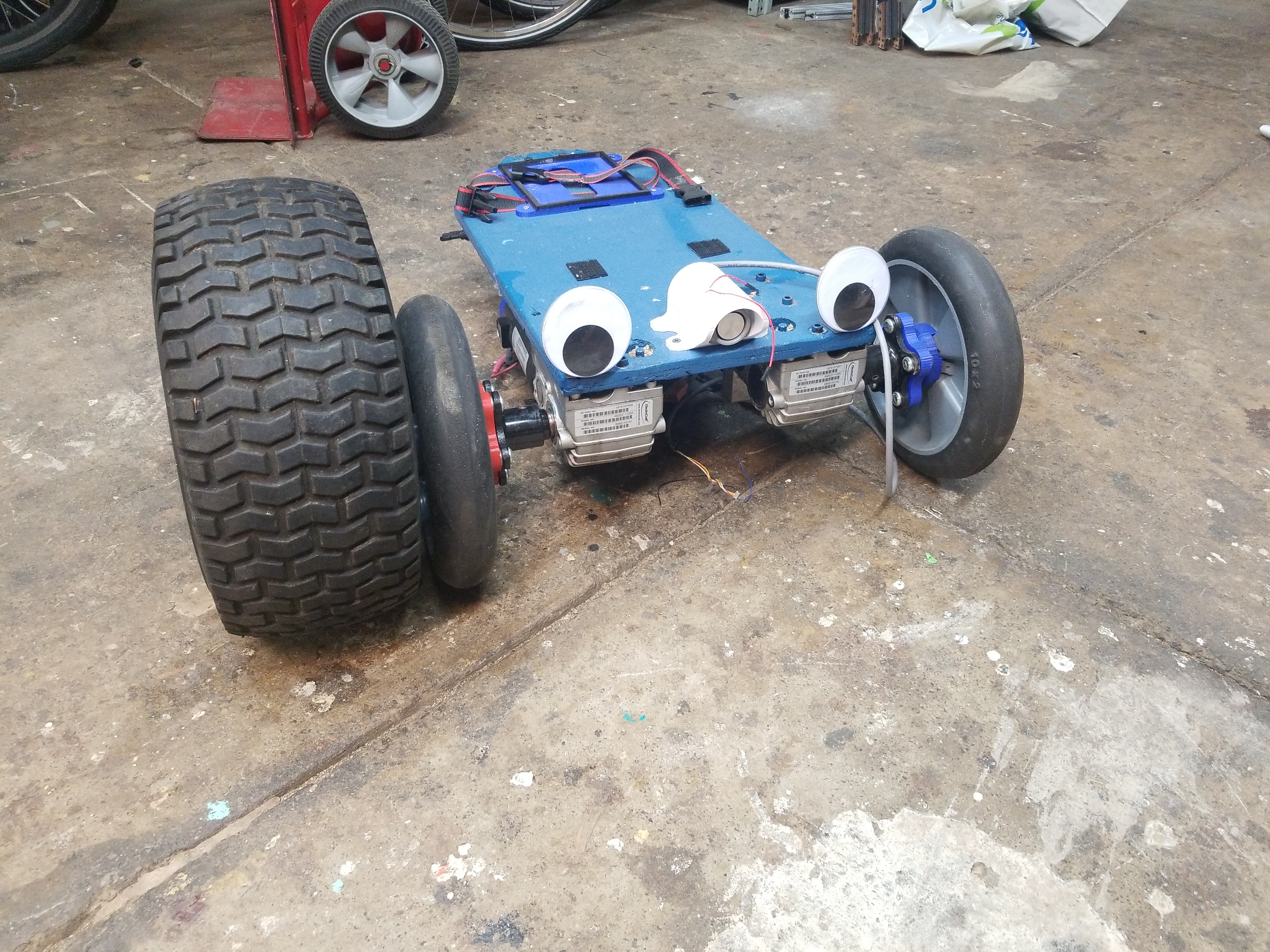
I
had a few comical issues with the solid tire+printed wheel mount last
year. The lack of clearance resulted in tesbot v1 really only working
on dry pavement, and finally when it ran into a curb due to a sensor
error, it was extremely good at shearing the wheel mounts off. For
whatever reason, last year I didnt try and make a shaft adapter, but
opted to use the 5-point bolt mount and translate that over to a bolt
to act as a secondary drive shaft. Either way its fairly visible how
large these tires are in comparison. Finally because I was going to opt
for more clearance the same wheelchair motors will be mounted well into
the chassis. |
 |
 |
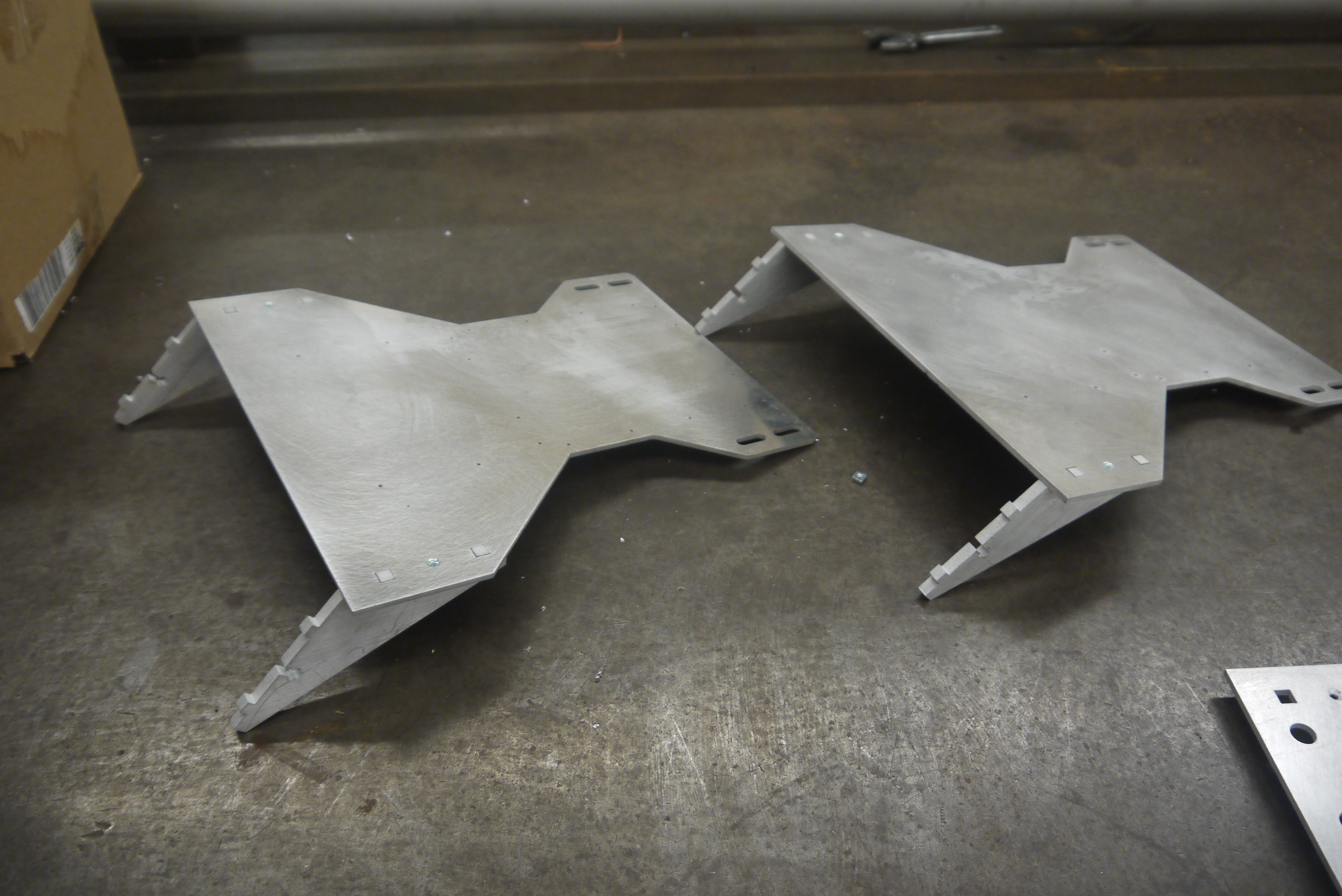
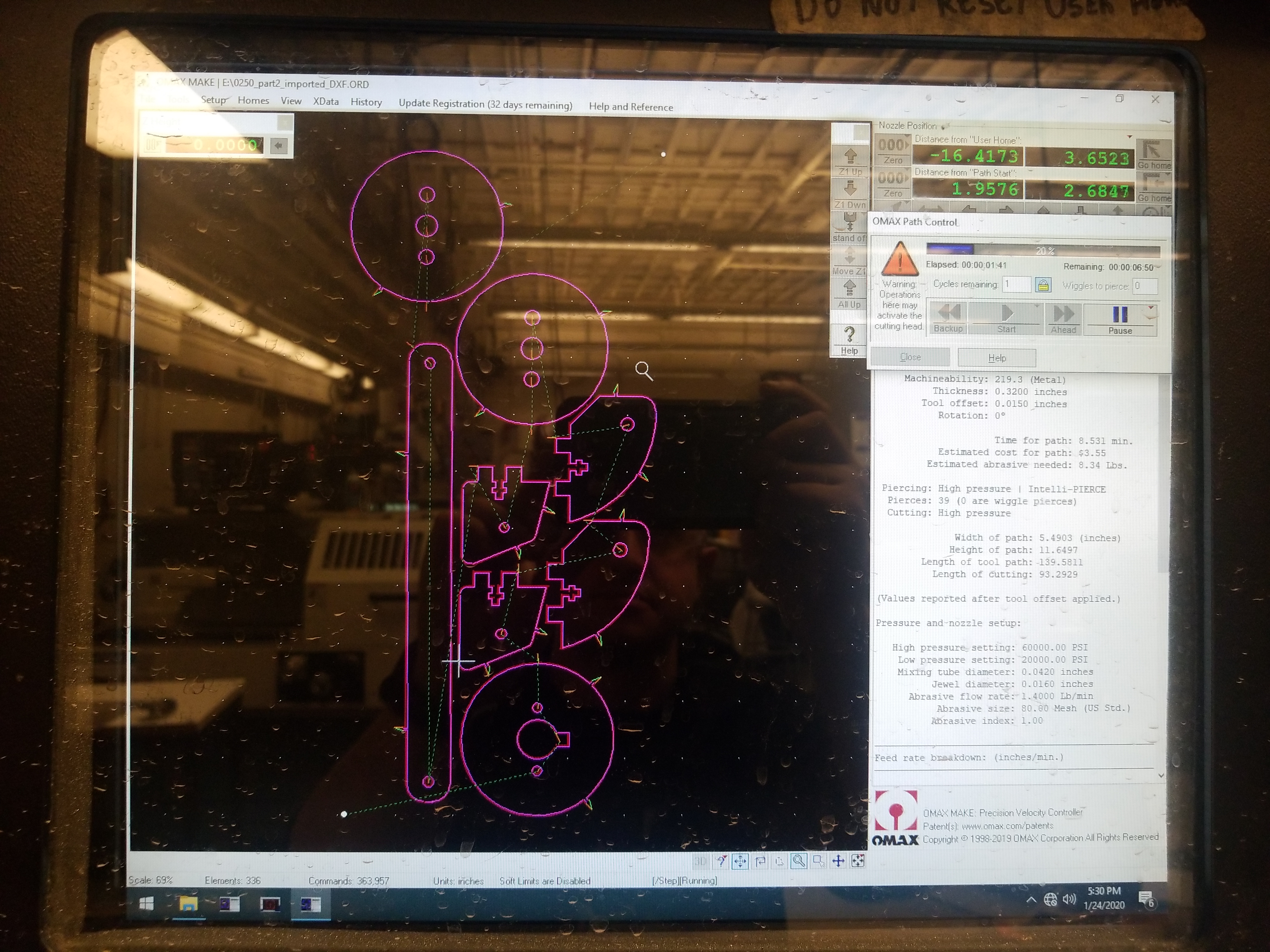
| The
whole chassis was quickly sketched up in soldworks, and to make things
'fast' to assemble, i opted for a plate-waterjet topology. This would
use some scrap aluminum and steel plates and simple t-nut style
fastening, along with some eaisly available mc-master-ables. |
 |
 |
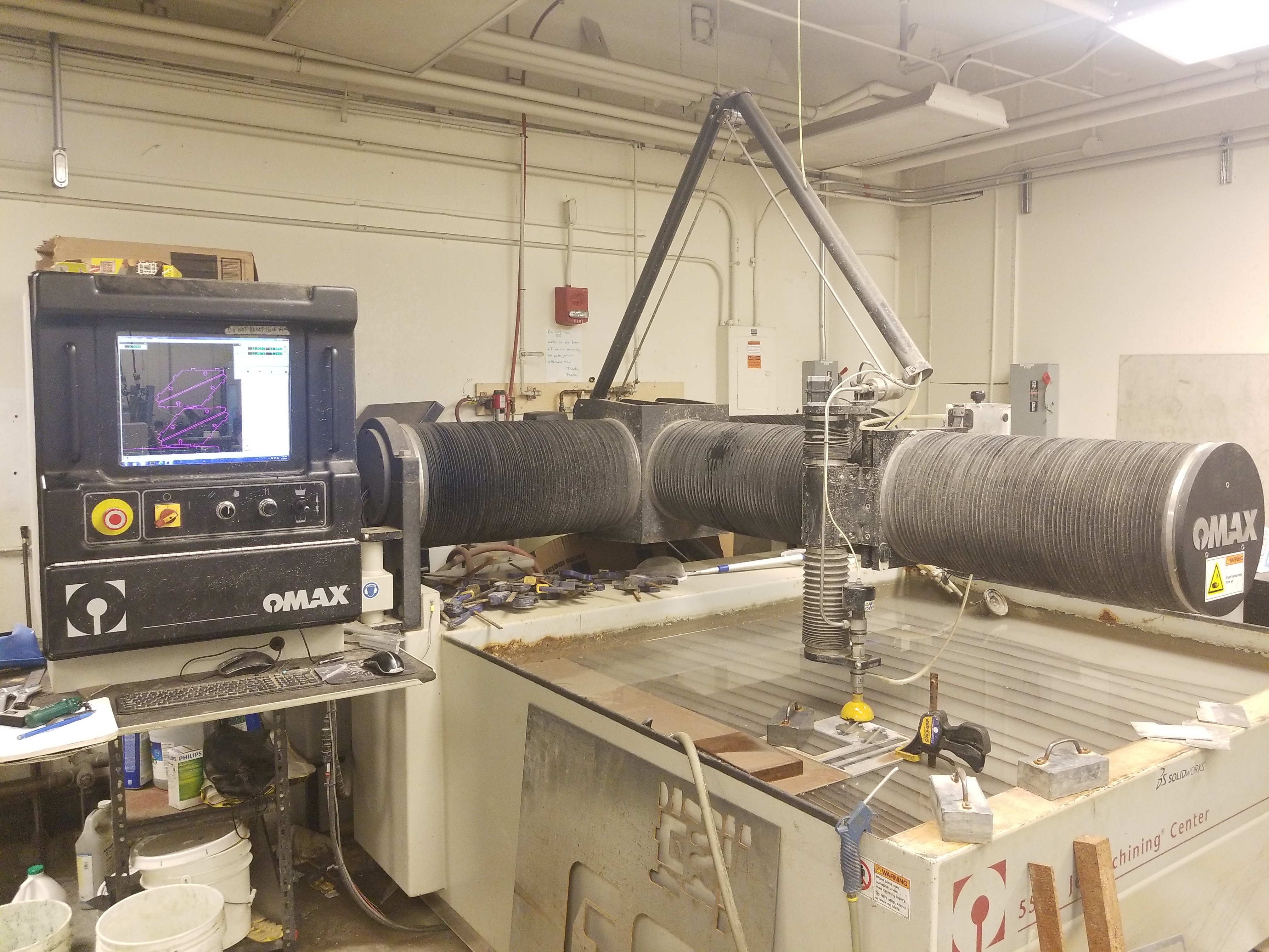
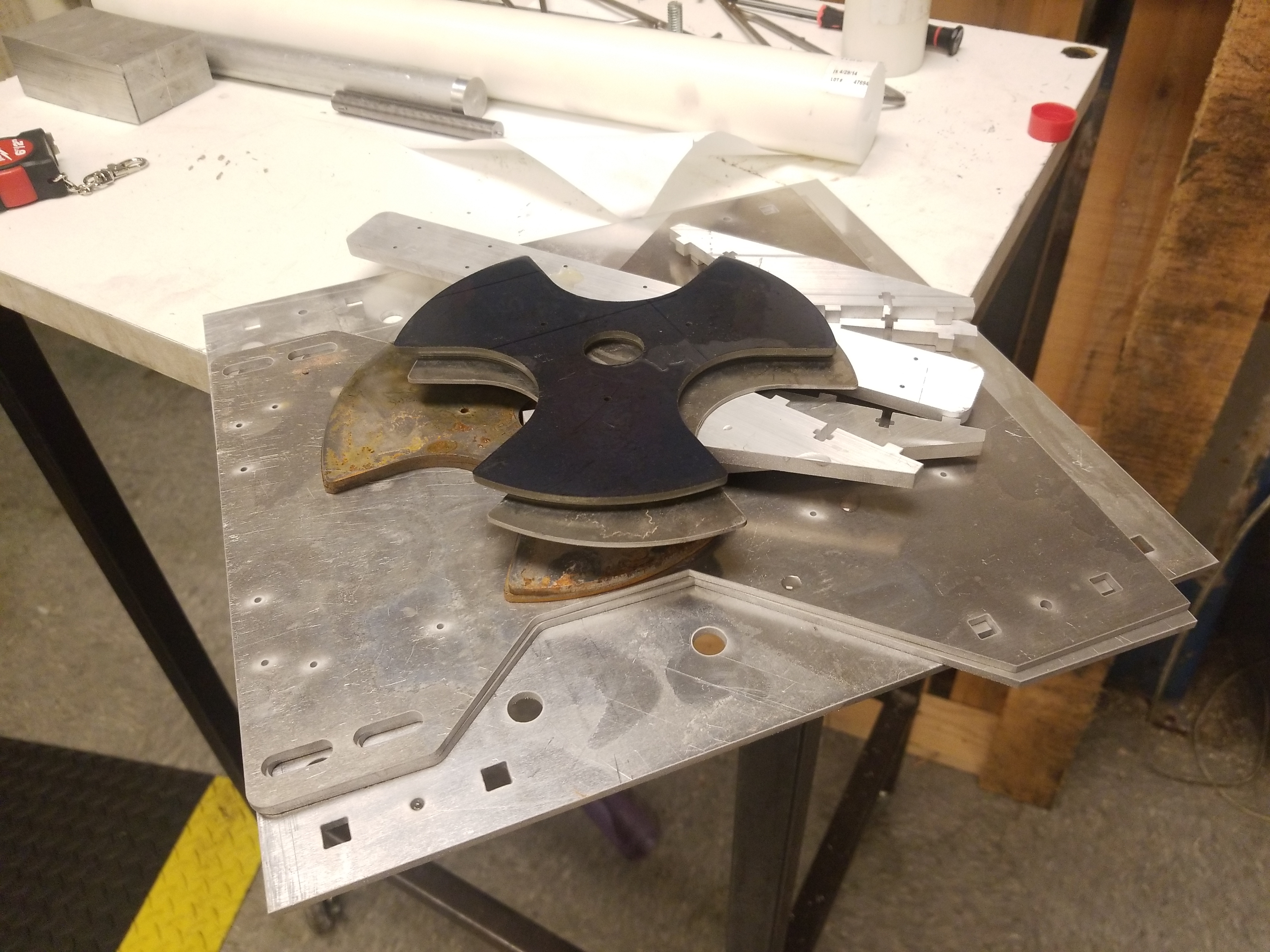
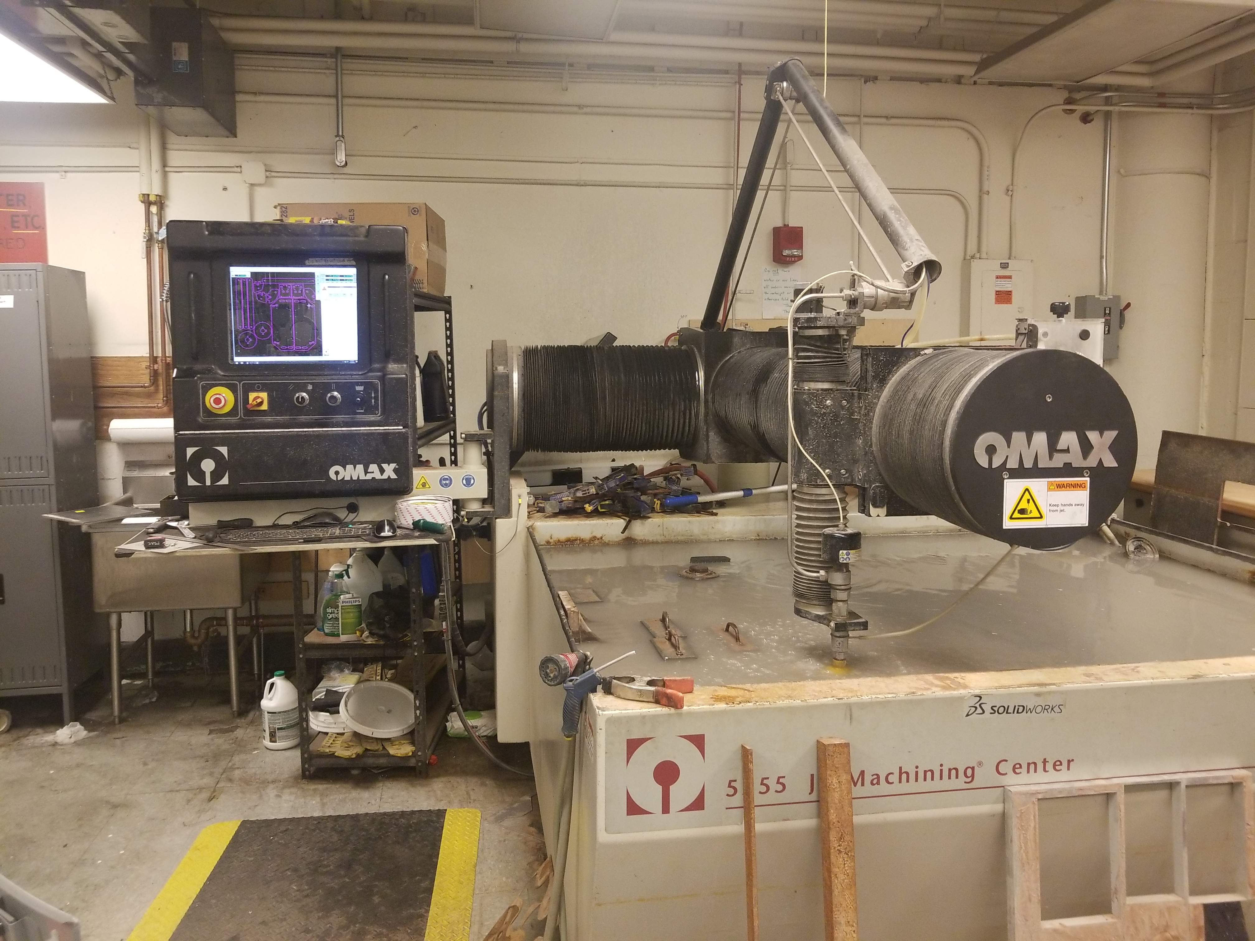
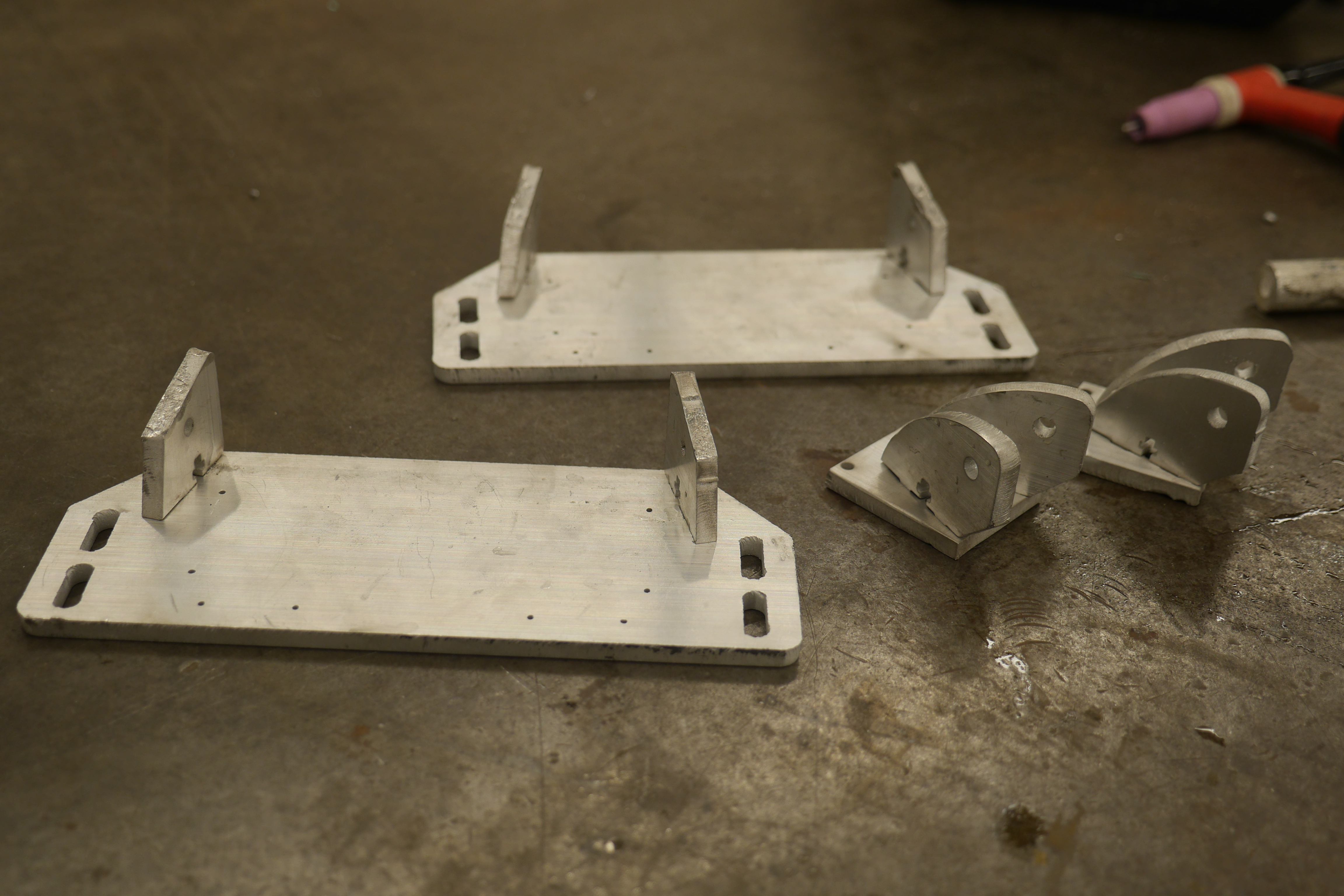
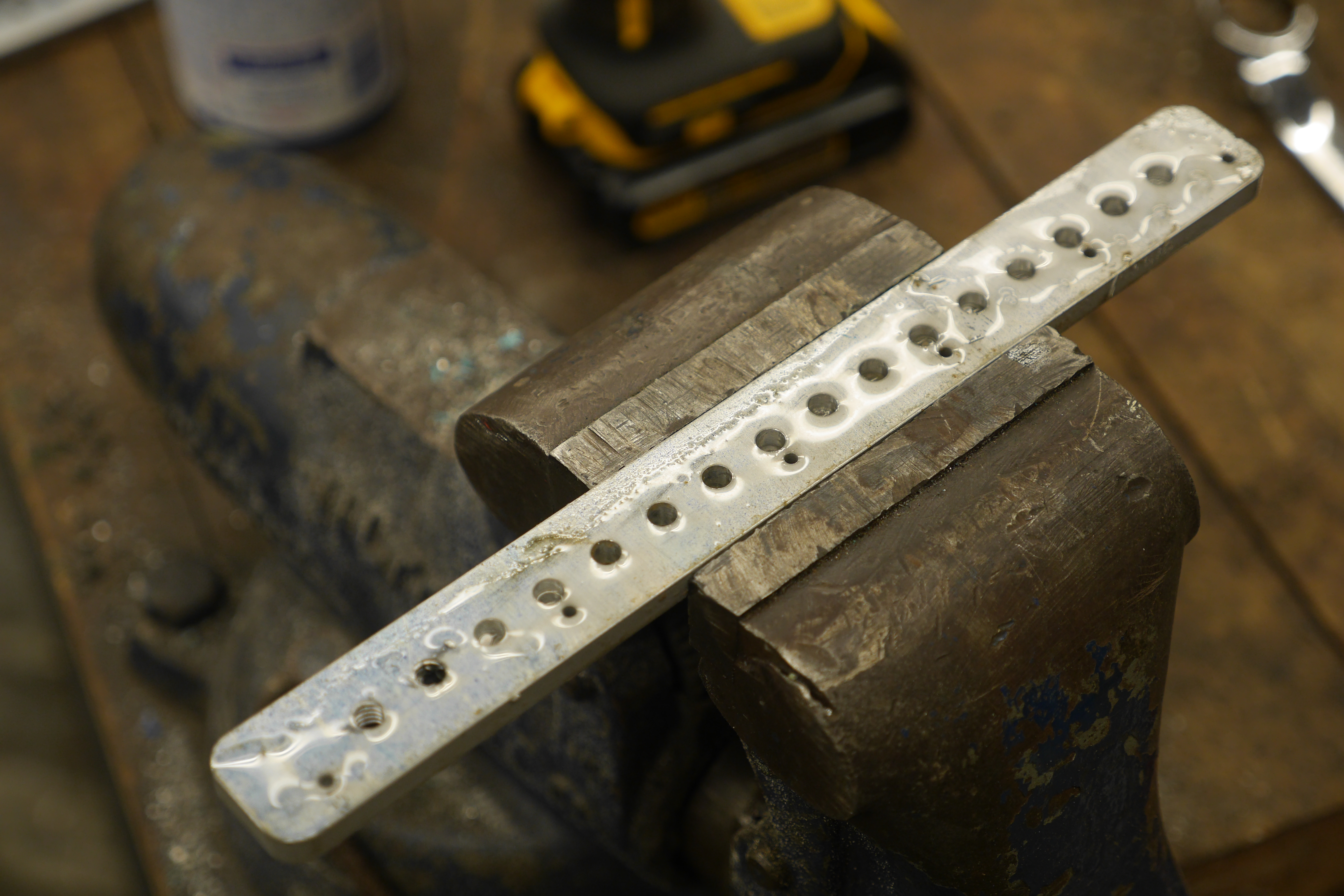
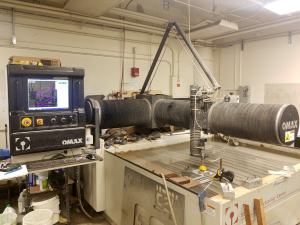
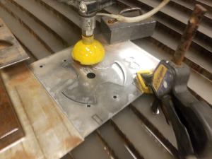
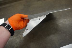
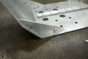
| I
was lucky enough to get some time on the N51 OMAX, and aside from some
flubs, cut out most of the parts for this little beast. Note that the
wheels are front-tires for a lawn tractor so they dont particularly
have a place to mechanically couple torque. To sort out this issue I
opted for adding in ~1/8" steel cut-outs, attached with a few weld
points. Three threaded holes around a central shaft cutout would be
used to transfer torque from a pulley to the wheel. |
 |
 |
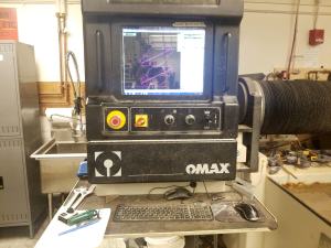
| Waterjet,
oh waterjet solve all of my problems please |
|
|
|
|
|
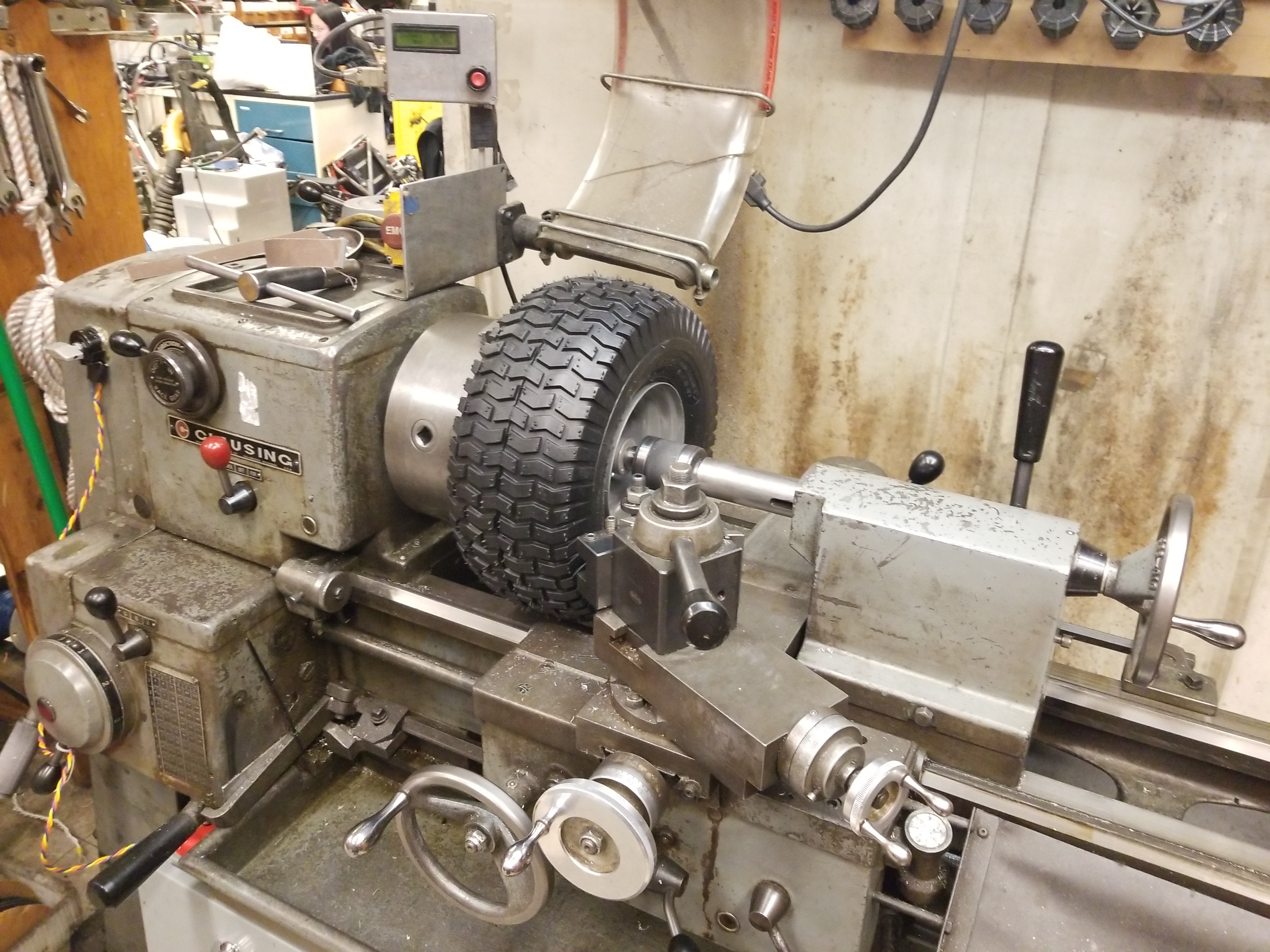
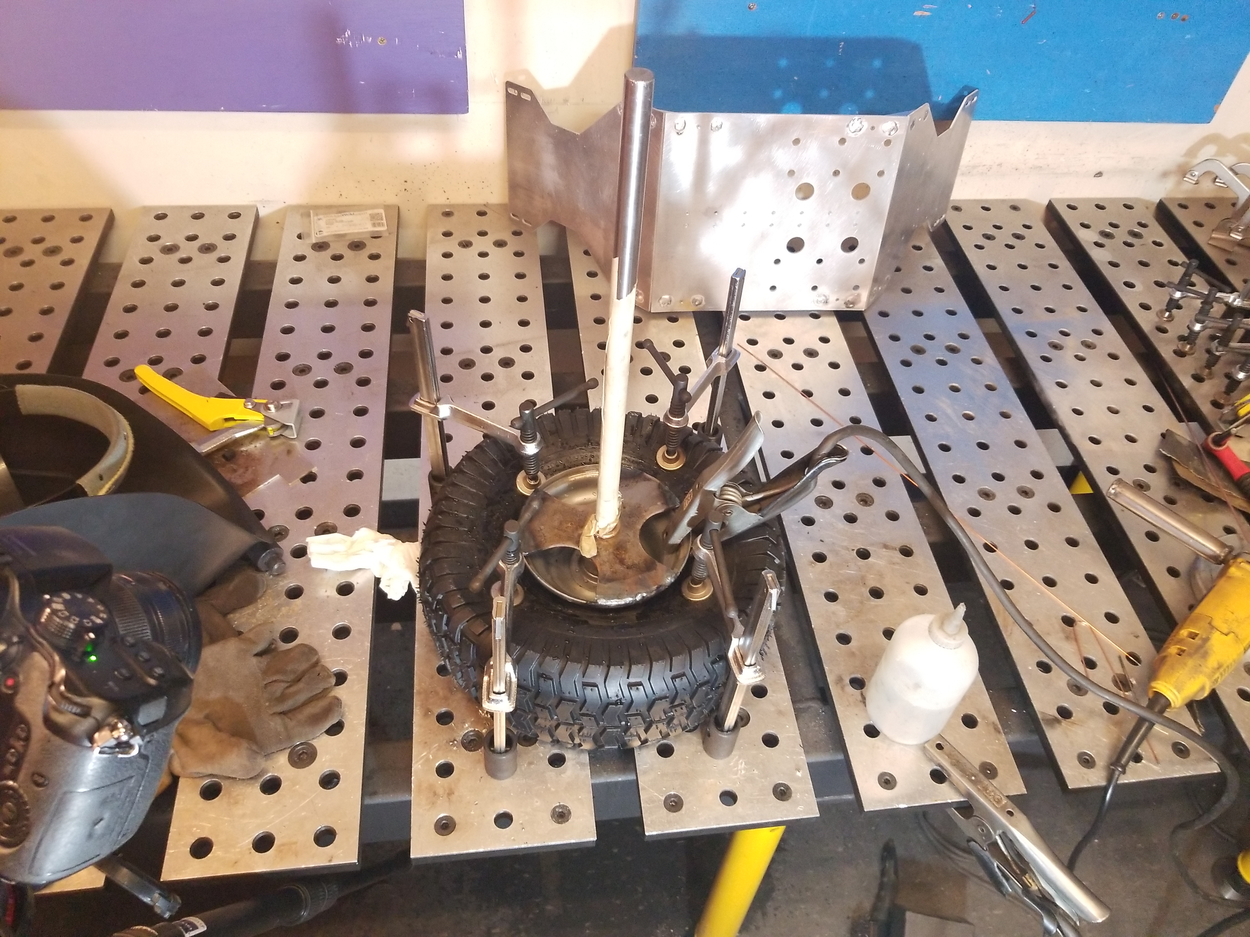
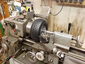
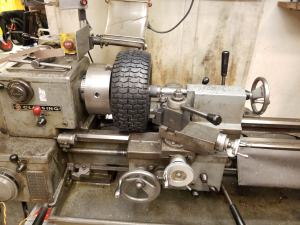
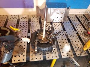
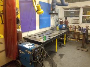
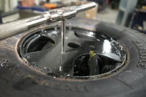
| At
some point in this process i found the paint-removal pre-welding a bit
of a bother. Fortunatley the tire (de-flated) fits nicely inside the
MITERS lathe. I used a 'sandpaper on a stick' tool to quickly de-paint
the inside of the rim assembly to prep for weld. As shown a bunch of
table-clamps are used to keep the tire seperated from the rim to limit
any hot contact between the steel and the rubber. |
 |
|
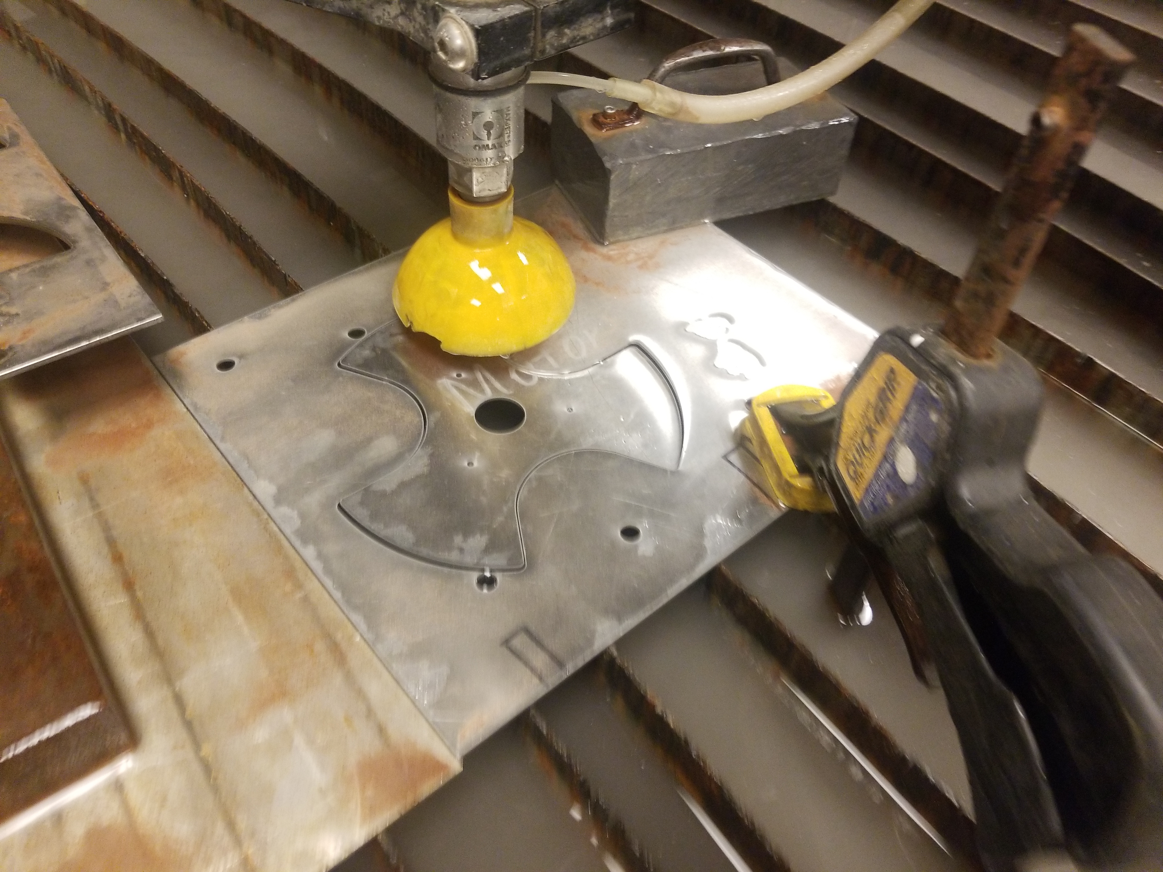
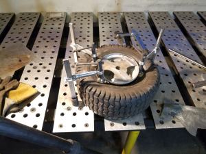
How do you remove these things?
de-beading
small solid rim (non-split) tires is quite a pain. This is nothing like
bicycle tires, so i opted for 'quick low thermal' tig welding to
fixture the torque transfer plate to the rim. Seriously its quite a bit
of effort to replace these things without specalized tooling.
|
 |
 |
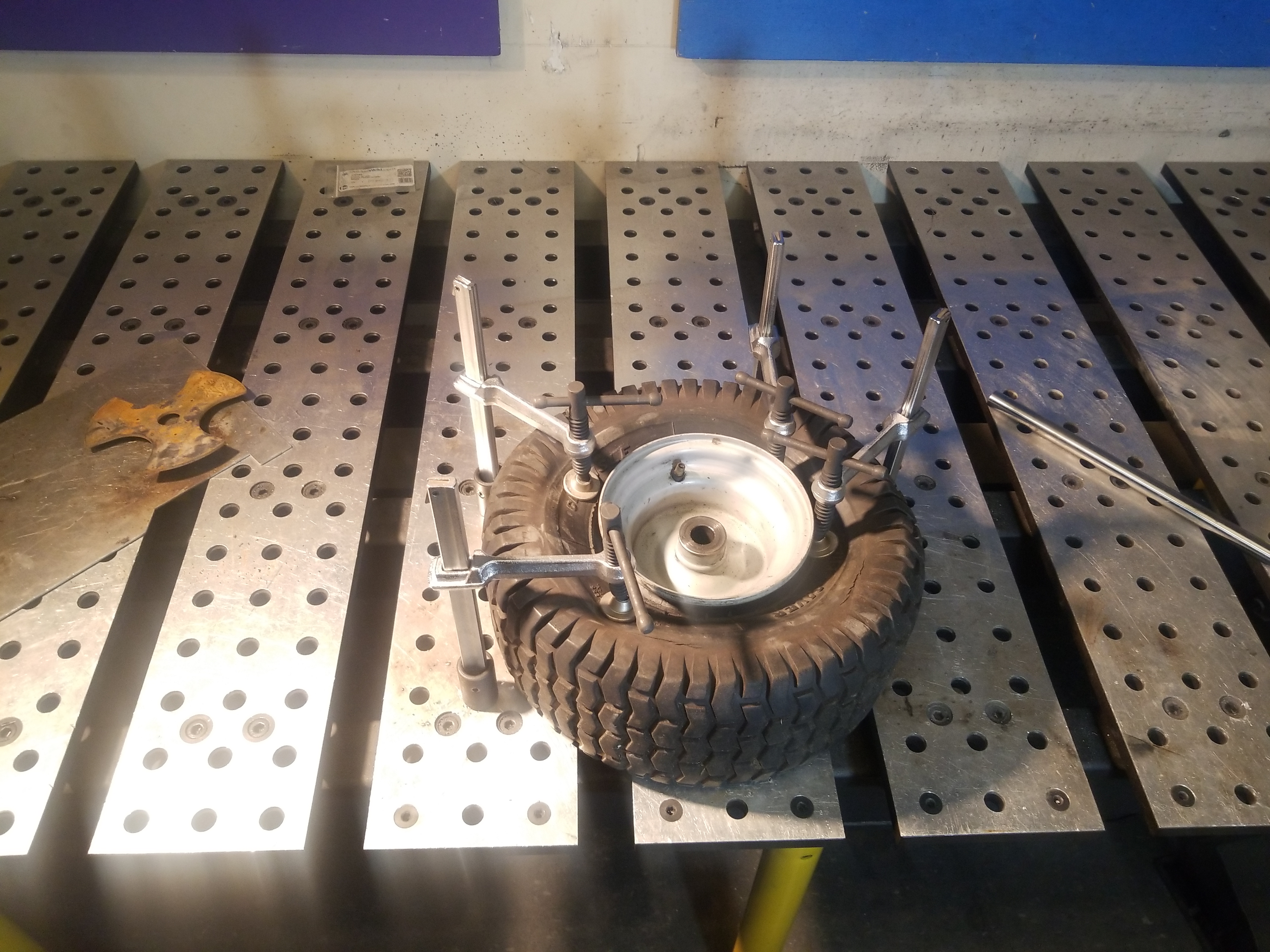
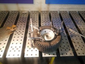
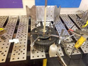
How
do you make sure this thing is centered?
Excellent
question, as making the mounting plate offset would result in uneven
belt tension, and as i was initially hoping for not having a tensioner,
it helps if everything stays co-ordial. As i was using a proper ground
shaft, i designed the wheel adapter to take in a 3/4" bronze bushing,
which when situated between the shaft and pressed into the adapter
plate would make sure the wheel bushings were co-ordial with the
transfer plate. This was left installed during welding to ensure
concentridicty. To prevent weld splatter from ruining the shaft, I
covered it with masking tape, which did a reasonable job of keeping the
shaft clean. |
 |
 |
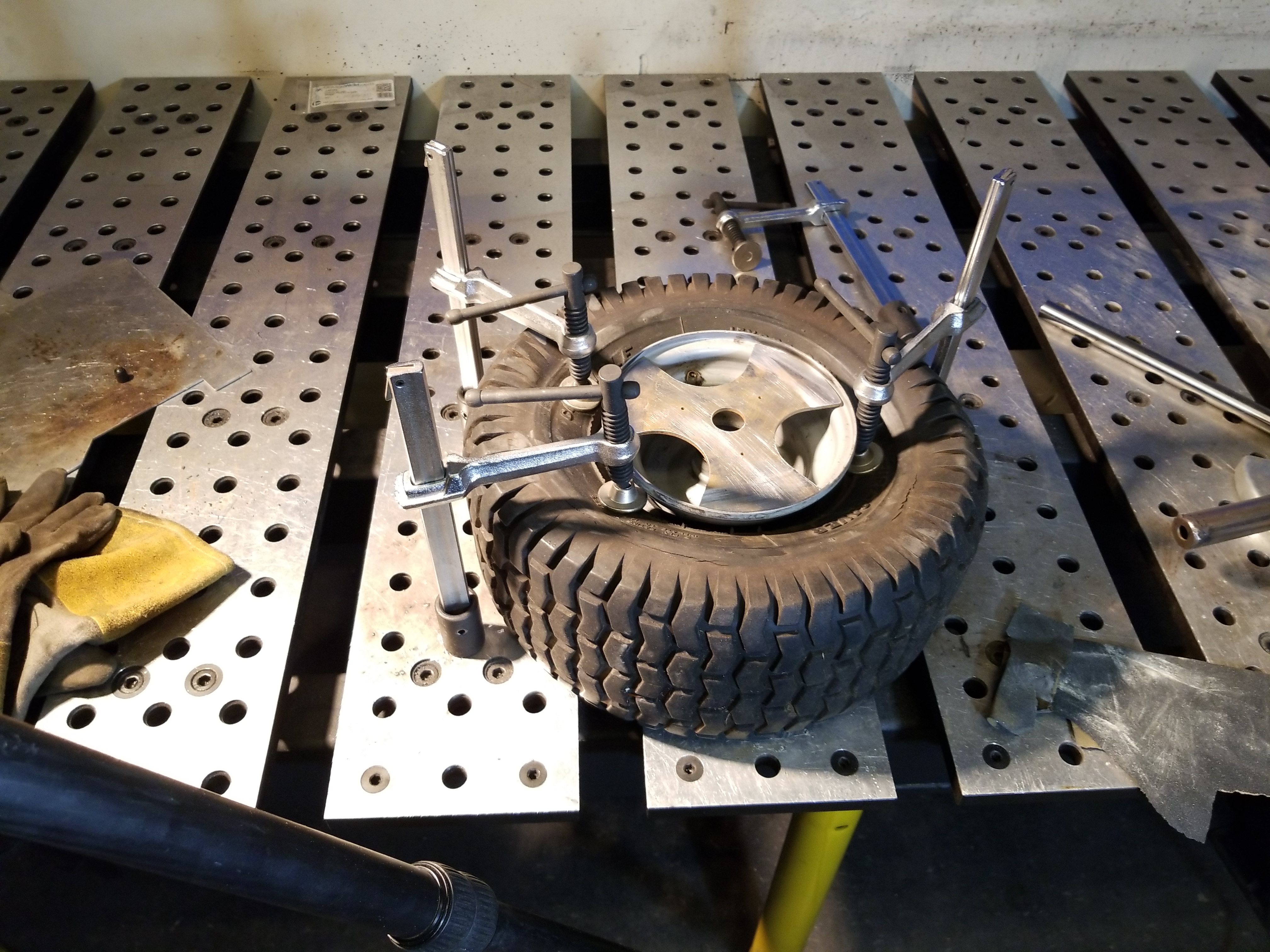
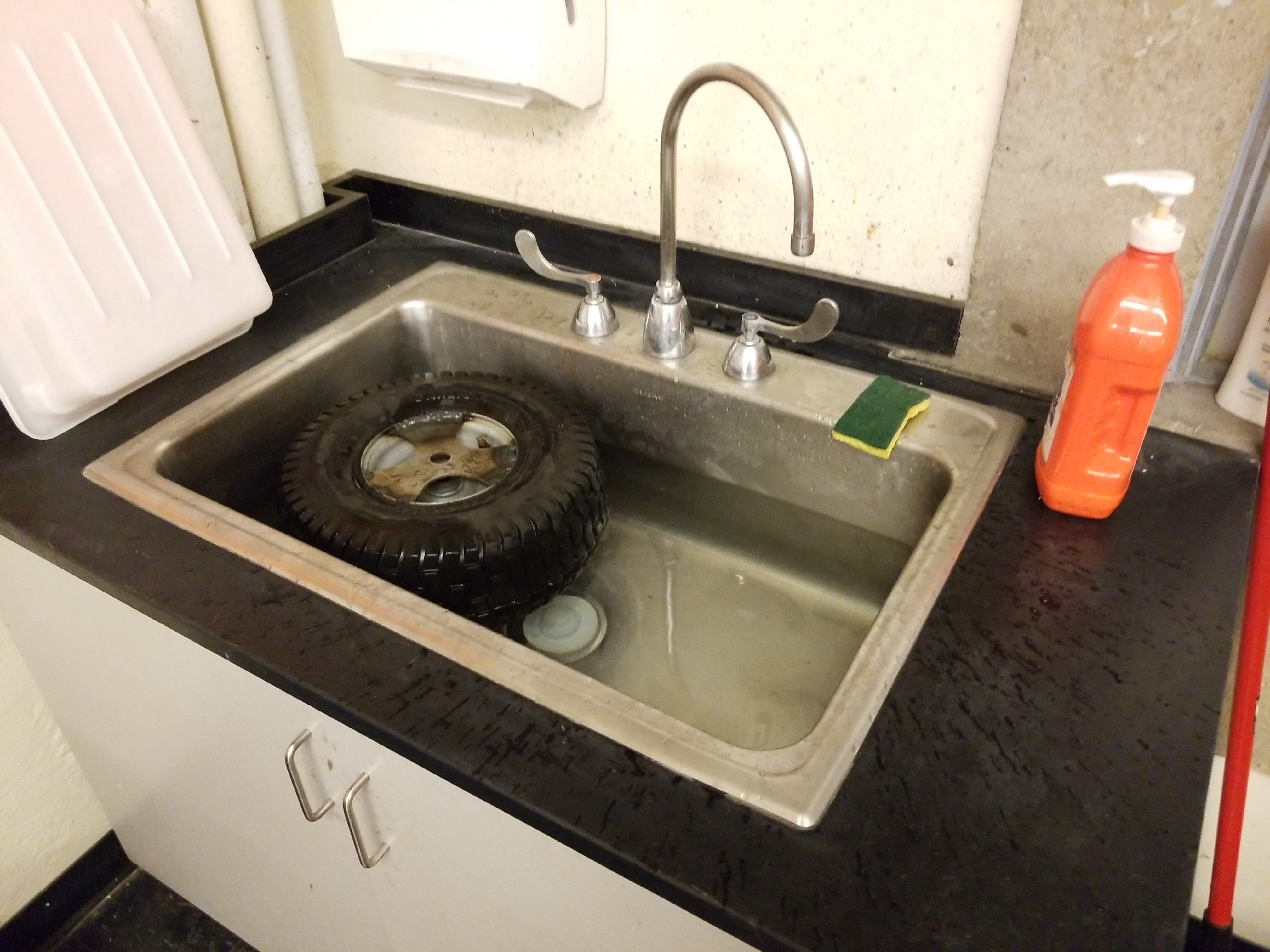
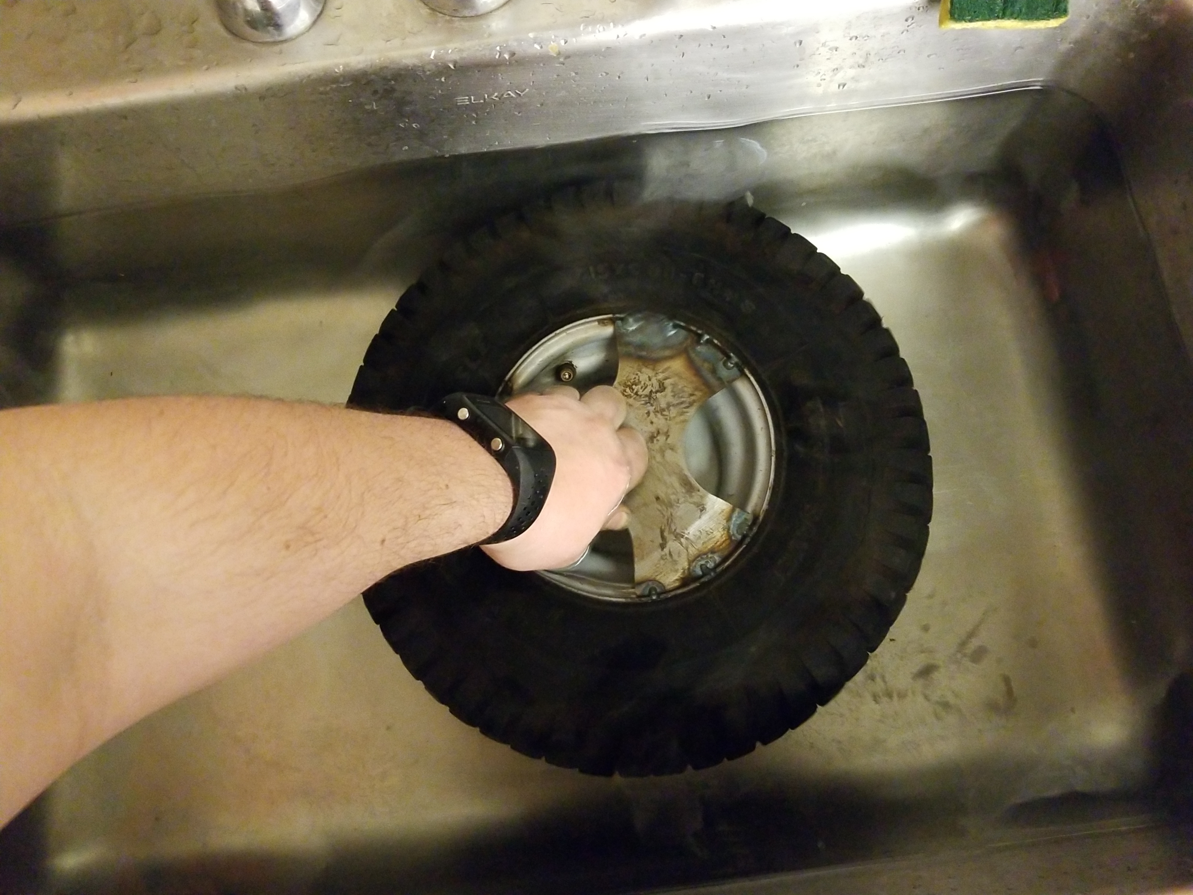
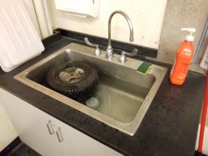
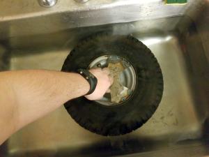
Now
repeat that three more times.
It was actually
hard to not fully
weld the mating surface as i'm so used to not leaving just tack welds
on projects. To make sure everything was actually working I did a quick
sink test. With the tire fully submerged and held down with a hand I
checked for bubbles. I was incredibly surprised that the whole welding
and smushing process showed no leaks. Unfortunatley I had just taken
bare steel and covered it immediatley in water, which is a wonderful
way to have rusty wheels. The bushings also probably didnt benefit much
from being submerged. |
 |
 |
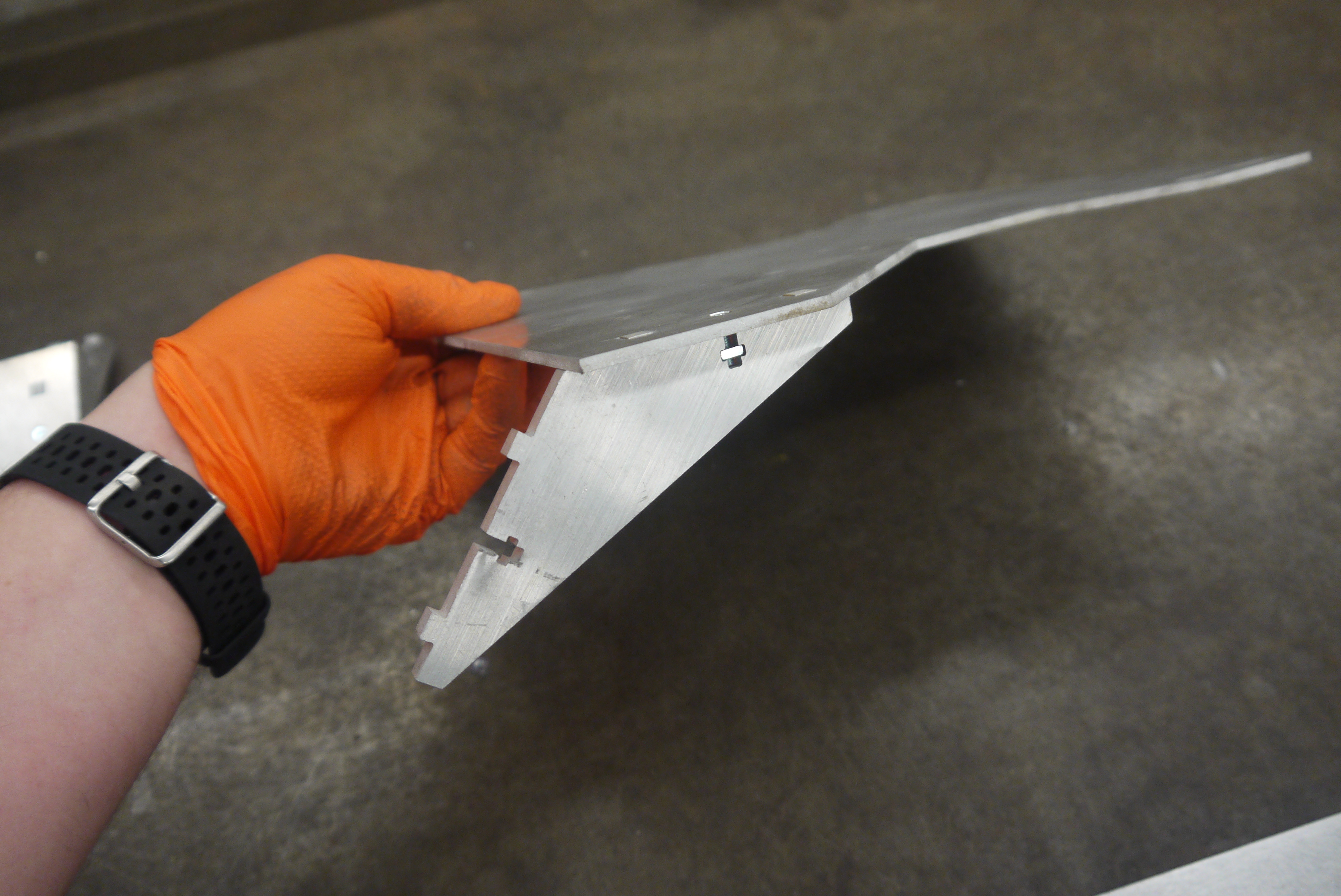
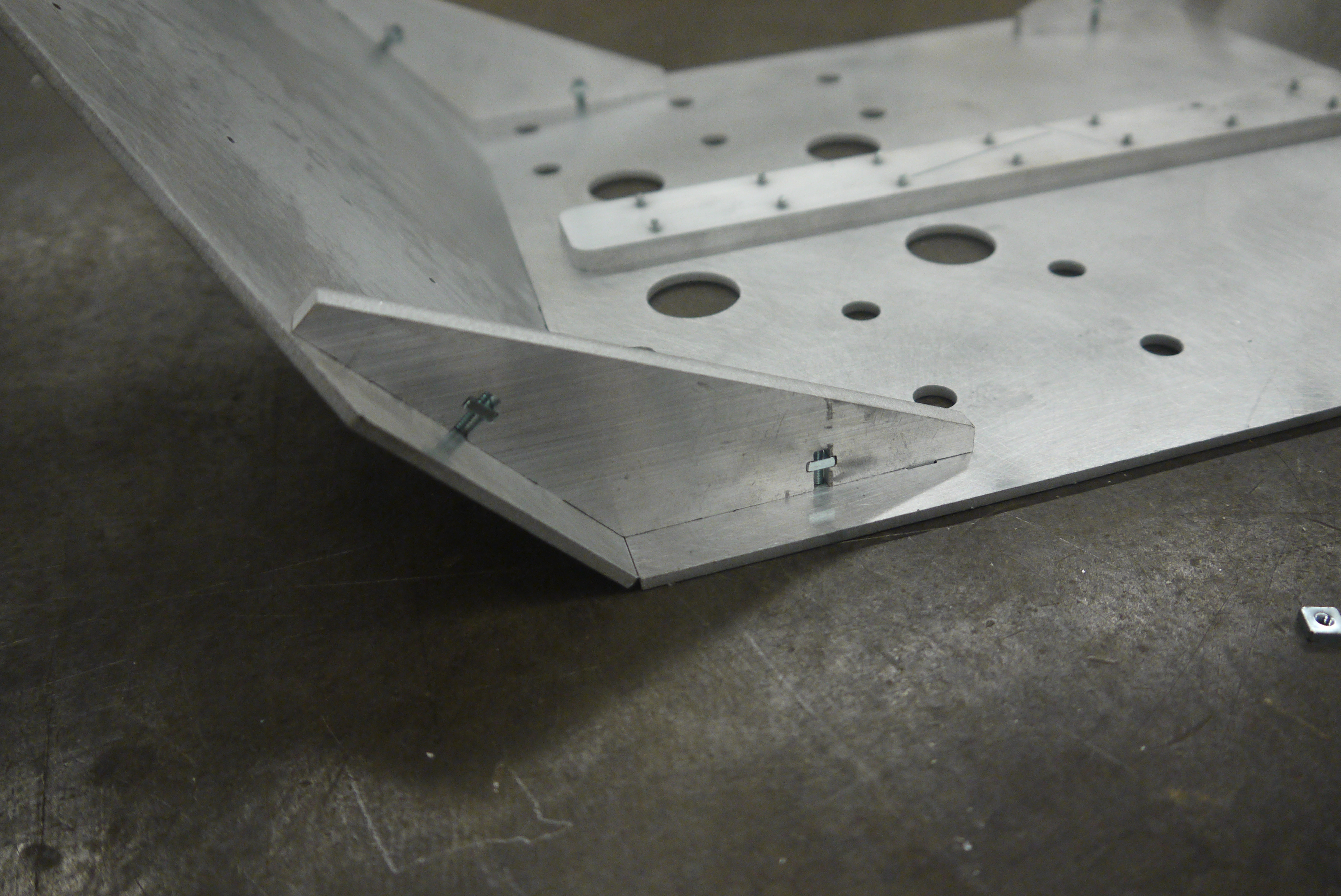
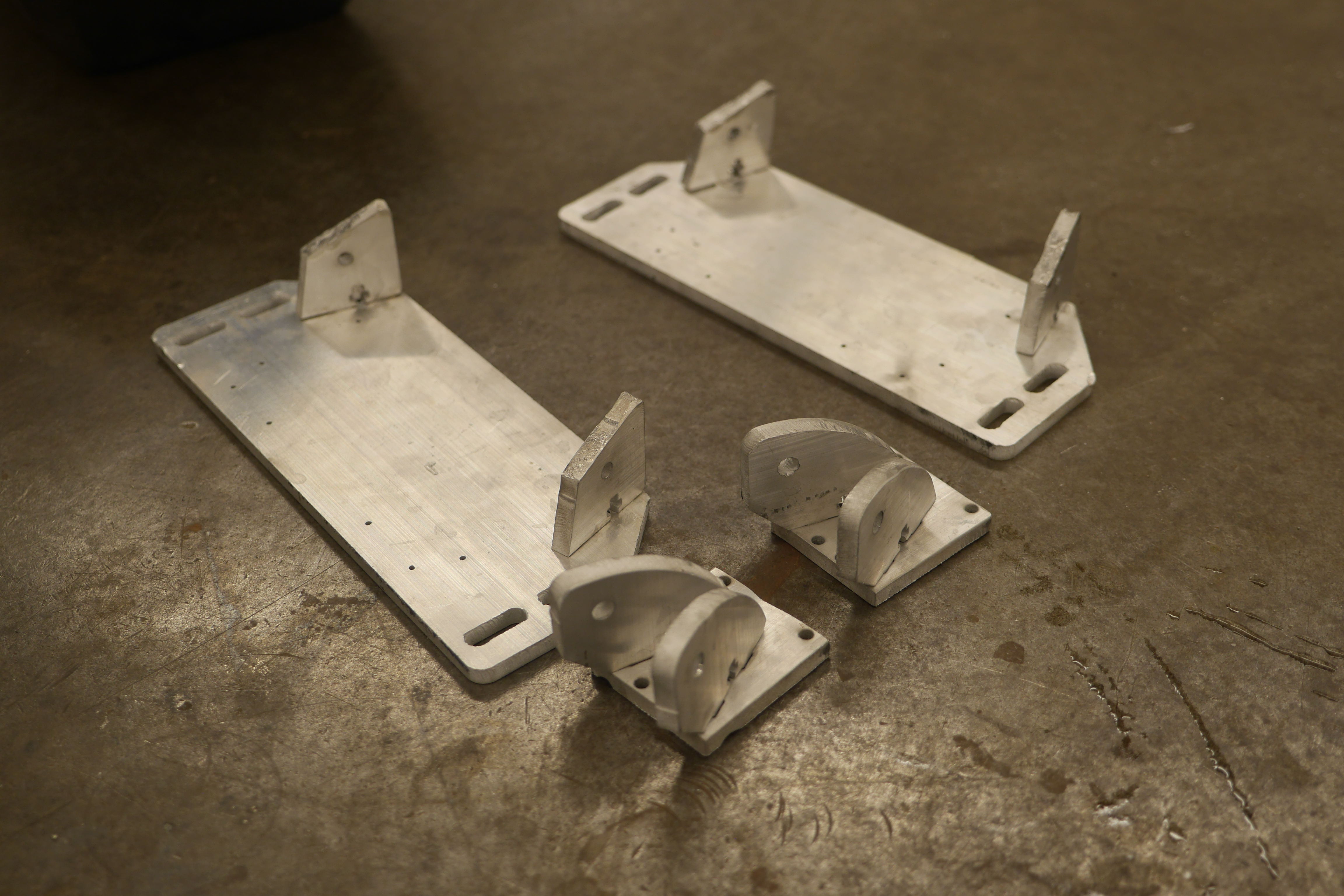
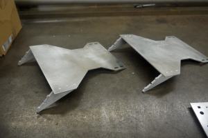
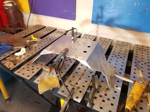
Now
onto the frame.
To
make my assembly easier I opted for a (mostly) captured nut and 4-40
screws to assemble the sides. How does this work you ask? the puzzle
shaped 1/4" thick aluminum cut out fits into matching square holes in
either plate, then a t-shaped cut out fits a 4-40 square nut. A
recessed 4-40 screw constrains the assembly in all 3 directions and is
great for quick mounting. The big benefit to this is not having to drill and tap holes
as the steel nut has more holding force than the equivalent depth
tapped aluminum hole. |
 |
 |
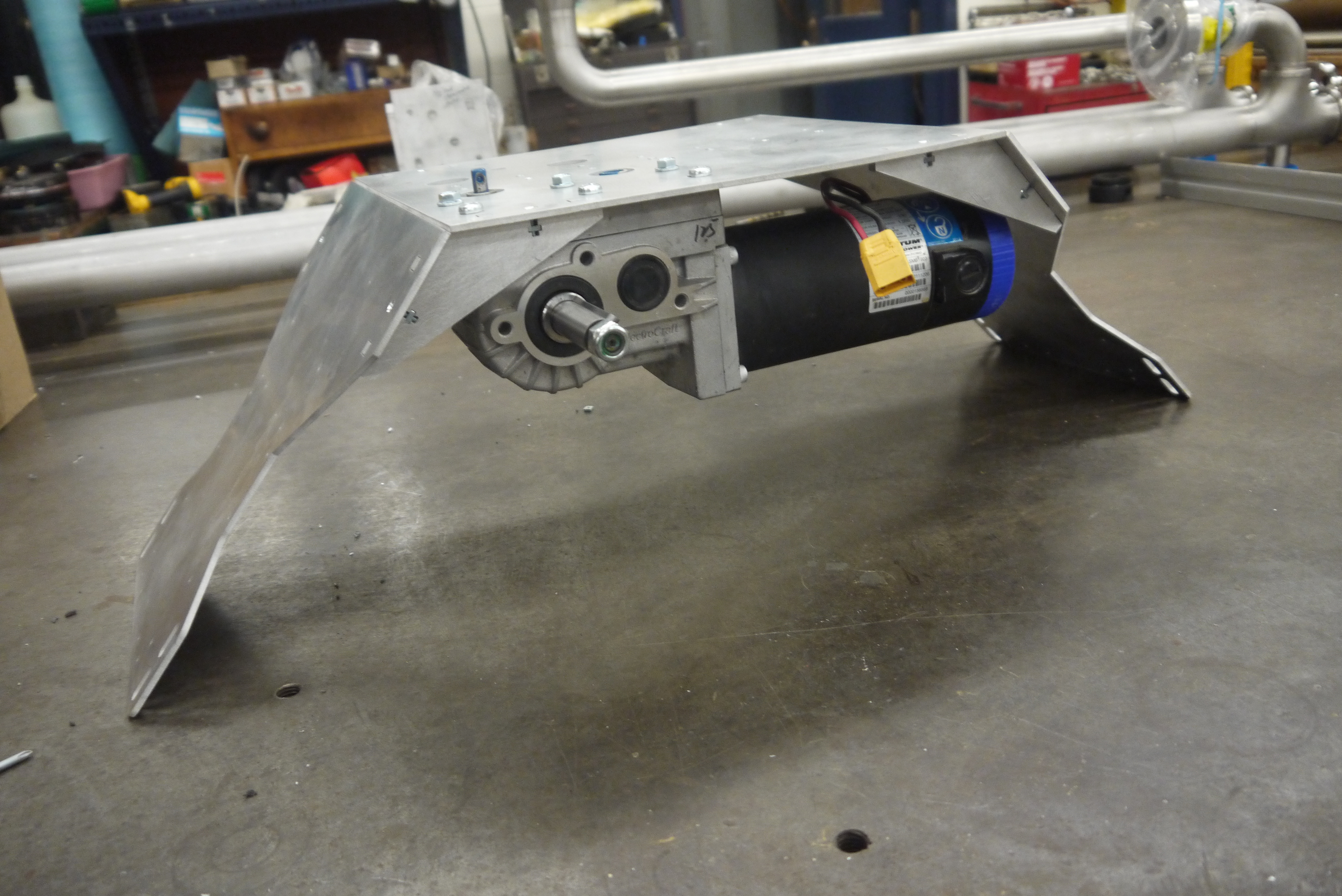
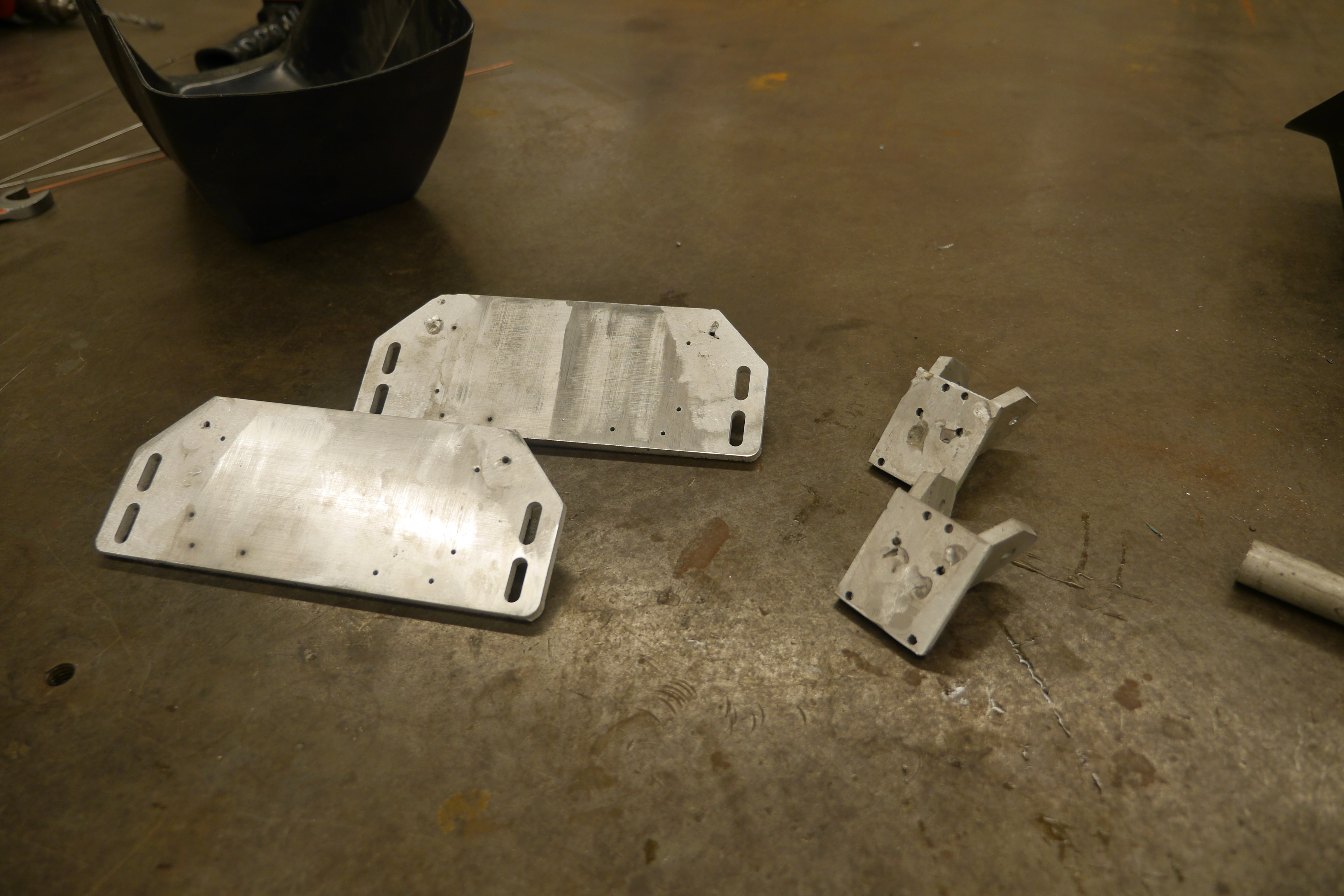
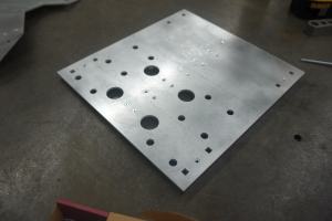
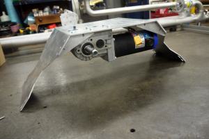
| Comically
i did not have any spare 1/4" plate so i opted for using 1/8" thick
plate as the base / wheelchair motor mounts and added a 1/4" stiffener
plate to the underside. This nominally acts as a spine and prevents the
whole assembly from being flexible about the middle. Shown is the
swiss-cheese top plate with large holes for each wheelchair motor mount
along with the small 4-40 screws bolted into the 1/4" tapped stiffener
plate. |
 |
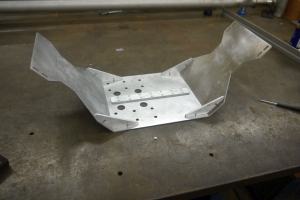 |
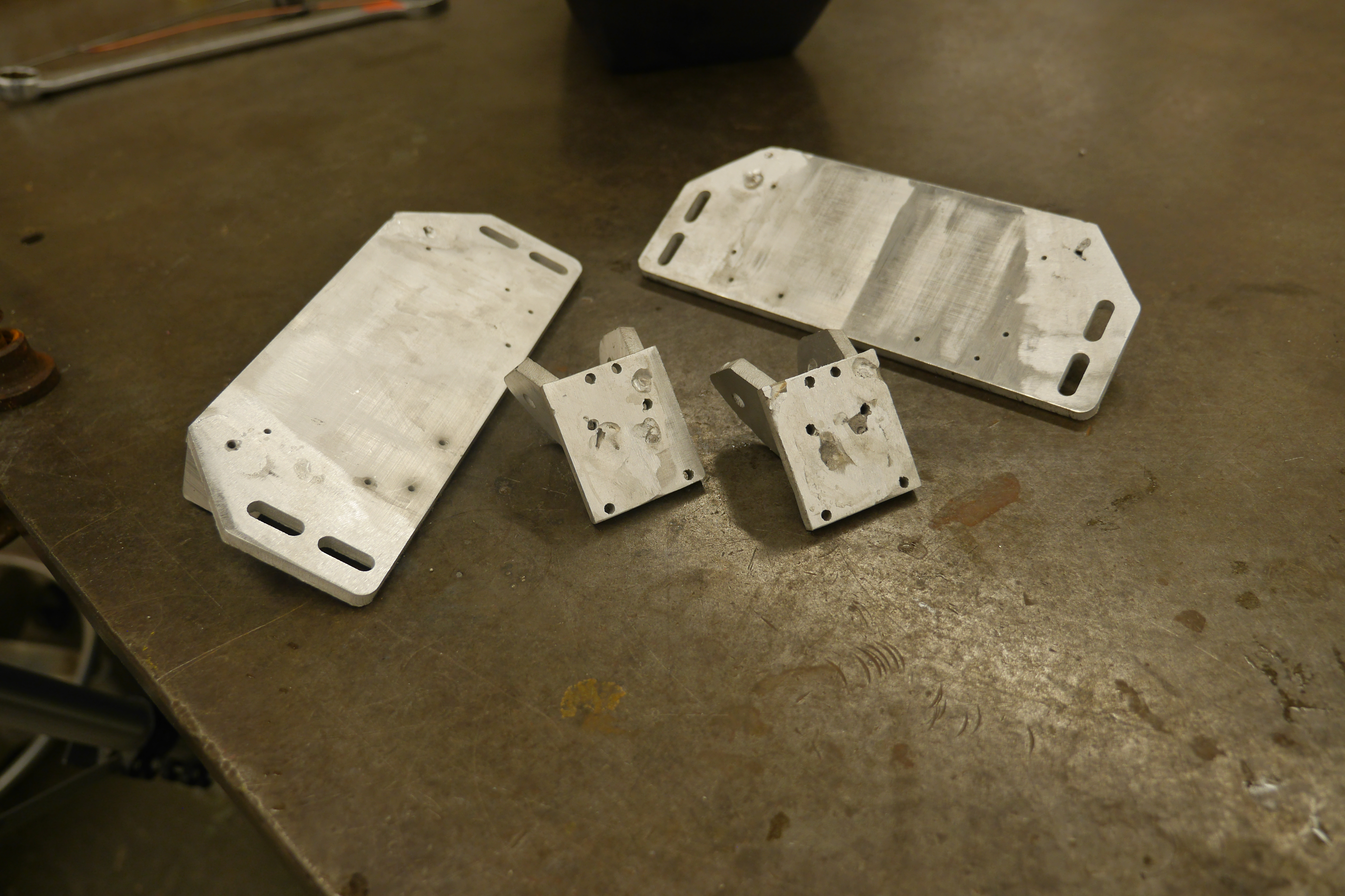
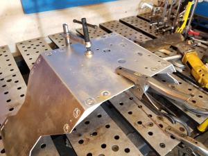
| Here's
an up-close shot of this assembly. Nominally this works well for an
arbitrairy plate thickness, assuming an associated square-nut exists. I
was a little wary with the holding force of just 4-40 screws, so i
opted to just use this as jigs for holding the frame together and weld
the square cutouts to ensure the rover didn not 'rapidly disassemble'
during roving. Before welding I opted to mount the wheelchair motor
temporairally to ensure everything fit. Its fairly comical how much
heavier the motor assemblies are versus the frame, but i was opting for
'low speed & light weightish' over 'giant steel box-frame
thing' |
 |
 |
Lets
weld
Tig
welding 1/8 to 1/4" aluminum is not terrible, as each material has a
different thermal mass, its important to pre-heat a bit before going to
town with the tig torch. I generally opt for running the torch at
20-30A with the arc running and dance it around the area that will be
welded. This has the added bonus of heating and slightly cleaning the
area in question. If there is signficant surface contamination the
torch will tell you. With the surface warmed up its also way easier to
start welding. In this case i started with the 1/4" insert cutout and
worked my way to the 1/8" plate. |
 |
 |
With the frame now one giant
aluminum assembly, its time to cleanup and try and prevent those tires
from rusting immediatley.
A clean welding bench is a happy welding bench :] Special
thanks to DLAB jack for such a wonderful welding space. |
 |
 |
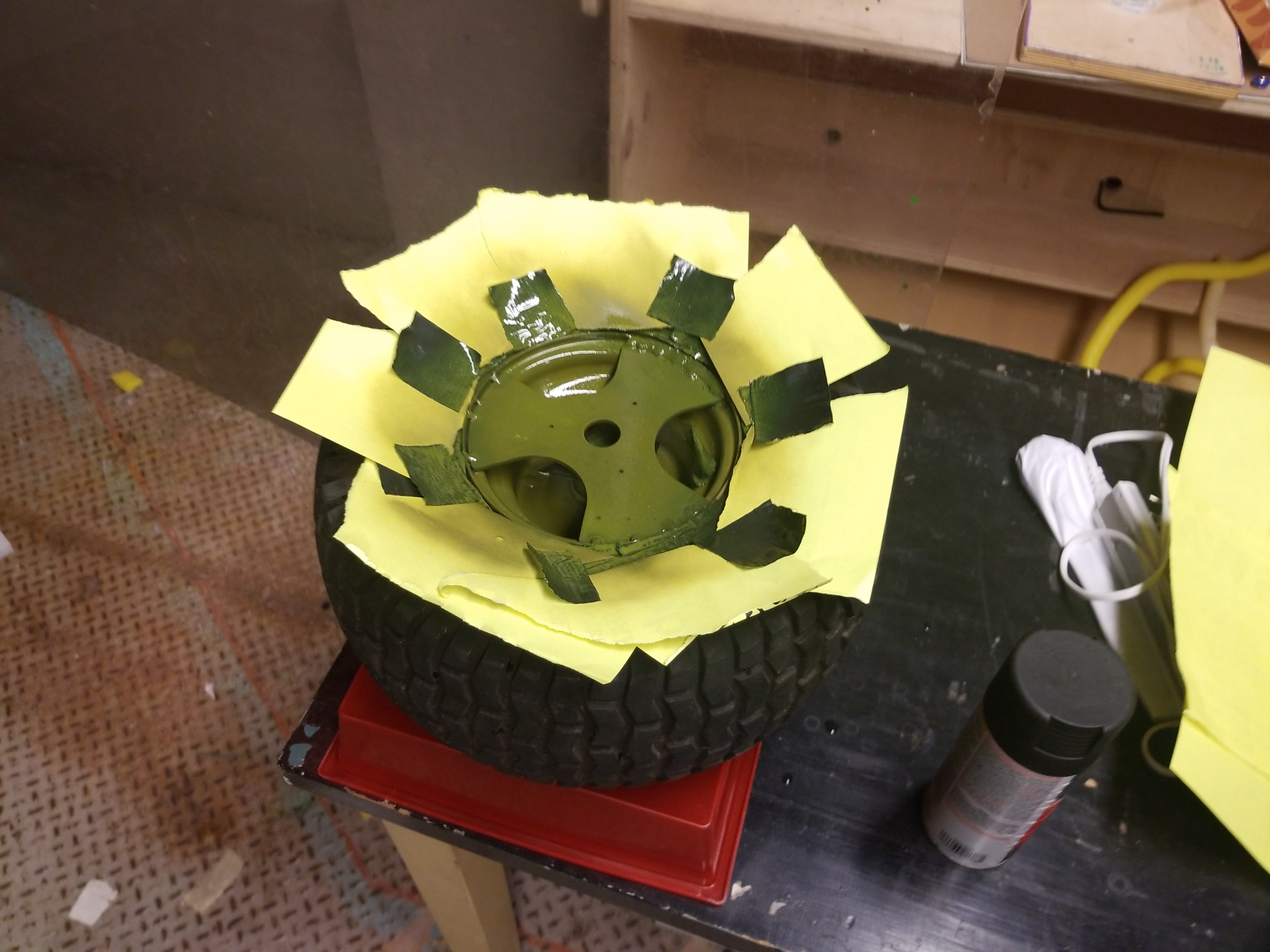
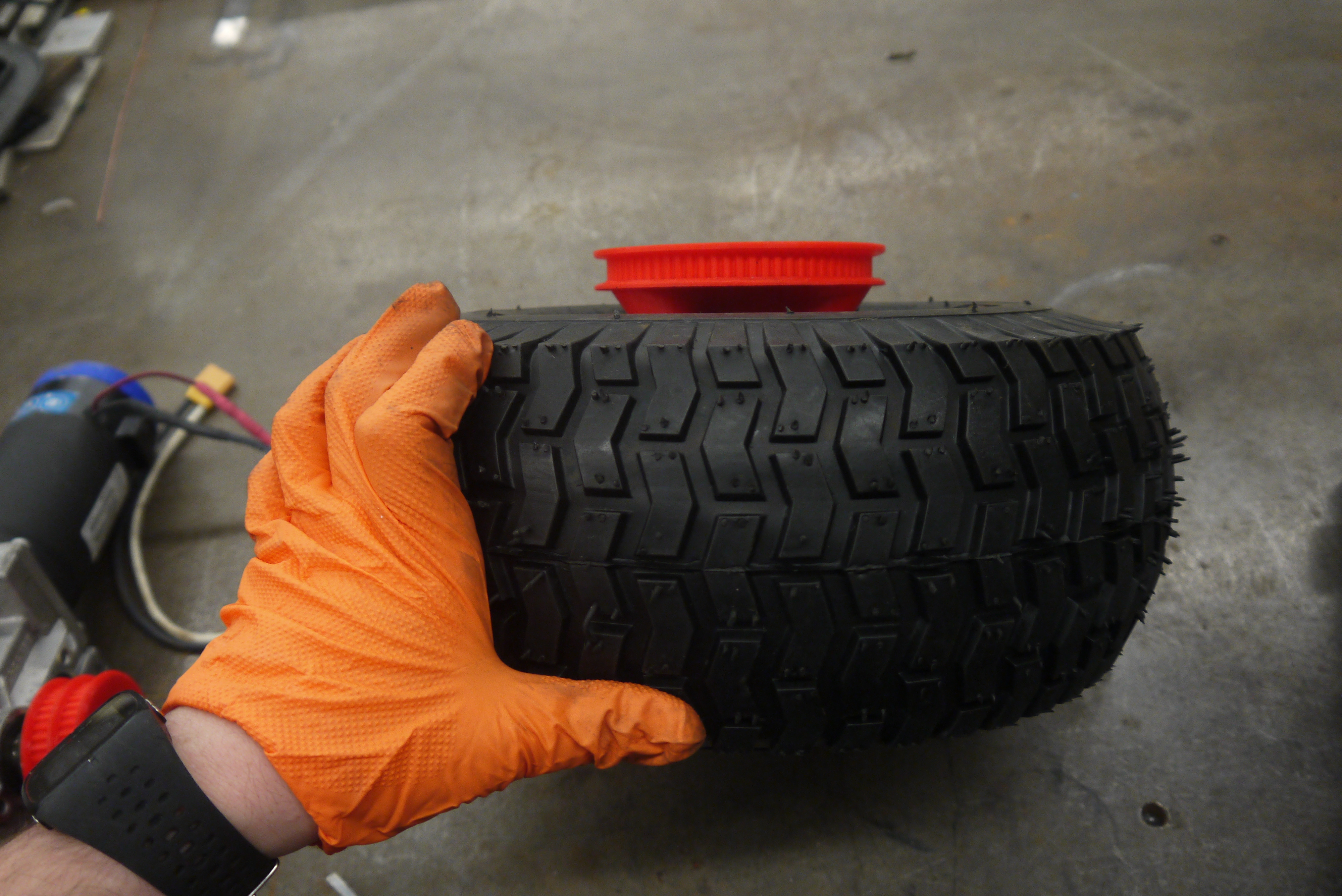
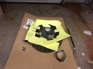
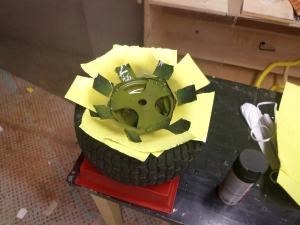
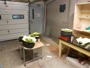
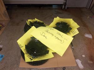
| Lets
prime and weld up some wheels. To prevent the tires from getting
covered in primer and paint, I used some recycled printouts and tape to
make a mask around the area to be painted. Tape was applied to prevent
the valvestem and center bushing from getting paint debris. I started
with two coats of zinc based primer, and managed to find enough space
to paint all four tires during the same evening. |
 |
 |
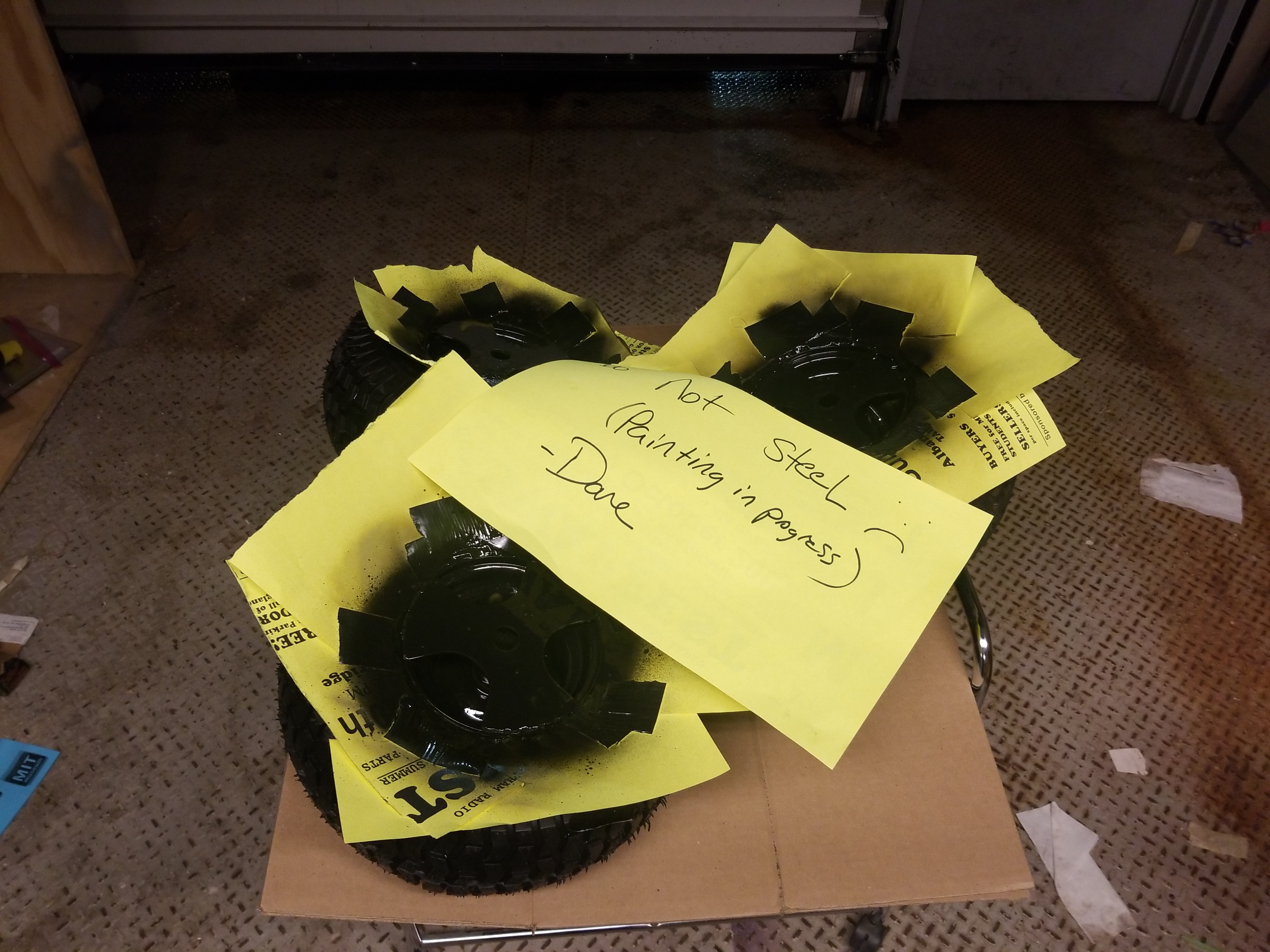
| After
2 hours of setup, i finished with a coat of what was supposed to be
matte black, and let them dry in a warm server room overnight. |
 |
 |
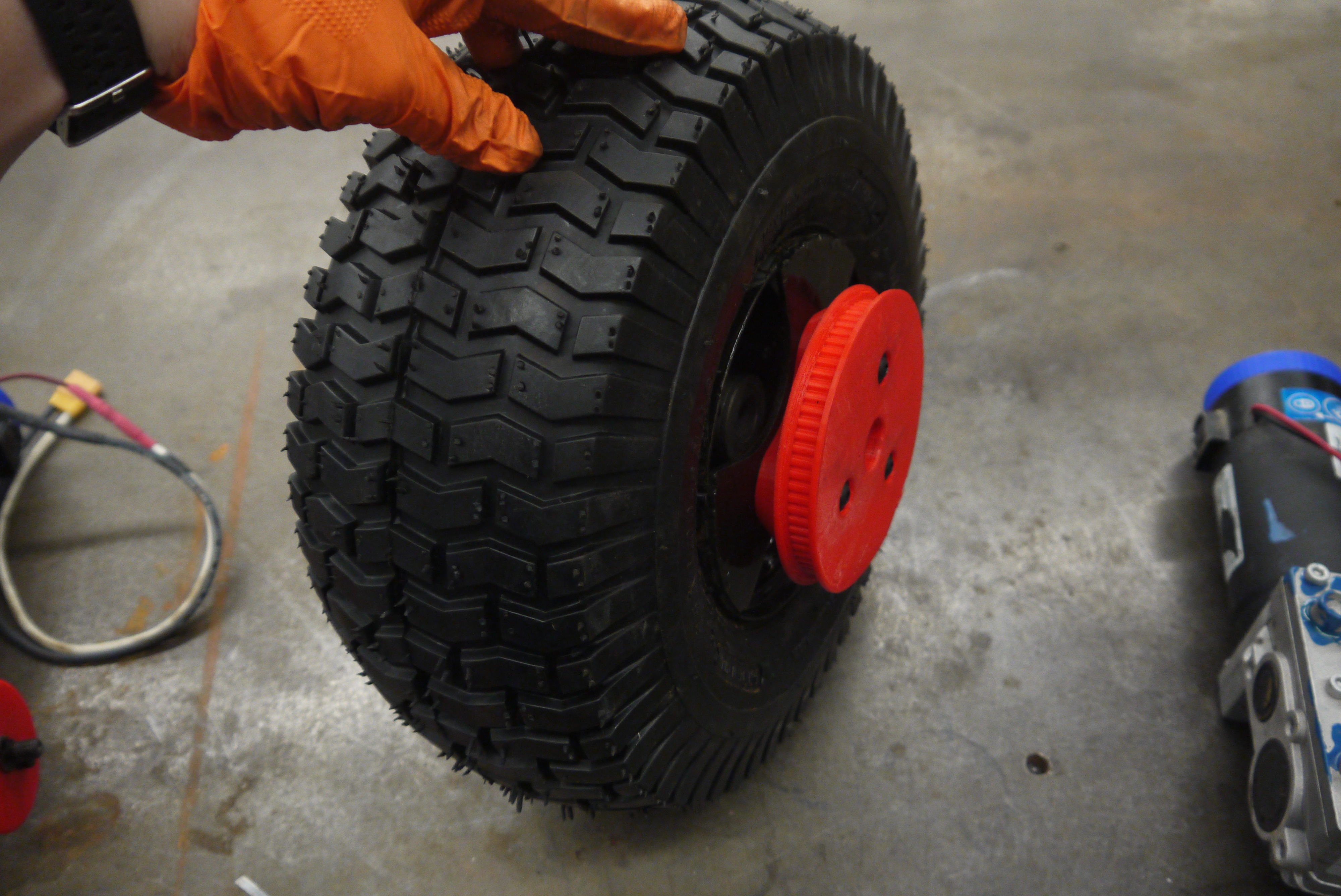
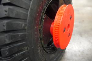
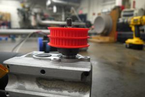
I used the evening to print out
a few wheel-timing-belt adapters.
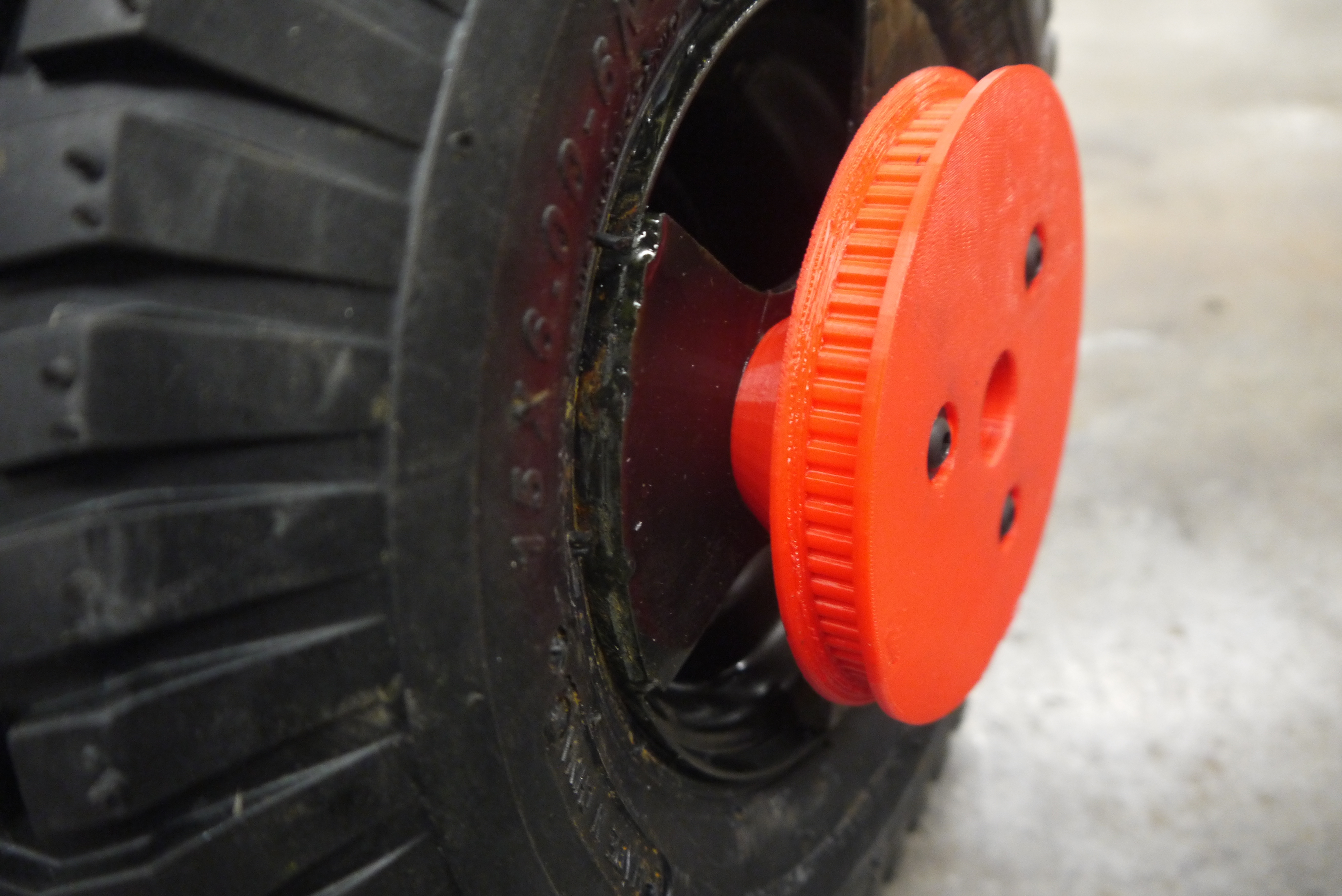
These
are 3d printed parts that transfer motor torque from the wheelchair
motor to each wheel. Force is coupled through three 1/4-20 flat socket
head cap screws. The prints were intentionaly dense as i was
hoping to not run into issues with these failing under duress. |
|
|
Time
to tap some holes.
As
was hopefully visible earlier, each wheel-hub adapter plate had three
small centering holes, each of which needs to be drilled out and tapped
to accept the adapters. As the drilling process was mostly a 'setup the
drill press and go to town' the tapping was a bit slower. With the
wheels tapped, it was now time to test out the timing belt adapters. |
 |
 |
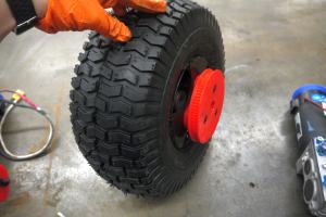
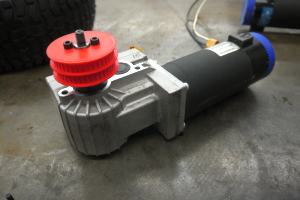
| With
the pulleys printed i removed associated support material and added the
three 1/4-20 screws. Note that for the sake of testing I did not |
 |
 |
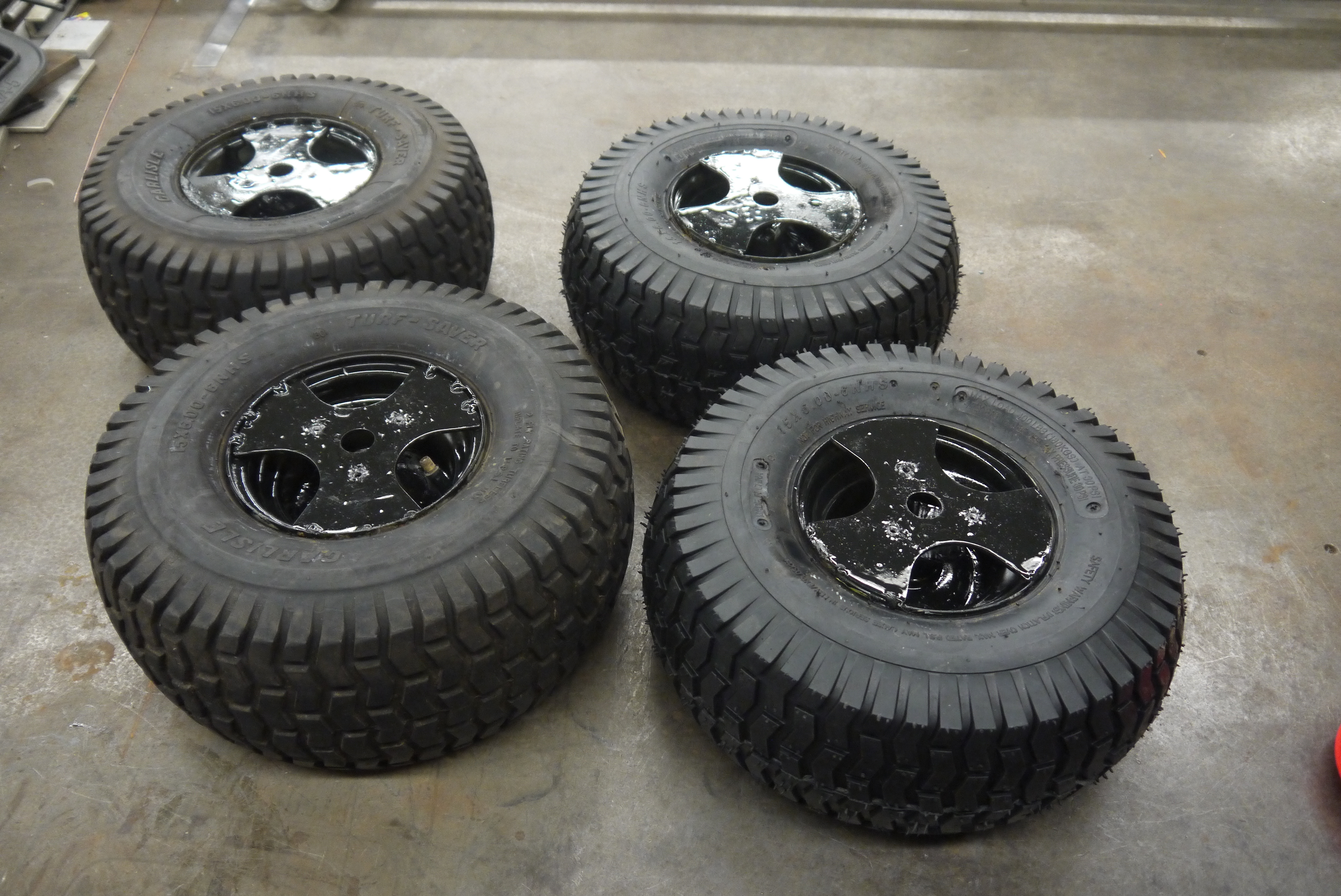
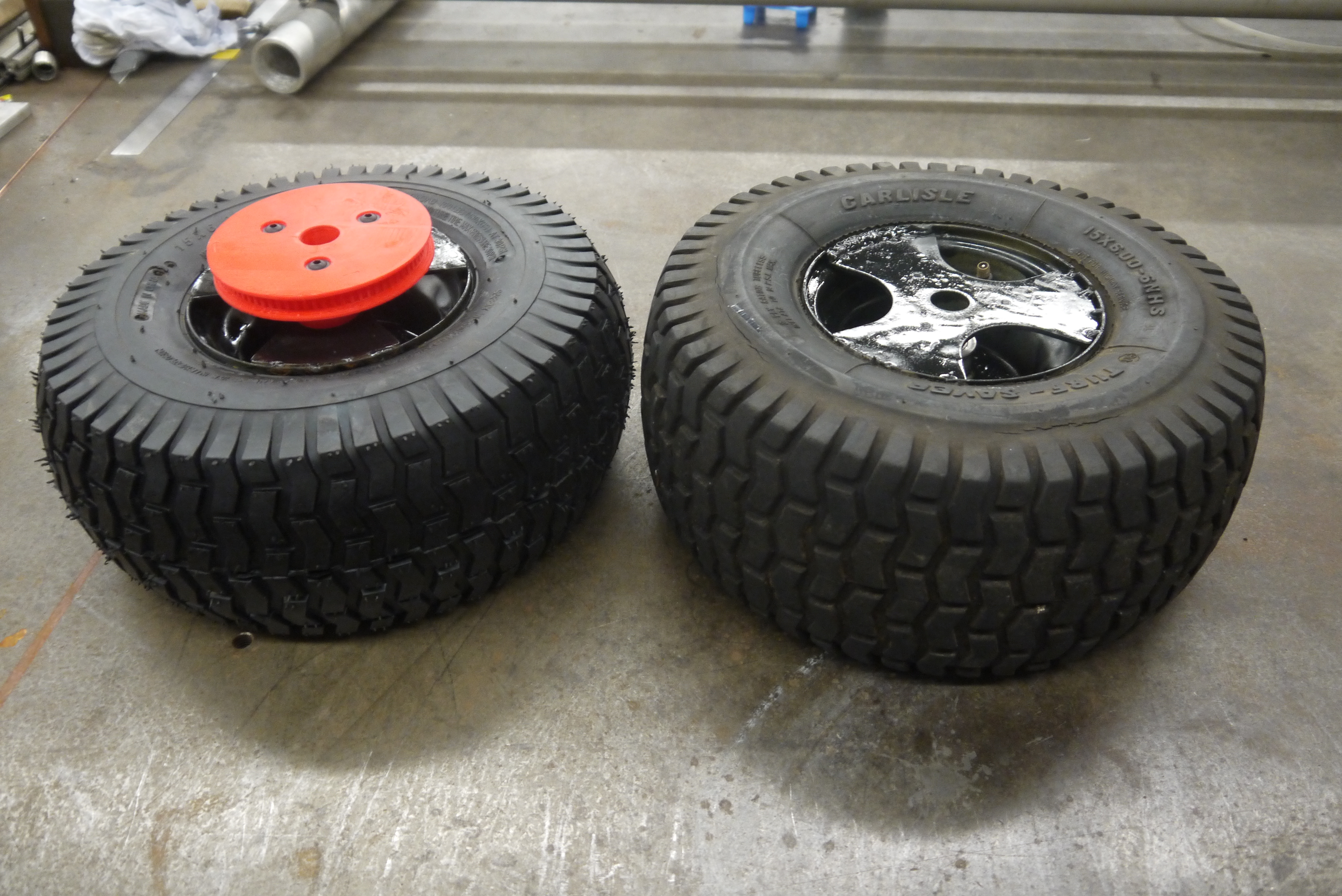
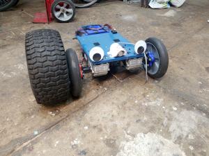
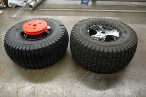
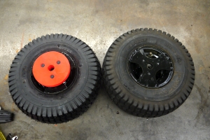
| At
this point i noticed that while both of these tires were the same
'size' the footprint was significantly different. The newer style were
a bit more 'round' while the aged, slightly dried out tires had a more
square footprint. This nominally didnt change things much but it did
result in some double-checking of dimensions. Its a bit visible on the
lower angle shots. |
 |
 |
|
 |
|
|
|
|
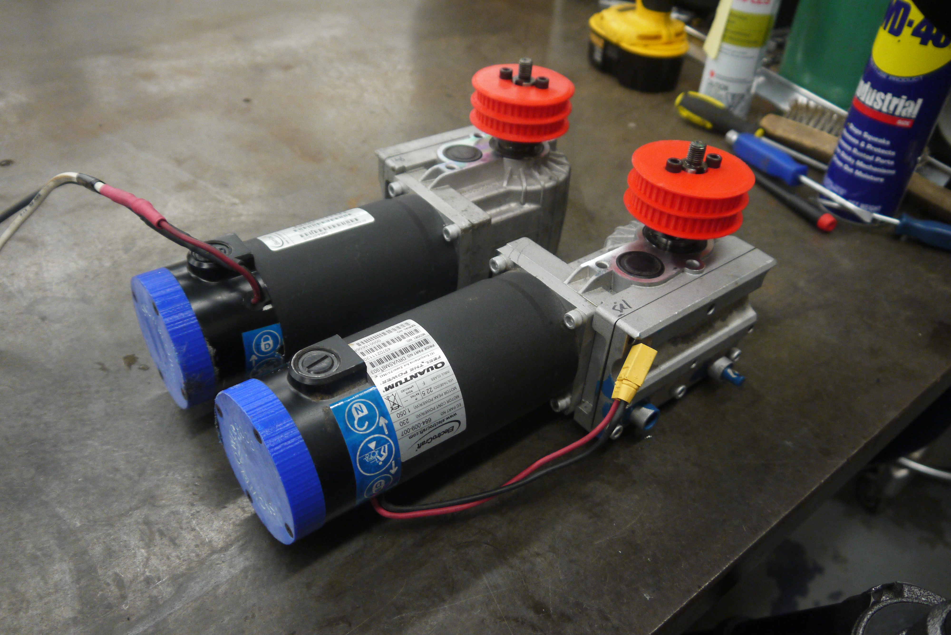
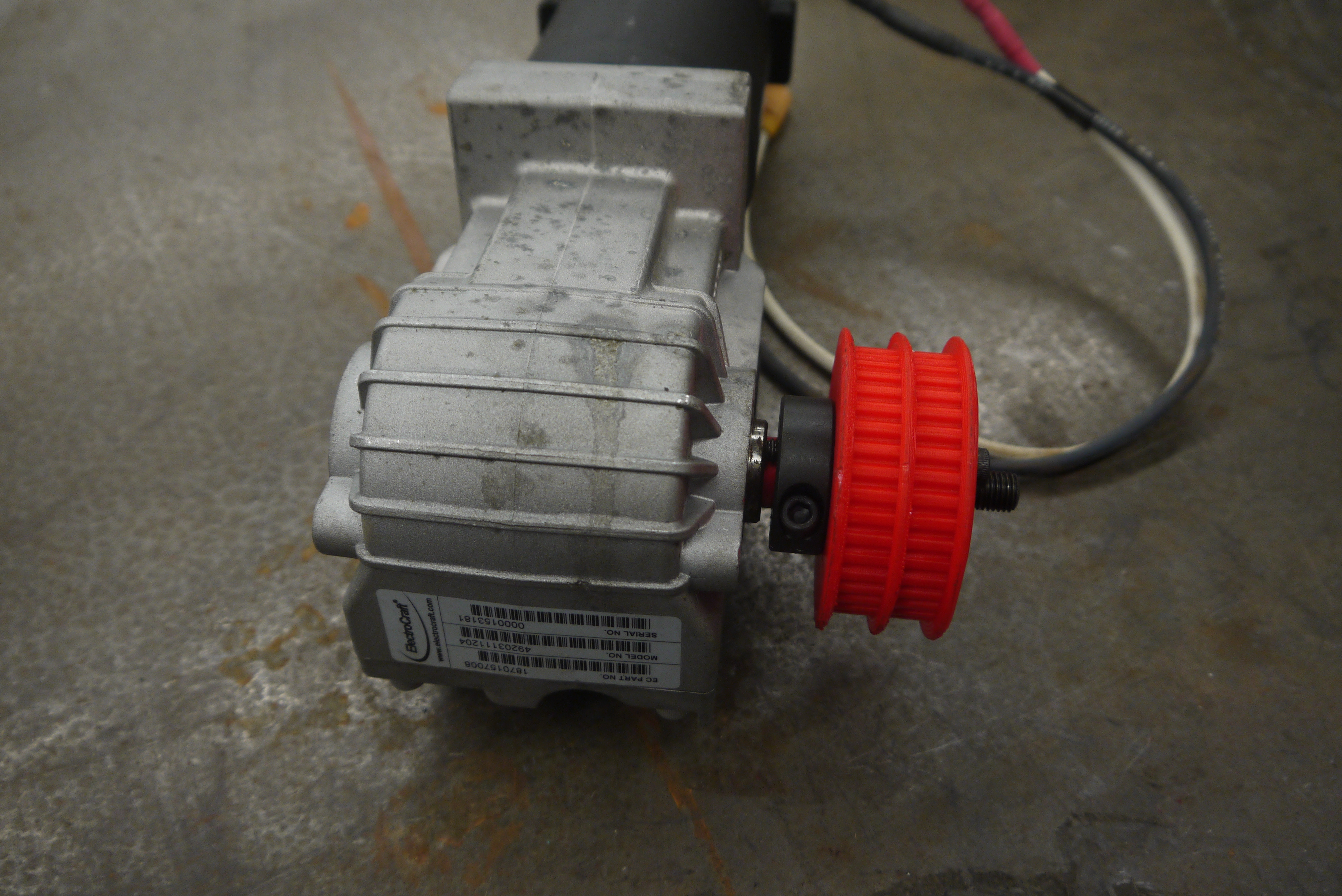
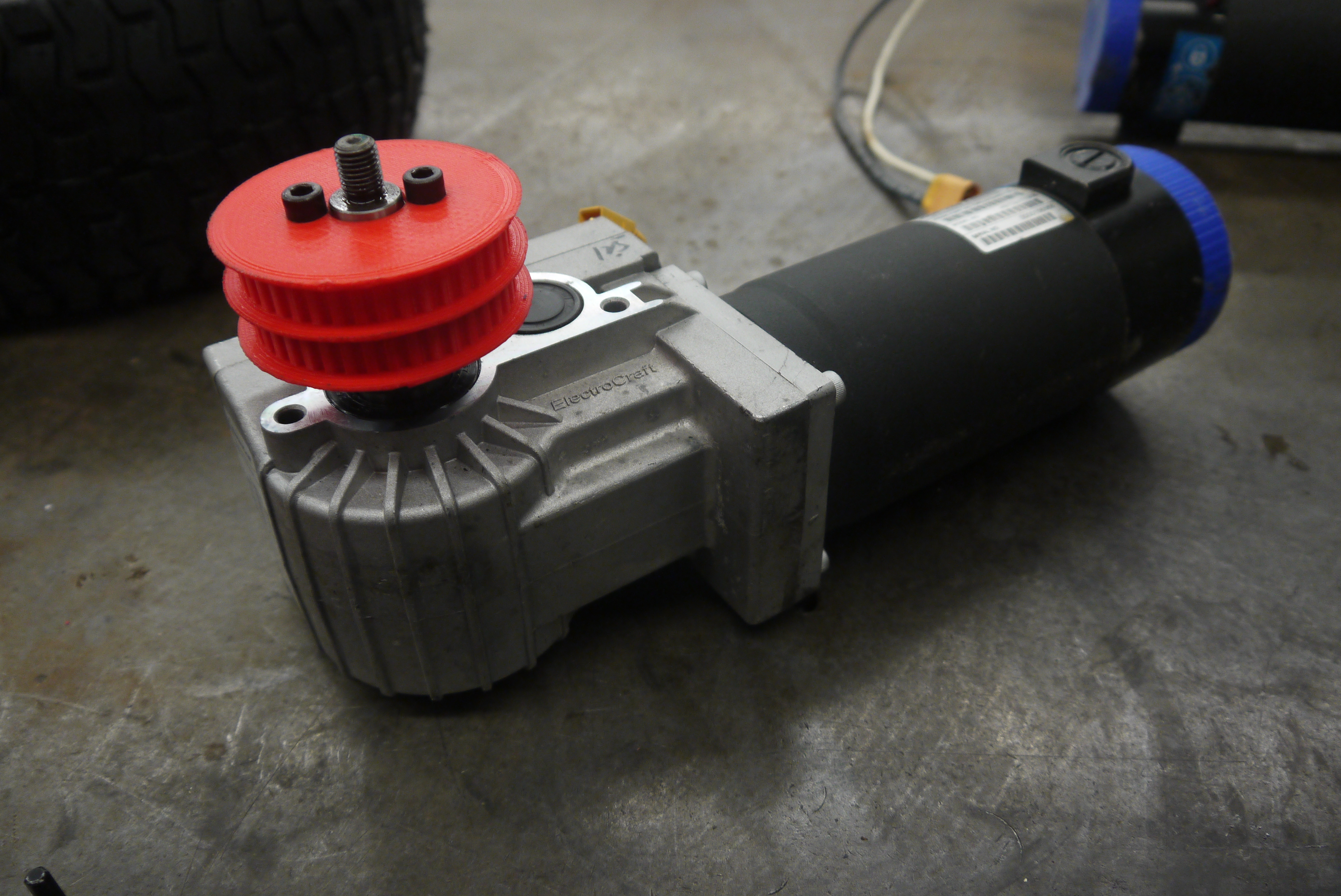
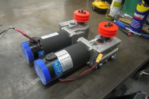
Oh yeah, the wheelchair motor
pulley adapters.
This
was a peculiar one, I want to transfer force to two seperate pulleys,
but also not spend 70$ per pulley on sdp-si. Behold these dorky things.
Its actually a shaft-collar that transfers force to the 3d printed
pulleys via two threaded 1/4-20 socket head cap screws. My logic was
the shaft collar can grab the shaft and then transfer all the force to
the 3d printed pulley. Comically the shaft collar didnt quite tighen
down enough to grab the shaft, so i had to use a shim. |
 |
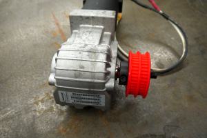 |
| I
wasnt totally happy about a shim being the main thing that was
transfering force from the motor to the wheels, along with the fact
that i wasnt taking advantage of the existing keyway. It was a good
first test part though and wasnt terribly difficult to improve. |
 |
 |