Dane.Kouttron
[12.18.13] Electric Scooter [MK-1]

| What? |
Demo Video | Materials | Layout | The Build | Paint | Battery | Conclusion | Image Directory |
| Initial test-ride video | |
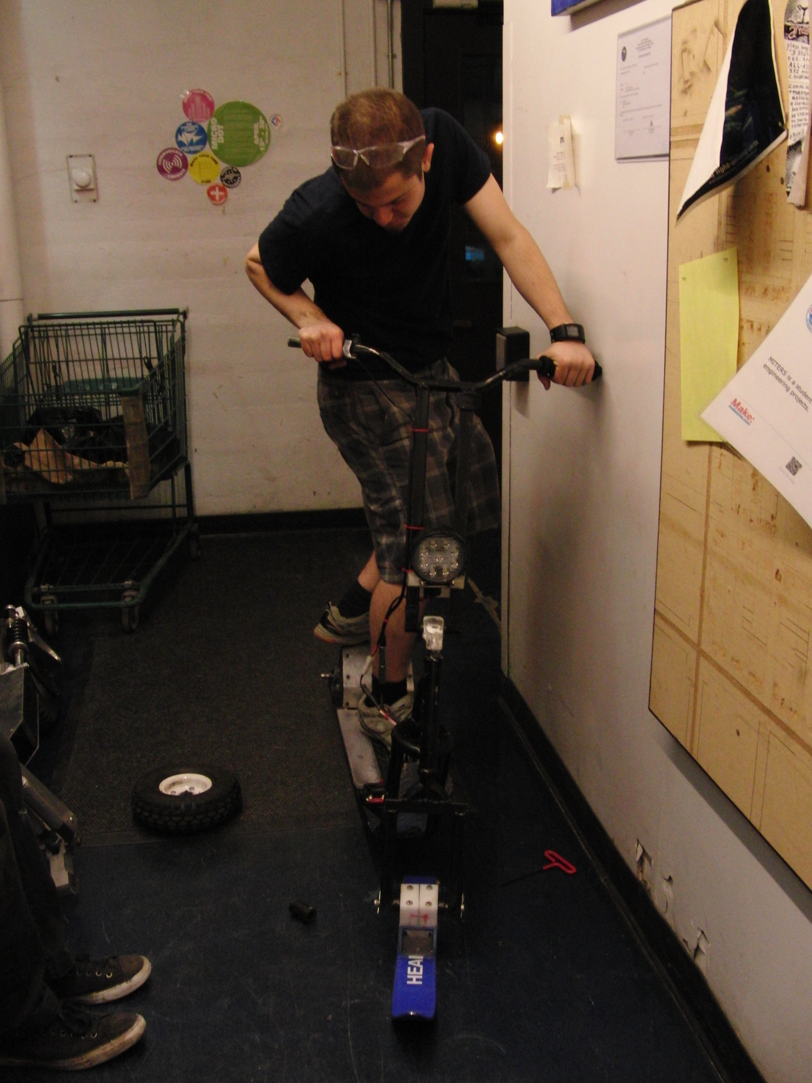
| The following is the absolute
first trial of the Dane-ger scooter mk1. It is powered by a 12S 4P A123 26650 cell module and a ~7kw brushless 3 phase motor. The module is encased in a hardened PET plastic shell. In the initial test video, electronic braking, and indication lighting are not present. Test pilots Charles G, Eric V and Birkel More videos Below |
| EE layout | |
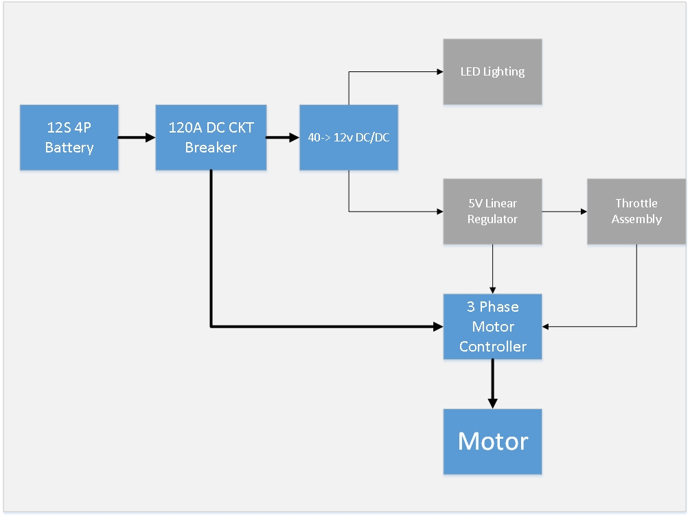
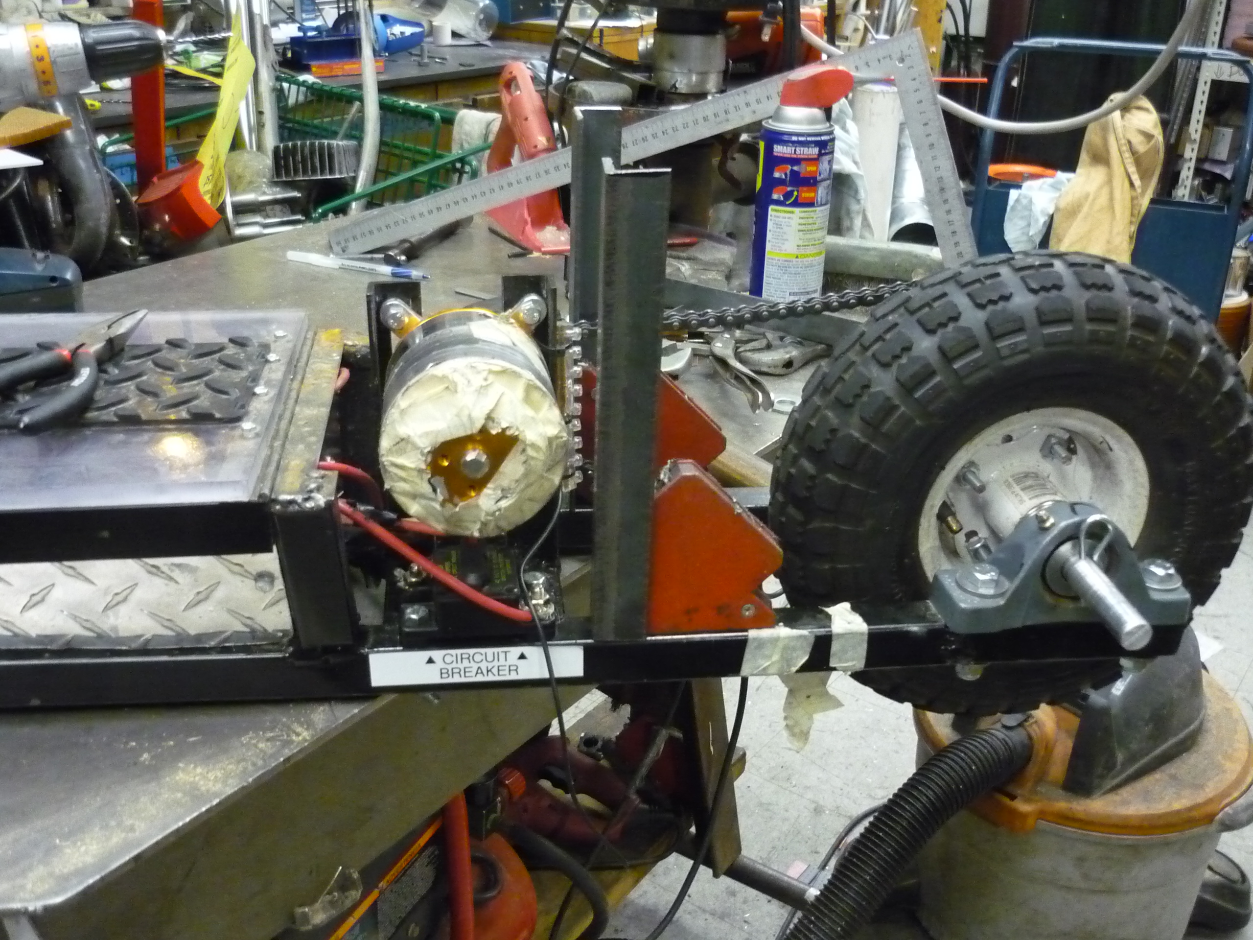
| The
electrical layout for the MK 1
scooter is fairly straightforward. Everything starts from the 12S 4p
cylindrical battery module [documented
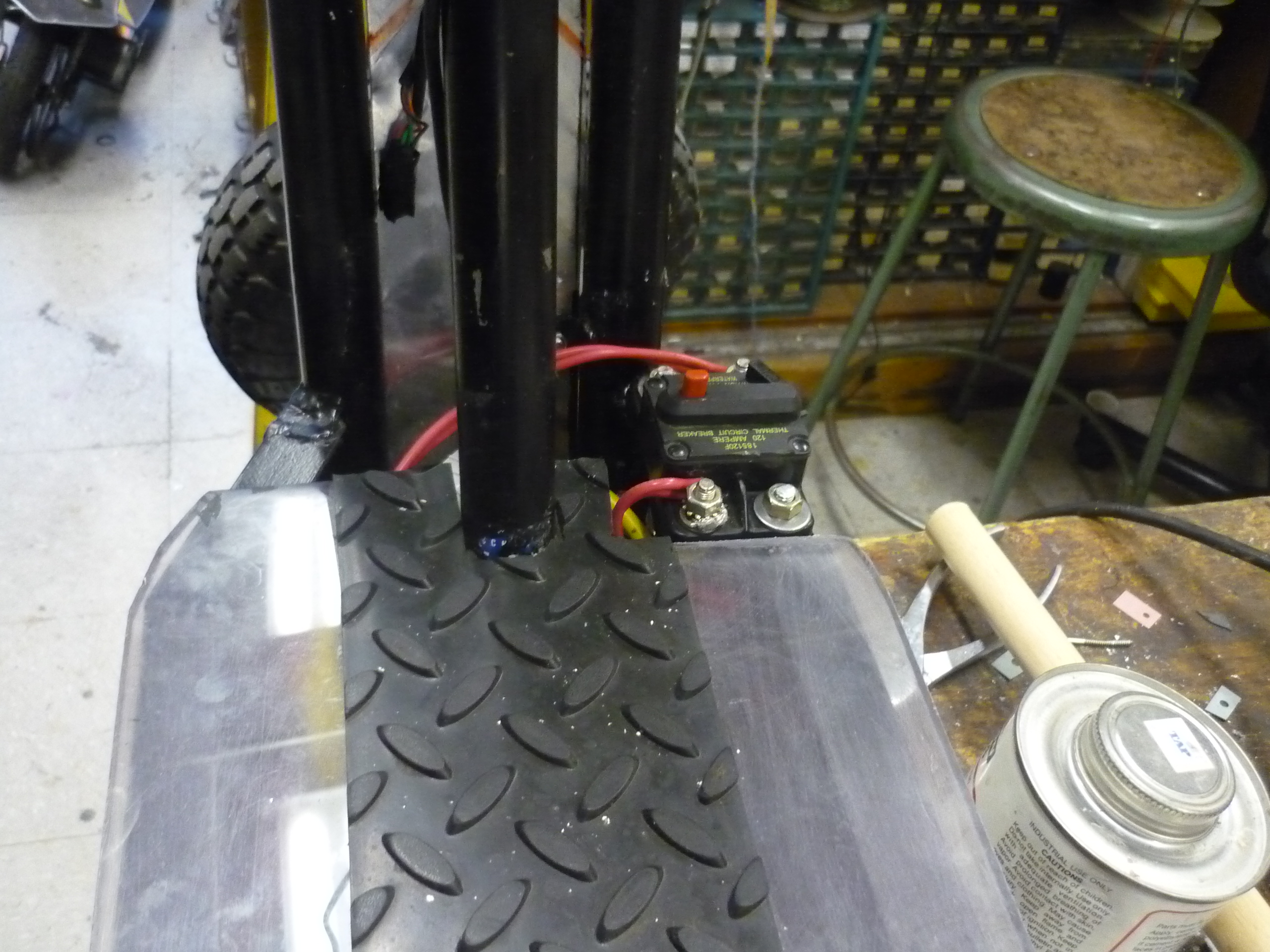
below]. A Cooper Bussman 120A circuit
breaker sits between the battery and the rest of the scooter. Note
that, while there are a number of DC circuit breakers out there, VERY
few actually tolerate vibrations. I found this out the hard way when I
started using [link]. The first hint of vibration
and the breaker
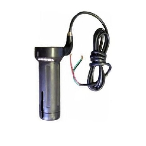
tripped, which, made it fairly hard to use. The headlight I chose is a
fairly awesome 30W led setup with a 30 degree beam path. It has an
onboard dc/dc, but unfortunately its max input voltage is 30V. I used a
40W dc/dc to bring the module voltage back down to 12v DC, which is
useful for driving the LED assembly as well as 12v accessories (if I
opt for adding a sealed 12v cigarette lighter outlet). Finally a linear
regulator feeds the 5v logic for the three phase sensorless controller
and
throttle assembly. Having a wiring layout and connectorizing things is fairly helpful, especially as this is all crammed into a fairly small space. |
 |
| Cruft
and mig welding, |
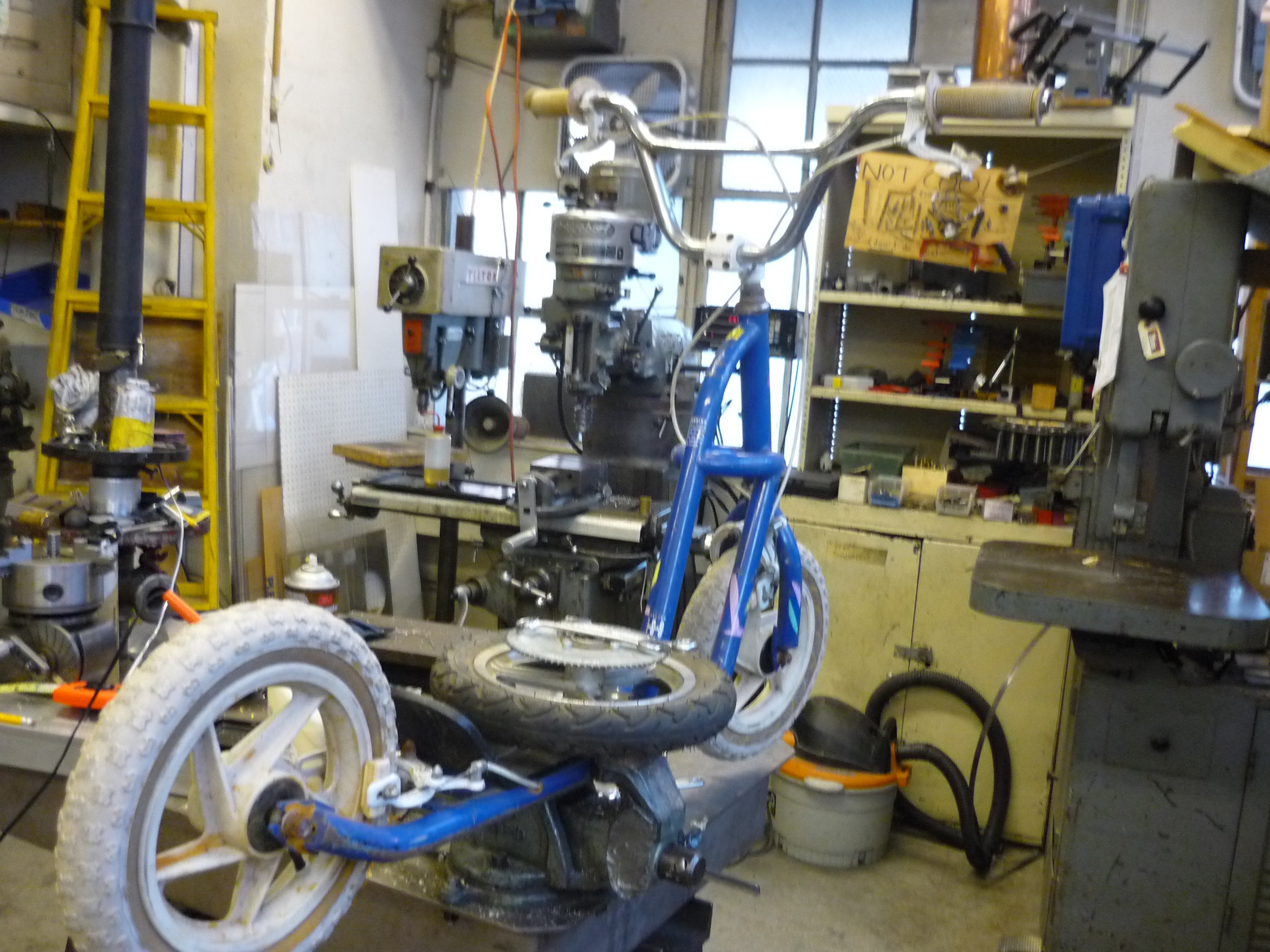
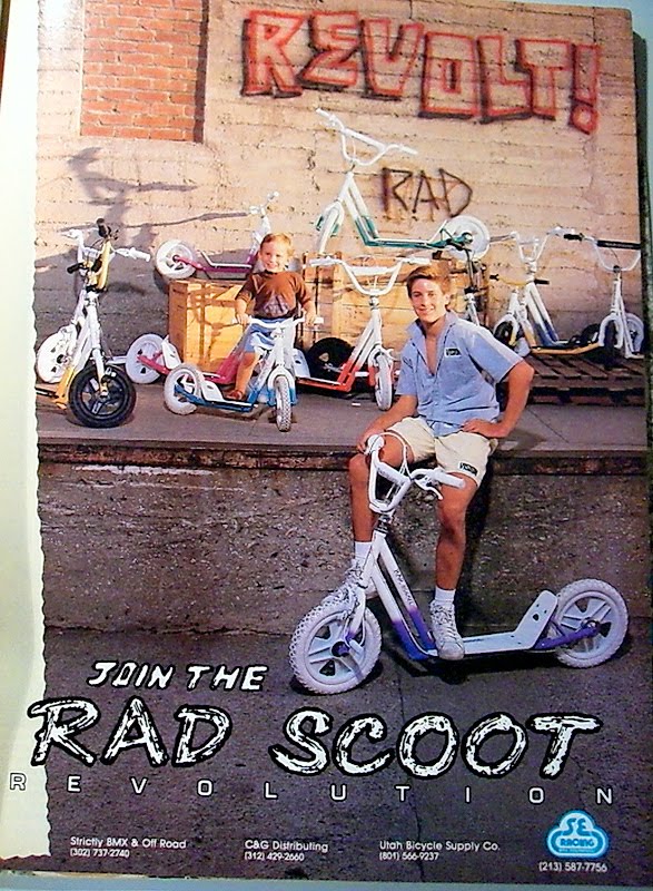
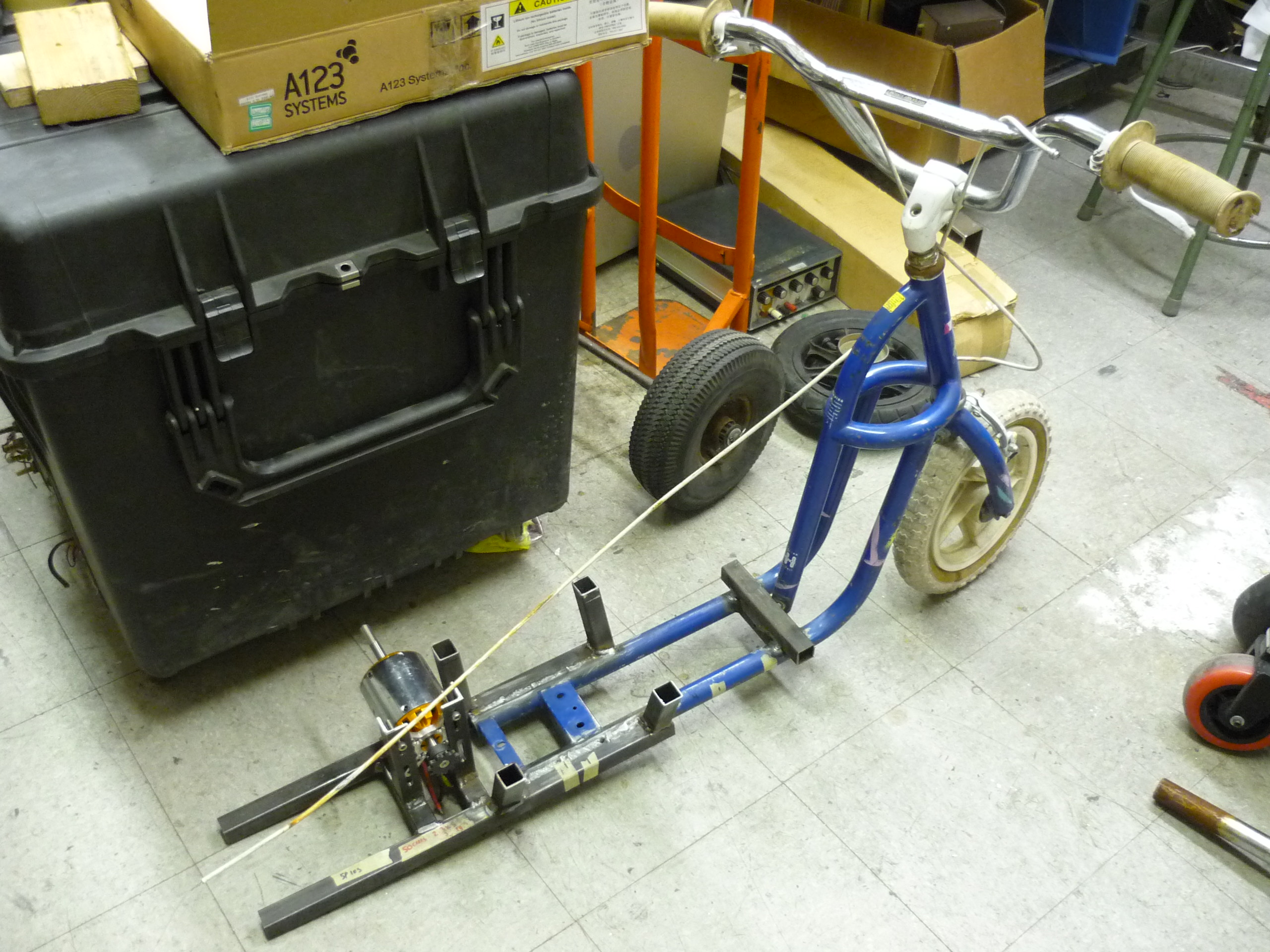
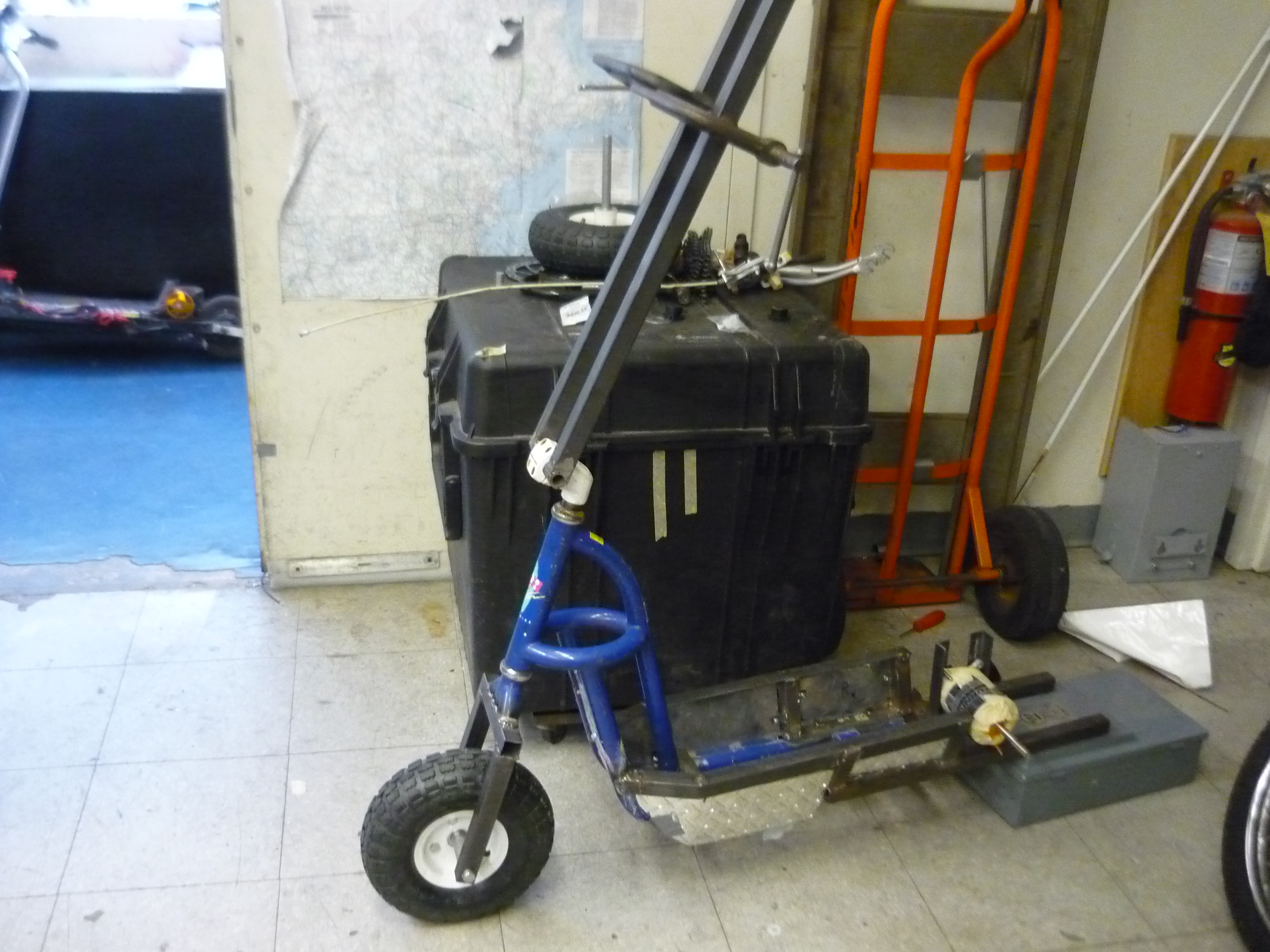
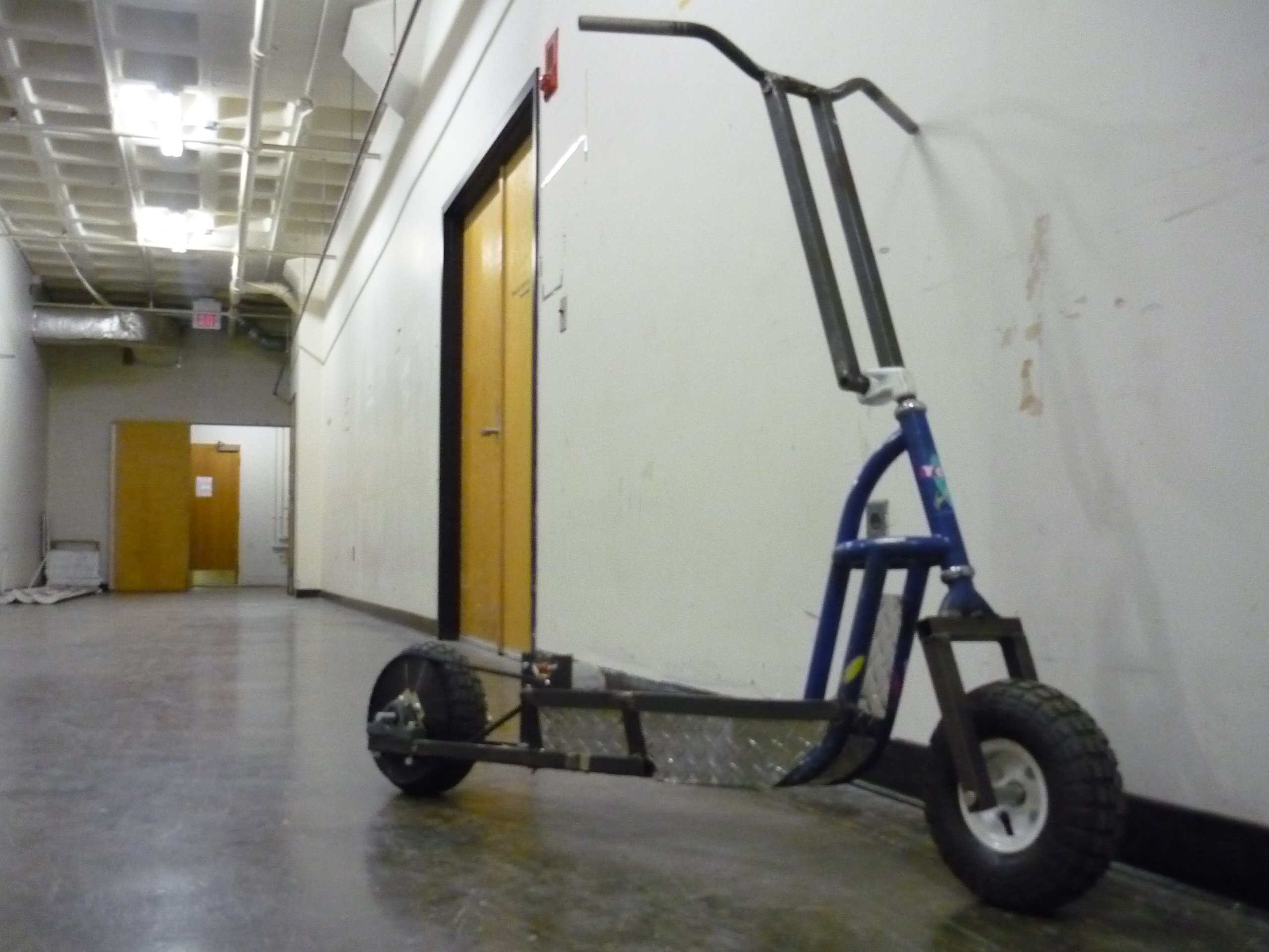
| Old 80's push scooter The base for this project started from a craigslist posting for an 80's push-scooter, I was able to purchase this for 10$, in 2011. It uses small white 14" tires and has a cantilever brake system. Note, if this scooter frame looks familiar you've probably seen macklemore's thrift shop video [pic] [vid] Its the same frame. So effectively this is a macklemore approved project. |
 |
 |
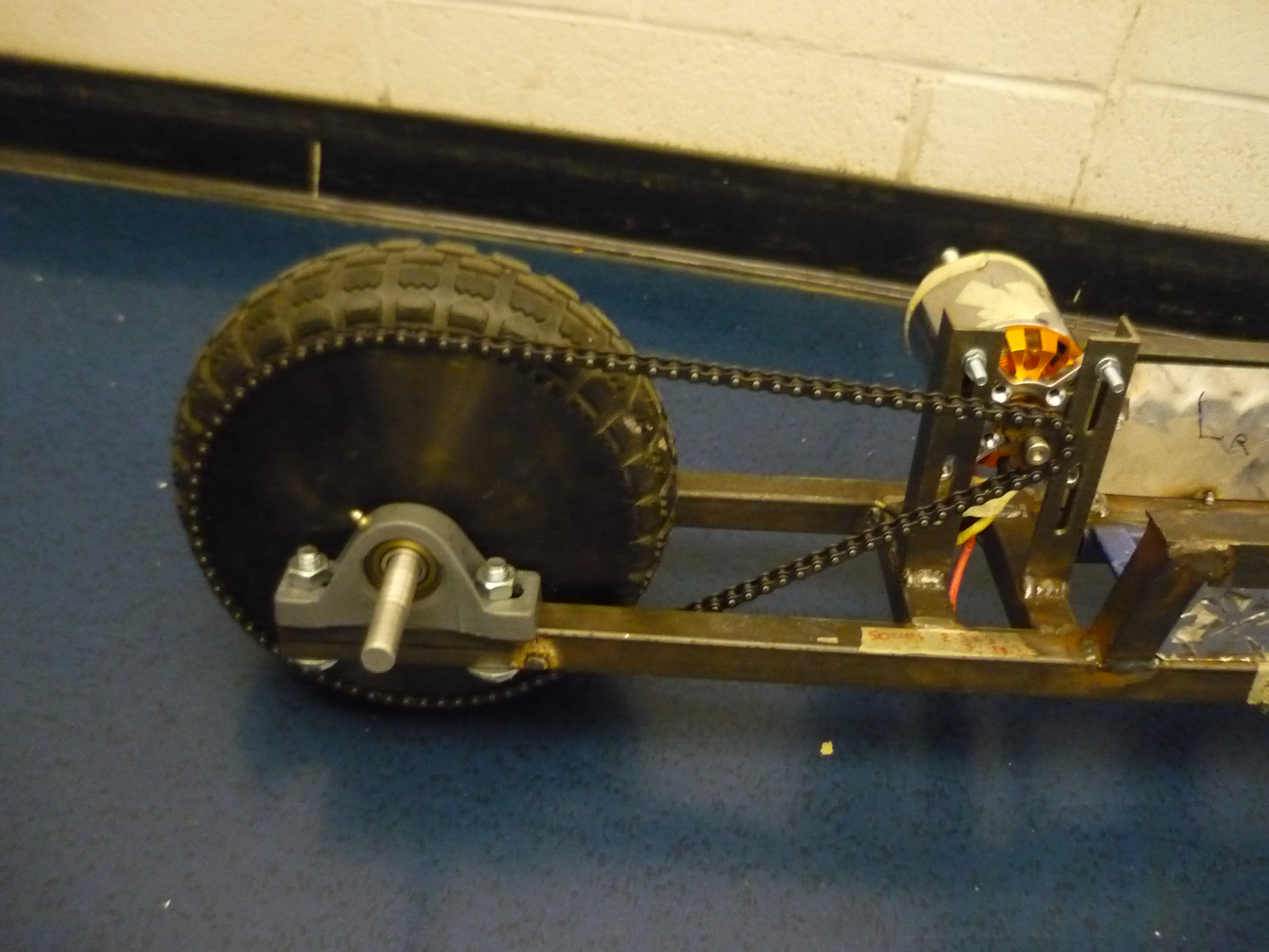
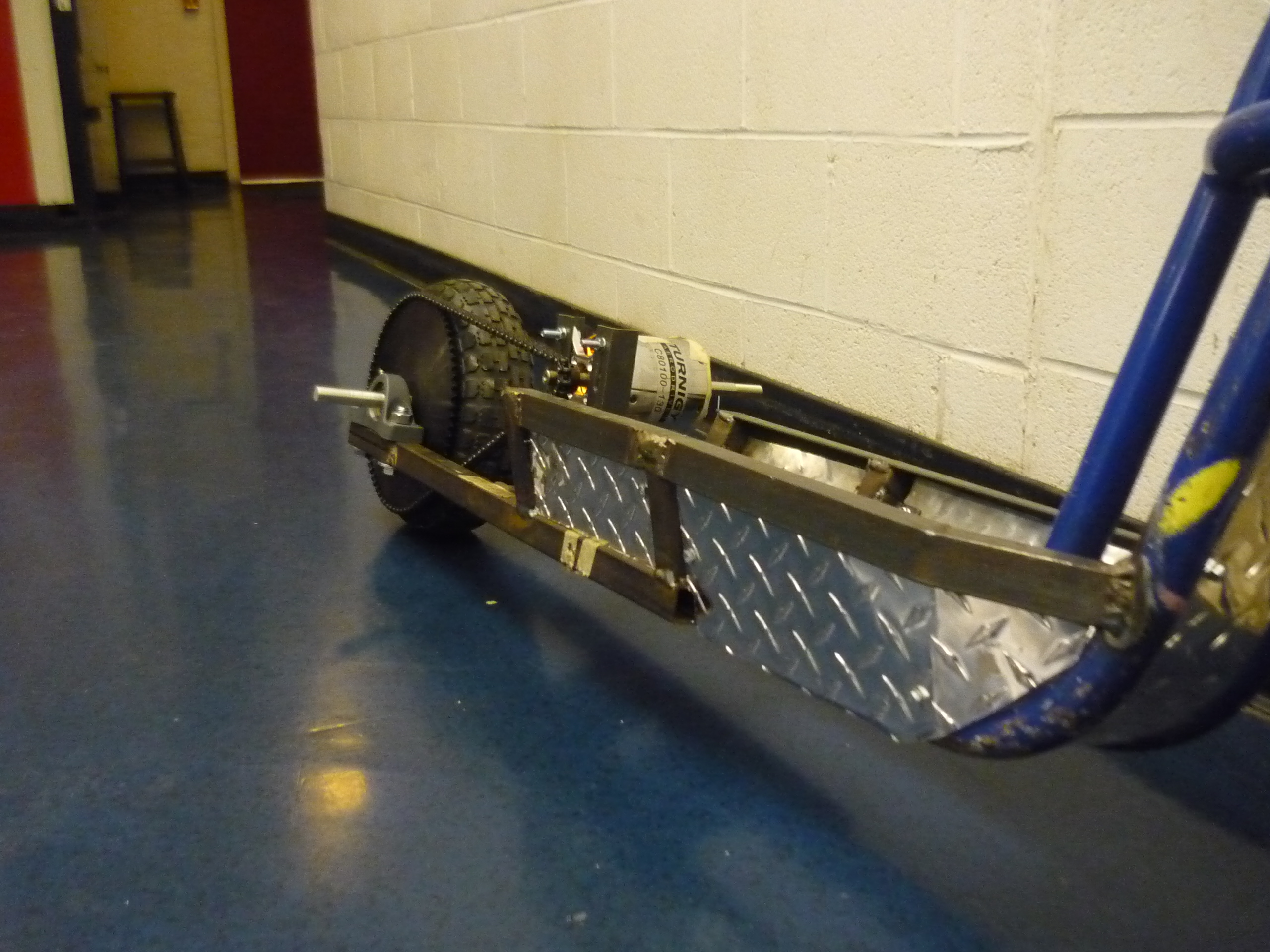
| Motor The motor for this project is a hobbyking 80mm 180kv/rpm three-phase, brushless motorand can bequeath ~7kw peak, in the right conditions. A similar motor can be found at Leader Hobby, or from Charles G [Link] |
 |
 |
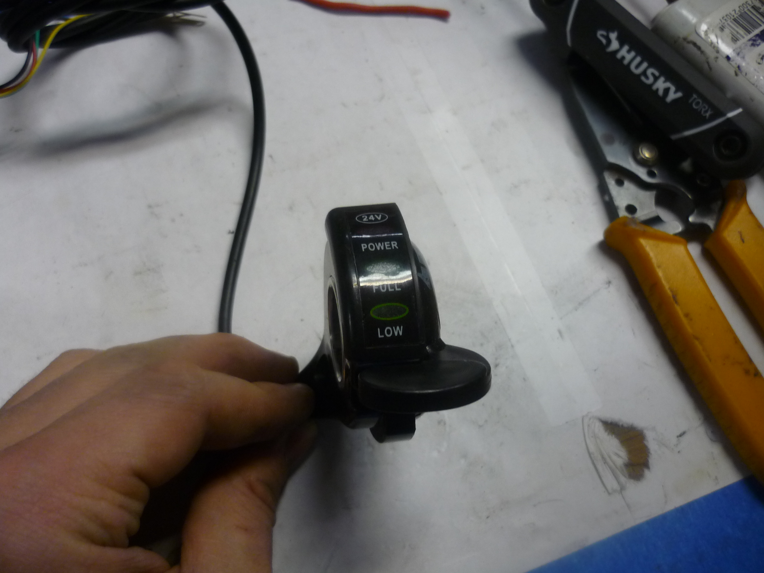
| Throttle Assembly The throttle assembly was purchased off of amazon (link). For the price, it's a decent assembly. It fit the bicycle-scooter handlebars perfectly. Eventually I switched to a thumb-lever type throttle, as its less prone to accelerate wildly as you fall off the scooter, gripping the assembly and twisting it to accelerate more... It does have a fairly touchy response curve. Note that I did not wire in the voltage sense led indicator, as it would have little to no effect, due to the SOC vs Voltage for iron-phosphate chemistries. |
 |
 |
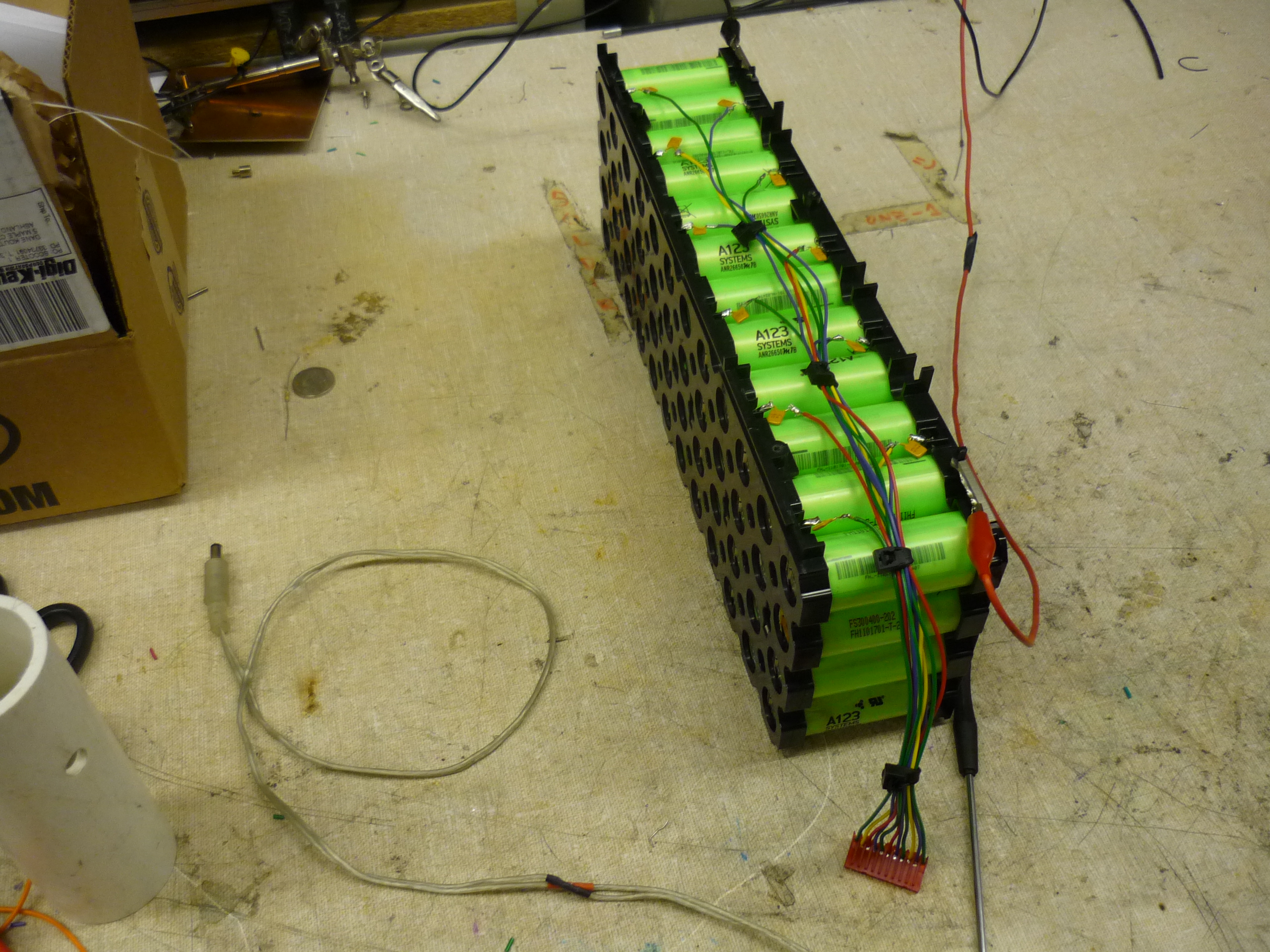
| Battery I was able to acquire a 12S 4P A123 26650 M1B battery module (sans pcb), headed for the scrap-heap, while I worked at A123. Its a phenomenal module, and sources an unbelievable amount of current. At 10Ah, and 40V it has quite a bit of capacity, enough for an~ 8 mile range. Note that each cell group is wired to an external MTA100-series connector. Each voltage / balancing line has a 1A PTC in-series to prevent the condition of balance leads shorting against each other in the case of an issue. |
 |
 |
| Motor Controller Initially I started with the Hobbyking 120A ESC [similar], and slowly developed a homegrown variant [link]. The hobbyking controller has its advantages and disadvantages. Its incredibly small and fits well in the packed scooter 'hull'. The controller has no current-control, 25% throttle equates to 'use a semi-infinite amount of amps as possible to achieve 25% motor speed. On a vehicle platform, a lack of current control feedback results in more of a 'velocity control' not 'acceleration control' which can be unwieldy. |
 |
 |
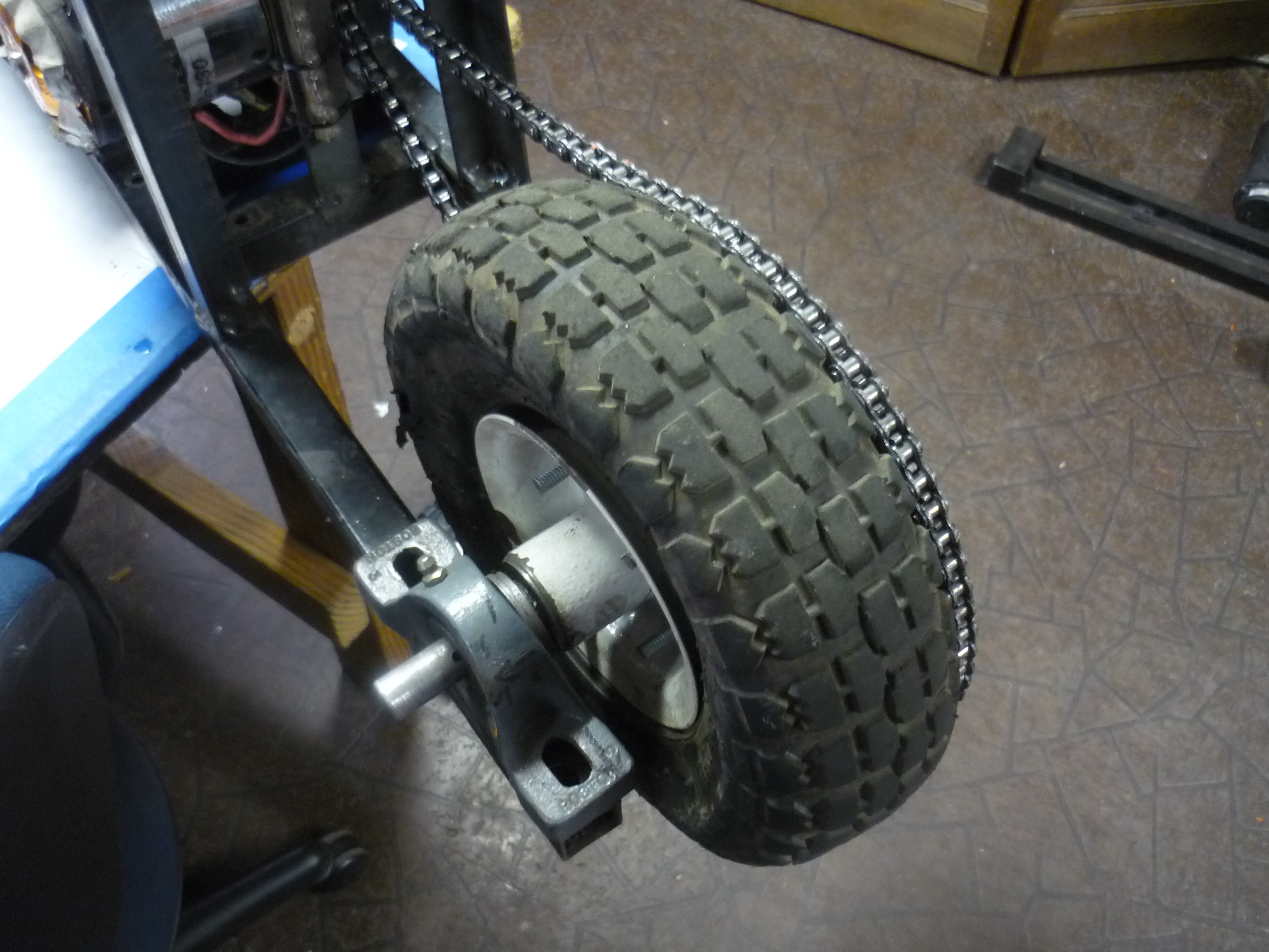
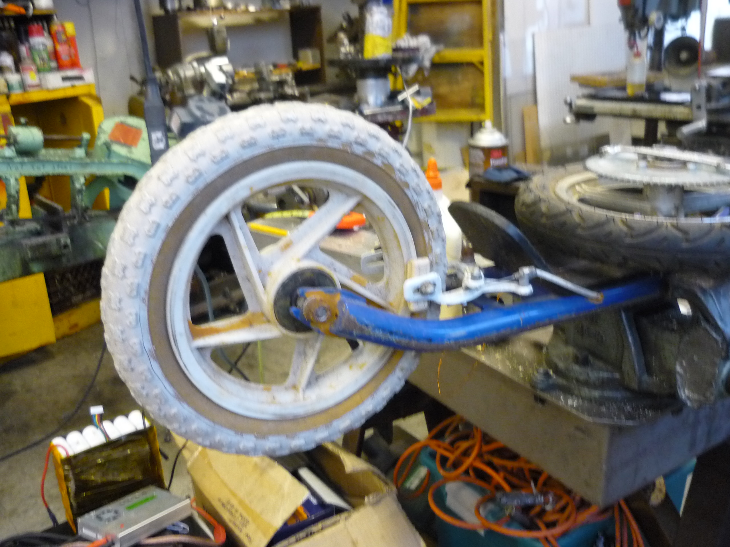
| Wheels I went for cheap, easy to replace tires from Harbor Freight [link]. At ~7$ each, I couldnt beat it. As a note, the tires aren't rated for greater than 20mph, but that's kindly ignored in this project. The wheel, when properly inflated, is roughly 2" in diameter larger than the rear sprocket. |
 |
 |
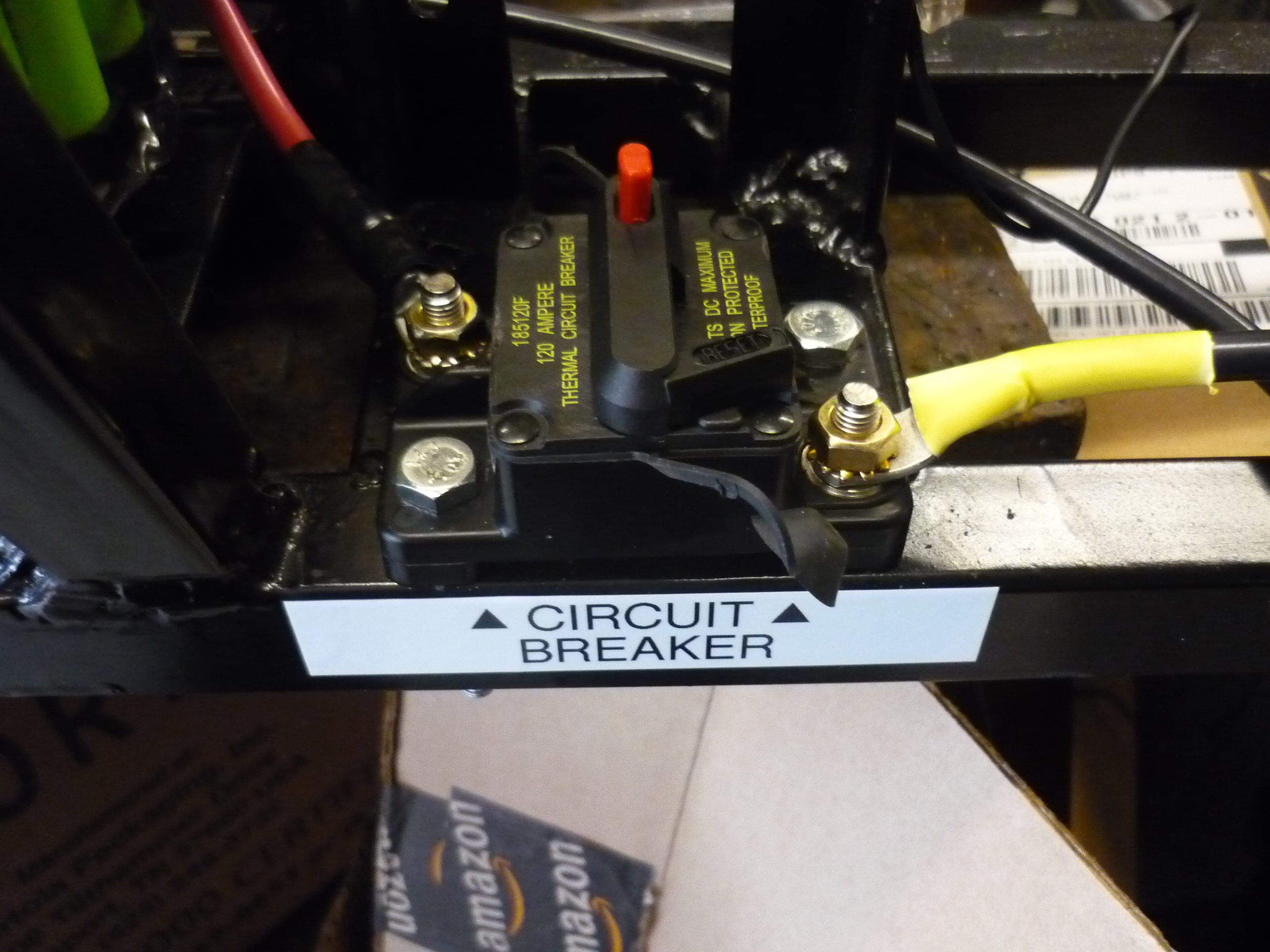
| Circuit Breaker Here's a neat part: Its common to First Robotics, and probably for good reason. Its a vibration resistant 80A DC circuit breaker. I specifically noted 'vibration resistant' as the first part I tried [link] would trip whenever the scooter went over a significant bump. |
 |
 |
| Brake Assembly The MK1 electric scooter lacked mechanical brakes and relied on electronic breaking, as space for mechanical brakes was not allocated during the initial build phase. The emf-brake consists of a 3 pole relay, connecting each of the 3 phases together in a delta configuration through 0.5 ohm pulse power resistors. This decelerates to a usable speed within a few hundred mili-seconds. |
||
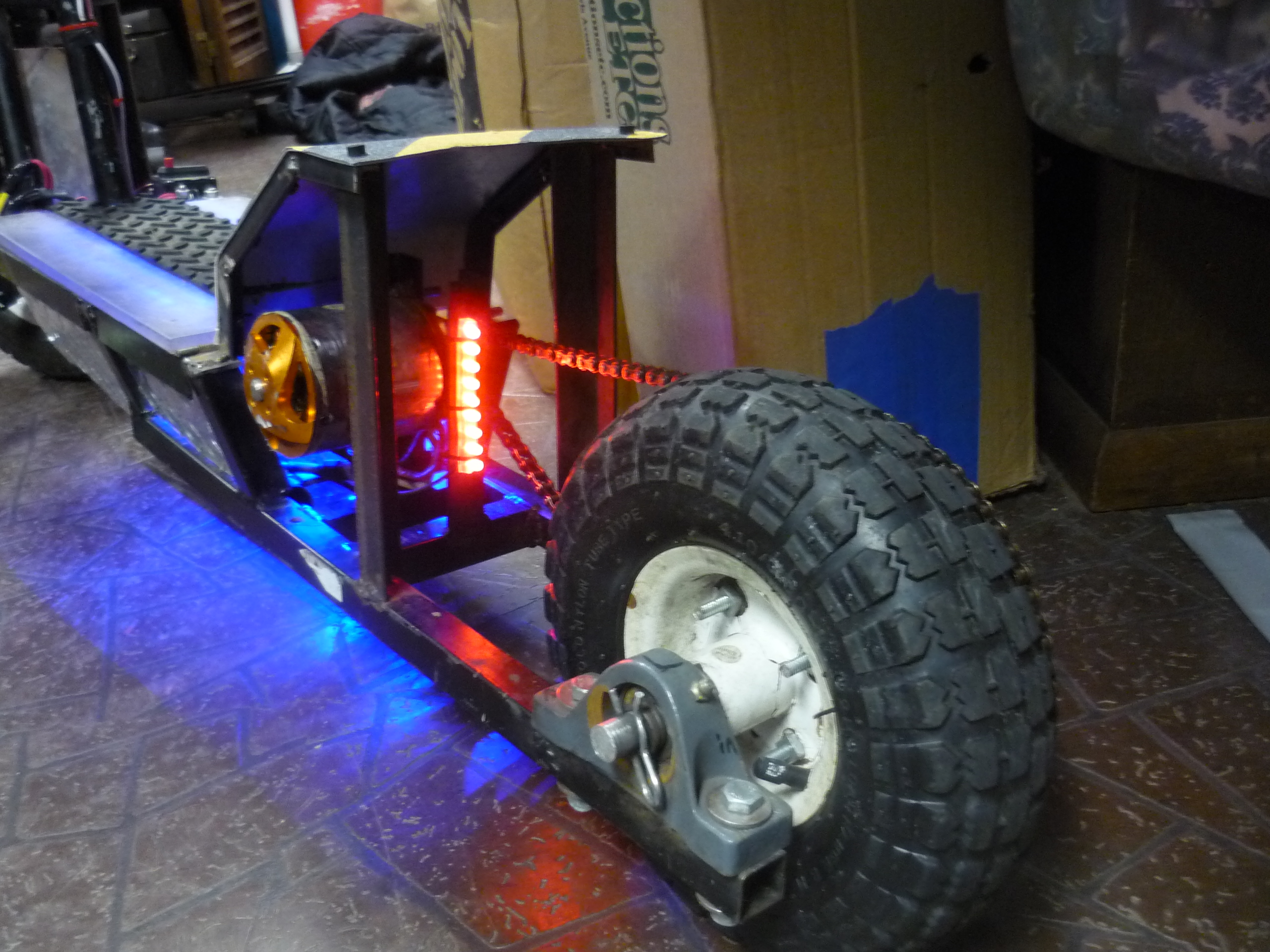
| Rear Lights For the rear lights I used a 12v led strip (9 leds) from amazon [link]. At the moment it is tied directly to the 12v dc/dc converter output and is 'always on' it can be tied directly to the 'EMF brake' however I may add another led strip for indicating the EMF brake is applied (similar to the rear running lights used in automobiles) |
 |
 |
| Head Light Assembly I purchased this led light assembly [link] for 18$ and so far it's fantastic. So much so, I had reccomended its use on a sibling's contraption [link] I used an older MIDI extension cord as a quick-disconnect cable to power the lamp + throttle assembly. The light is actuated by a series IP65 rated switch hidden behind the light. Its mounted on a pivot which allows for re-positioning if it drifts up too high. It's incredibly bright, as shown in the snow-scooter video below. |
 |
 |
THE BUILD
| What |
||
| Beginnings This project was born from a rather silly kick-scooter from the 80's. As far as I can tell, it was called the 'Rad Scoot'. I aquired this bohemoth from craigslist for a whopping 10 dollars. It had the stock wheels and brakes, both dry rotted and semi-rusty, and in dear need of hudspeth. The weelbase is fairly short and the handlebar height is geared towards a 10 yr old, but the construction is intense, bicycle-grade steel tubing and bicycle-sized bearings for the steering linkage. In comparison to the 100$ fancy razor scooters, this is a steel-tank. The handlebar mechanism is not foldable, but can be removed via the allen-key tension linkage inside the steering column. |
|
 |
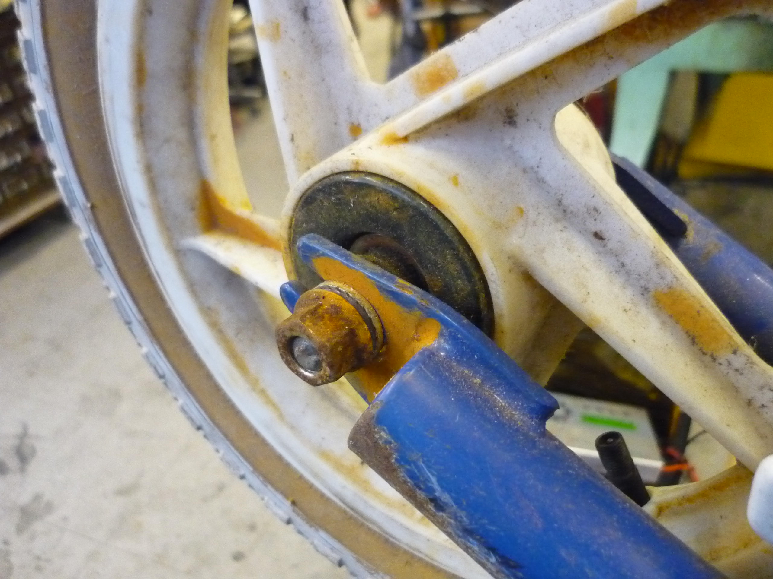
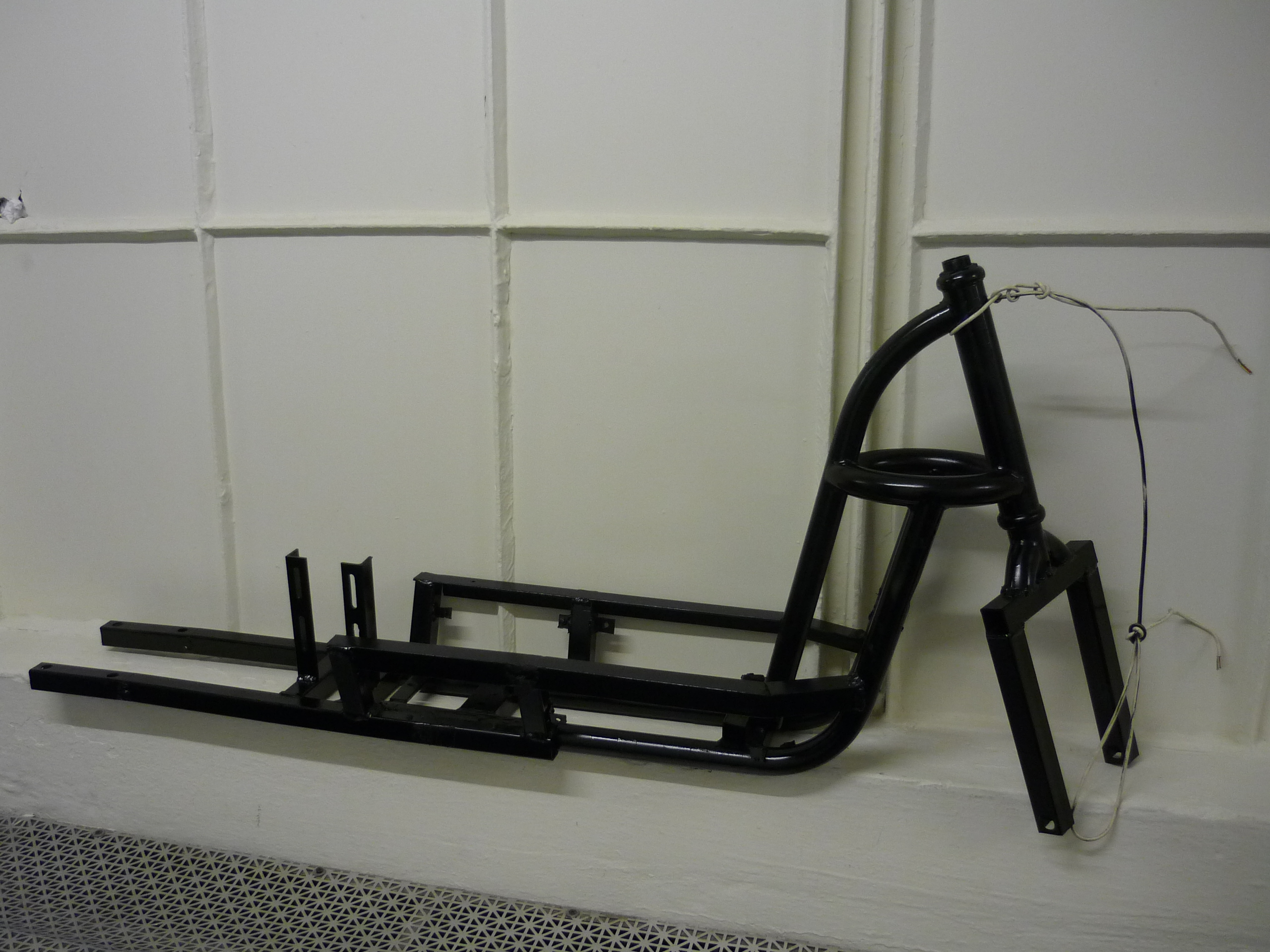
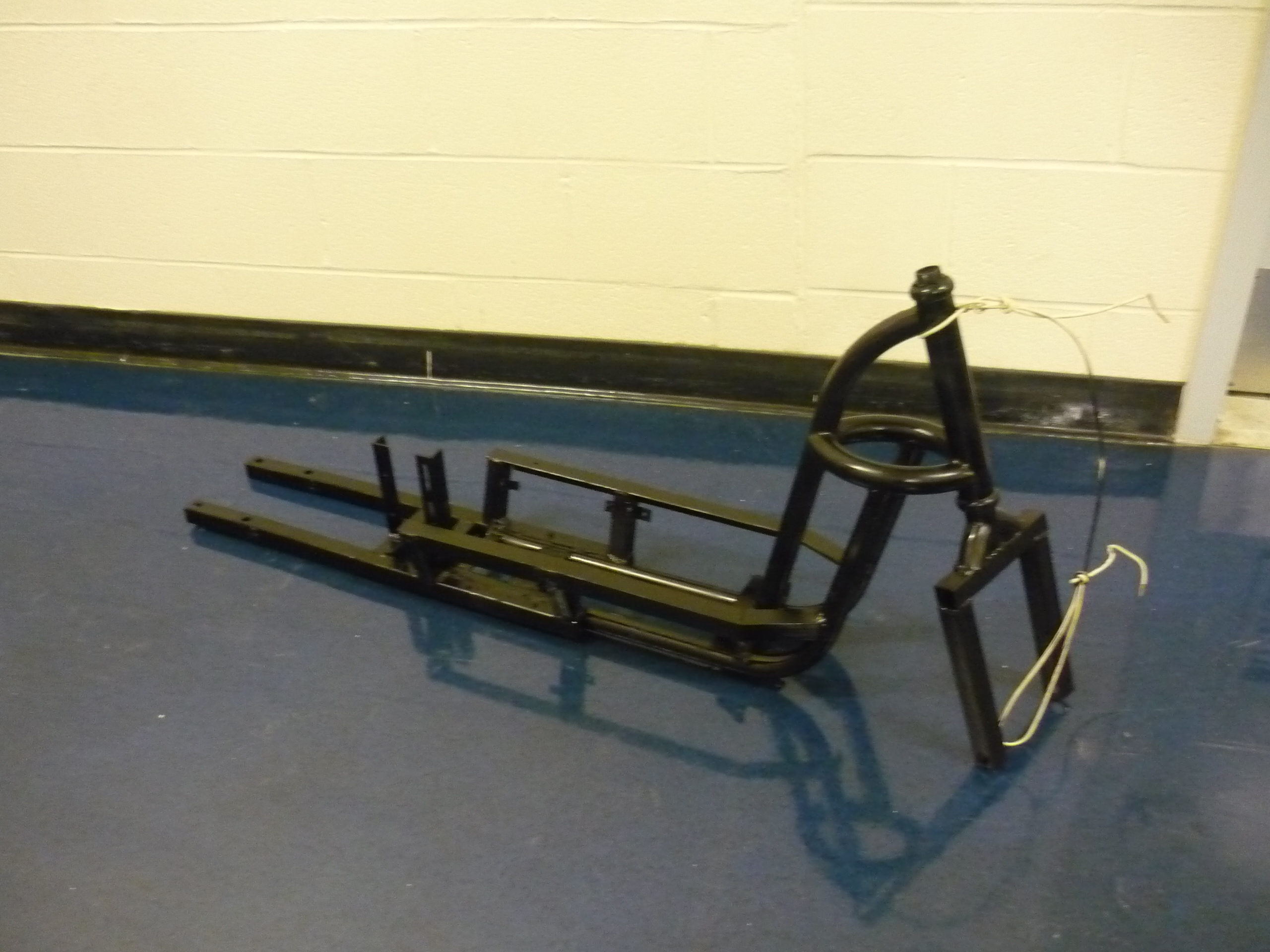
| The Frame The stock scooter was very short, and the rear-end seemed to suffer from the most rust on the craft. As i needed extra space on the rear of the scooter, i removed the wheel + brake assembly. The brake had probably dry-rotted 10 yrs prior and its adjoining linkage was equivalently uv-damaged. |
 |
 |
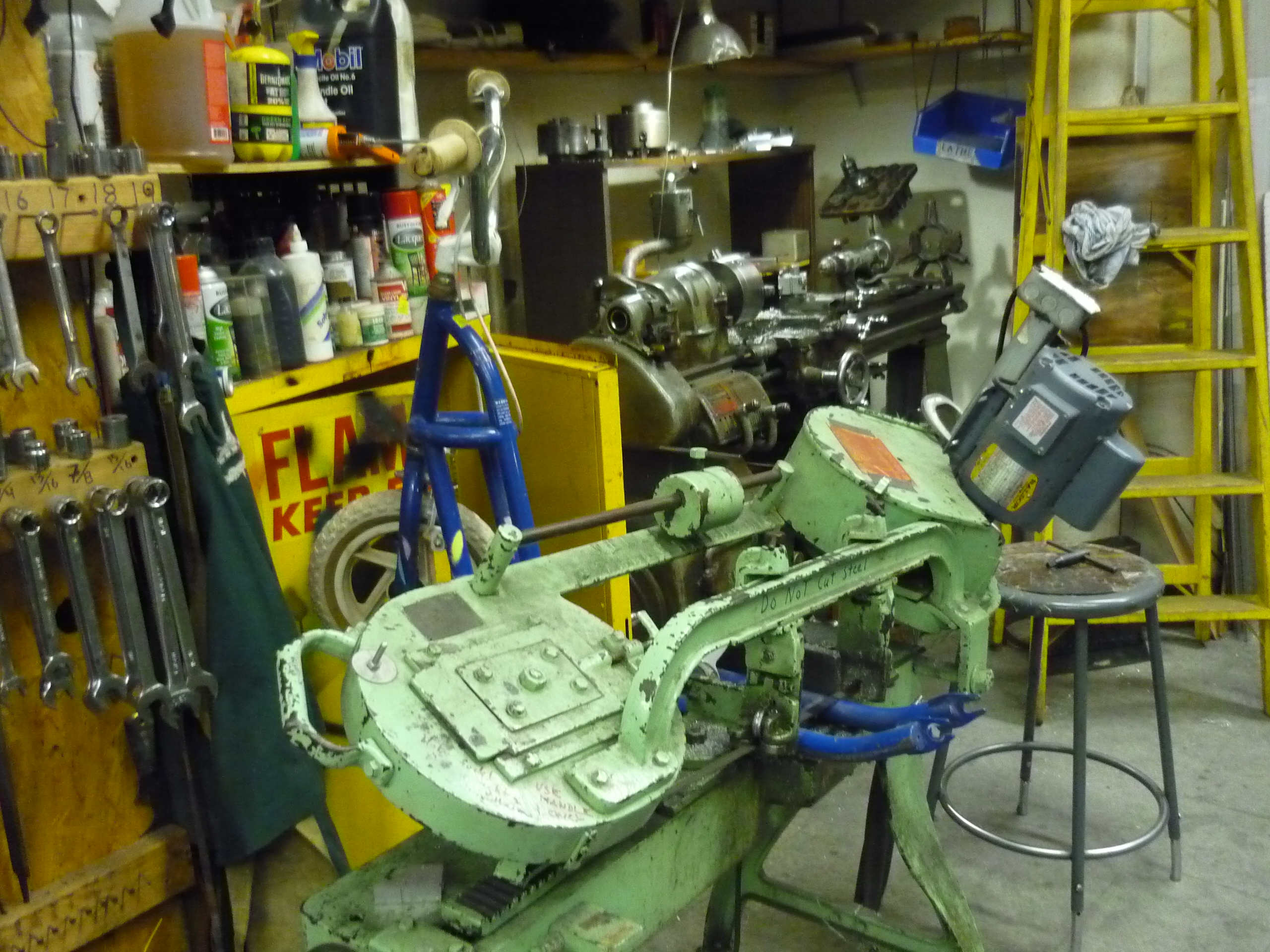
| Chop
Chop The horizontal bandsaw made quick work of making a semi-even cut through the back half of the frame. I could tell the saw was oddly happy cutting a scooter in half, which was slightly discerning. |
 |
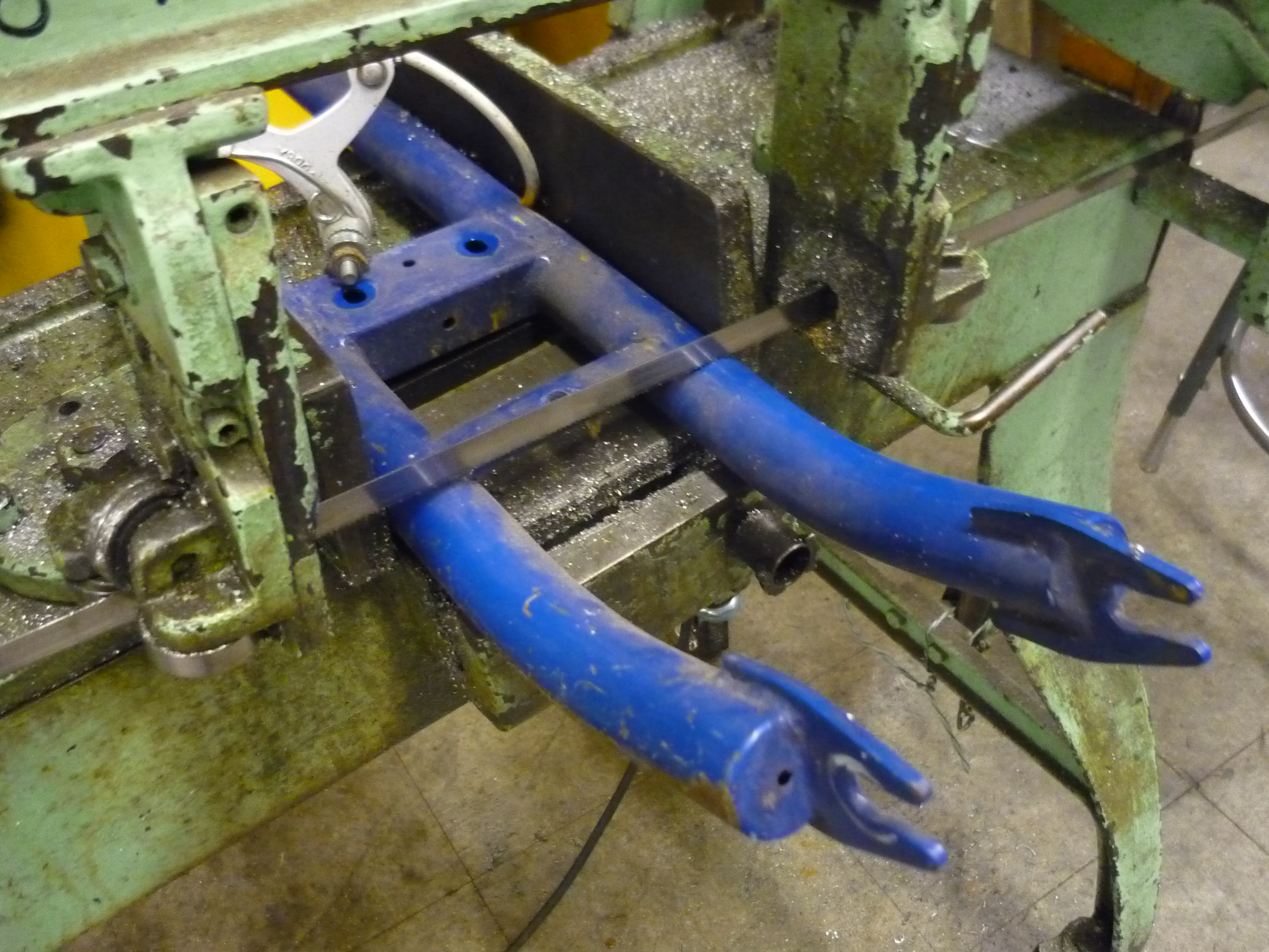 |
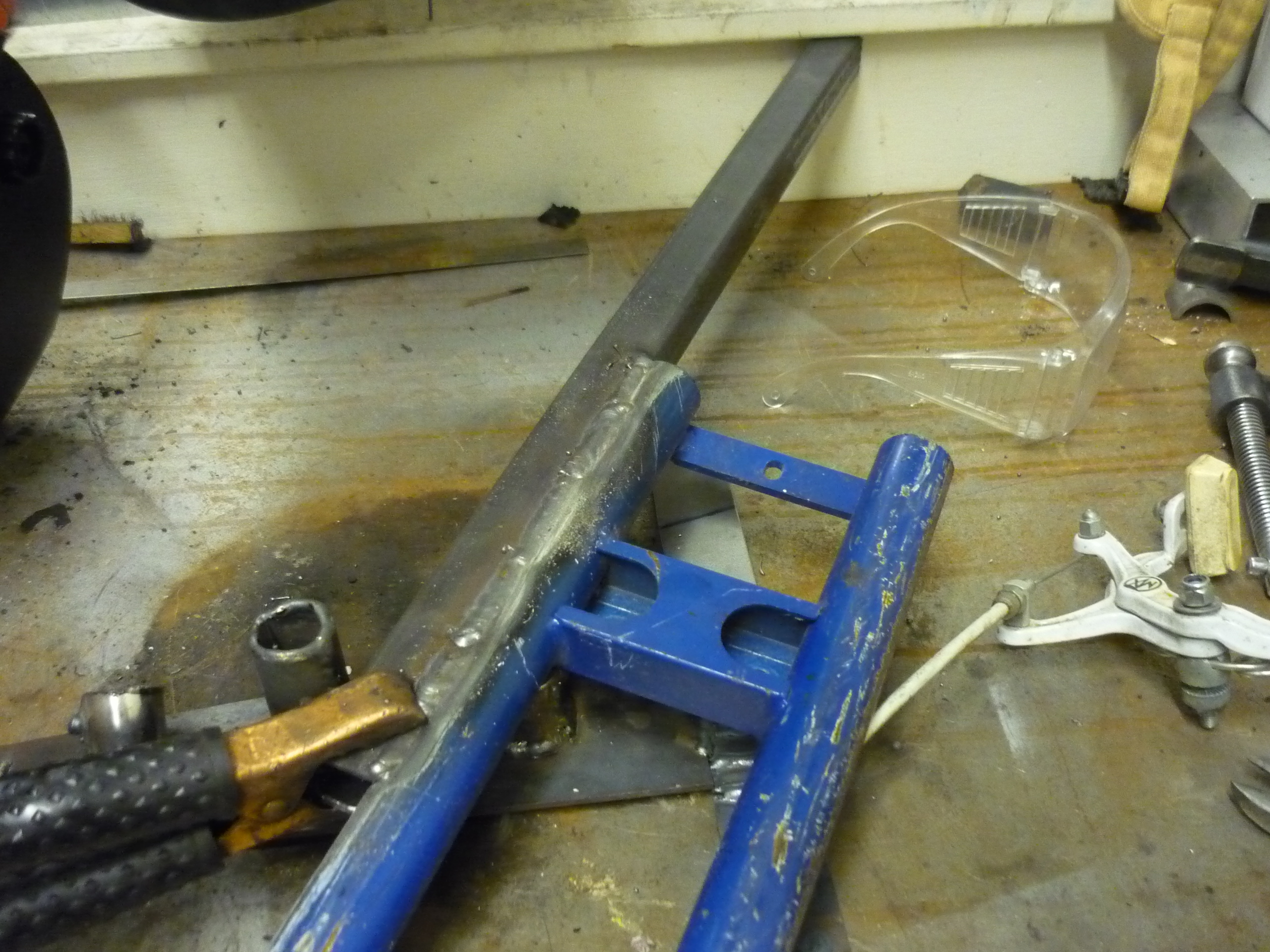
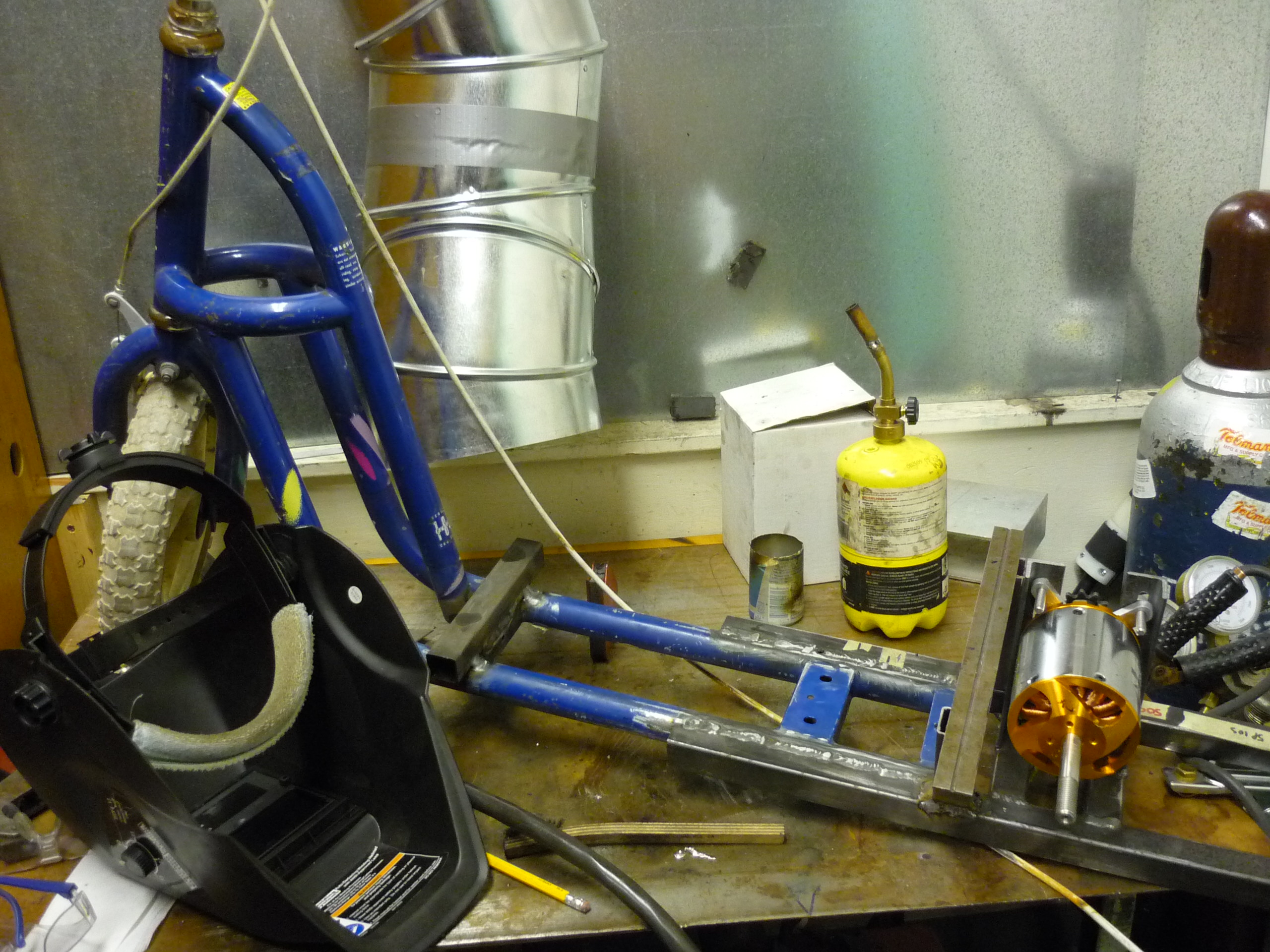
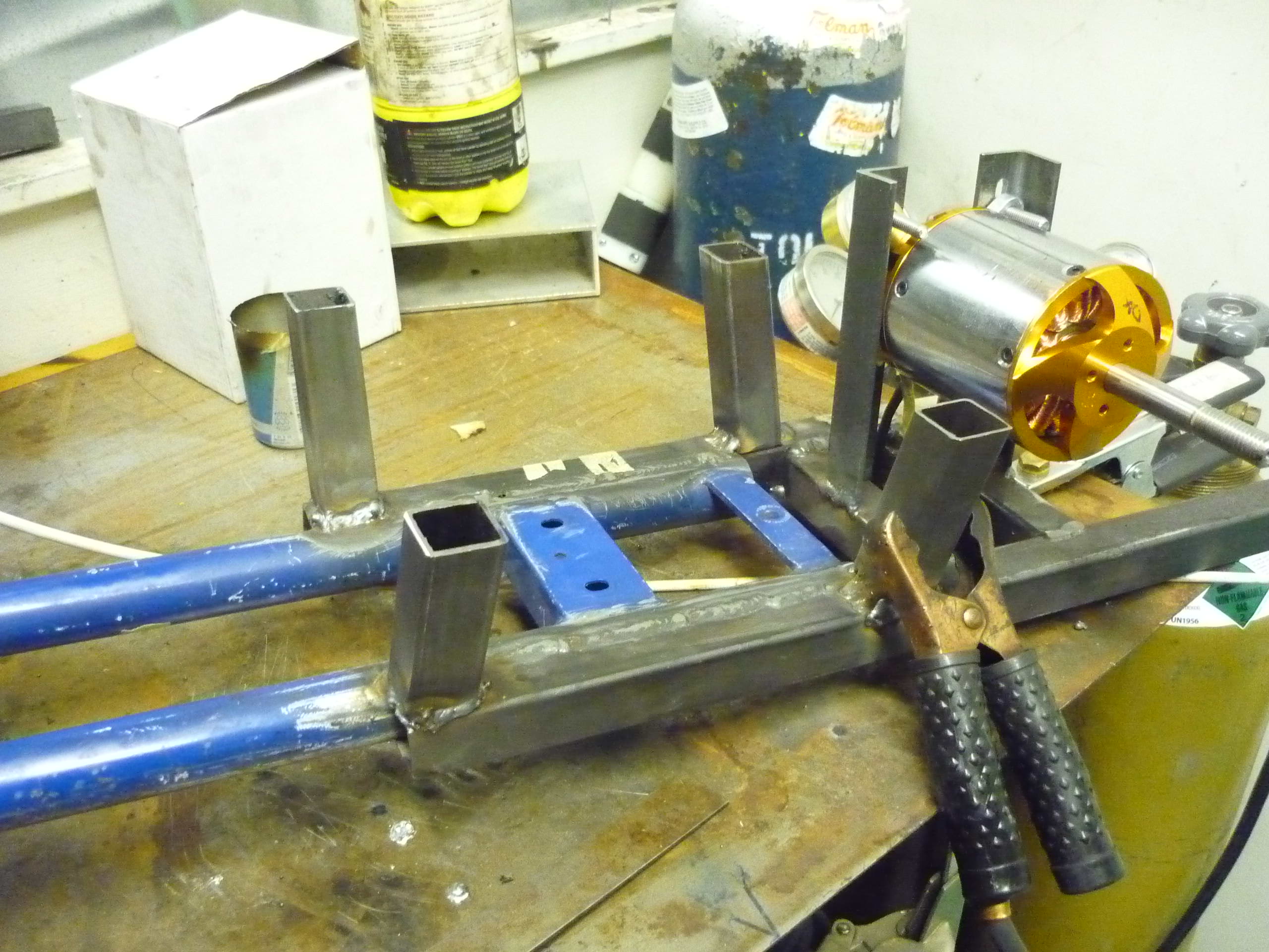
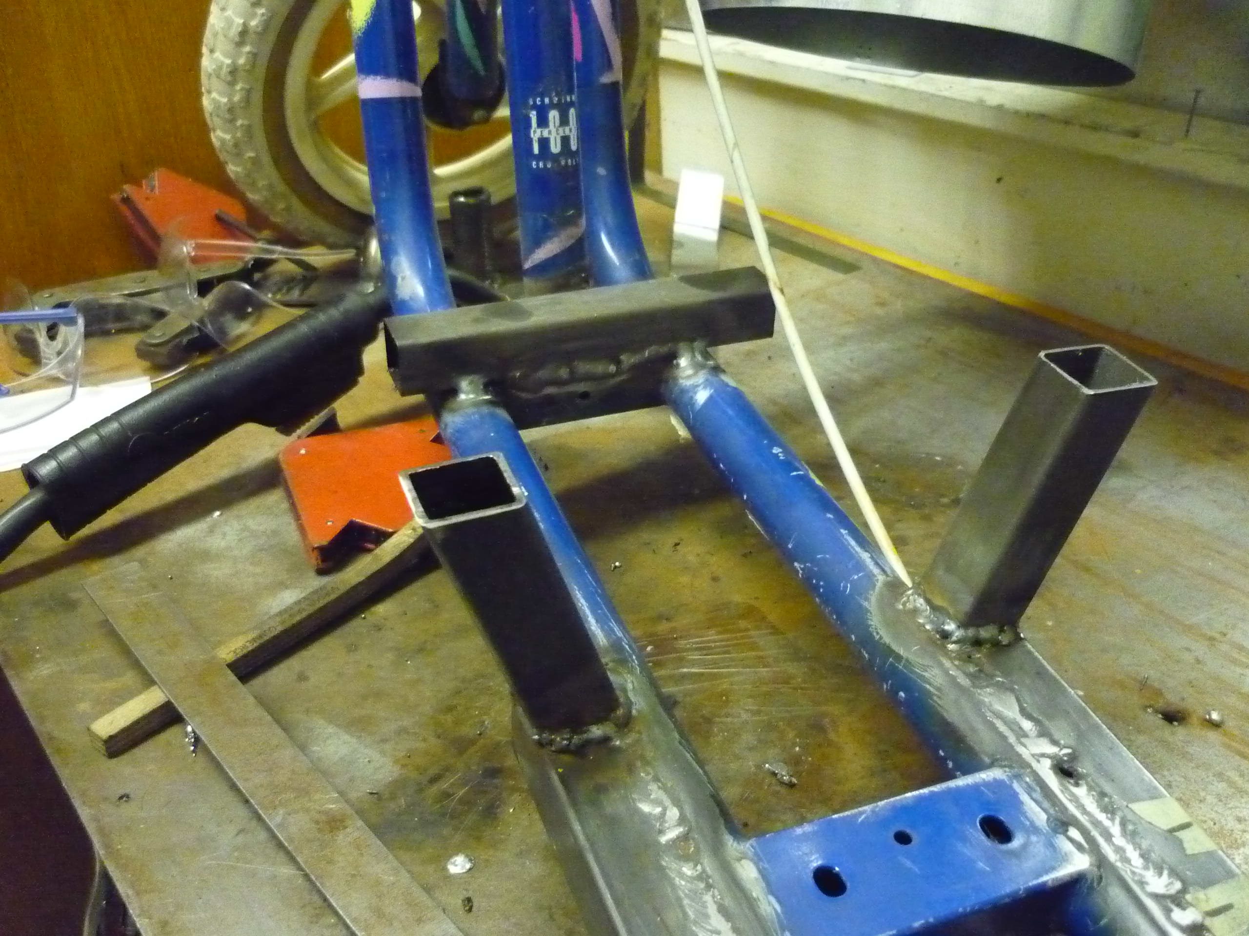
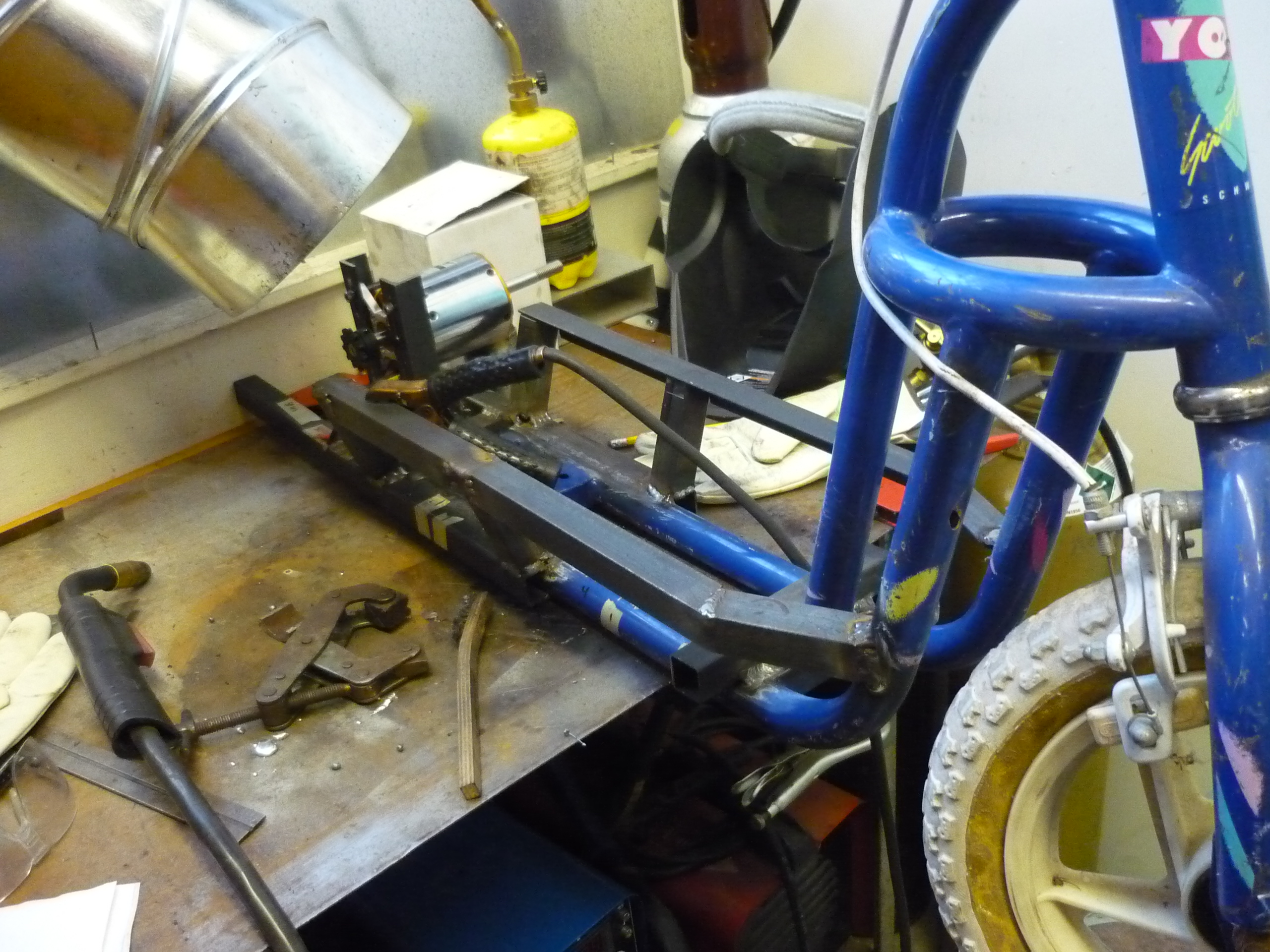
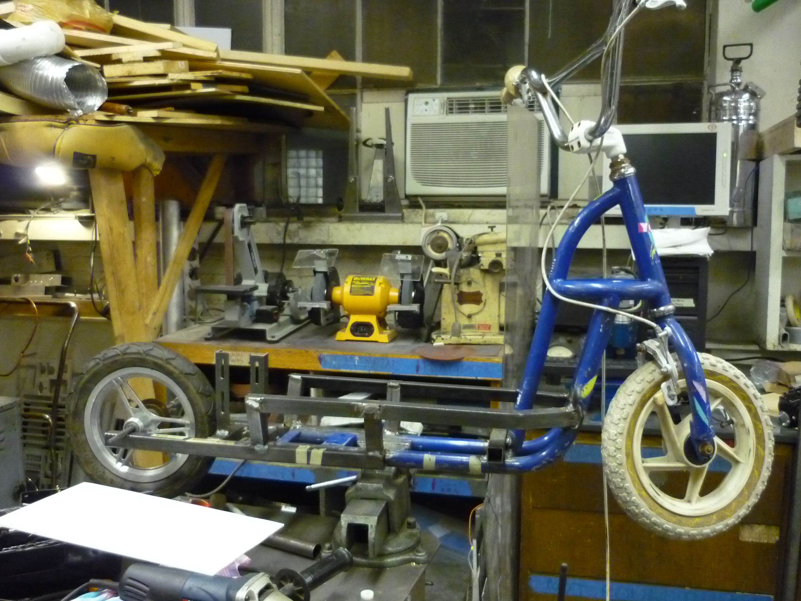
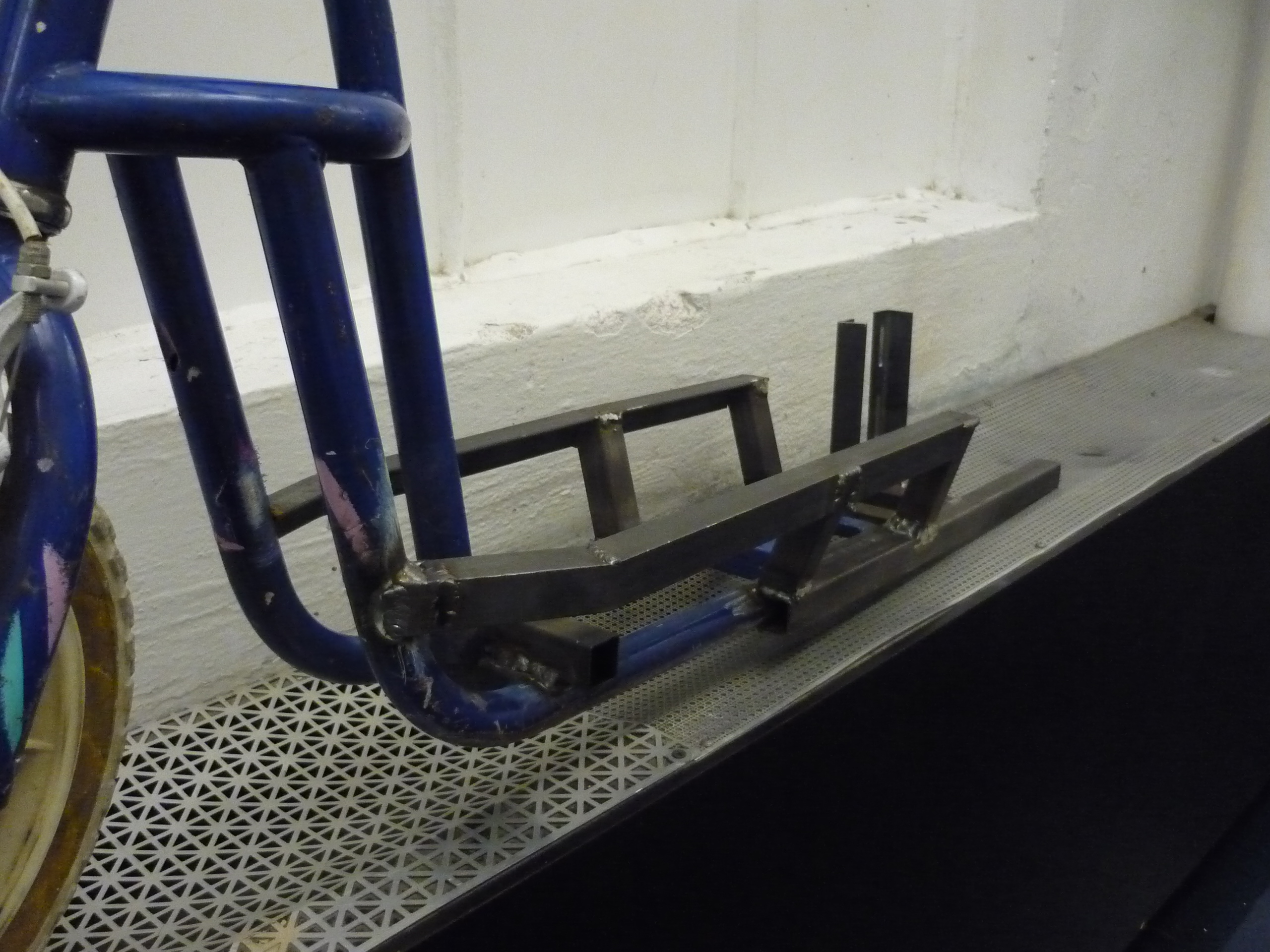
| More scooter please Two large square steel tubes were added to the back of the scooter frame. Fortunately because everything is steel, it was fairly easy to just weld-on extra length. |
 |
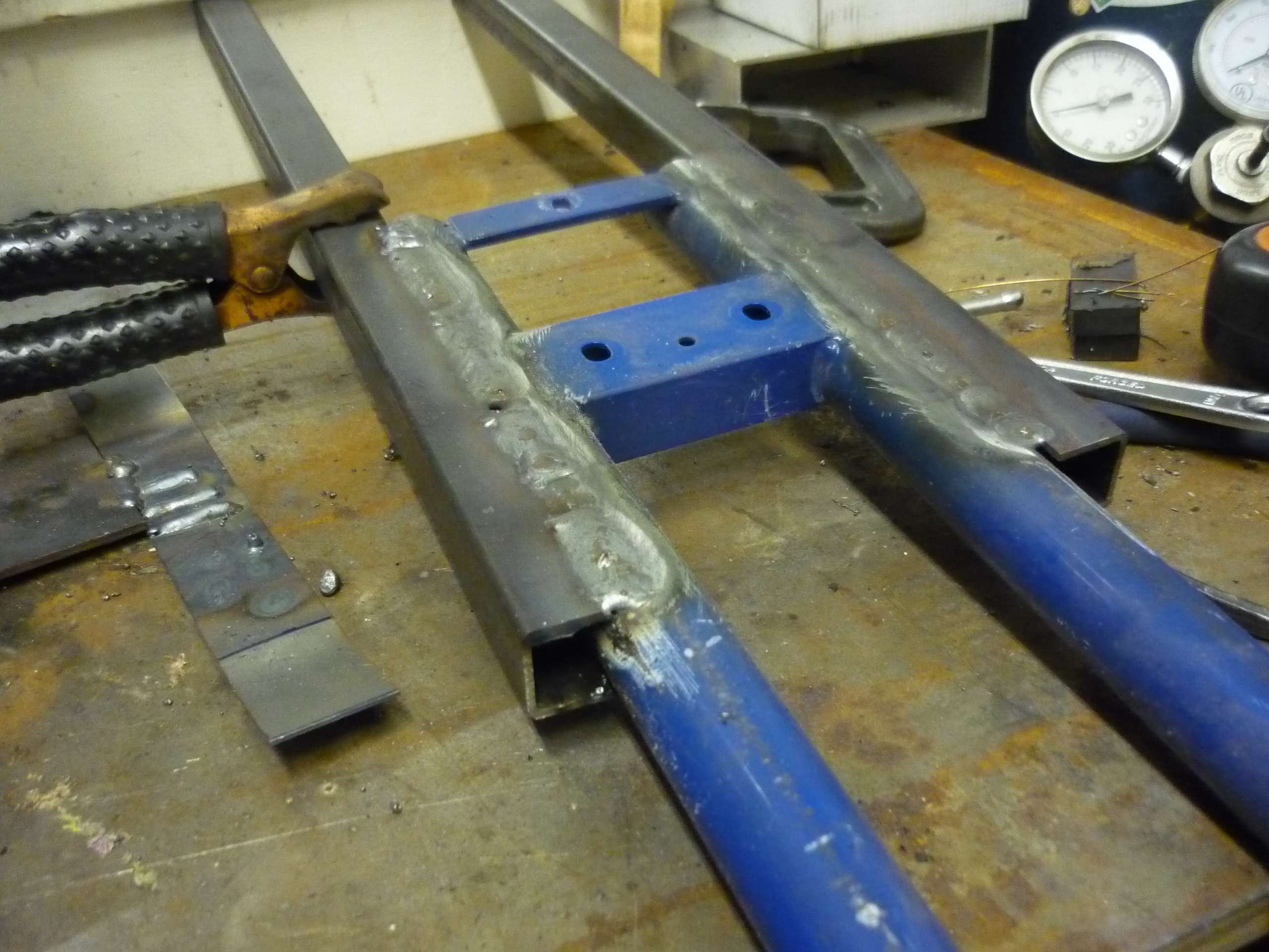 |
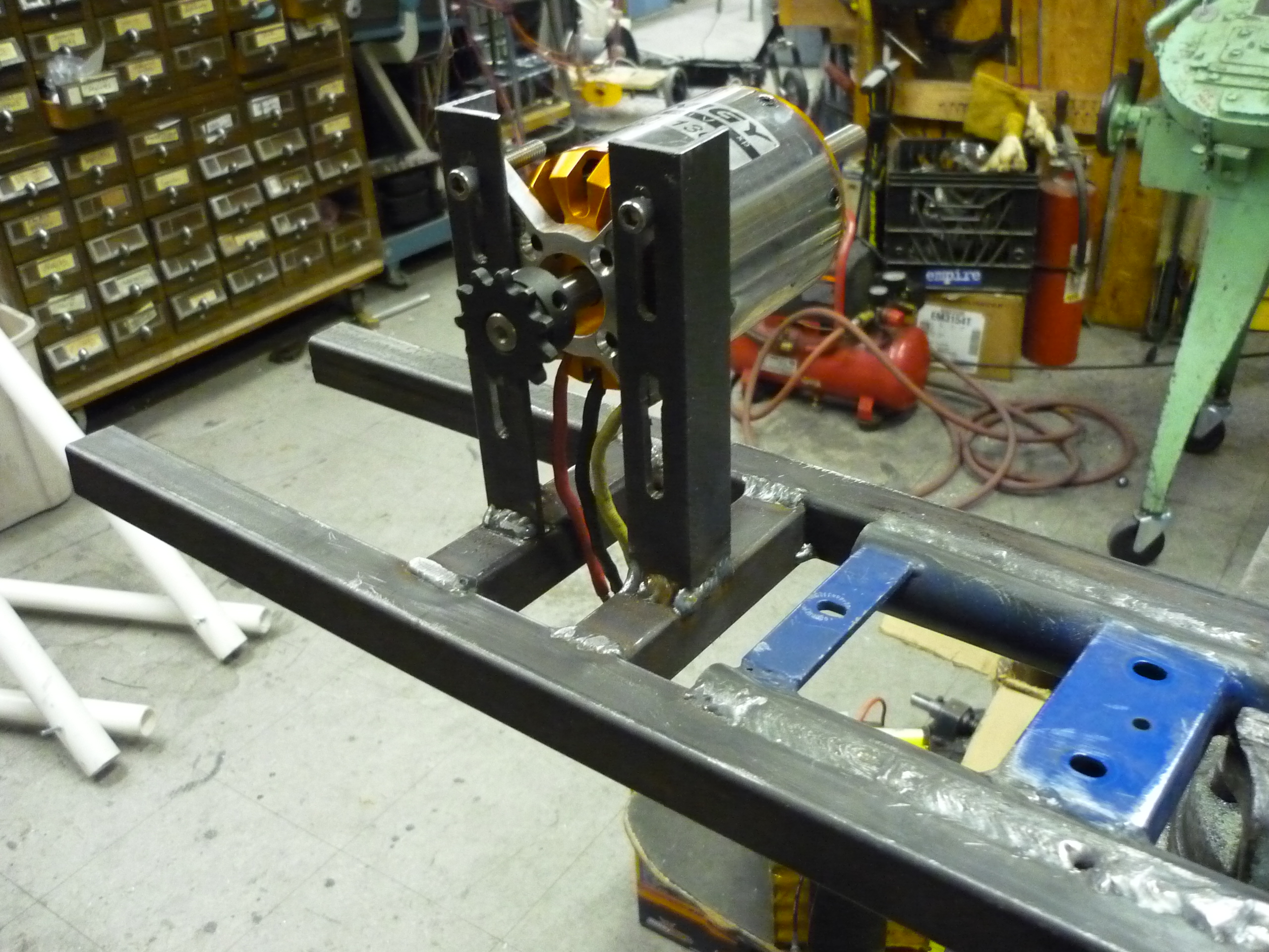
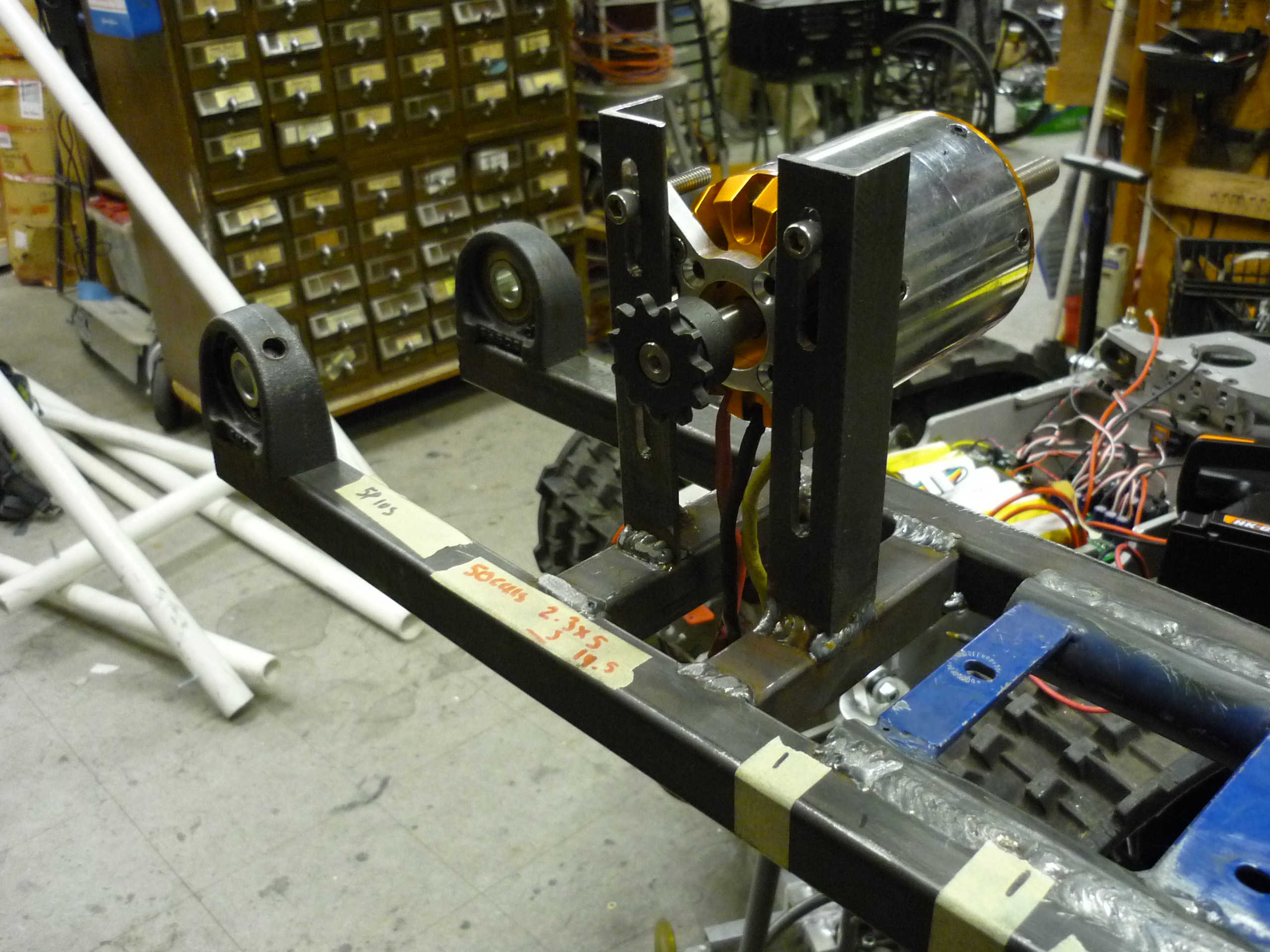
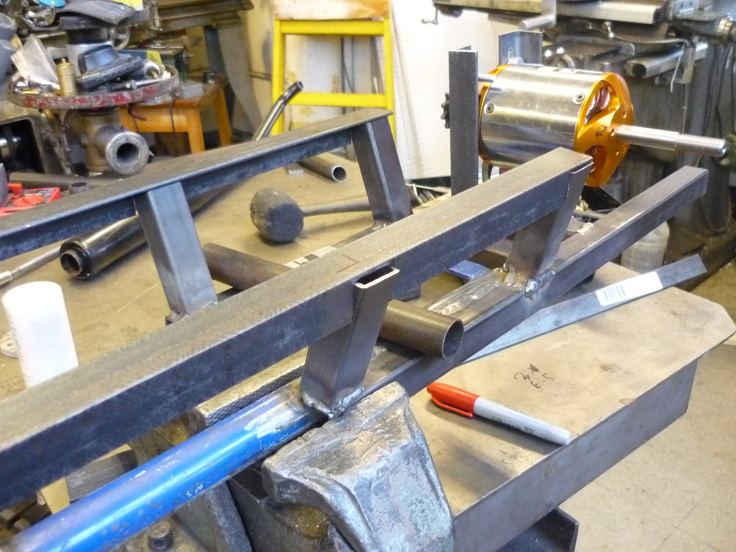
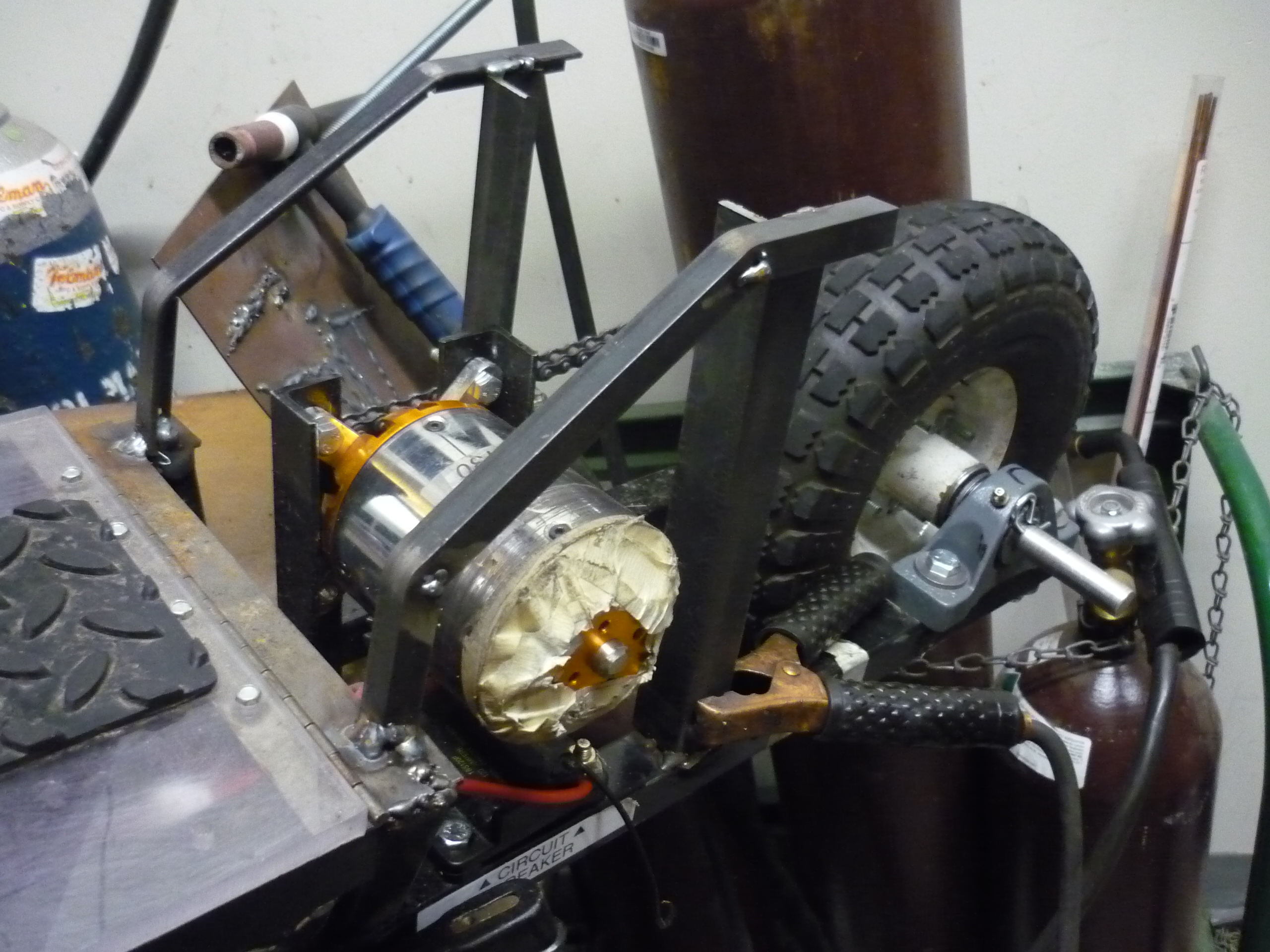
| Motor
Holster To hold the large motor in place i used a vertical milling machine and cut in slots corresponding to the bolt placement of the 3phase motor. The assembly can slide up/down to adjust for tension. When tightened the motor stays in place. |
 |
 |
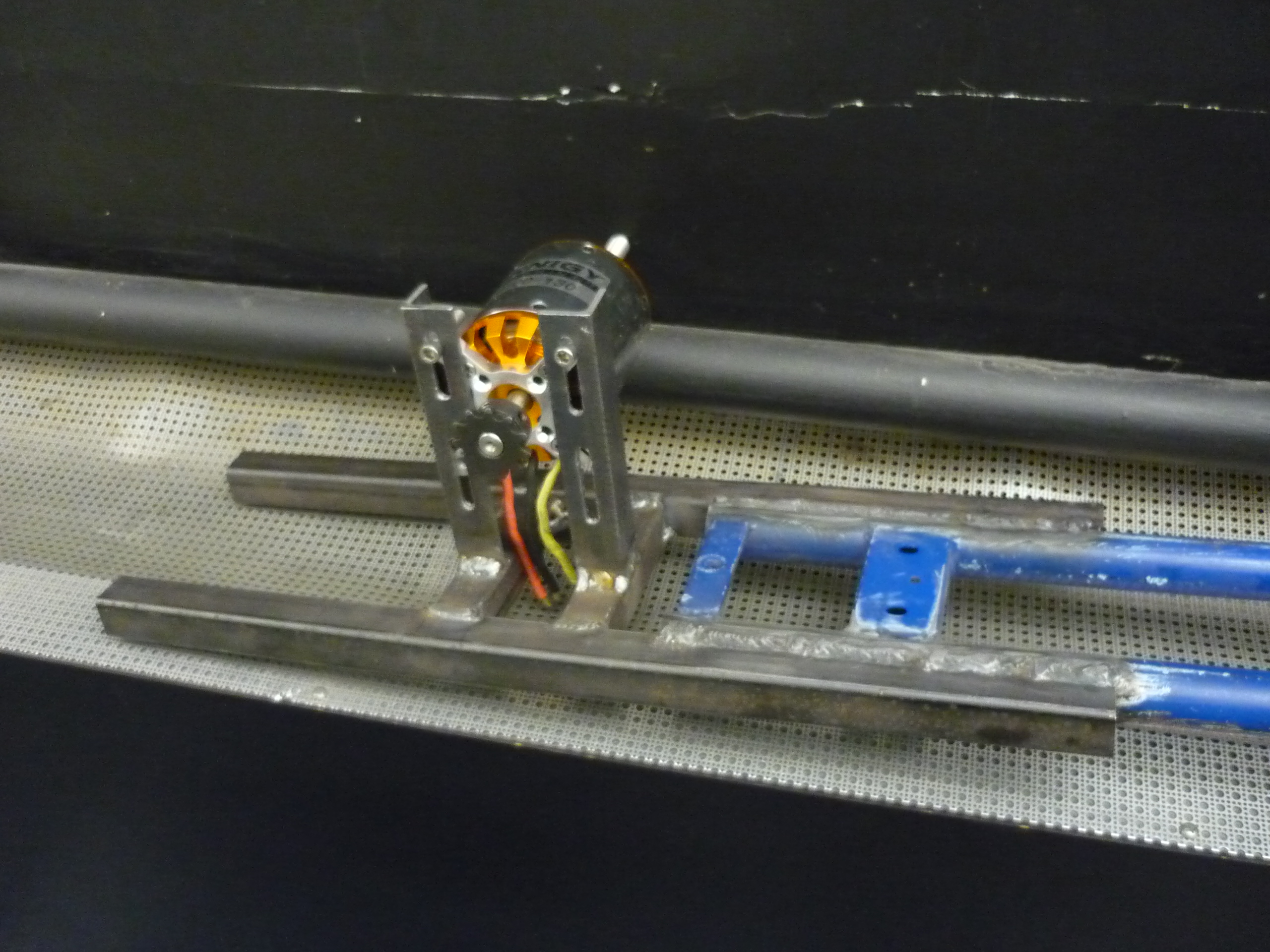
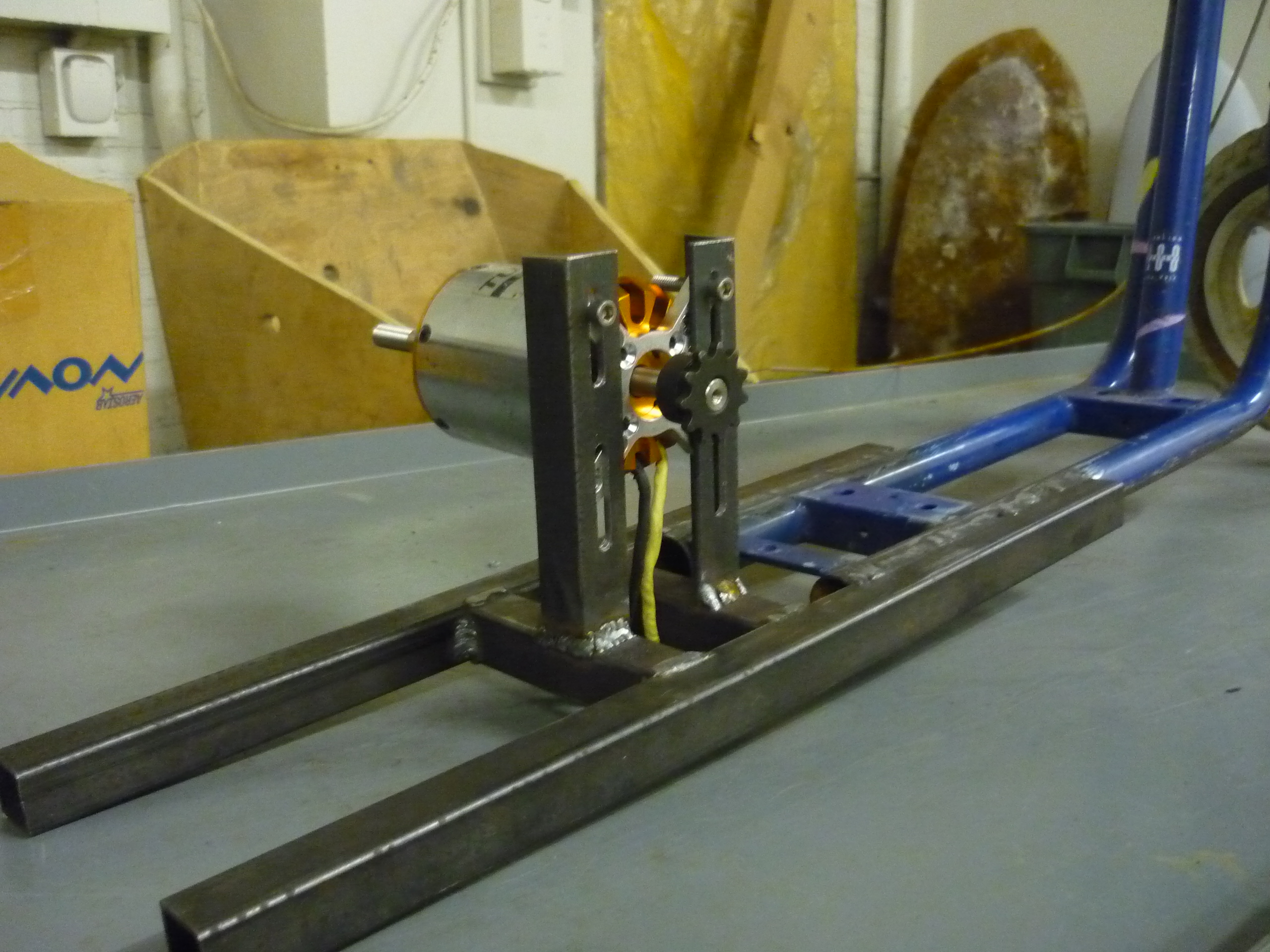
| More
Motor Holster Side-view of motor mount, before adding the rear wheel assembly. |
 |
 |
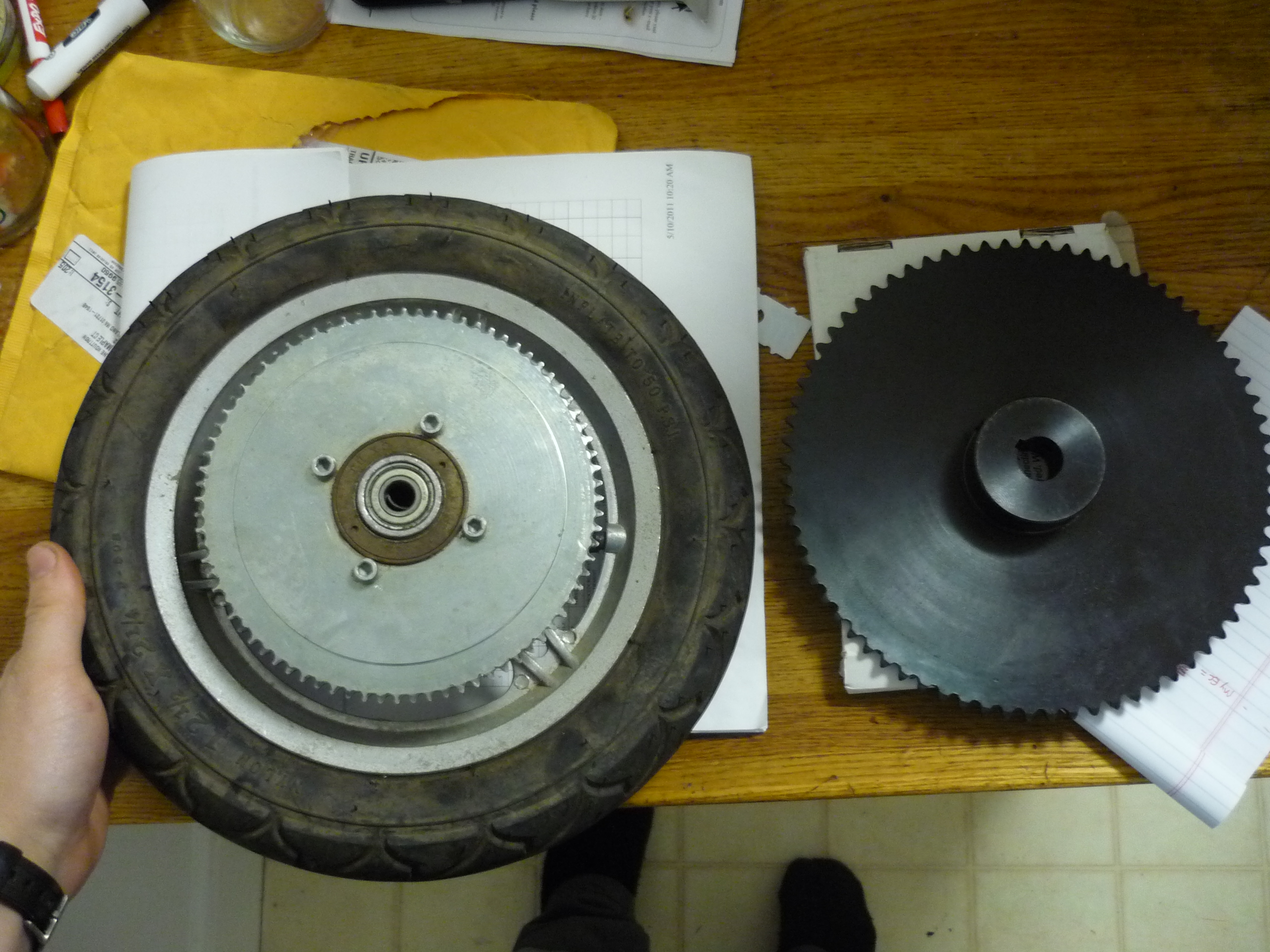
| DANE, WHY DO YOU KEEP USING
OVERSIZED SPROCKETS? Thats a good question. Shown left is the difference between a #25 sprocket and a #35 sprocket. #25 chain is very common on tiny-scooters, and it also is horrible, very stretchy, and extremely easy to become disengaged from the sprocket / motor. #35 is a lot bigger, and as such, to get any decent gearing, a huge sprocket is required. The sprocket was available from surplus center for cheap. (see bill of materials) |
 |
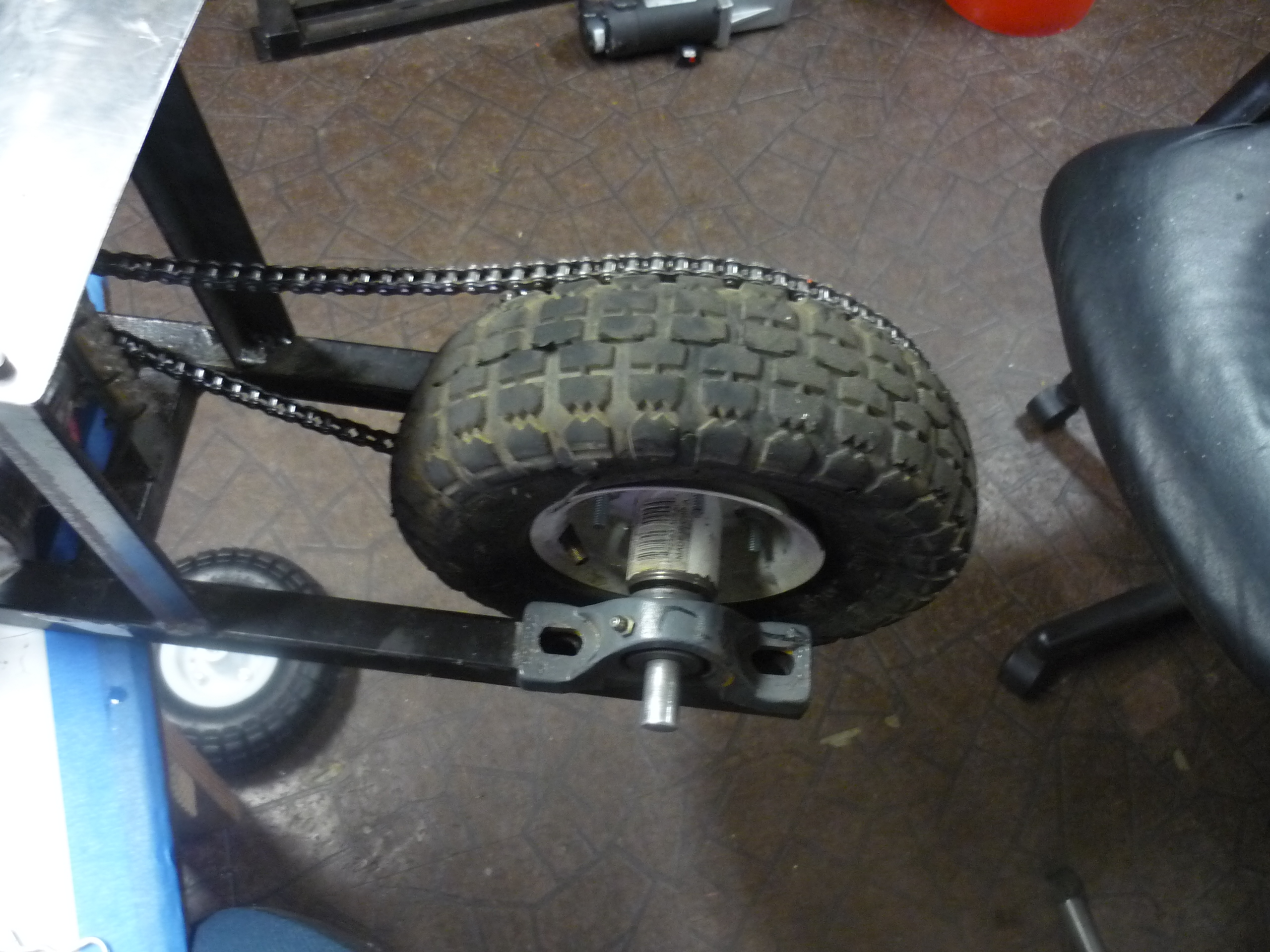 |
| Rear bearing assembly Initially i had opted for a smaller form-factor rear-bearing assembly, however due to the geometry of this bearing assembly, I ended up choosing a larger-format pillow-block bearing. The firt set of bearings used a 1/4-20 threading and, with loading, the force on the threads was borderline. A larger bearing was chosen instead (in bill of materials) |
 |
 |
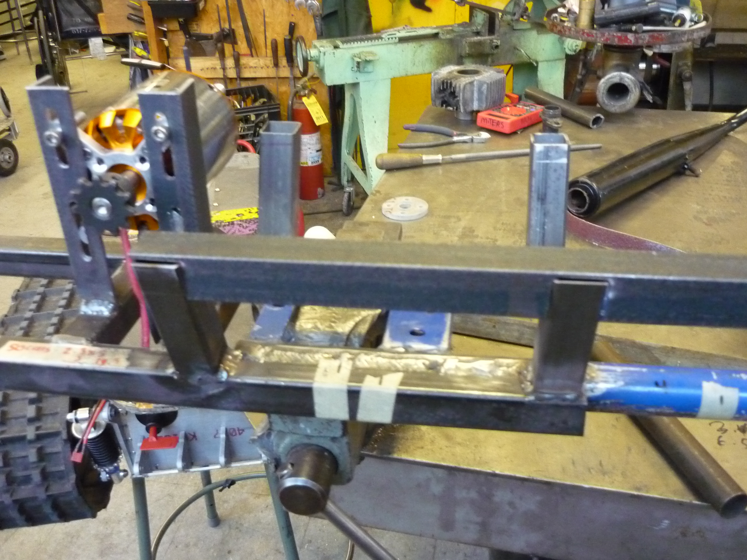
| The
Hull Note that this scooter assembly did not have a 'cad' diagram, a rough estimate of the size required for the battery and motor control assembly was completed on a napkin. Using a protractor and marked piece of string, i was able to make sure that the hull was roughly symmetrical. A brace for the front end was welded in place to act as a mating surface between the hull and the original frame assembly. |
 |
 |
| More
Hull Supports Equal sized struts were used for the hull assembly, they were each cut on a horizontal bandsaw to the same size before being tack-welded in place. With everything made of steel it was fairly easy to find a grounding point. |
 |
 |
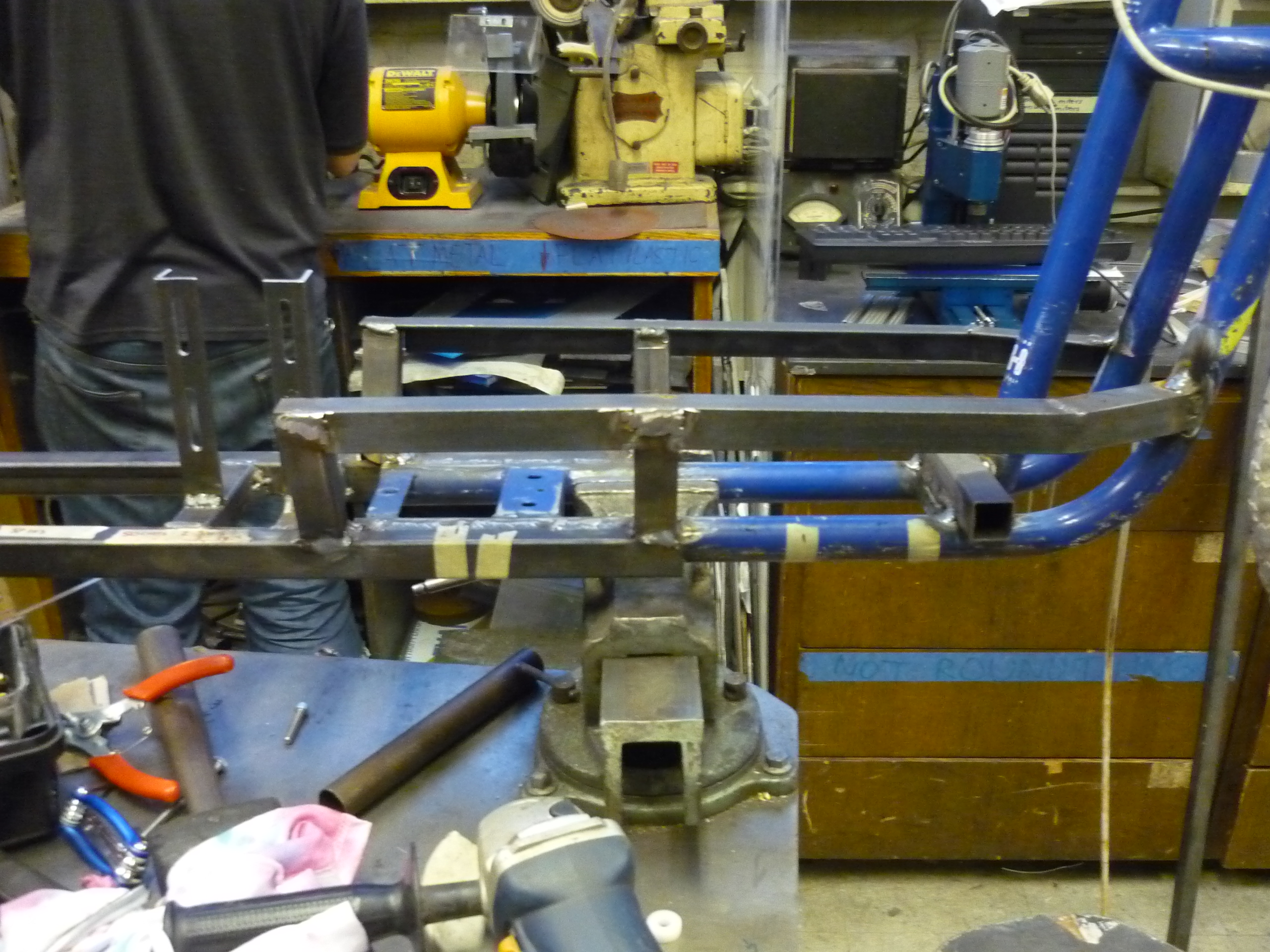
| More
Frame The sides of the hull are tack welded in place after a number of back-and-forth hacksawing, fitting, re-hacksawing and jamming into position. Each of the rails are made of steel angle-iron. That was available as scrap from another friend's awesome project. |
 |
 |
| Top
of the Hull The hull of the battery bay was made to be sturdy, i tried to have as much weld-able contact area between the two surfaces, as this would allow for a stronger shell. |
 |
 |
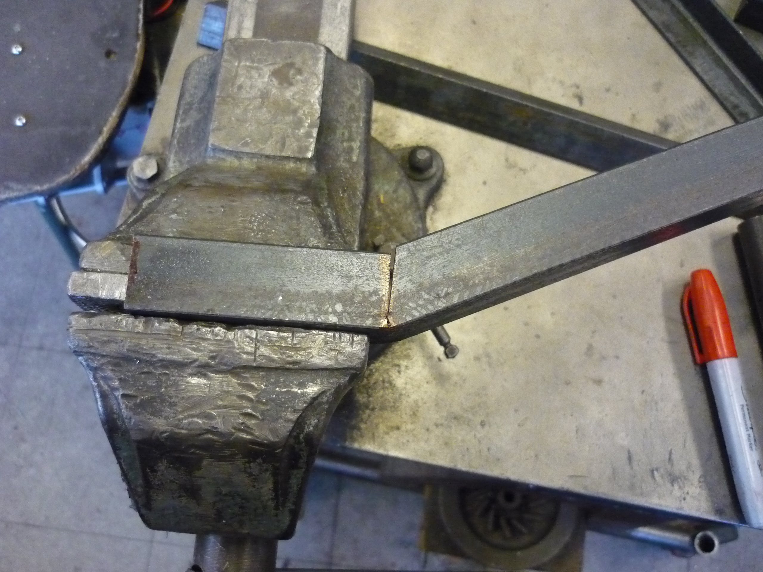
| Hull-frame
connection Everything shown was hack-sawed into shape, which resulted in a number of trips back and forth to the miters vice. |
 |
 |
| Welding
the hull together With the hull held together by clamps, tack welds were made to keep the frame shape during welding. After 20 minutes, the shell was completely welded up. After filing for a few minutes to get rid of any rough edges, the hull was born! |
 |
 |
| A
mockup and more weld-shots Note the angle parts of the frame were sliced with a hacksaw and re-welded together. |
 |
 |
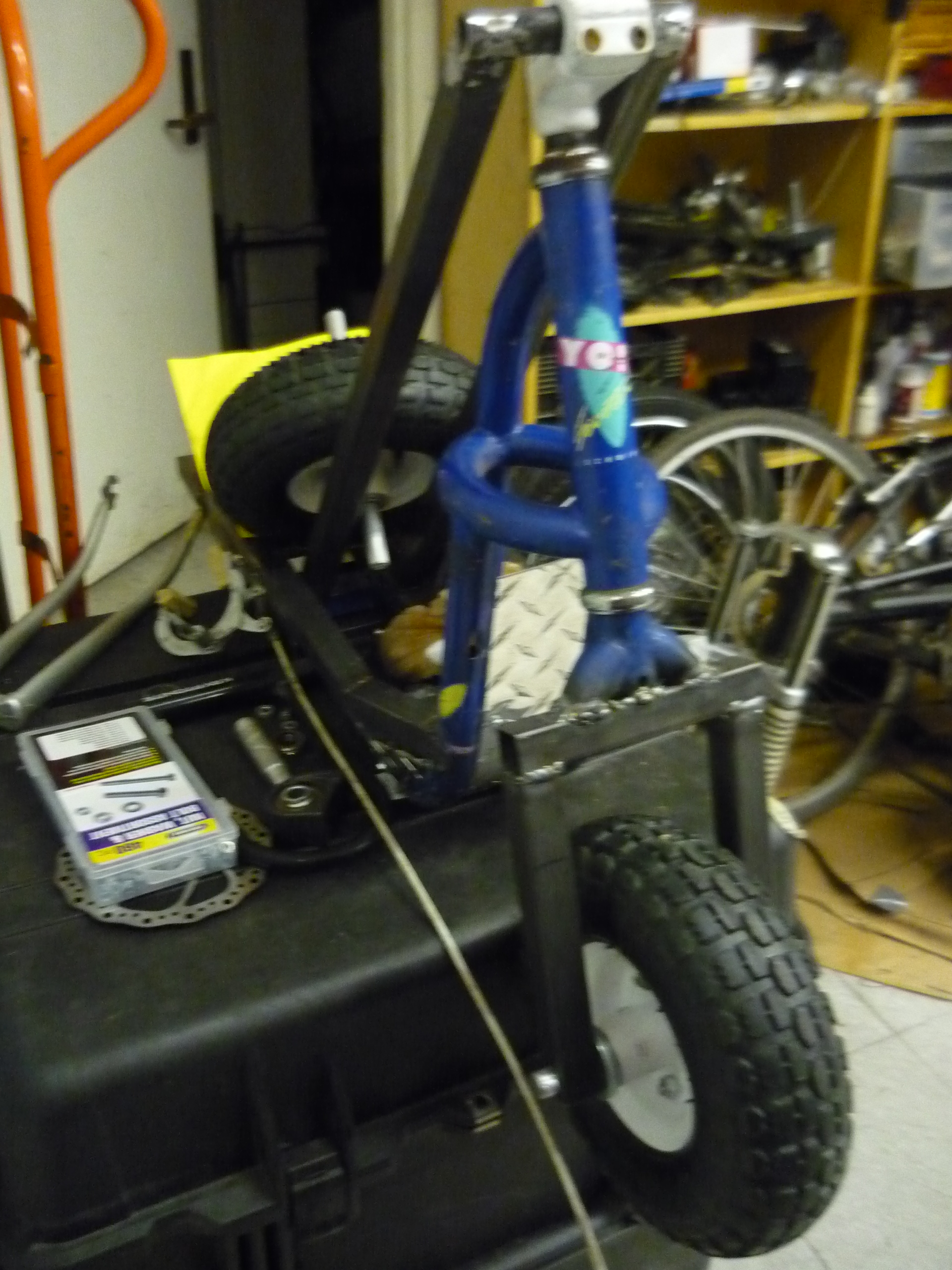
| Front
wheel assembly The original front wheel was ~8" tall and targeted towards the small children from an episode of full house, so i chopped off the wheel holster and quickly threw together a very very basic wheel holster. The spacer holding the wheel in the center is a lathed piece of delrin plastic. |
 |
 |
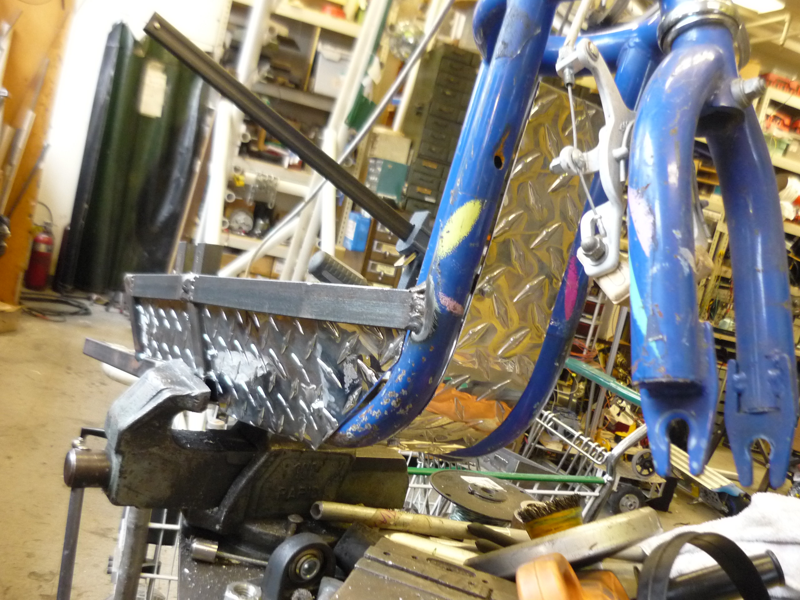
| Adding
Diamond-plate to cover the hull 12" square sheets of aluminum stamped diamond plate were used to fill in the hull's open areas. After paint they contrasted fairly well. |
 |
 |
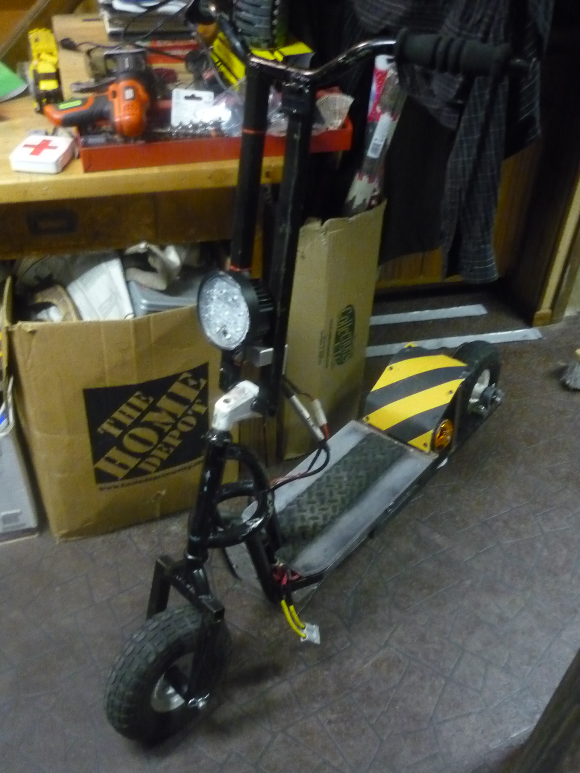
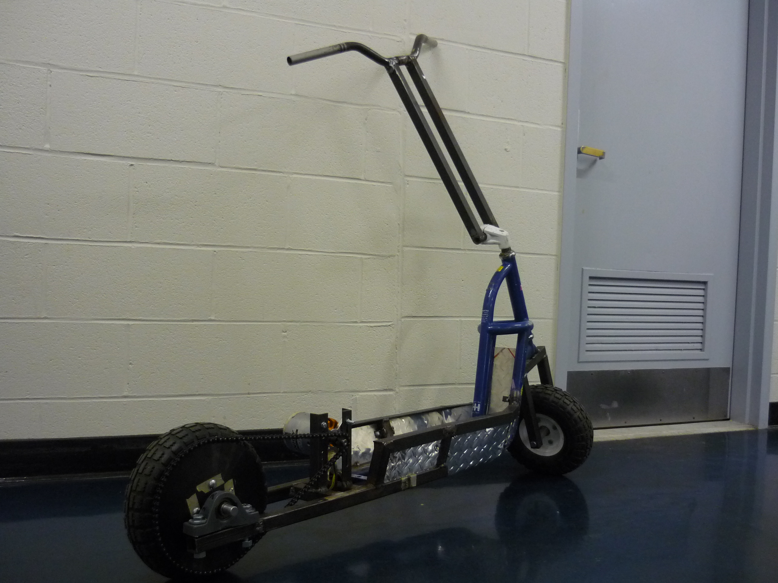
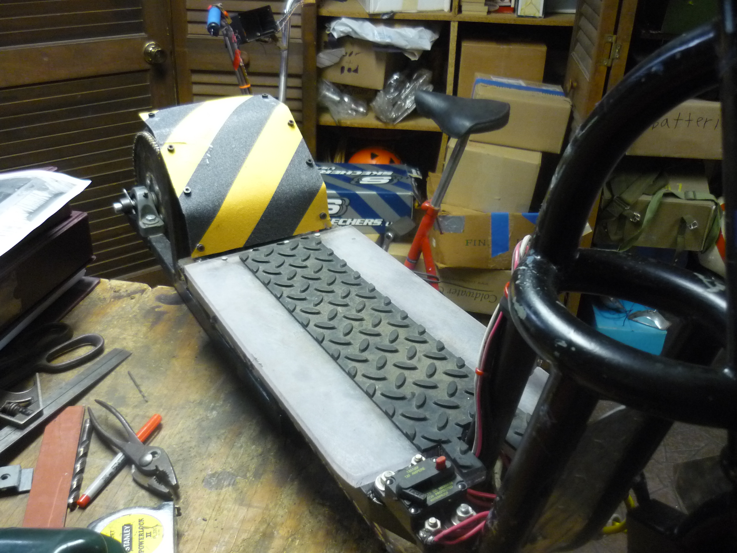
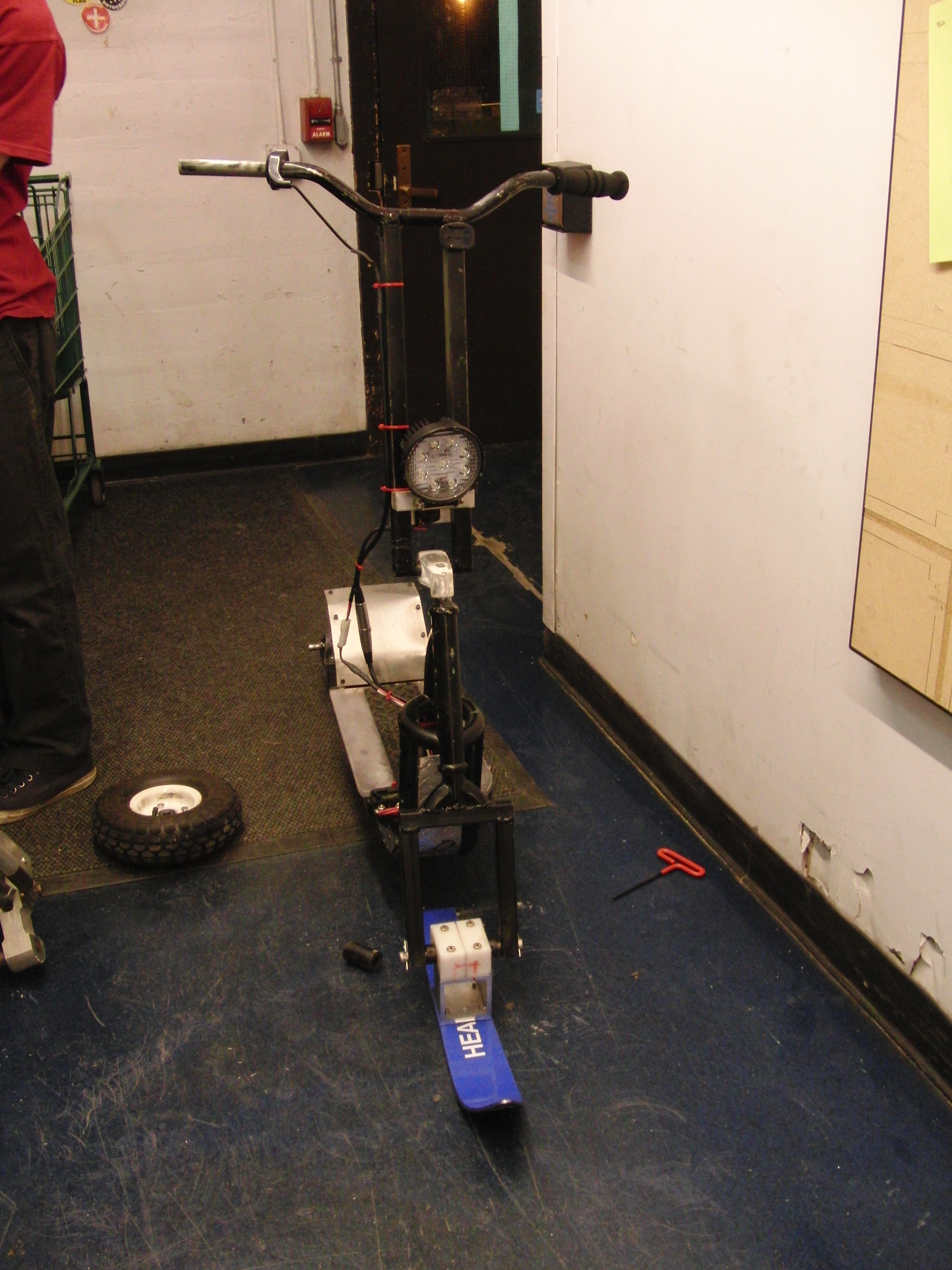
| Pre-paint
scooter assembly More glamor shots of the beast |
 |
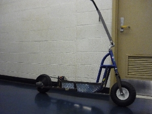 |
| Pre-paint
scooter assembly Well doesnt that look dangerous! |
 |
 |
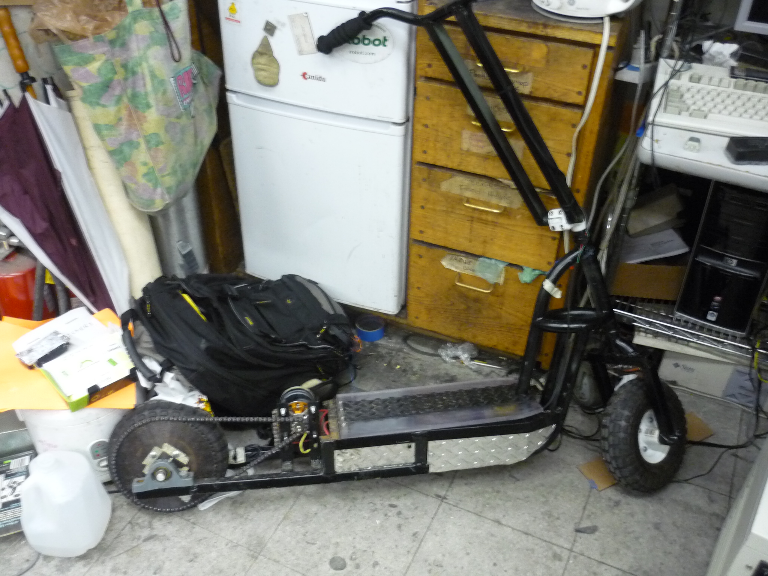
| Post-painting
assembly Sitting in miters near the fridge, circa 2012 |
 |
 |
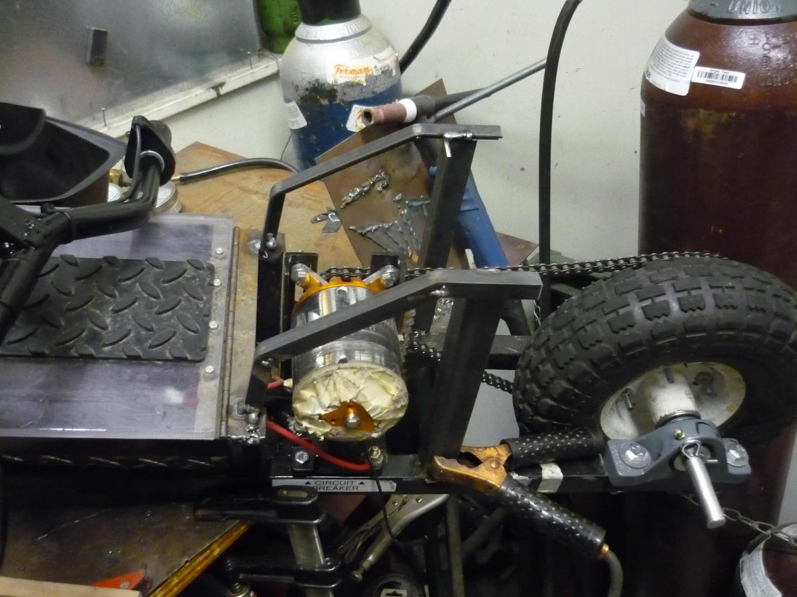
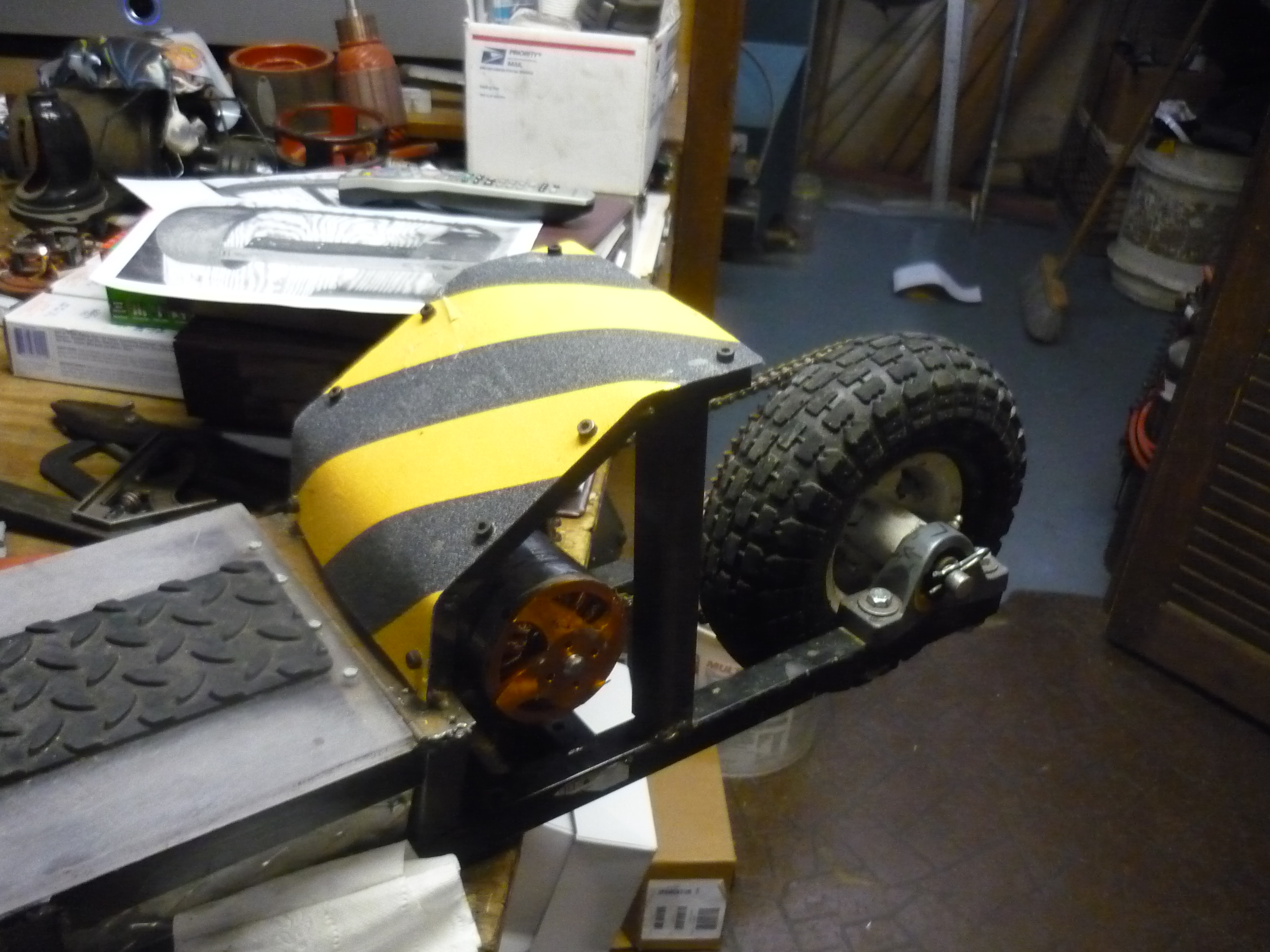
| Motor
Cover cage The motor assembly lacked a cover, which made it fairly easy to get a foot or pant leg caught. In fact it is an excellent size to rip a pant right off while riding in public. This needed to be addressed. |
 |
 |
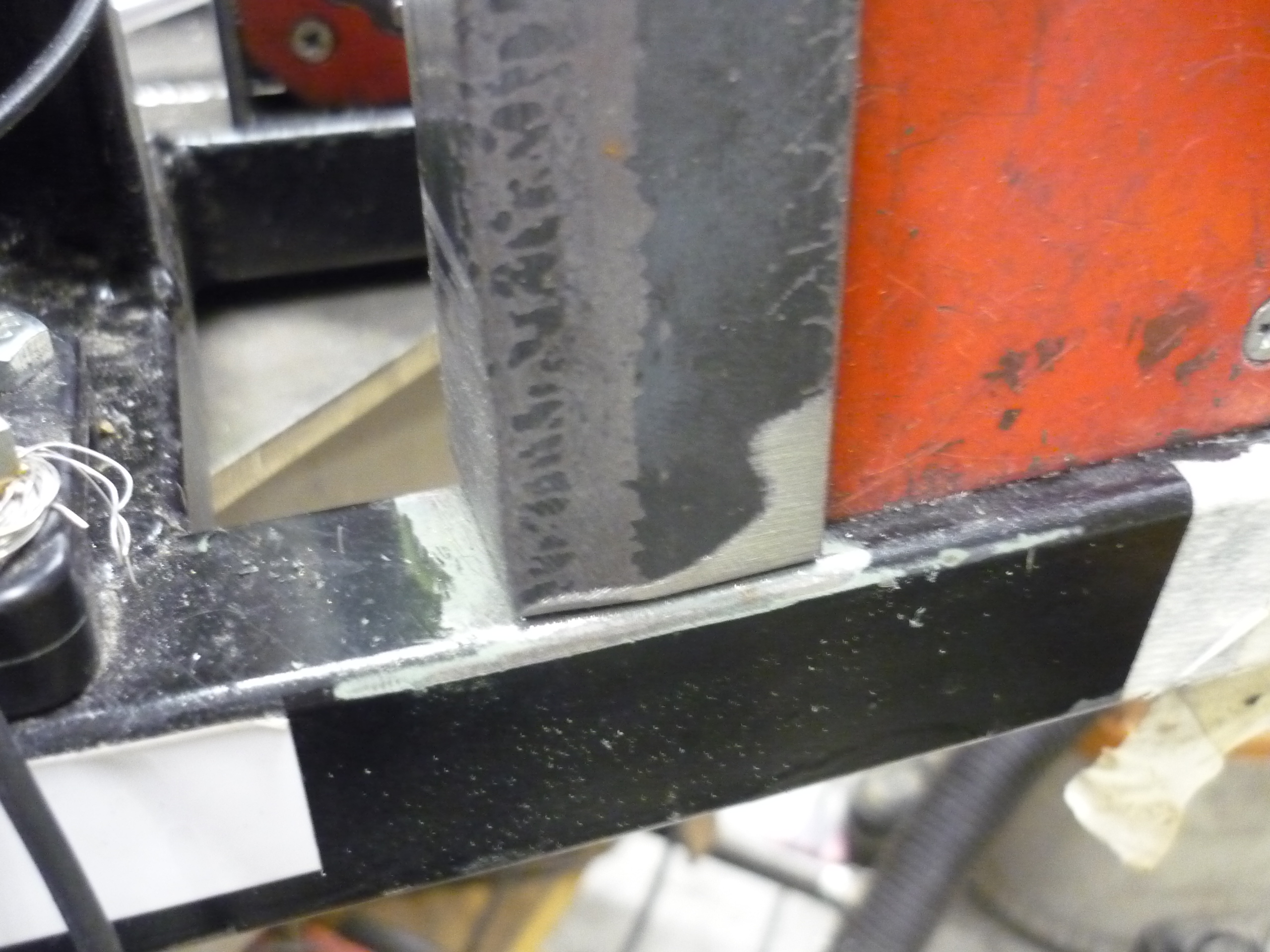
| Magnet
clamps and steel After finding some angle iron and sanding down painted area of the frame, two 1" wide pieces of steel were tacked onto the base frame. |
 |
 |
| Some
mig-welding later... The rear motor-shield was tack-welded onto the frame base. I used the same mig-welder with cover argon mix cover gas. It turned out I needed to sand away more material to get a really good bond, but once the steel was hot, it was a quick matter of brushing off the paint! |
 |
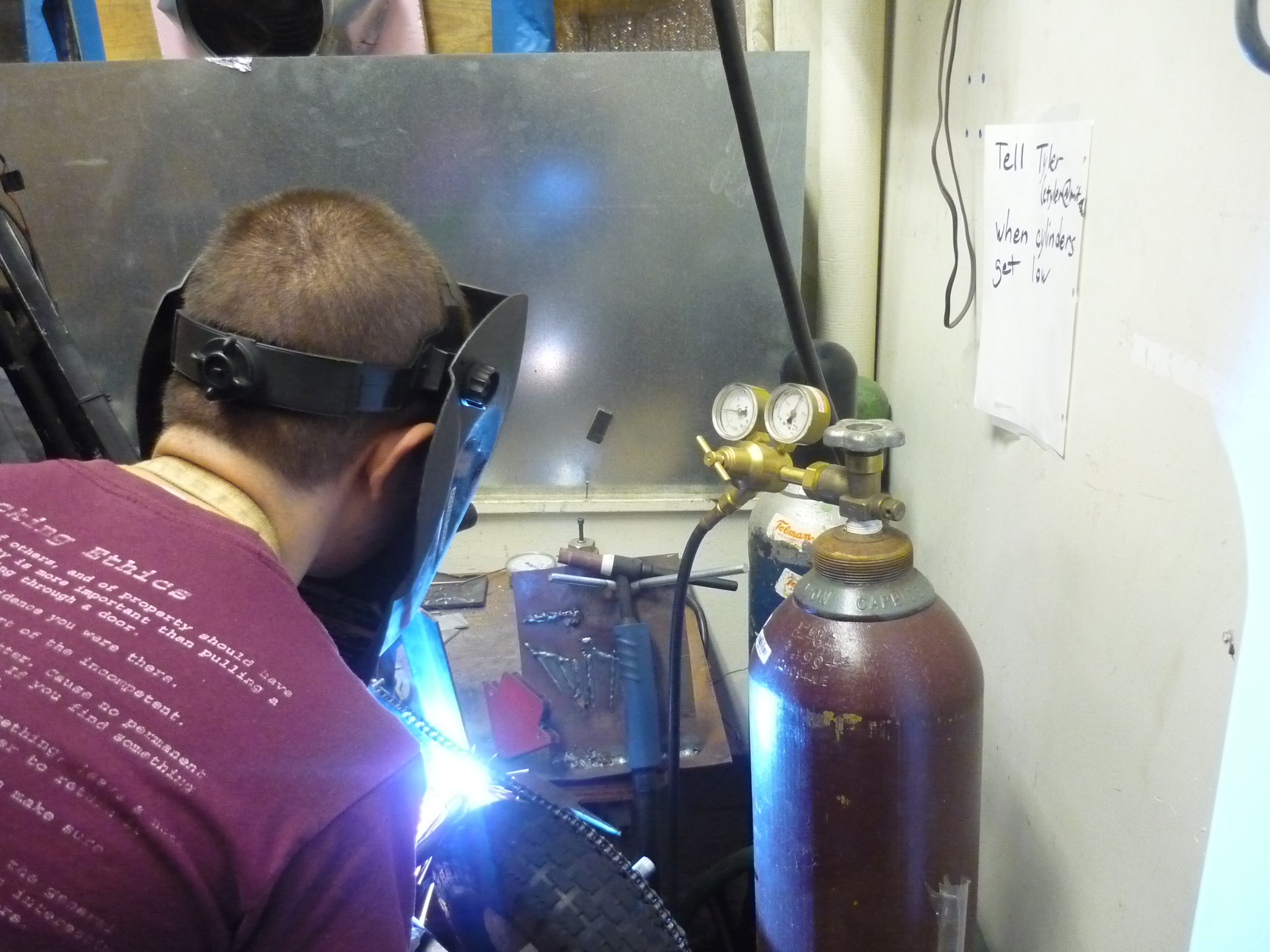 |
| Motor
cage bars 1/4 inch steel angle iron was grinded, bent and tacked in place to form an outer cage around the motor. This was tack welded to form a cage. As this is a structural component, leaning on this while riding, and it maintaining its shape is key. Everything was mig-welded in place, and a 'hammer test' was used to make sure impacts would not pose a hazard. |
 |
 |
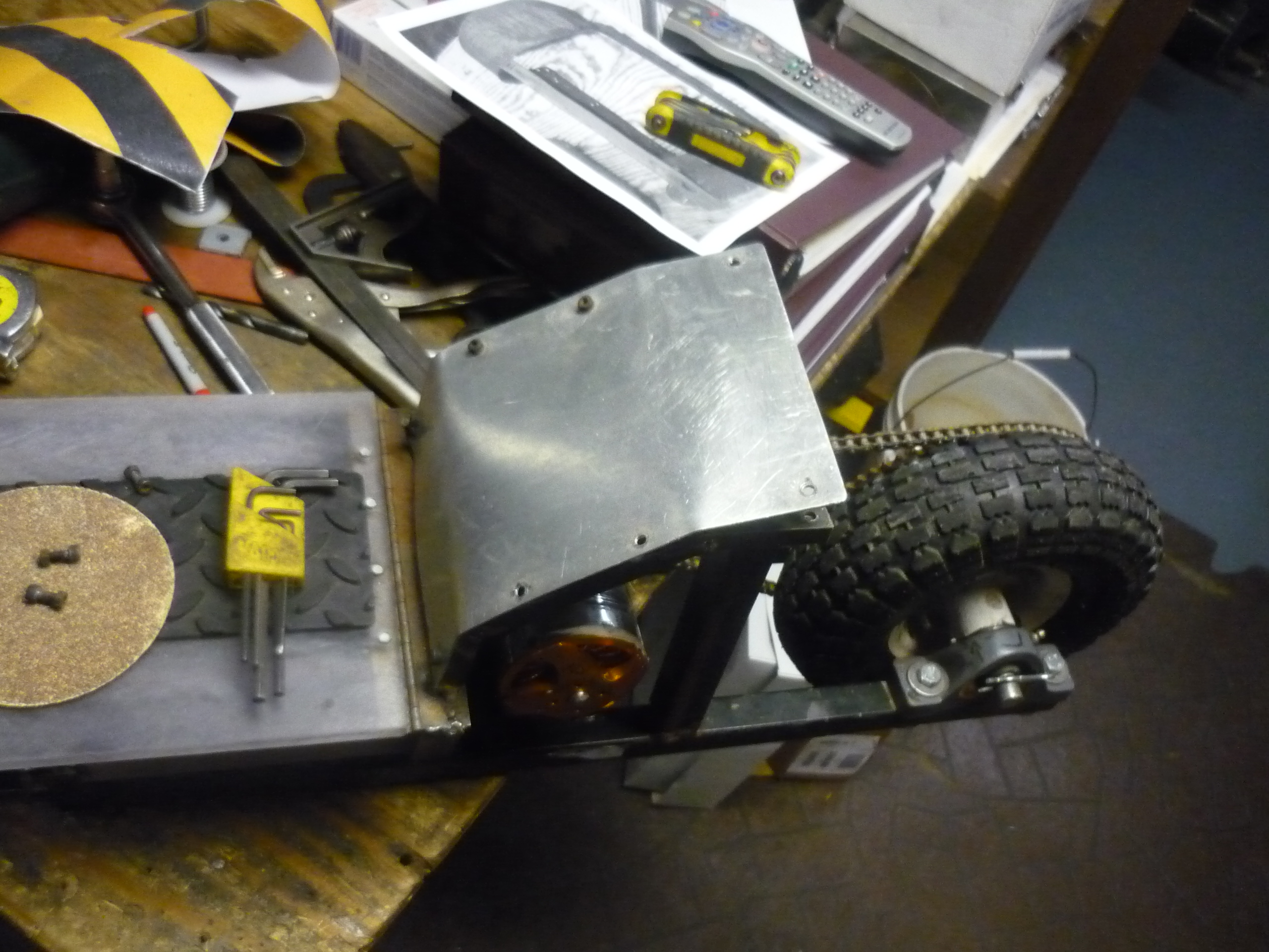
| Top
Cover I used 1/16th " thick aluminum plate to cover the rear-wheel assembly. In conjunction with some M5 hex cap screws it was fairly quick to put together, and provided some excellent coverage from the highspeed motor housed underneath. |
 |
 |
Primer & Paint
| What |
||
| To paint the frame, I used a self-etching primer, in combination with some hard-epoxy appliance paint (think refrigerator paint). The primer is fantastic, after sanding down the initial blue paint from the frame, I hung the assembly in a garage, applied a coat of primer, tooled on other things for a few hours, and came back to find a really-well applied, dry, coating. As a note, the drying is very temperature dependent, I significantly doubt that it would have worked as expediently in the freezing cold. | 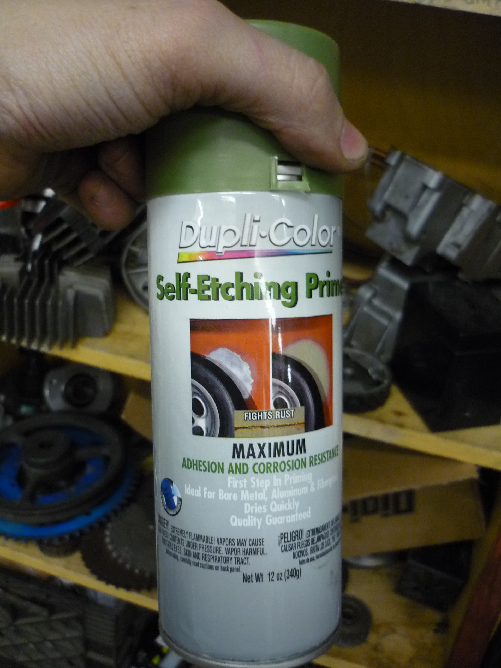 |
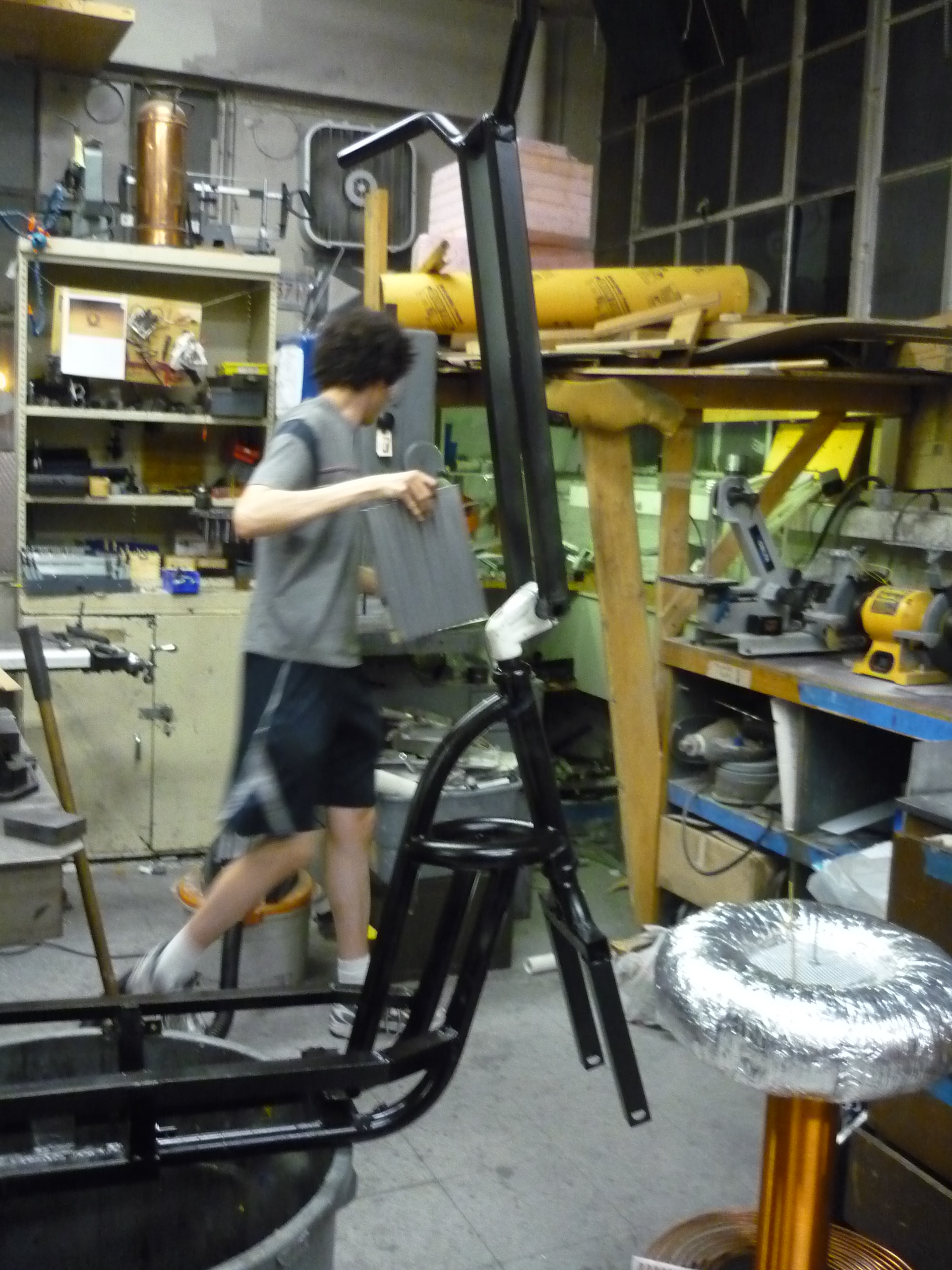 |
| SO
FANCY The frame, mostly dry, sitting on the floor / near the windows. The black paint really worked well on the frame. It hung precariously by a piece of wire for 10 hours until i took it down, i think the cold weather kept it from tacking up for a while. In the end it turned out well, and it was fairly difficult to chip away any paint. |
 |
 |
| Re-assembled After the paint dried, i re-assembled most of the frame components, wheels and steering assembly. It was surprising, but everything fit back together fairly well without any 'surprise' extra bolts / nuts. I noticed that some extra braces were needed on the aluminum hull panels and tacked in small braces to keep everything from jostling around while underway. |
 |
 |
Range & PowerTesting
| What |
||
| To get an accurate power / range test, I purchased a 130A RC watt-meter, and added the same power-pole connectors used on the battery input. During range-tests this was added in series with the system (between the battery and the scooter). Its a fantastic device, it loggs peak power, peak current and performs rough coloumb counting to determine battery amp-hours consumed.During one of the outdoor testing runs, I found that the controller peaked at 110A, and 3.8 kw. |  |
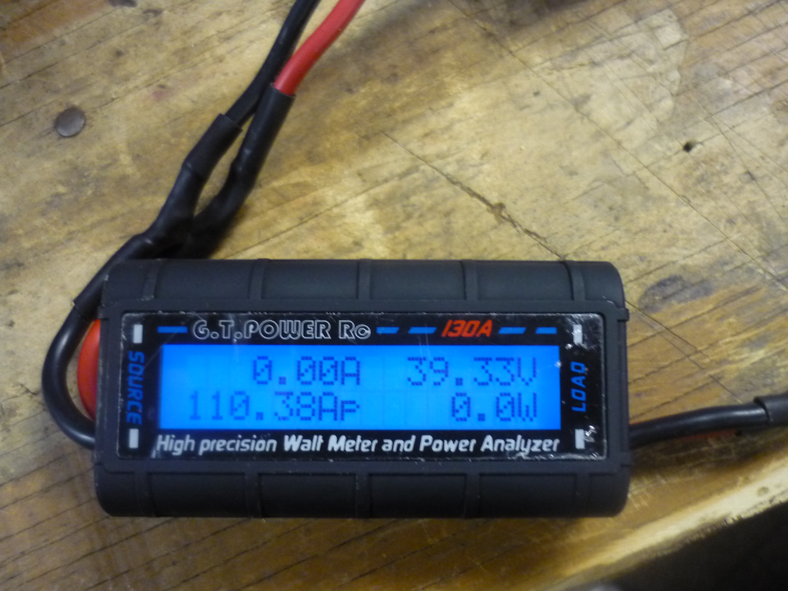 |
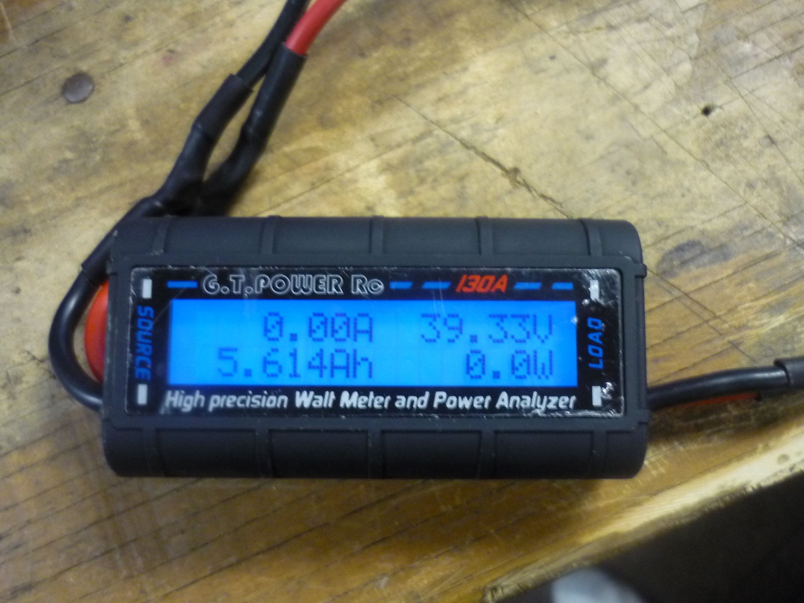
| During the same run, I found that, during the roughly 4.4 mile run (up and down hills, and along the beach) the scooter pulled ~5.6 ampere-hours. This is effectively 51 watt-hours / mile, which was surprisingly, a lot lower than expected. At roughly 0.7 miles / amp-hour, the scooter, should have a roughly 7 mile range. | 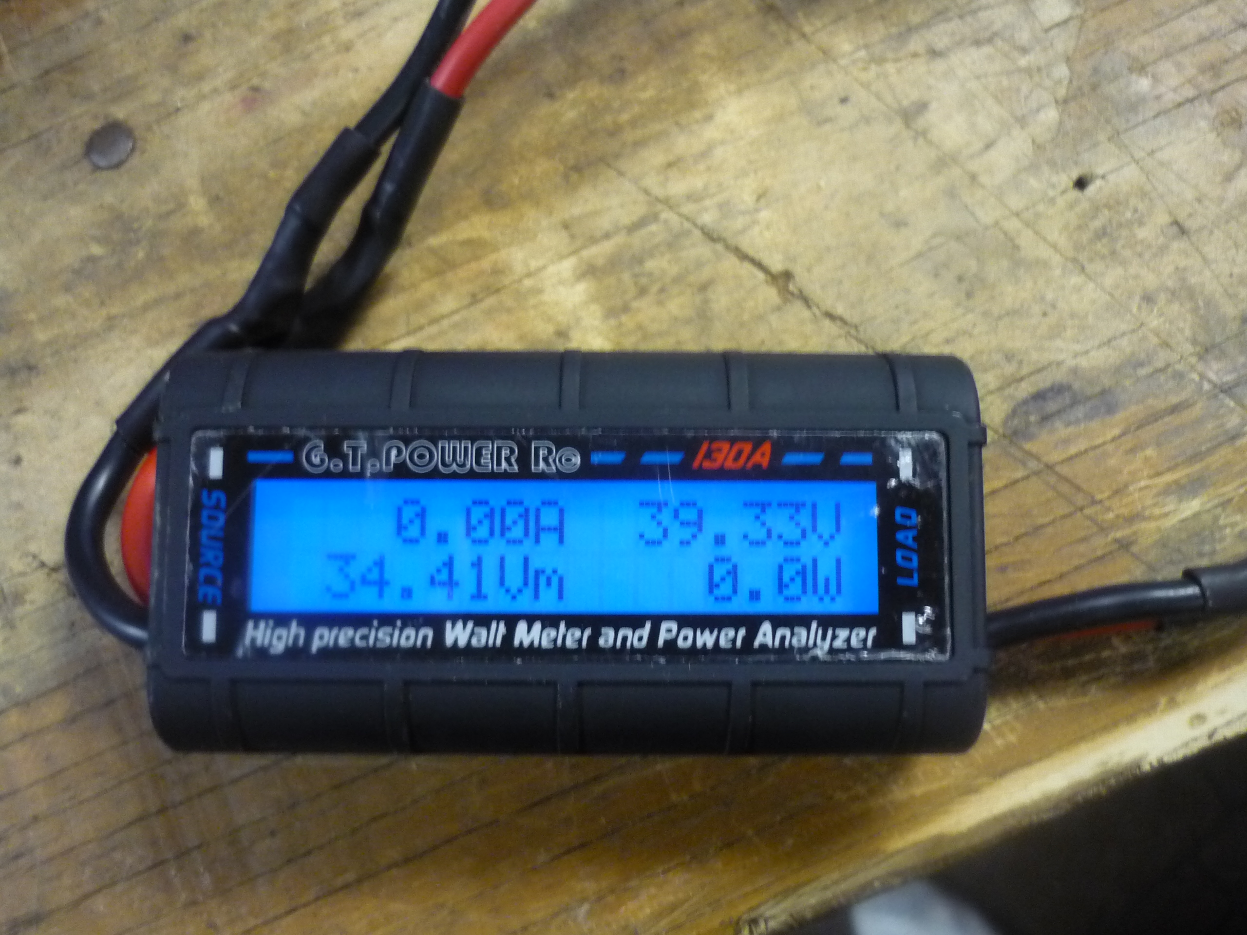 |
 |
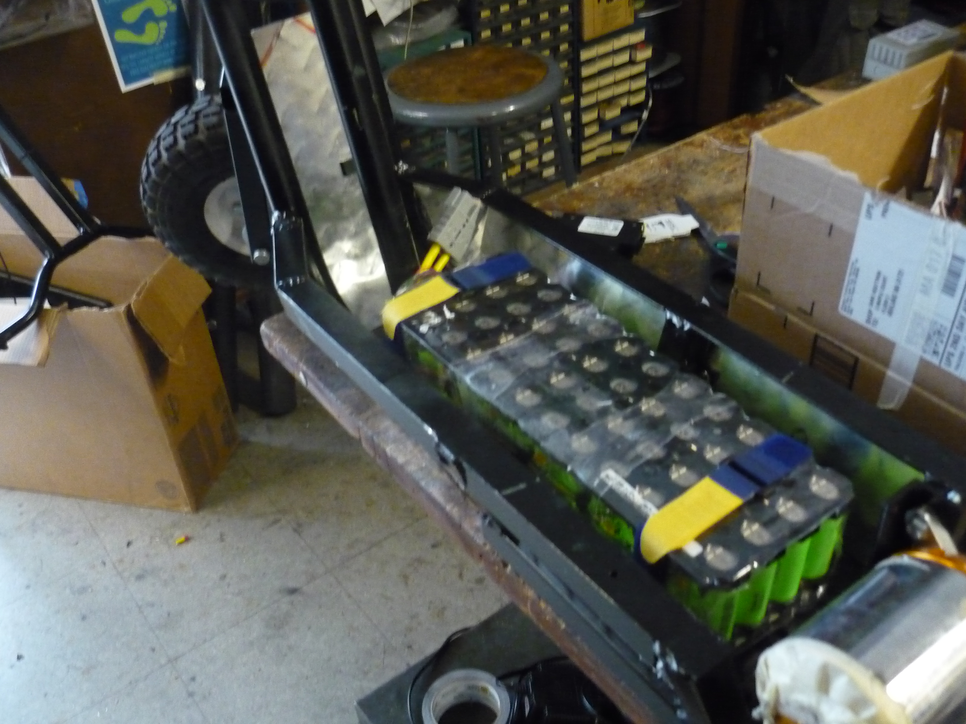
The Battery Module: Sodabottle Armor
| What |
||
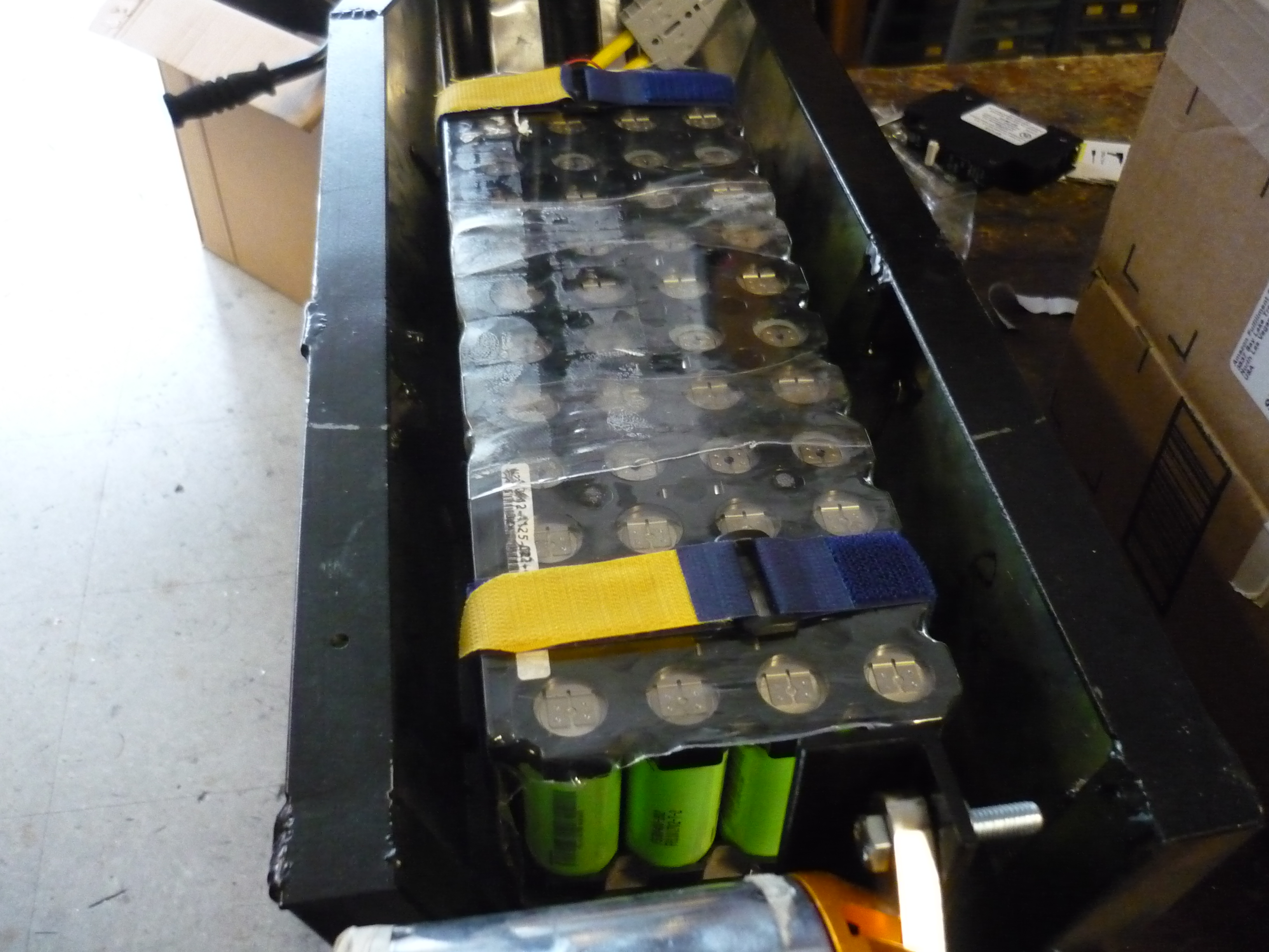
| Using a technique from the folks in battlebot land, I found that a 3L soda-bottle (PET plastic), worked excellent as a 'hard shell' medium for the module. The battery modules were scrapped A123 12S 4P modules, that were deactivated, and after asking nicely, allowed to be used in strange 'Dane side-projects'. |  |
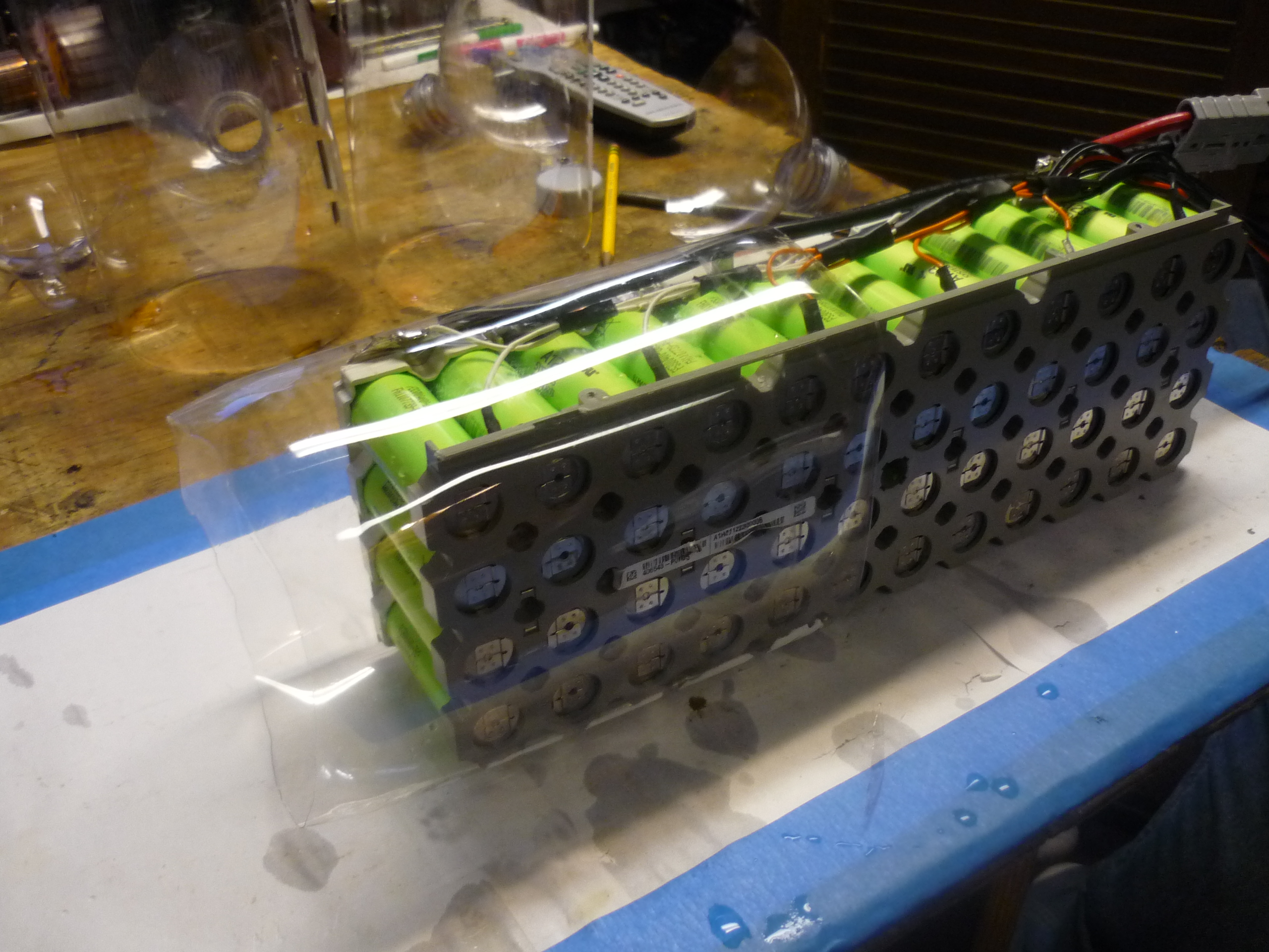 |
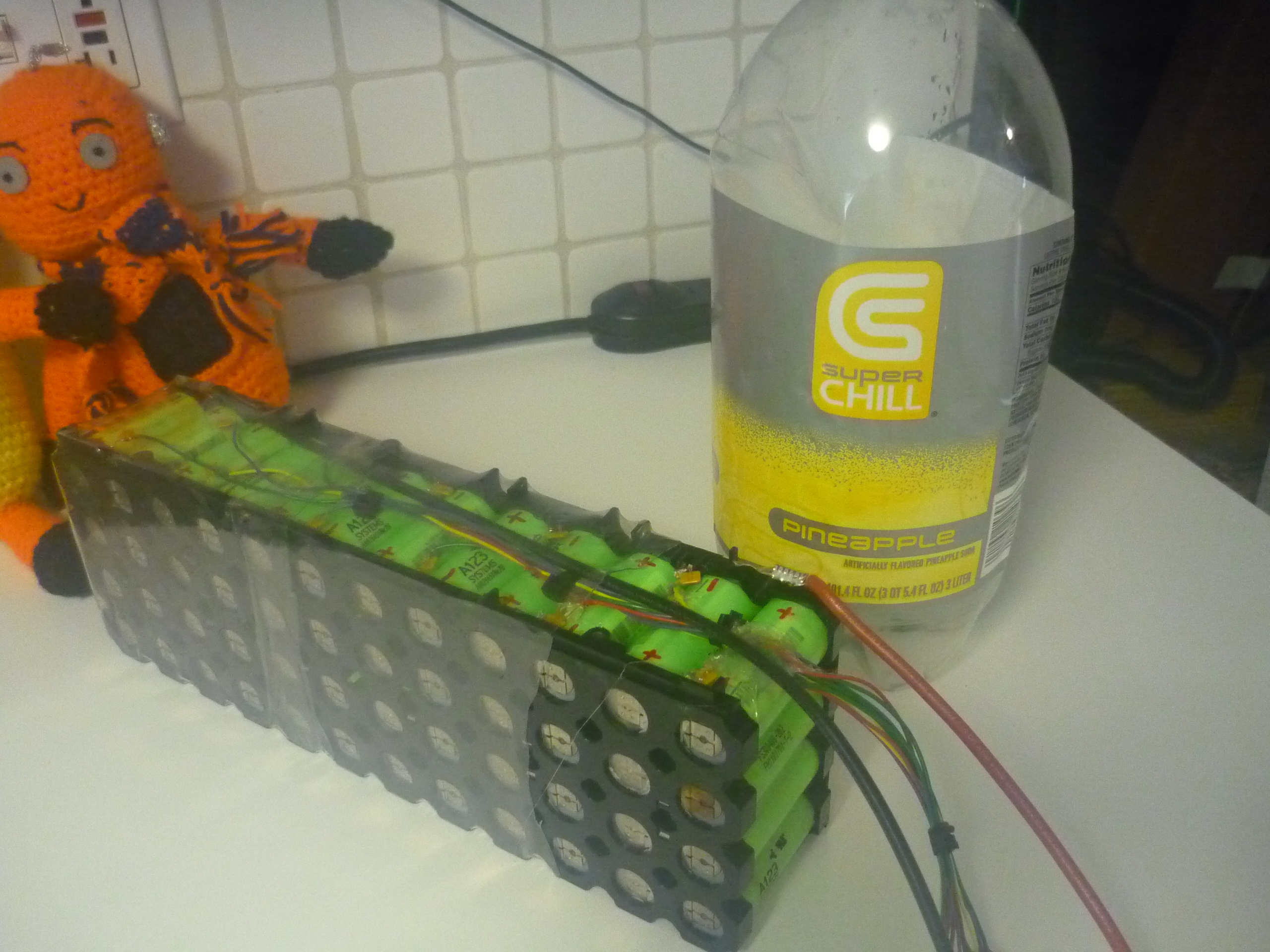
| The bottle-parts are slid over the cell group. I attached the two sides first and then the center tube on last to seal the module. The PET is surprisingly durable yet thin, excellent for shoving inside the scooter battery bay. | 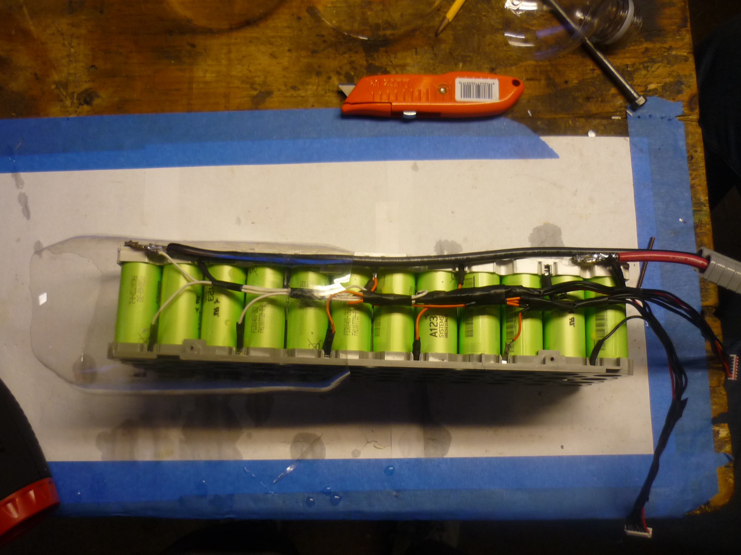 |
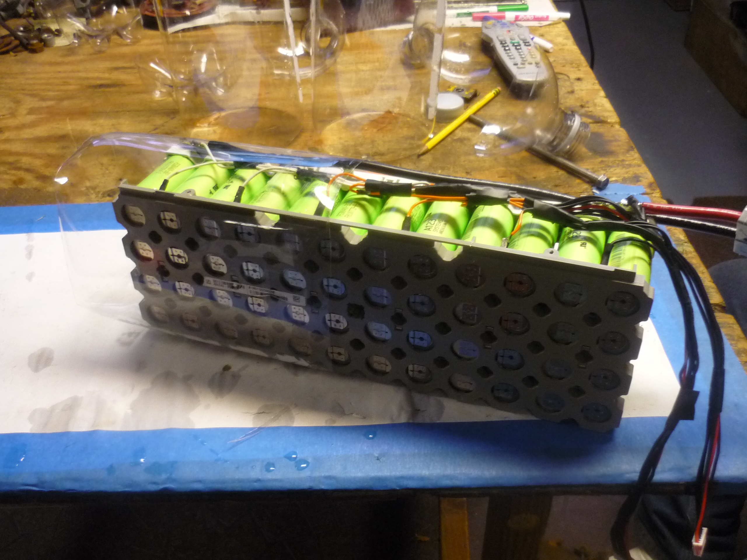 |
| After a bit more heat-gun action, the module is sealed up in PET plastic, providing a durable boundary between the cells and the scooter shell. | 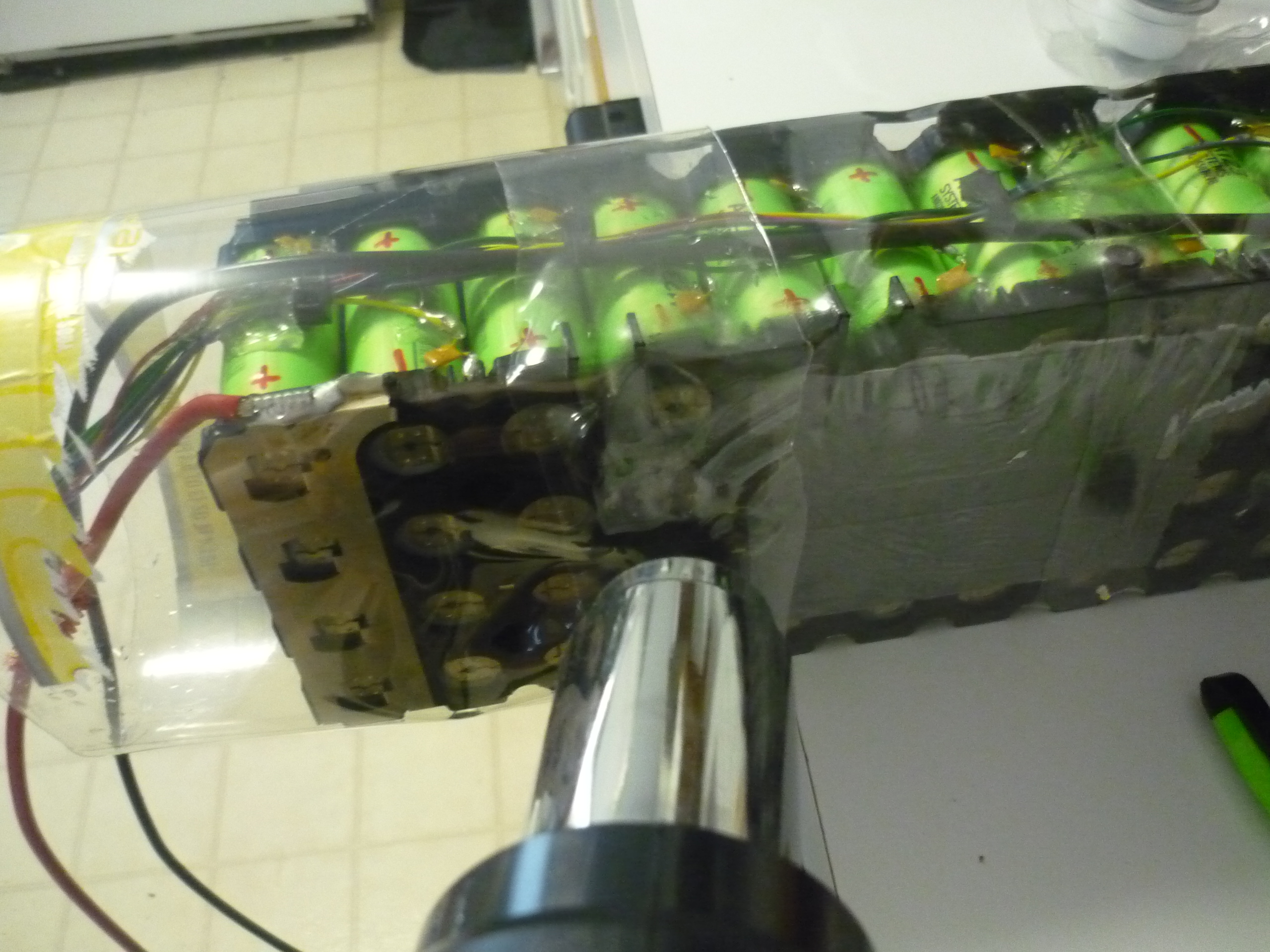 |
 |
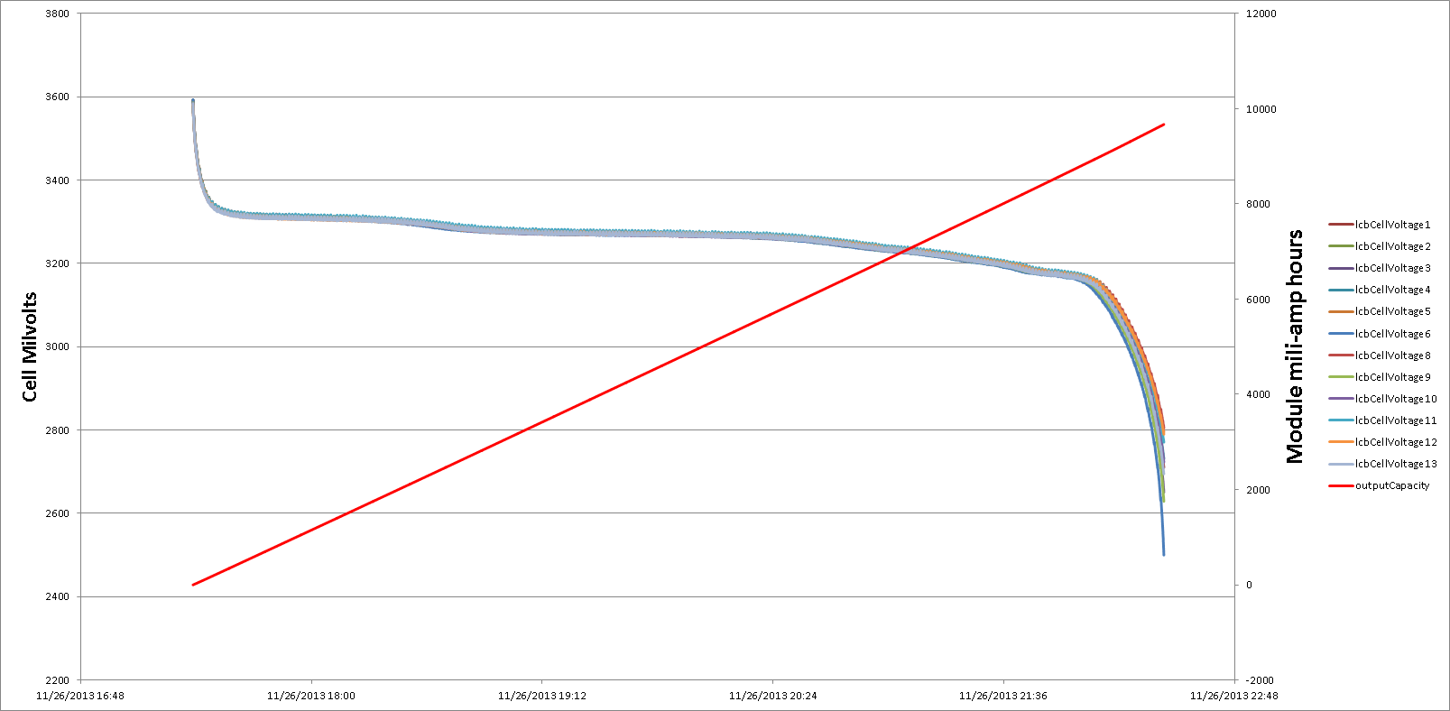
The Battery Module: Capacity Testing
| What |
Data Image |
| Module 01: Dataset [xlsx] [txt] Capacity: 8.24 Ampere-hours There was an issue with this scrapped module, apparently, the lower 6 cells had been held at a low voltage for an extended period of time. This 'plating' results in dissolution and permanent lost capacity. An identical module (shown below) is over 1.4 Ampere-hours greater in capacity. This effect does not go away with cycling. |
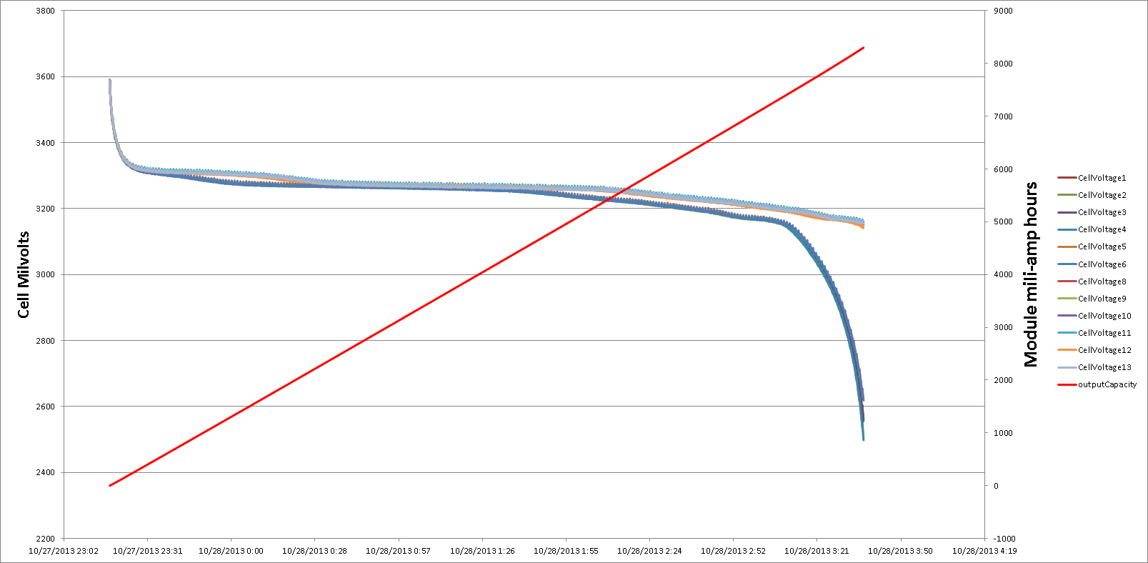 |
| Module 02: Dataset [xlsx] [txt] Capacity: 9.67 Ampere Hours This is the same style scrapped module, that has not been held at a low voltage. Each of the cell groups appear to have a near-identical capacity. Note both of these tests were preformed on a Hyperion 1420i charger. I highly reccomend it. I made a case for mine, and you can see it here: |
 |
Fitting Everything Together
| What |
||
| To attach the battery module in a removable fashion, I opted for Velcro straps, and small slip through rings, made of bicycle spokes, welded to the scooter hull. Shown far right is the module held in place inside the hull. | 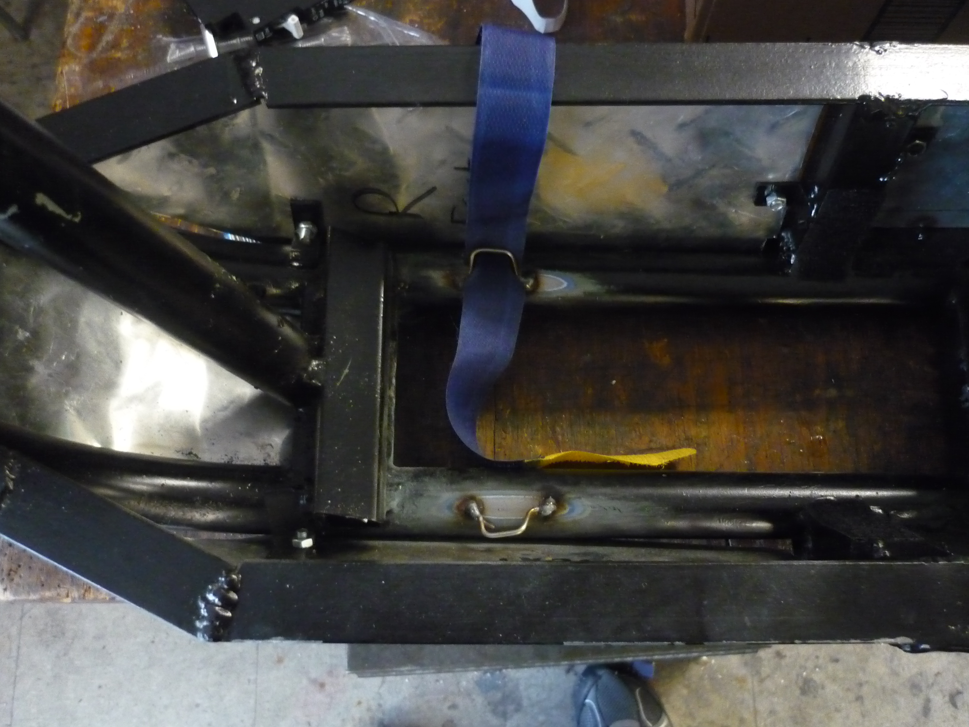 |
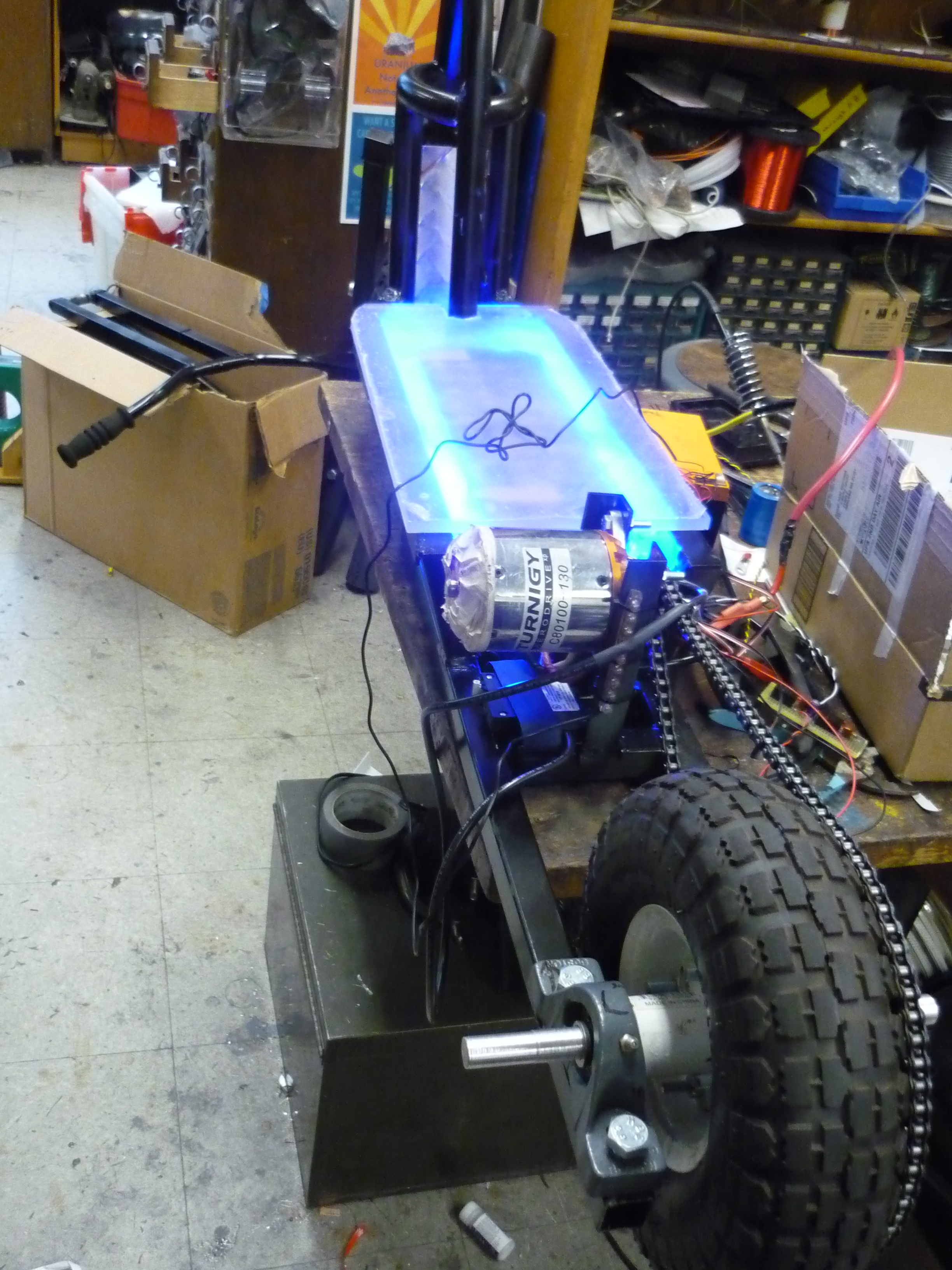
 |
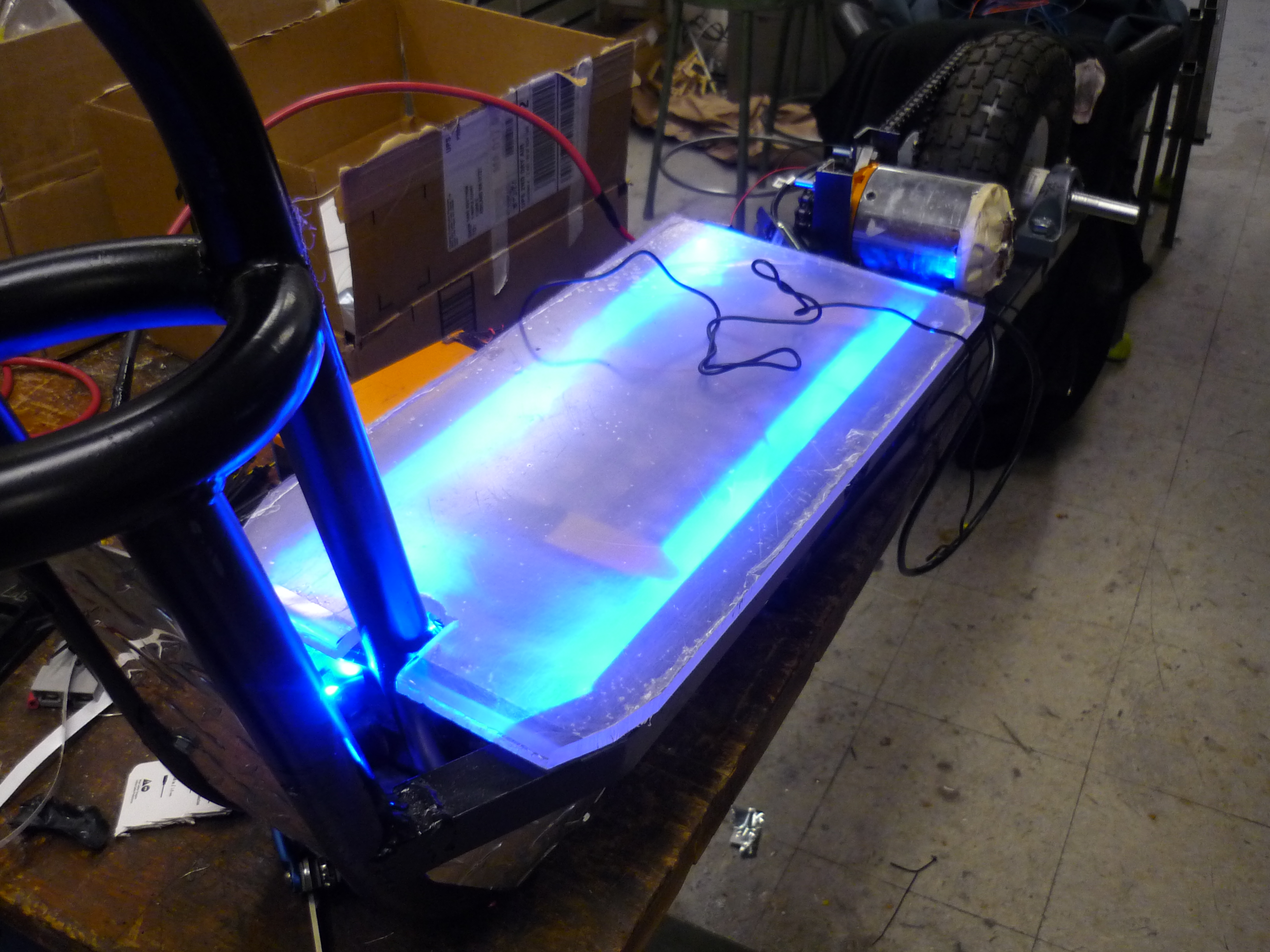
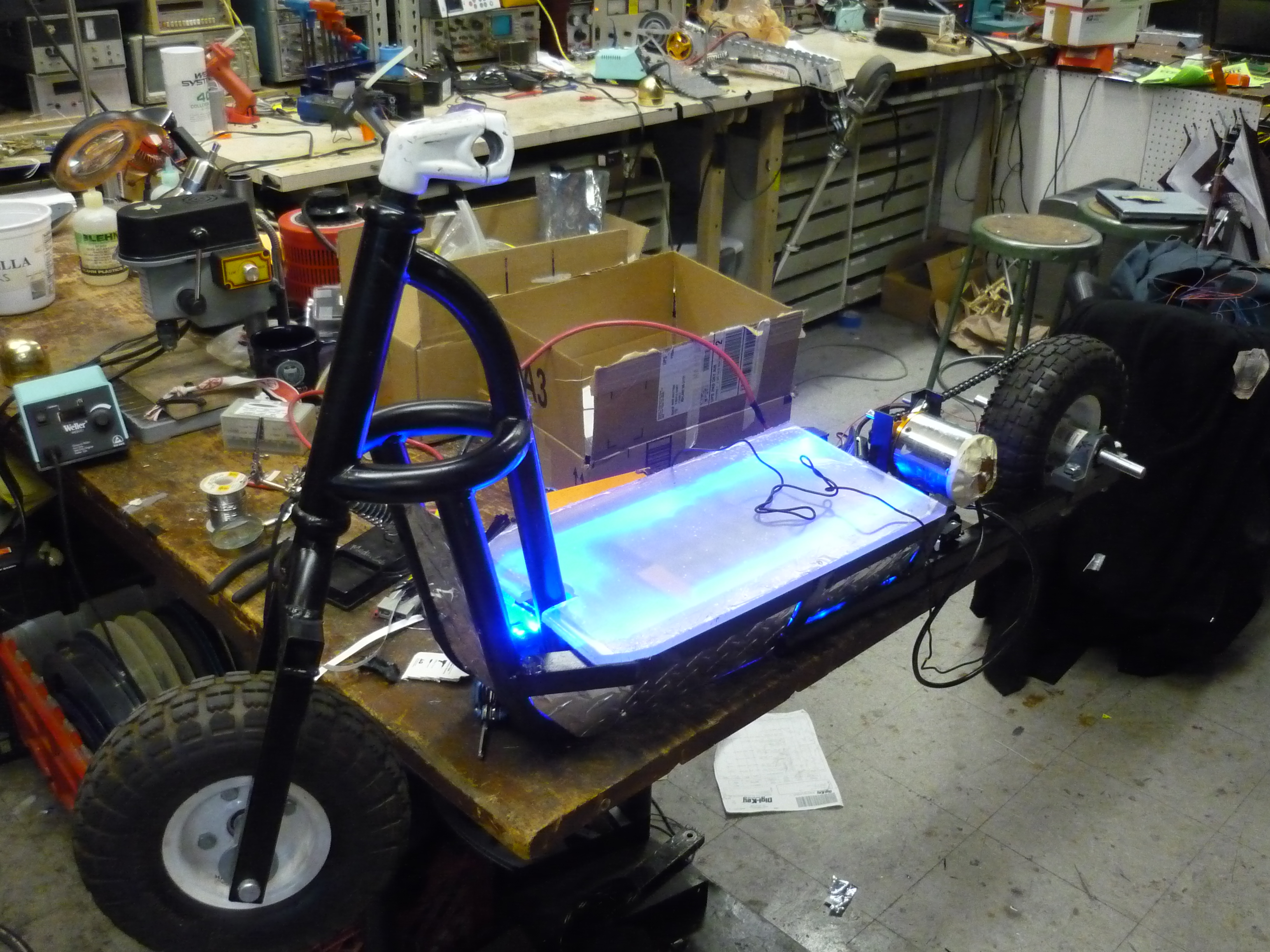
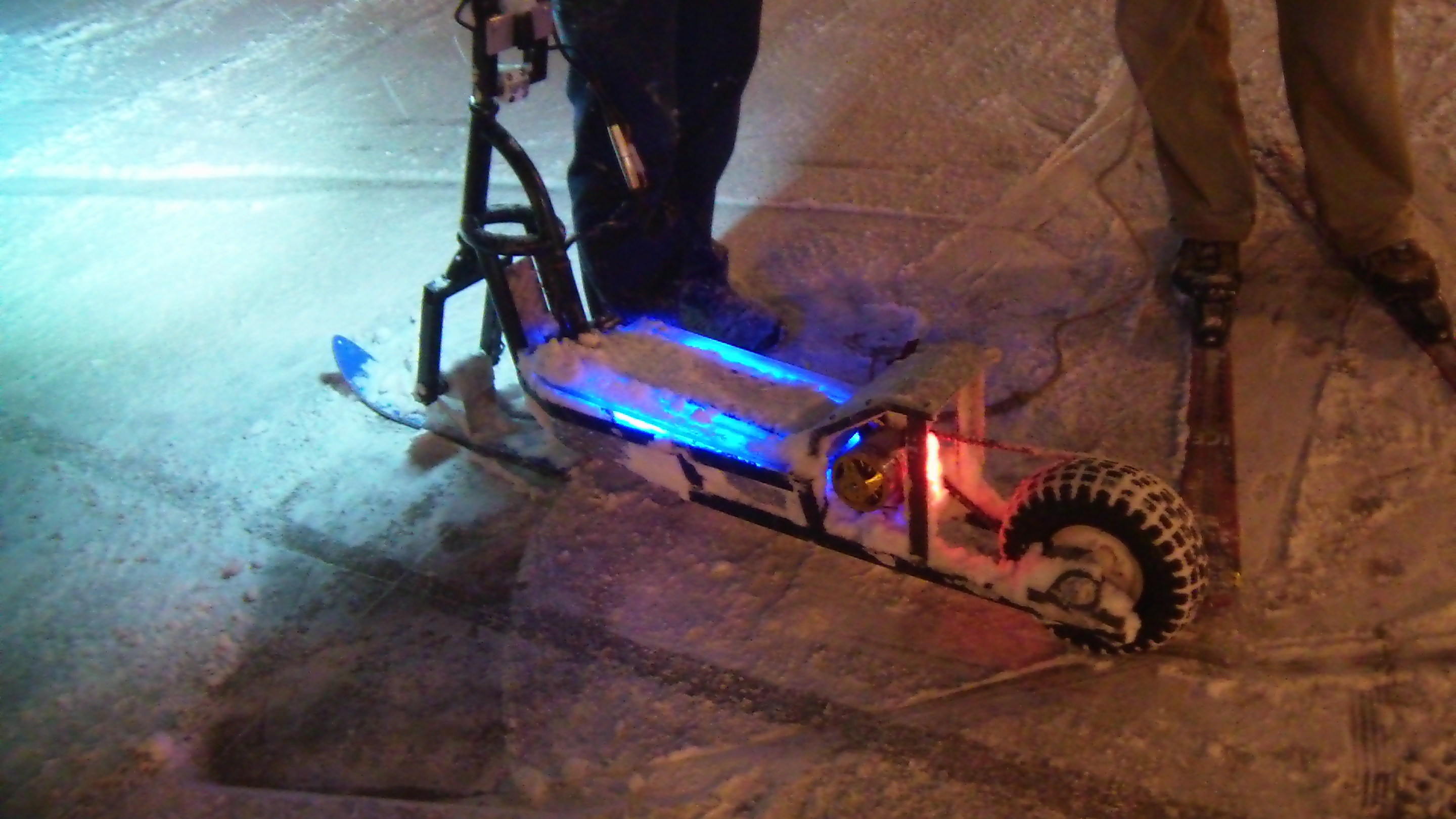
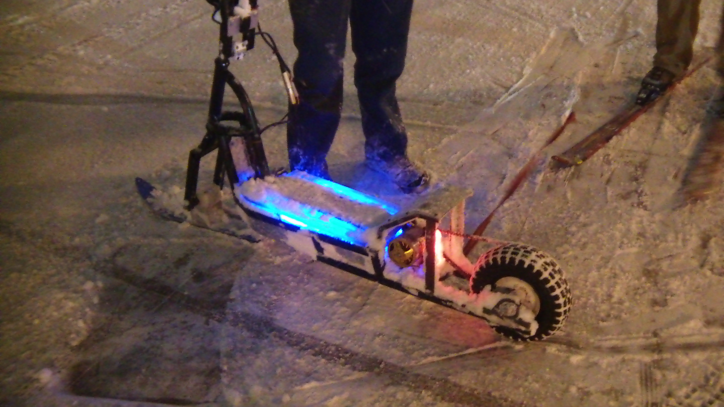
| Under/over glow I used led strip light inside the hull, namely to get a neat back-lit effect when riding at night. The led strips run from the 12v dc/dc converter and are on whenever the scooter is powered up. Its a decent indicator during the day and pretty excellent in the evenings. |
 |
|
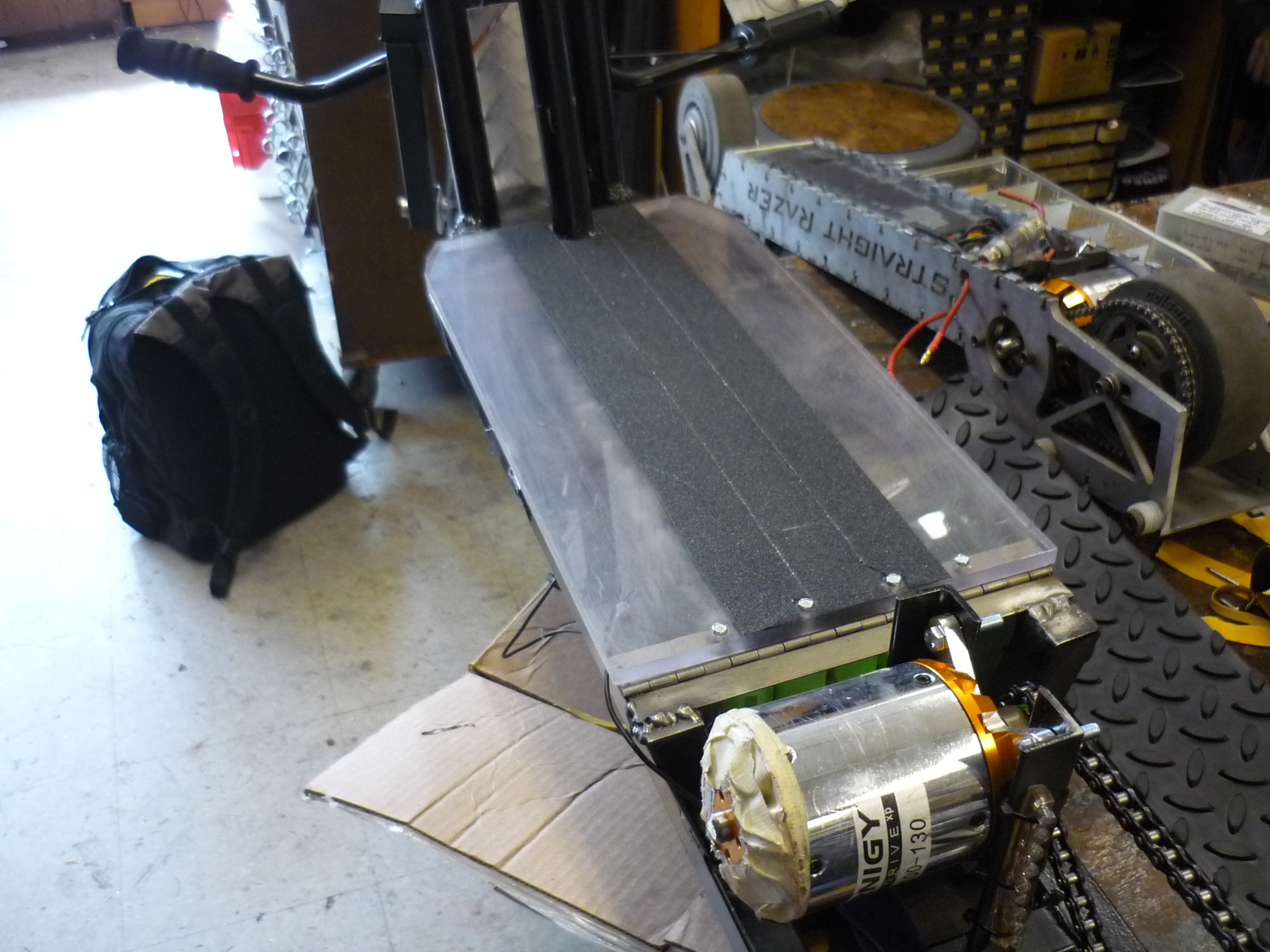
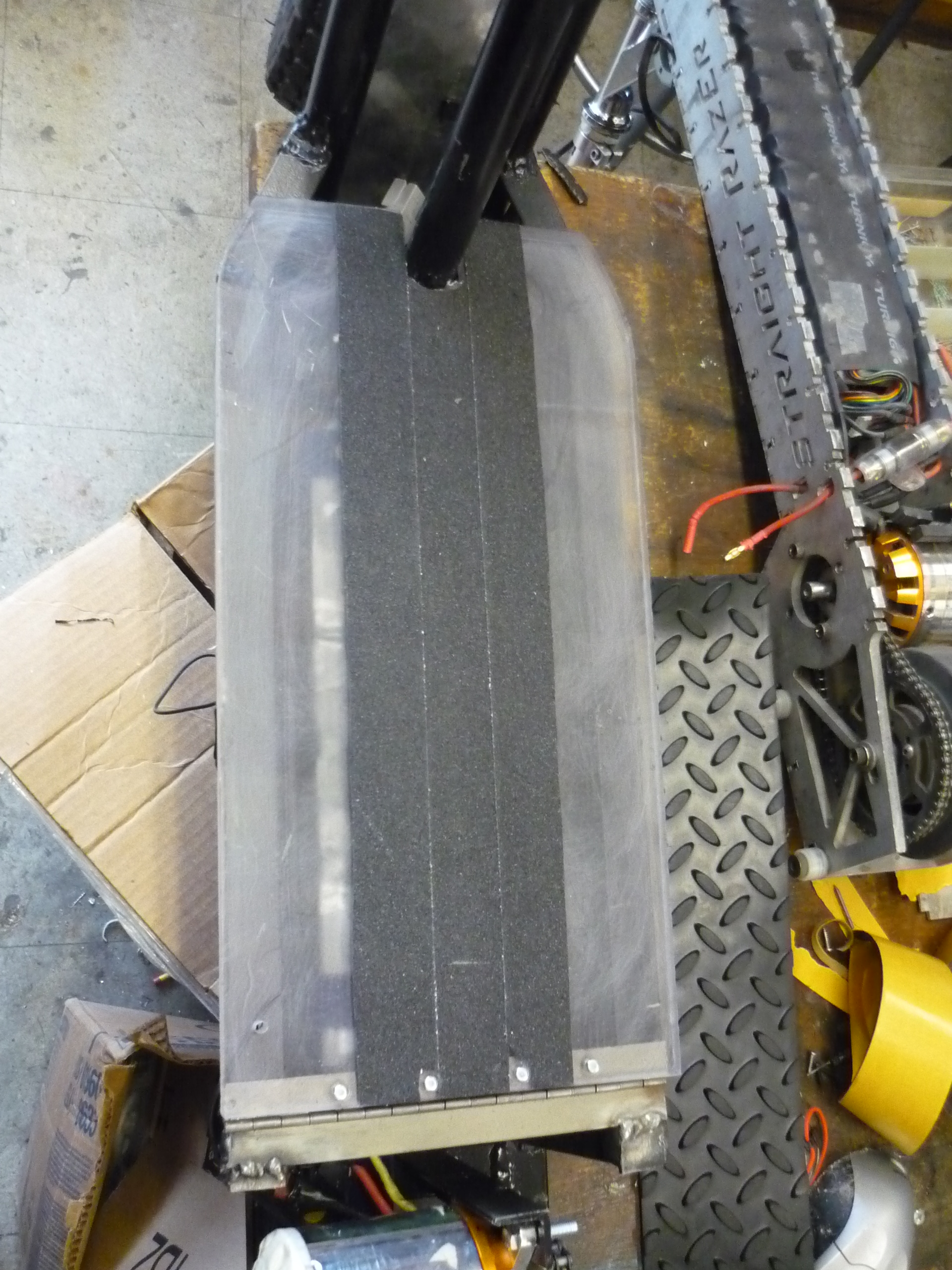
| Adding
Grip-tape and tying the hull together I toyed with a few types of grip, and ended up deciding on using something similar to this [link] shown later on in the build. Note the Charles-guan straight-razor sitting next door [link] |
 |
 |
| Adding
some extra 'grip' during snow-scooter expedition it became fairly apparent that the back aluminum cover was fairly slick. Fortunately scrap grip-tape appeared from another project, [From Noel Hwang]. It was a bit tworn up but works fairly well. |
 |
 |
Snow-Mode
| What? |
||
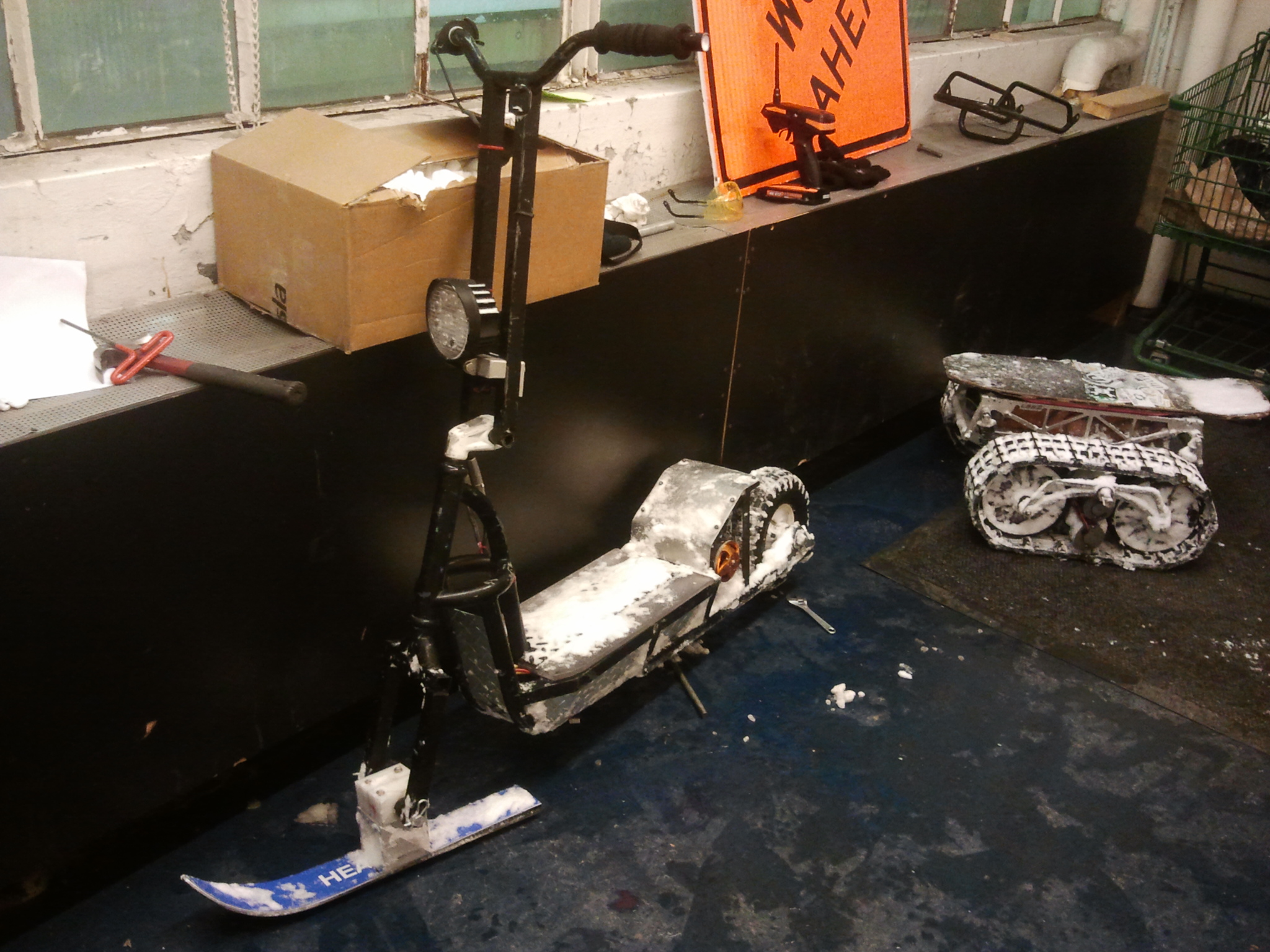
| Beginnings This add on is actually pretty interesting. The ski was aquired from the MIT swapfest over the summer, thanks to the glorious kirkby. The adapter was quickly fabricated by the mecchie-ninja that is known as Ben. Suprising as it sounds, my scooter shares an identical axle size to the ginormous ben-scooter. This assembly actually fits both scooters. With two shaft-collars and a bit of elbow grease its a drop in replacement for the front wheel. |
 |
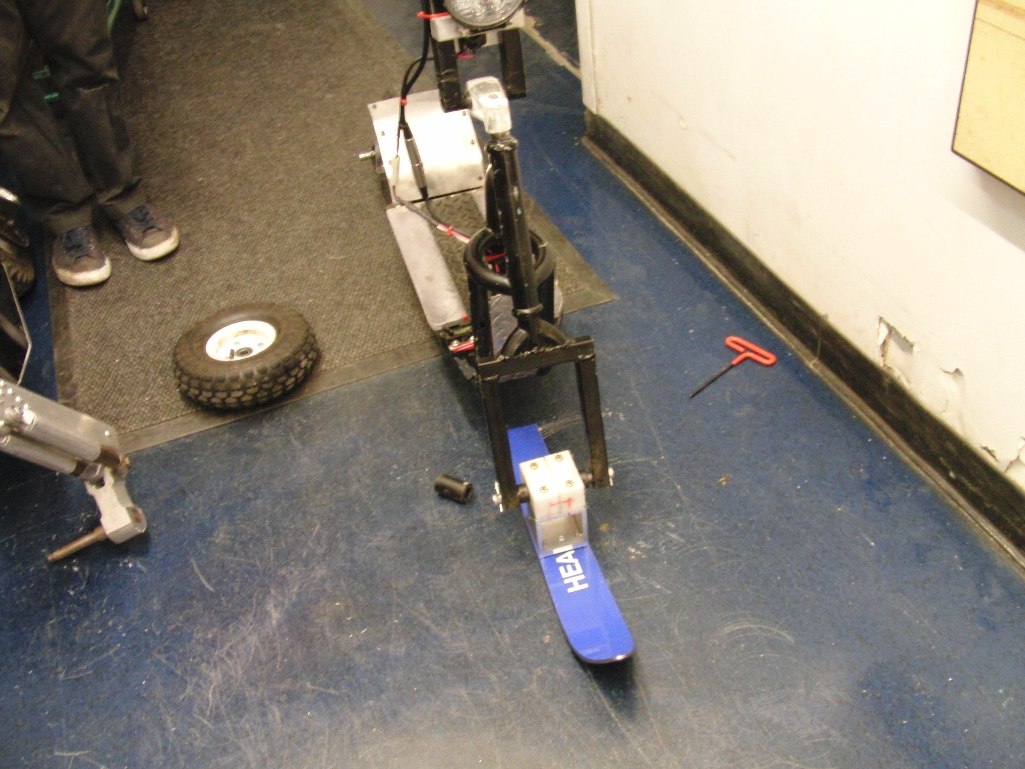 |
| Hold
on, I want to see that in full view. So thats what a rear-wheel driven front-wheel ski scooter looks like. In icy conditions the lack of brakes doesnt make a large difference! Steering and pivoting of the front wheel still work well. The pivoting linkage is UHMW, which is excellent, as its slippery and smooth for that pivot point. |
 |
 |
Bill of Materials
| What |
# used | cost ea. | cost total |
| Rear Wheel Ball Bearing + pillow block | 2 | 28.12 | 56.24 |
| Front & Rear Wheel | 2 | 5.99 | 11.98 |
| 3L soda bottles | 3 | 0.99 | 2.97 |
| Twist throttle assembly | 1 | 18.00 | 18.00 |
| misc. steel angle iron | A lot | 0 | 0 |
| Initial Scooter Frame | 1 | 10 | 10 |
| 'Mellon' 3 phase motor | 1 | 1 | 89 |
| 120A ESC | 1 | 90 | 90 |
| Wheel sprocket | 1 | 12.00 | 6.95 |
| motor sprocket | 1 | 4.83 | 4.83 |
| #35 chain | 1 | 3.00 | 3.00 |
| LED light assembly | 1 | 19.20 | 19.20 |
| 50w dc/dc (40v -> 12v) | 1 | 18.26 | 11.26 |
| Sealed IP65 switch | 1 | 8.22 | 6.22 |
| 120A circuit breaker | 1 | 25.05 | 25.05 |
| Total | ~ $360 |
| Outdoors Testing |
|
This was a test at the Ashland State Park, driving in from the parking lot out to some of the further trails, note that the MK-1 scooter has no active suspension system and the shock & vibrations were very, very apparent. A lack of mechanical brakes, coupled with the very 'perky' throttle response made the ride almost unmanageable. [HD file] |
|
This was a test ride after I was kicked out of Caulmsett state park, along the Long Island sound. Unfortunatley the fairly large amount of cold wind resulted in the audio sounding like a winter-blizzard, so background music was dubbed over. It is a beautiful area, now only if I was able to ride in the park without being chased down by maintance crews... [HD file] |
|
This was a test ride in the
snowy semi-plowed streets of cambridge, using the SNOWFORK adapter. A front ski-attachment was quickly crafted during the hours after meeters. Both myself and Build-It-Ben, realized that we had the same front wheel shaft diameter and before anyone could realize it a SNOWFORK adapter was born. Thanks again to Nick for the ski! [HD file] |
| Interesting Photos while scootering | |
 |
 |
 |
 |
 |
(There's
other photos in the photo
gallery)
Concluding
Remarks:Stand on the shoulders of comrades.There's quite a lot of info out there on crafting up your own electric scooter-contraption. If you do not feel comfortable cad-ing and designing up front, incremental design (shown above) works too!
As a place to start, take a gander at Charles Guan's epic instructable [link], Shane Colton's pile of information [link], Ben's monster scooter build [link], and DGONZ's very nifty cruz scooter [link]. It may seem a bit pricey to build a scooter, but consider that this is almost completley overkill, filled with a motor that is more appropriate for an ATV, and a drive train that would work well on a dragster. A DC brush drivetrain and lead acid batteries can be made to work as well, for quite a bit cheaper. There are a pile of options out there, and this is just one of many. Do consider a design that is incrementally upgradeable, as you find things that need improvement, the ability to add/ subtract is excellent.
In terms of 'future upgrades':
* Consider adding in room for mechanical brakes.
This
is pretty crucial for having something that behaves well and
is manageable to use, it shouldnt be an after thought, it will
never just fit in neatly if you dont plan a little bit.
*
RC helicopter controllers should not be used on vehicles. Helicopter-style
control doesnt work well on the larger motors in vehicle applications,
due to the nature of their design, and lack of current-control, it
makes operating this vehicle very difficult and fairly dangerous.
* Suspension would be
niceThe
ability to absorb some of the bumps and brusies, either on the horribly
maintained roads or off-road, would be a neat feature.
If you have questions or comments, ask below or send over an email.
| Comments: |
|
HTML Comment Box
is loading comments...
|
(be
careful, im not responsible for your new UV tan from mig-welding
everything ever)
Dane.Kouttron
Rensselaer Polytechnic Institute
Electrical & Electrical Power
631.978.1650
