Dane.Kouttron
[10.04.13] SCARA 3D Printer Upgrade 01 [Resolution & Repeatability]
| What?
Preform upgrades to the 3D printer SCARA robot project to allow for speedier, higher resolution printing, with a more repeatable output |
 |
 |
 |
| This
project is a detailed walk through of recent adventures in attempting
to
crank-up the resolution,
repeatability and mean time between failure (MTBF) on the SCARA Robot
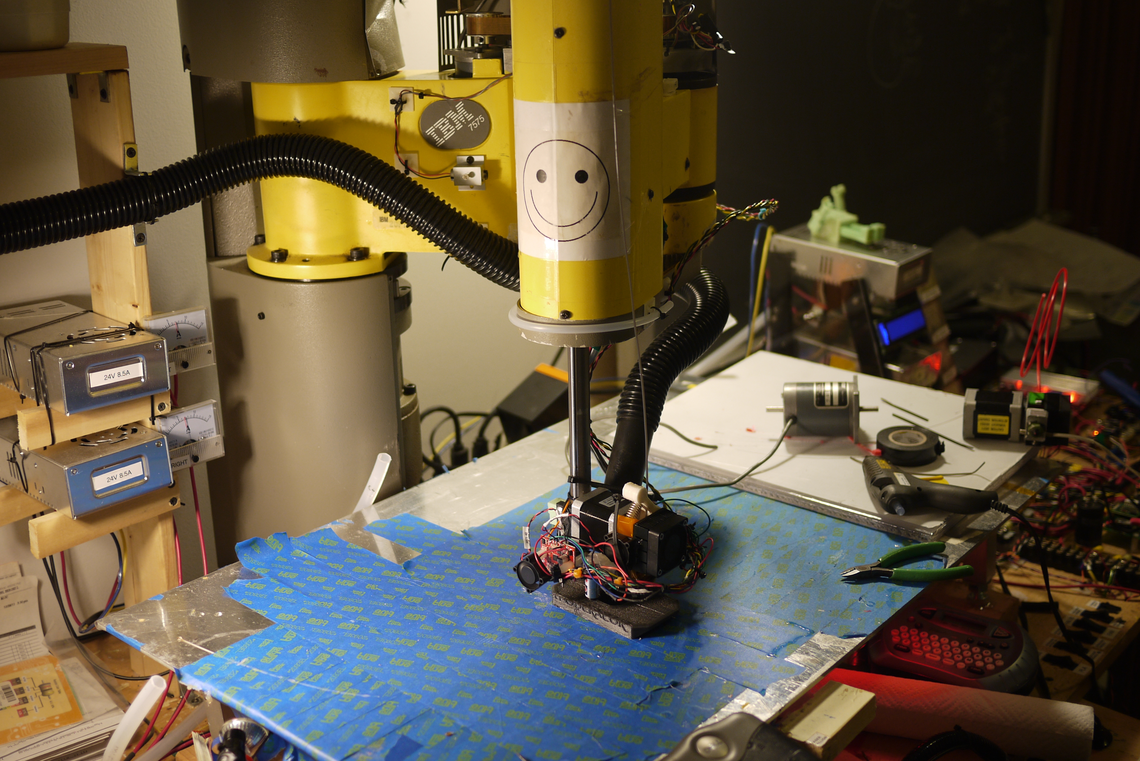
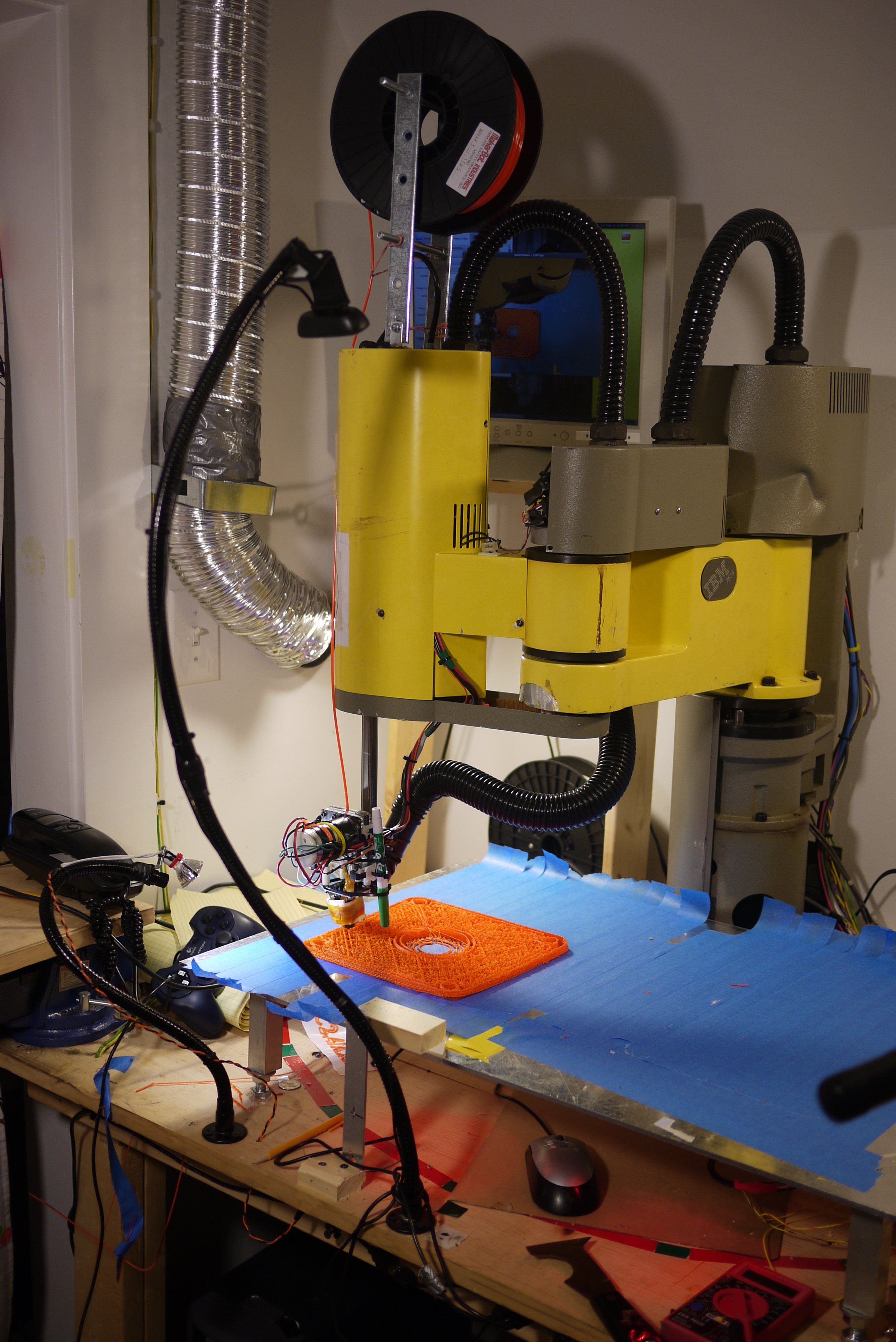
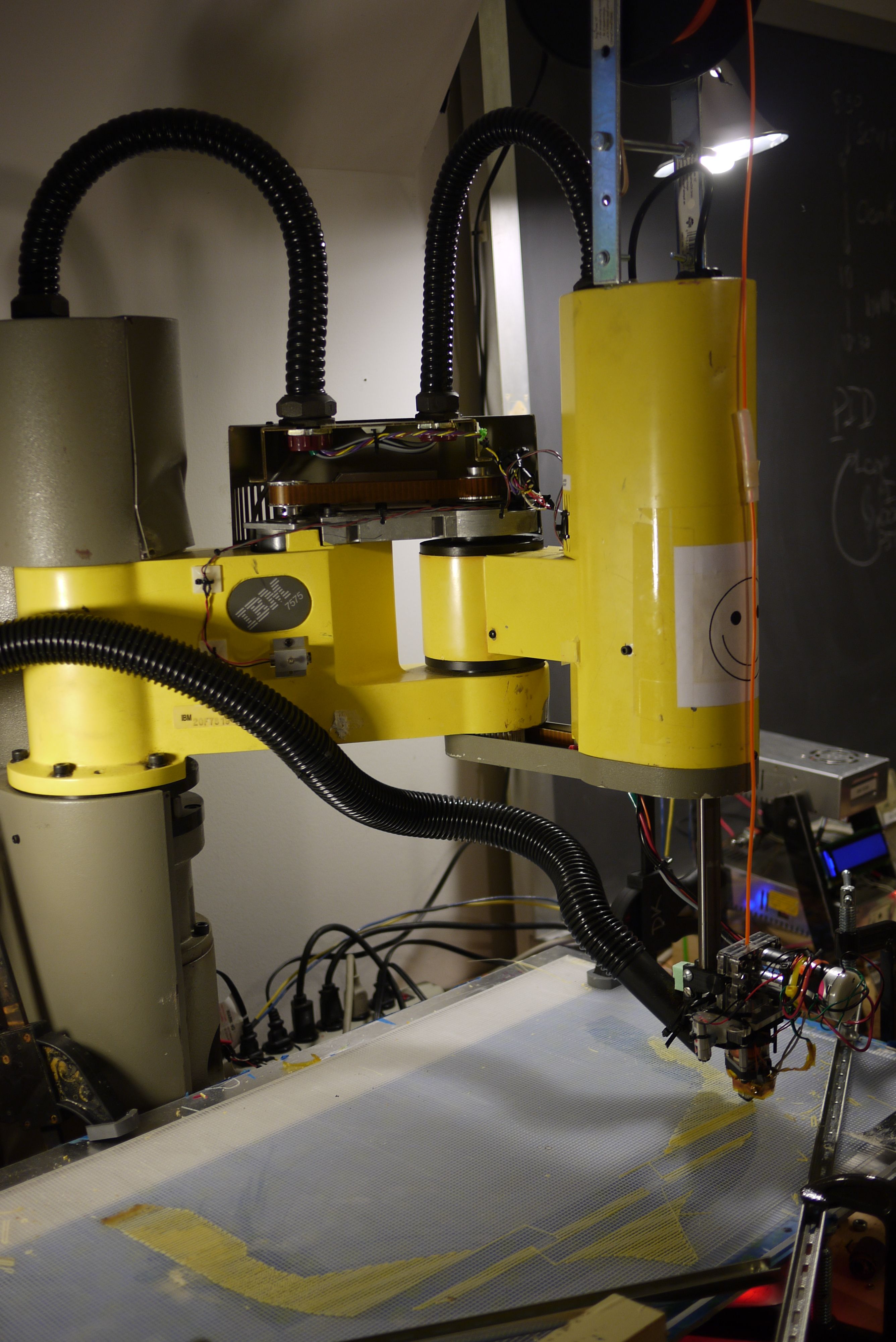
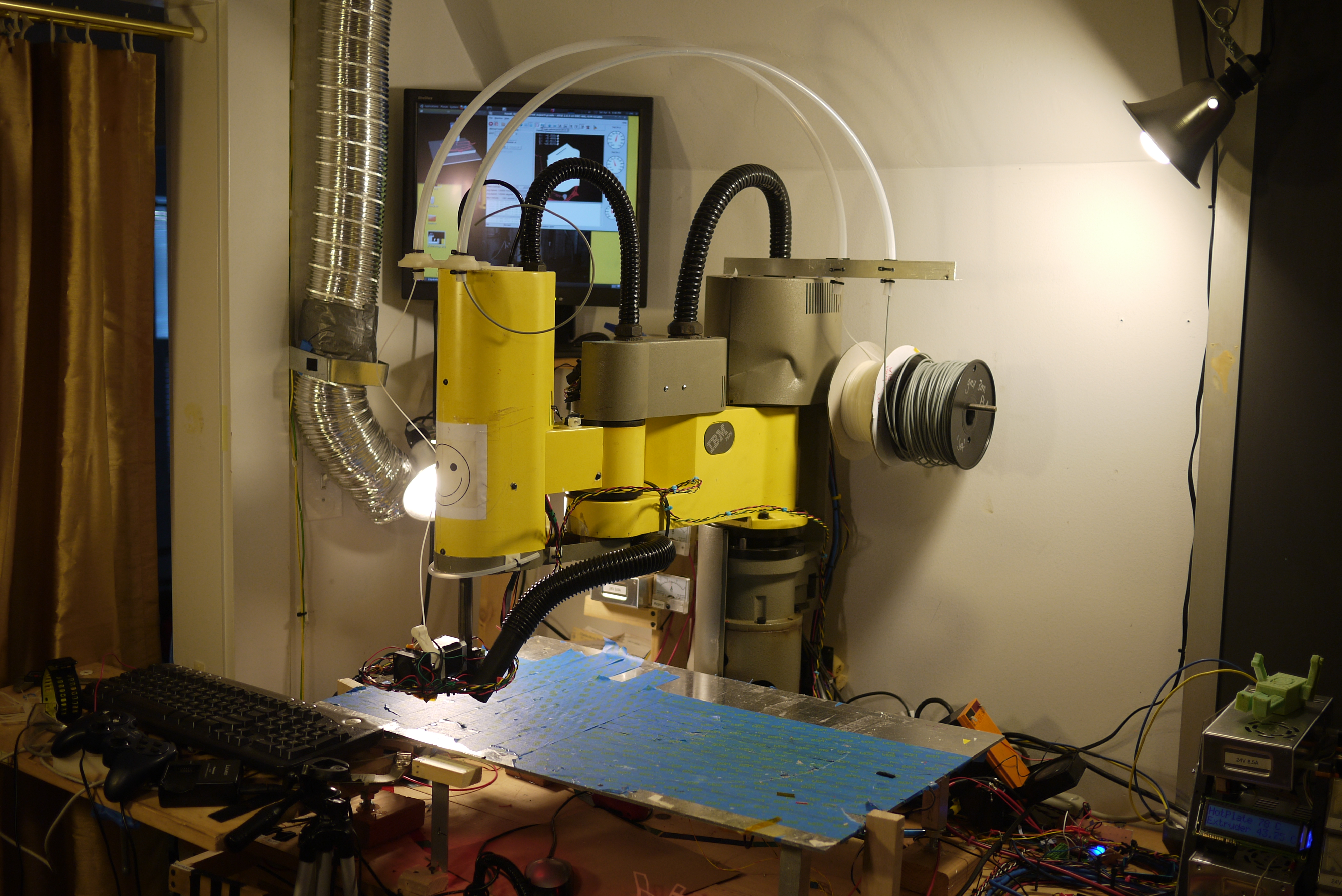
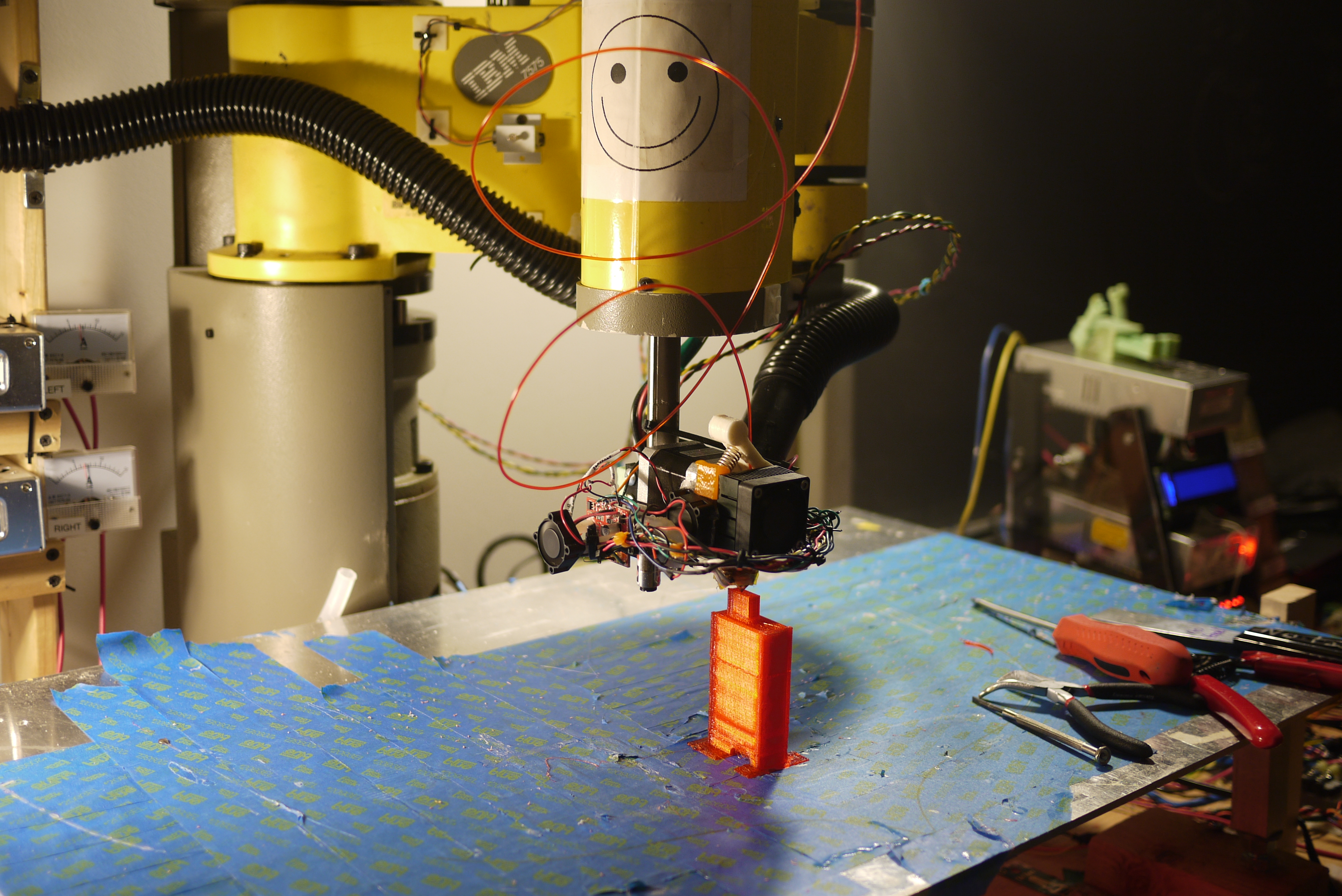
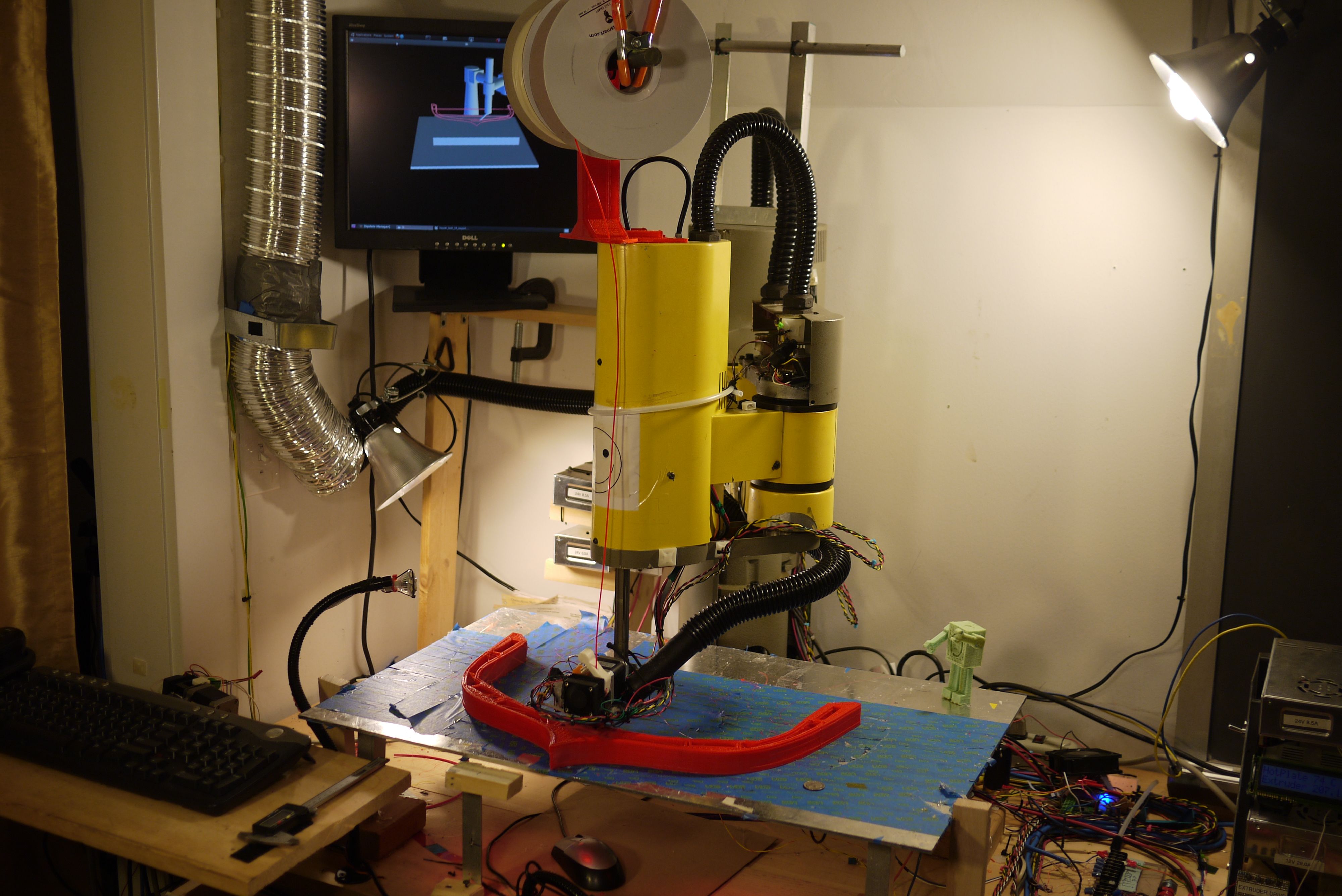
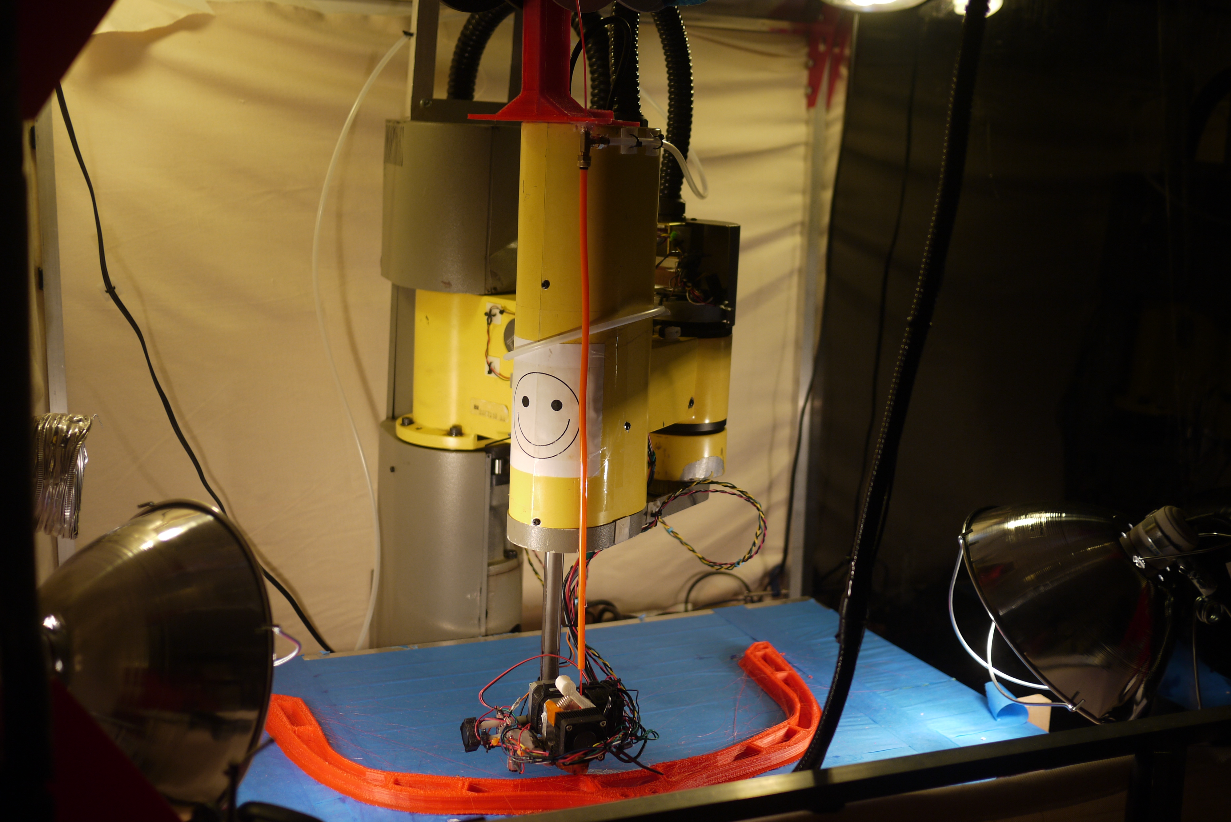
Arm 3D Printer (of science). Robot mechanicals are based around a
'rescued' 184lb
IBM 7575 scara robot
(circa 1986) that was scavenged from a lab clean out. The lofty goal of
this project is to fix some
outstanding issues and document progress. The modifications detailed
below range from optimizing extruder topology for operation in a heated
environment, management of a heated environment, slicing optimization
for large format prints and full EMC2 real-time integration. The huge
reach of the IBM 7575, allows for printing large objects, (roughly
~25″x16″x8″ maximum). Note the initial documentation is detailed here [link]. Have a read before running through the updates. |
| What? |
Extruders | Filament Feed | Heated Build Chamber | Lighting and More Heat | Chilled Filament | Updated Prints | Conclusion | Image Directory |
| Video of upgrades | Footage |
| Looking for some non-warpy ABS
plastic prints, a large robot from the 80's and a giant heated
terrarium? The following is
a demo video of the IBM 7575 robot-arm-abs-printer tackling some of the
relativley large 3d Prints shown below. HD video: Link Soundtrack: The Seatbelts-TANK |
Extruders: Trials, Tribulations and Upgrades
| Details | Image / Media | Image / Media |
| Retiring
the Makerbot MK5 DC 3mm extruder The robot started running a makerbot MK5 extrusion head. This was fantastic for early development, it was simple, I ran the DC motor from my theta-0 drive controller, and the motor control was tied to a gpio pin on the control computer parallel port. Unfortunately, after many hours of printing, the extrusion head finally failed. It appears that a clog or buildup of charred garbage occurred within the extrusion head, causing a blockage. The blockage prevented the inbound ABS from going anywhere, while the DC gear motor + MK5 gear head continued to provide an immense amount of force, which eventually pulled the tapped holes on the heater-block right out. This pulled the 1/4-20 taps right out of the heater block, making it fairly difficult to swap / repair. It had served 1.5 yrs of faithful service, and needed to be reborn to pump plastic and polyphonic tones with steppers motors. |
 |
 |
| Lulzbot extruder ahoy After hearing excellent fanfare about the lulzbot extrusion head, (and the fact that they run 3mm abs, somewhat of a rarity at the present time), I saved up and splurged ~100$ for a heated, fancy extrusion head. For the sake of time, I swapped out their thermistor for the one I had been running on my machine and quickly bolted it onto the DC gear motor assembly and kept pushing plastic, sporadically, for roughly 2 months. |
 |
 |
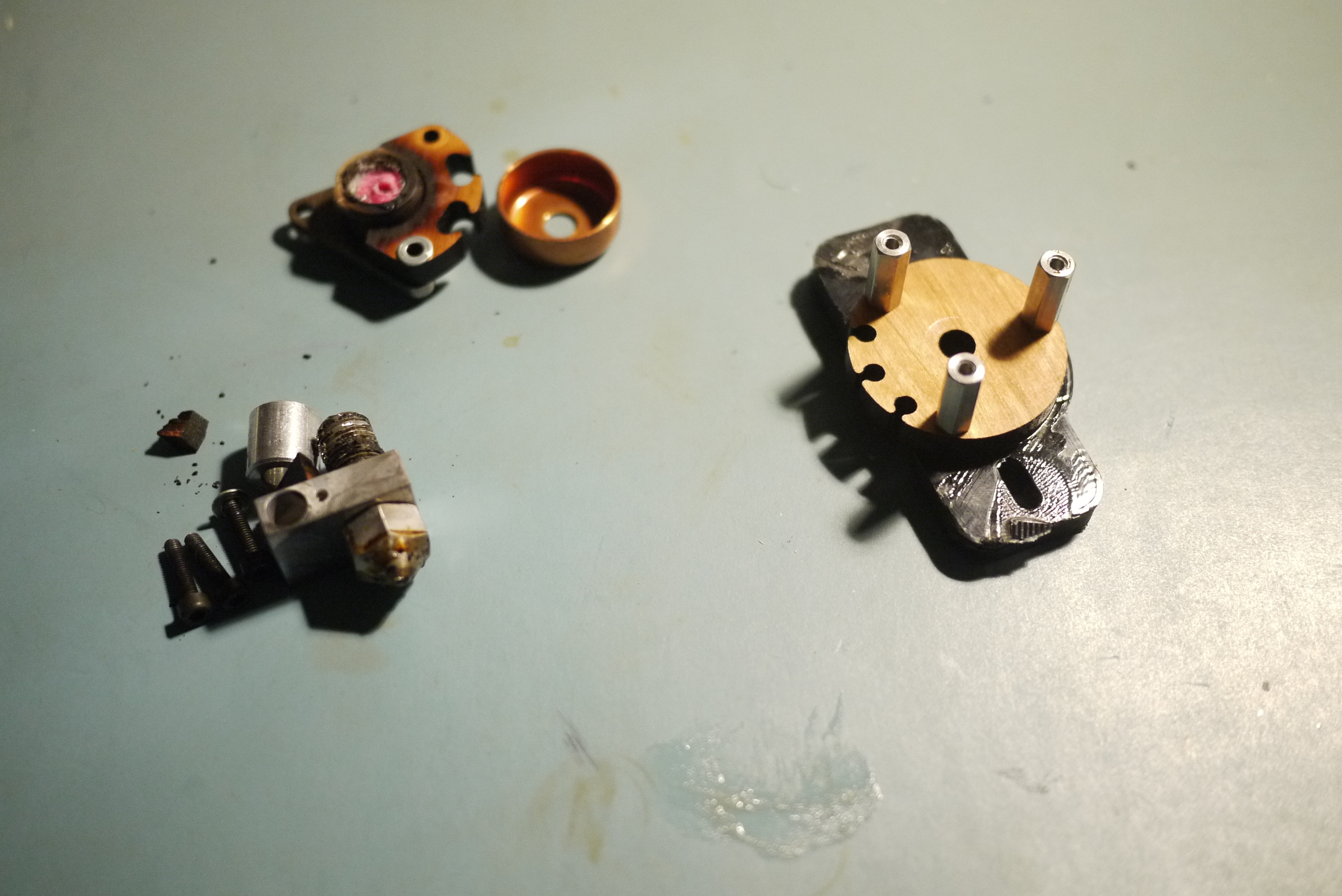
| A
Charred Lulzbot extruder Underneath that pile of charred extruder is what once was the lulzbot extruder. After printing a number of canoe prototypes, something happened. The MDF parts on the lulzbot extruder ended up failing, either due to thermistor issue (I am still doubtful of this) or possibly my heater drive going wonky. Lulzbot did a tear down and came to the conclusion that I had to have been running it outside the temperature specifications and was ineligible for refund. Ah well, onto different topologies. |
 |
 |
| Stock QU-BD I purchased a stock QU-BD extrusion head with the stock stepper and attempted to 'just start printing', it was a bit finicky, so I looked around for tweaks and tricks to get the extruder to play in a more reliable manner. |
 |
 |
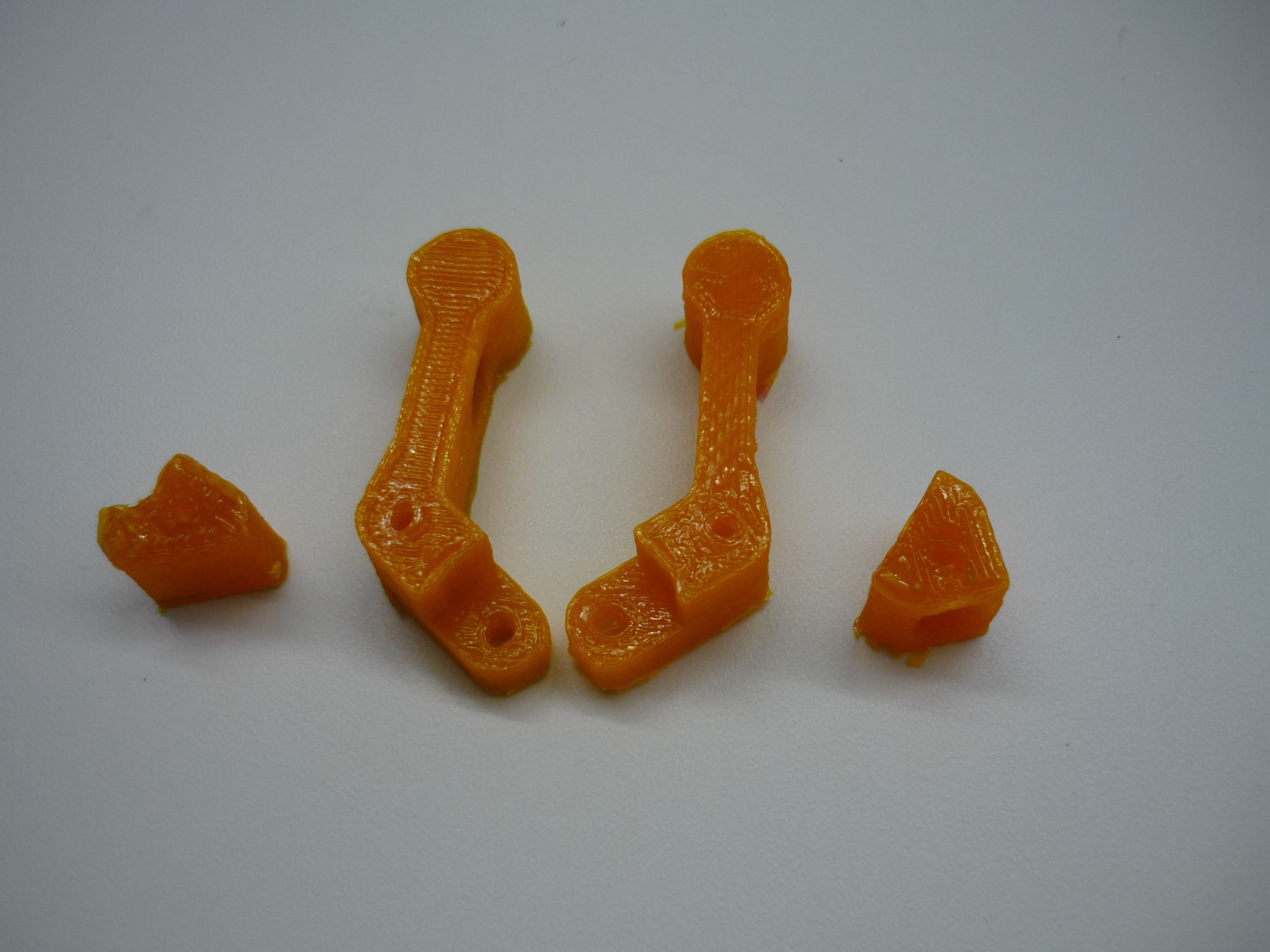
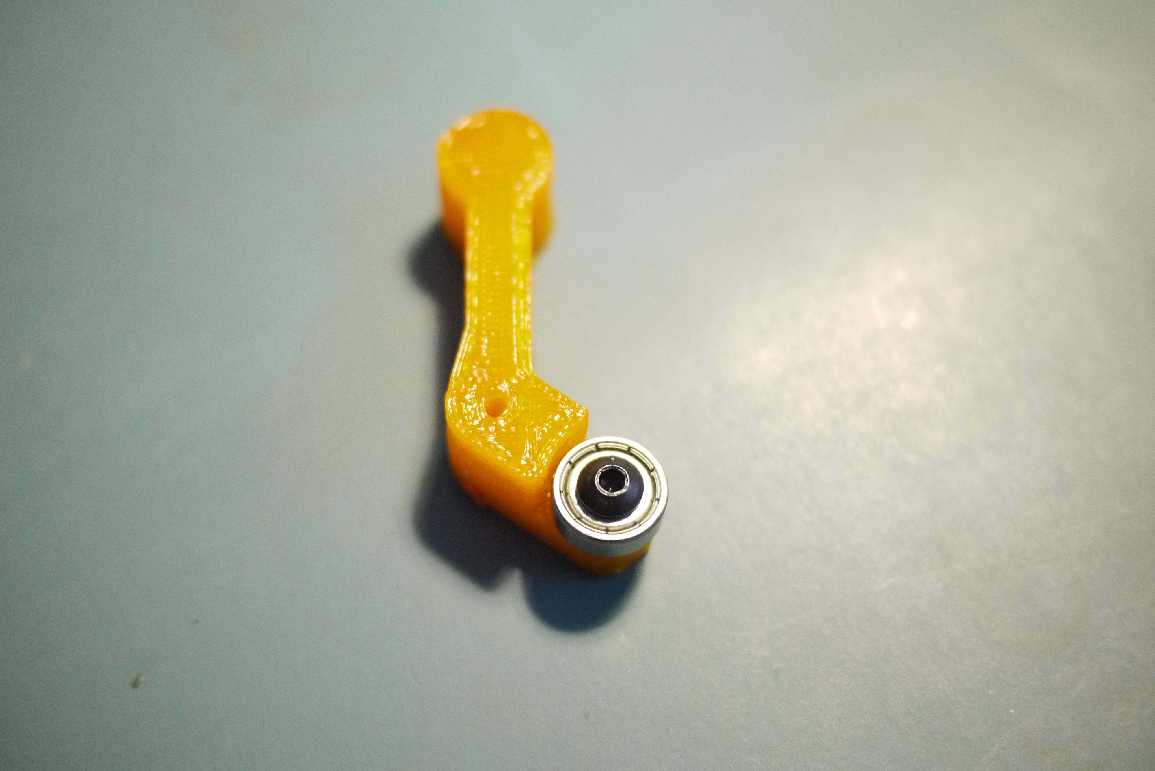
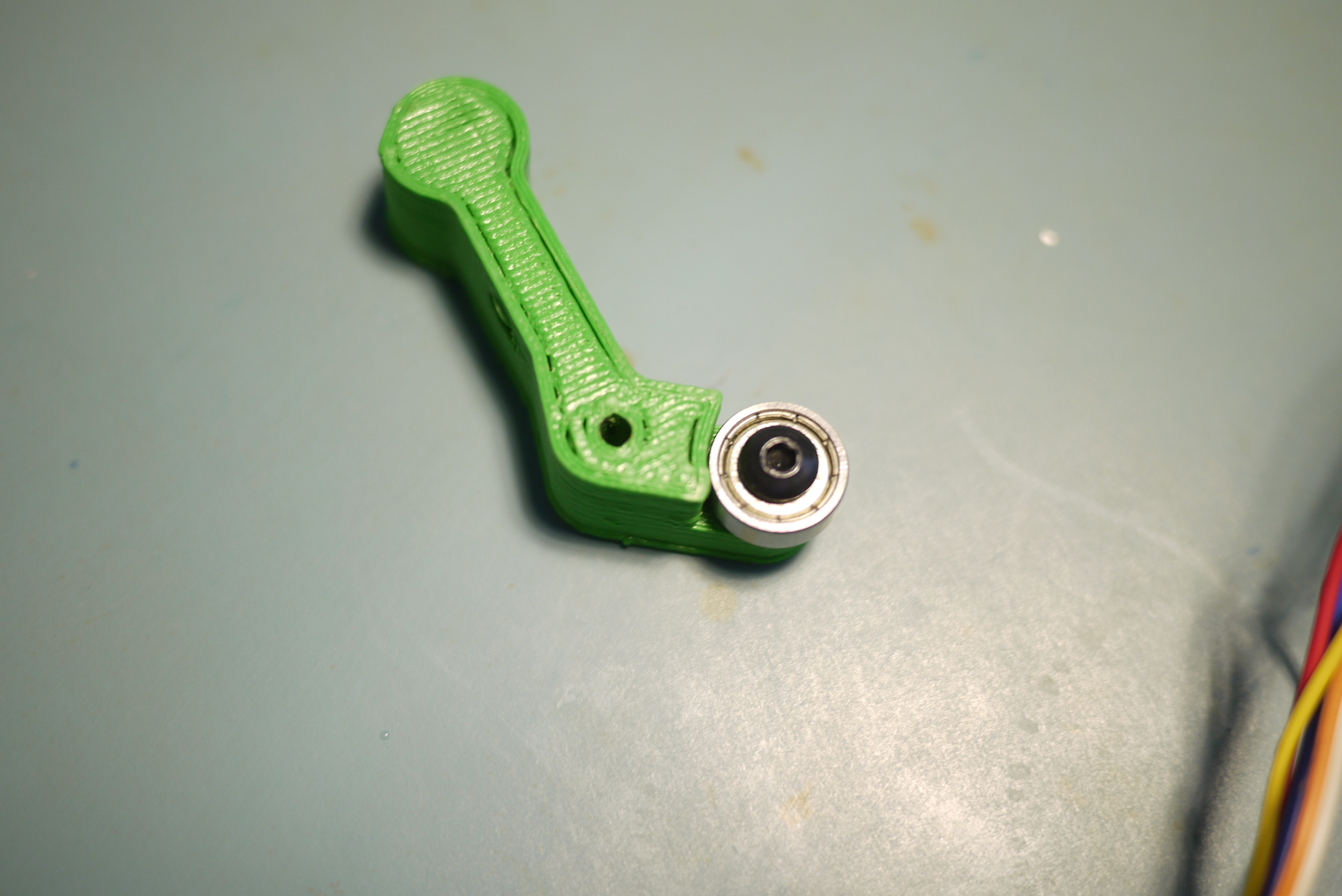
| 1.75mm QU-BD Modifications The parts shown are prints from the spring-loaded lever arm detailed here. Its an excellent set of instructions. I printed the parts using a gen 3 solidoodle, using 1.75mm orange PLA. The 4x13x5 bearings are from amazon [link], and fit like a glove. The screws are also from amazon [link]. I used a tiny washer from a harbor-freight kit of bolts, nuts and washers. The amount that the assembly is tightened is fairly critical. I tightened it to a point where it spun freely but didn't have any flex, then super-glued the threads to the PLA lever arm |
 |
 |
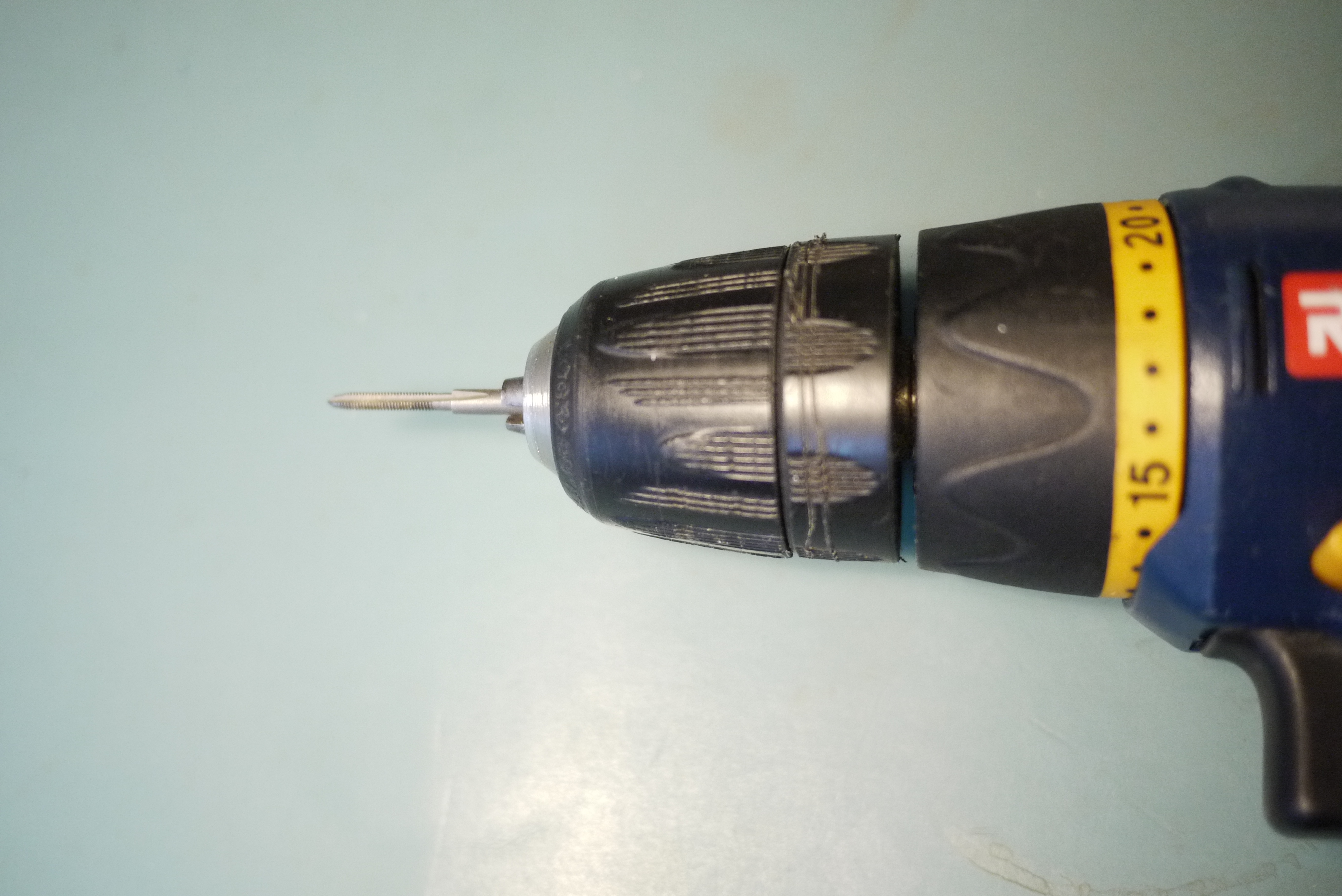
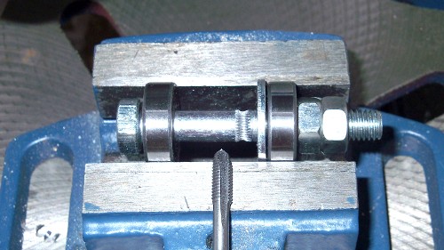
| 1.75mm
QU-BD Modifications part 2 Using a portable drill and an M3 tap, i 'hobbed' the QU-BD extrusion gear. This process is documented [here]. Its interesting, as it increases the contact surface area, and only requires minimal easy-to-do machining. |
 |
 |
| 1.75mm QU-BD Modifications part 3 After using the stock QU-BD extrusion gear, modified with 'hobbing', I was still getting re-curring jams. Either the extrusion head was 'chomping' too far into the thin 1.75mm plastic and loosing traction or something wasn't quite right. I managed to find an MK7 extrusion gear [here] and swapped it in. The difference was very noticeable. |
 |
 |
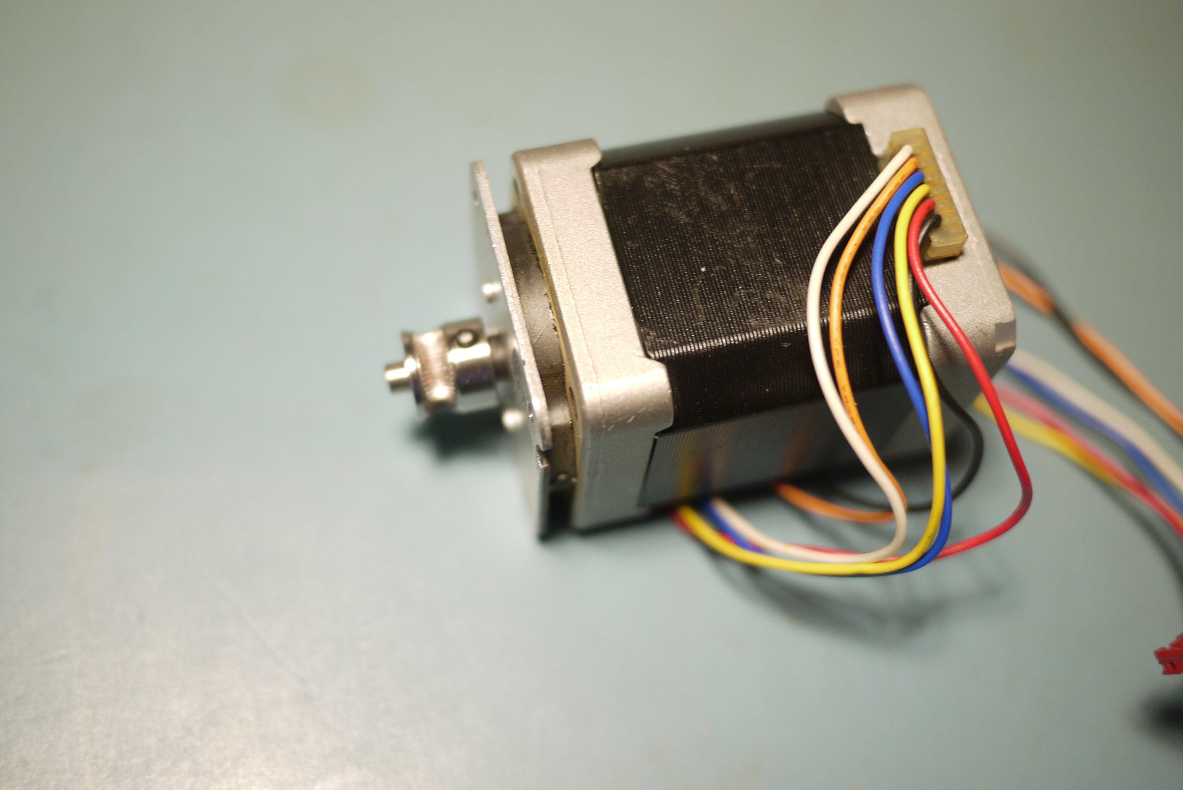
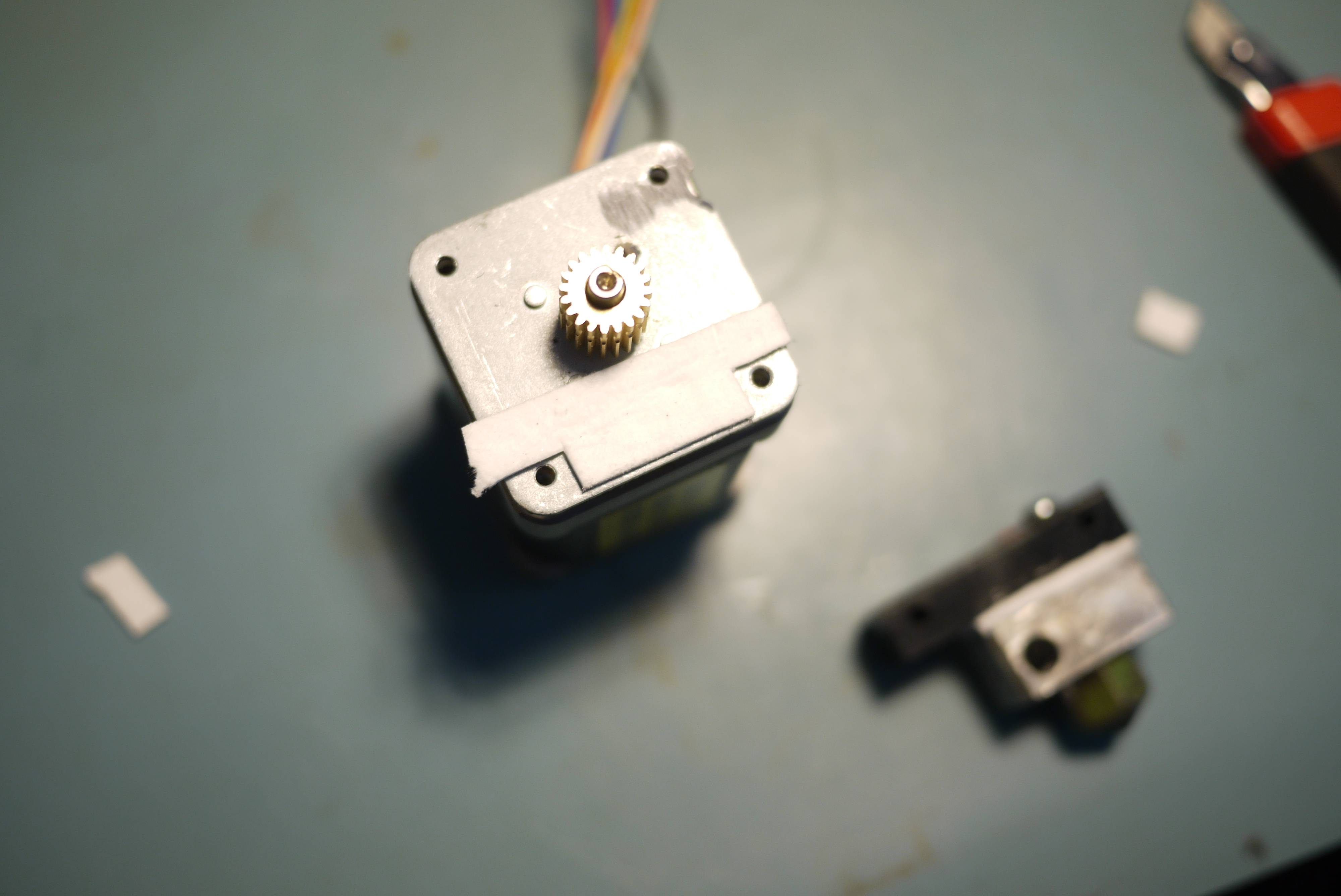
| Building
a 3mm QU-BD extruder To step-extrude 3mm plastic, you need to start off with a big stepper. Seriously, check this example from the days of MK5 extruders. The stepper model I found was crafted from Miters, and had absolutely stellar dimensions. It fit the MK5 extruder gear very well and had a mounting bracket that matched the spacing on a standard nema17 stepper. Note, at this time QU-BD did not actually sell 3mm extruders. This is a 1.75mm extruder modified for this application. |
 |
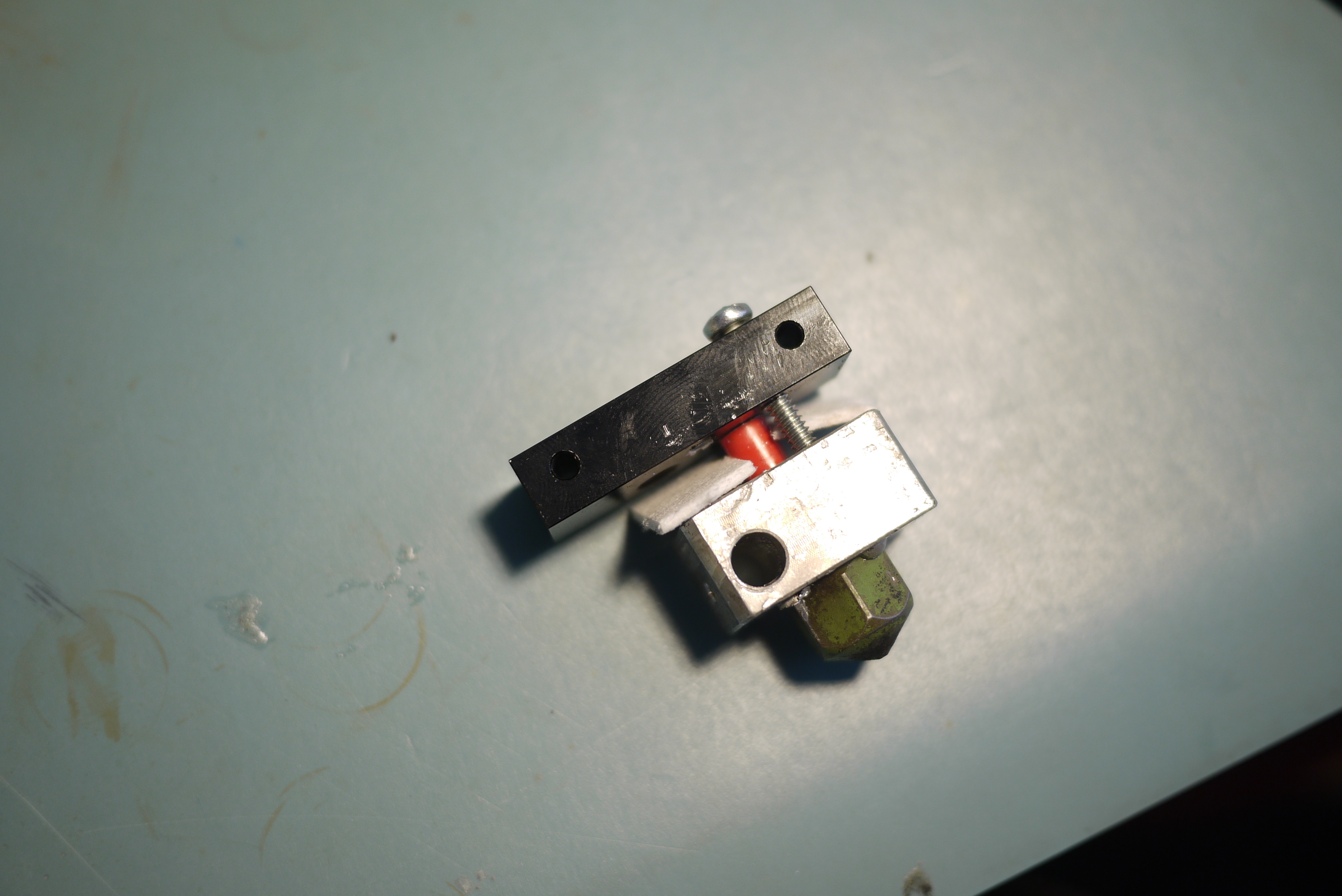 |
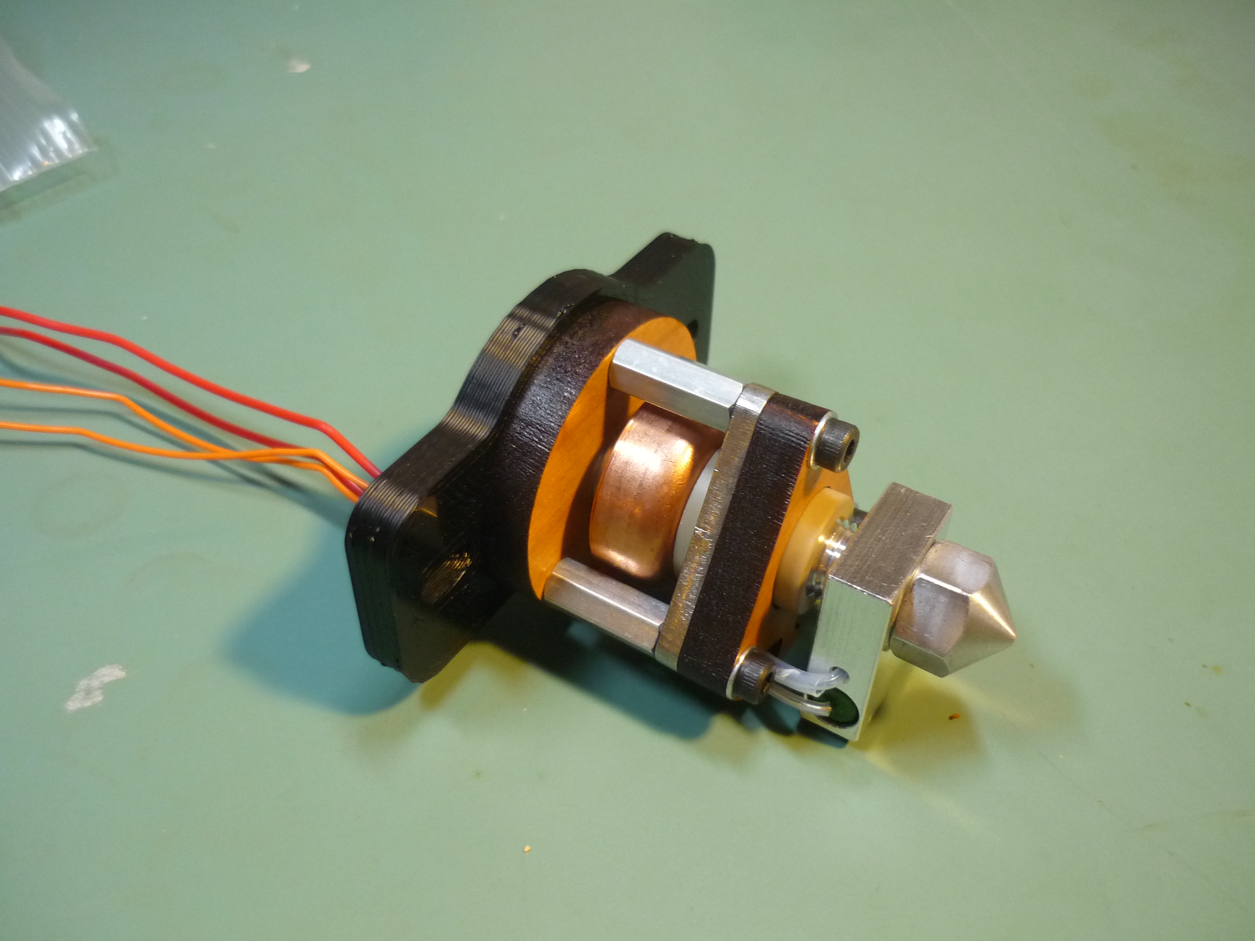
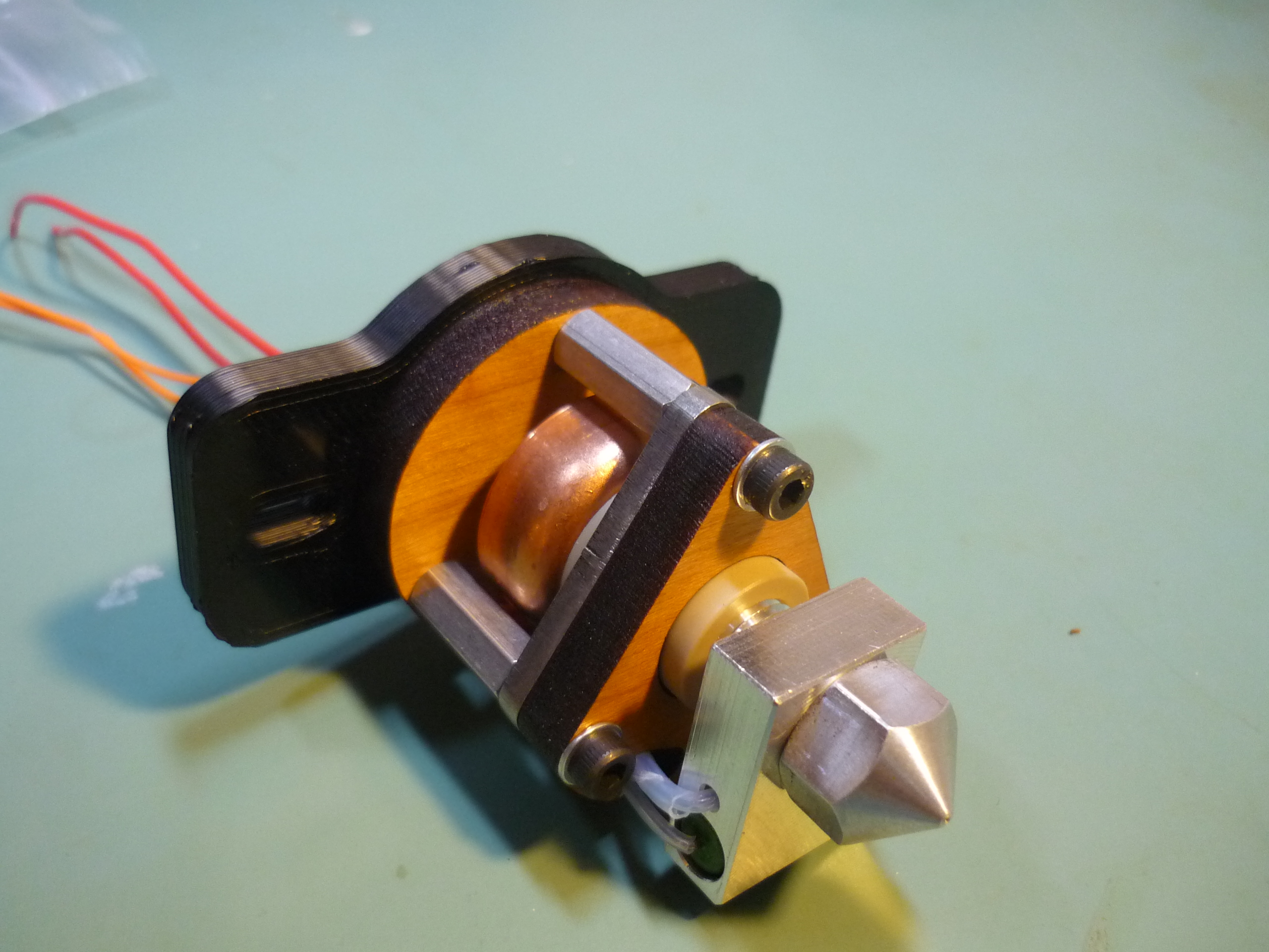
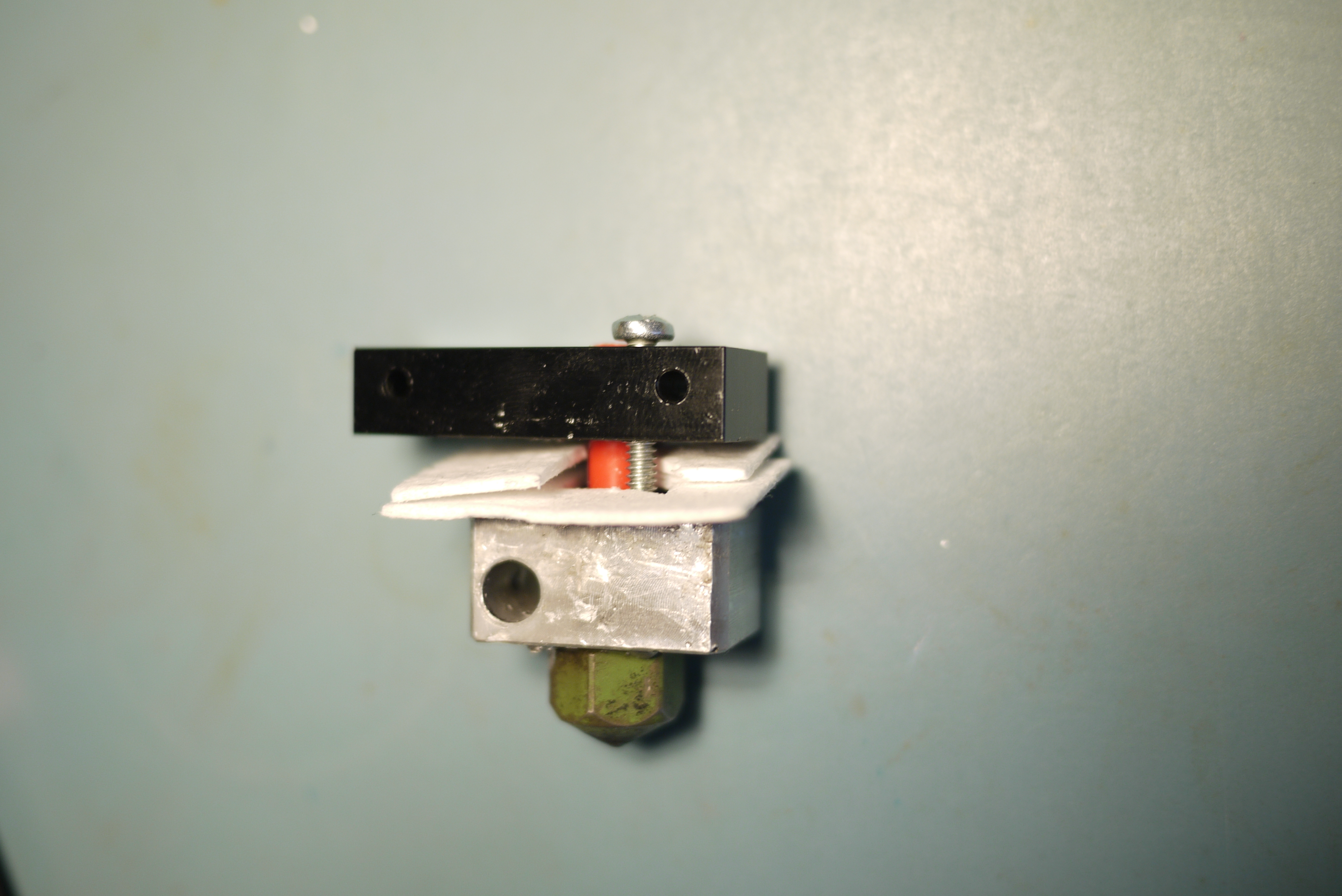
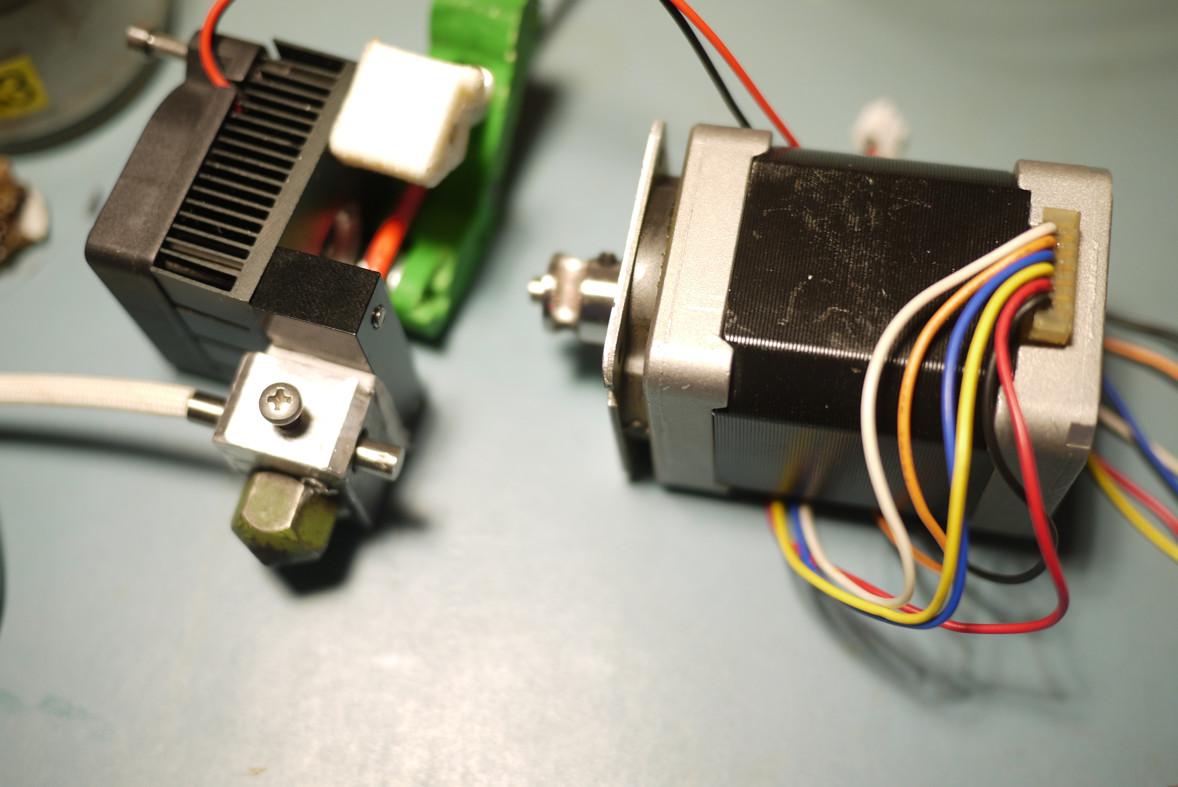
| 3mm
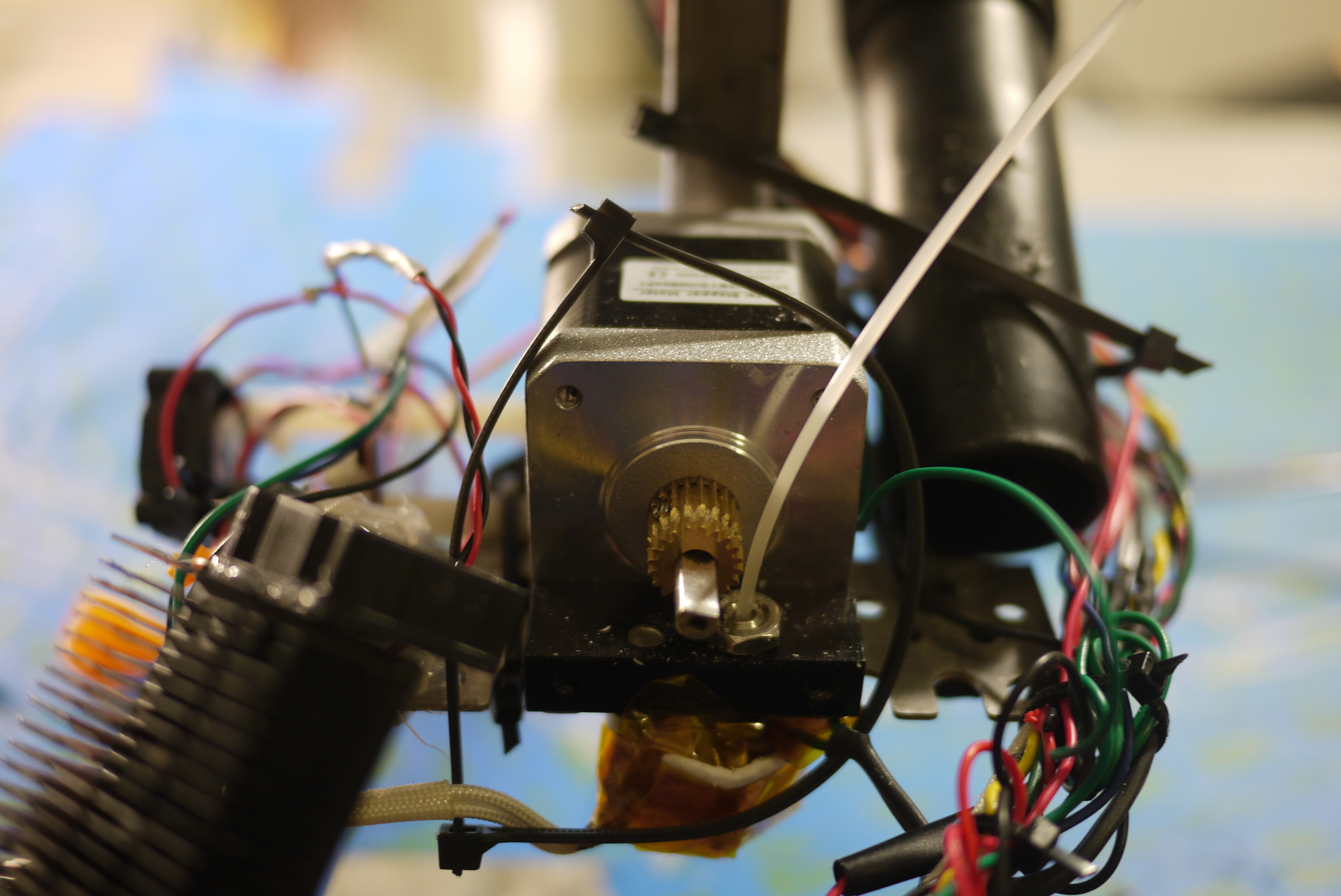
QU-BD extruder build continued To convert the standard qu-bd extrusion head to 3mm, I used some parts from the now-retired MK5 head assembly and parts from the QU-BD kit. Note the qu-bd heater block, and MK5 nozzle, held together by a single screw. The plastic is guided in by a PET 3mm ID tube. To prevent huge thermals from warming up the stepper, insulation tape is used to isolate the heater block from the motor and mounting assembly. |
 |
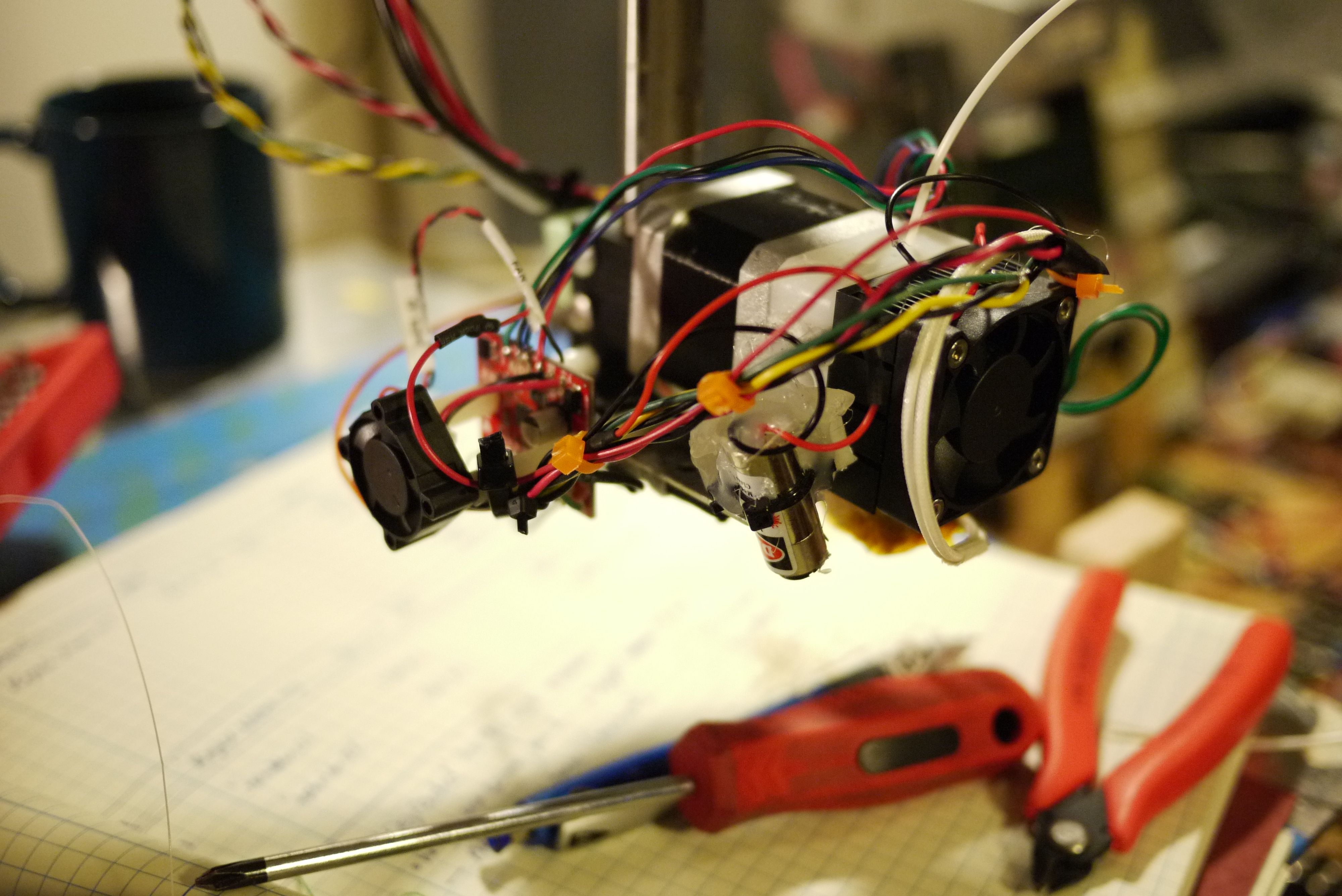
 |
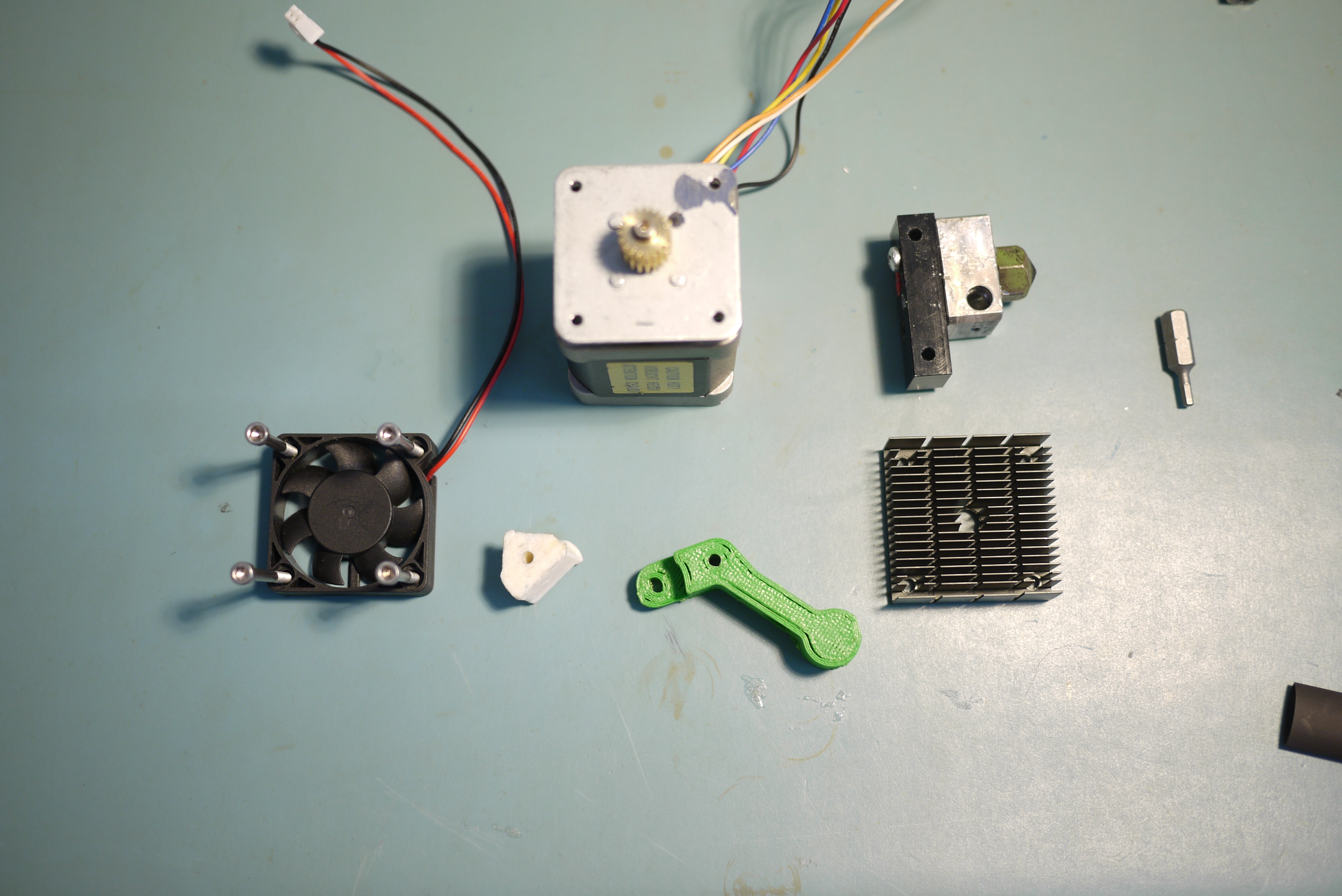
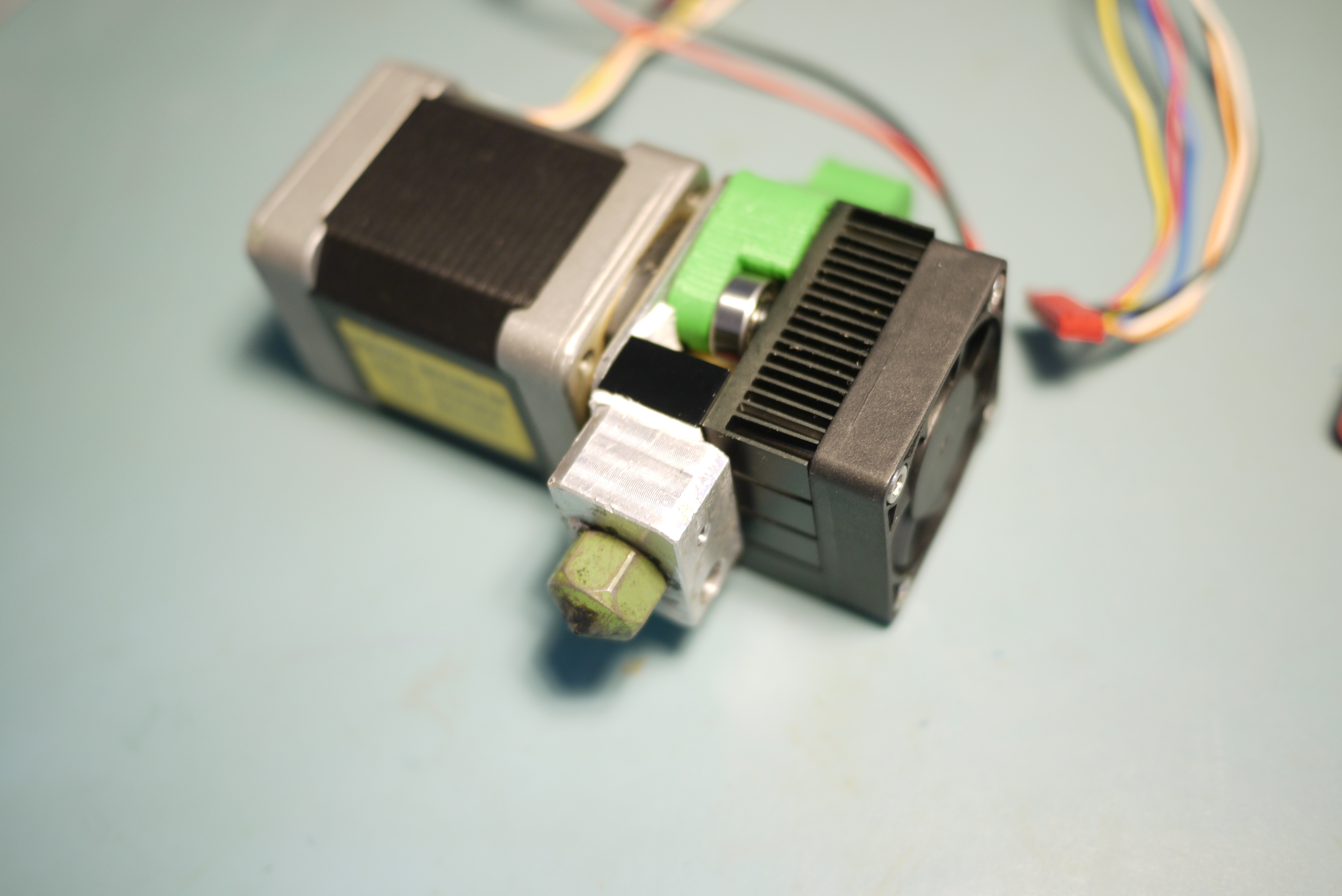
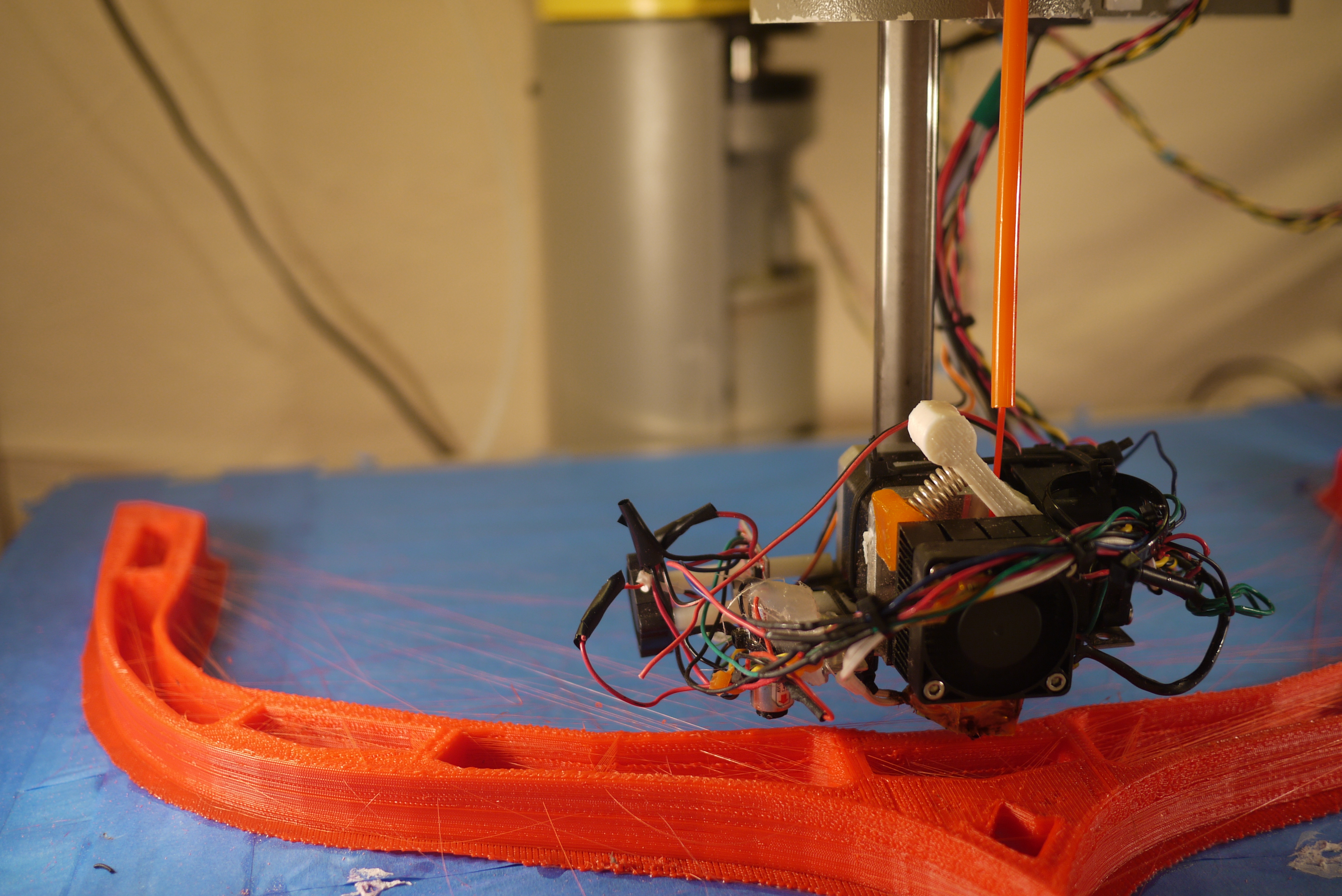
| 3mm QU-BD extruder build continued Shown at the right is the sum of the parts: the spring-loaded lever arm, heat sink, fan, mondo-stepper and MK5 gearhead. Note, I switched over to Green ABS plastic for the lever arm, as it was slightly less flexible. |
 |
 |
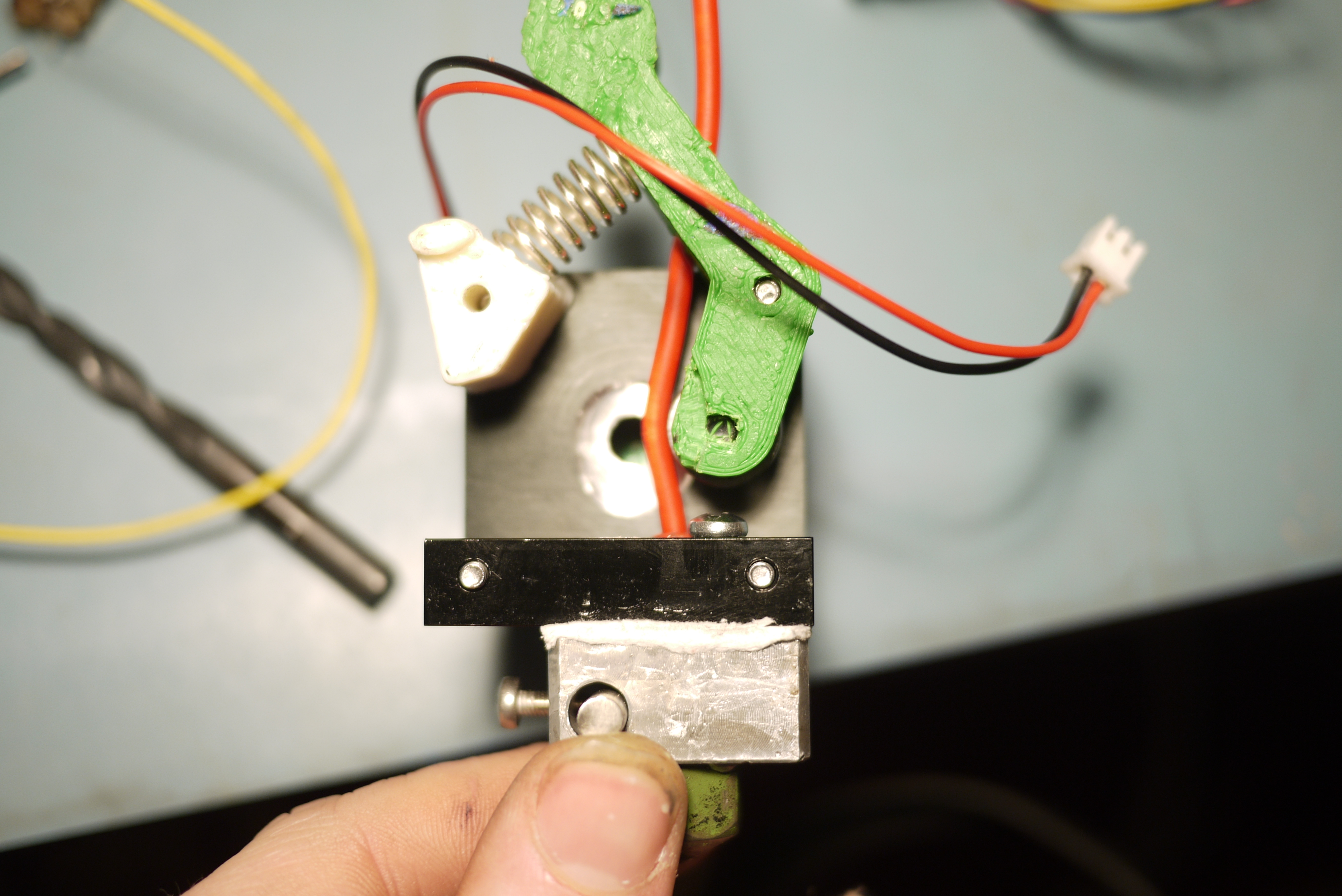
| Insides
of a 3mm Converted QU-BD extruder To allow for clearance on the fan-assembly, the pass-through hole was drilled out because the mondo-stepper needed increased spacing. The spring-loaded assembly shows the force applied to the inbound filament, pressing it against the extrusion gear. |
 |
 |
| One Loooong Extruder coming right
up. The finished MK1 assembly tied up, and bolted together. Note that there is little heatsinking or cooling on the MK1 layout, something that may be added to keep the stepper cool during long prints at a later date. |
 |
 |
Filament Feed
| MK1 to MK4 filament feeds; a bit of trial and optimization | ||
| At
first, the printer ran with a 3mm ABS extrusion head, and a high-torque
dc-gearmotor. I added a spool holder hoisted above the theta2 joint,
using basic aluminum extrusions and mounting hardware. While this
worked fairly well and generally didn't have any issues, it did add
quite a bit of 'sprung' mass to the arm assembly. As any movement required the move of the robot, extrusion head and mass hoisted well above the machine. Relocating the mass off the machine would reduce some offset mass induced springy-ness, which should be reflected in the 3d printed model accuracy. |
 |
 |
| After
the upgrade to the stepper-extruder, with the goal of switching to dual
extrusion (1.75mm and 3mm) I started working on an external plastic
filament feed. To do so, I started with some 9mm nylon tubing and designed a printed head that the tubing fit into. This would allow for the external spools to be routed overhead to the top of the SCARA arm. Note the part was printed using 1.75mm natural PLA using the qu-bd stepper driven extrusion head. |
 |
 |
| Nylon
tubing holder v2 The initial tubing holder was a bit too tiny and flexed menacingly, so I quickly designed an upgraded, reinforced mount. Note the mount is printed with 1.75mm natural PLA, on a heated 'painters-tape' covered platform. |
 |
 |
| Overhead
plastic part 1 The first plan was to route two large 3/4" thick tubes from the right side of the robot over to the top of the theta 2 axis. This should provide a simple guided path for either 1.75 or 3mm plastics. I allowed for a large amount of extra tubing as any complex maneuver resulted in the tubing twisting. |
 |
 |
| Initial
issues with spindle location One of the first issues with this approach was the location of the spools, while not noticeable on small prints, the first theta axis actually bumps into that space fairly often with larger sized printouts (shown in the far-right image). It needed to either re-locate or I would need to shrink the build platform. Move it shall! |
 |
 |
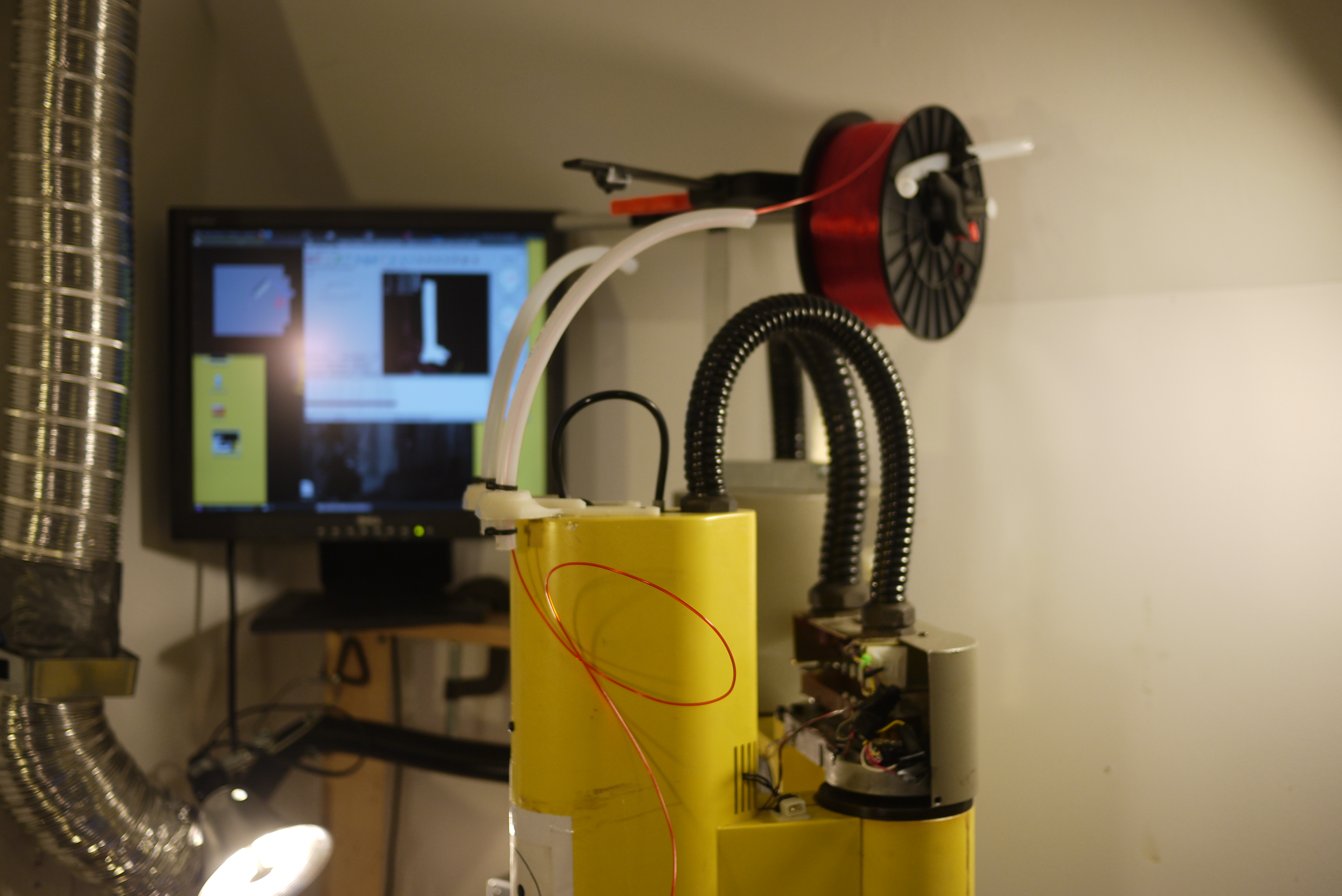
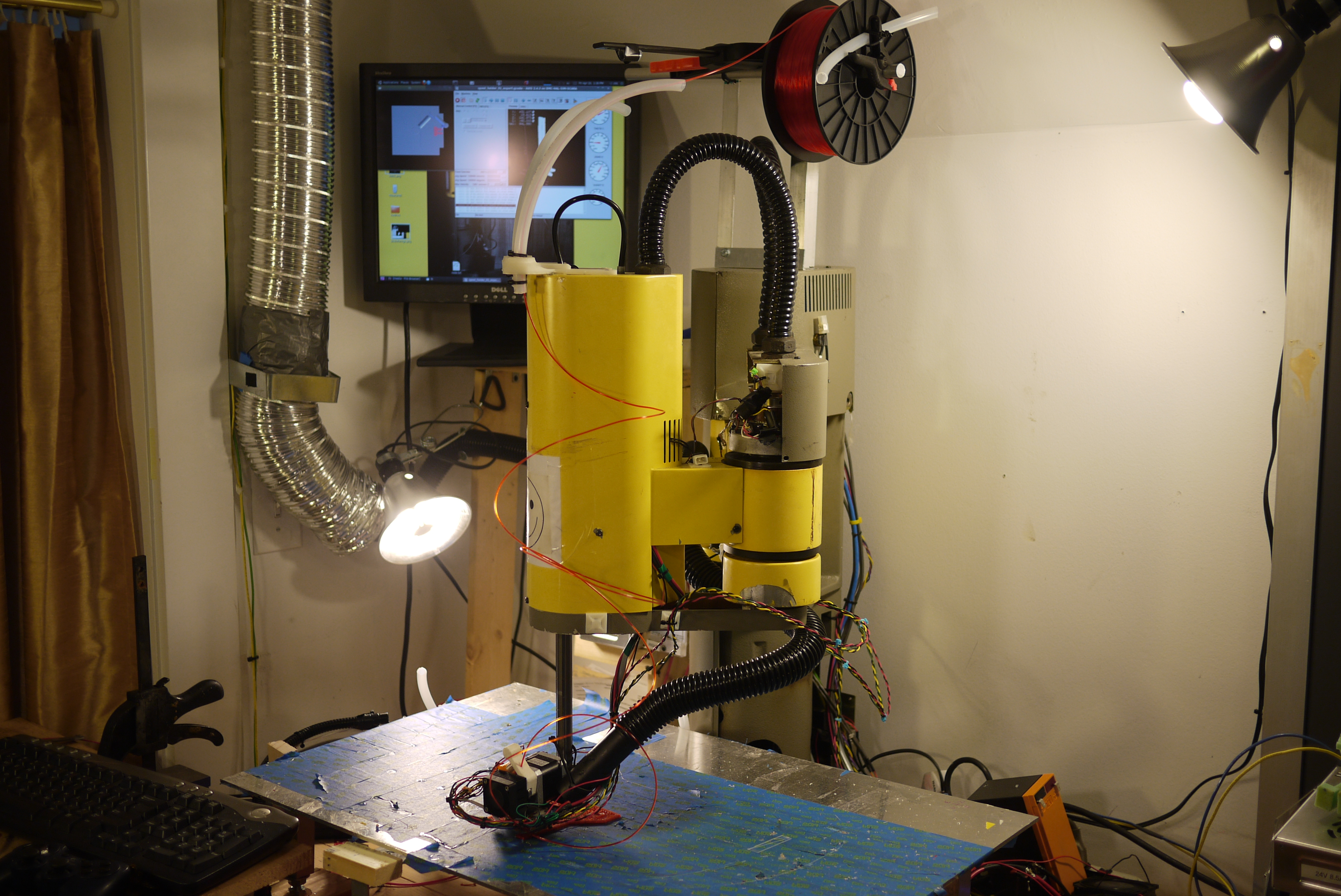
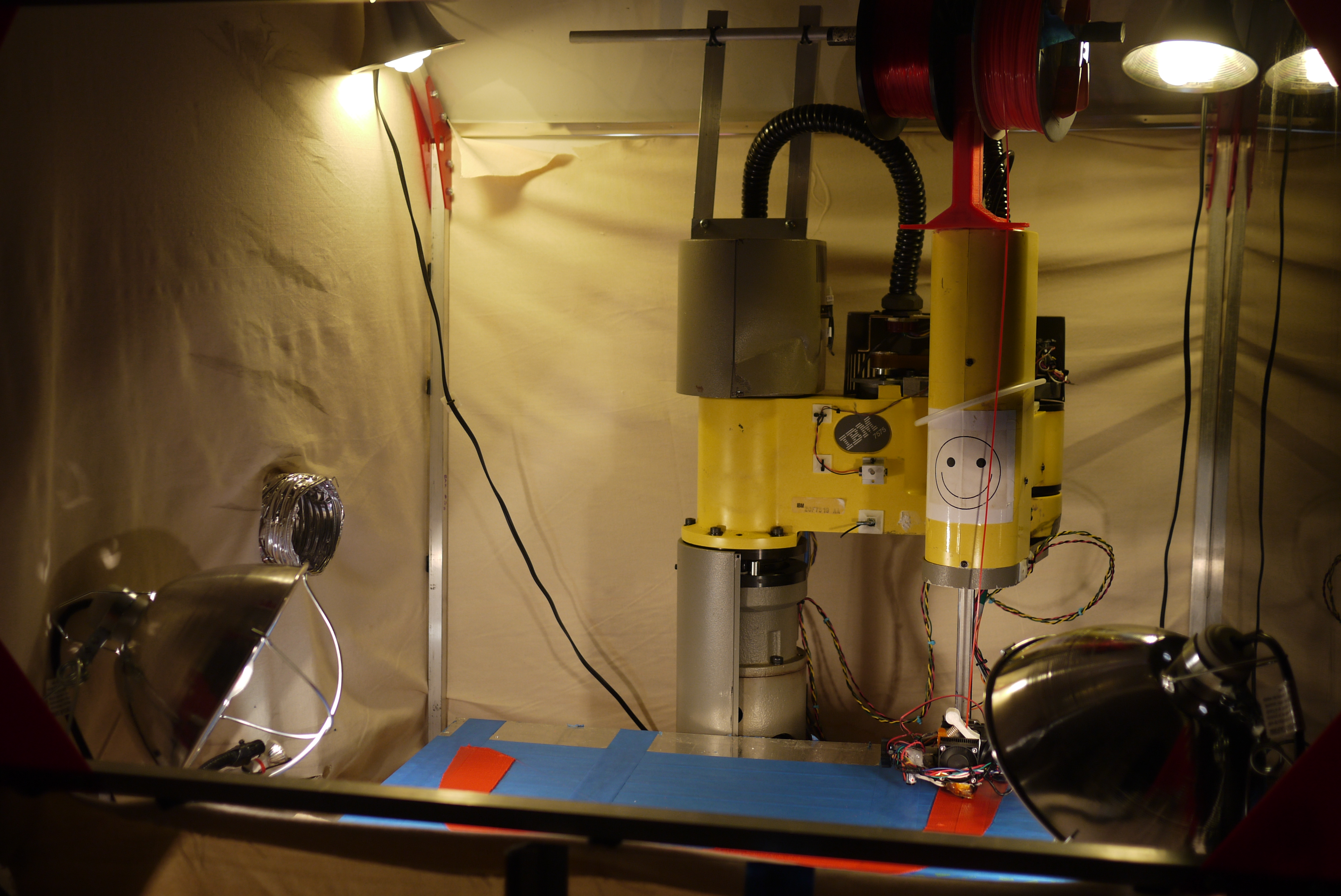
| Overhead
spools and shortened feeds I relocated the spools above the machine with a similar tube for guiding the plastic to the print head. I ran into trouble, to much friction! It turned out that as the machine twisted about the plastic tubing would turn and the contact area resulted in twists in the filament feed, resulting in sporadic jamming roughly every hour. Shortening the filament routes helped a bit, but looked silly and still had sporadic jams. |
 |
 |
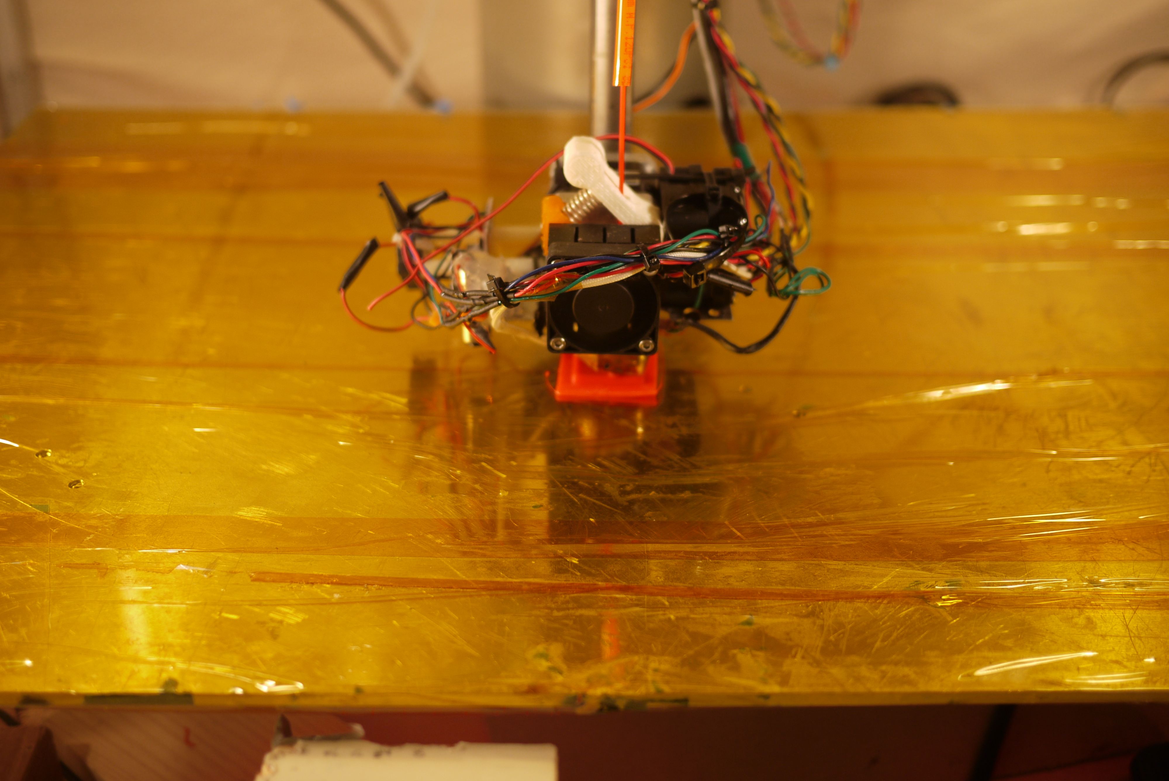
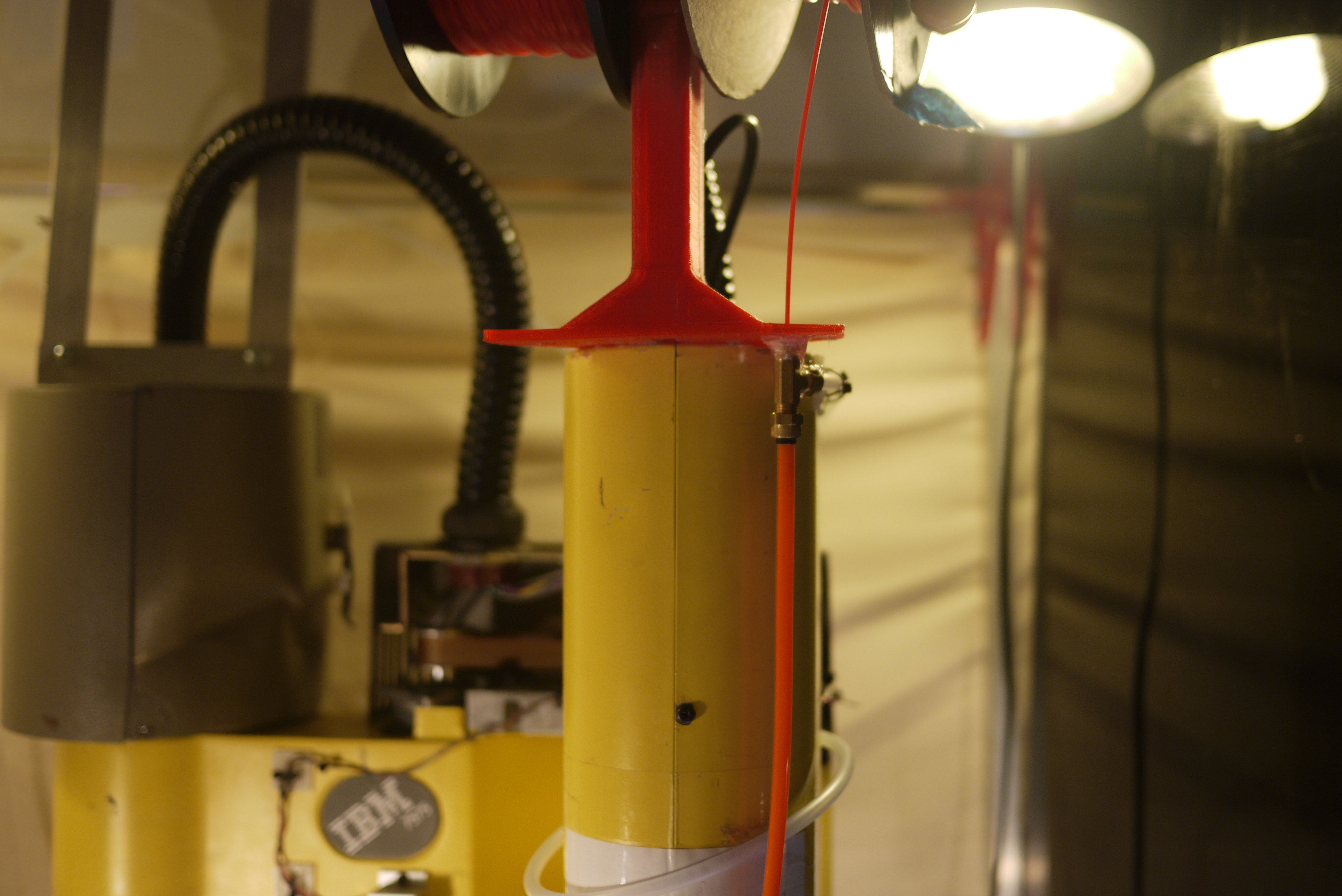
| Spool holder adapter For the V4 spool holder, I came full circle and finally decided to move the spools back onto the robot. After attempting everything aside from assisting the plastic feed through the piping with a secondary motor, I came to the conclusion that a properly designed, holder shouldnt effect print quality that much. So begins the 'spool-holder mk4' printed with shiny-red 1.75mm PLA. Note this was printed with the existing overhead tube-based plastic feed, so, there was a constant need to 'relieve' any stress on the extrusion drive by pulling ~3-5 ft of plastic ahead of the extruder. As was the issue with the previous tube-feed design, it was easy to get snagged and stop extruding. |
 |
 |
| Snagged?
build an extension bar During the fairly long print, for the new dual-spool holder, the feed got snagged while i took a nap. Instead of re-printing for the extra 3 inches, i chose to quickly CAD an extension, generate an STL and print. |
 |
 |
| YOWZA The new spool holder worked really well. As shown in the CAD [solidworks] [stl] [jpg], a steel bar fits across the top-section and locks in place with four zip-ties. I added in some epoxy to prevent the unlikely case of it slowly escaping. Shown right are some canoe-test-parts being printed from leftover red PLA. That part is roughly 30 inches across. Due to the low coeficent of thermal expansion of PLA, this part has very little warp. |
 |
 |
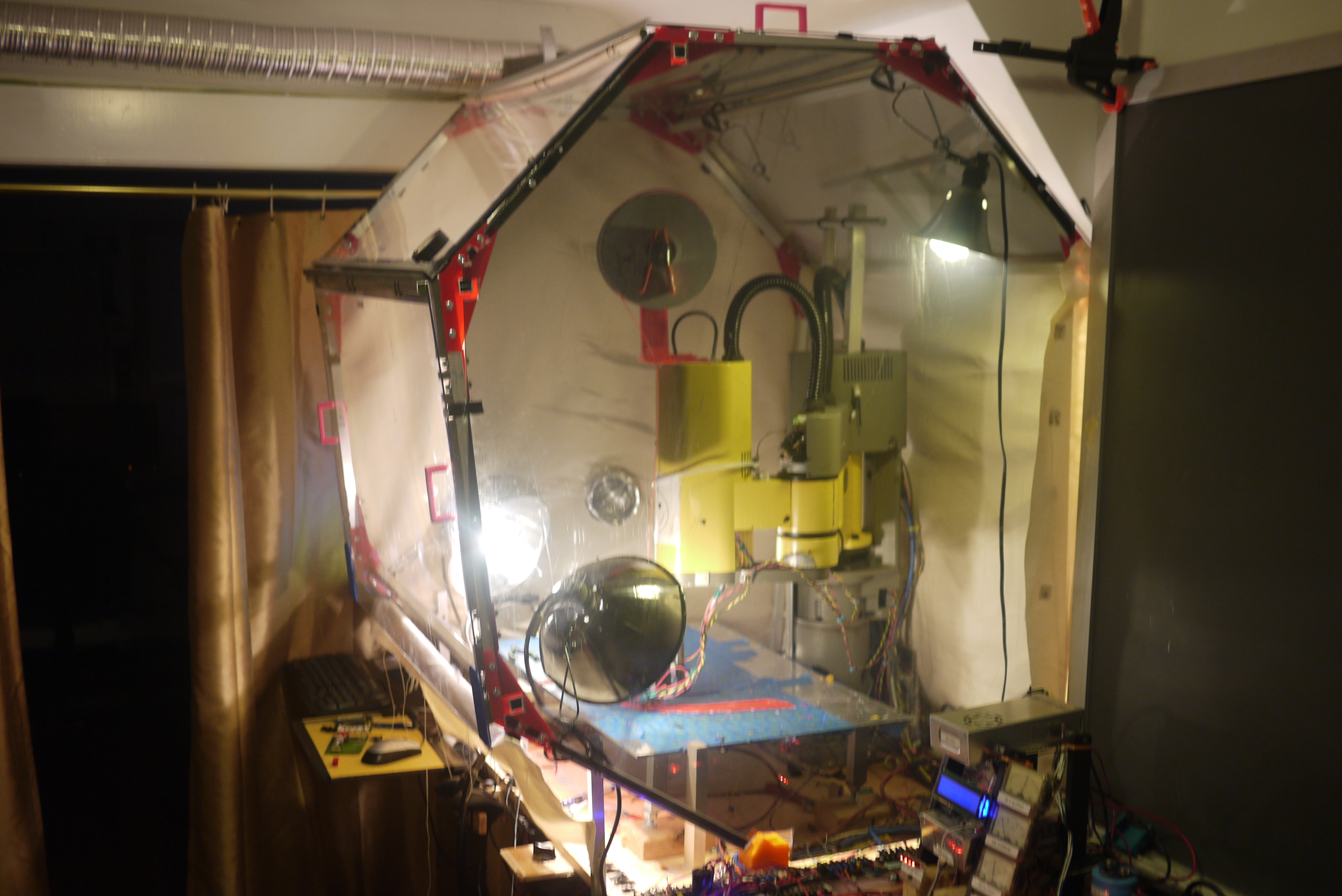
Thermal Chamber
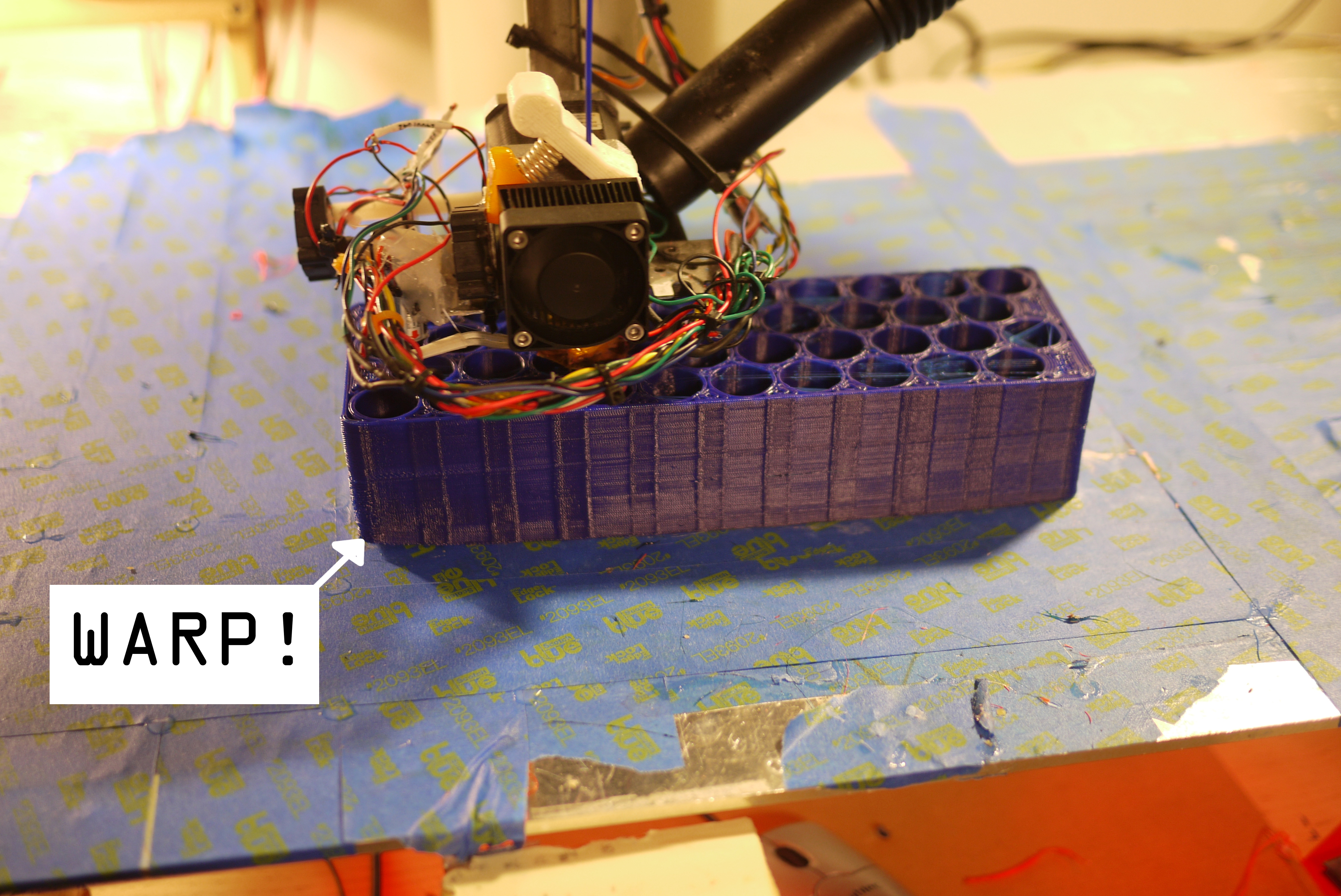
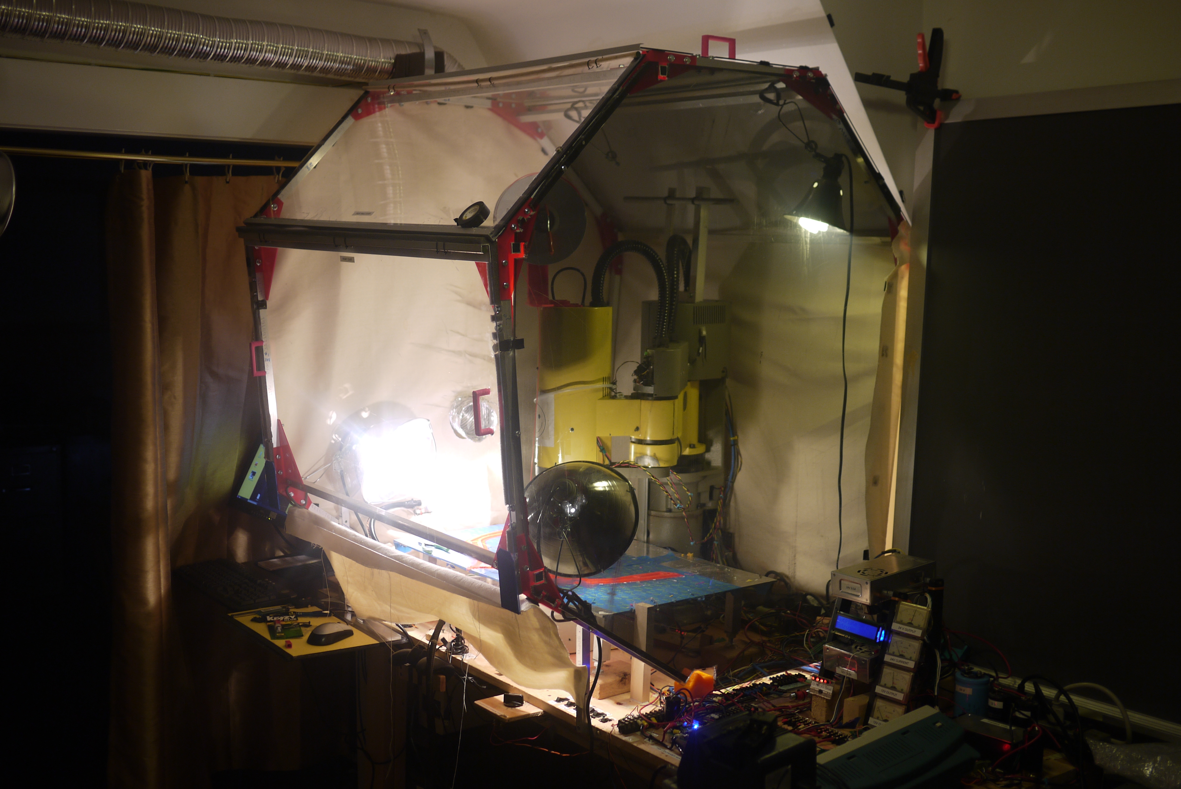
| Giant Semi-Hexagonal box of warm | ||
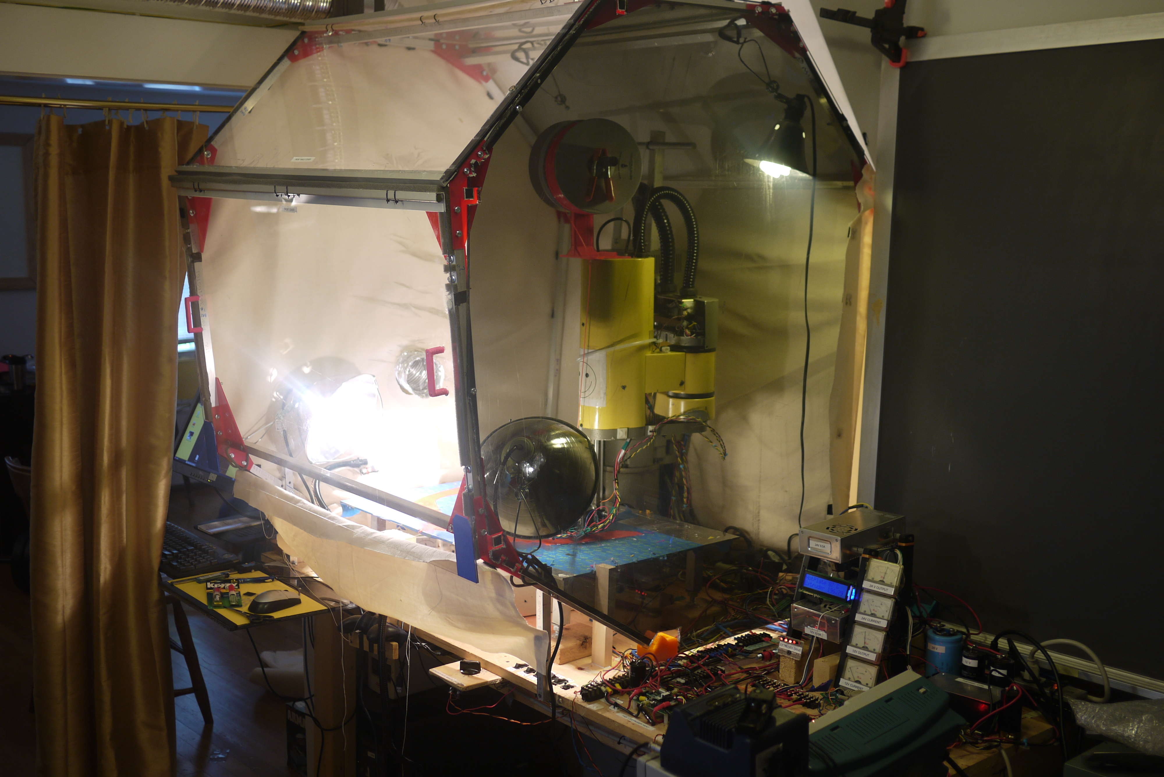
| To
print very large
parts out of ABS, a heated build platform is one of the only ways
around 'the warp'. For short parts, a heated build platform alone can
permit non-warpy parts, however as the part skirts off a few inches
above the platform, its no longer bathed in the warm rising air, and
begins to contract. For large, tall parts the only workaround is to
prevent the ABS from ever getting to the point where it starts to warp.
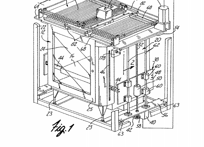
This requires a chamber full of air, warmed to ~65-75C. Industrial
machines, (stratasys) use heated chambers, and have patents preventing
others from duplicating the aforesaid box of heat. [patent link] |
 |
 |
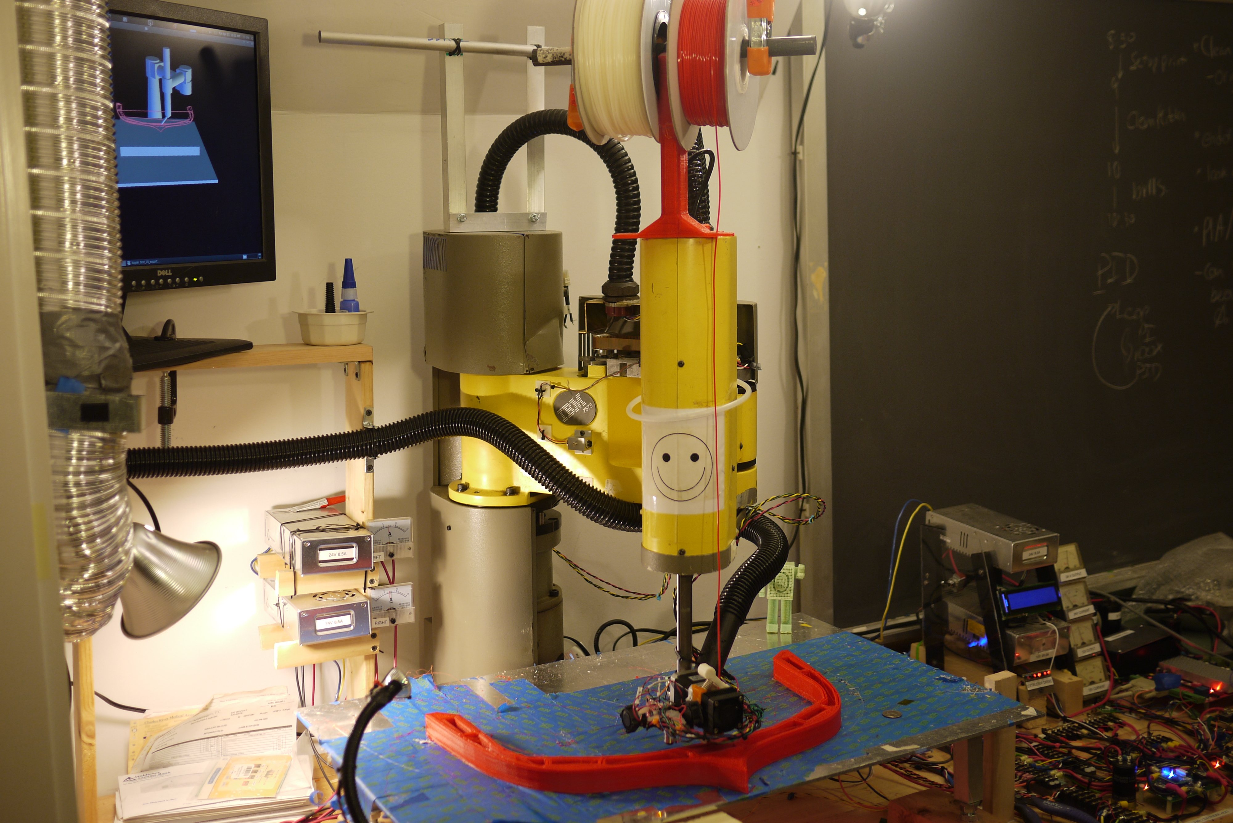
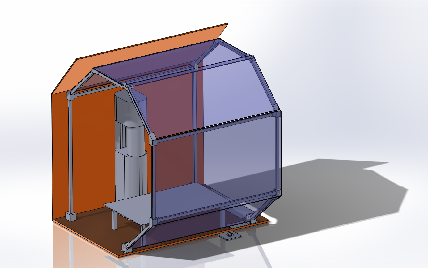
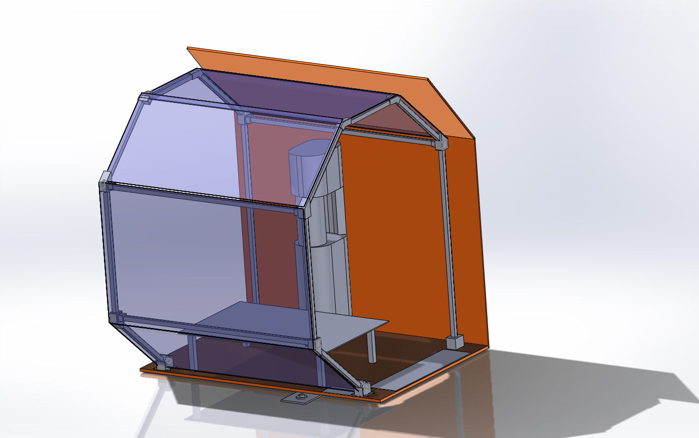
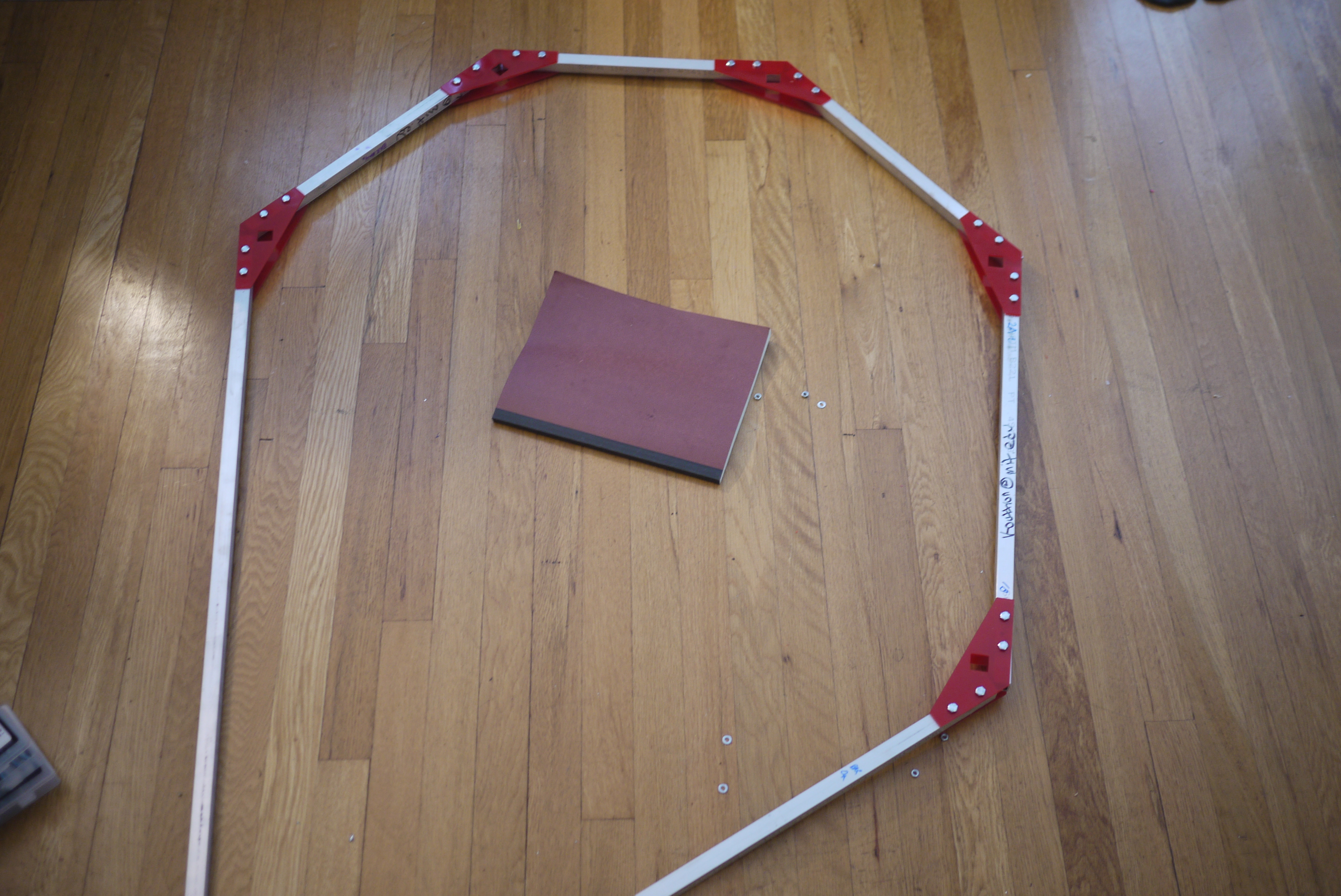
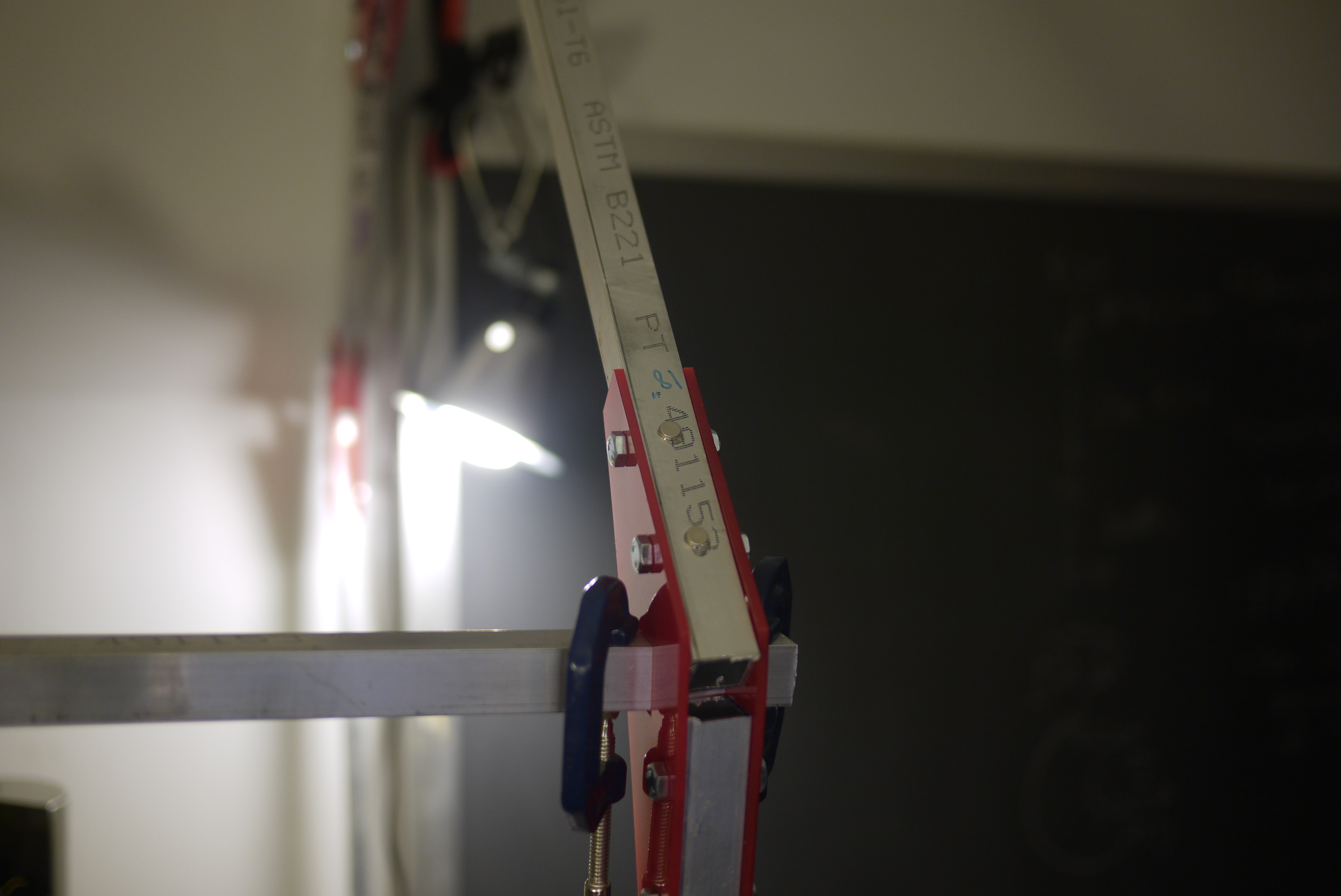
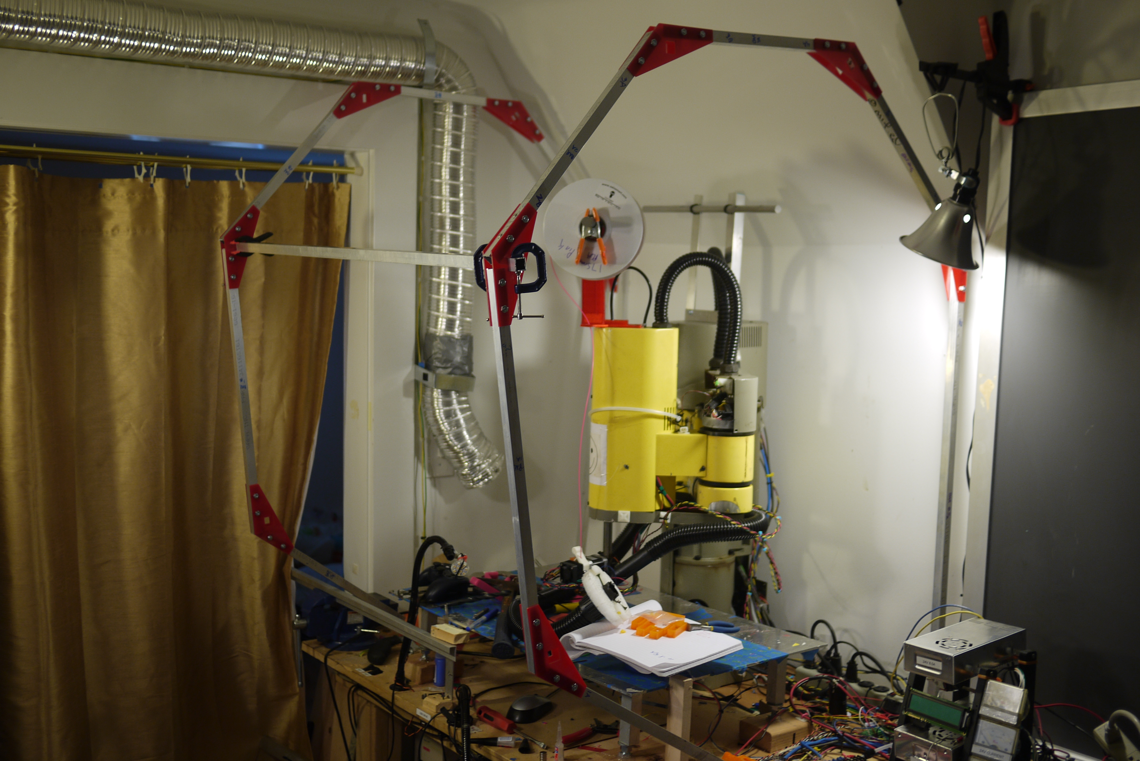
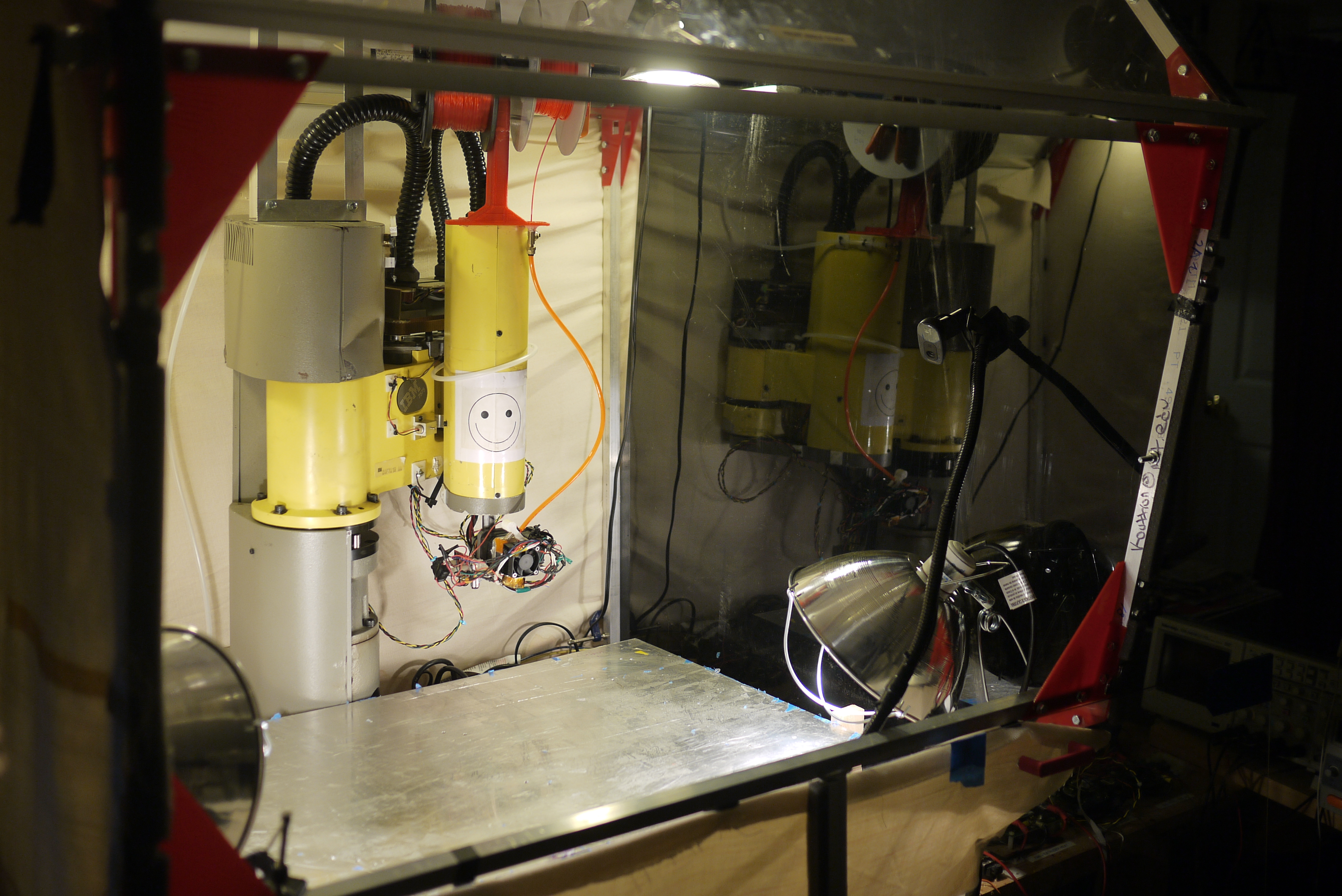
| Designing
an easily disassembable frame I was lucky enough to come across some 0.8 OD" square aluminum extrusion, which was excellent for designing / building a 'cage' around the printer. I opted for the 'strange jungle-gym-apparatus' approach, using printed joint mechanisms as the mating mechanism between parts. Note the sides in the first revision are open. I chose to just opt for some heavy cloth, magnet-clamped to the frame, instead of purchasing / cutting enormous sheets of polycarbonate. Model of chamber [solidworks] |
 |
 |
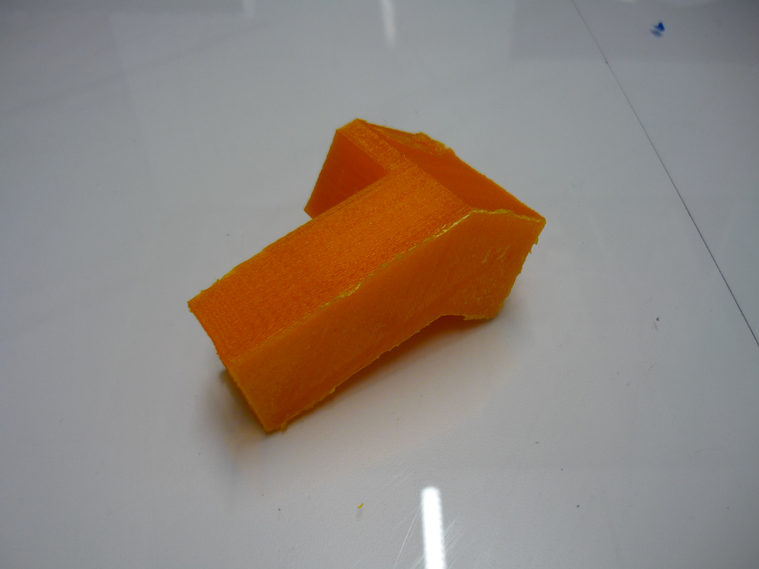
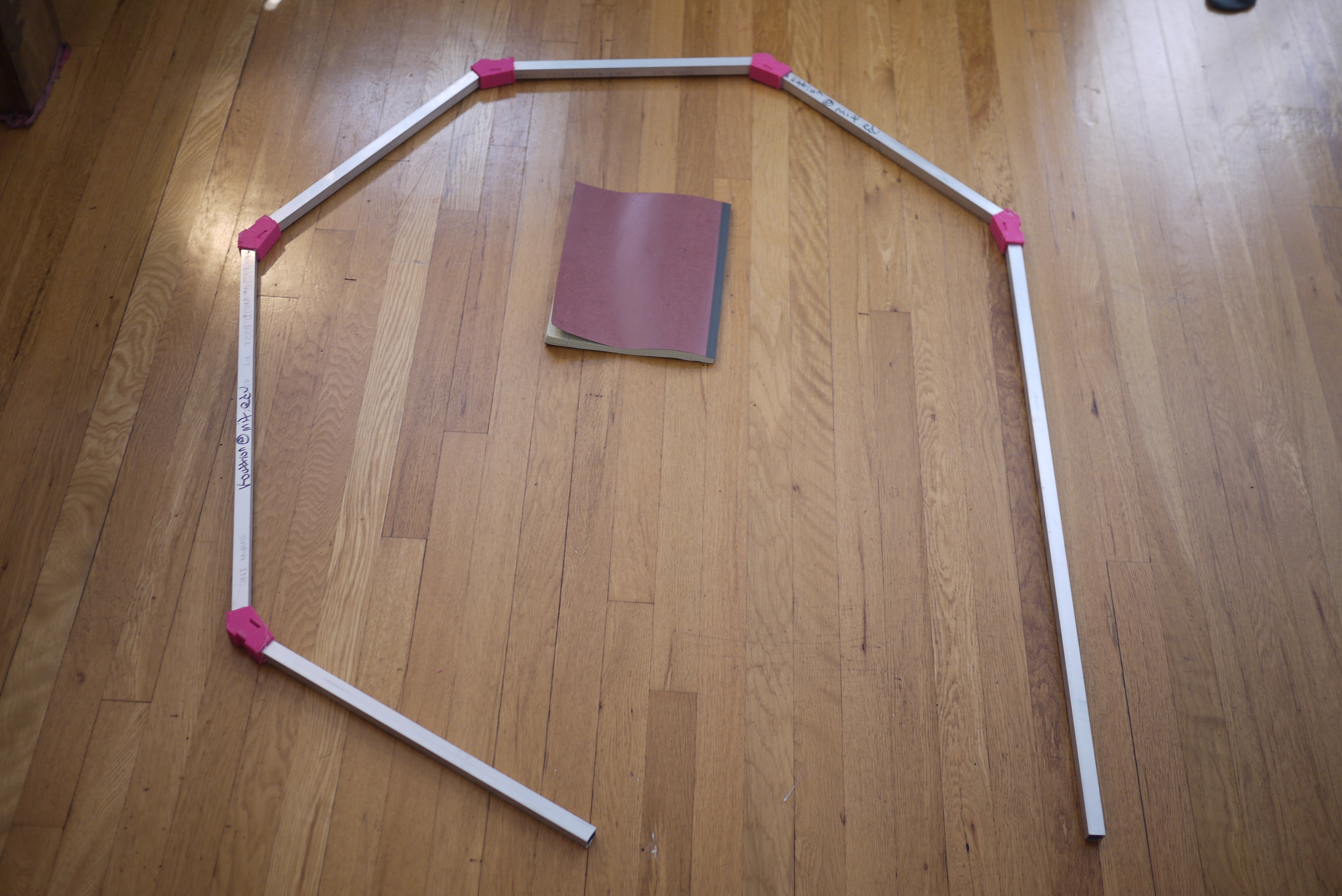
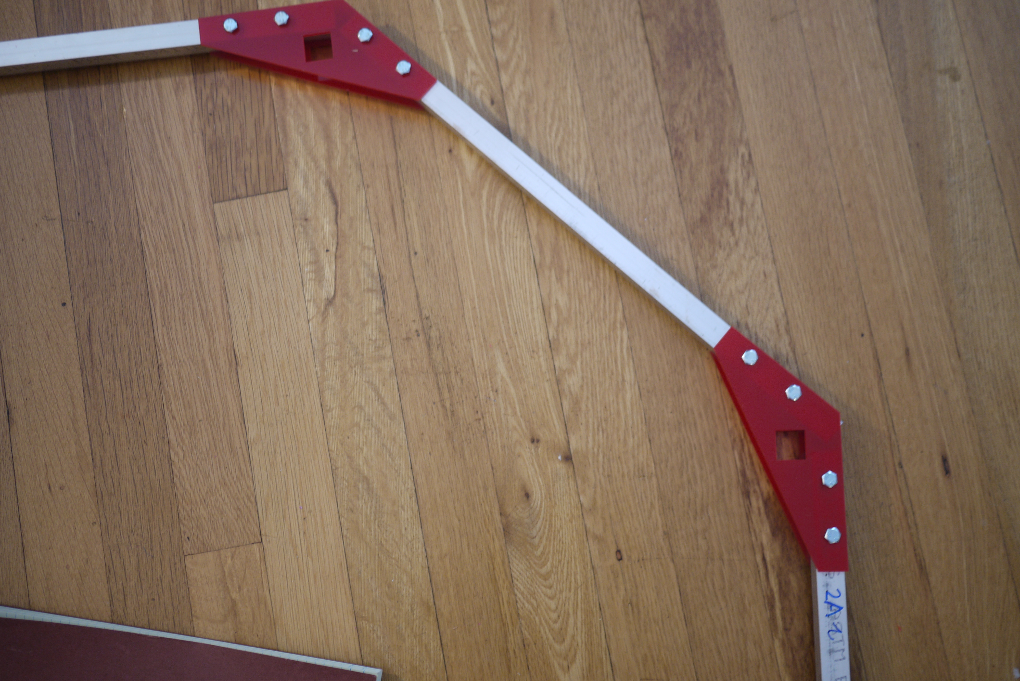
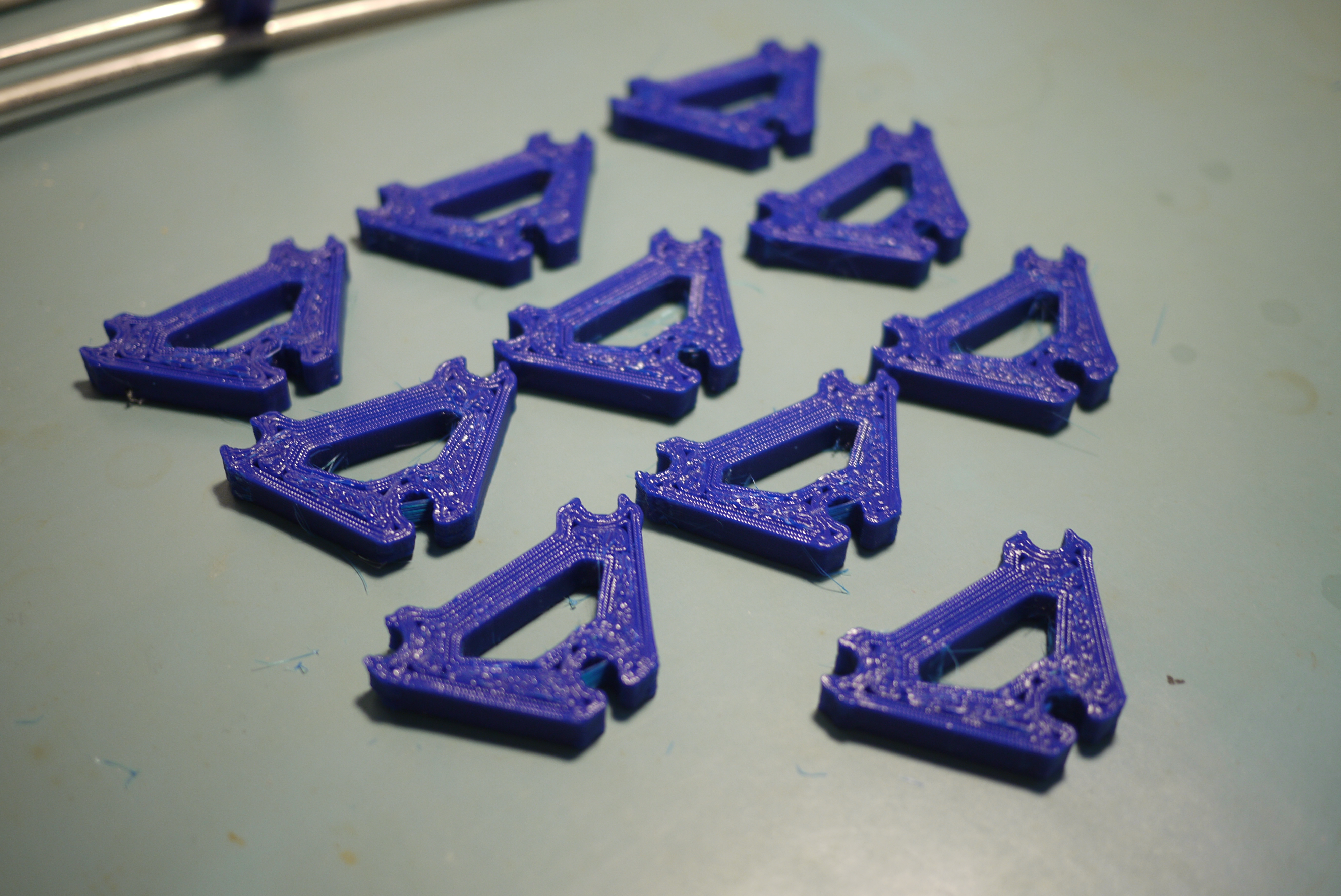
| Extruded
Tubing Braces Initially I attempted using 3d printed ABS parts for the angle-adapters tying together the chamber, but ran into a few issues. Show far right is a completed side of the chamber, with aluminum extrusions inserted into 3d printed angle-holder parts. Unfortunately I underestimated the amount of stress each pink 3d printed angle-bar would be under to hold up such a massive frame. The initial test was underwhelming and a bit too flexible. Instead of just opting for larger printed parts, I moved towards lasercut-acrylic. |
 |
 |
| Acrylic cuts and M6 Bolts To increase the rigidly of the heated build chamber, acrylic parts were cut, from scrap 0.25" acrylic, to mirror the shape from the initial CAD model. Note the acrylic brackets have an internal 0.8" hole for lateral aluminum extrusions. These parts should hold up better in a warmer environment, versus the printed ABS counterparts |
 |
 |
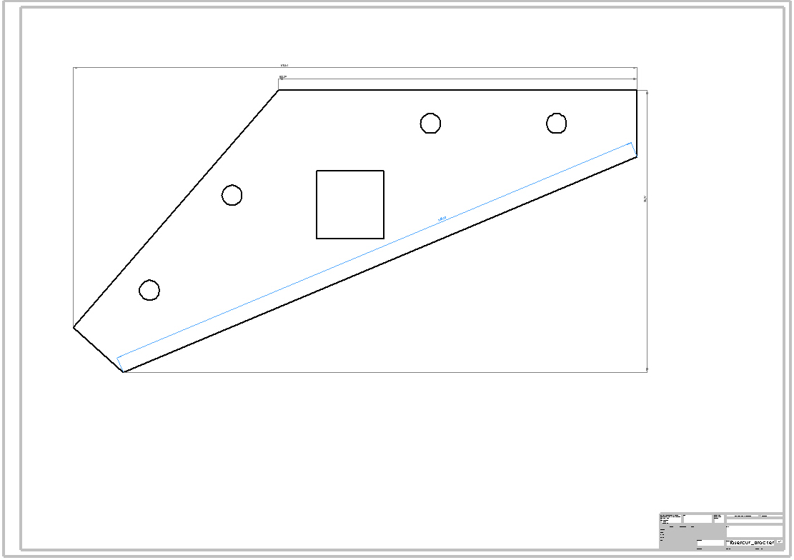
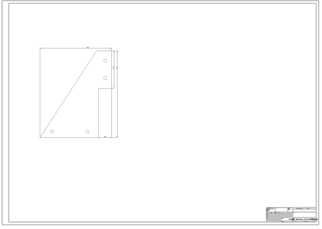
| CAD
for lasercut parts and some quick notes Lasercut parts offer really nice, repeatable shapes, unfortunately super-strong polycarb isnt terribly laser-cutter-able, while acrylic is. For the frame members I opted for using *free 0.20 inch thick translucent acrylic. I generated the spacing and bolt pattern in solidworks and was able to make some quick cuts thanks to Charles guan's fantastic shop of science and scooters. Note the 0.8 inch square tube hole for horizontal mounting, the braces for those mounts are an insert that provides reinforcement for lateral loading. Note M6 bolts and nuts were used [link]. For the lasercut parts here's the angle bracket [solidworks] and cross brace [solidworks]. |
 |
 |
| Initial Frame Assembly Using some tiny clamps and some hacksaw action, the two sides of the build chamber were set up and propped into place. The chamber area is rather HUGE. the side-to-side stability is addressed with another acrylic lasercut bolt-on assembly. |
 |
 |
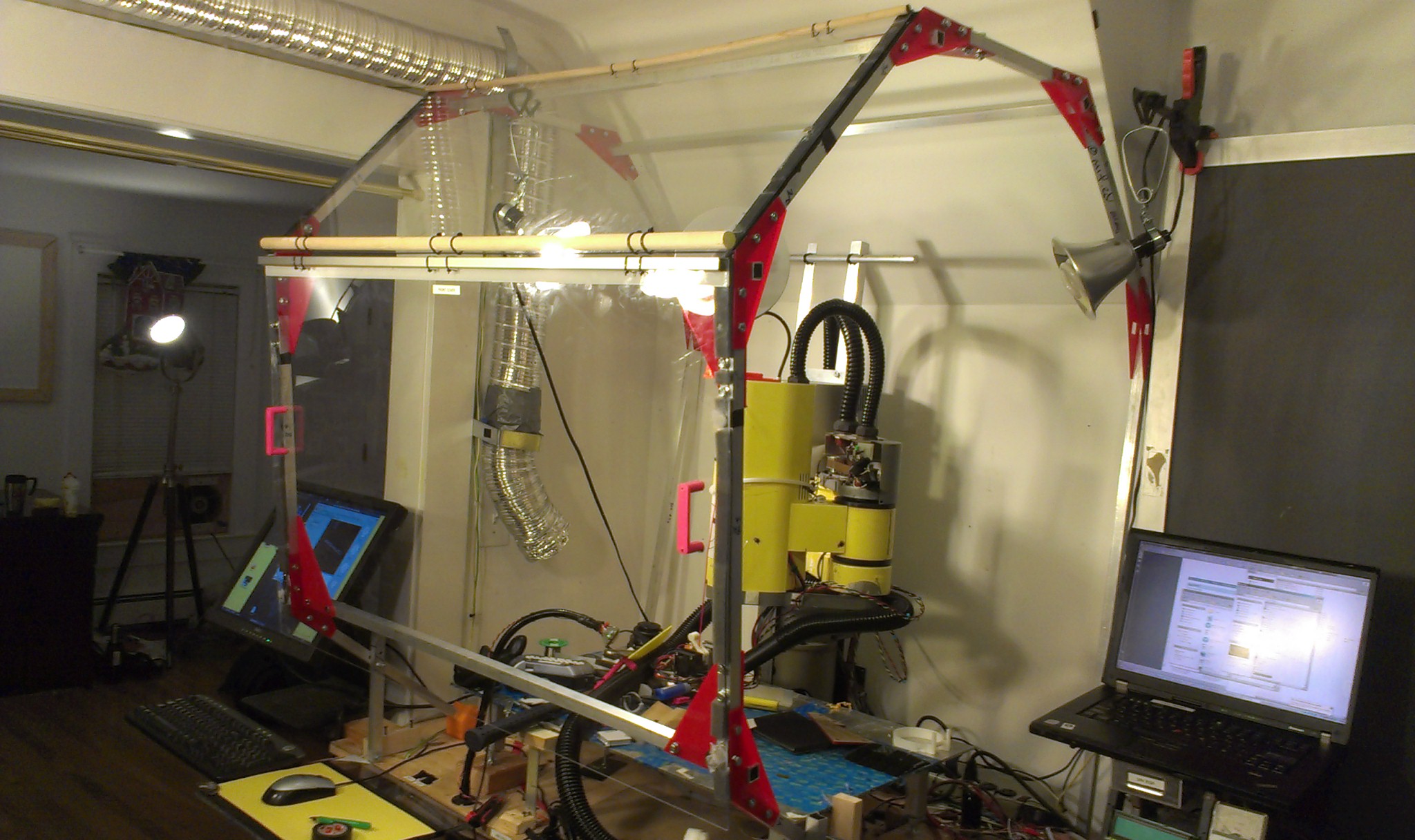
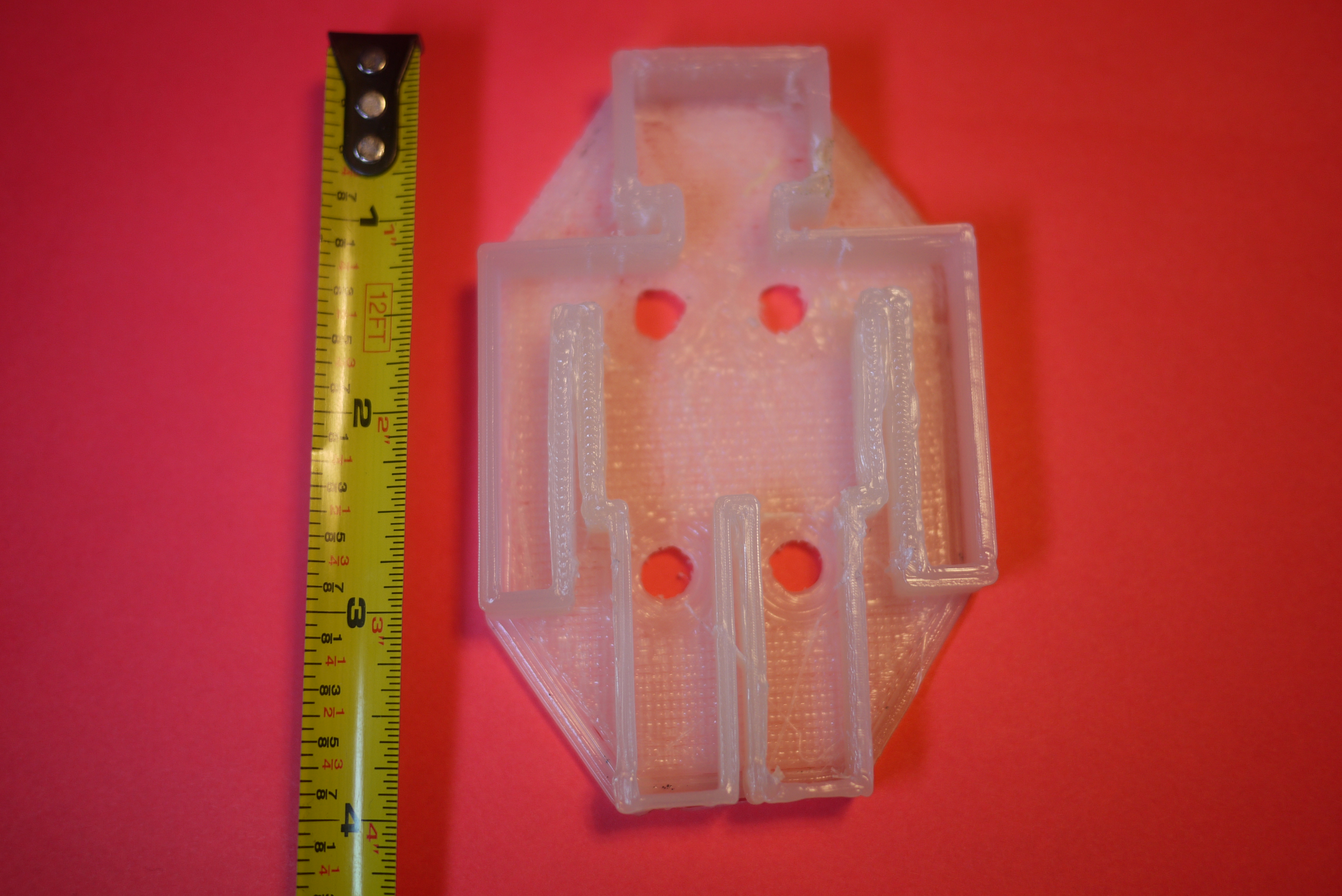
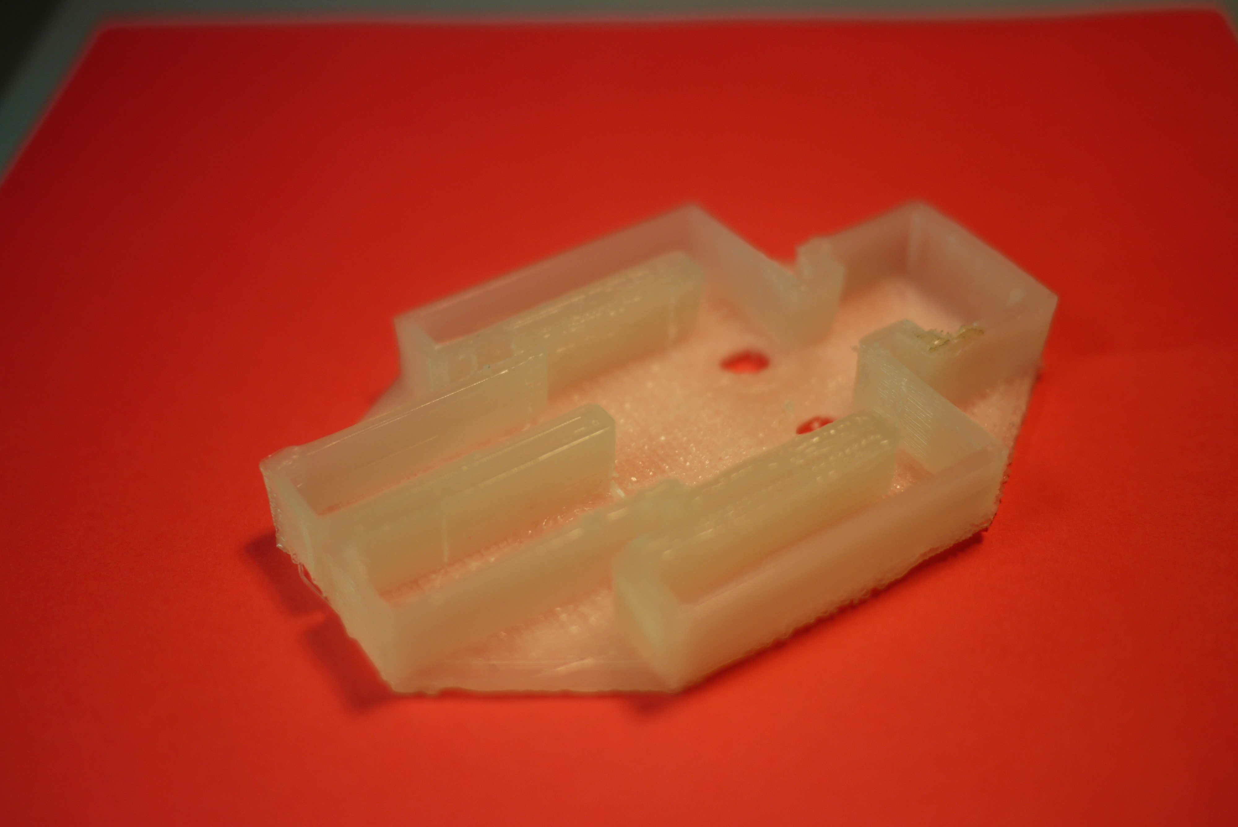
| Polycarbonate & acrylic
inserts, functional handles To fill the large spaces between the aluminum frame, I opted for using clear scrapped polycarbonate / acrylic. I wanted these panels to be removable but also function as a draft blocker / heat retainer. To make it easy-to-remove, but also stiff enough to stay in place, I used a combination of Nd magnets[link], adhesive felt, adhesive Velcro, and 1/2" adhesive weather stripping [link]. Model of handle [stl] [solidworks] |
 |
 |
| More
Polycarb and fitting I purchased some of the 1/8" thick polycarb from altec plastics. I was able to get the first part of my order in the next day, however, the remainder took a while to track down. Note that 1/8" polycarb will droop without horizontal support, something that I initially neglected to take into account. To solve this I found that a combination of aluminum angle rod and RTV epoxy worked wonders. The aluminum added well-needed rigidity while the |
 |
 |
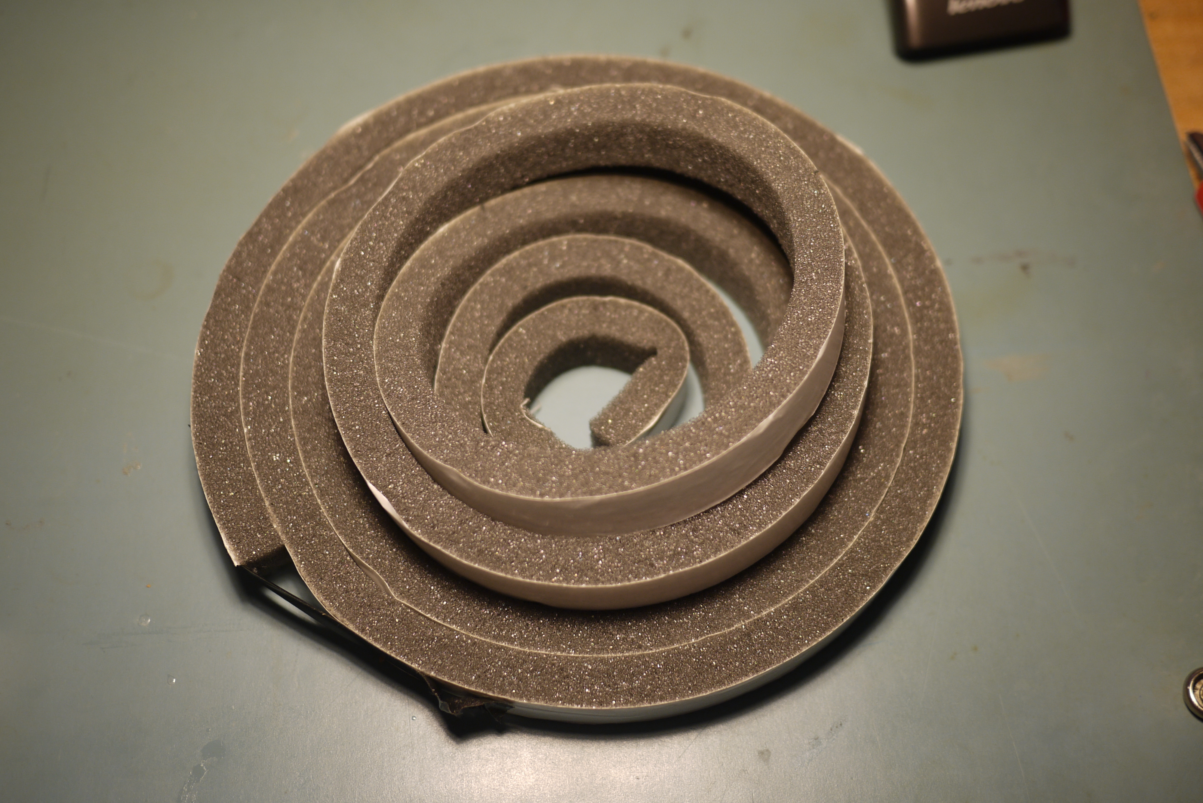
| Velcro,
magnets and foam insulation To fill the gap between any outstanding bolts and the height difference between the acrylic and aluminum extrusion I opted for the fairly cheap, rather excellent, 0.75" thick adhesive foam insulation [link]. The foam created a fairly excellent seal between the gaps. Attachment points for the cloth backing used 1" square Velcro adhesive tabs. With the assistance of loctite CA, they were attached rather firmly, and held together the cloth backing. |
 |
 |
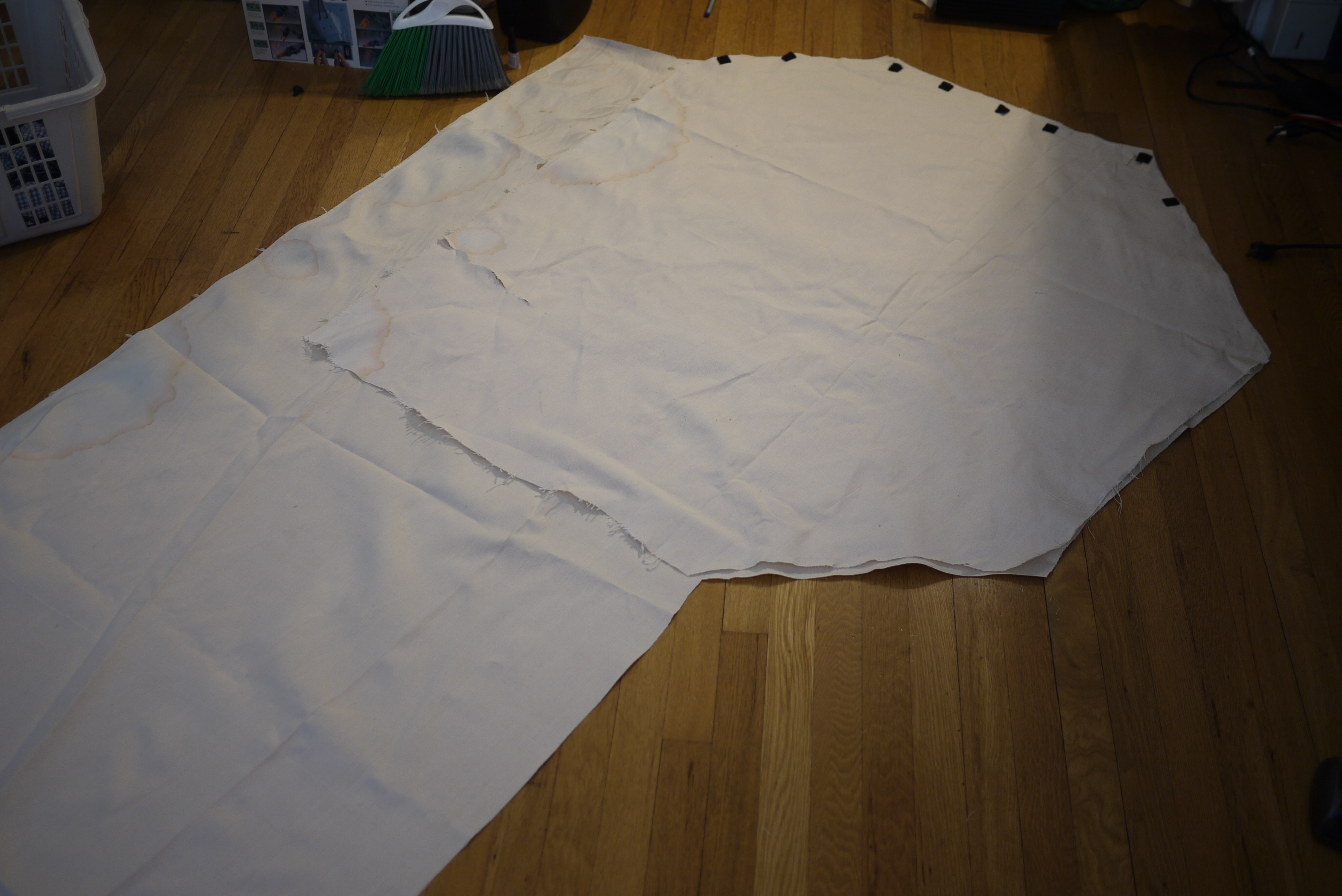
| Blanketing
the side and back Covering the rear and far left side in transparent acrylic would be fairly expensive, and, as that face of the heated build chamber was facing a wall, a transparent siding wasn't really necessary. I instead opted for some heavy cotton cloth, cut to size and velcro'd in place. Shown far right is the completed assembly, with the cloth sheet, wrapping around the back and far side. |
 |
 |
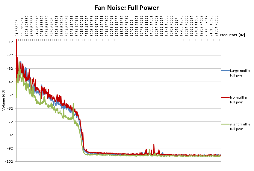
Quieting down noisy ventilation fans
| Details: | Full Power | Half Power |
| I
have been running a 12v DC ducted fan blower, for a few months now, as
the main workhorse of the printer-ventilation system. Its worked out
really well, aside from the noise. At the moment there are two settings
for blower use, a 'low' and 'high' or 50% and 80% duty cycle pwm from a
theta0 motor driver. The noise on 'high' is fairly
loud and the
only way that effectively drowned it out was bad
90's techno.
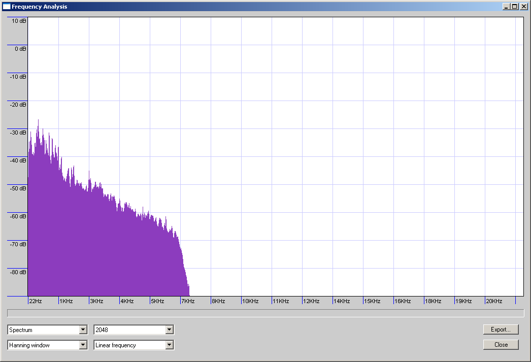
Instead, I gave acousting foam a try. There was a cheap vendor who had some small parts and I performed an amplitude comparison, shown (right). |
 |
 |
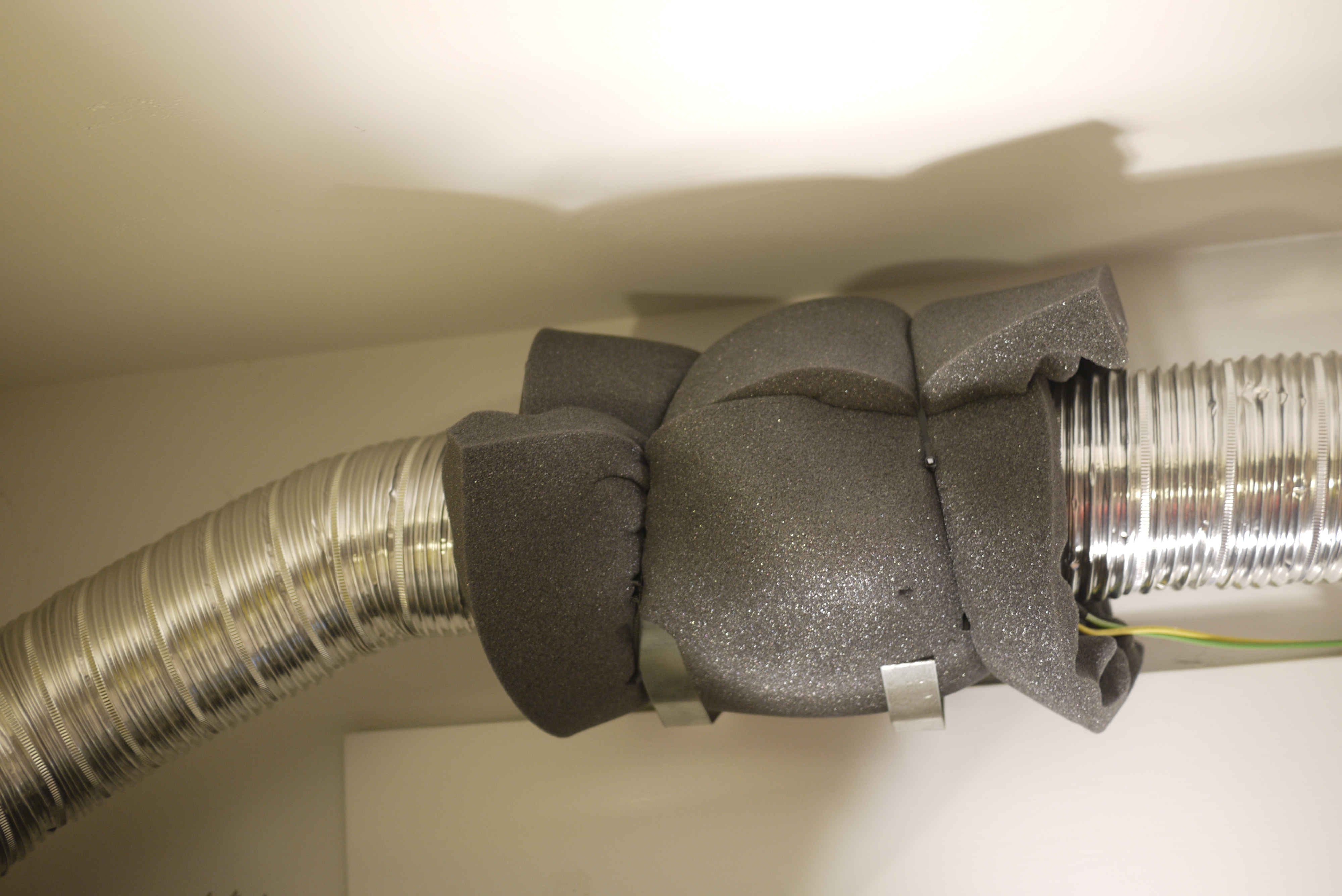
| With and without the eggshell
shroud For a quick test of effectiveness, foam eggshell was wrapped around the dc blower assembly. The eggshell foam was very similar to [link]. The absorption characteristics werent known, so, some quick verification testing was in order. |
 |
 |
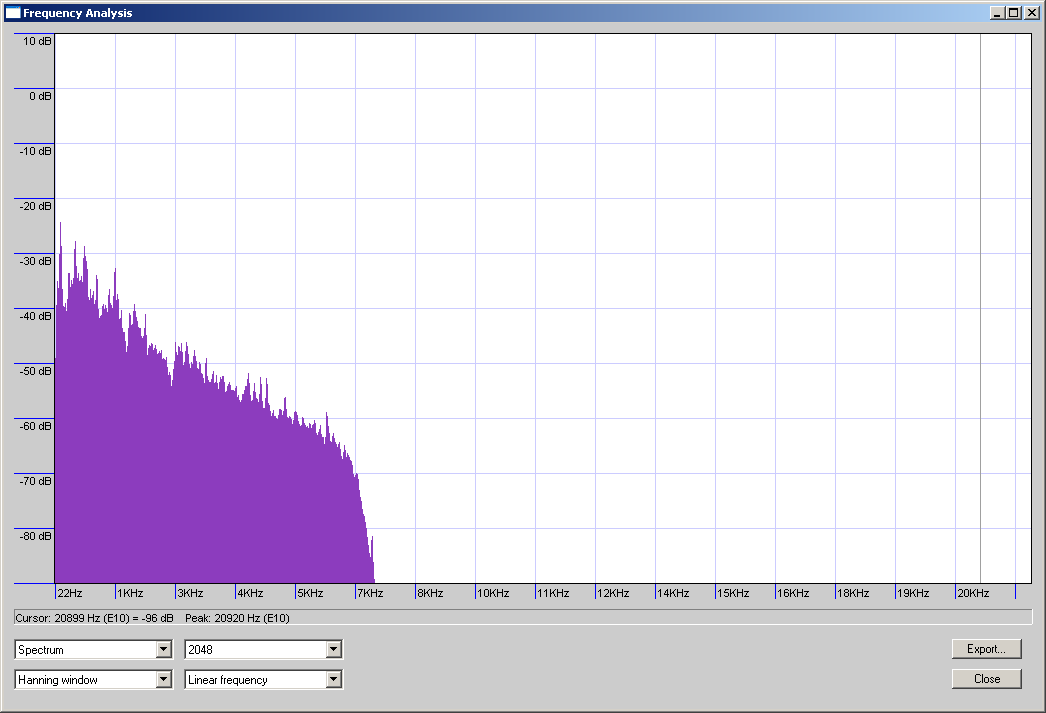
| Looking at the FFT: There wasnt a huge difference between the fully muffled (left) and no muffling (right) from the initial testing. There were small differences between some of the harmonics present across the band, while that spread spectrum absorption follows the characterics of eggshell foam, I was looking for a further amplitude reduction across the spectrum. This pointed toward 'something else' being the cause of the noise. |
 |
 |
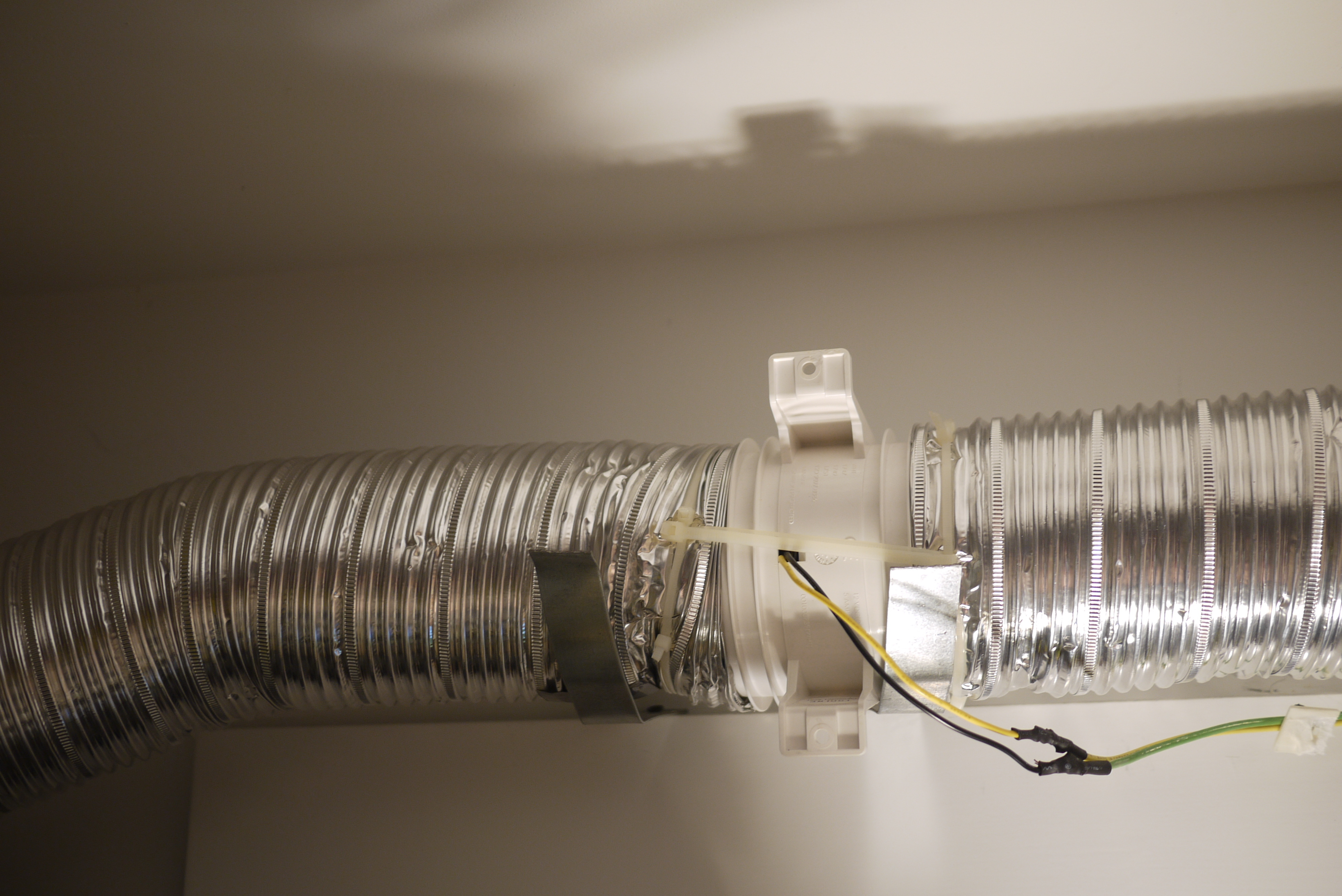
| Ventilation tubing, an antenna
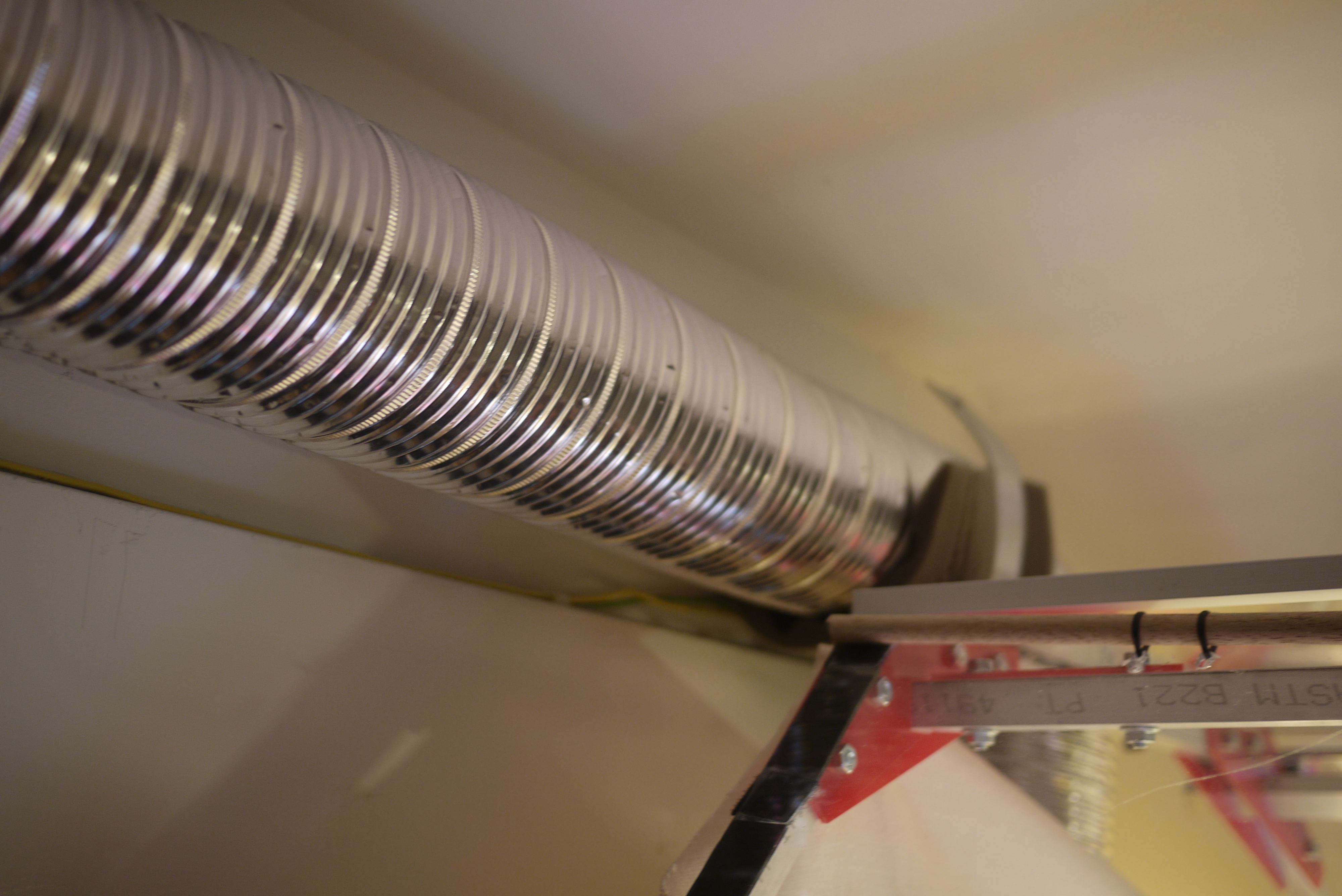
for noise? Adding the foam around the fan assembly has little documented effect (above), however, I quickly noticed that when I applied a hand on the tubing [link], a good majority of the noise was dampened. It appeared that, the cushioned fan assembly was translating vibrations along the flexible duct and using it as an antenna. After adding some foam between the holster (rigidly attached to the wall) and the tubing, a HUGE difference was quickly discernible. It turned out the tubing was coupling vibrations from the DC exhaust fan, and the wall mount was shunting these vibrations, into noise. With the ducting isolated (foam), the issue was mitigated. |
 |
 |
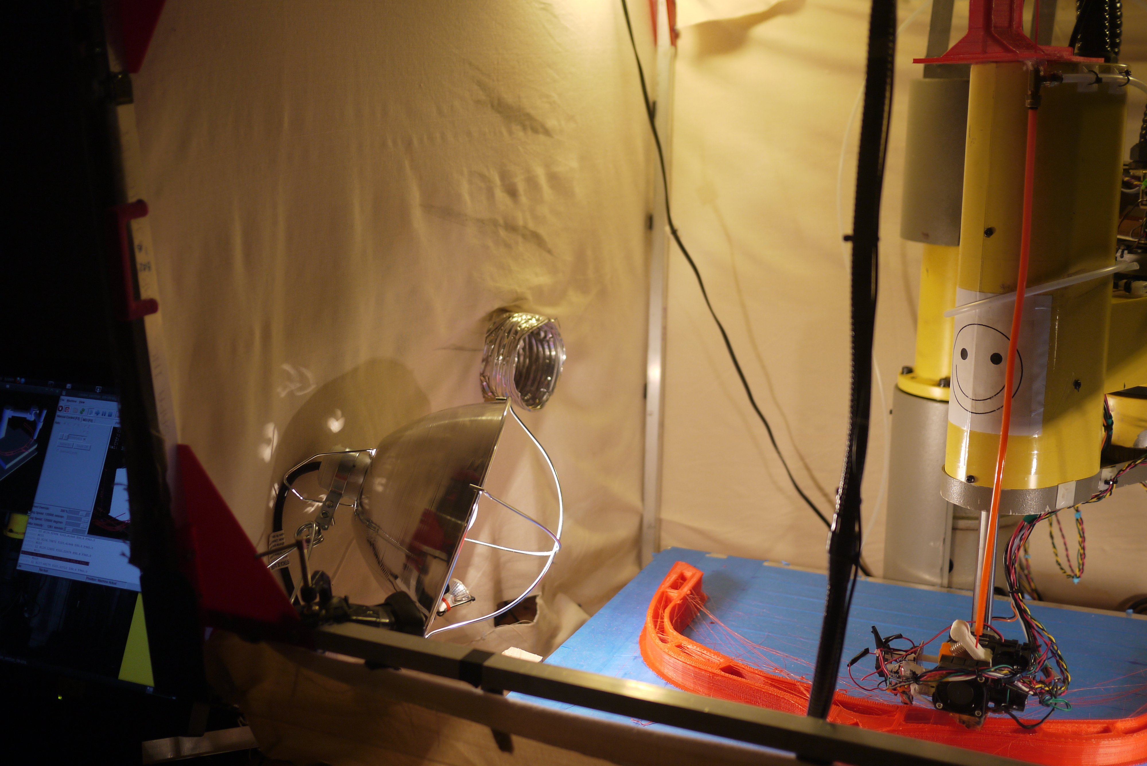
Lights / Heaters
| Details: | ||
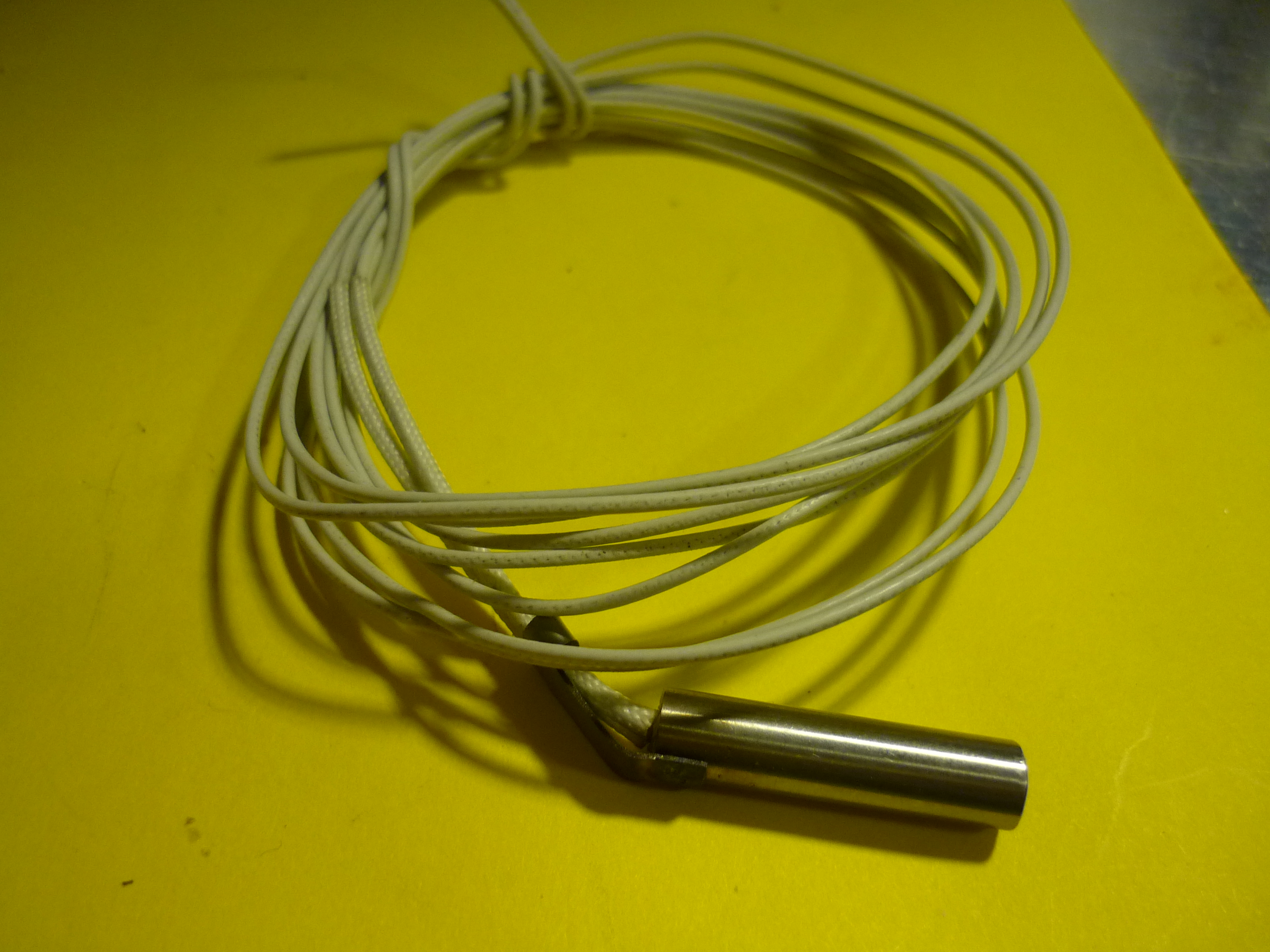
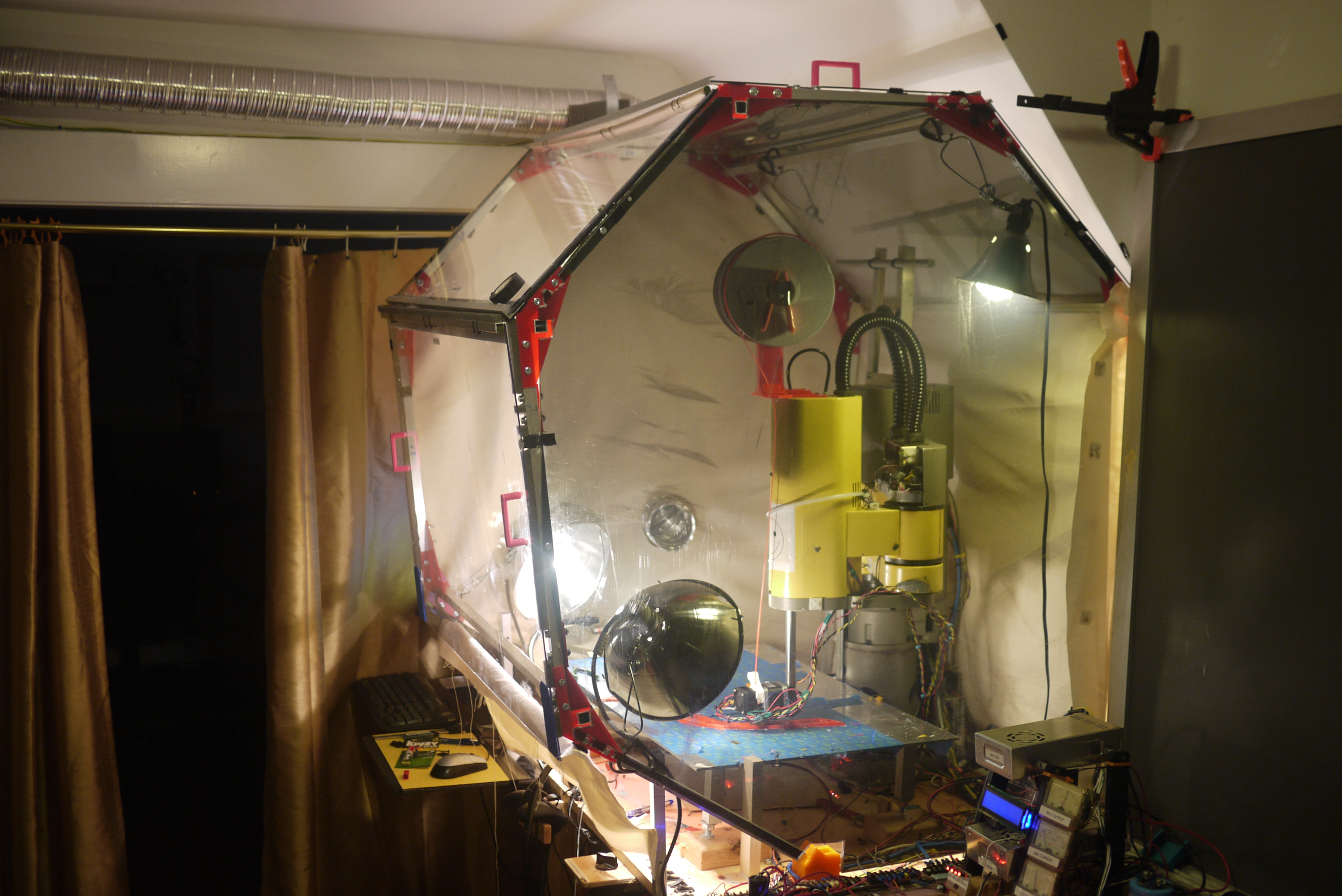
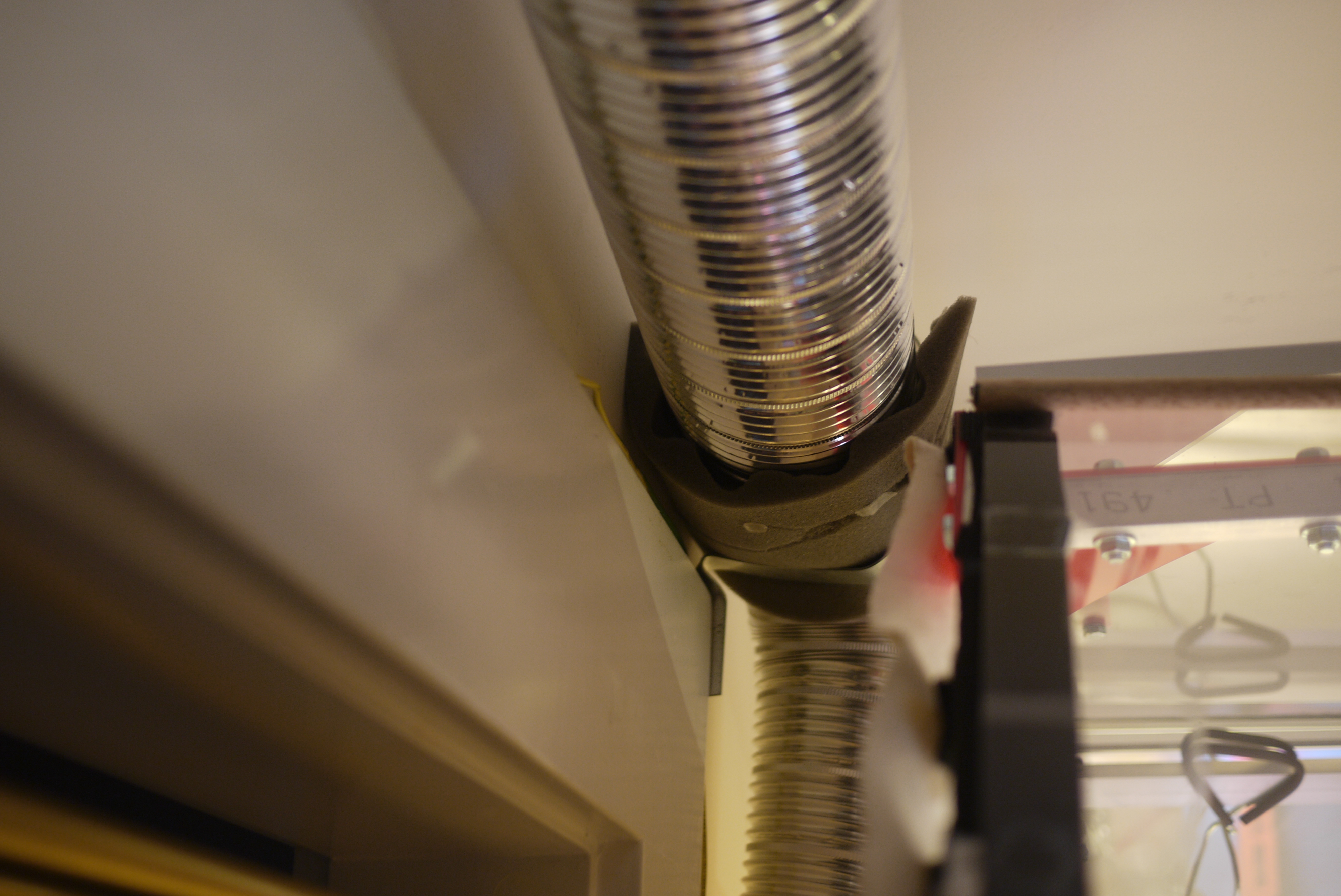
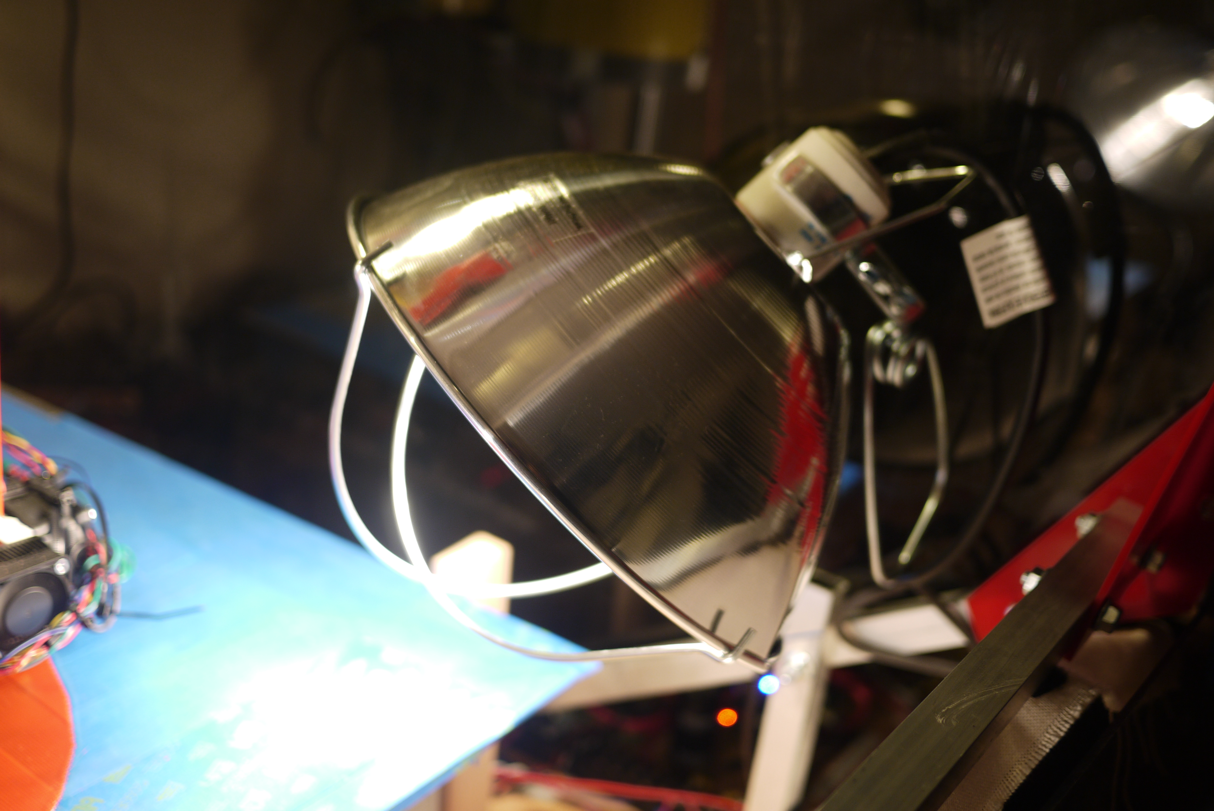
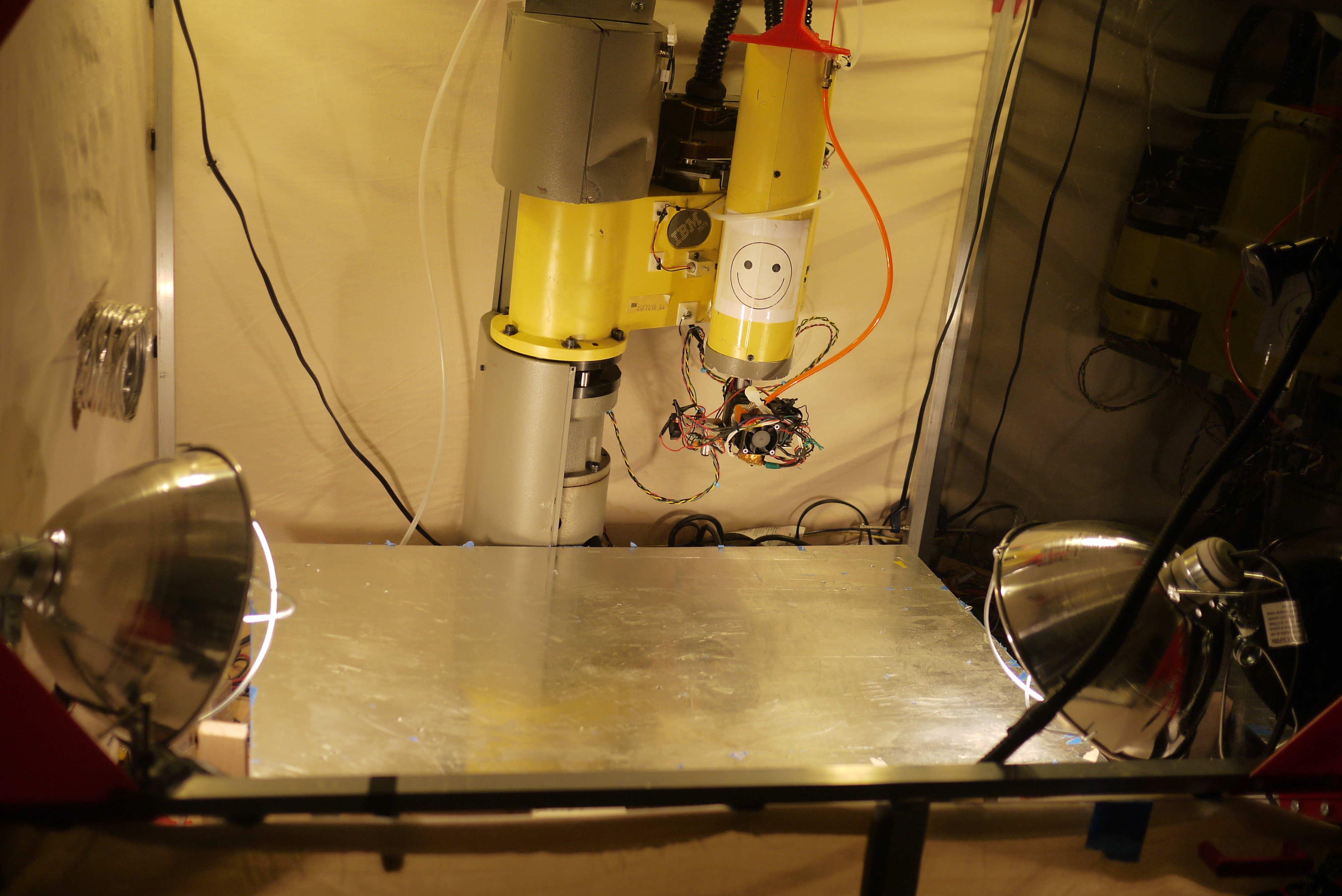
| Inside
the heated build chamber I had mounted two 120vac 'scoop' style lamp
mounts. These holsters can keep ~250W lamps in place, however, I added
in a safety margin of an extra 40% as the chamber would be fairly warm
when operating, and i was not sure what the 250W rating was in
reference to (open air environment? Antarctica?).
I was intending to use the lamps for both light and heat. In total, the
heated build chamber runs 2x 24v 150W heaters and 100W of resistive
block heaters, or ~400W of heat in total. By itself, that warms the
fairly large build platform to ~90C. The goal of the lamps is
to
maintain air temperature and have a portion of the lighting warm the
part (via infrared). The lamp holder is from [here] and the 150W bulb is from [here] |
 |
 |
| Testing
effectiveness One of the advantages of the high power incandescent lighting is radiant heat. While the thin film pad heaters conductively warm up the aluminum heated build platform, the heat quickly dissipates for taller prints The bottom plate temperature sensor was a baseline indicator for the temperature difference. With the heated build chamber in place, and all heaters online, the temperature of the platform hovered around 80C. Using the extra 300W of incandescent lighting, the build chamber temperature monitor approaches 98 C. Unfortunately, accurately measuring the air temperature, in a radiant thermal field is fairly noisy. |
 |
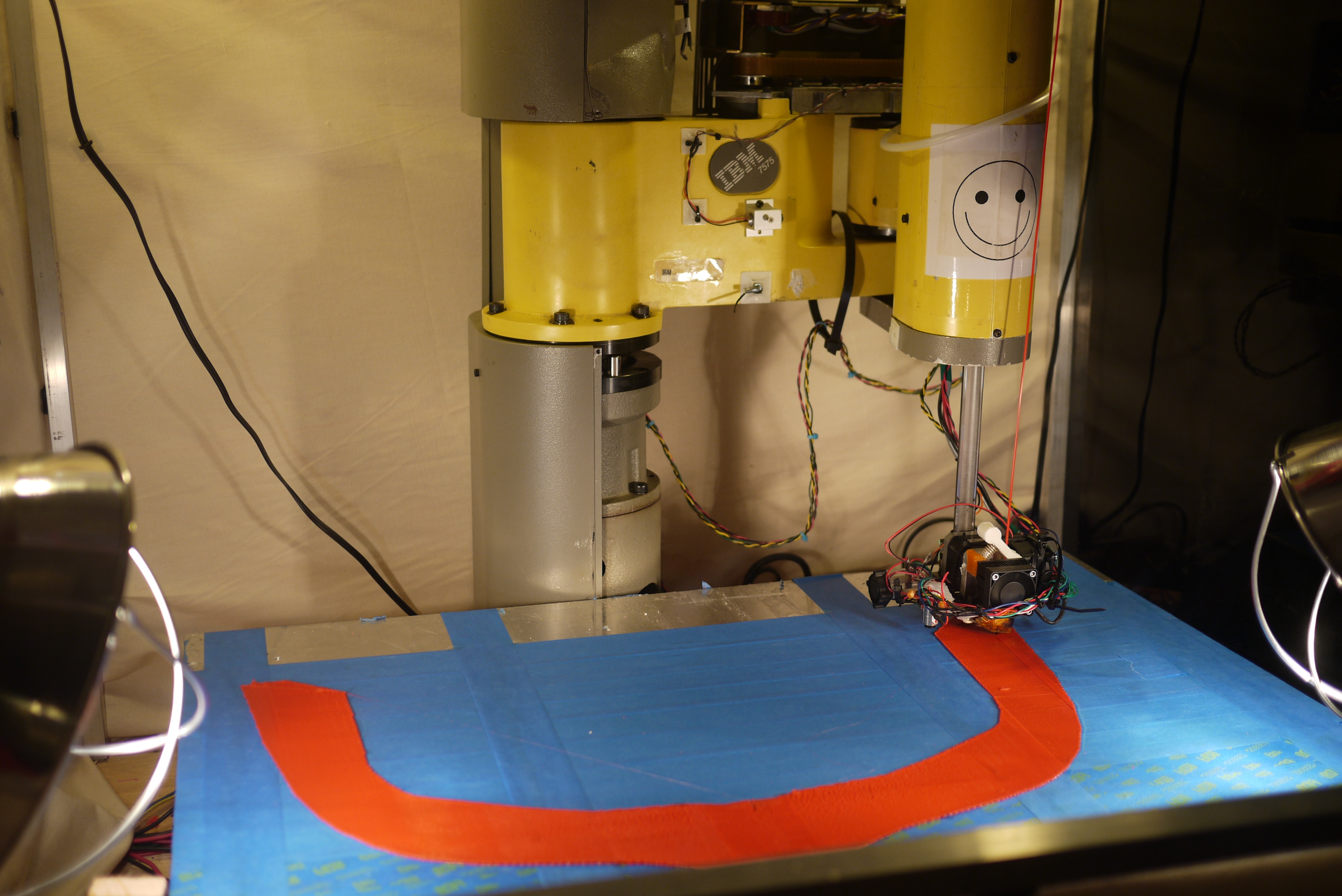 |
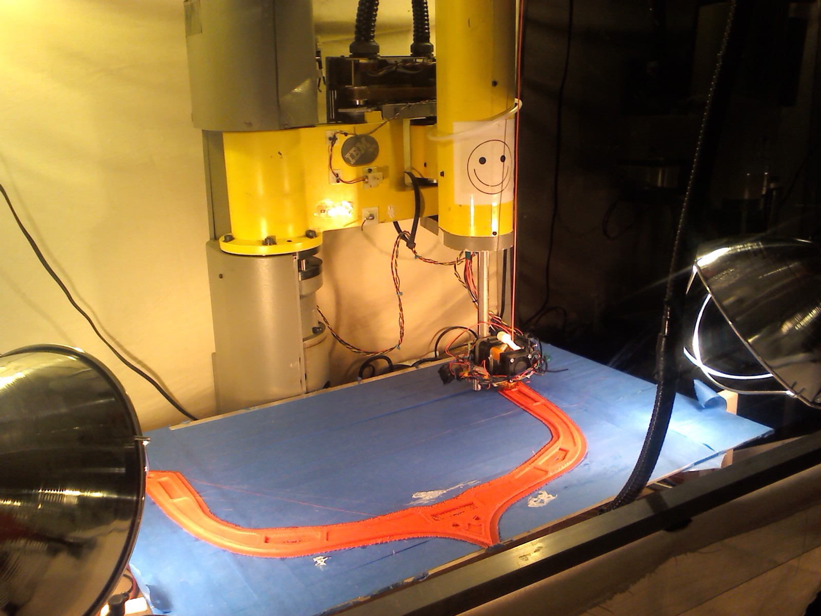
| Less
Raft One of the first things i noticed was how much less rafting was required, initially I printed with the rather rigorous, tall, spacious (wasteful) raft to get the appropriate amount of surface area. After completing the print (canoe hull test piece) i was able to change the parameters in skeinforge to remove a layer of the raft and reduce the edge barrier size, shown right. |
 |
|
Baseplate Material Research
| Details: | ||
| Background ABS doesn't stick well to a bare metal platform, and if it did it would be fairly difficult to remove, so an intermediate layer is used. The intermediate layer acts as a bonding agent, tying the main ABS print to the heated platform. Its a bit of a balance, as you want the intermediate layer to stick to the platform as well as the printed part, yet be removable. The intermediate layer needs to have enough surface area to allow for a strong contact. Apparently few folks have the issue of their baseplate de-laminating from their build platform. Its not very often blue painters tape pulls off, or kapton tape peels back from smaller makerbot / solidoodles, but it really starts to appear in larger build platforms. The thermal warping should be directly proportional to contact surface area. Consider the following: some of the larger prints on the robot exceed 50 square inches of base contact area, then proceed to tower 9" above the platform. There's unfortunately alot of room for thermal gradients, even with the heated build chamber and hot air. Due to the coefficient of thermal expansion of ABS 73.8 (10-6 m/m K) *) [link], the only real work around is not trying to defeat physics and heat up everything. Which is why this was born. |
 |
 |
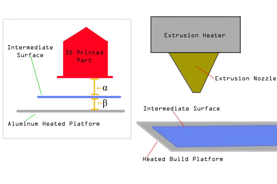
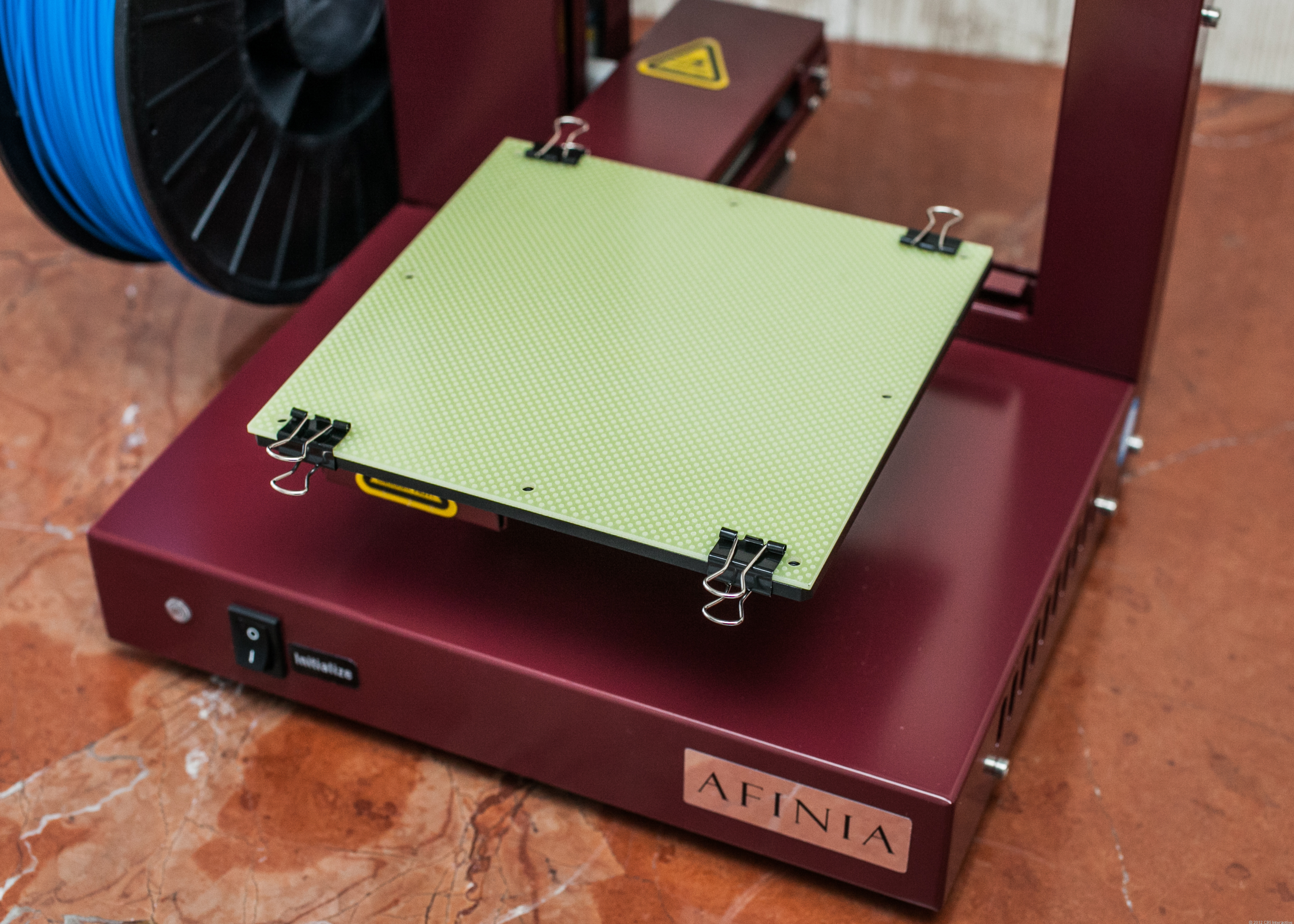
| Intermediate
baseplate material? The need for an intermediate layer roots from the bond between ABS and my bare aluminum heated build platform. Unfortunately/fortunately something with a higher-surface area and a better bonding characteristic is necessary. The choice for that material is based on two bonding criteria and a coeficent of thermal expansion. Shown (right) the bond between the 3d printed part and the intermediate surface (α) needs to be large enough that during the print the part does not de-laminate or peel off, yet low enough that it is removable when the part is complete. Next the bond between the build platform and the intermediate material (β)needs to be greater than (α), so that it does not pull itself from the platform. An interesting alternative to 'tape' is a removable mechanical connection, shown (right) [up! 3d printer image from cnet] |
 |
 |
| Blue Painters Tape Blue painters tape has been my go-to intermediate layer, it sticks fairly well to the aluminum heated build platform, ABS sticks to it fairly well, and super glue / cyanno acrylate does nicely to bond the two together. I started using blue tape on day one, the only reason I looked for alternatives was to get around the need for copious amounts of CA glue. At high temperatures (90C build platform) the adhesive on the blue painters tape starts to become soft and delaminate from the heated platform. |
 |
 |
| KAPTON tape Kapton is a really interesting material, that I only recently started using. While the makerbot folks have moved towards using it as their defacto bed material on the replicator 2, I had mixed success in my application. There were a few issues, namely, even with a heated platform and close tolerances, ABS does not appear to stick nearly as well, without significant CA glue application. With CA, the kapton has the benefit of its extremely good bonding to the heated build platform, so it tends not to pull away from the platform as much as painters tape does. |
 |
 |
| Sliced up Acrylic Sheet The build platform needs a few things to work well, a decent bonding with the work material (ABS), a low cost, and enough rigity to maintain its shape during thermal stresses. I took a sheet of scrap 0.22" thick 4' x 3' acrylic plastic and lasercut it using a 0.25" grid. By setting the power level and speed of the lasercutter, I was able to have a small etch, with plenty of surface area for the 3d printed part to stick to. The issues i ran into with this approach was namely the part either sticking too well, or the acrylic itself warping upwards while sitting on the heated build platform. The acrylic sheet was a bit expensive to replace, however worked well for small and large prints. I will suggest increasing the grid size from 0.25" square to something higher to reduce the contact surface area. |
 |
 |
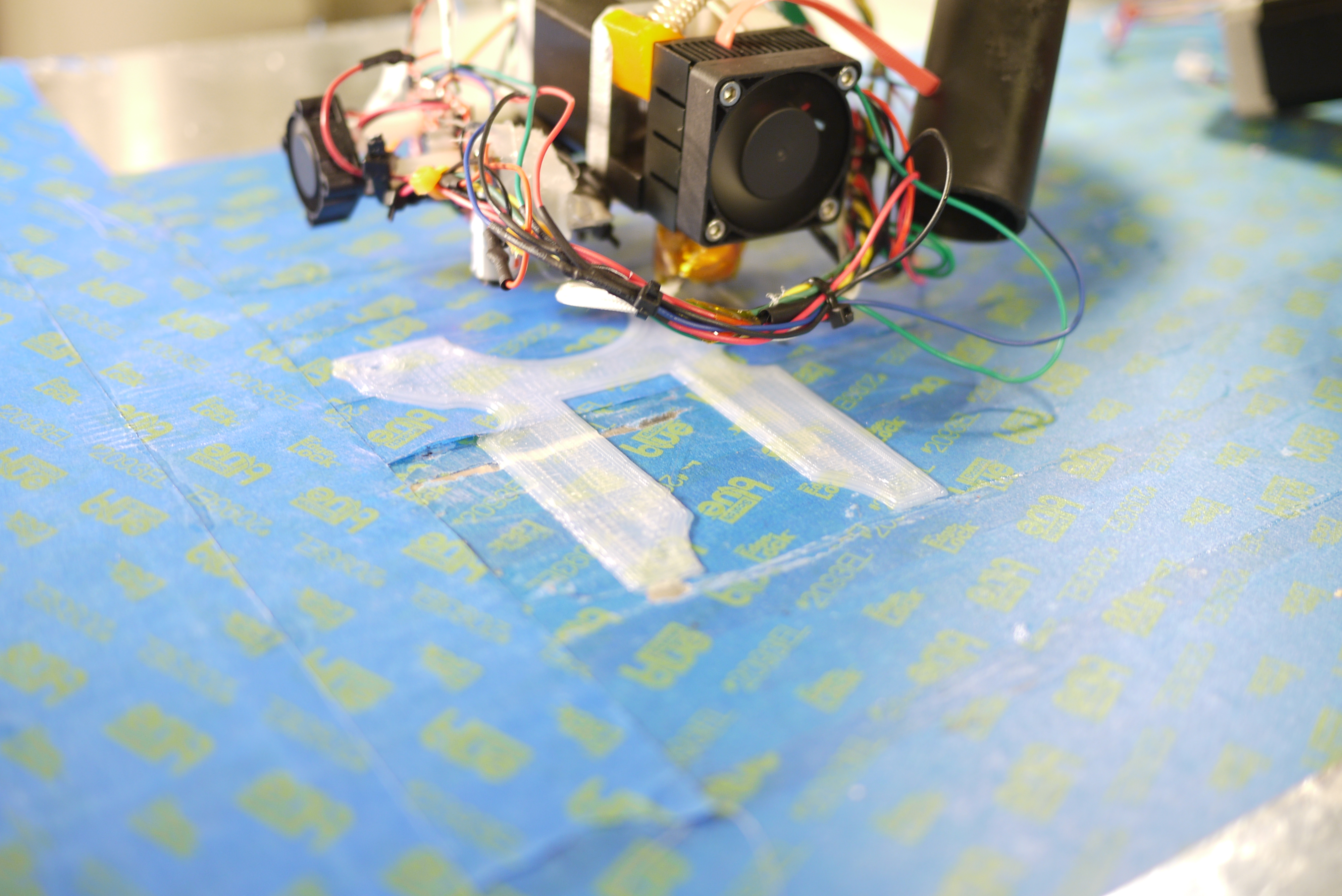
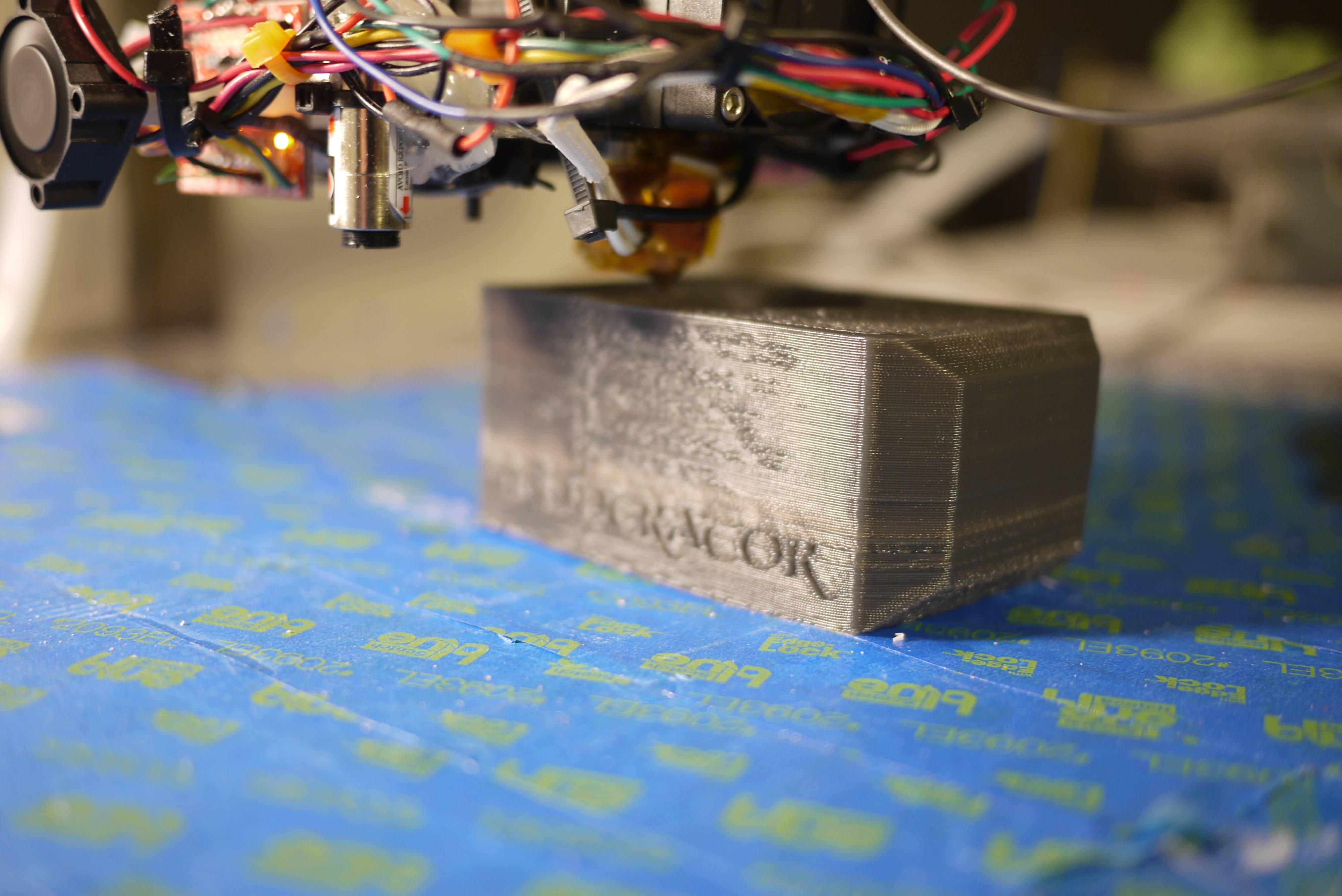
| ABS
sheet Did you know 1/8" thick ABS sheetstock exists [link]. I was able to purchase a 4' x 2' sheet and jigsaw-cut it to shape for the heated build platform. My logic is as follows: printed ABS should bond / fuse well with cast ABS, the coeficient of thermal expansion should be very similar, if not identical, and mechanically constraining / reinforcing ABS should be straightforward. Its flexible enough to 'bend' and remove 3d printed parts, yet should have the right amount of surface area for contact. Realistically, the ABS does flex a lot, and bond VERY well to the print, making it fairly difficult to remove. As a result, difficult to remove remnants |
 |
 |
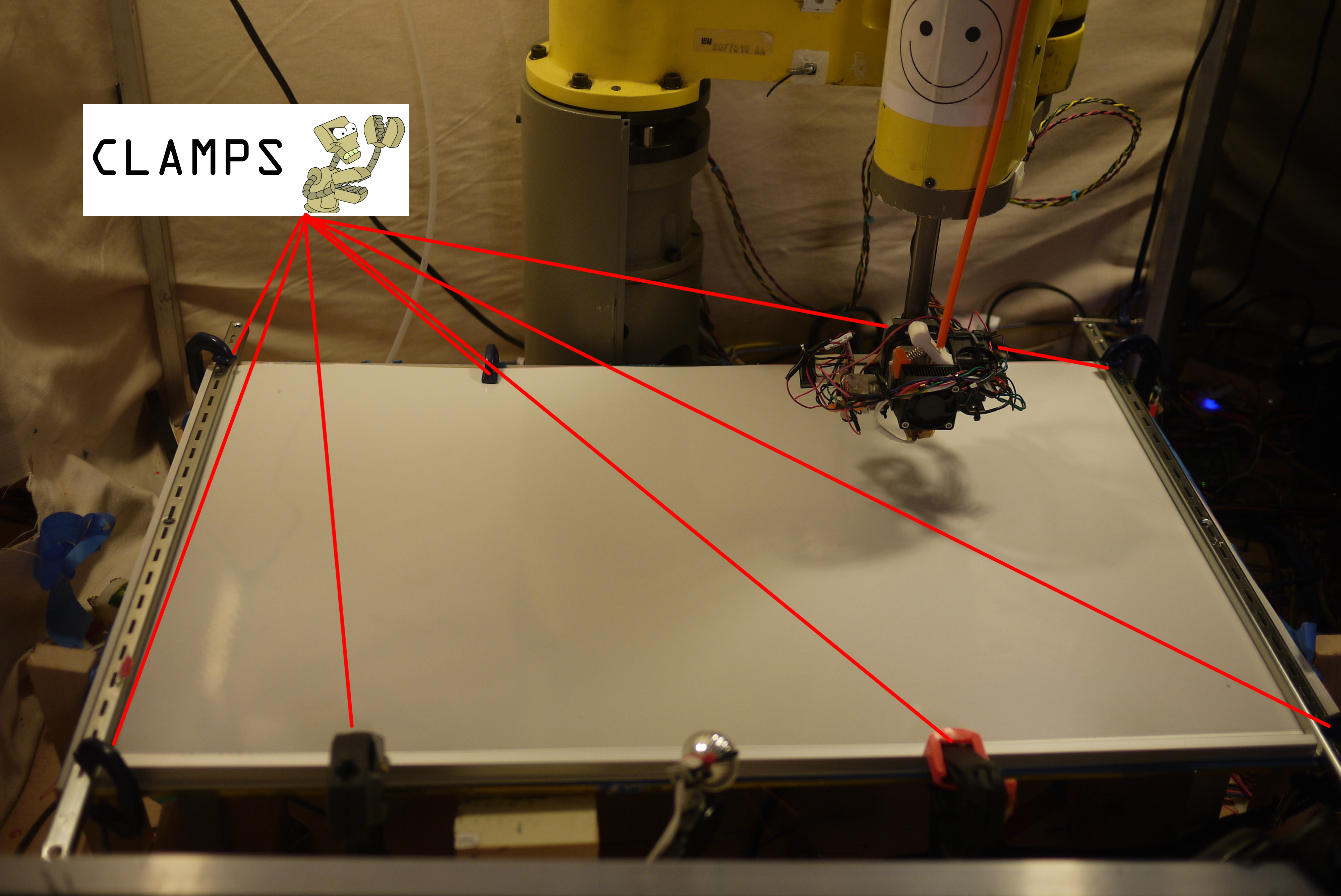
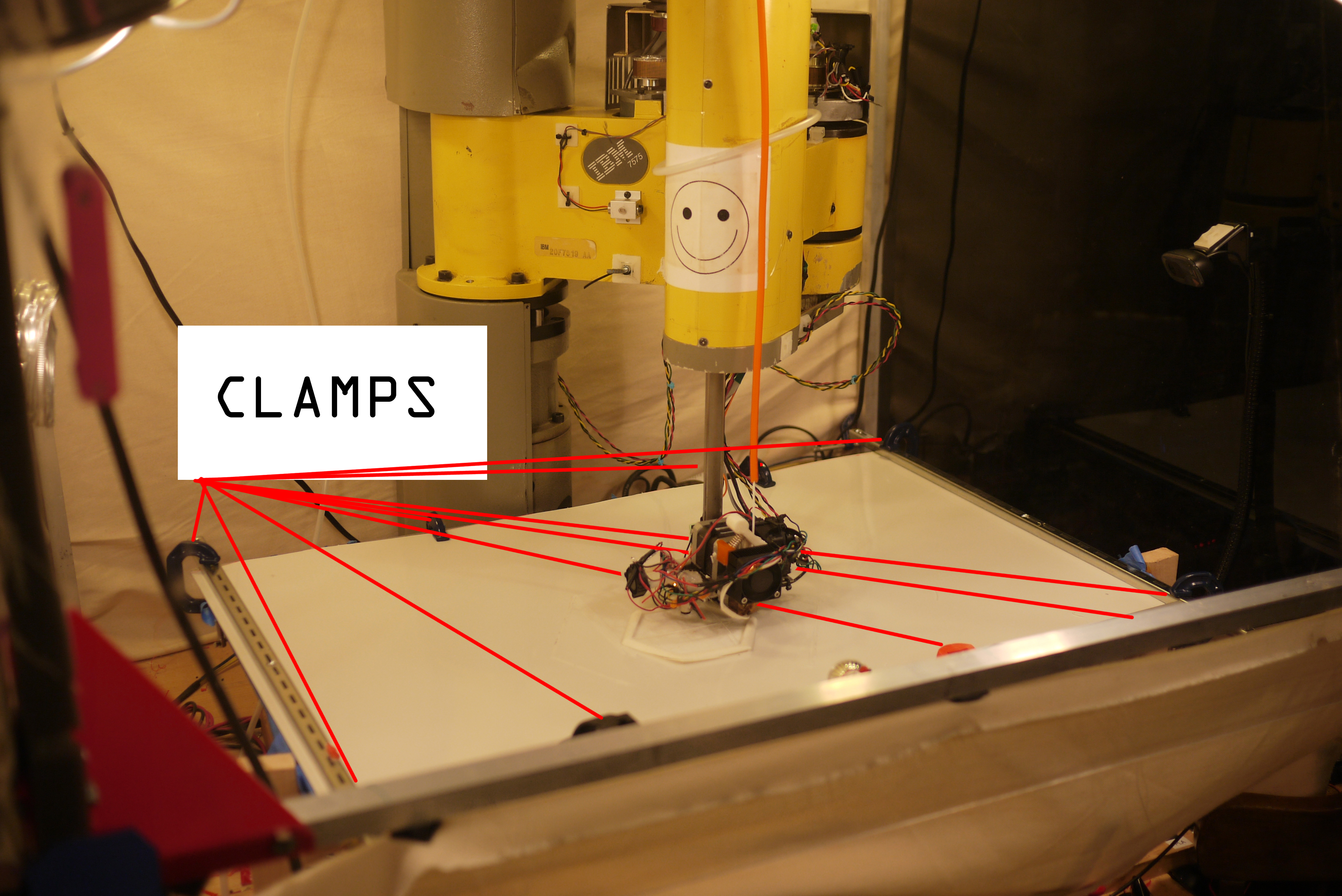
| Securing
the ABS sheet Like anything else, the ABS sheet expands and contracts, causing it to sneak away from the build platform. I was able to get around this issue by allowing the ABS sheet to get up to temperature (with the build platform on high), then clamp it in place using 4 'tiny c-clamps' and two long metal shelf brackets. |
 |
 |
Variable Speed Extrusion rates, tied into linux CNC
| Details: |
| For
the whole time I've used the machine, I have been running
(surprisingly)
fixed extrusion rates. Yep, thats right, the robot ignores
the
end of the M-code to extrude at a set speed and goes at an extrusion
rate defined by a small potentiometer, labeled 'manual extrusion
control'. I've been meaning to fix this, however, its been working
reasonably well, so, it fell to a lower priority. When instructing the
printer to 'extrude' there are two M-Codes used M101 and M108.
M108 sets the extrusion motor speed, M101 enables the
motor. M102 disables. At the moment, I have M101/102
instructing
the extruder to turn on or off, blatantly
ignoring the M108 extrusion speed setting. This causes a
few undesirable effects, namely on the edges of prints. |
| Given that the robot needs to abide by physics, it hits a maximum and minimum acceleration software limit when changing directions. As noted above, corners are the first issue that comes up with fixed extrusion rates.The machine must de-celebrate into a corner and then re-celebrate after the corner. This reduced velocity, with a constant extrusion rate, results in excessive printer buildup on these slow areas. |
| Time
for some upgrades As I'm not presently using any standard hardware, communicating from the m-codes to an external stepper drive from a pc is a bit more involved. In this instance, every time an M108 code happens, it triggers a sub-routine, much like I used initially on the 'bang-bang' extrusion technique [link]. As I did not want this operation to result in any increased system latency, I did the simplest thing possible, the M108 opens /dev/ttyUSB0 and yells out the percentage speed at 115200 baud over rs232. The stepper driver, which is based on the trusty theta0 controller, then interprets this and spits adjusts the extrusion rate accordingly. |
Extruder Jamming: Cooling down the filament using aquarium parts, surplus tubing and Harbor Freight
| Details: | ||
| One of the quirks with a
heated-build-environment is that everything
becomes rather warm
including the ABS filament. Prior to designing the heated build
chamber, the only items I was concerned with was 'how can I keep all
this air and space warm?'. The motors and cabling were all rated for
temperature, but the filament, which purposely softens at 70-80C, can
become troublesome for the extruder. The softer the plastic, the more
the extrusion gear chews into the plastic under any loading. As a
result 'chew marks' occur. After the extrusions chew passes ~80% of the
thickness of the filament, it will no longer extrude and, the print
will be missing significant area unless caught early. |
 |
 |
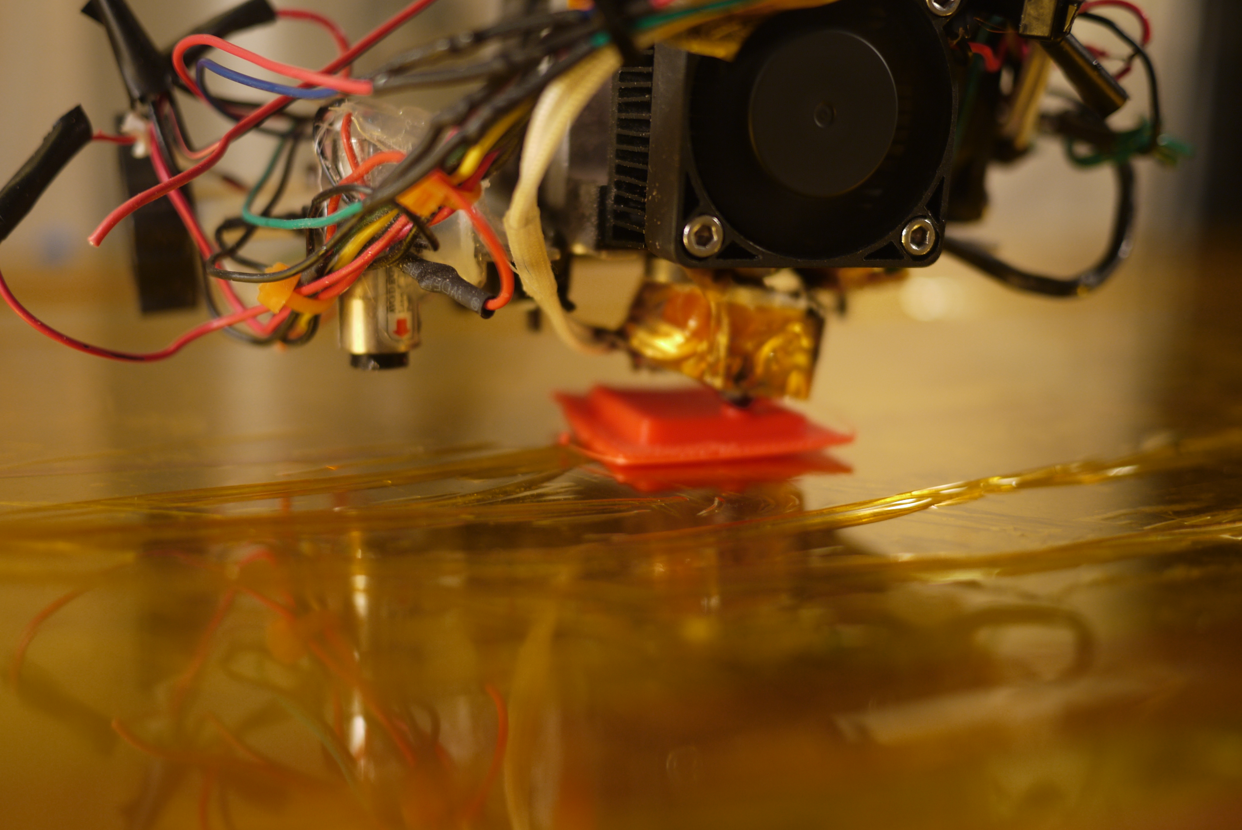
| Given the potential root-cause of the issue is the ABS / PLA feed being too warm, my first solution was to pipe in room-temperature air to keep the filament cool. To do this i used a 24v compressor and some 6mm nylon tubestock with an opening to allow for the tube-filament feedthrough. Note this was a 'quick test' to determine if it was a feasible option. It turns out, IT IS, its actually similar to what stratasys does in some of the more industrial machines, found from haveblue's blog [link] | 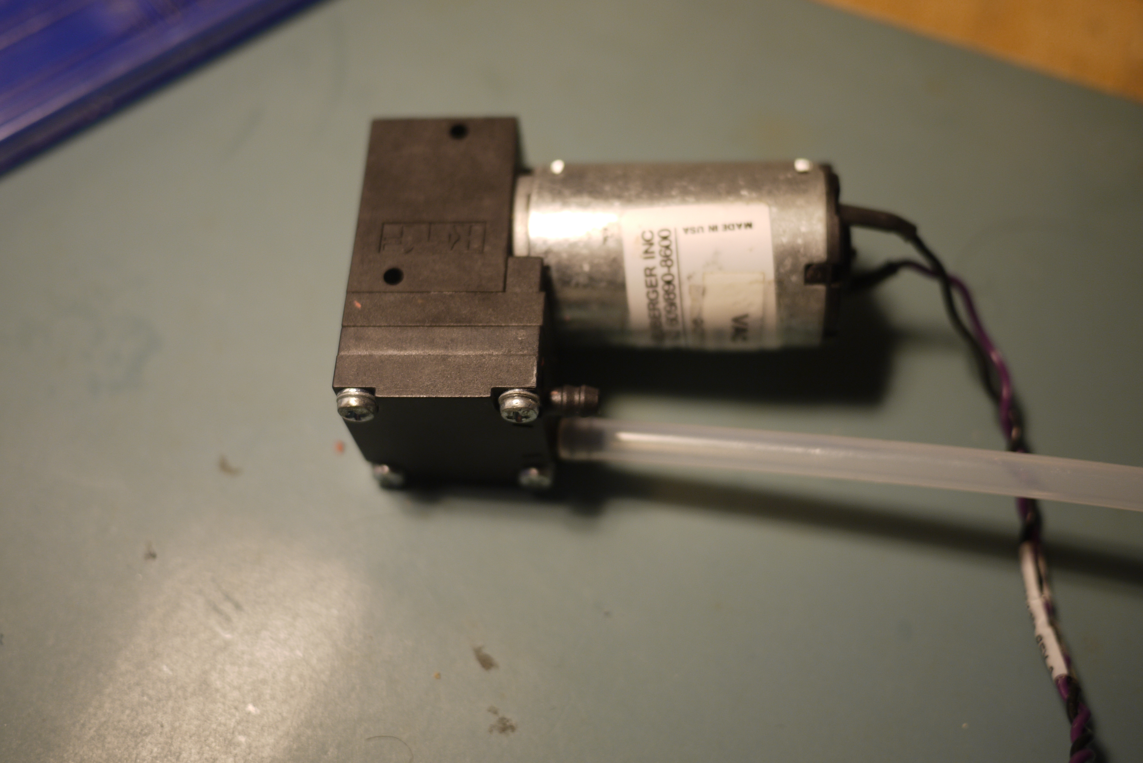 |
 |
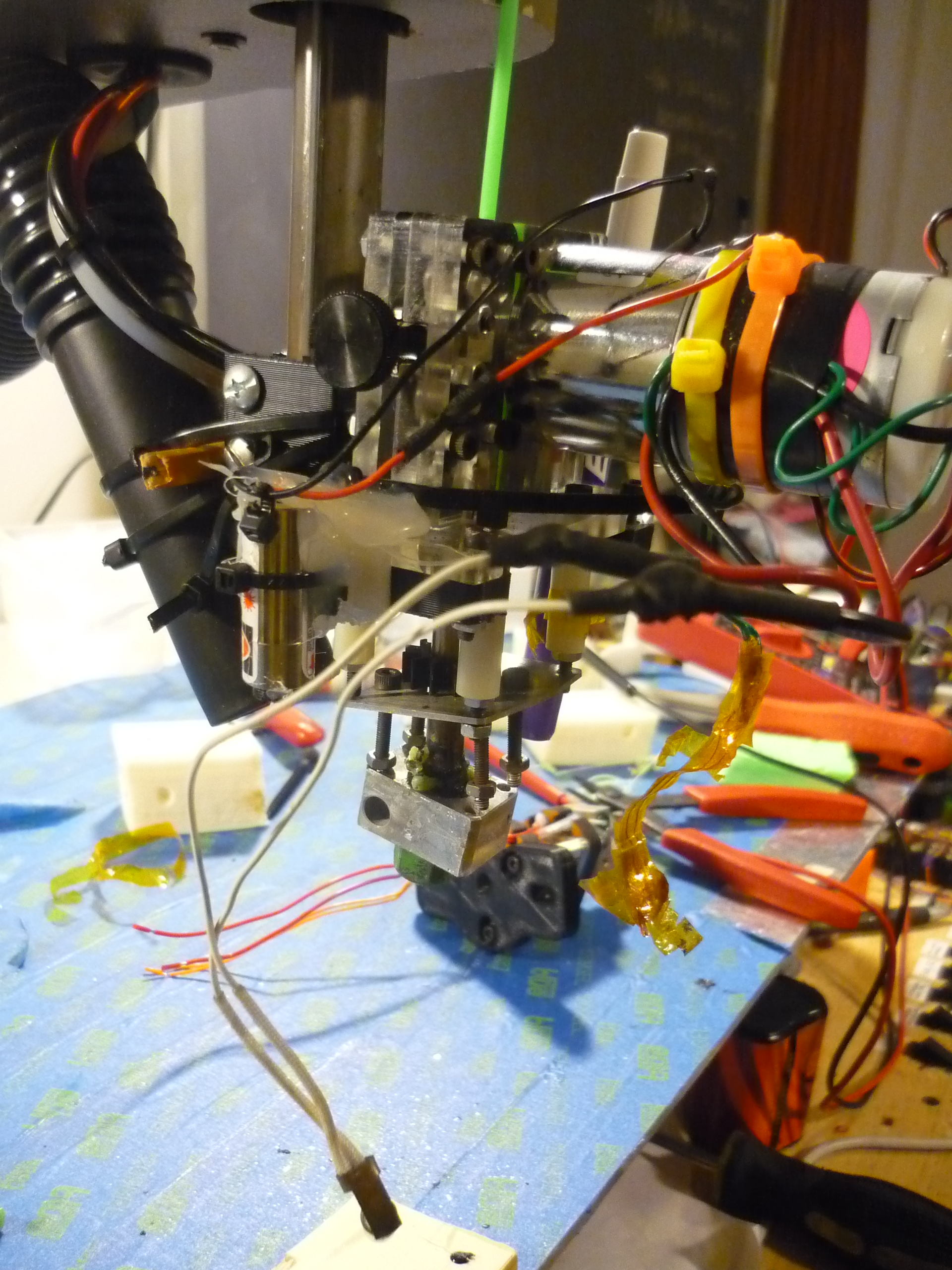
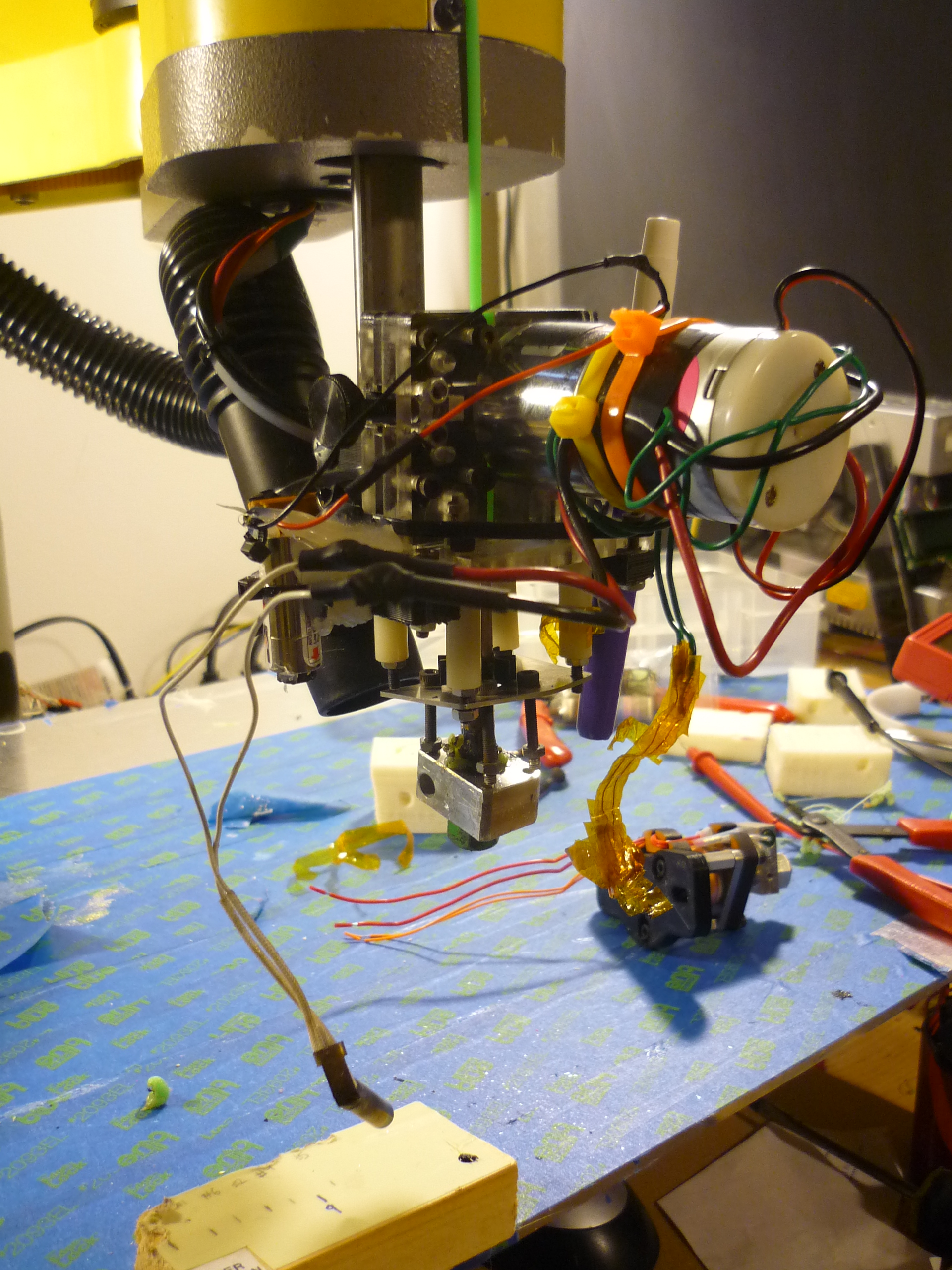
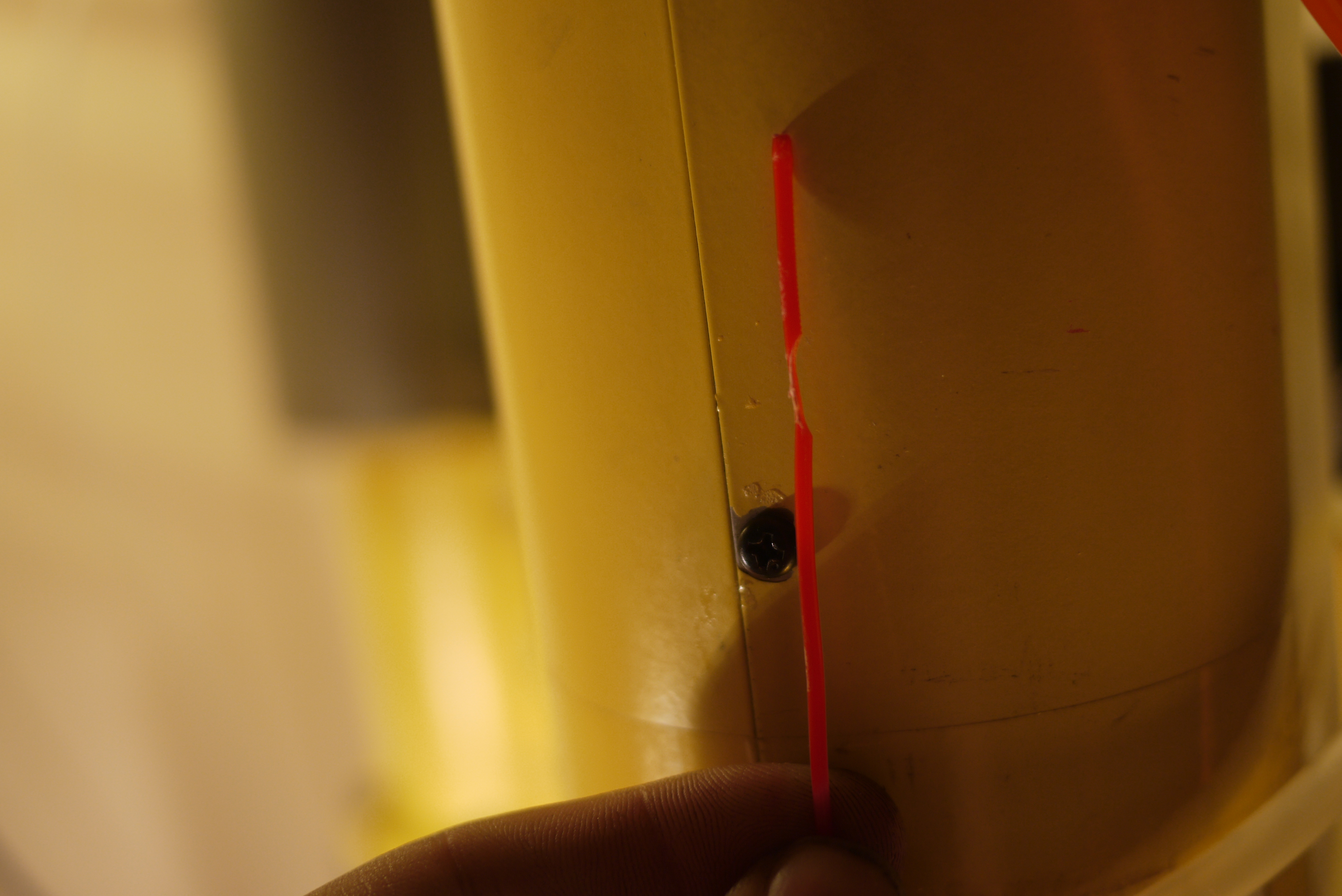
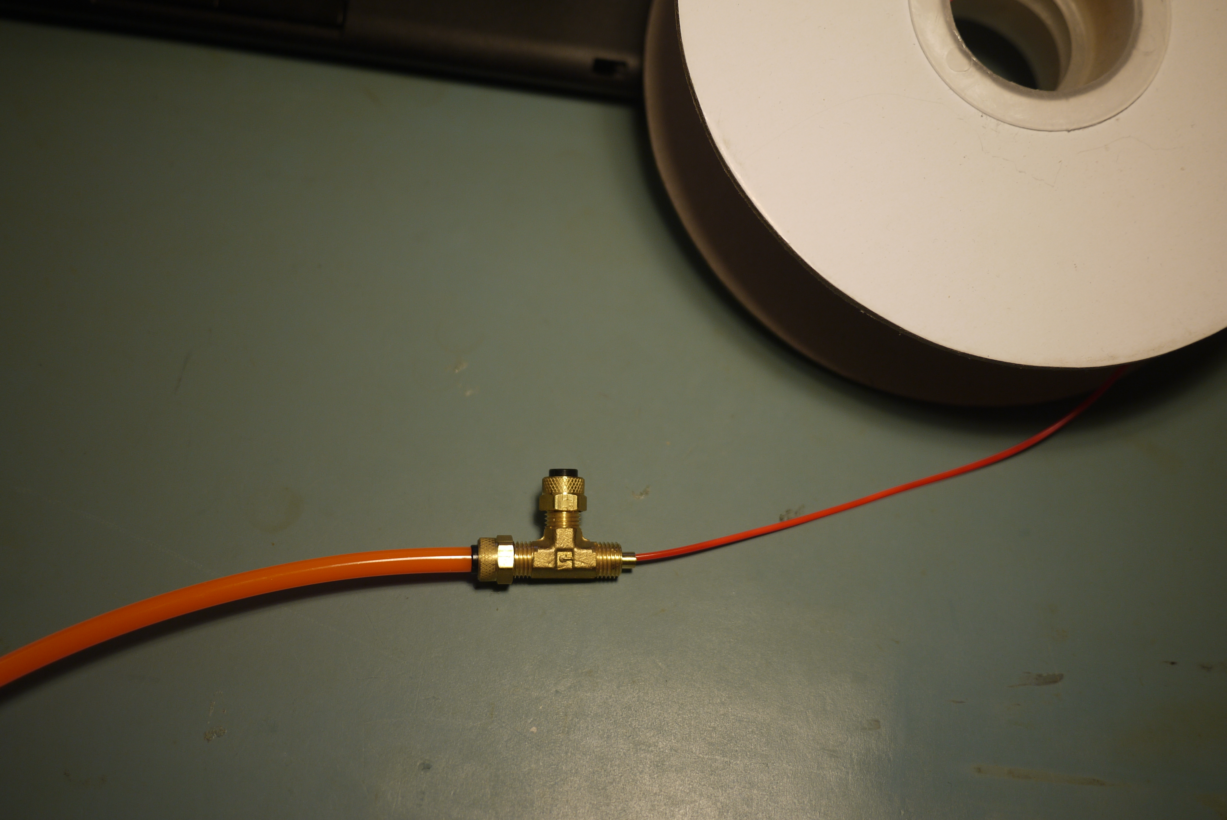
| Time
for some upgrades I needed an interface between the air system and the inbound plastic, this T-coupling worked swimmingly. Shown, right, is the coupling, with the first compression nut and ferrel removed, and the corresponding path has 6mm nylon tubing attached. |
 |
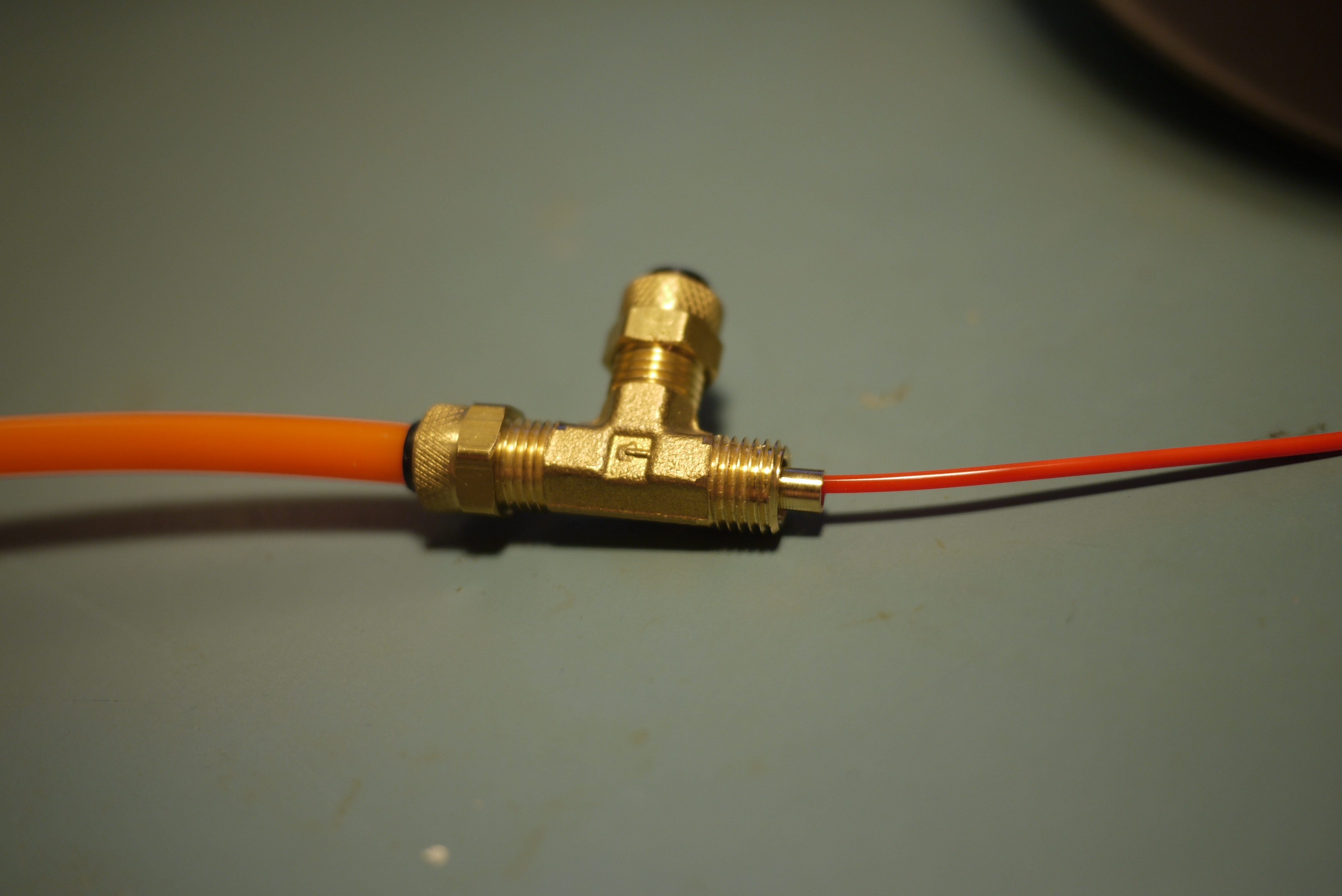 |
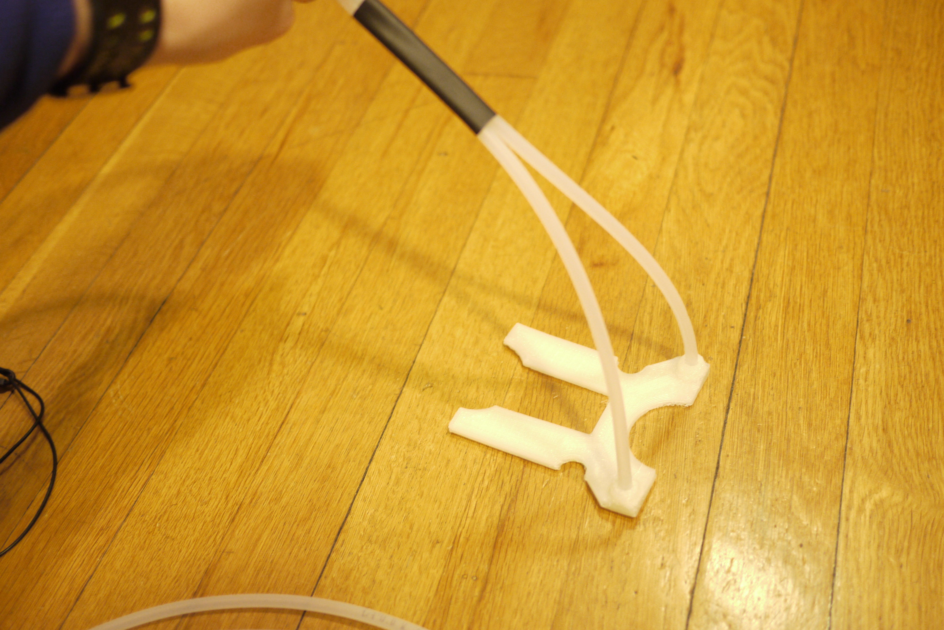
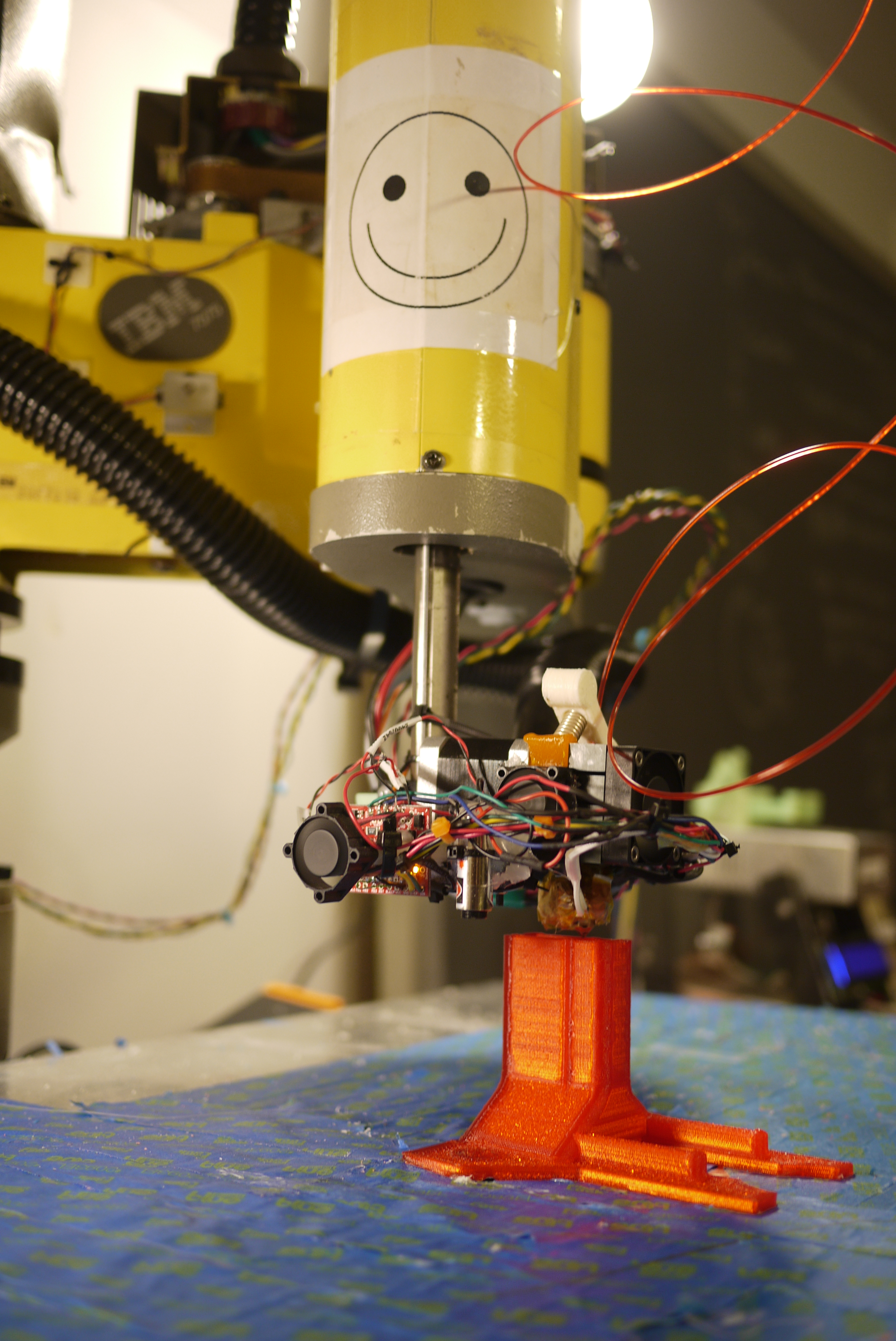
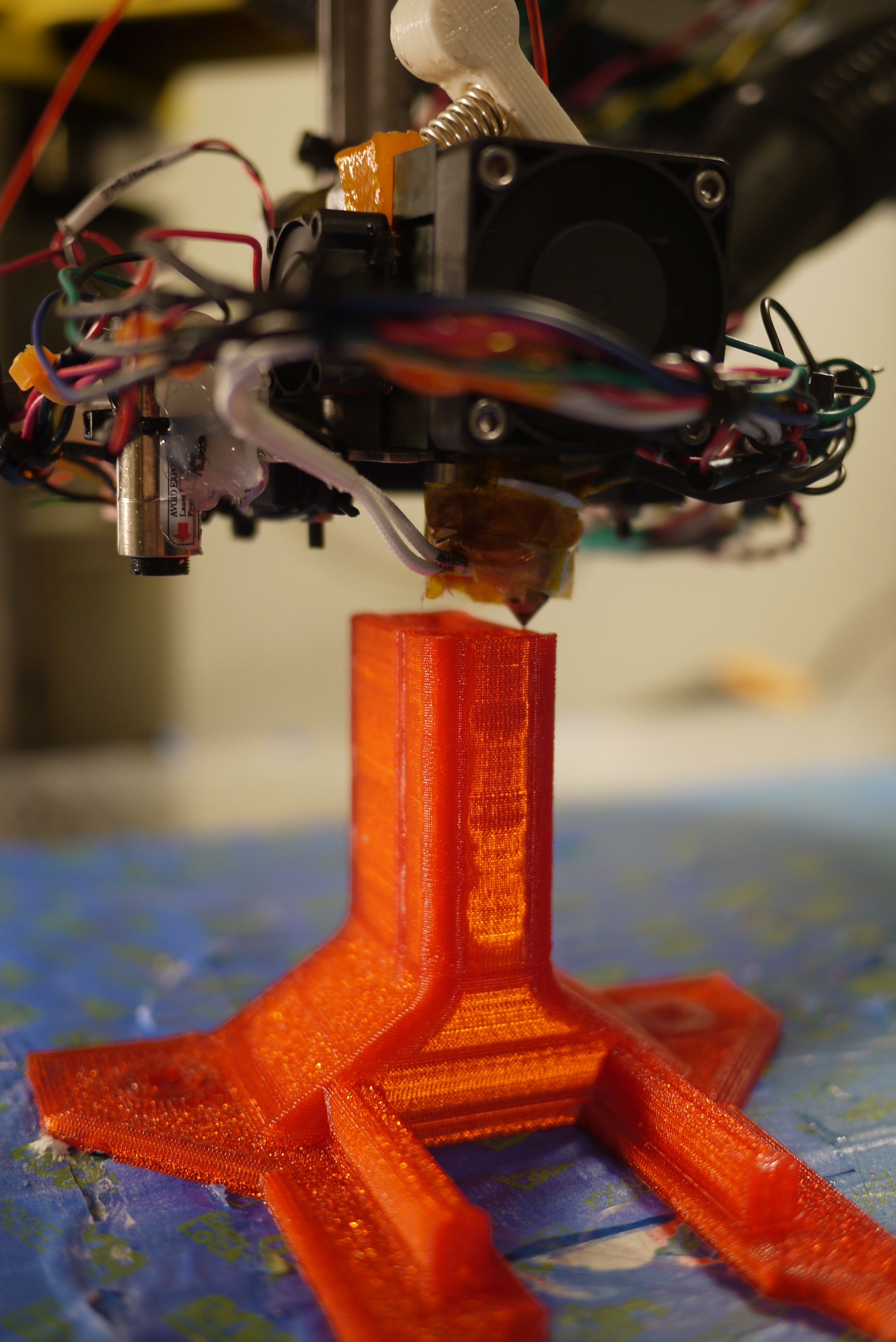
| A
Rather Fantastic T-Coupling I must admit, the idea to use a T-coupling, one almost perfectly sized for this function, was not my own. A rather excellent co-worker pointed out the similarity in sizing of the ferrel-interface. The benefit of this setup is that cooled air, piped in through the translucent tubing, mates with the 1.75mm ABS feed, and the protruding path from the spool to the extruder (orange nyol tubing). During this transit, the ABS is kept cool by the forced air, allowing it to stay well below its glass transition temperature. The small size of the ferrel opening results in less compressed air being wasted through the top, and more piped through the bottom. I can estimate. from observation, that at least 40% of the inbound airstream exits through the base of the orange nylon tubing. |
 |
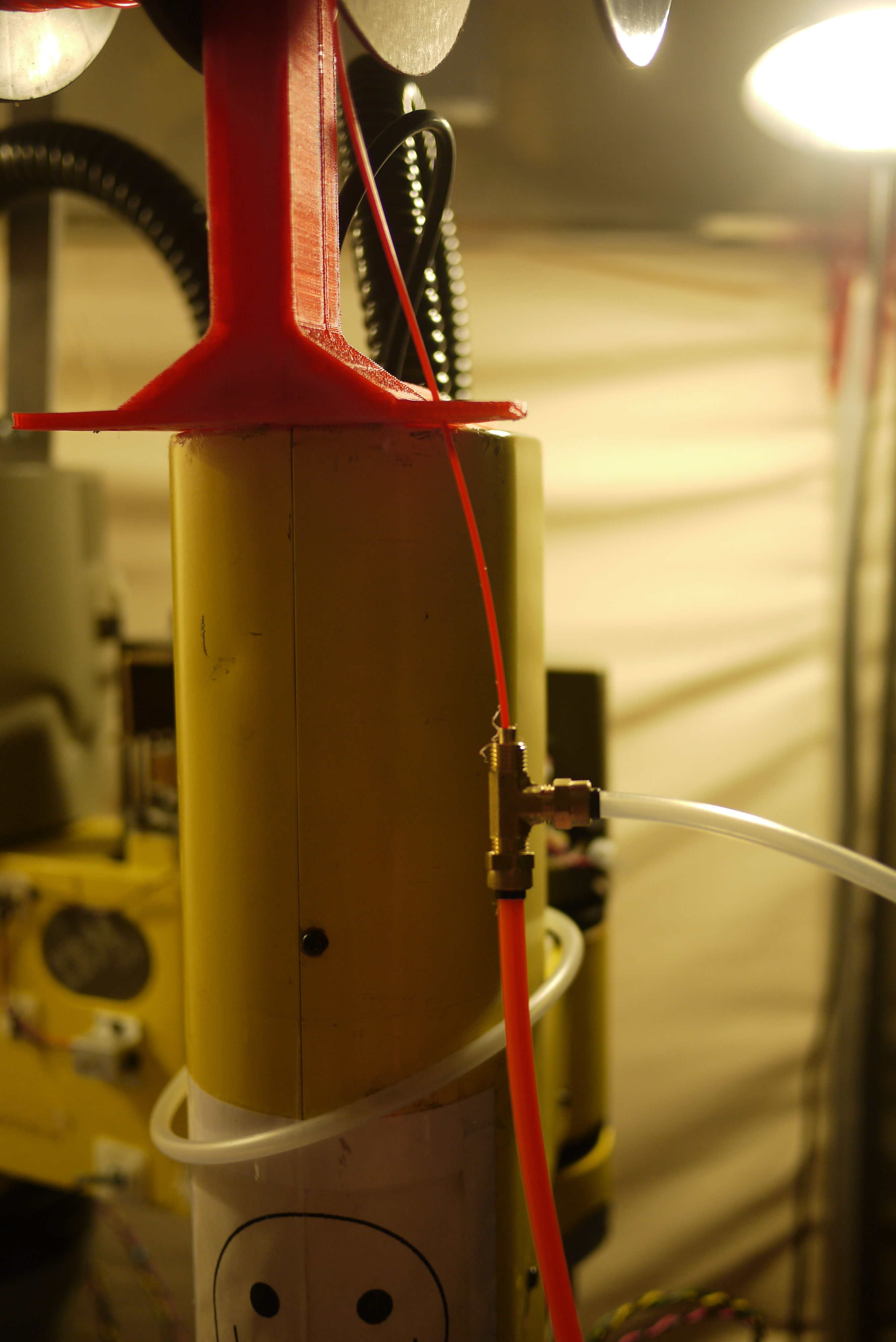 |
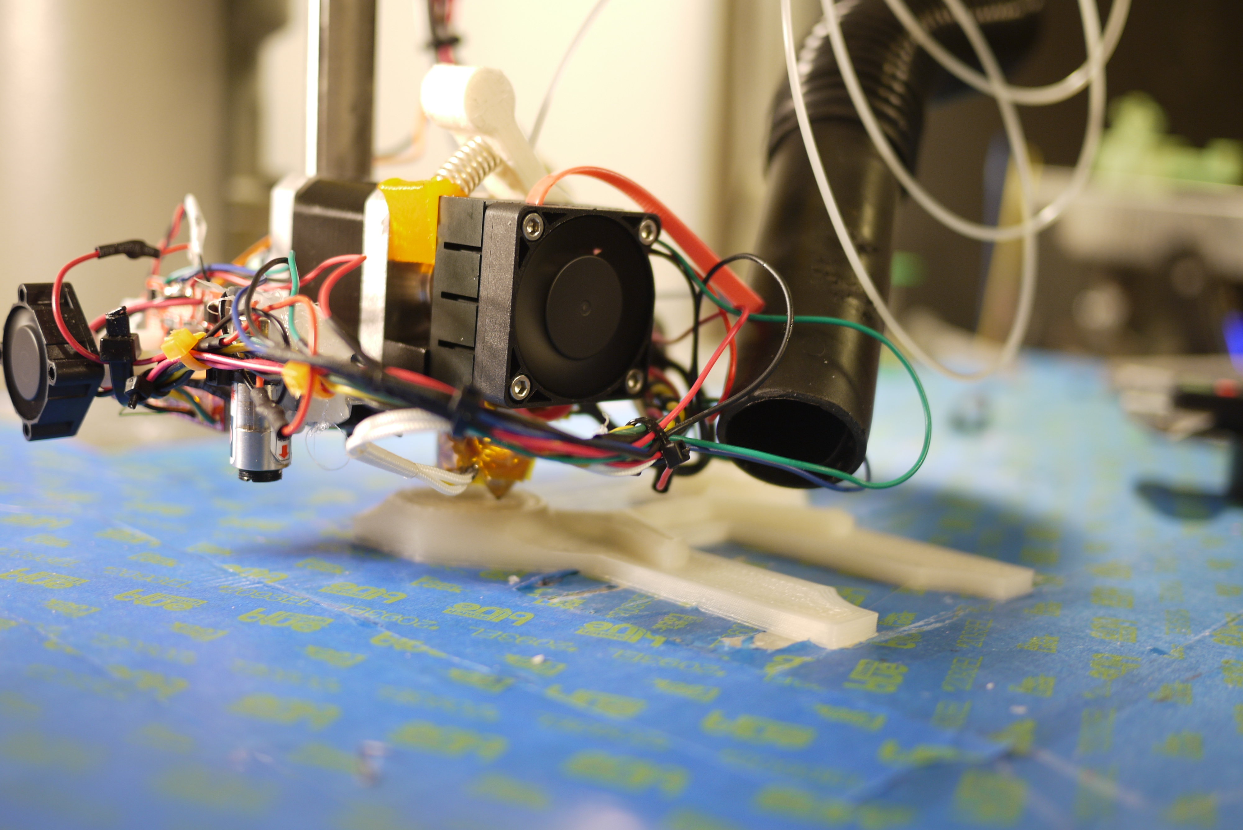
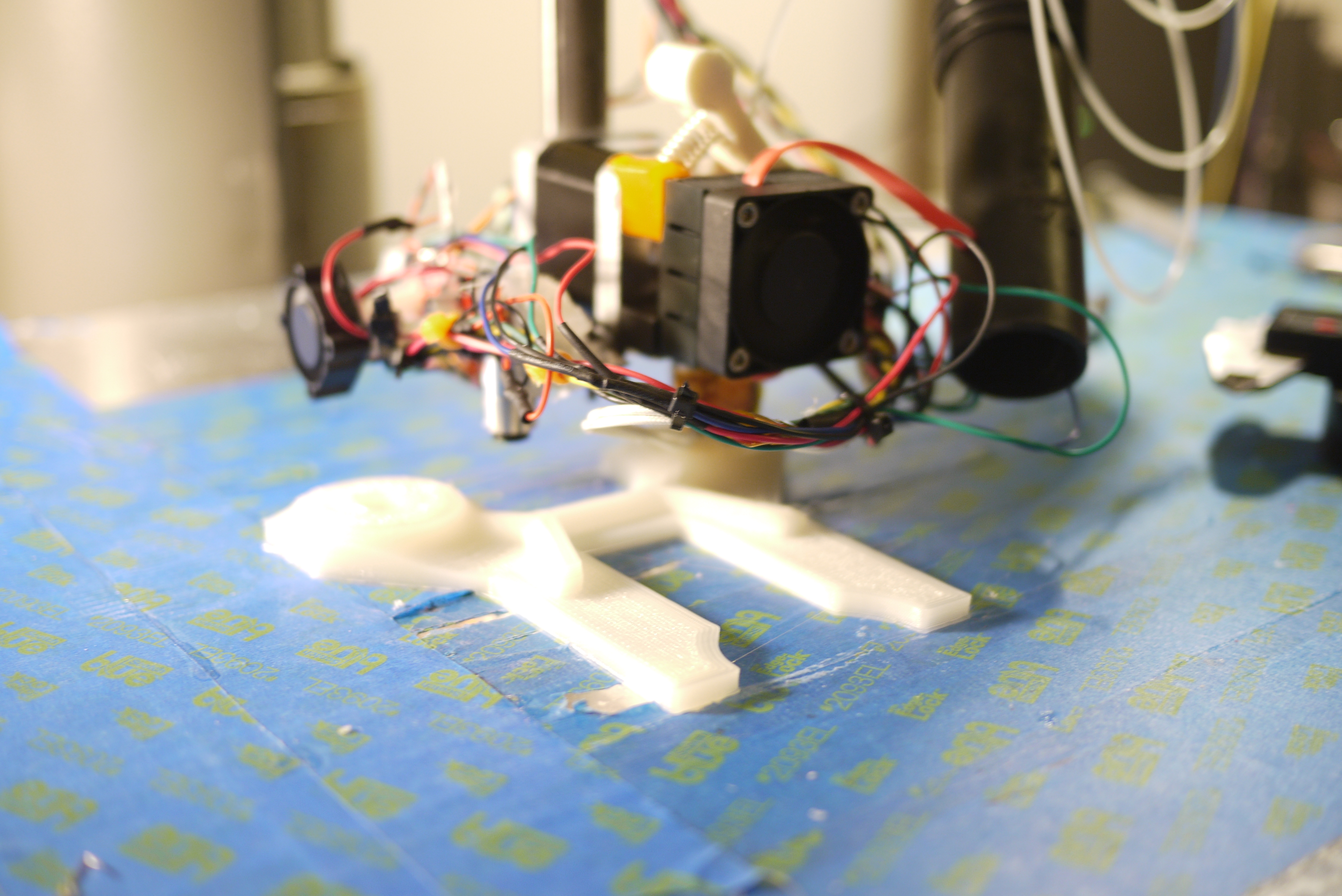
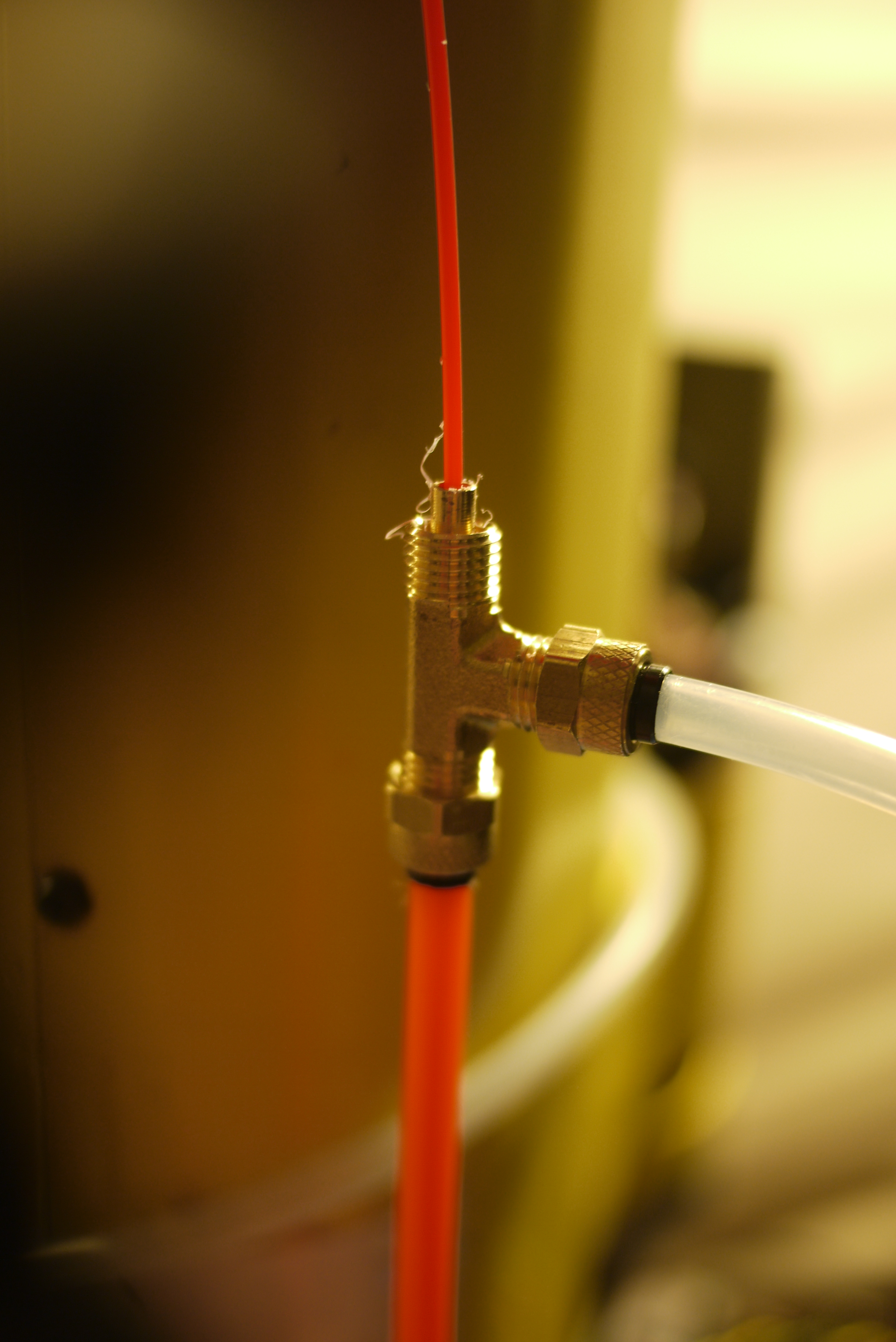
| More
Testing The line was mounted temporairally with hot glue and the cooled air feed was supplied by the above-mentioned 24v compressor pump. As a note, this functioned well, the cooled air resulted in a few hours between extruder issues, instead of hourly. I determined that while the forced air was cooling the line, it wasn't quite cooling it enough |
 |
 |
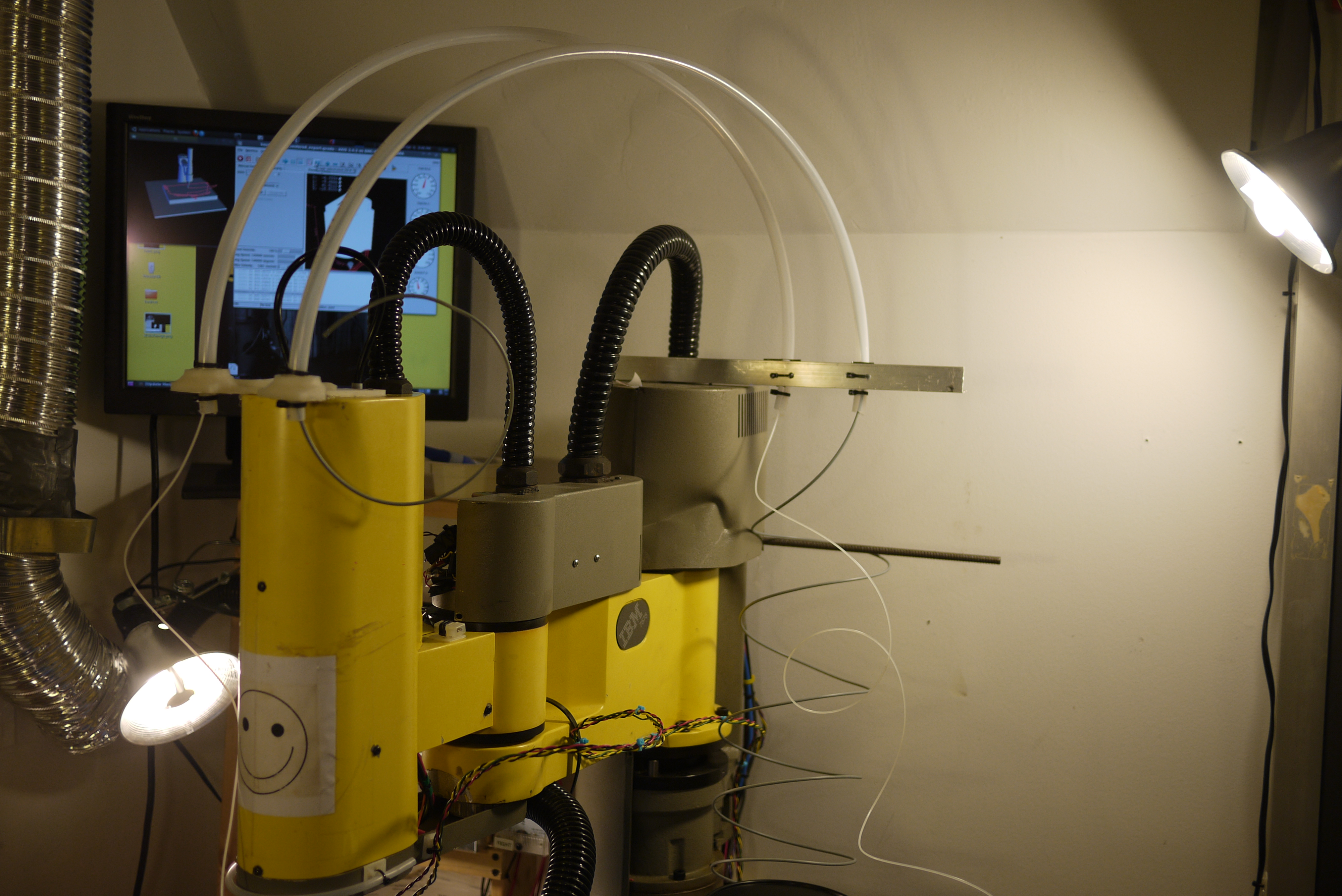
| More
Flow As the relatively small 24v dc pump is limited (and noisy), i chose to switch over to a Harbor Freight airbrush compressor [link]. This is an oil-less compressor, intended for painting.It functions at a relatively high flow rate, while being capable of ~50PSI. This high of a pressure is un-necessary, as the pressure requirements barely exceed 4psi differential. As the compressor input is the 'cool' air intake, the compressor stays outside the thermal chamber. Translucent PEX tubing, kindly donated by a good friend, routes from outside the thermal chamber to the top of the extrusion / ABS feed. |
 |
 |
Tools of the Trade
| List of tools used that made this project happen: | ||
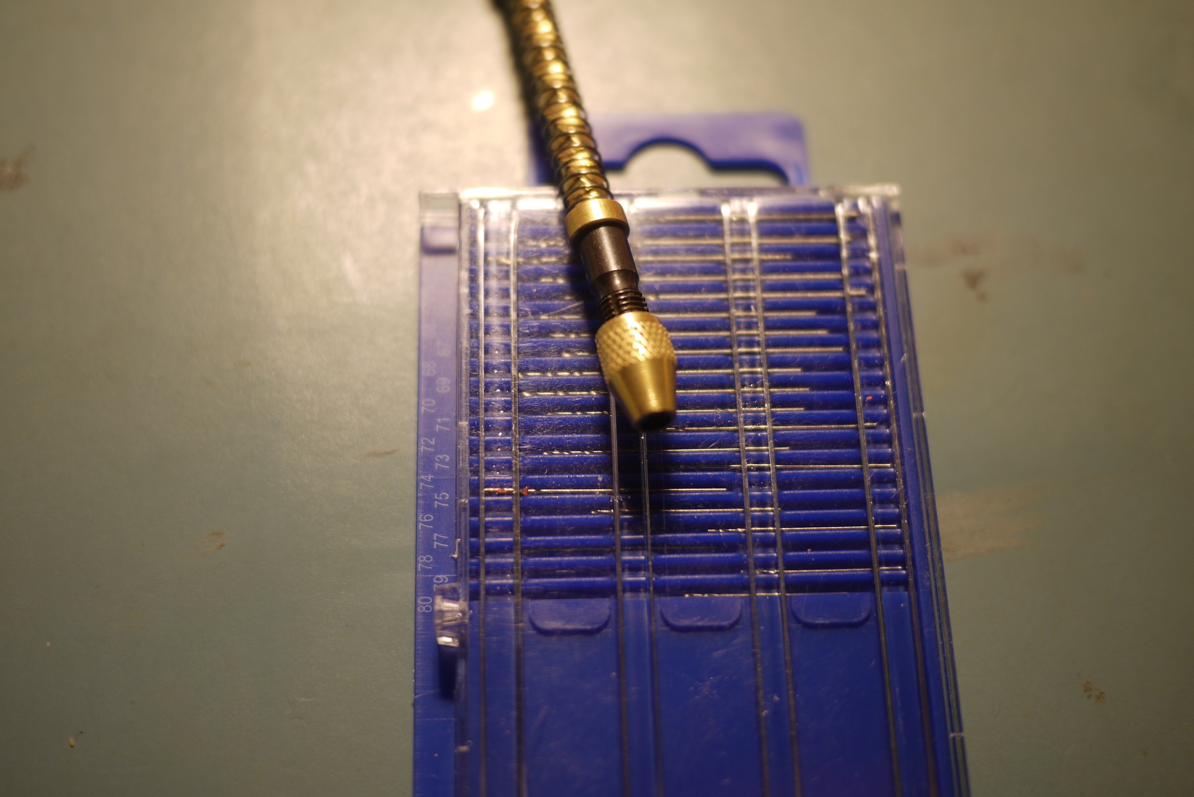
| Itty bitty jewelers drill
& holster I picked this up online. It was listed as a "20 piece Tiny Small Drill Bit" set [link], for less than 8 units. While the spiral drilling device is an odd feature, it does work well at re-drilling / slightly widening a caked filament-laden extruder. The ~20 tiny drill bits are fairly difficult to put in a power tool, so the ultra-small clamp-head of the screwdriver was extra helpful. |
 |
 |
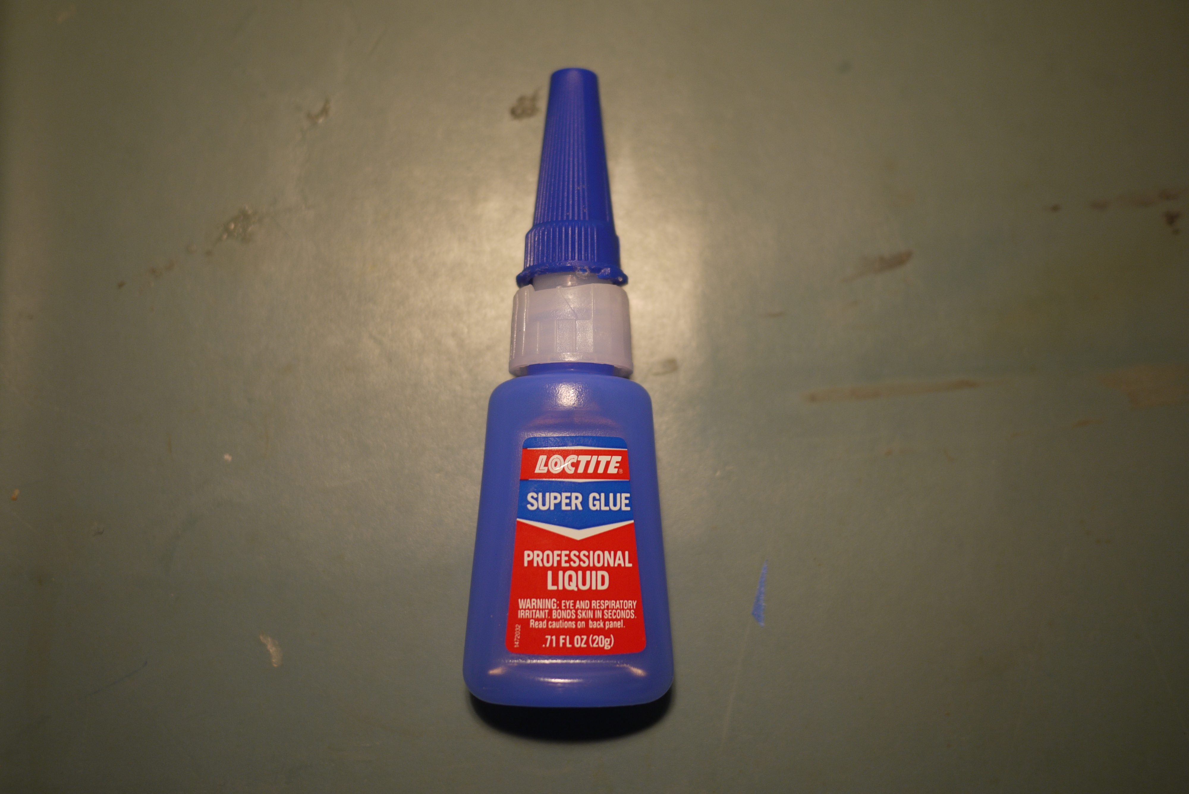
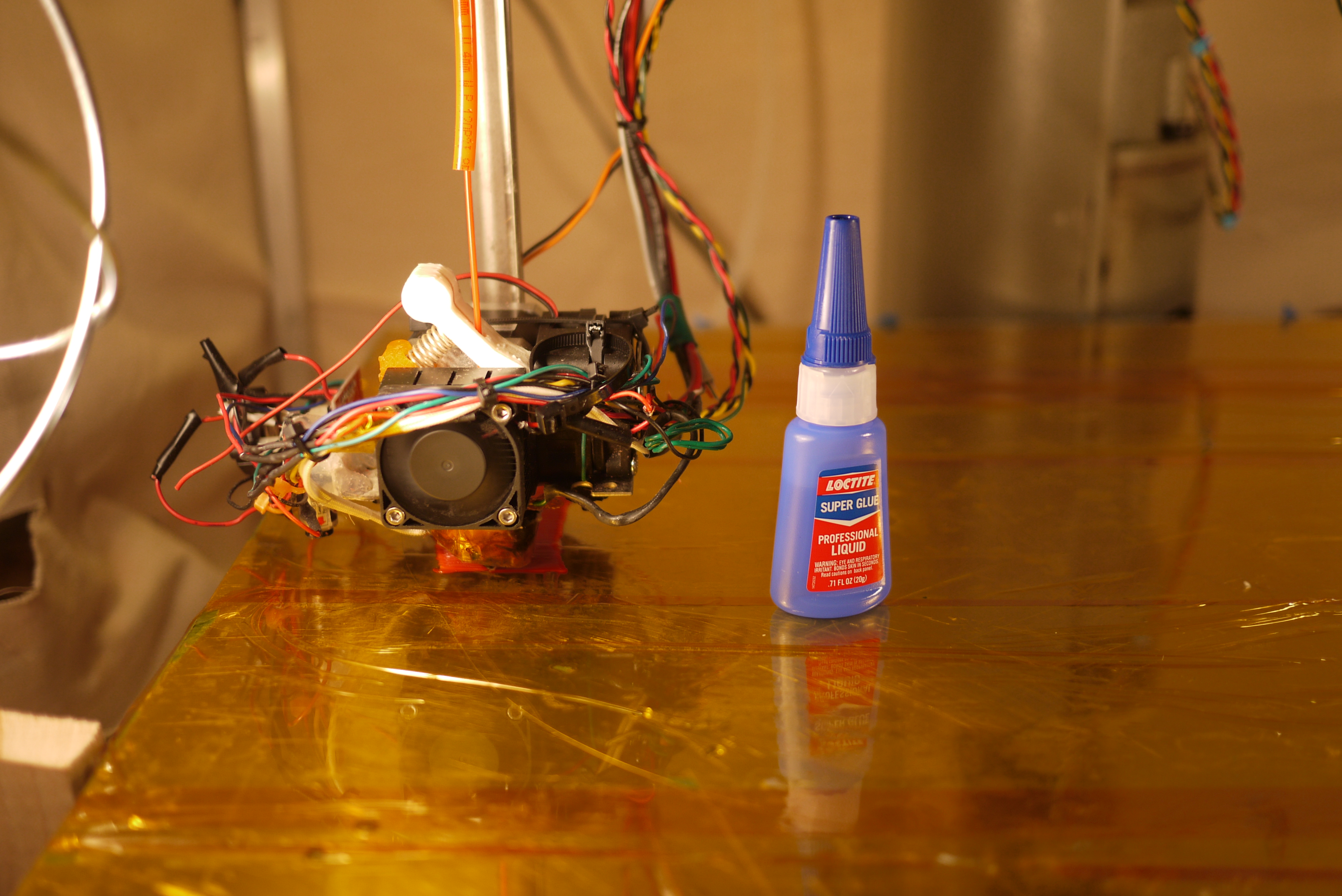
| Loctite
Glue Blue pain The best anti-warp tool out there. Loctite (20g) is pricey, at close to 6$ each, but does a fantastic job bonding the semi-warpy ABS filament to the blue painters tape / kapton bed. I tried a number of cheaper alternatives, and while they work, the loctite is the cheapest & most functional per fluid oz. I had a lot of mixed success with Harbor Freight super glue, it appeared to vary in consistency and cure time with each vial. |
 |
 |
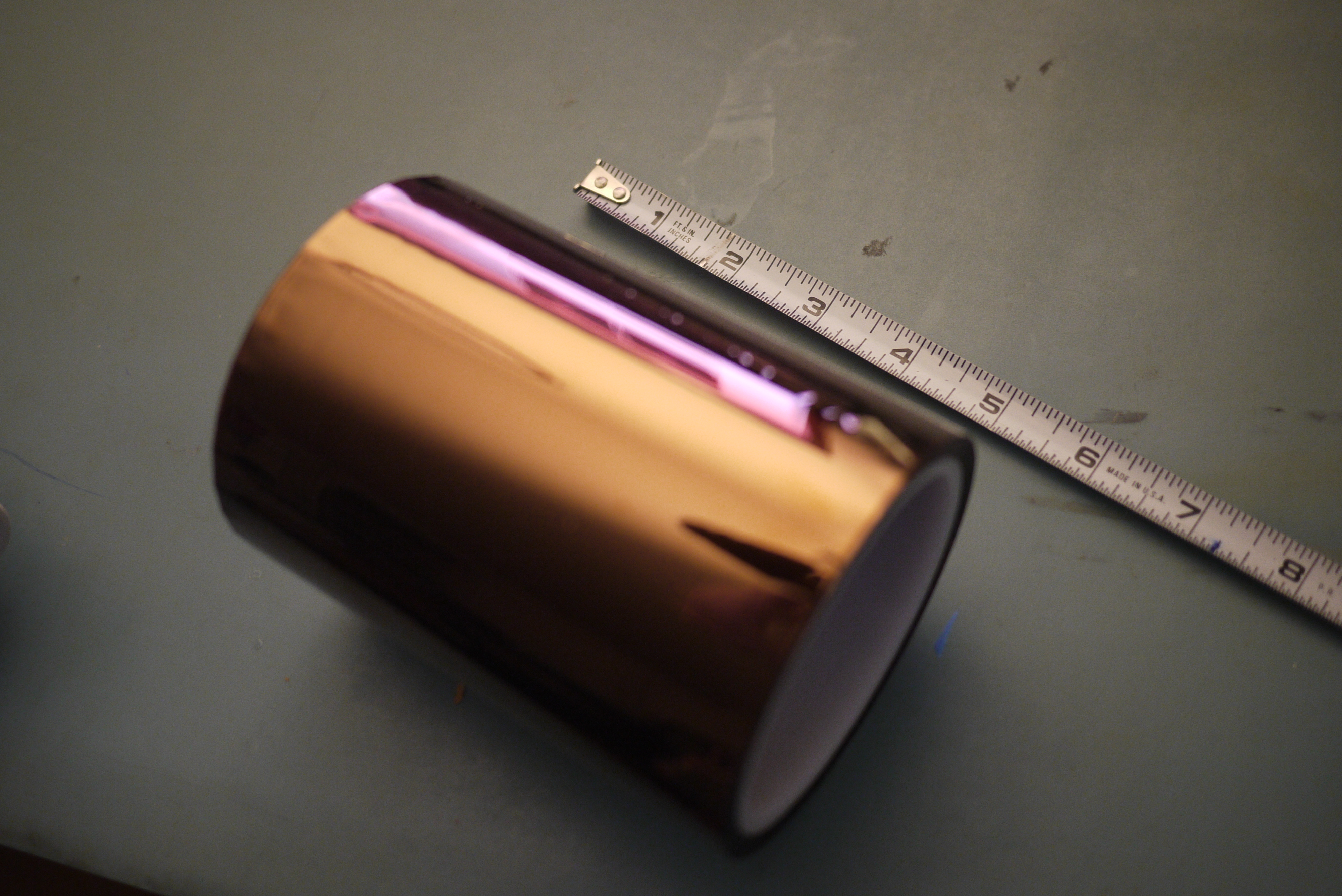
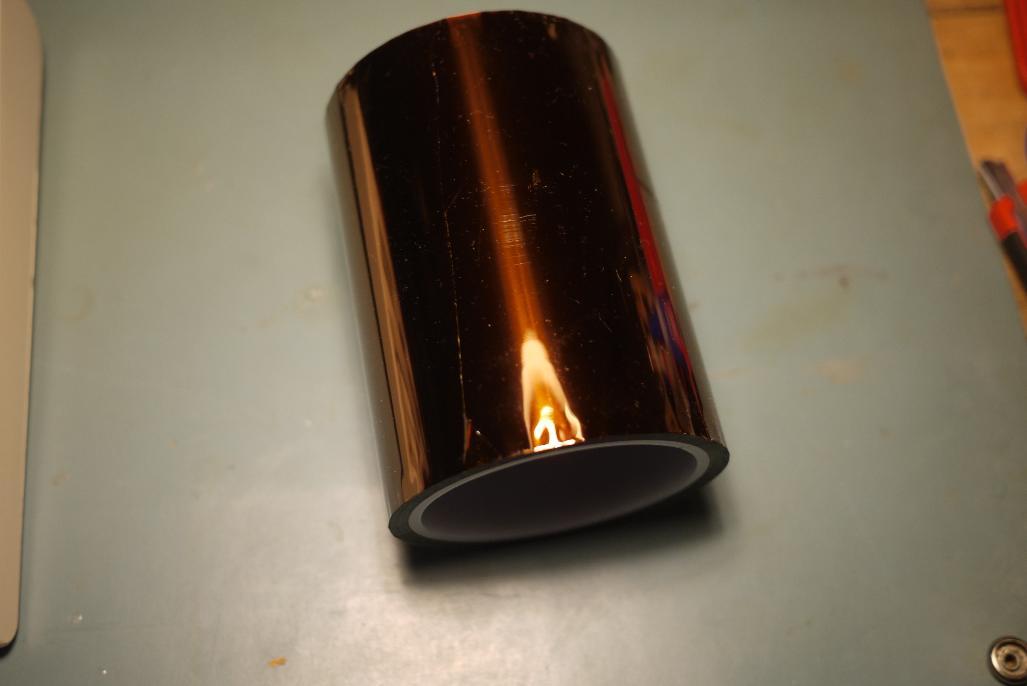
| MEGA KAPTON tape Kapton [link] is a tape rated for high temperatures, with a fairly rugged adhesive. Its outer finish is very smooth and the tape itself does not expand/contract much with thermal changes, which is useful in a heated chamber. |
 |
 |
| Insulation
tape I didn't quite know this stuff existed, but it worked fantastically well to fill the gaps in the thermal chamber, and maintain contact on the removable side. The adhesive, surprisingly, held up to the heat fairly well. Tape was purchased from [link]. |
 |
 |
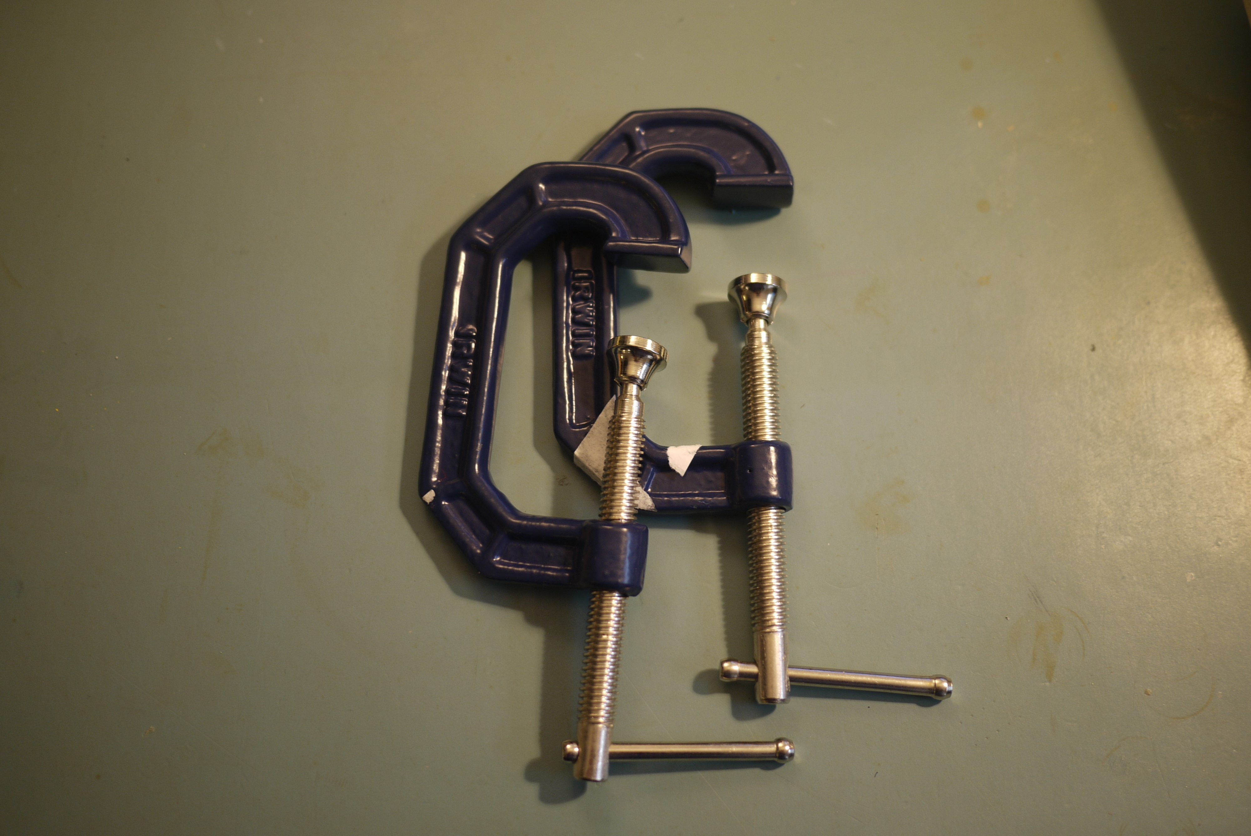
| CLAMPS With a large heated platform, you'd be surprised just how often tiny clamps are useful for holding in place braces, etc. These were purchased at a local hardware store for $1.25 ea. While fairly small they work great at clamping things to the build platform while keeping a low profile. |
 |
 |
Printer Output
| New nicer Prints | ||
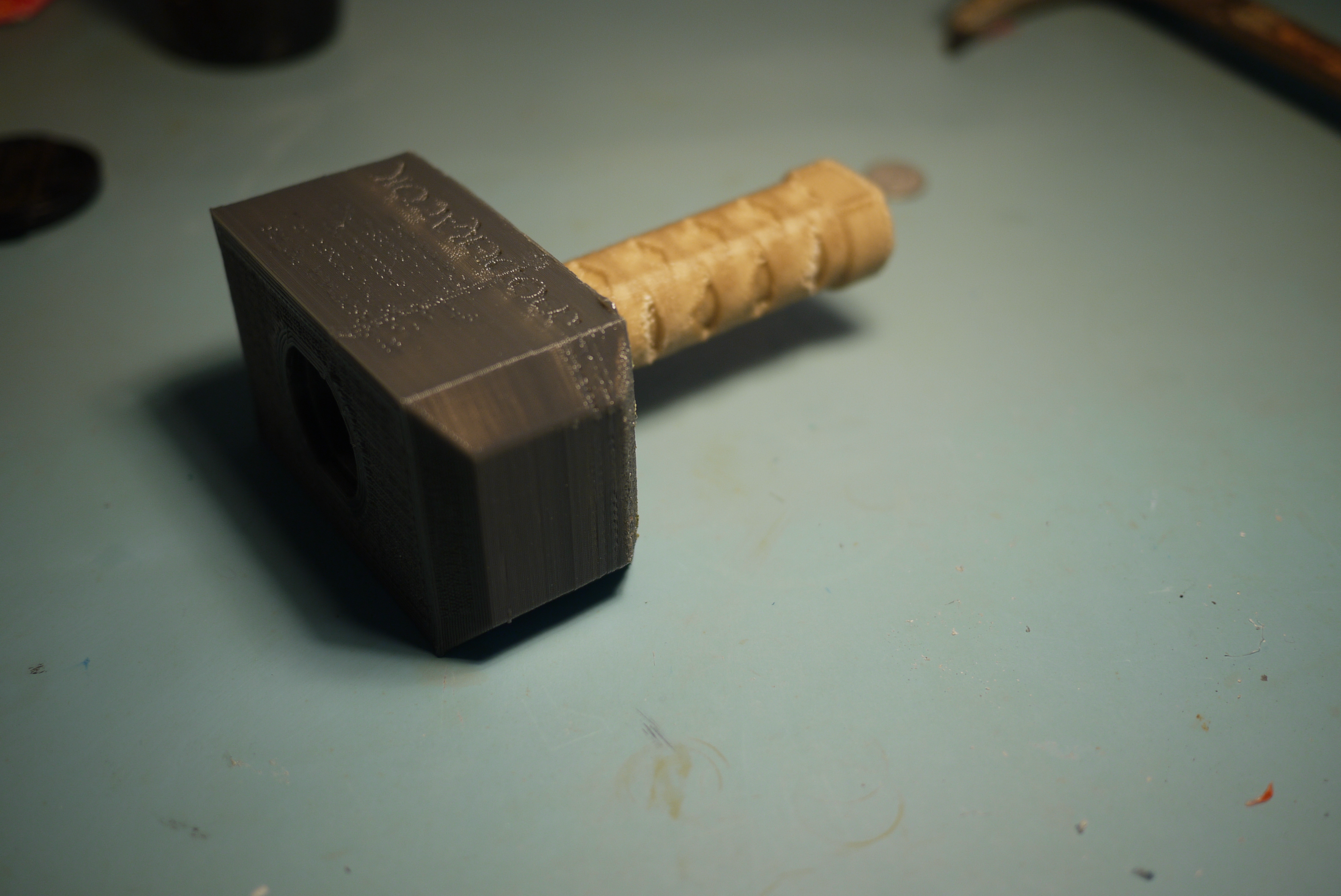
| Thors Hammer This was a recent print, using 1.75mm Grey and 1.75mm brown PLA.The model [thingiverse] consists of 2 parts, which fit, ever-so-snug-ly together, printed as a gift for a good friend's son. As this was a hammer, I printed at ~90% fill ratio. This took a while to complete (8 hours for the hammer, 2.5 for the handle). It weighed roughly 1.5lbs, which is a lot for the size |
 |
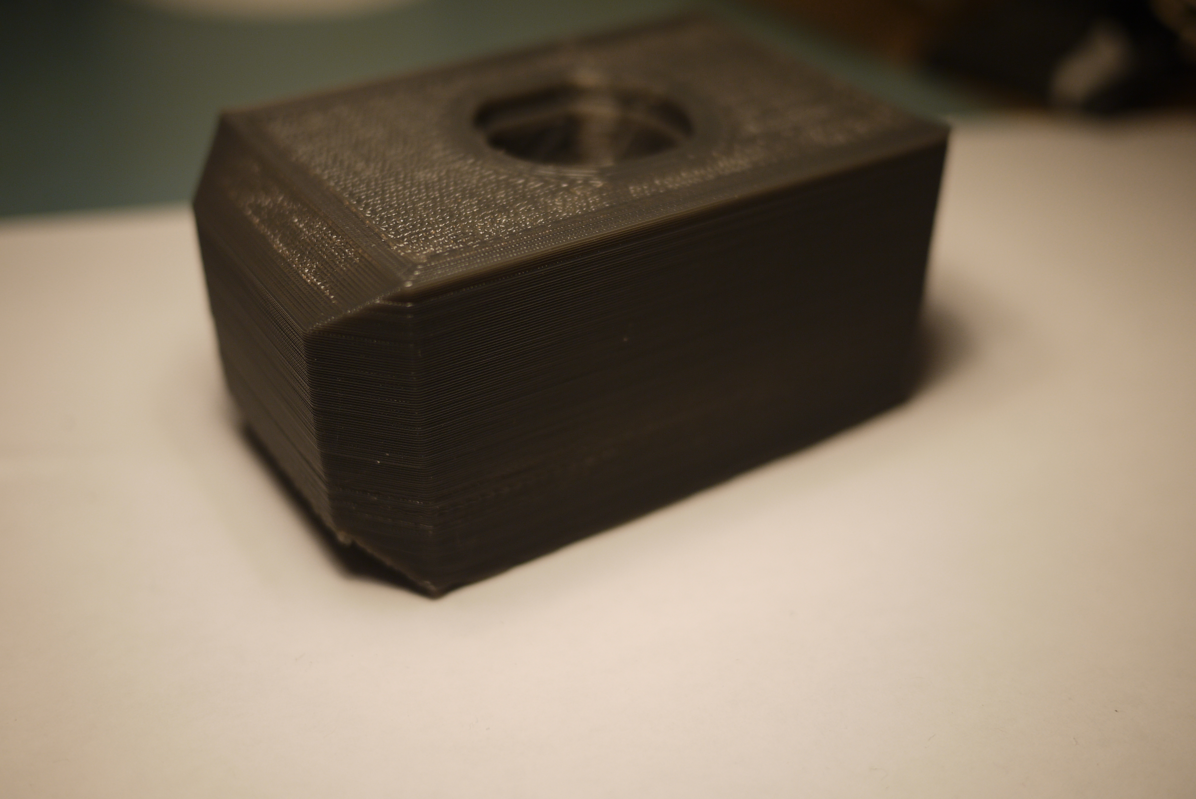 |
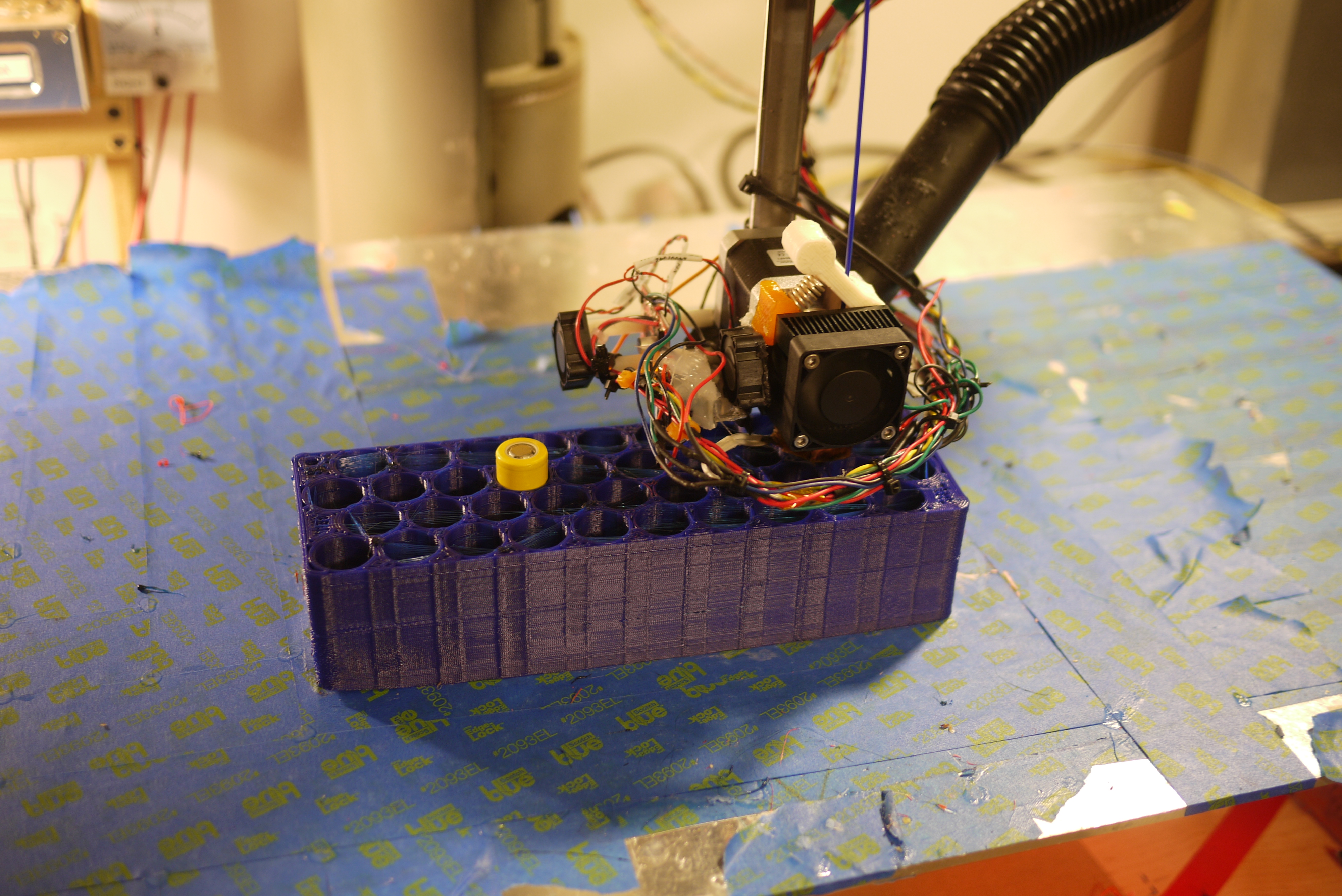
| A
Battery Boxen This part was printed for friend as a battery holster for a new scooter. Note the cell used in the photo is a standard sized laptop cell (18650) from A123 Systems 1.1-1.2 ah. This battery module is setup for 10S 4P cell arrangement. The plastic housing provides nice cell-to-cell isolation thermally, and a more legitimate look than a soda-bottle shrunk module assembly. Note this was printed using 1.75mm blue PLA. Just a note, the Yellow cell did not remain in the part while printing. |
 |
 |
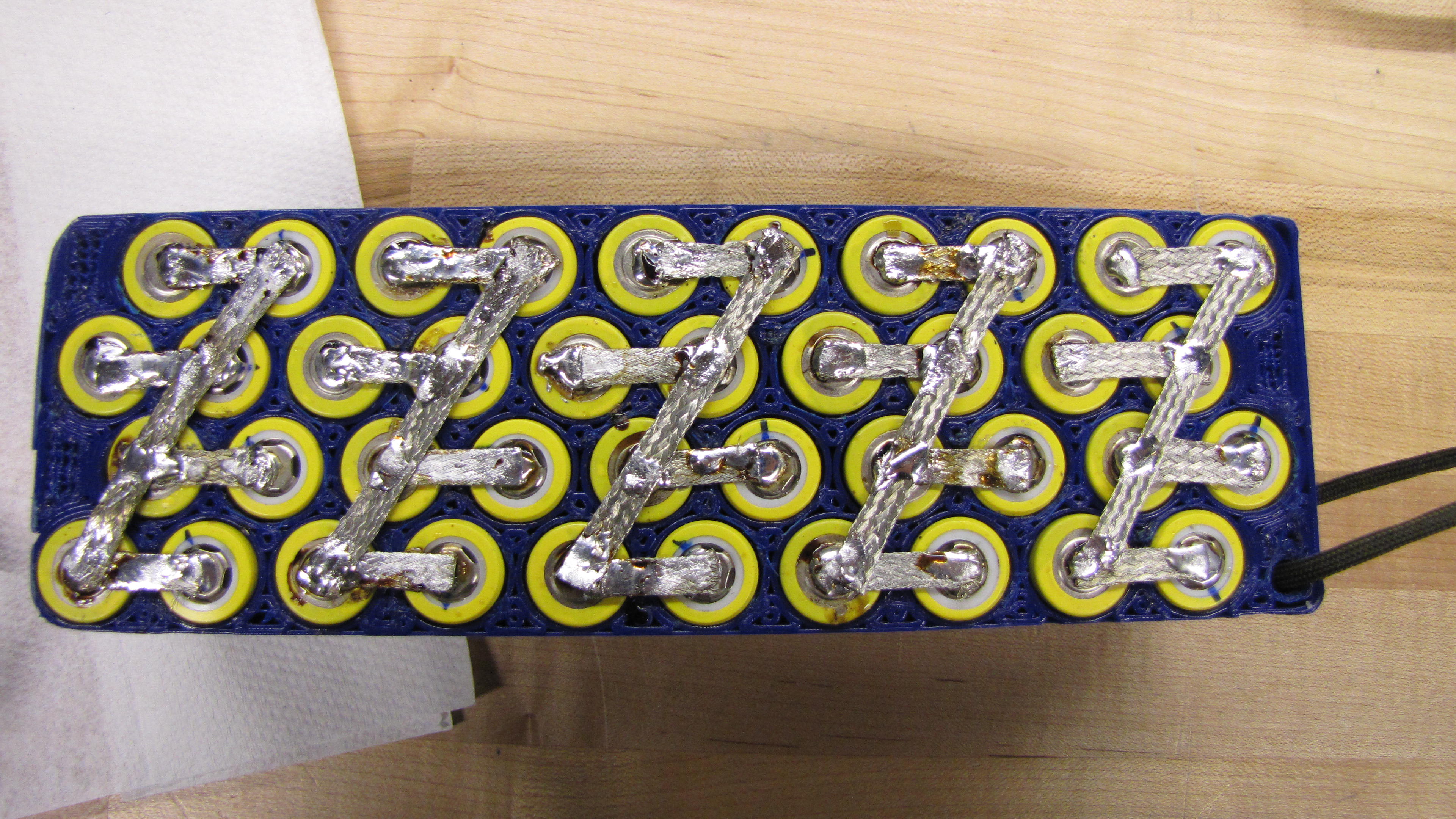
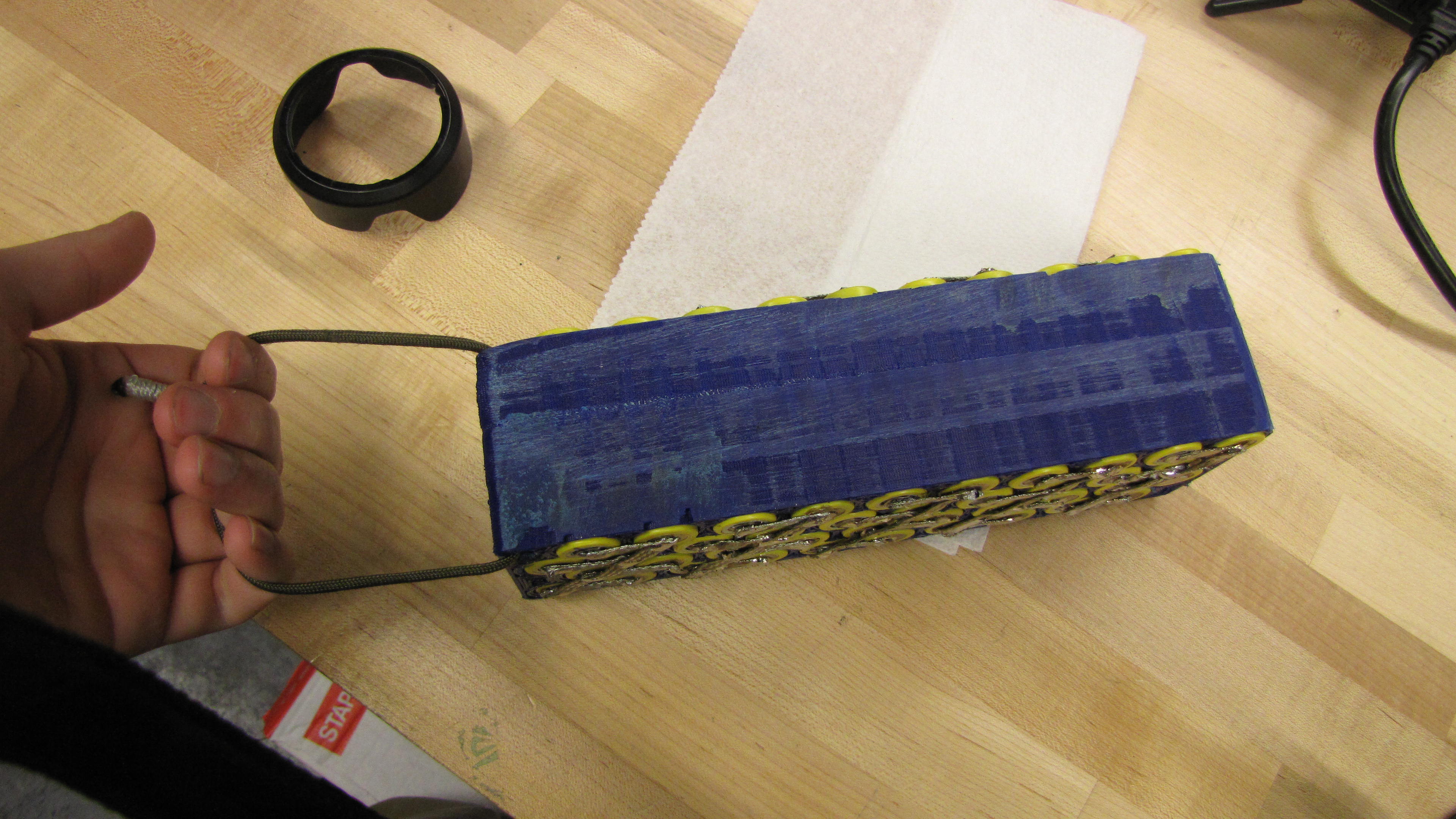
| The
Battery Box Continued This is the module, filled with A123 18650 cells, solder-braided together with very-fluxy solder. Note the sanded portions were to allow for more spacing, as, the container the battery was intended for was slightly smaller than first measured. Note this was completed as a proof of concept for a [comrade's] scooter project |
 |
 |
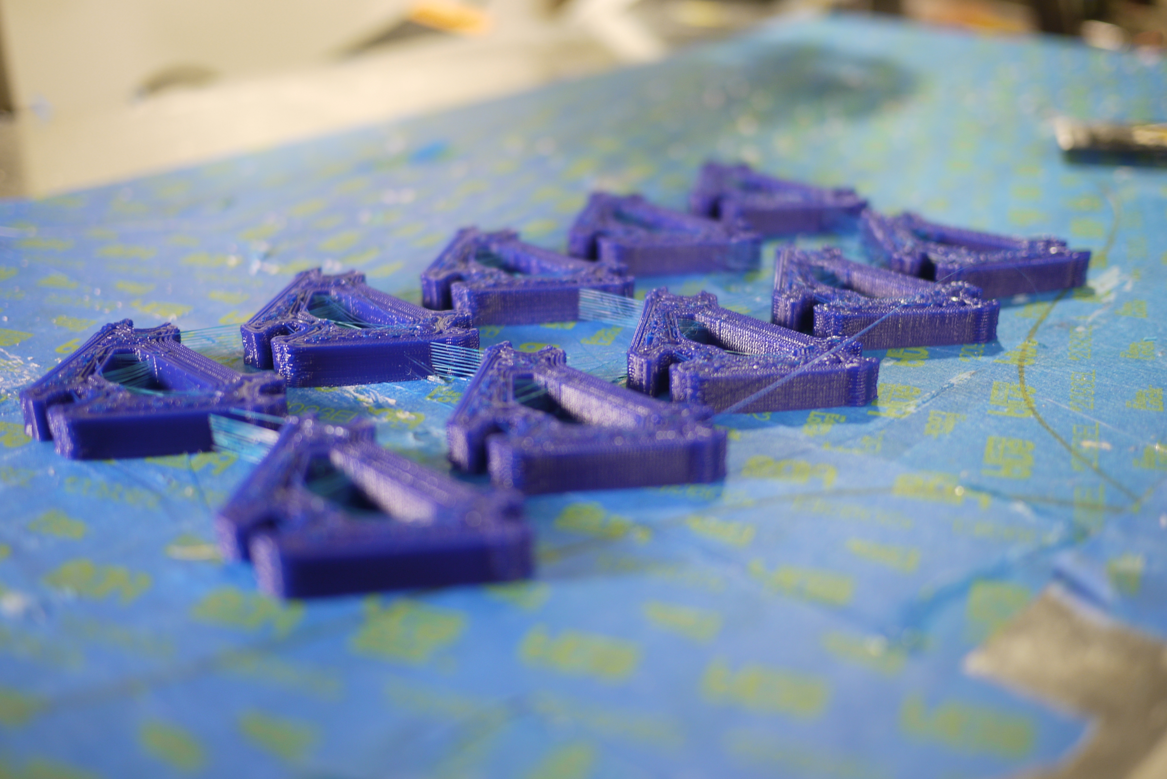
| Parts
For An Imaging Track These are track spacers for a project listed here. This was a quick project, and intended to only really see torsional straining. The spacers are printed from 1.75mm blue PLA plastic |
 |
 |
| Only
the finest in cookie-cutters The cookie cutter was generated for a building wide shindig and was used for making many gingerbread-robot cookies. Note this was printed with natural PLA (1.75mm), and a sheet of saran-wrap separated the print from the cookie dough. |
 |
 |
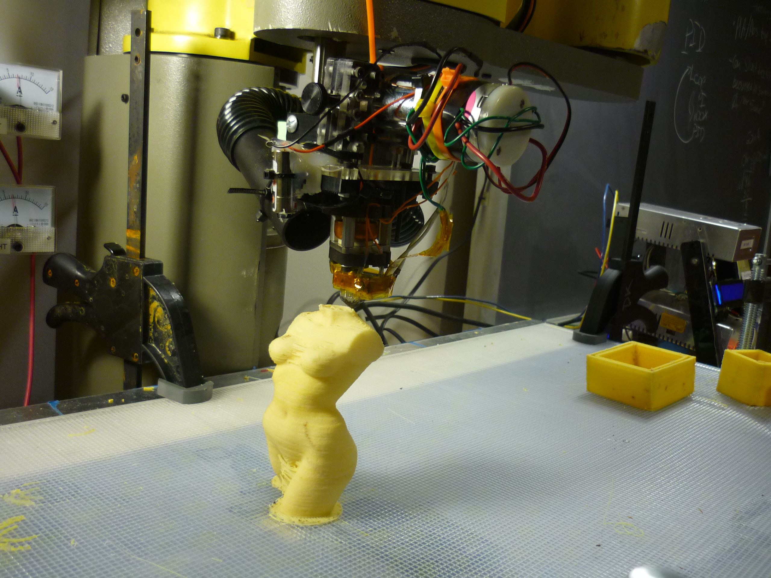
| The
Pink Panther Woman I printed the pink panther woman model, way too many times, but there's a fairly huge difference between v1 and the present hardware+software combo. Note the 'before' image was one of the very first attempts, using 3mm Orange ABS plastic, whereas the 'After' image was using1.75mm red PLA. Note this was a combination of smaller nozzle, better slicing configuration, higher speed printing, better temperature control, and tighter kinematics. Model from thingiverse [link] |
Before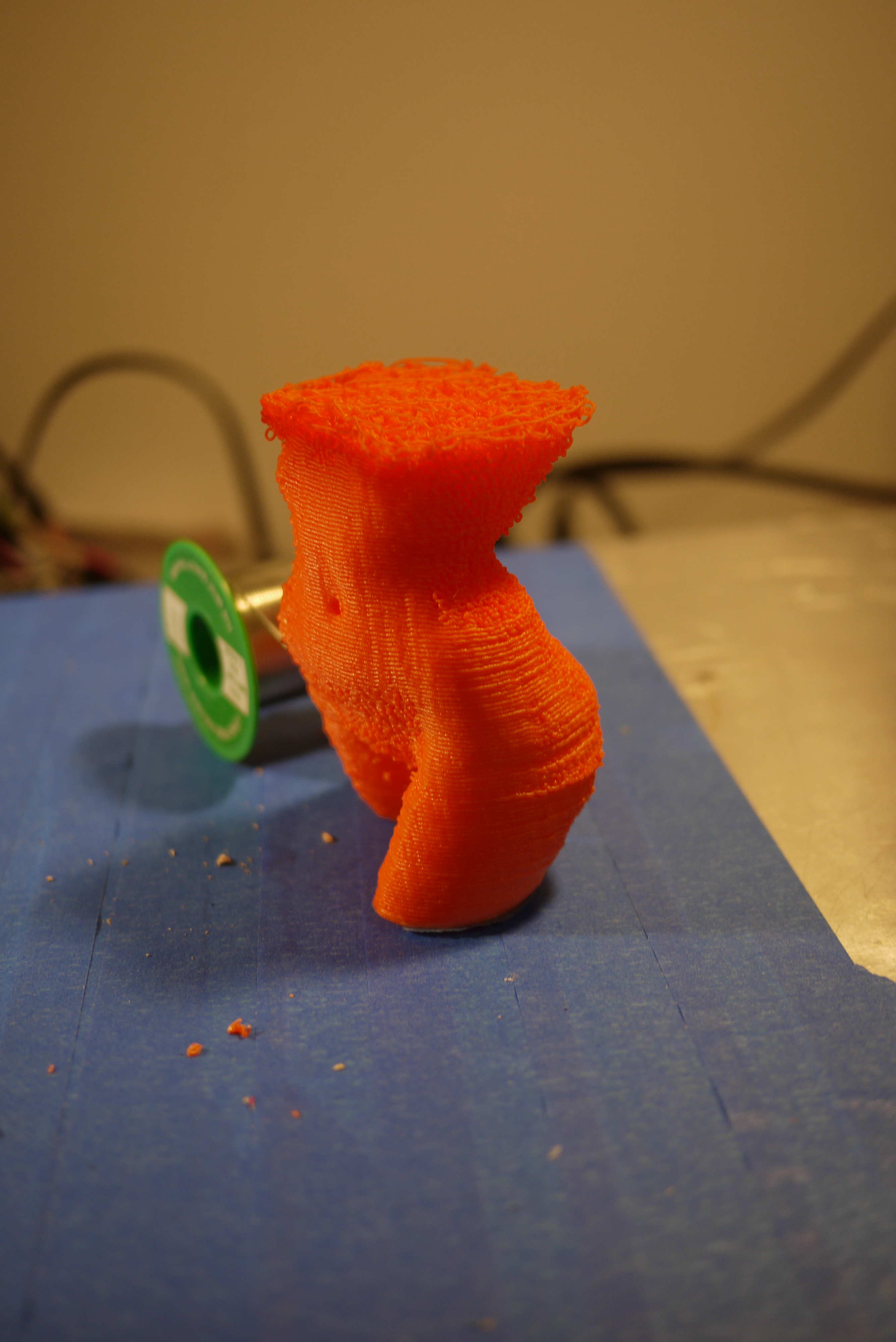 |
After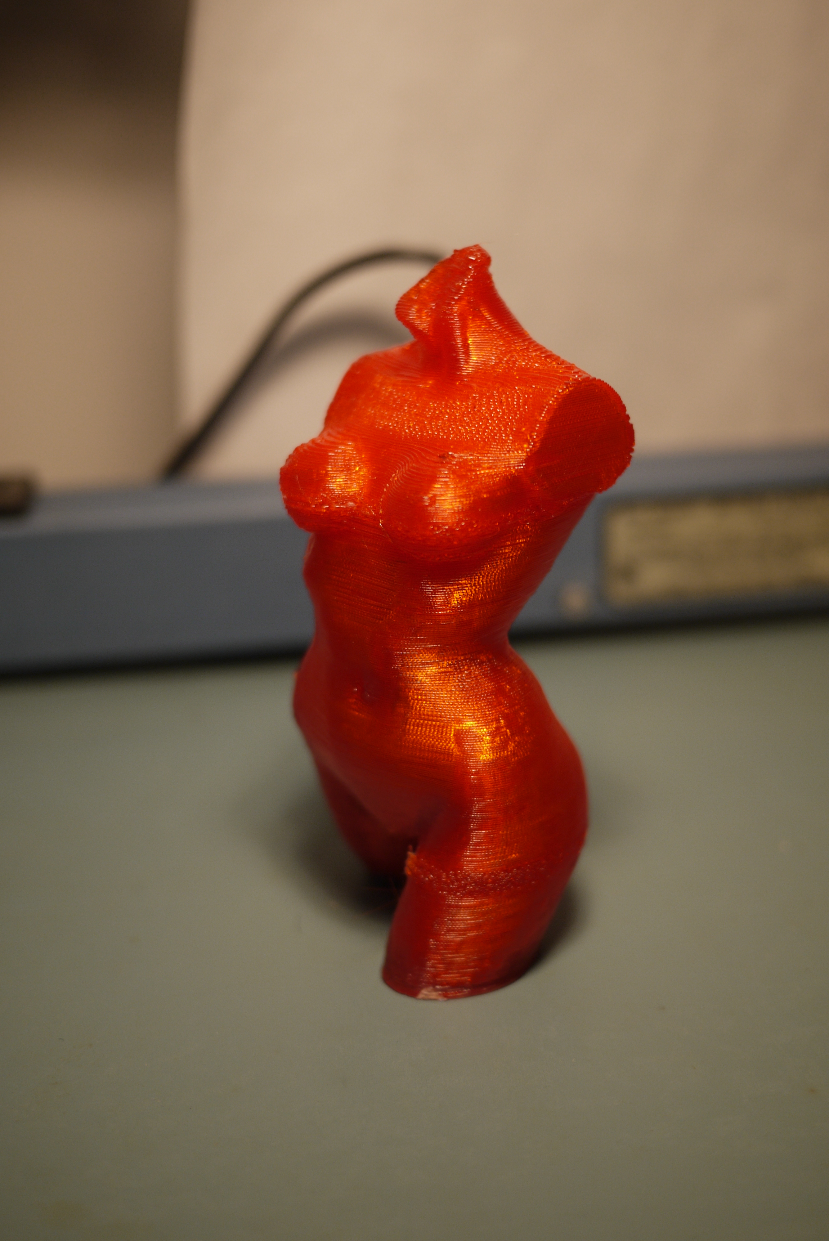 |
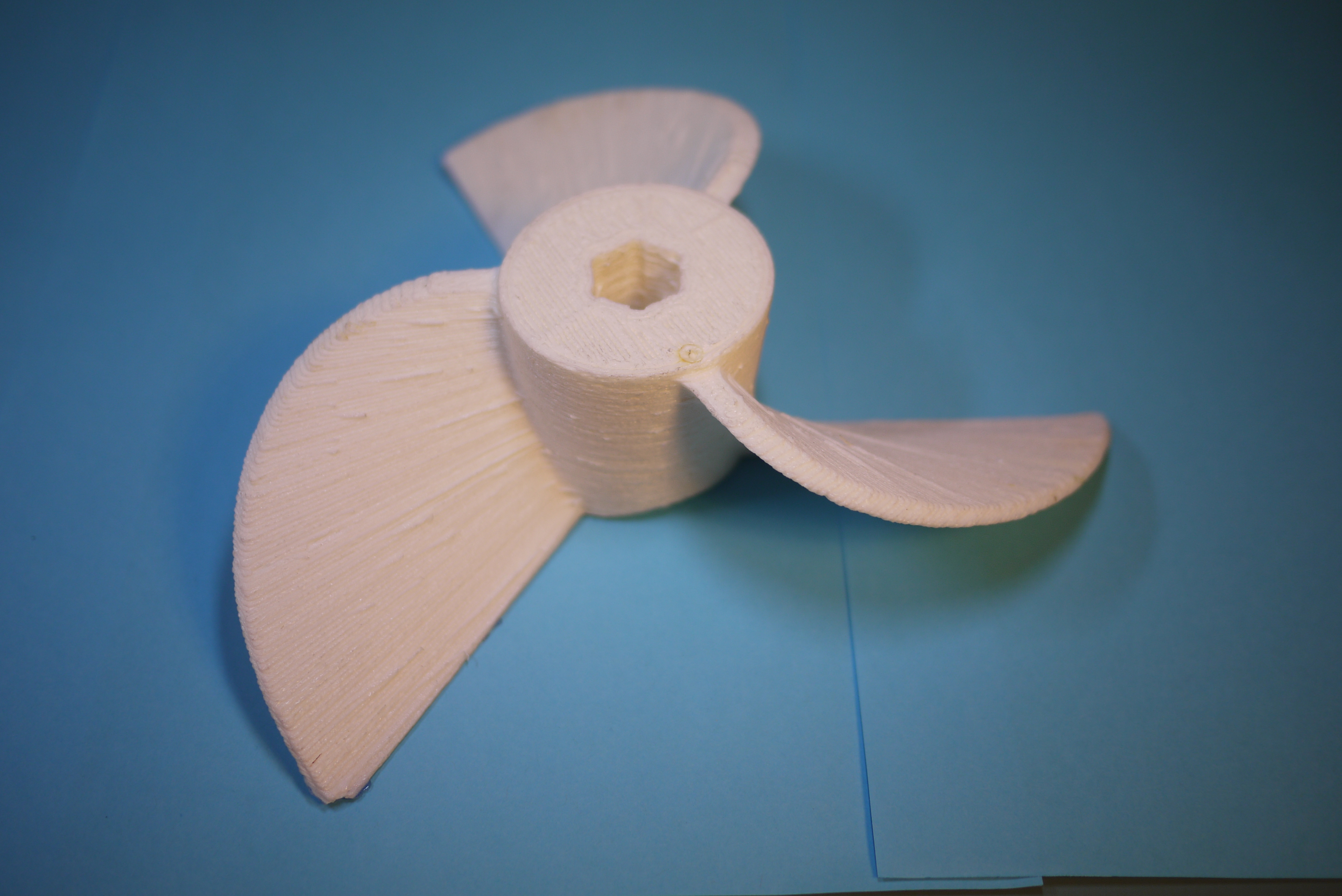
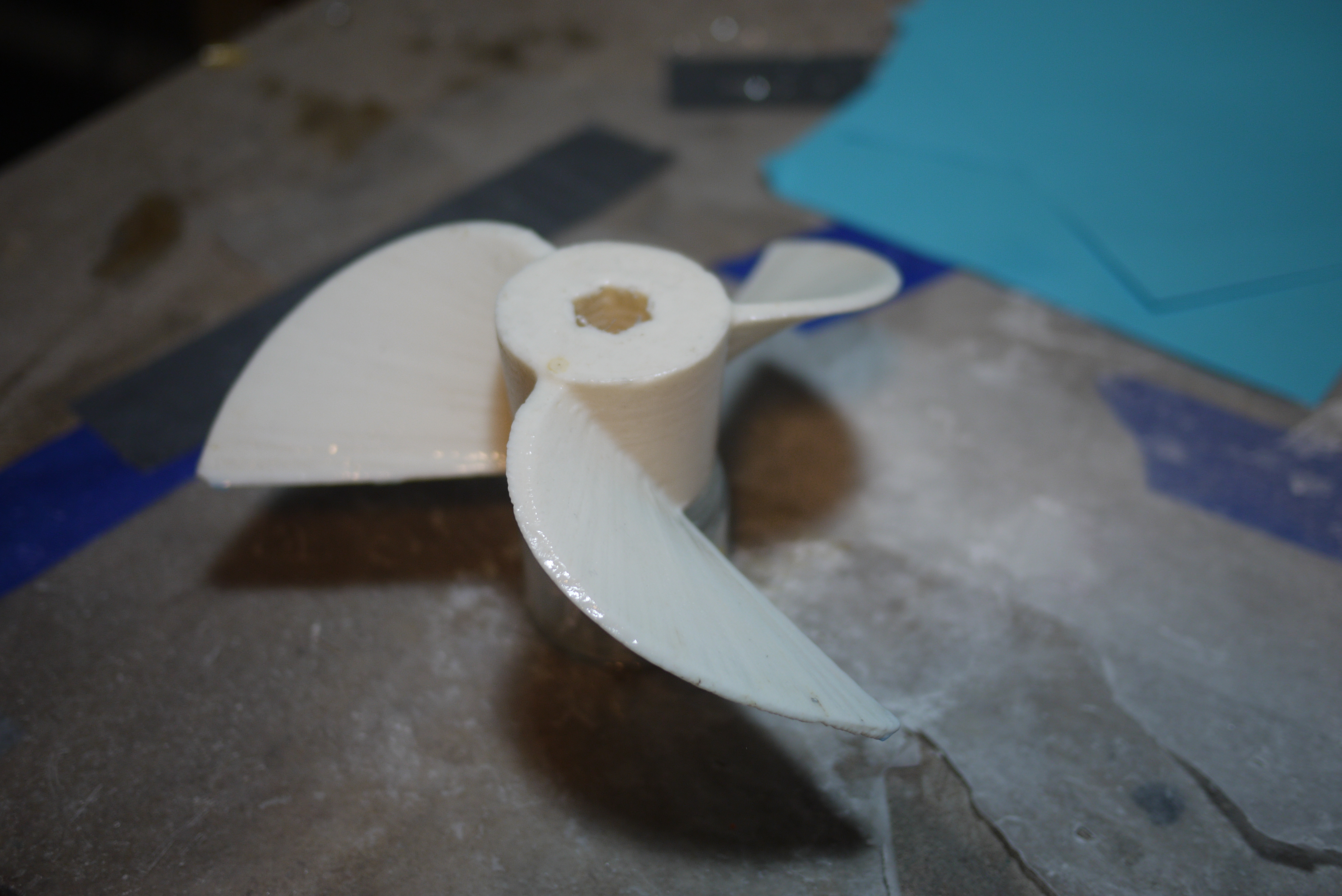
| A
Propeller Forged from Science Itself I was able to take advantage of openprop and design a propeller specifically suited to my thruster, another project. For the first go I printed at a higher speed (and lower resolution). This beast (7.4 inches in diameter) was done in less than 2 hours. |
 |
 |
(There's
other photos of the build in the photo
gallery)
Concluding
Remarks:There was a lot of work that went into these upgrades, some of which were incremental over the course of many weeks. Most of the efforts weren't quite linear and were the result of continuous improvements. The time allocation was fairly large and the project itself became less of a tool and more of a sandbox of ideas designed to coexist. The updates allowed a tighter, smaller layer height (0.4mm, instead of 0.7mm), a tighter spatial tolerance, and a significant reduction in thermal warping, at a faster speed (2180mm/min). Admittedly this machine is targeted towards larger, slightly lower-resolution prints, instead of super-fine detail FORM-1 fancy-prints.The details shown above allowed for the aforesaid advances.
One of the best 'lessons learned' of this project was the importance of a well kept lab notebook [example].
Initial 3D printing started well over six months ago, and a continual series of modifications: mechanical, on the machine, the software governing the machine and the gcode slicer were all happening in parallel. The only way to keep these three balls in the air was to keep a written record of previous functioning states. Development wasn't a daily activity, weeks would elapse where I was preoccupied with other tasks, and when free time finally appeared, reverse engineering what I did two weeks earlier at 3AM before work wouldnt have been as productive. I was able to snag one of these brown top lab notebooks from a lab-cleanout, but you too can be an engineer, thanks to amazon [labnotebook link]. 3D printer plastics quality also varies significantly between vendors. SAINSMART is by far the best brand of abs / PLA ive used during the ~6 months of experimentation. The quality and color is identical, and they are packaged in bags to prevent moisture intrusion. Check them out.
Pictures and video are also worth their weight in words (and megabytes). I was fortunate enough to get access to a very excellent Panasonic camera, which, quite honestly takes better pictures and video than in real life. Snagging photos of developments, and leveraging comrades for feedback was HUGE. The cooled filament system alone came up while talking to a co-worker, and having access to the photos over the web (keeping an active, synchronized directory) allowed those connections to be made, and implemented the same day.
Tenacity and time management were also fairly huge.
3D prints take time, whether on a Makerbot Replicatior 2 or a 'smiles mcgee' industrial robot arm. Finding time to schedule, was huge. If there was an open weekend of tinkering ahead, parts needed to be ordered well in advance, to allow for shipping delays and super weather whatnottery. It also meant 'parallel-izing' tasks, while I wasn't comfortable leaving the machine running alone for hours, I was able to get other things done in parallel, namely jogging, CAD'ing battlebots, or miscellaneous apartment chores. Skeinforge itself is a rather large time-sink, for LARGE prints, slicing time can be in excess of 2 hours, even on a fast machine.
Finally, errors and quirks always show up, it can be anything from a MAGICAL BOWTIE KNOT IN THE FILAMENT YOU ORDERED FROM A VENDOR nearly tearing everything apart or just a power blip. Tenacity is huge. Keeping at outstanding tasks and removing issues, almost maniacally, makes things happen.
Special thanks to those who gave feedback, advise, and put up with my constant reply to most queries 'we should print one' .
If you have questions or comments, ask below or send over an email.
| Comments: |
|
HTML Comment Box
is loading comments...
|
(be
careful, im not responsible for your increased power usage in the
name of science)
Dane.Kouttron
Rensselaer Polytechnic Institute
Electrical & Electrical Power
631.978.1650
