
Dane Kouttron
Project Documentation: 06/2016 Reformatted: 01/2024
1KW DC Outboard Thruster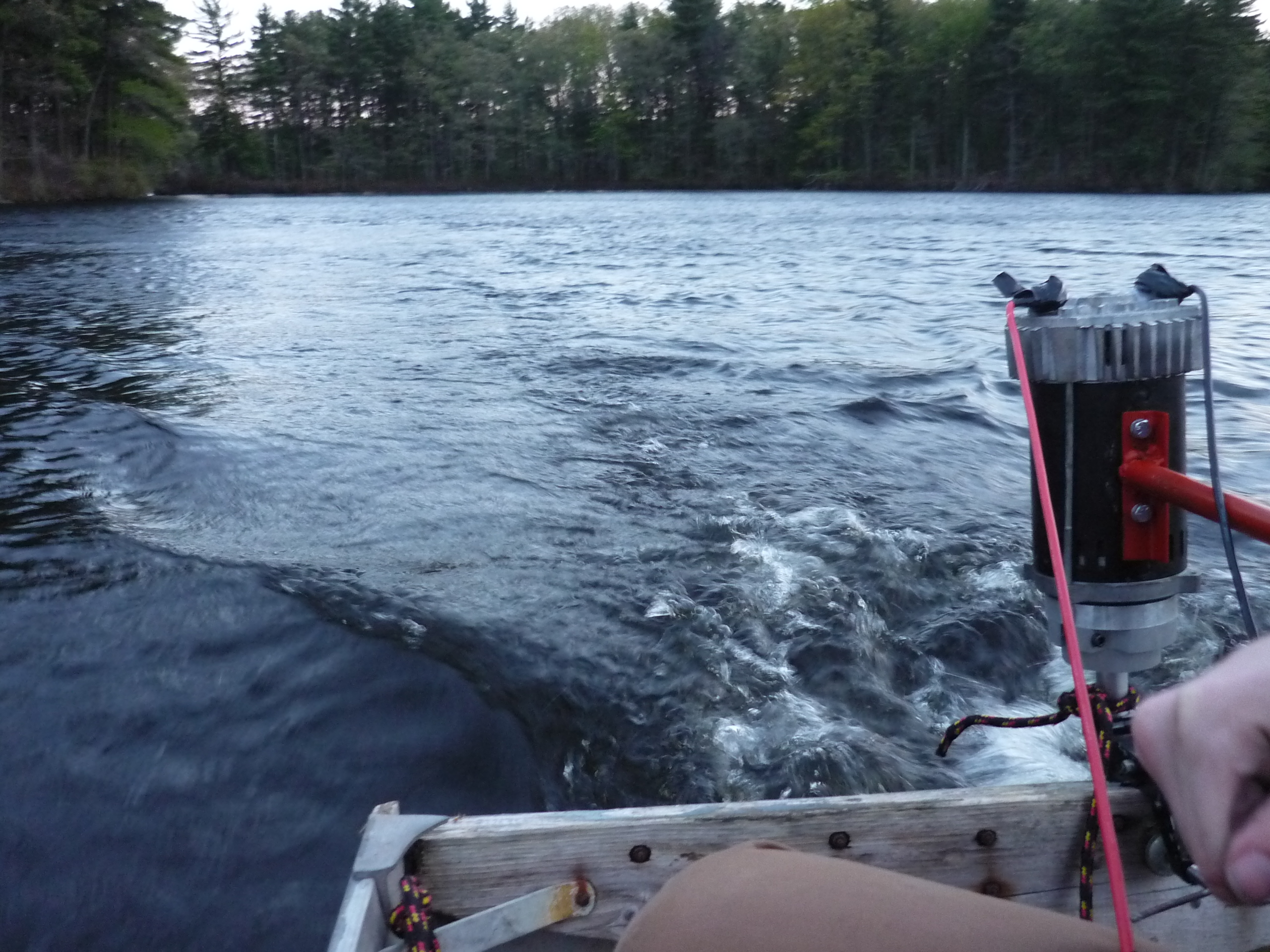
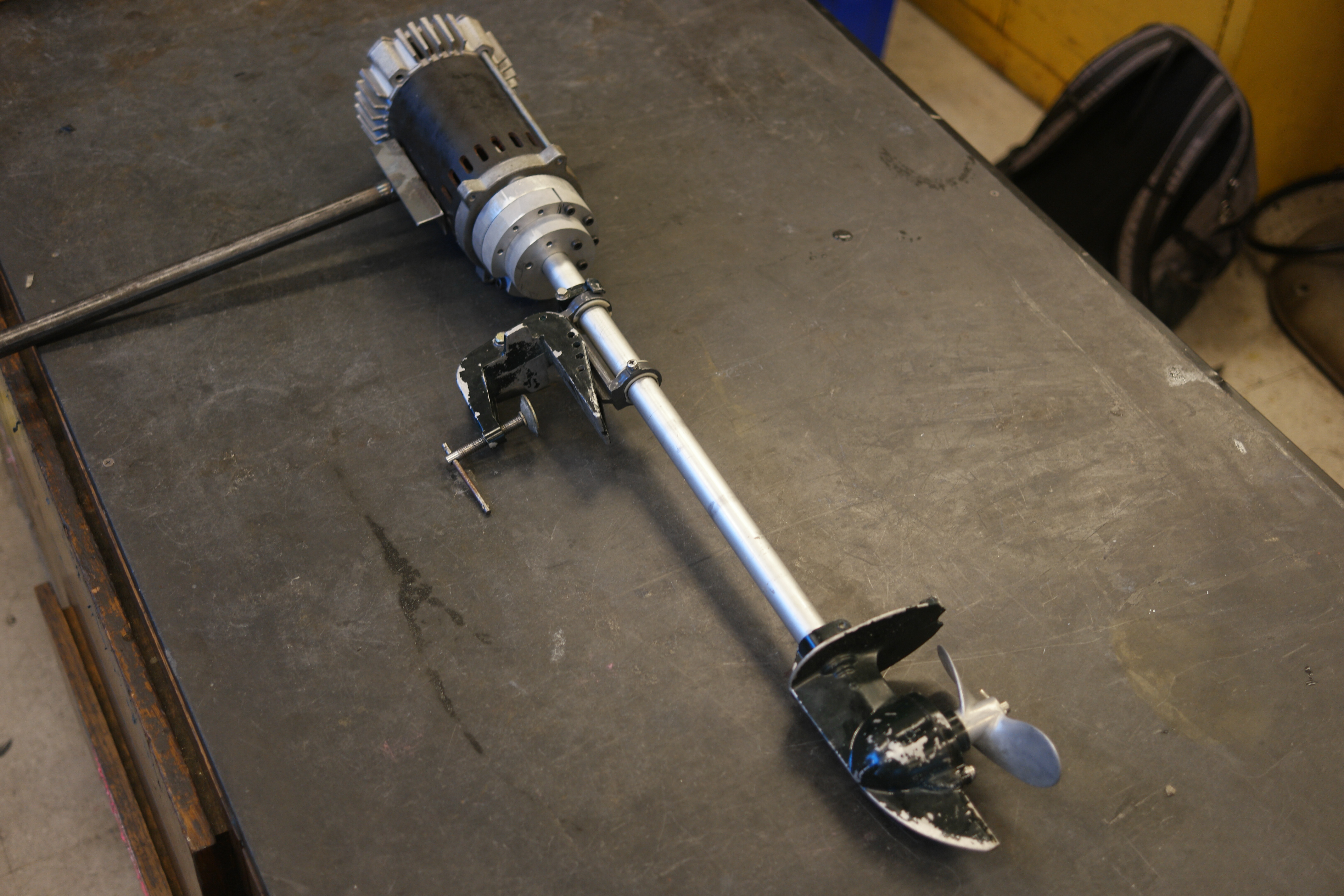
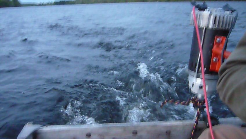
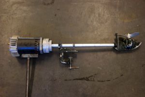
Electric trolling motors are generally quiet, 300w self contained a fully submerged DC motor and propeller assemblies. This design has some disadvantages, namely water ingress into the motor through shaft seals and serviceability limitations of sealed systems. For this project a larger DC pump motor is used to replace a gasoline driven outboard, the motor is kept above-water and uses the gasoline outboards shaft and transom mount. Total power hovers between 1000 and 1100 watts when attached to a small watercraft. |
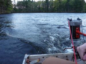
The First Test of The 1KW DC ThrusterSurprisingly peppy on a small rowboat craft. This was built between 8pm and 2am on a Saturday and tested rightfully that Sunday by myself and Birkel. Note, the noise was mostly due to he camera being coupled directly to the aluminum boat, the pump motor itself is a fairly loud device due to its internal cooling impeller. Why not just run a gasoline outboard?
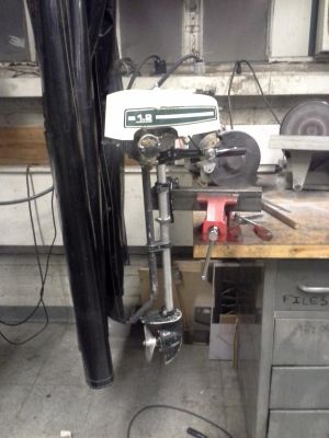
Gasoline outboards in the 1-3 hp range are actually fairly easy to come by, there are however some disadvantages: Removing the EngineThe engine from this outboard is actually a 1.2hp Sears Gamefisher outboard, surprisingly parts for this thing still exist [link]. Fortunately, the mighty Fred had a use for the engine half, for some flying contraption, so I felt less bad about taking this thing apart. The whole outboard is fairly tiny, engine included. I havent benchmarked or dynomometerd the engine itself, but 2-stroke engines are incredibly power dense. Note that the transom mount and associated hardware are included in this photo, its a fairly nifty. Here's a video for how loud this thing can get with an engine [link] 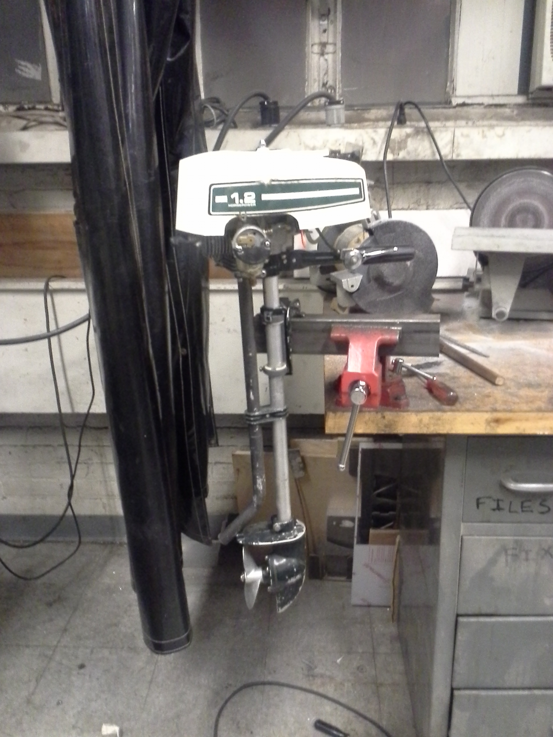
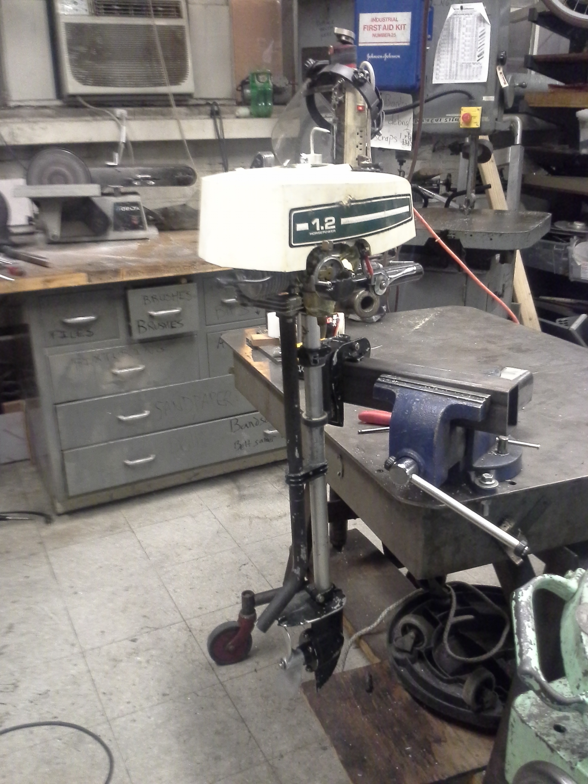
Disassembly time! The engine comes apart fairly easily, the top cover disappears and the whole engine can be removed with three flathead screws that mate the 'outboard' part and the engine itself. 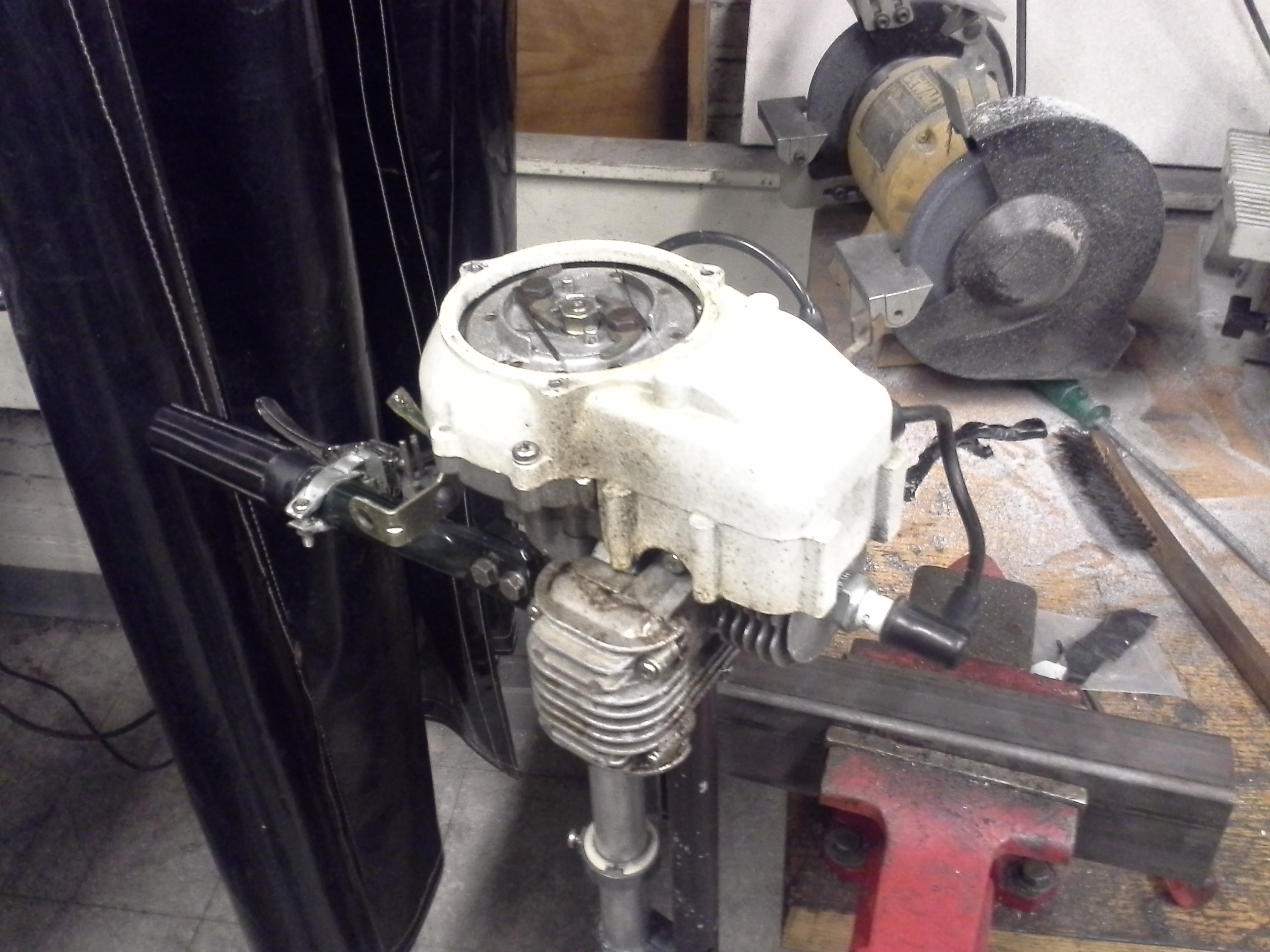
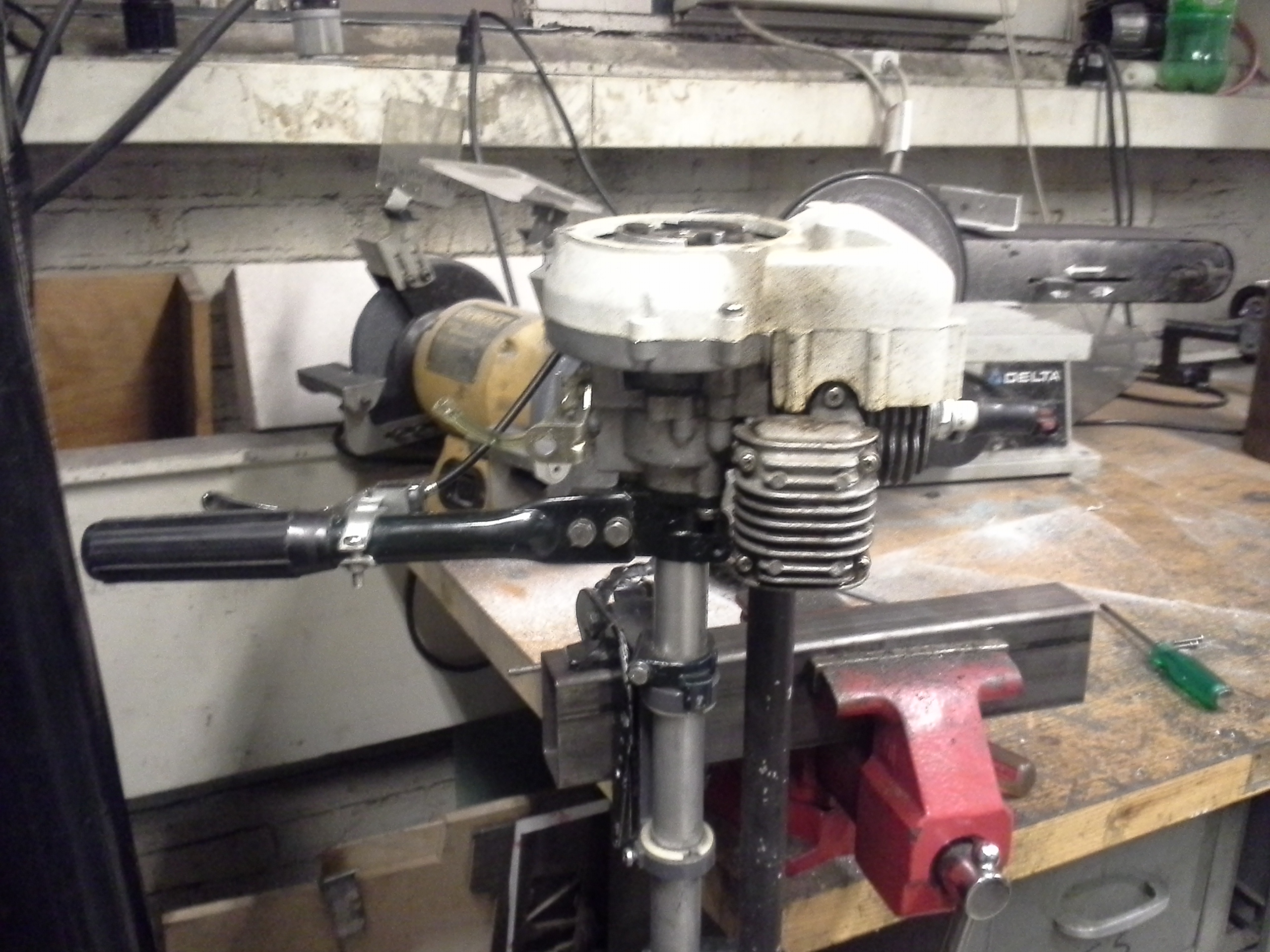
Shown is the bottom of the engine with the three screw mount around the outboard shaft assembly. The outboard shaft itself mates to the engine with this odd shaft + pin loose coupling. I think this may help remove shock load from the engine but also allows for easier assembly in a factory environment. 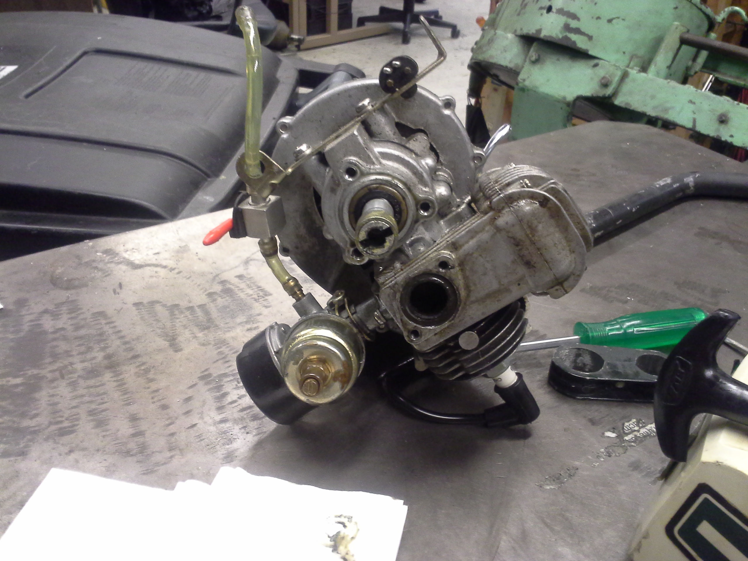

With the outboard shaft an prop removed we begin electrification. Shown is the opposing mate to the outboard, inside the outboard assembly. 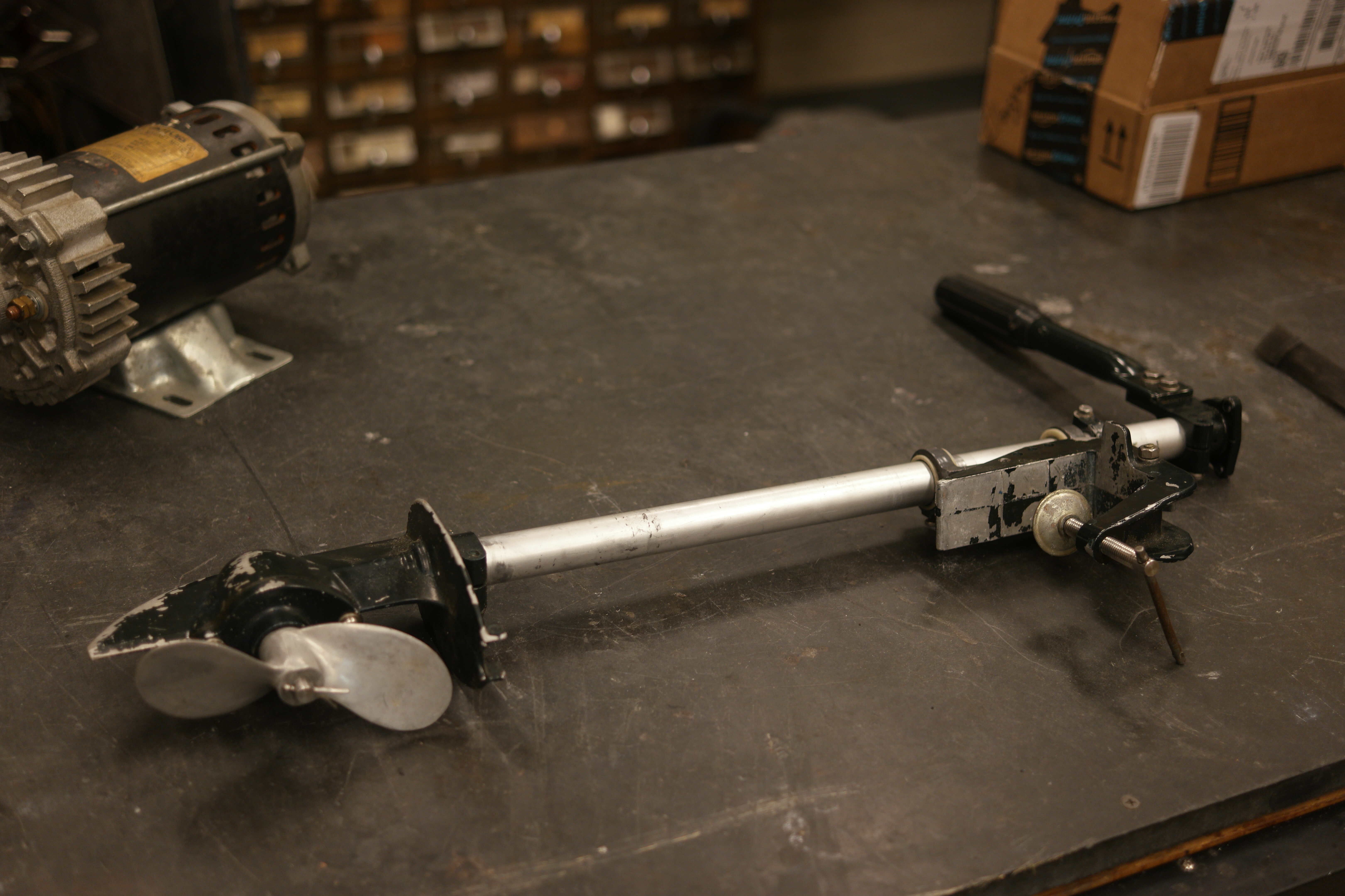

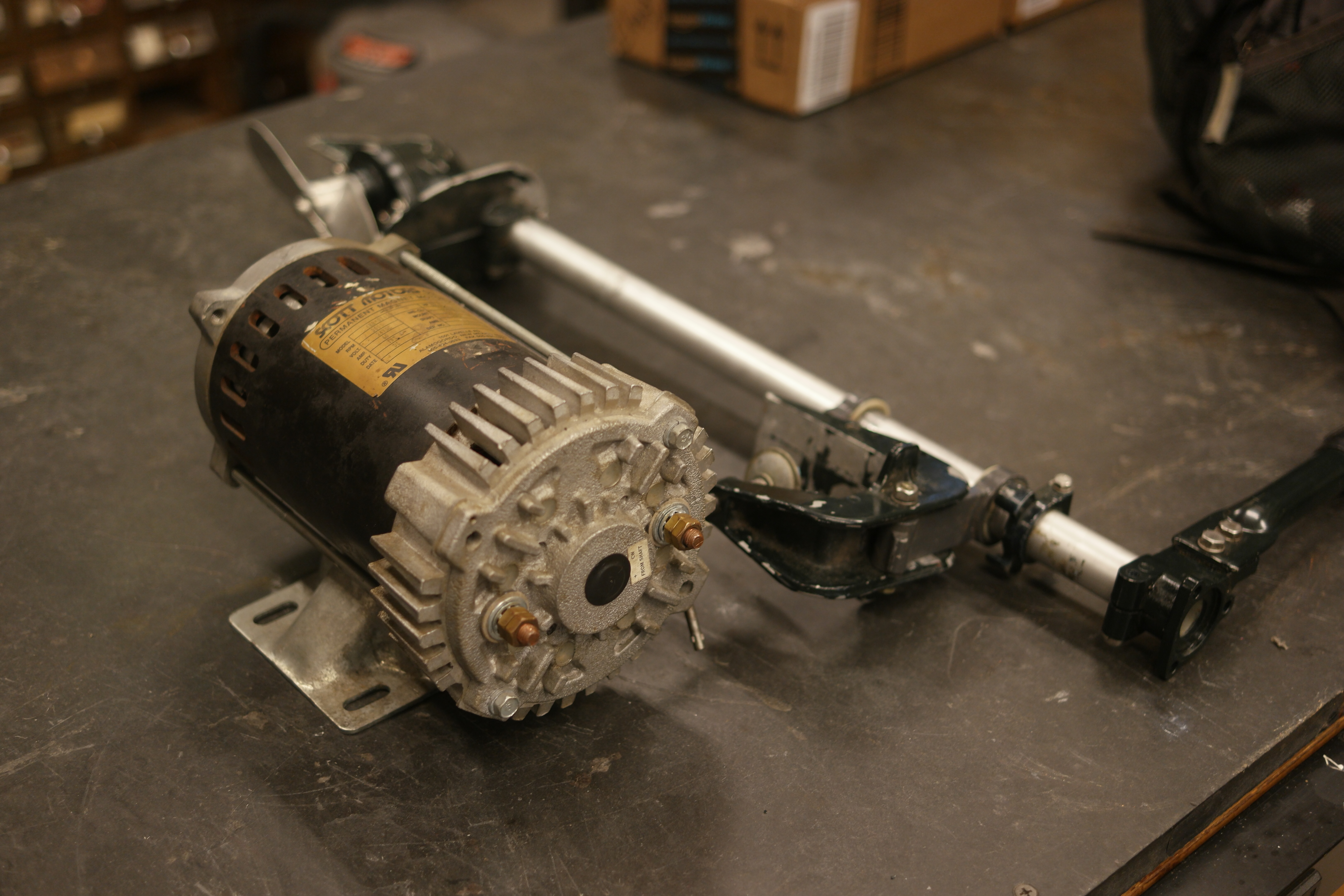
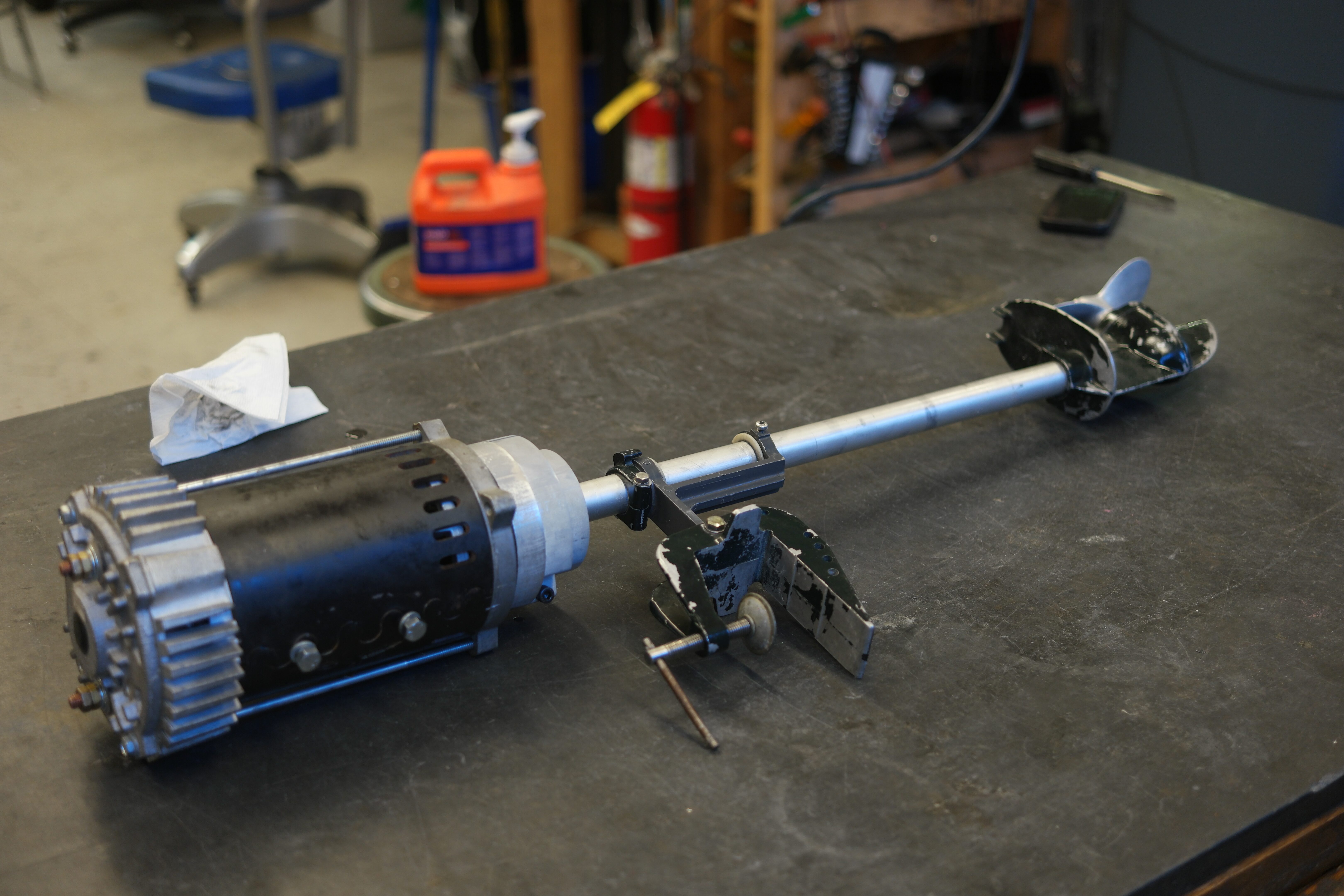
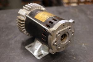
Electric Motor AdapterHere's the motor. The older cousin to the 'Black Max' dc brush motor used in everything from floor scrubbers to combat robots, its a SCOTT MOTORS pump motor, rated at 28v 40A, or 1hp. Because its a pump motor it has a strange housing with an inset shaft. Pump assemblies apparently bolt directly to the motor. Admittedly this makes it a bit more difficult to use in shaft-driven-thing applications, but lathes are our friends and adapters can be fashioned. 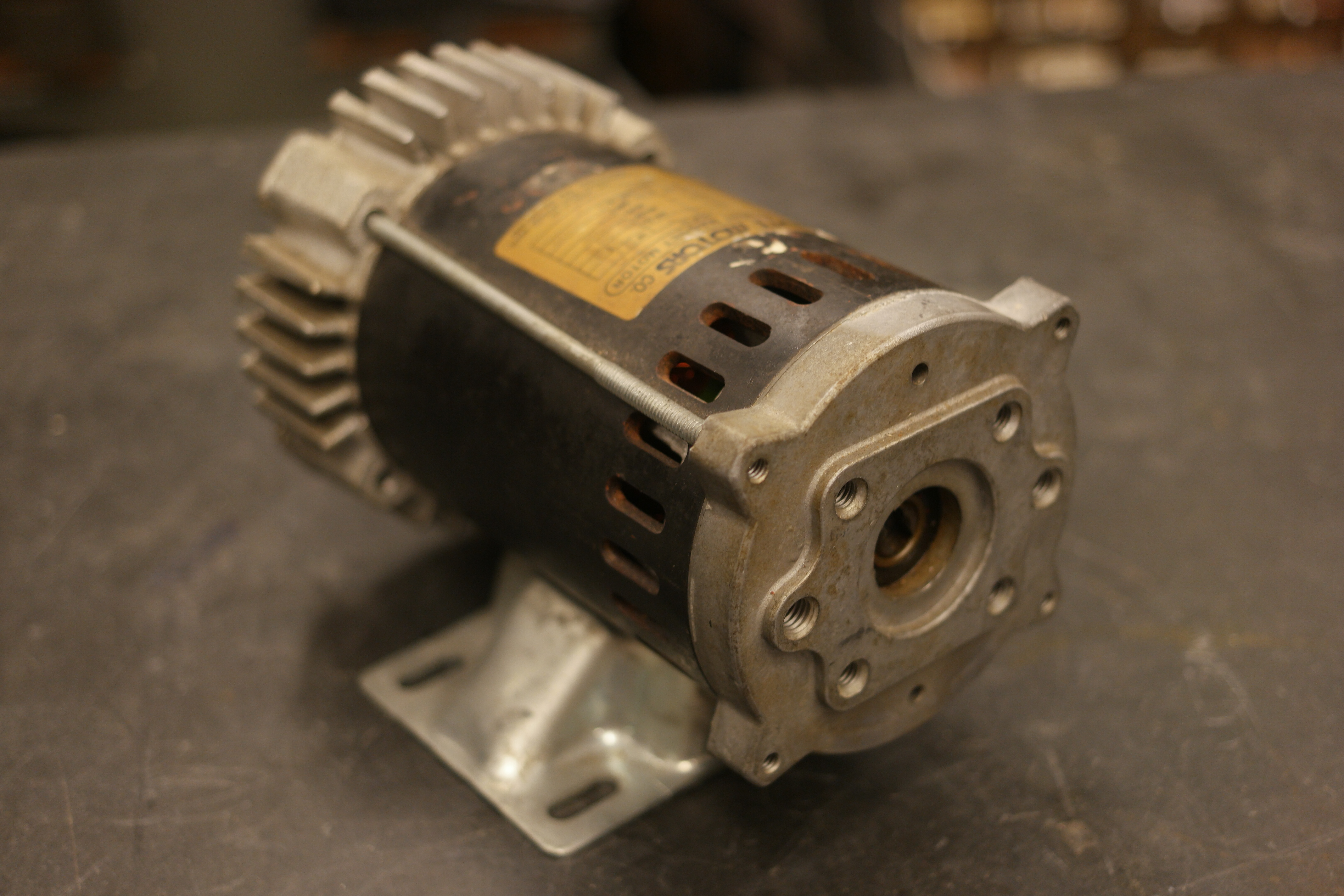
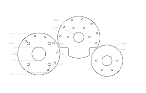
Lets make an adapter. Here's the front face of the motor, after some quick calipering and sketching an adapter was designed. Using three plates of 3/4" thick aluminum we'd capture a flanged bearing, and still be able to clamp onto the existing outboard base mount. 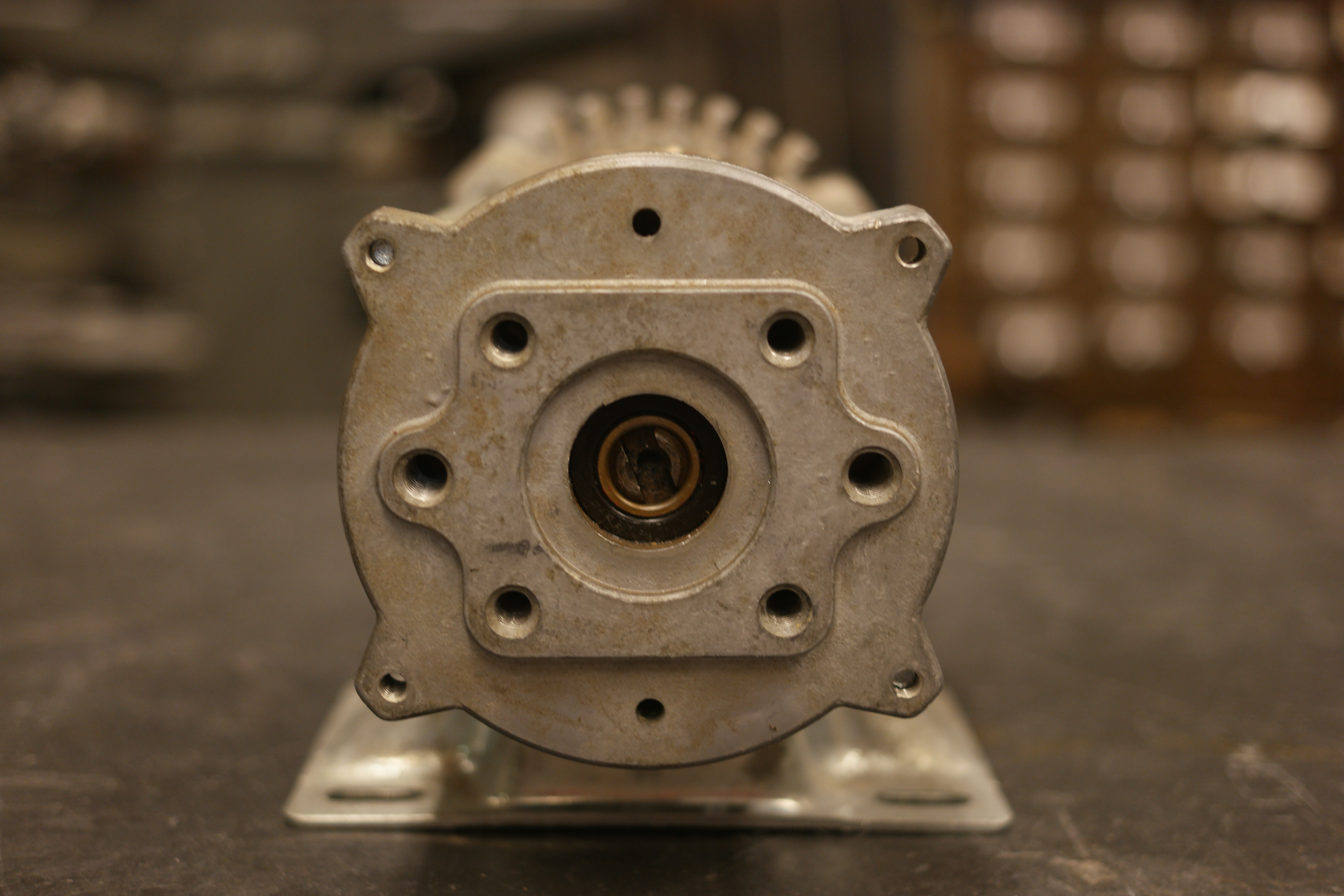
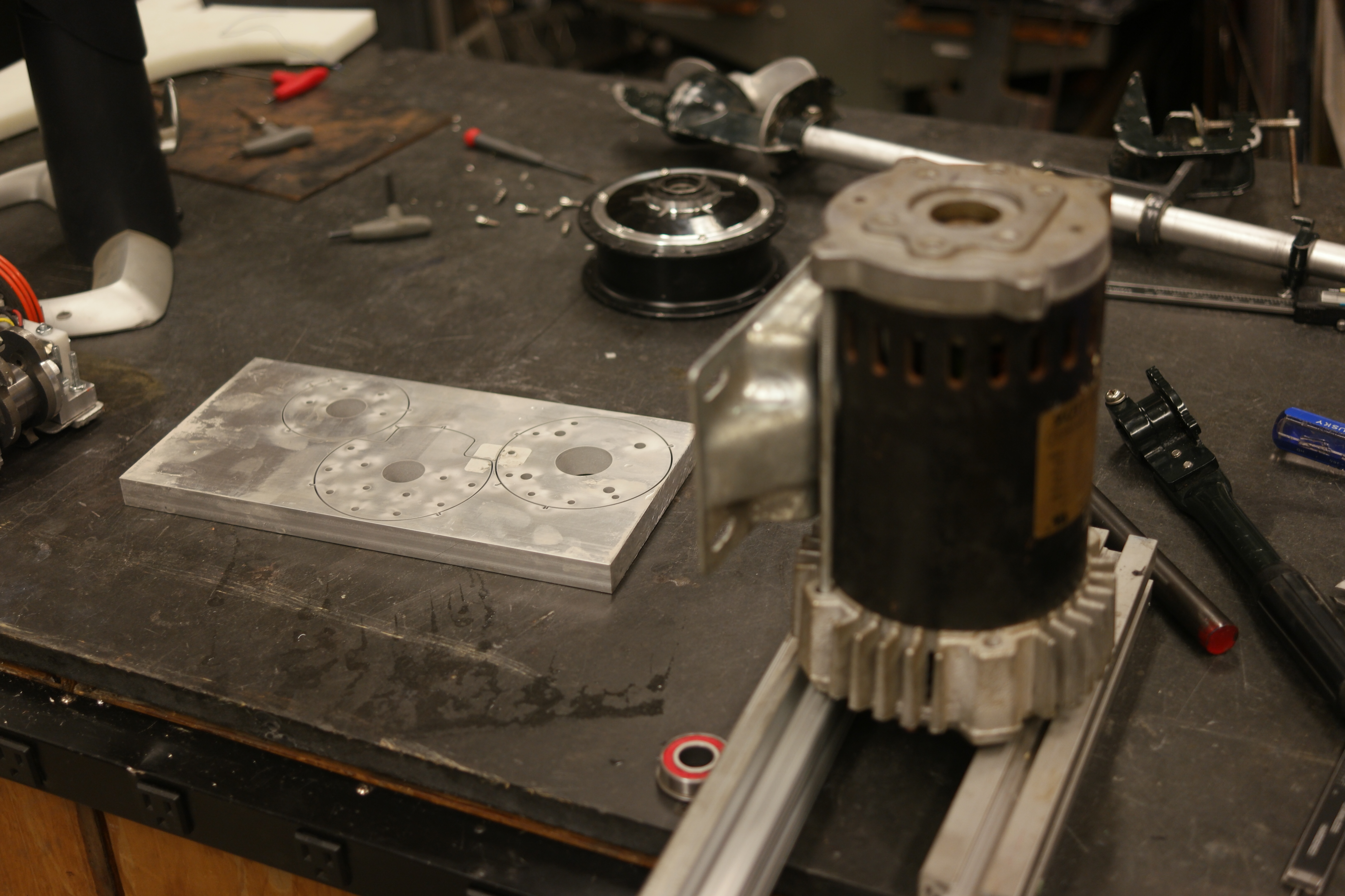
Off to solidworks. The adapter is shown, and the design files [Solidworks 2014] are included below. 
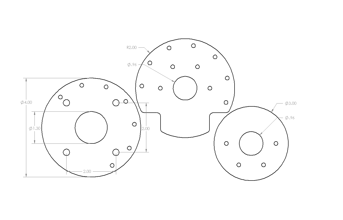
Magical Waterjets. The 3/4 inch thick stock itself was scrap that was leftover, the N52 jet had no trouble chewing through the relatively thick material. 

And the turning begins. After some quick boring bar action, a flanged bearing slid right into place on the inner bearing mount. I used steel shaft, milled with a flat matching groove, to mate to the motor itself. This was used for positioning as well for the mating motor hardware. 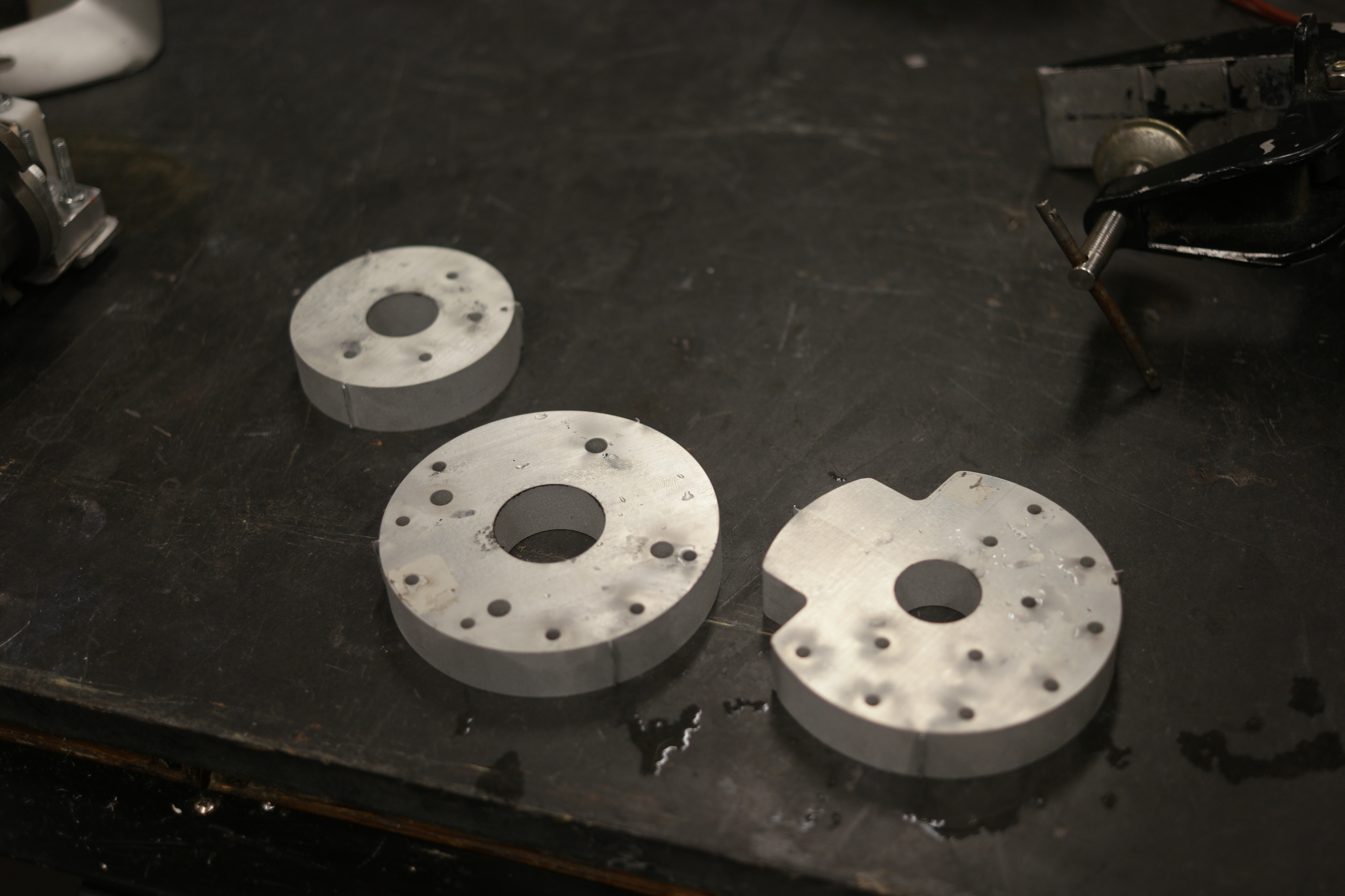
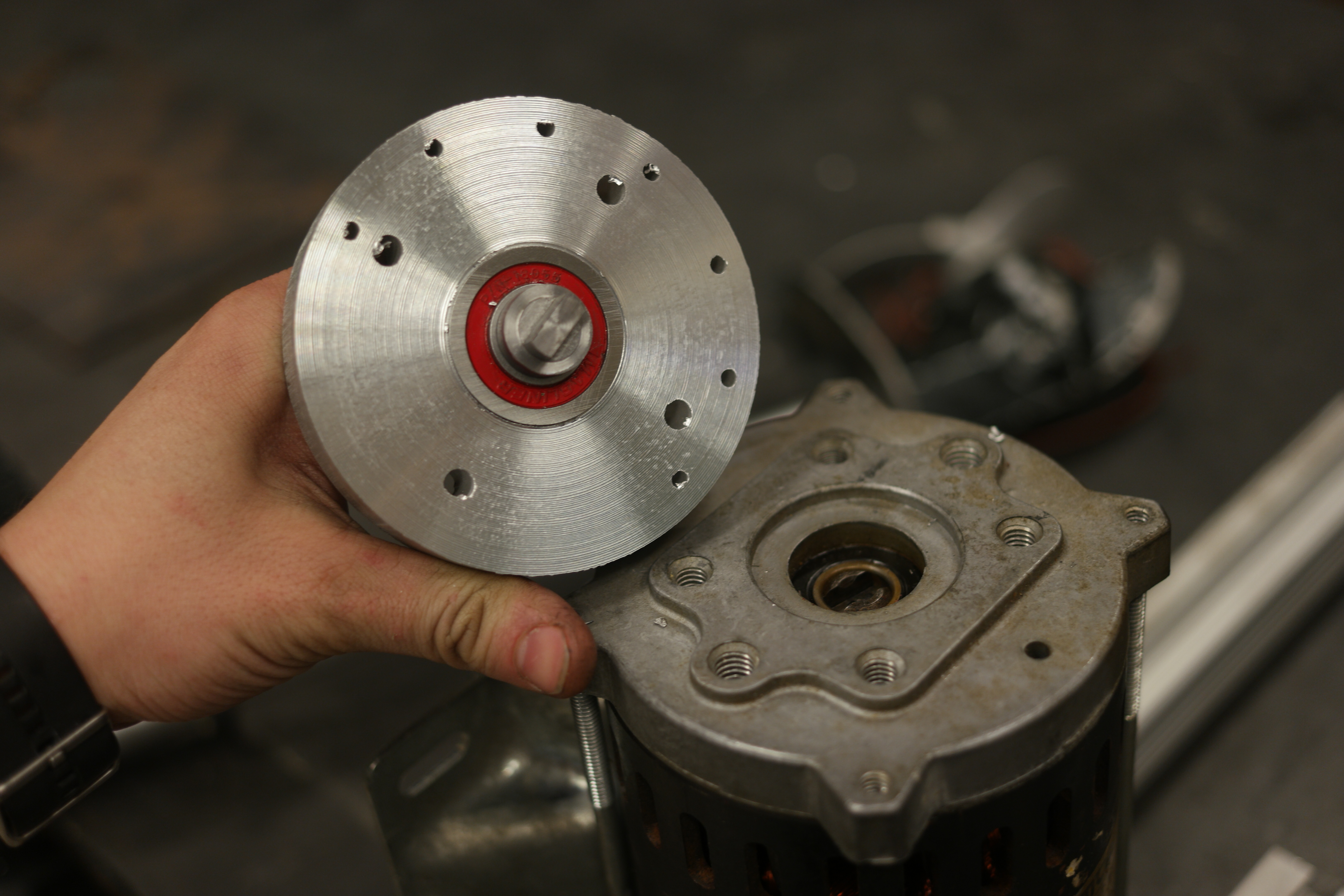
Using a Bridgeport milling machine, inset holes were added for the socket head bolts, including space for the sockets. This captures the hardware used for the motor mount. As this is a vibrating environment medium loctite was used to help prevent decoupling of the motor and the mount. An opposing flanged bearing was added to keep the shaft co-linear with the surface. 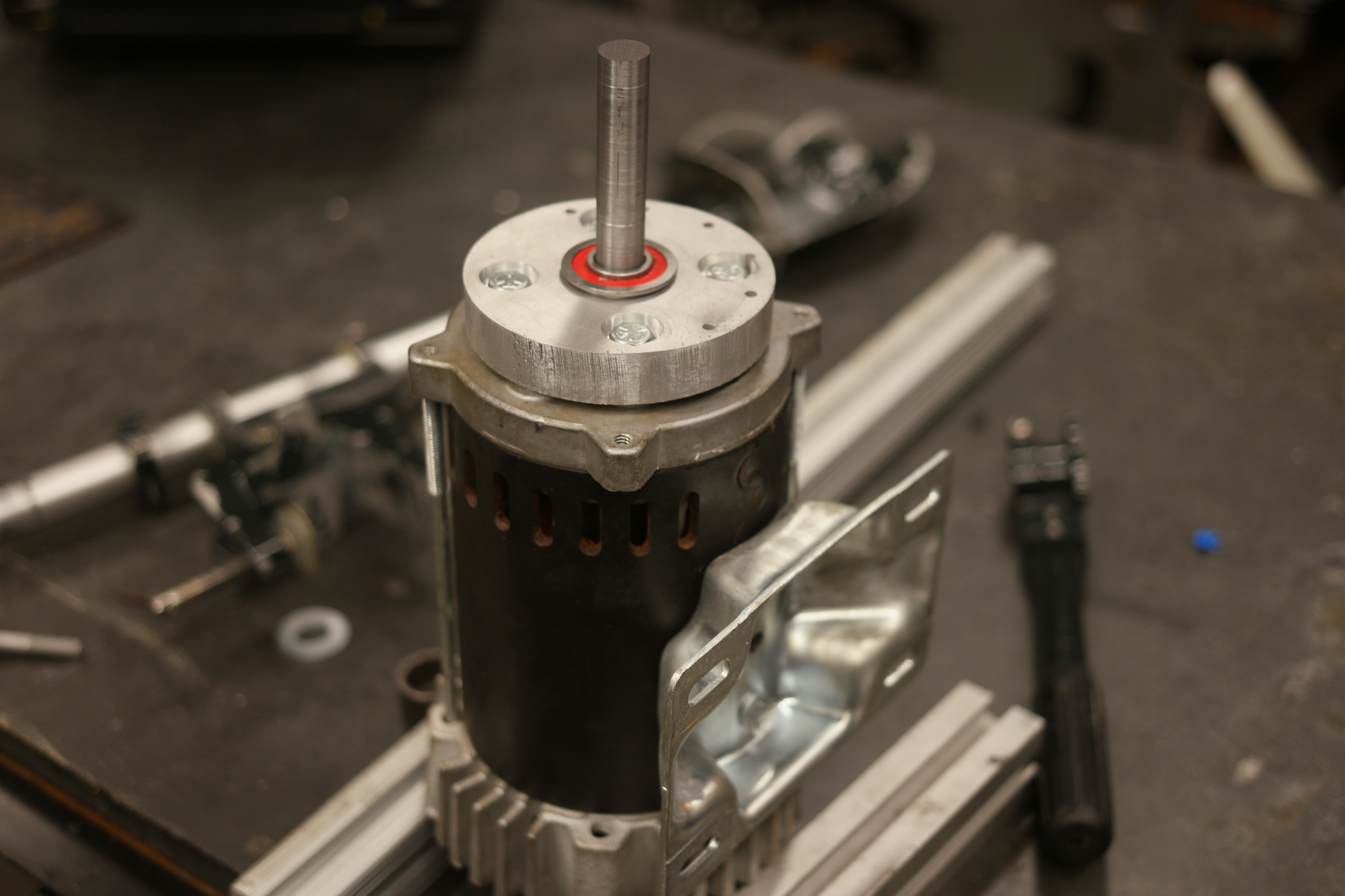
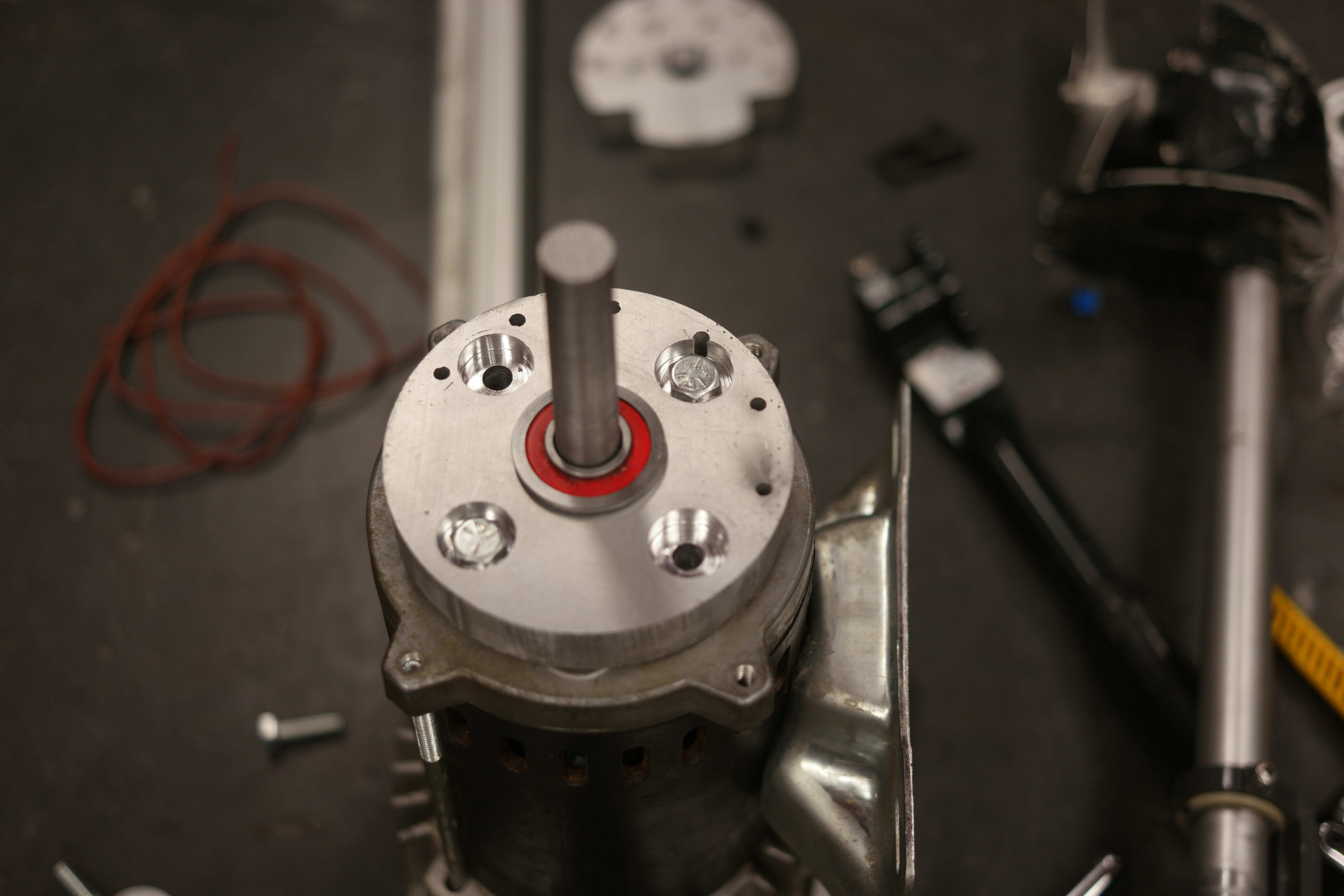
Shaft features. the shaft itself started as a center-drilled hole with a slot added in to match the opposing feature inside of the outboard. The shaft diameter was turned to fit the flange bearings on hand, with the exception of the very top area which features a retaining ring to constrain the shaft to live inside the captured motor-adapter area. 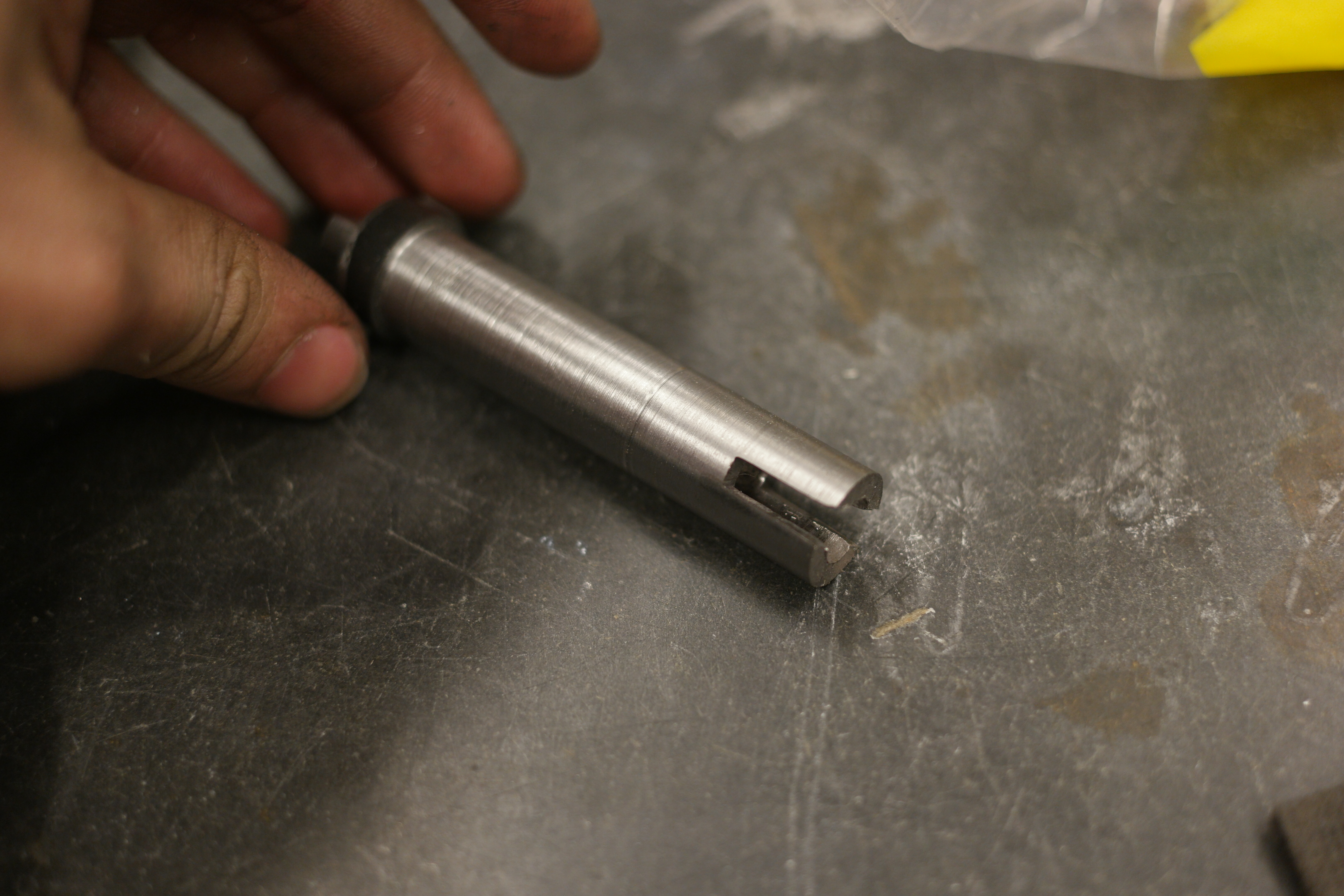

All buttoned up, the motor-shaft adapter came together quickly, a small amount of spring steel-shim-stock was added in the motor inset groove to keep the assembly under tension while assembling. Note that the perimeter holes are tapped such that the next part (outboard shaft clamp) can mate to the motor. The mating holes are only on one side as the clamp applies pressure by use of a flexure. 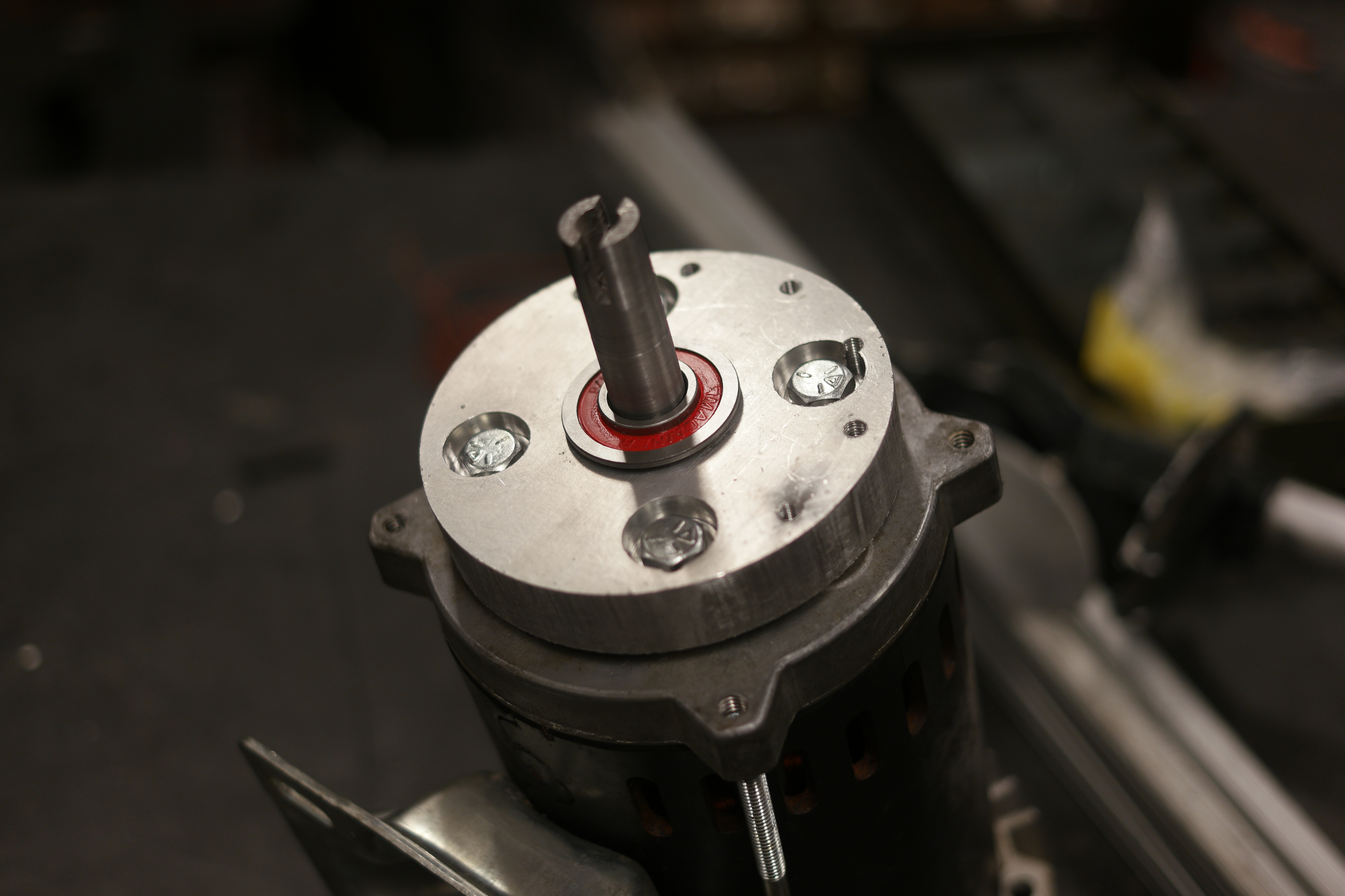

The flexure and the retaining ring bolt onto the motor directly. The two parts are stacked to provide more surface area for the motor assembly to mate to the outboard. I was mildly concerned that if one section sat as the clamping surface it would kink or apply too much force to the outboard. The length of the motor shaft was tailored to the distance the internal outboard mate was. All in all it fit! 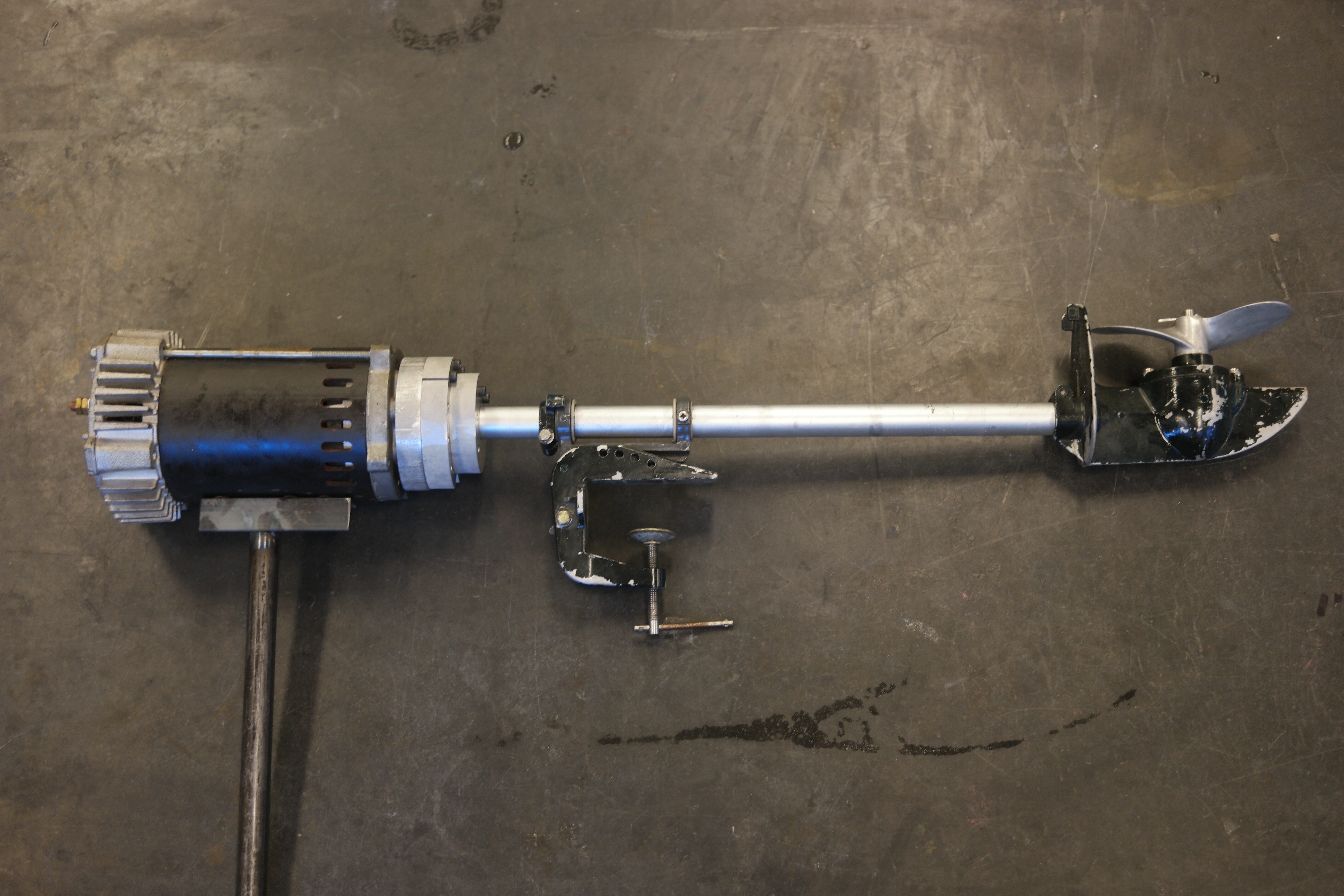
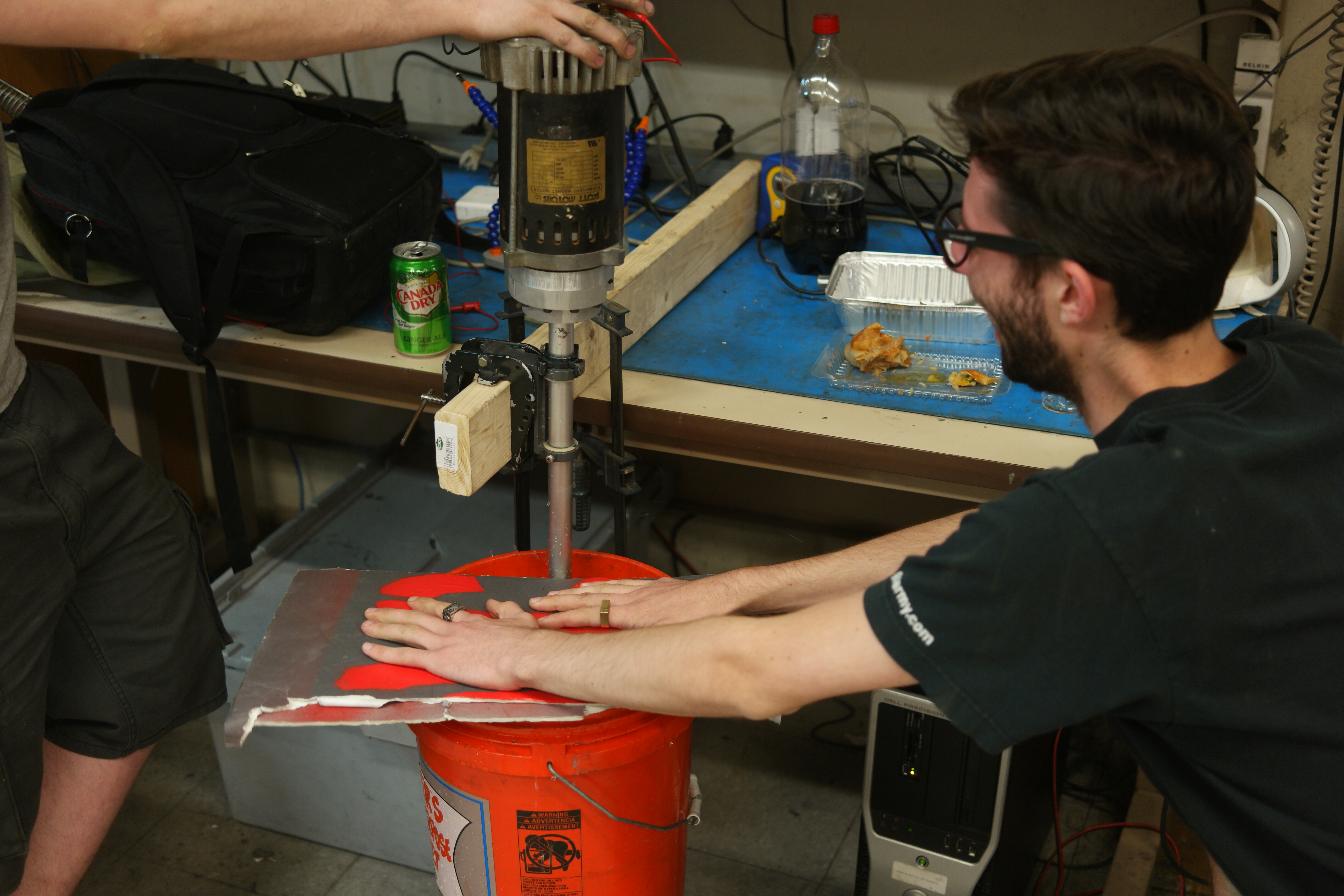
Bench Test → Endurance TestExcitedly the prop was shoved in a bucket and the motor was spooled up, splashing everywhere occurred. 
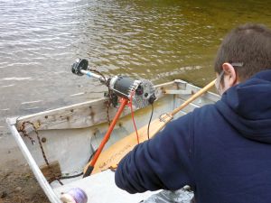
Next up, Myself Birkel and Ciarian headed west to test the brand new contraption out on some fresh water. To power the craft we ended up using (effectively) a 12S LiFePO4 pack (40v nominal). This was controlled with a 200A DC circuit breaker switch, no motor controller was used otherwise. The boat is an 8' JON BOAT, aluminum extrusion which weighs about 60lbs and fits three folks if they get friendly. 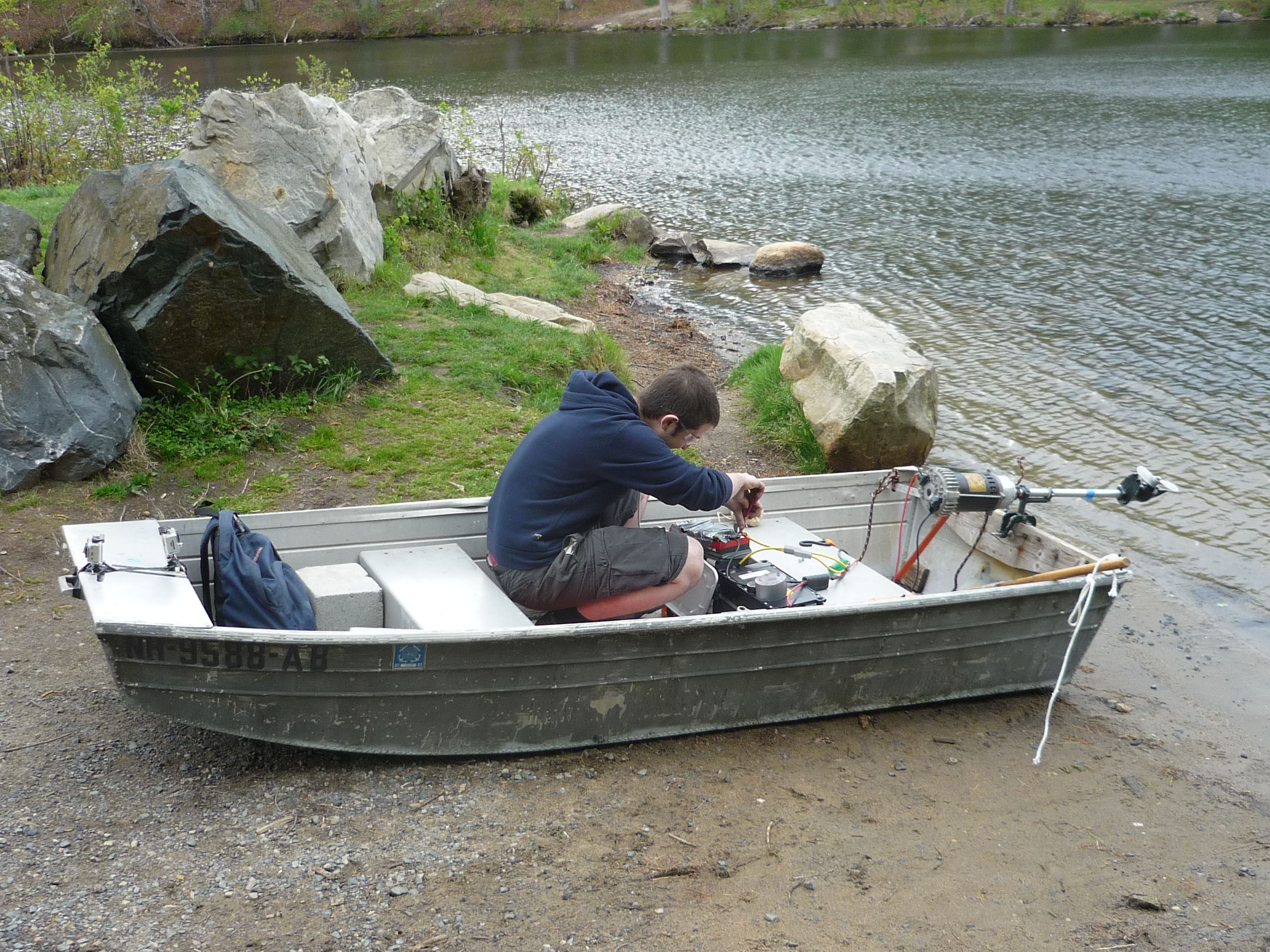
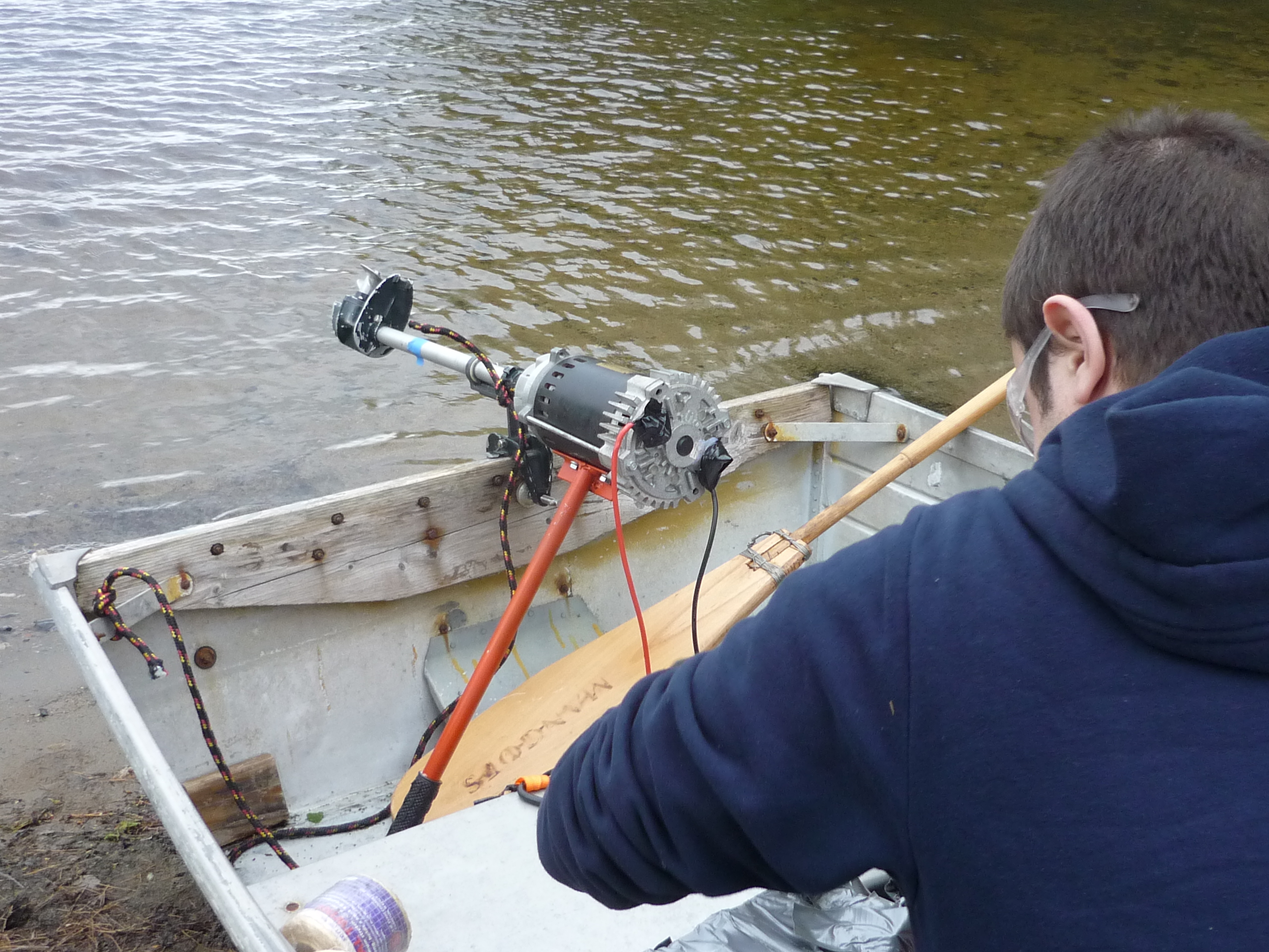
So we let birkel test it out first and lo, it worked. Initial tests were at 8S LiFePO4 (28V), but looking at the in-line watt-meter we were only pulling 30A, i ran back and grabbed a 4S pack and hastily added it in series. With 40v we now had quite a bit more pep and we were off to do a stress-test. 

The Endurance TestImportant to note, the craft had 3 people and a fairly large battery array onboard we were moving at roughly 6mph across the water, which was fairly excellent given how much surface area we were taking up in the water. The outboard held up well and got us to / from the island without too much hassle. SuccessDC thruster kept us moving along, we made it to our target destination. 
A small foldable stove was used in an existing fire pit to warm up some water for tea, 'success' tea was had and we headed back for the shore afterwards. 

The skies were gorgeous as the sun set. Haistly assembled projects have some side benefits, namely excellent views! 

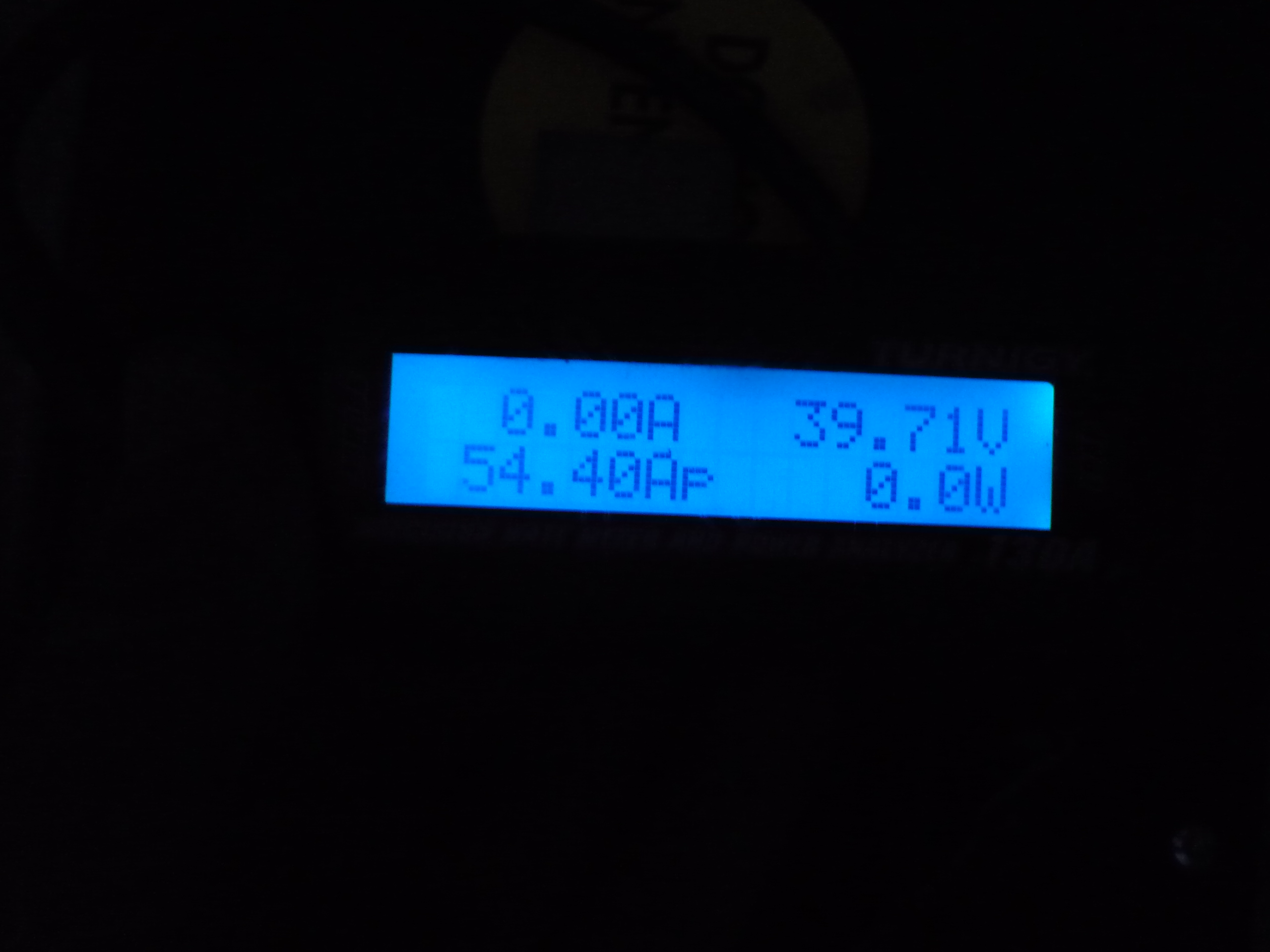
In total we pulled 11.8Ah traveling about 2.1 miles and testing the motor out with variable amounts of people / stuff. Peak current was 54.4A, but it nominally hovered around 40A. This was measured using a HV turnigy 130A watt-meter. 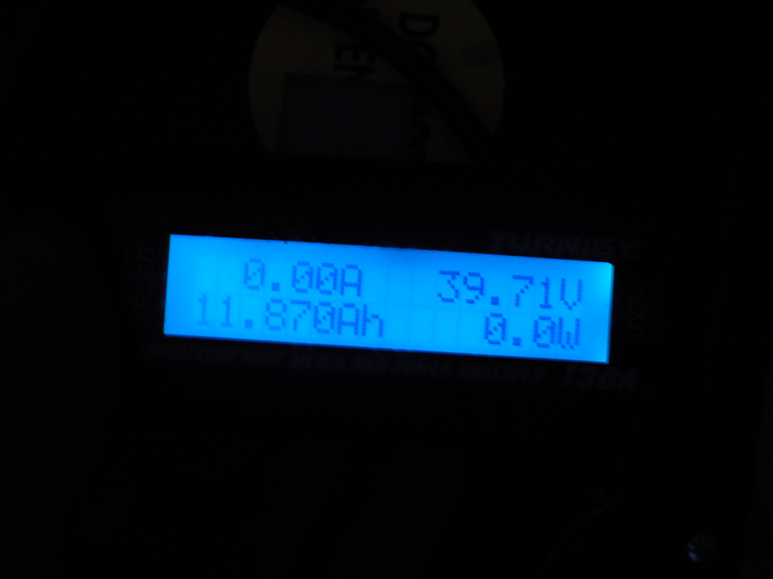
Concluding Remarks
If you have questions or comments, ask below or send over an email. (be careful, im not responsible for incredibly warm DC power cabling )
Have you noticed that there are no advertisements or ridiculous pop ups?
Want More?
|
Post your comments! |
|
Comment Box loading
|