Dane.Kouttron
[4.12.14] Submersible Thruster
Testing: 3 Phase Liquid Cooled Propulsion
What?
How
much force can a submersible thruster generate? How can you measure it
without a full aquatic lab? This page documents experimental testing of
the submersible thruster MK-01. Design and fabrication of the thruster
is listed here,
take a gander for some details!
|
 |
 |
 |
| Thruster,
water, springtime |
|
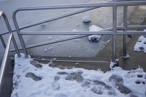
The ice has receded, and is no
longer available
for scootering on. The resoviour was ready for some static
submersible thruster testing!
Using
a cheap strain gague, some aluminum tubing and a pile of ring-clamps,
data was acquired indicating force vs watts (input). Using that data, a
dynamic test rig was built to study dynamic operation and to stress
test:
* Shaft seal
operation
* Three phase motor
* Motor controller
temperature vs time
* Torque and force
produced on impulse loading.
Bring a paddle, pdf and spare batteries. Enjoy!
Testing Video Below |
|
| Initial Force vs Thrust Test Setup
|
|
|
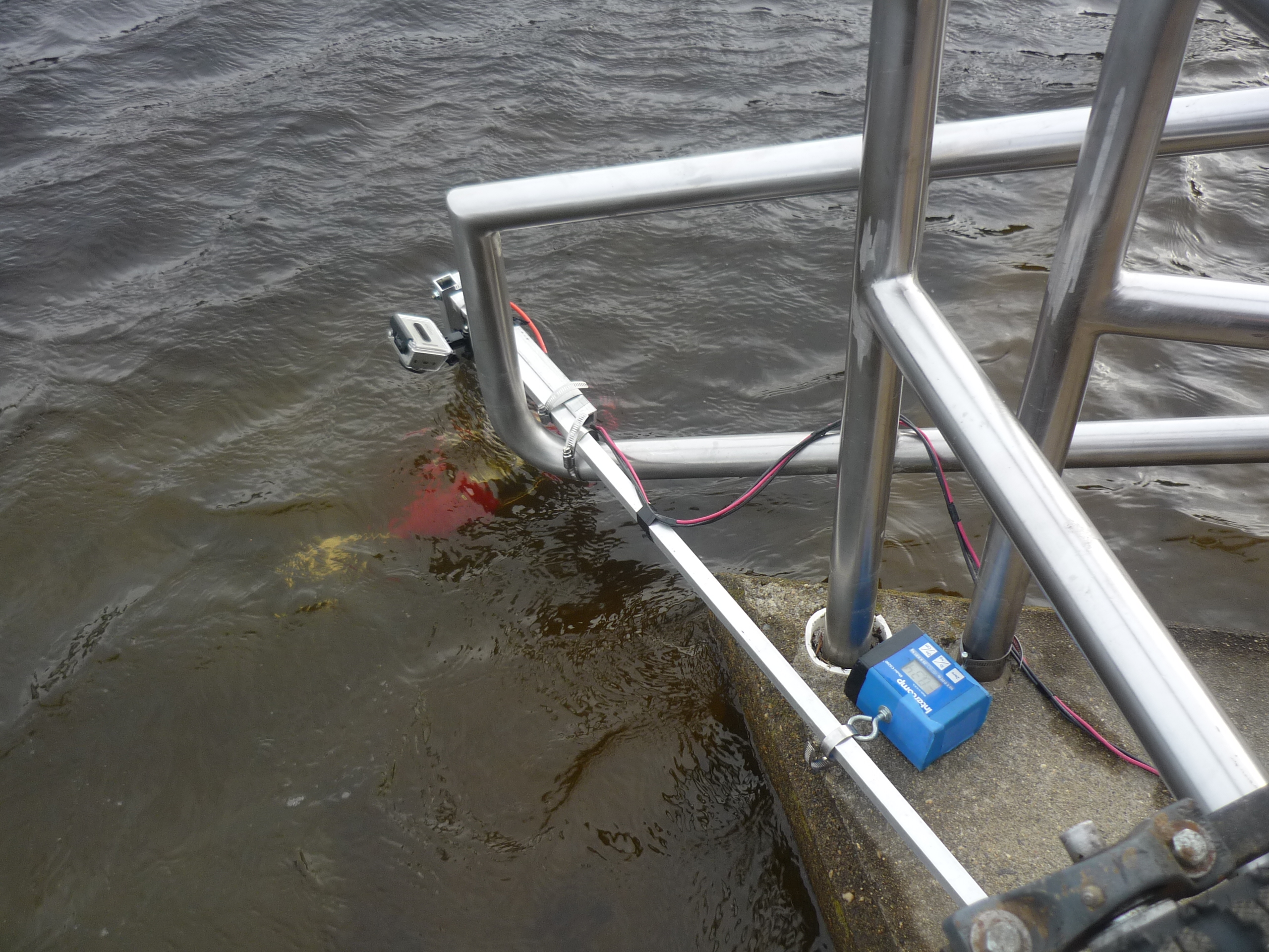
| Initially
I had wanted a ballpark force value for the thruster, was it 10
lbs-force? 50? 100? While in simulation it was designed to
prevent cavitation at ~2.2k rpm, I needed a boundary to define how the
thruster mounted to the canoe-contraption. To do this, in a
quick-ballpark fashion, i used some square aluminum tubing, ring clamps
and a very basic electronic 'fish' scale. The scale I had on hand was
only 50lb rated, so I took advantage of a lever-arm to get more useful
range out of the scale. |
 |
|
Winter
Testing?
Initially,
I had the brilliant plan of testing the thruster towards the end of the
winter season. After getting out to the ice and determining that it was
too thick to cut with a simple harborfreight single-ended hacksaw, i
took some measurements and made sketches of a test rig for the warmer
weather. |
 |
 |
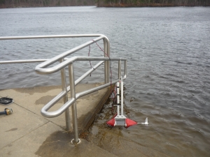
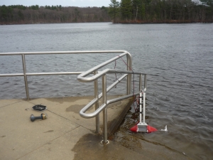
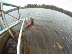
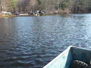
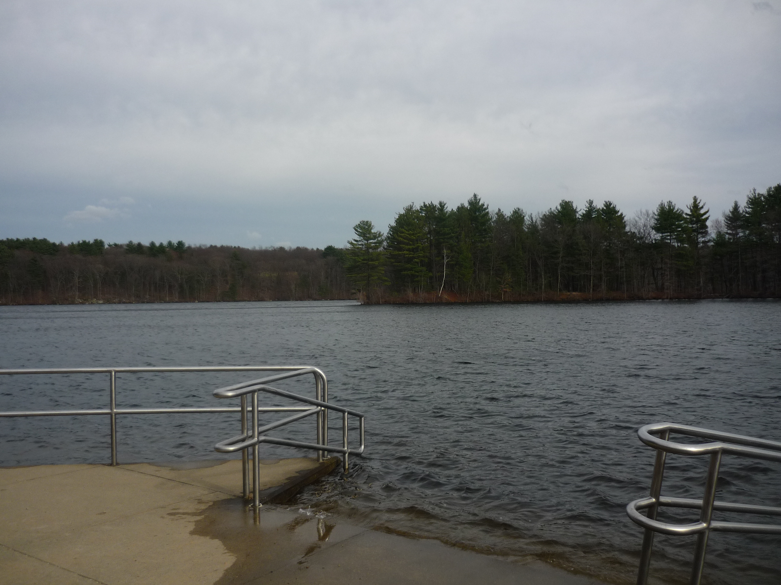
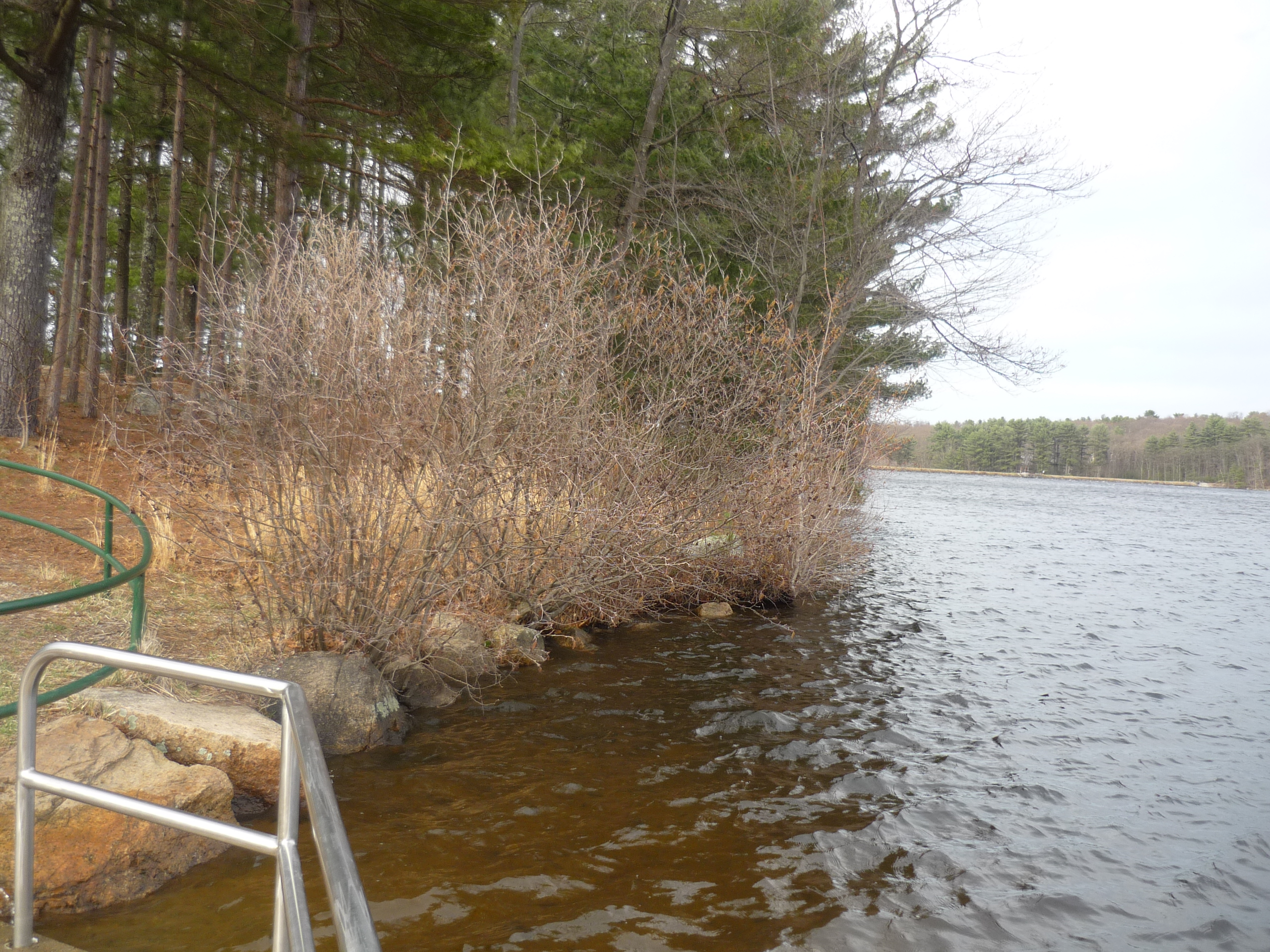
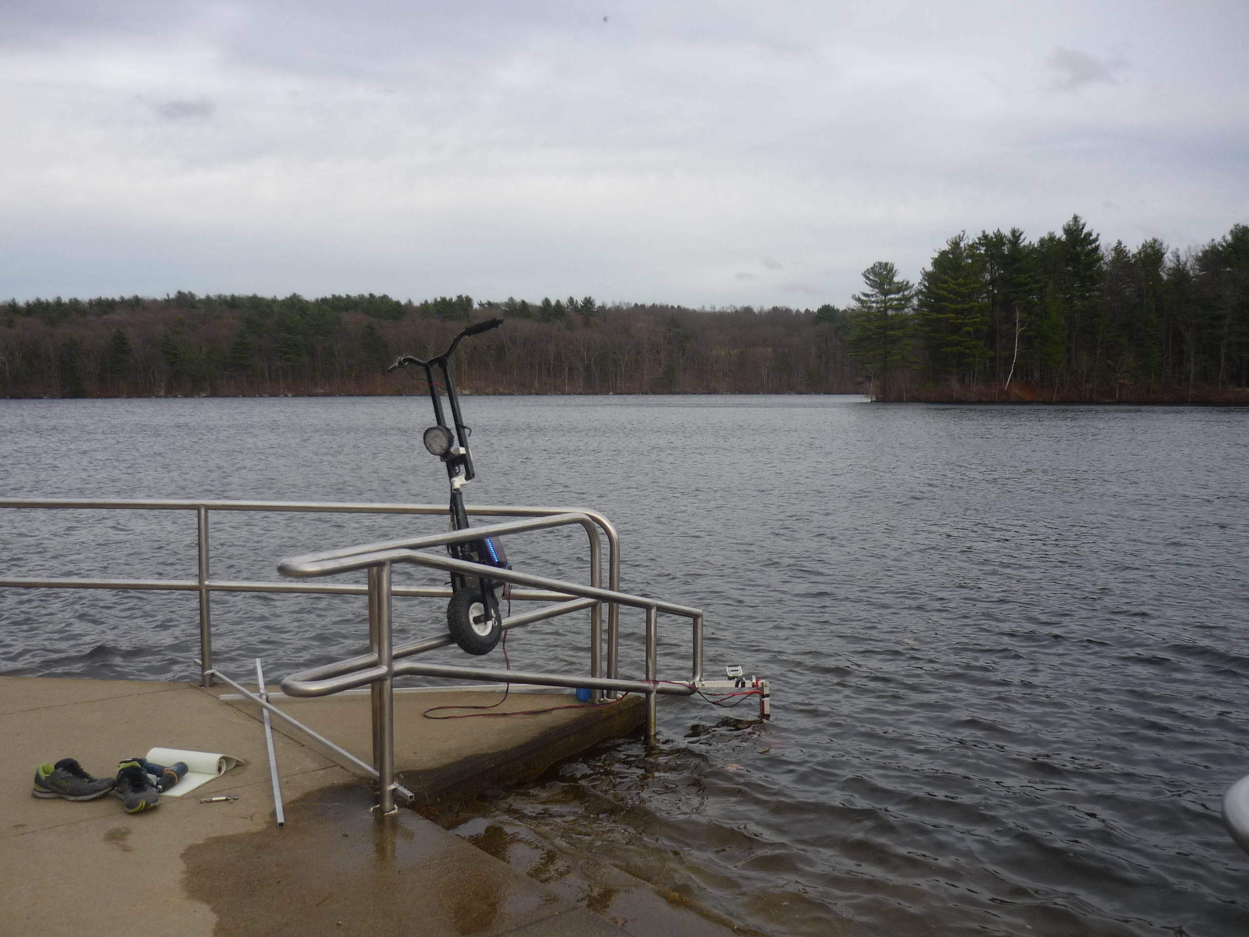
An
interesting setup at an interesting place
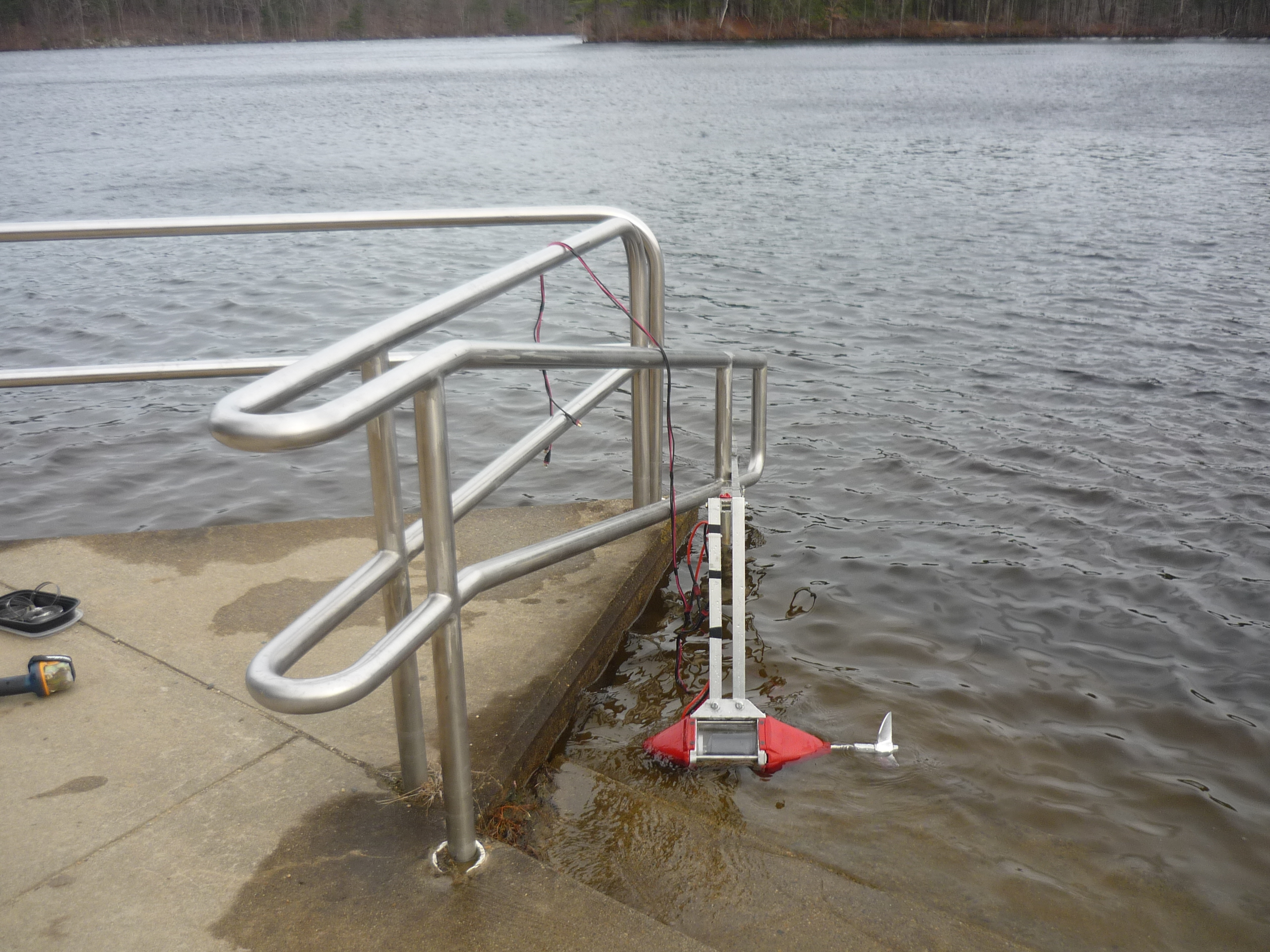
To
do this quickly, i took advantage of a handle-ramp area at a local park
to use as part of the pivot point for the measurements. Unfortunately
during testing my 'swapfest' camera took a plunge in the water, so some
photos are from the gopro directly. The railing sits
approximately 4 inches from the resoviour surface, and at that point
the water depth is roughly 1.5 ft. Note on the day of testing, the
water temperature was in the mid 30s (F), so standing in it for
extended periods of time was unadvisable. |
 |
 |
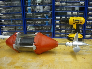
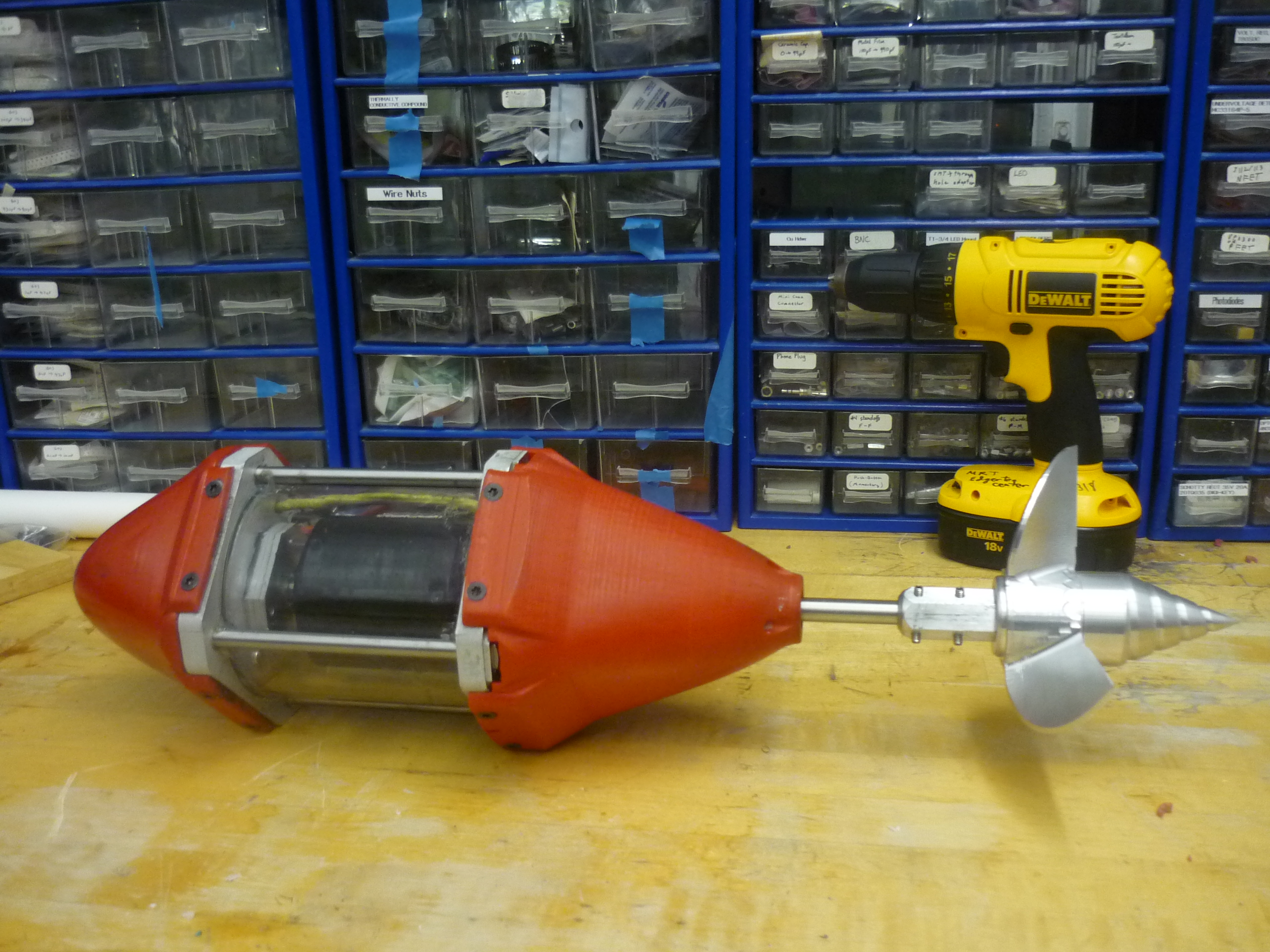
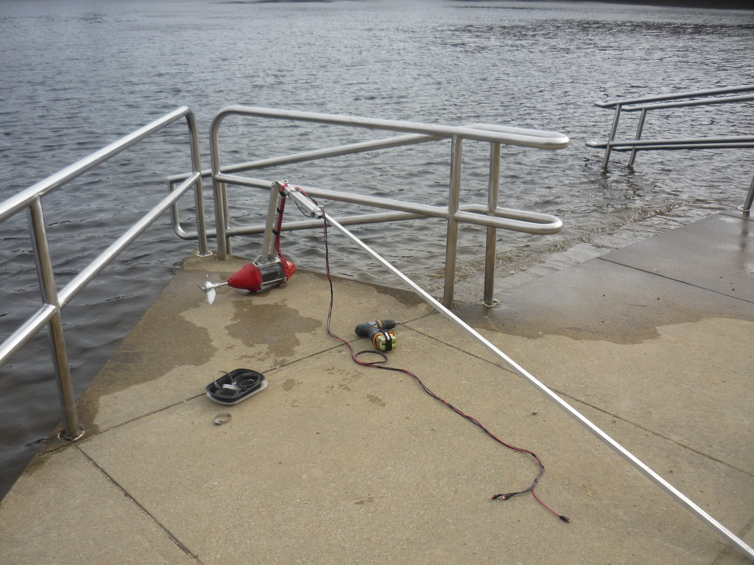
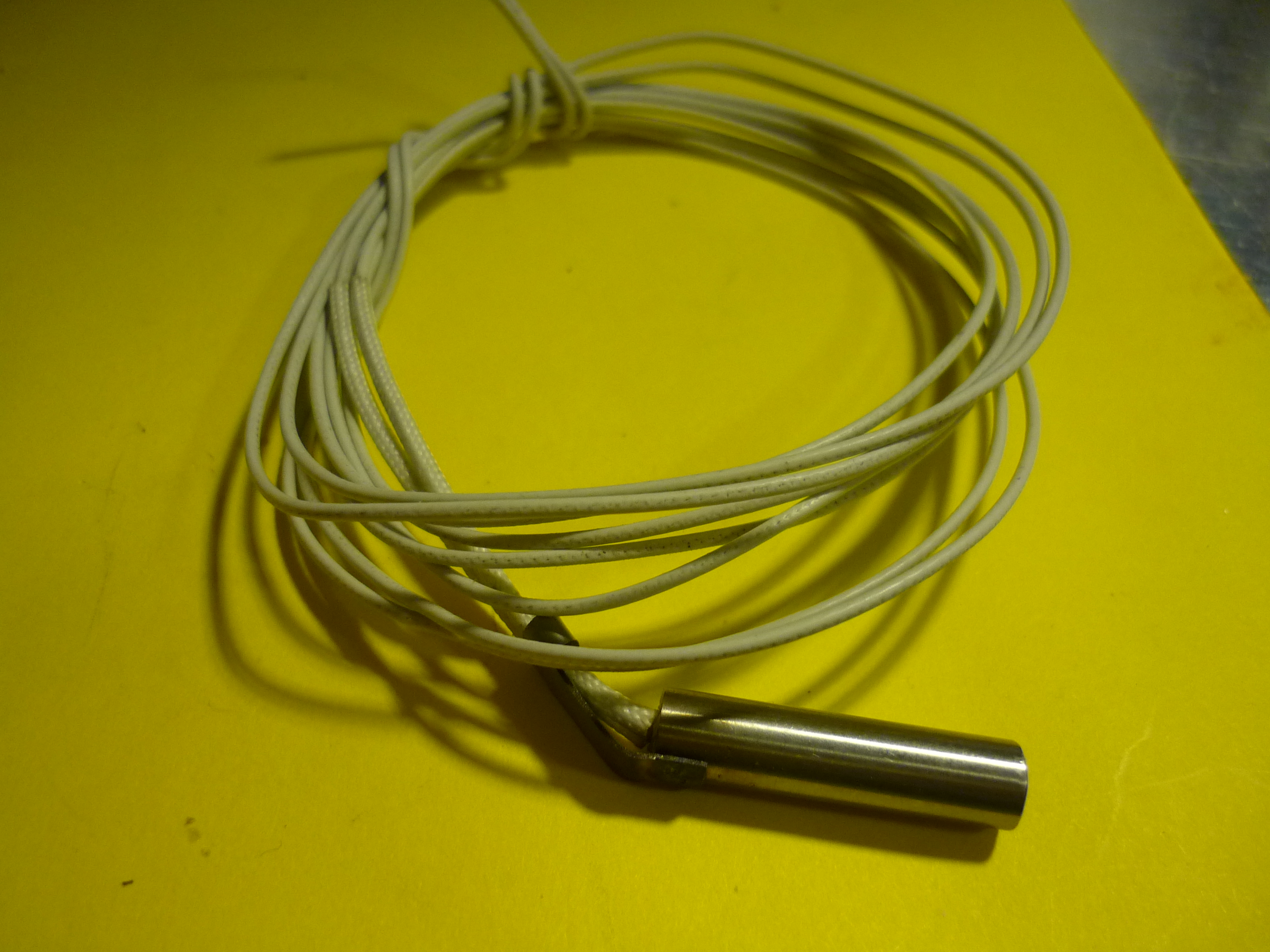
Motor
and 3phase extension cable
I started
with the lever-arm, and double-ring clamped the motor assembly to an 8'
long 1" square, 1/8th wall aluminum tube. Note the drill in the
picture, a hex-head adapter for the drill saved a lot of time zipping
the sections of tubing together. For this test, i fabricated a 3phase
extension cord from some donated 14 gaguer silicon wire. Note that 14
gague isnt really sufficient for the power requirements, but for pulse
loading it helped get the testing completed early. Multistrand silicon
wire is also great for these type of test, as its incredibly flexible. |
 |
 |
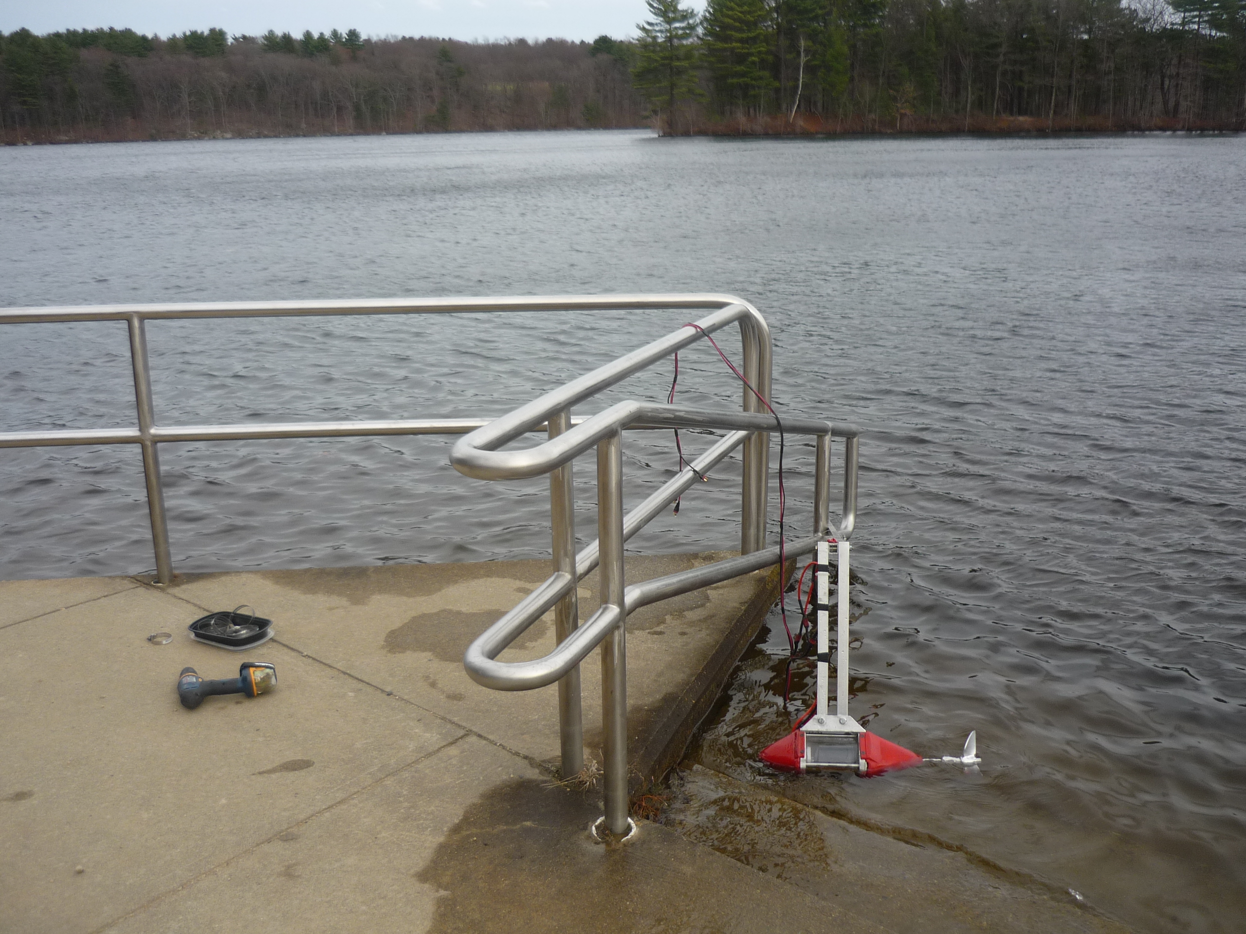
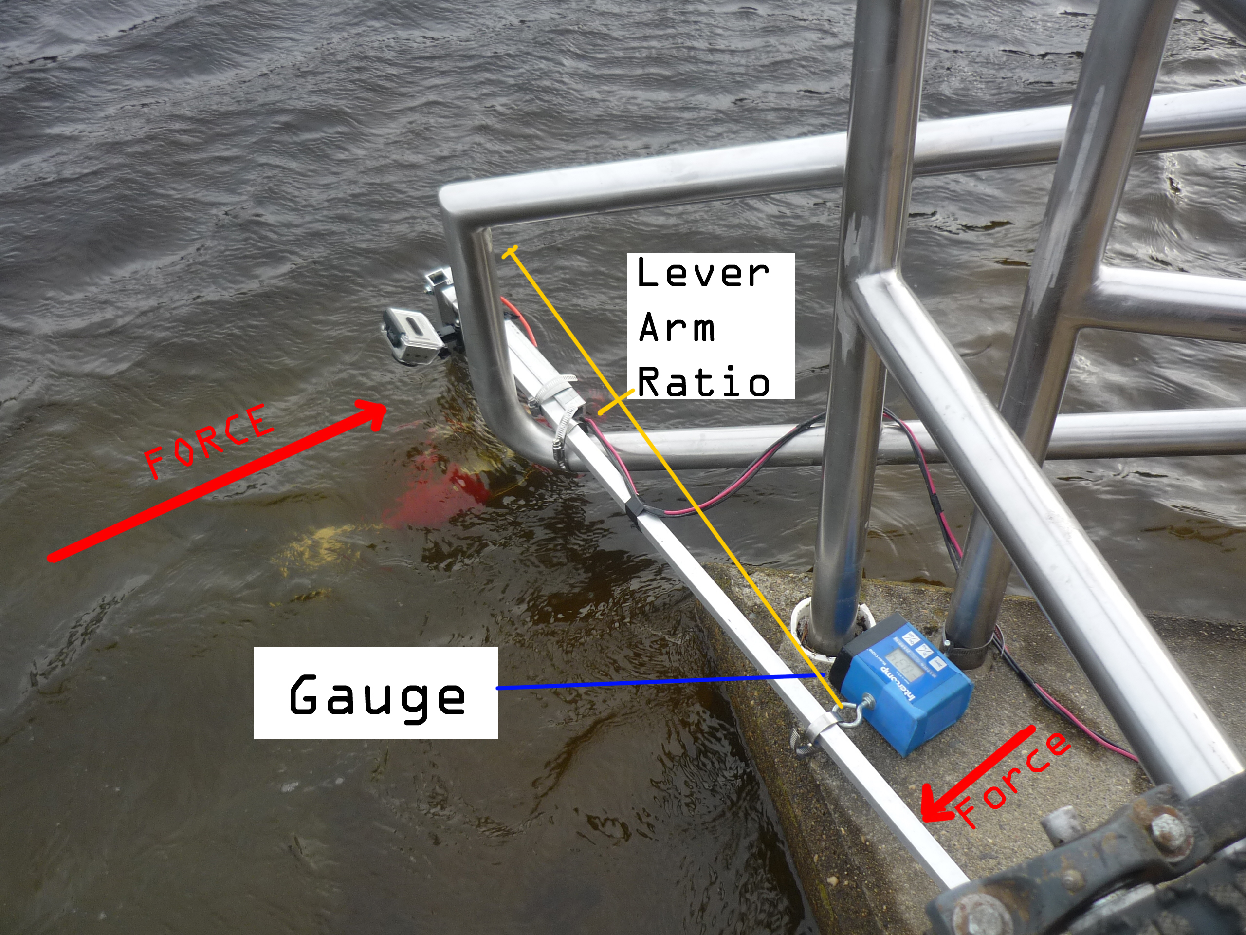
Lever
arms and scale
I
used a variable lever arm to determine a rough estimate of force
generation at different power levels.As the motor pushes forward, it
pulls against the lever arm the lever arm itself it sitting
between the concrete slab and a small aluminum guide. Static friction
in this test setup is fairly hight, however, and the lever arms
themselves are not static, and deform under test. |
 |
 |
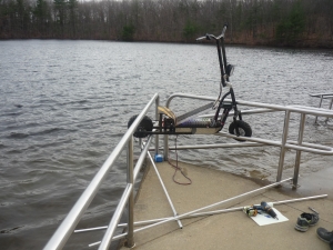
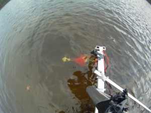
POWER
The
3phase drive from the electric scooter project was used to power this
test rig. To make it easier to operate the motor controller, observe
the watt-meter and observe the force gague, I located the scooter on
top of the railing assembly. This was a bit precarious, as it was a
windy day. A lab notebook (held down by a drill) was used to record
force / watt data. |
 |
 |
Video
Footage
was recored using a GOPRO HD Hero (circa 2010). Note that I purchased
this item third hand and this was the first test of its functionality
underwater. It worked great! Note that the mount was ring clamped and
electrical taped in place to prevent it falling into the resovour. |
|
 |
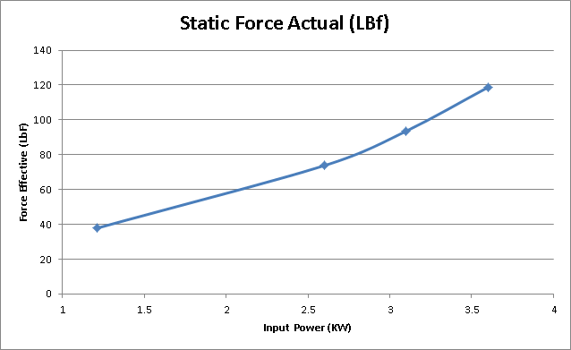
| Data
|
|
So what was that notebook for? ITS FOR SCIENCE
There was a great quote from mythbusters [link]
regarding science and lab notebooks, and it does hold true! I recorded
rough power vs force measurements during testing, unfortunately this
required jotting down data hurriedly while manipulating throttle and
keeping one hand on the circuit breaker/off switch. During testing a
couple walked by with their dog, and concernedly asked what I was up
to, grabbing a lab notebook with data convinced them I wasnt up to
anything nefarious.
118 pounds-force is a lot of thrust
for a homemade contraption, with a mathematically designed propeller.
While i am a bit skeptical on how it was that high (test setup
innacuracy, strain gague accuracy) it was visibly twisting aluminum
extrusions without much effort. There is a list of 'trolling motor'
sizes for various crafts [link]
and ~100lbs-force of thrust is sufficient to move a 4000lb vessel,
albeit slowly. fancy expensive trolling motors put out roughly half as
much thrust [link].
Note that had i continued (with a larger controller) to increase power,
the static force should beging to fall off, as the relationship is
fairly nonlinear [pdf link]. |
 |
| Testing on a small boat
|
|
|
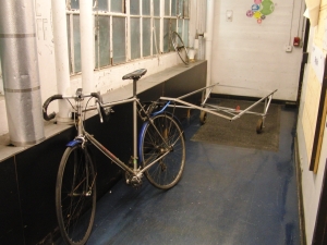
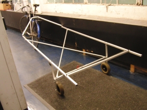
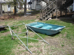
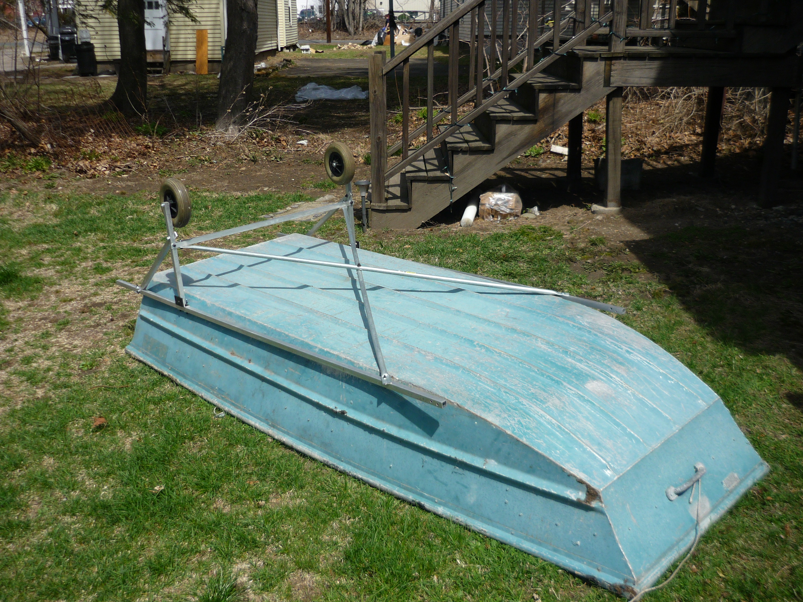
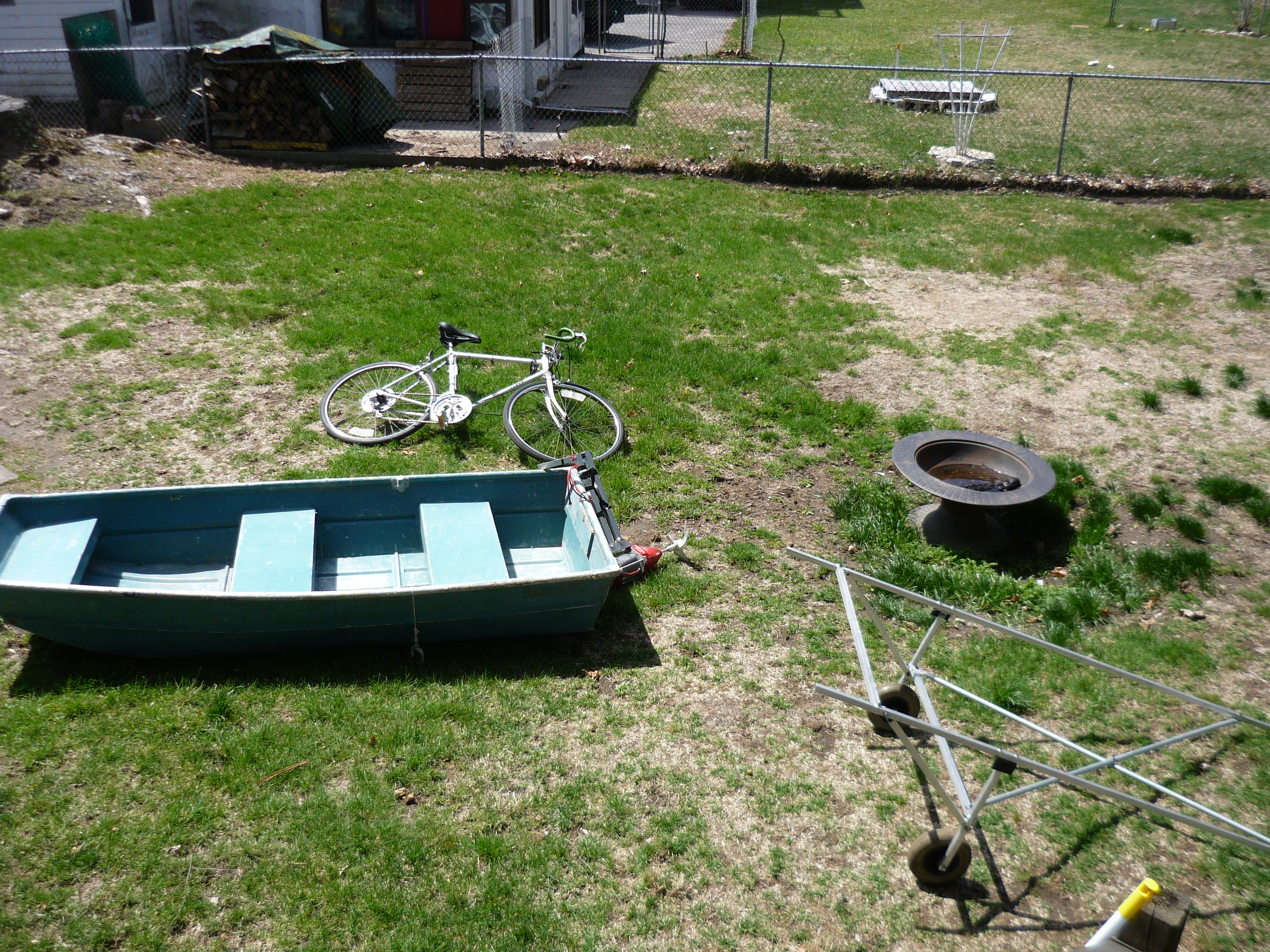
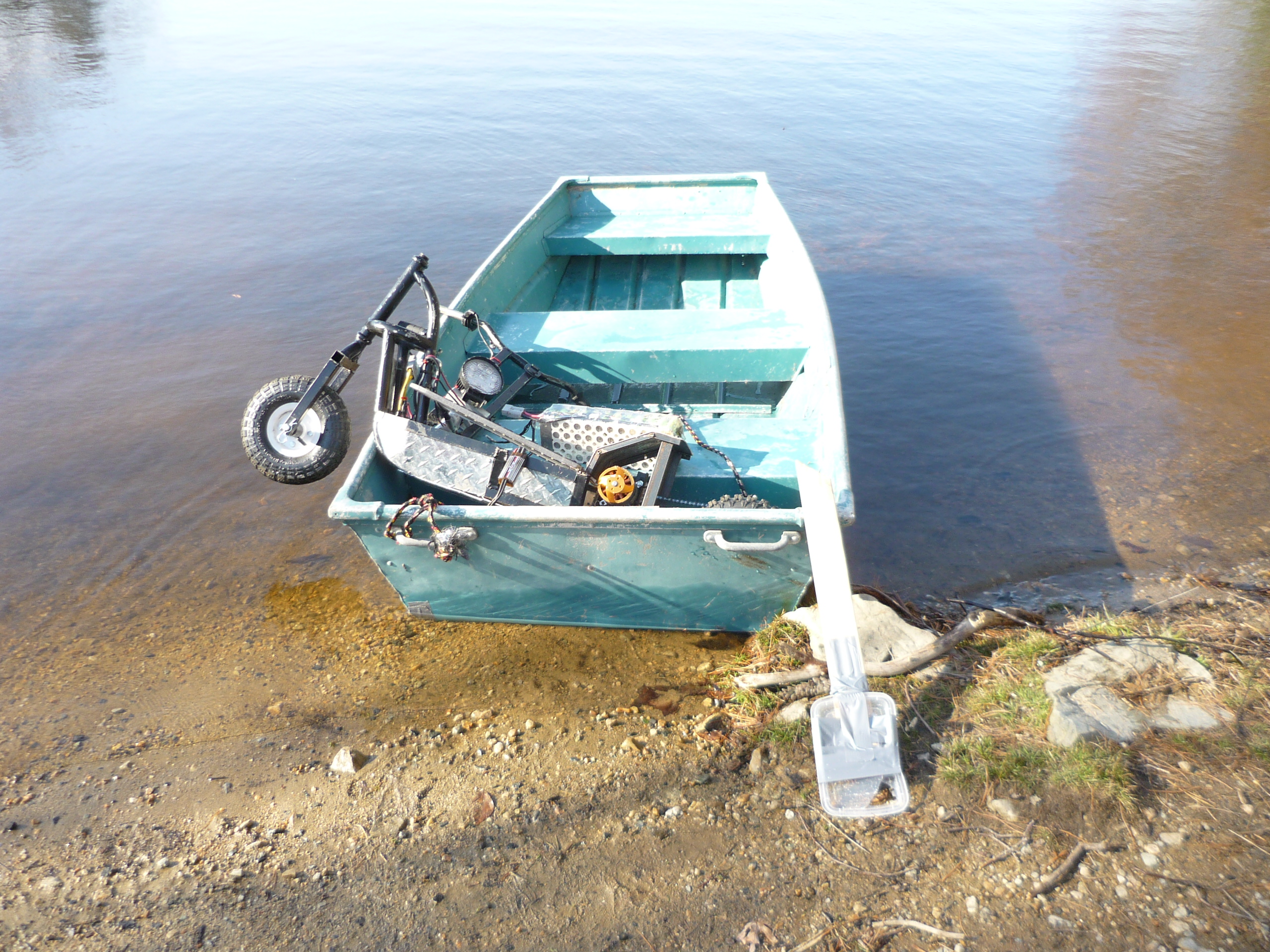
The
carrier
I was fortunate enough to come
across a wayward dinghy. I patched the small leak and it was deemed
water-worthy.
I quickly threw together a
'carrier' frame using square tubing and two
wheelchair wheels. The carrier frame was intended to mate with the
electric scooter / bicycle for the purposes of towing the boat around. |
 |
 |
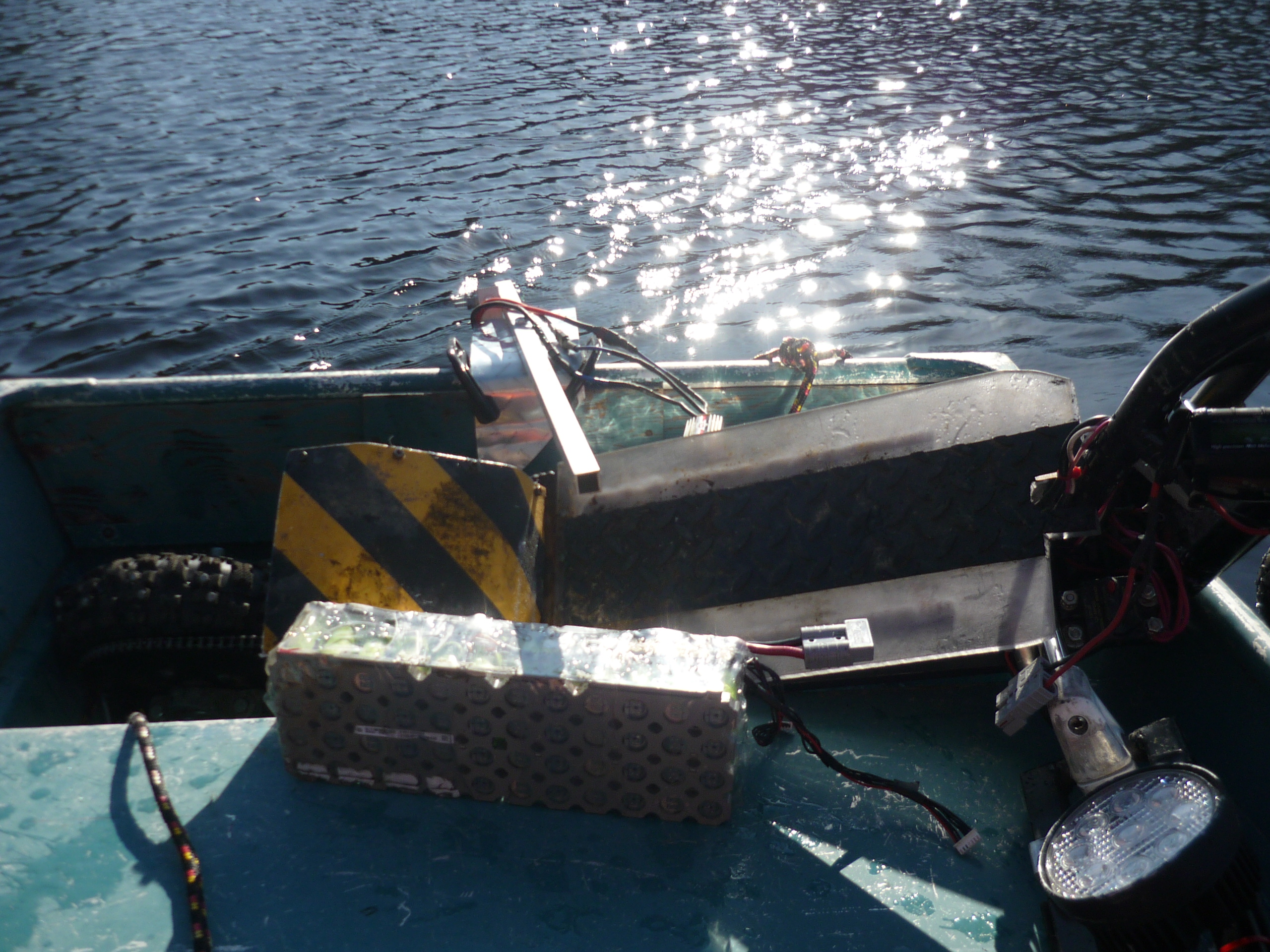
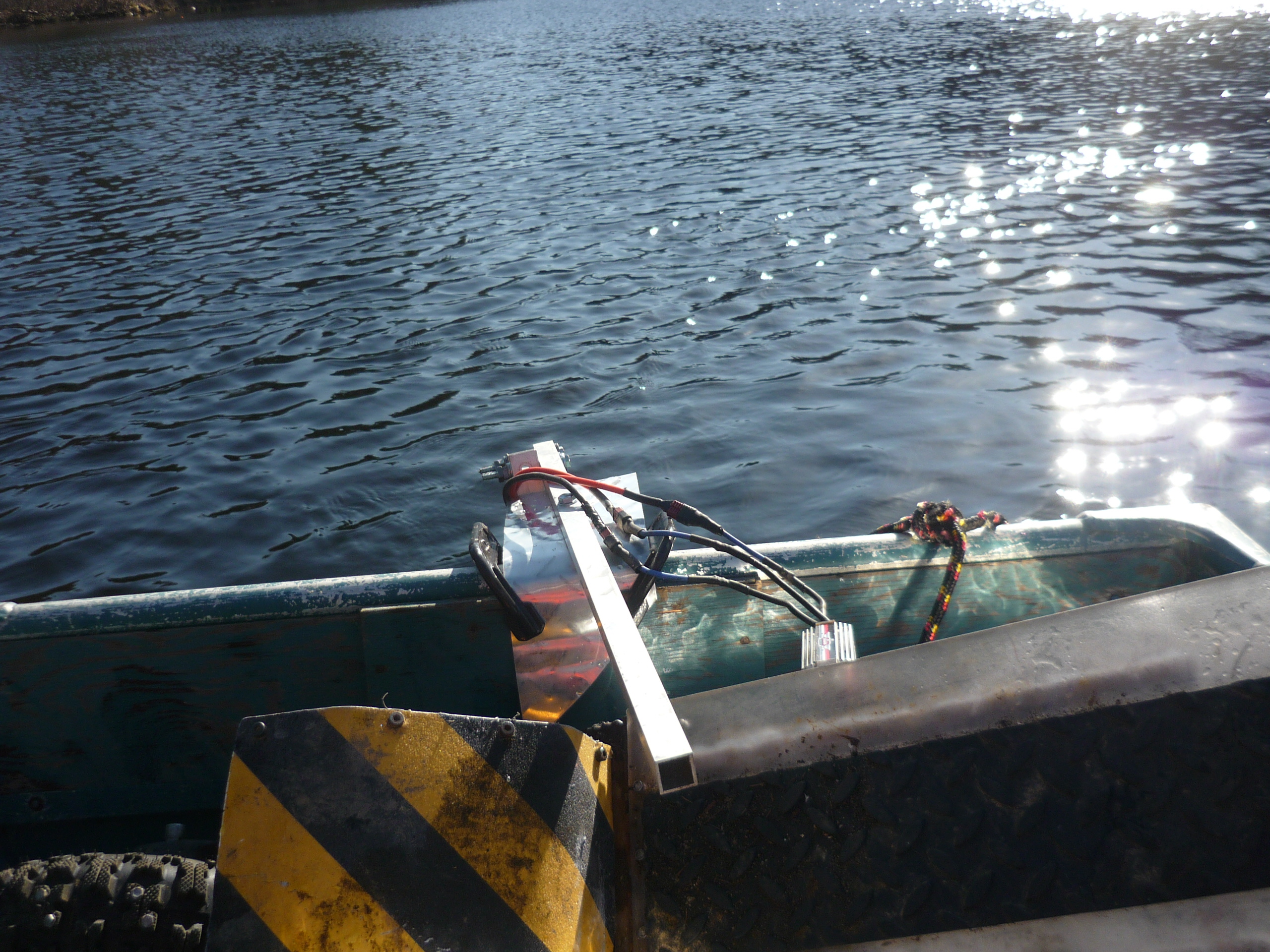
| After
the baseline test data was collected i wanted to translate linear force
into tangible speed. To do so in the simplest fashion, i took advantage
of a holiday weekend and retrofitted an aluminum dinghy for the purpose
of speed-testing. A quick pivot arm was fashioned from some spare
aluminum square tubing and clamped onto the back of the boat. |
 |
 |
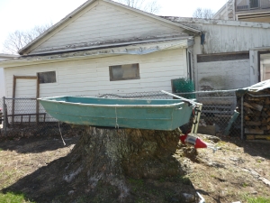
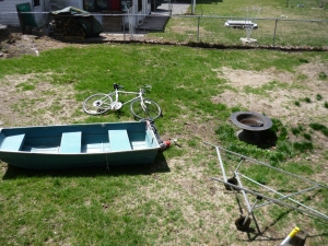
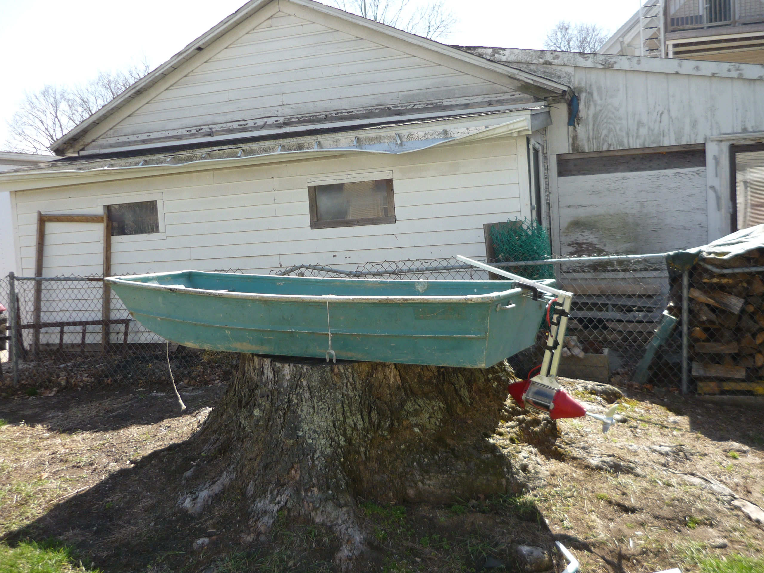
Here
is the setup
Ingredients:
Boat, thruster, crazy aluminum frame carrier and bike. To test the
setup, as the thruster would be below boat level, I lifted the whole
contraption up onto a nearby, very large treestump. As shown (far
right) the clamp-mechanism was not very structural, however, as this
test was for a rough estimate, it was sufficient for testing. Note the
boat itself has much more surface contact area with the water than the
canoe would, so the speed observed on water was a very conservative
estimate of canoe speed. |
 |
|
The
RAMP
after
constructing the boat carrier, I looked around and found a hidden boat
ramp entrance. No need for the fancy carrier after all! What
a
beautiful day! |
 |
 |
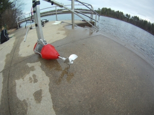
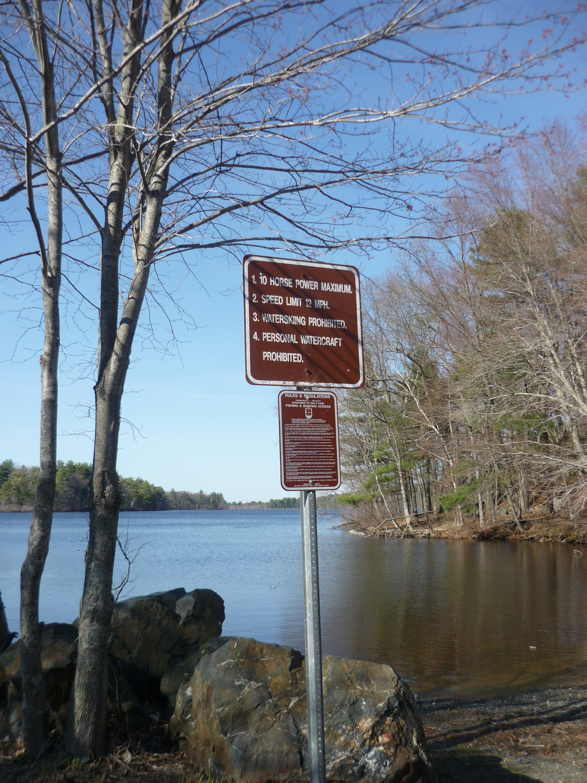
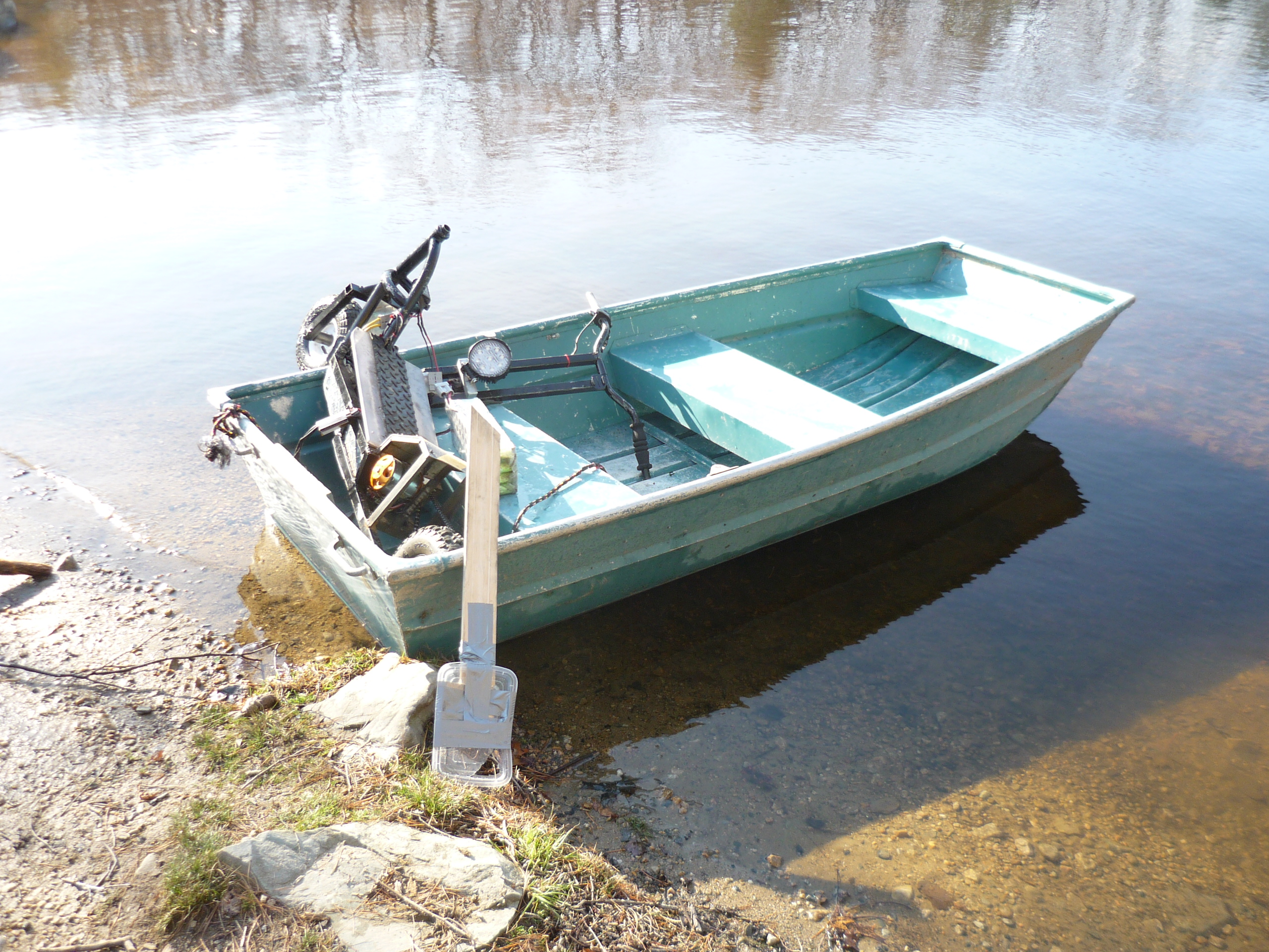
Setup
The
boat ramp listed rules for the resoviour, the <10hp rule was the
only one i was really interested in, and as i was controller limited to
~4kw, I was in the clear. As this was an impromptu test, the scooter
itself was used as the testbed for the boat. |
 |
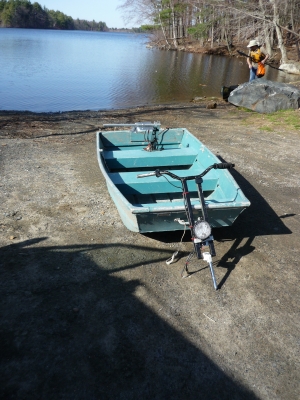 |
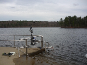
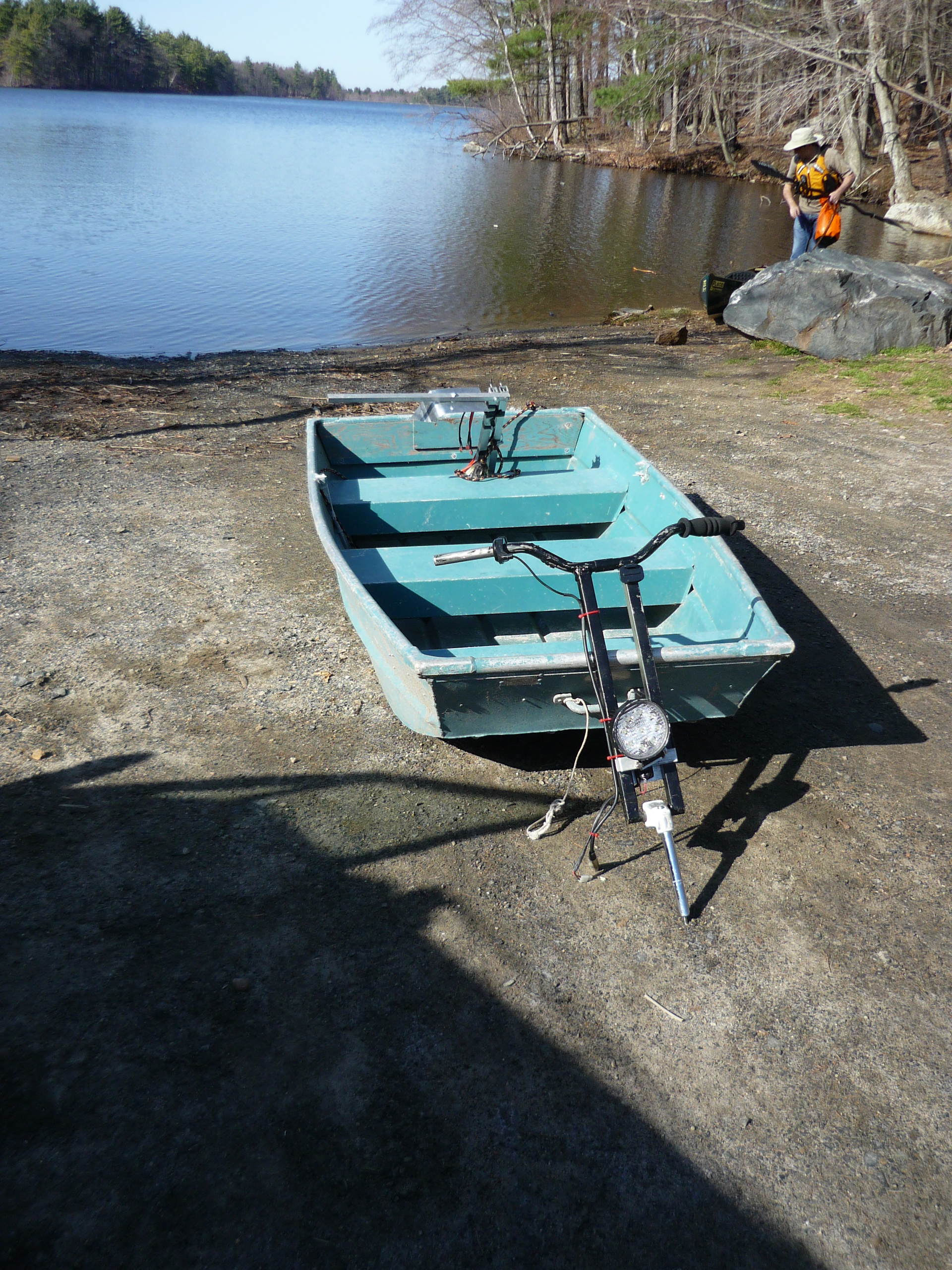
The
whole thing pre-launch
The
setup looked pretty ridiculous, but as most testbeds, it was intended
to serve a purpose: Test thruster performance and determine any issues
/ bugs that pop up. This purpose did not include looking fabulous. Then
again, its in the eye of the beholder. |
 |
 |
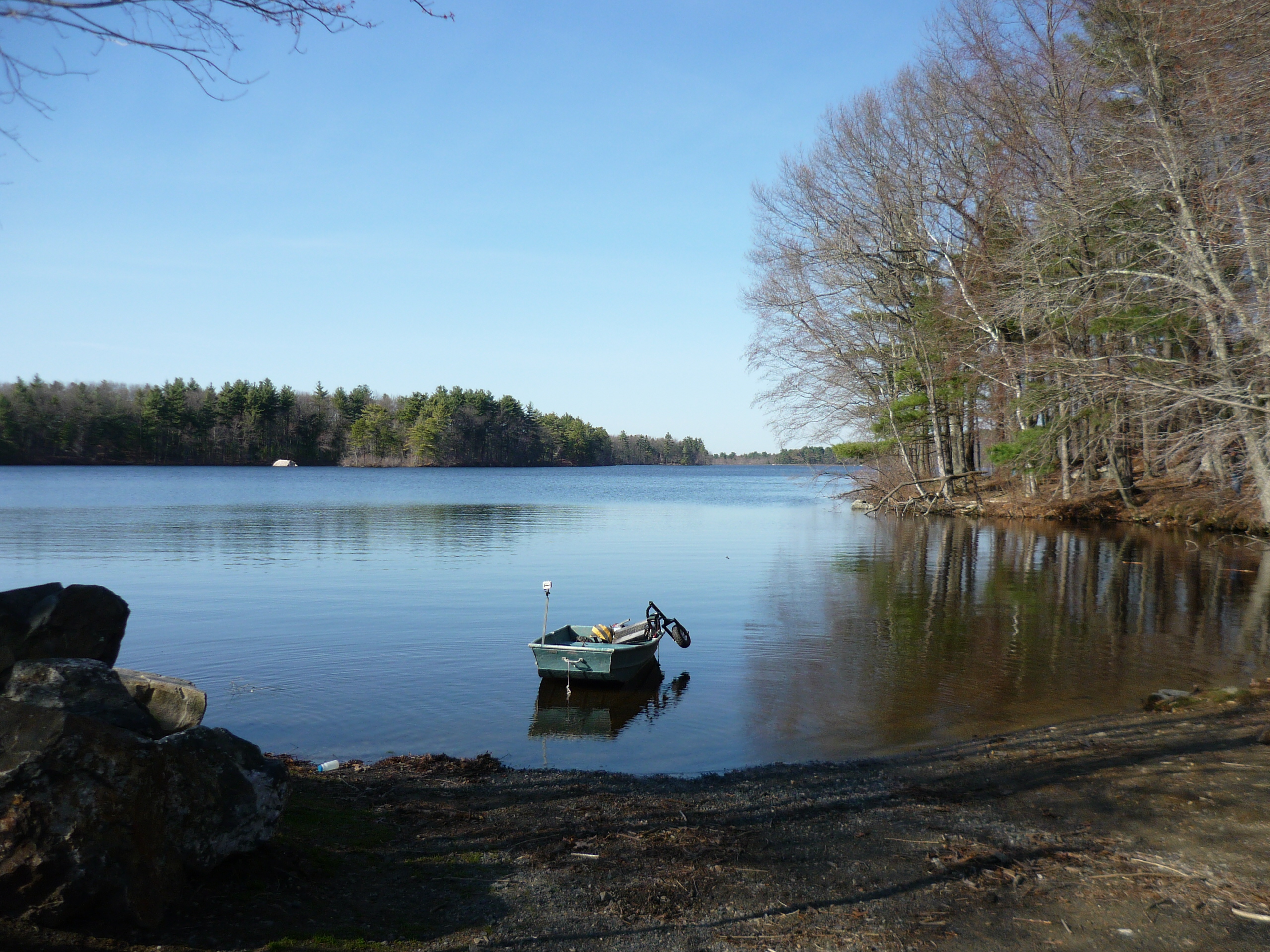
LAUNCH
After
wading out a bit, i fired up the thruster (twisting the scooters
throttle lever) . It produced an enormous amount of torque the front
lifted and I zipped off at what I can only assume was roughly ~8-12
mph. After approximately 1 minute of runtime, the controller, a turnigy
140A brushless ESC, crackled and exploded. A PLUME of magic-smoke flew
all over the lake. I was stuck in the water unfortunately. I used a
small oar, made from a food container and a plank to row back.
|
 |
 |
Lessons
learned
*
The motor mount has significantly more thrust than i anticipated, and
twisted the steering driver bracket. Some of this thrust is directed
into rotating the thruster about the mounting axis.
* The motor controller can not handle full power for extended periods
of time.
* Invest in a proper paddle, or make one, and tie it to the craft.
* Build a proper test apparatus, prevent risking the scooter from water
immersion.
* START THE GOPRO CAMERA BEFORE LAUNCH. Unfortunately I do not have
footage of the motor controller failure. |
 |
 |
Concluding
Remarks:
Boats have a lot of drag, this was a super-conservative estimate at the
speed of the final craft. Testing on water is fairly trecharous,
there's quite a bit of excitement to go out on the water and just head
off into the distance. Unfortunately in this excited state, I neglected
to start recording video using the gopro camera mounted to the craft.
The motor mount for dynamic testing was found to be too
flexible
for proper testing, as it would flex based on motor power output.
Finally, the cowling shield for the rear portion of the thruster
required epoxy reinforcement as portions of the plastic cracked under
dynamic testing. Finally, have a backup plan! Having an oar is
very useful for the case where the motor controller fails, catches on
fire, or both. I had brought along a very, very last minute oar and,
while it worked, it was fairly inefficient.
If you
have questions or comments, ask below or send over an
email.
(be
careful, the water is cold this time of year. Wear a pfd and stay warm!)
Dane.Kouttron
Rensselaer Polytechnic Institute
Electrical & Electrical Power
631.978.1650


