Dane.Kouttron
[5.25.14] Submersible Thruster: 3 Phase Liquid Cooled Propulsion
| What?
This project documents the design and developmental testing of a high-power, sealed, submersible thruster for an upcoming hydro-project. The end goal of this project is to have an easily reproducible, high-power submersible assembly that allows for high speed maneuvering in aquatic environments. This design uses off-the-shelf parts to allow for ease of duplication. Design files are open and available for download. |
 |
 |
 |
| What? |
Demo Video | CAD | Assembly | Leak Testing | Bill Of Materials | Download | Conclusion | Image Directory |
Design Requirements
| What
is it that I actually want to accomplish here? |
The goal here is to design a
submersible motor assembly that is able to accomplish the following: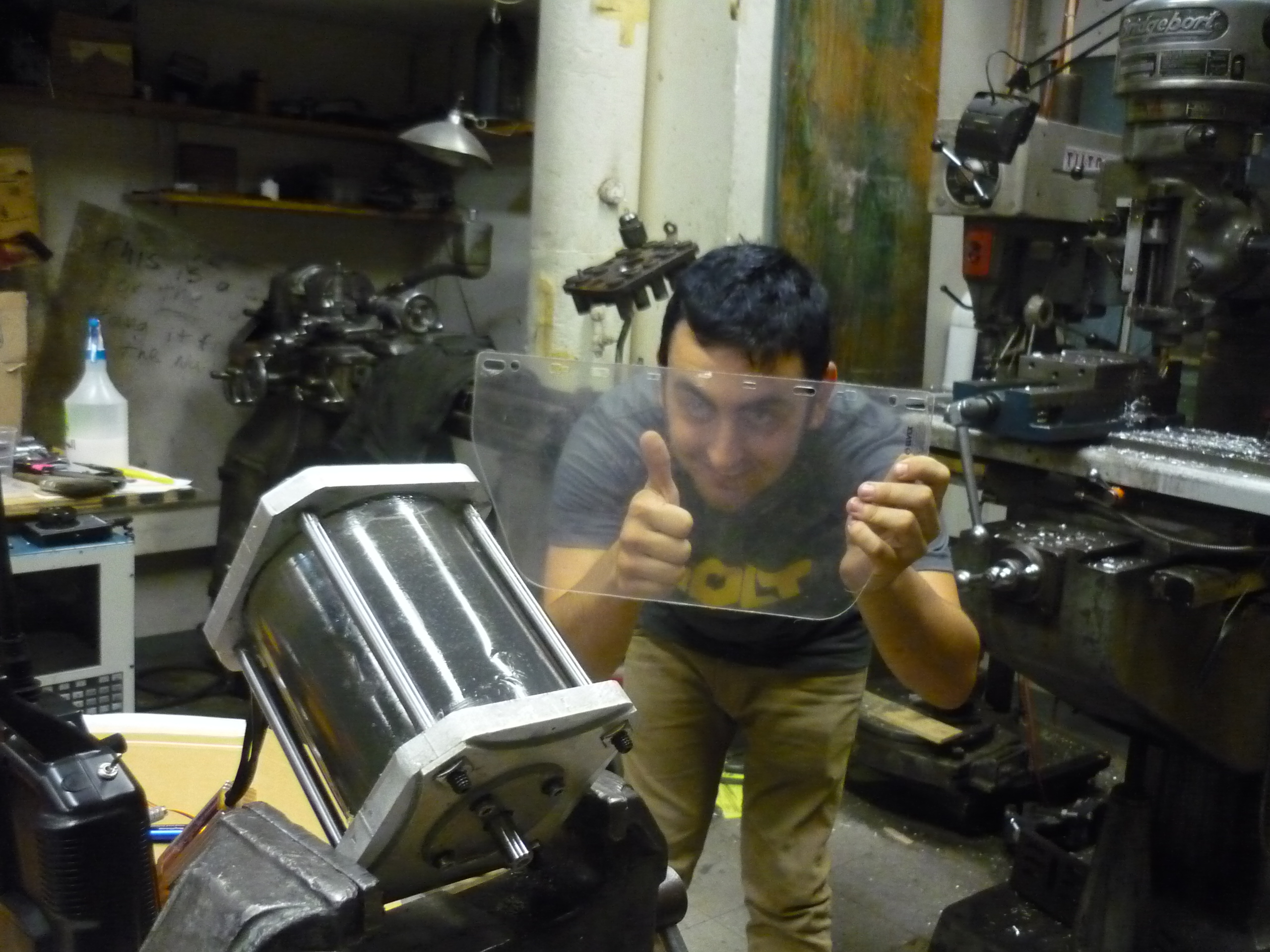
|
| Starting With A Basic Design | ||
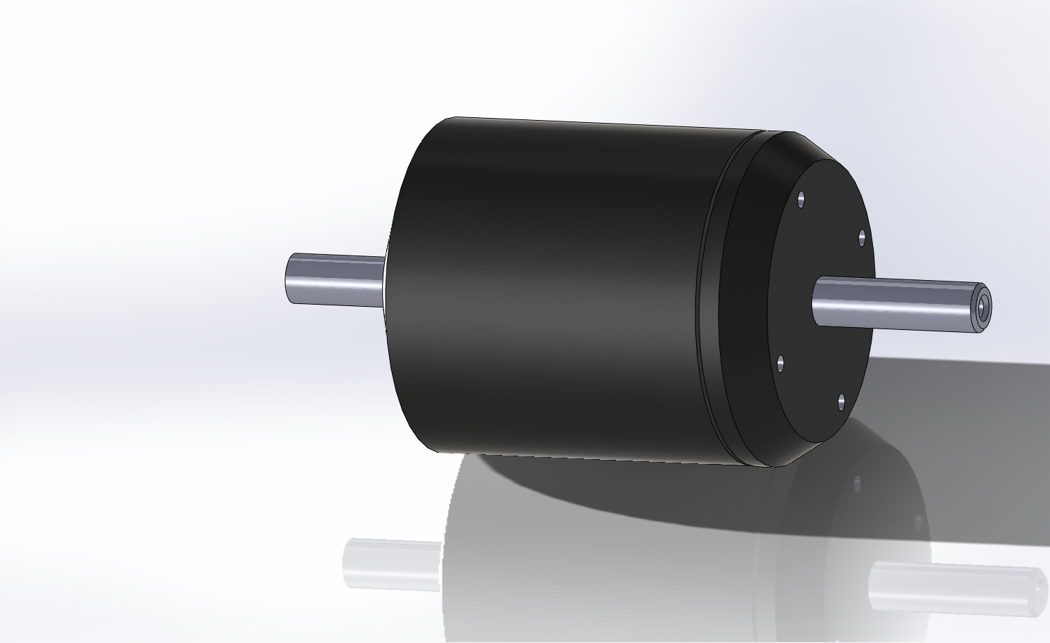
| I
started with some draft CAD models, based around the 'melon' sized
three
phase motor assembly. This required some attention to detail in the
modeling, to make
sure everything 'would just fit' together. As a note, the C80-100/180 series
outrunner motors use M5
screws, not M6.
I used this motor on the electric scooter/snowscooter and it was awesome, loads more power than necessary. Also available here: [link] |
 |
 |
| Initial
sealed motor and propeller designs Having no prior experience in hydro-design, I took an iterative approach, worked with hydro-minded colleagues and incrementally tackled design challenges. The design morphed from an impossibly large fan-turbo-prop with shroud, to a more torpedo-shaped design with a cowling. This design change occurred after reading David Gerr's Propeller handbook [amazon] [check your local library]. |
 |
 |
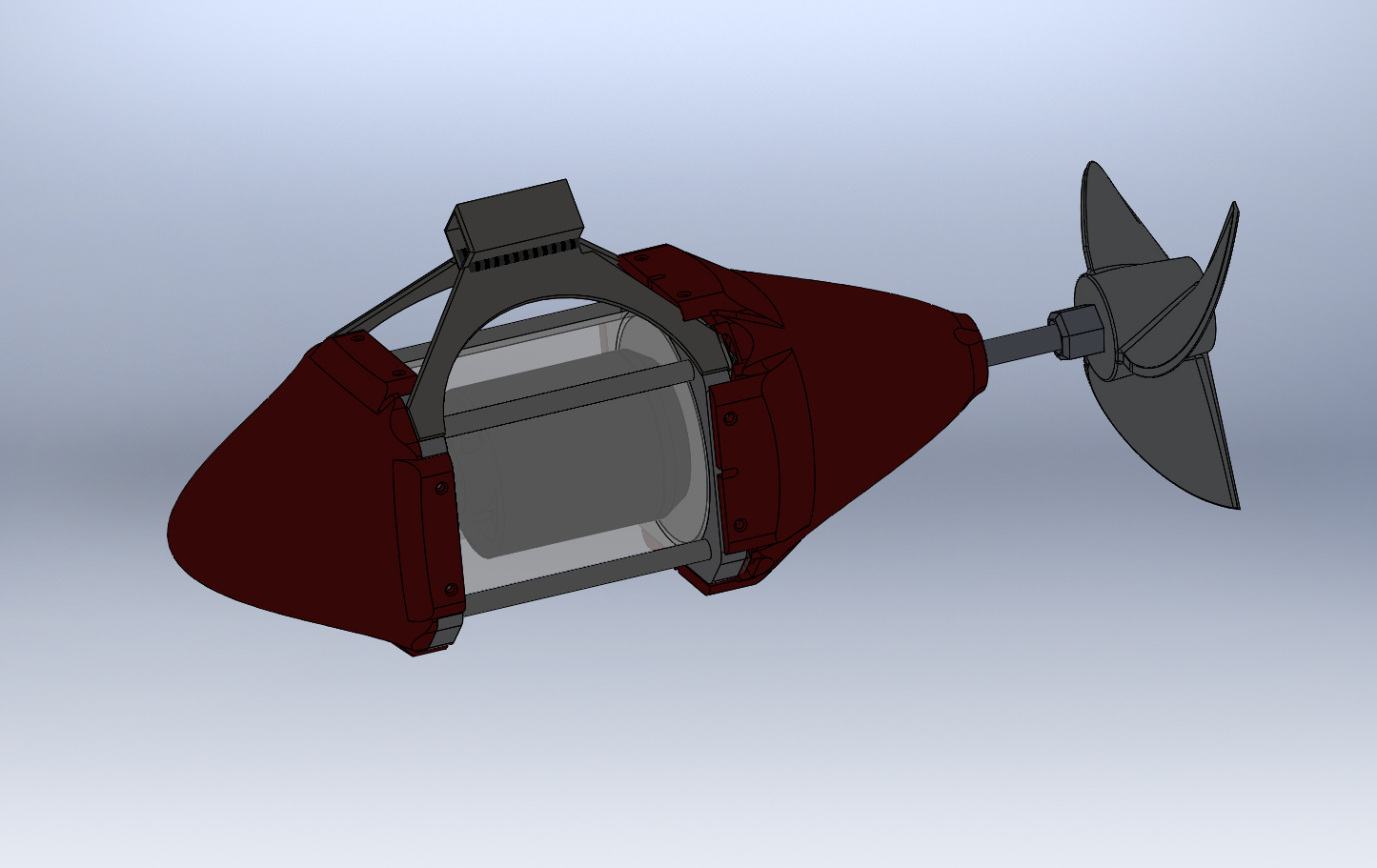
| Design improvements Initially I had opted for a stumpier design, where the thruster and prop lived almost on top of each other. Unfortunately this would result in a pile of cavitation and restricted flow to the prop. Moving the prop away from the 'not quite hydro dynamic' flat face of the thruster, seemed to allow a less turbulent path to the prop. |
 |
 |
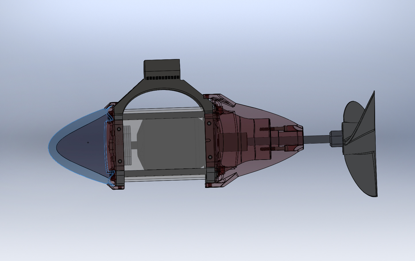
| Getting
closer... After iterating the cad model, and taking advantage of large 3d printed parts to add in a more hydrodynamic water displacement mechanism, the thruster began to come together. During the design phase, I contacted a comrade with experience at Cornell's AUV team [link]. Shaft seals, dealing with bulkhead passthroughs and the like were discussed. Opting for a clear can stayed in place mostly due to my stubbornness, although it could definatley do with some inner leds. |
 |
 |
| Assembling The First Thruster | ||
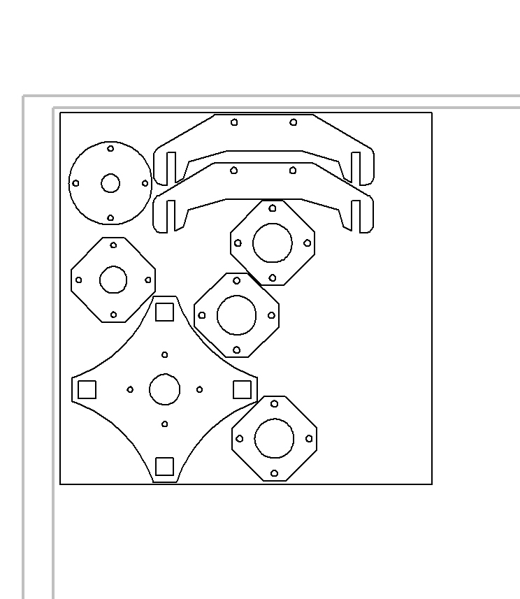
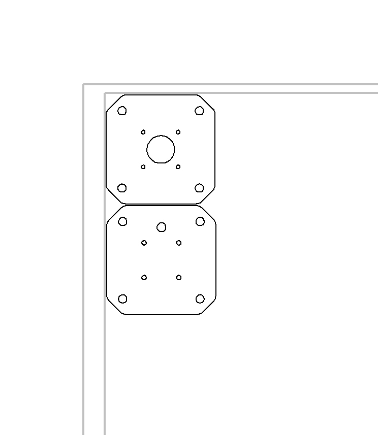
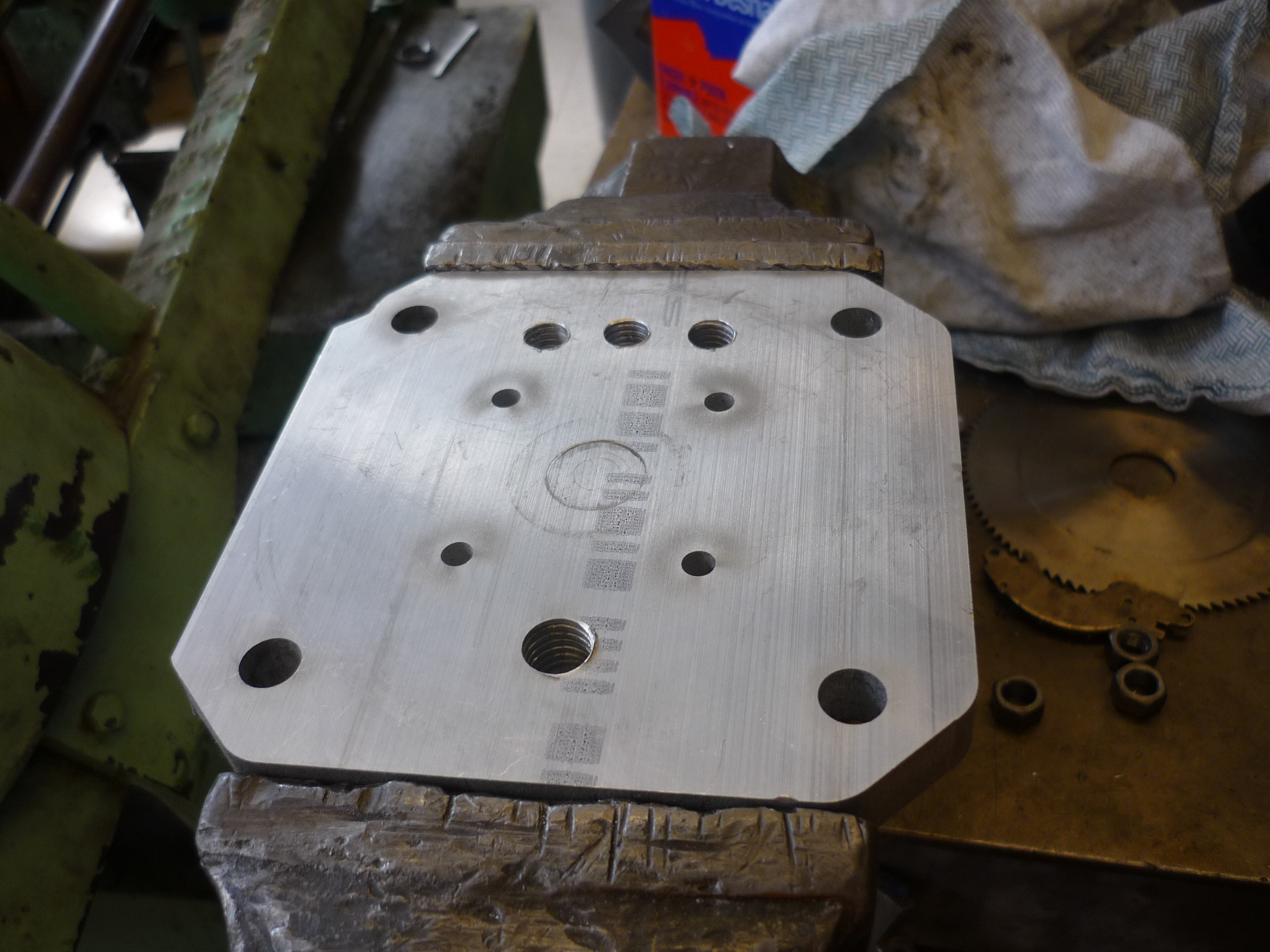
| Laying
Out for Waterjetting After the design was complete in solidworks, i made a solidworks drawing. The first image (close right) shows all the 1/8" thick components fit into a 1' square aluminum 6061 plate. The second image (far right) shows the front and back plate for the thruster. Note that on the 1/8" thick plate, two side-clamps for a potential shroud were cut, in case a shrouding was necessary later on in the project. |
 |
 |
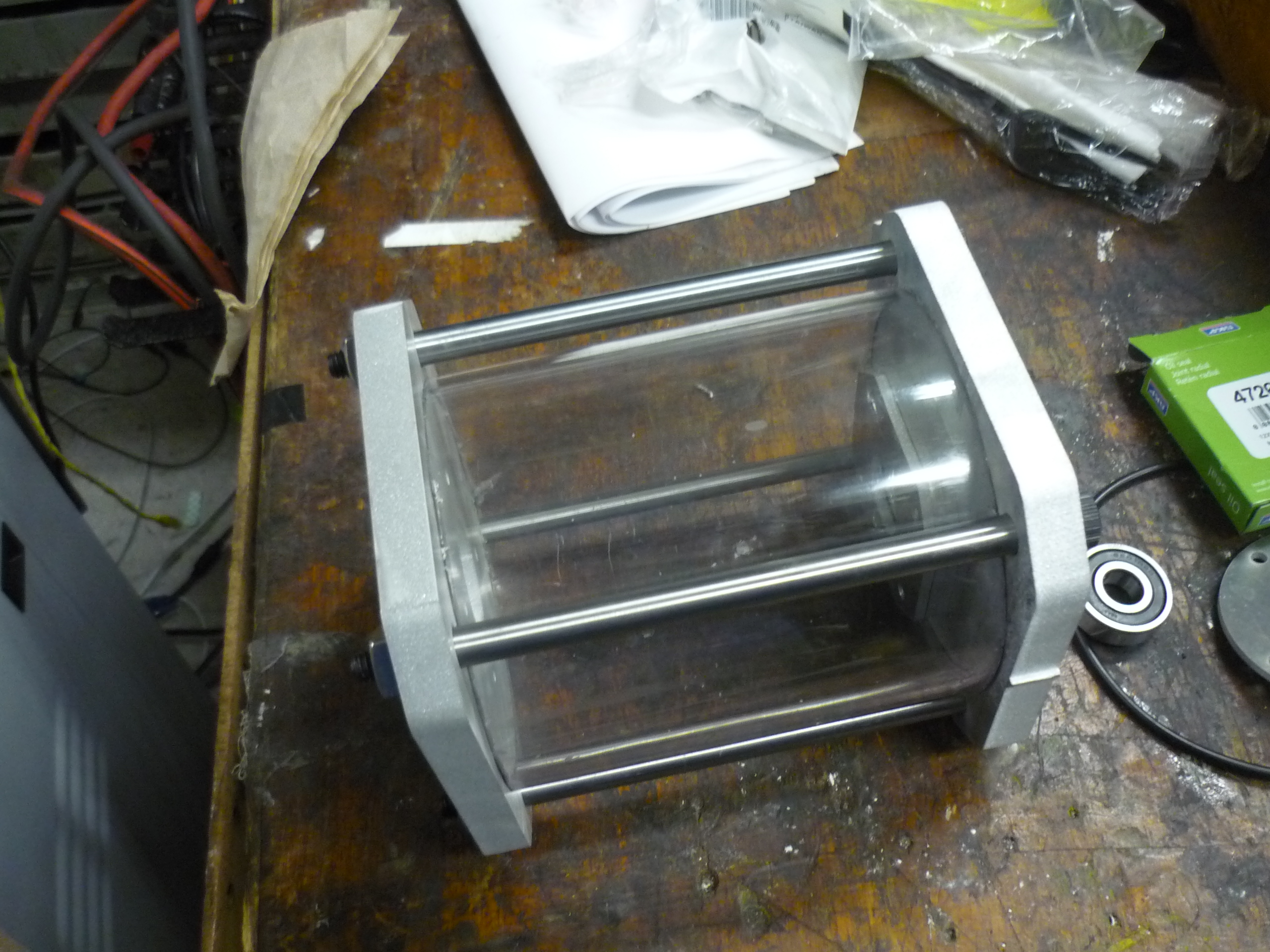
| WATERJETING! Unfortunately the MIT hobbyshop was down for the summer, fortunately a comrade with some excellent connections, was kind enough to make the cuts. The aluminum components are either from 0.5" thick 1' square sheet / 0.25" thick stock. I quickly setup a mock up of a hollow assembly. Everything fit together! |
 |
 |
| HAVE
I MENTIONED THAT WATERJETTING IS EXCELLENT? There's something to be said for spending a while in the design-cad-redesign, caliper-heavy stage of development. I was fortunate enough for everything to fit together fairly well. The excellent part is this same file can be used to make a nearly identical assembly later down the line. The outer portion of the frame (last 1/8" plate) acts as a lock-nut holster for the four main bolts. Note these bolts were overkill and a half, realistically, a less-fancy bolt, or a hollow tapped tube with shorter bolts from either side would have worked as well. |
 |
 |
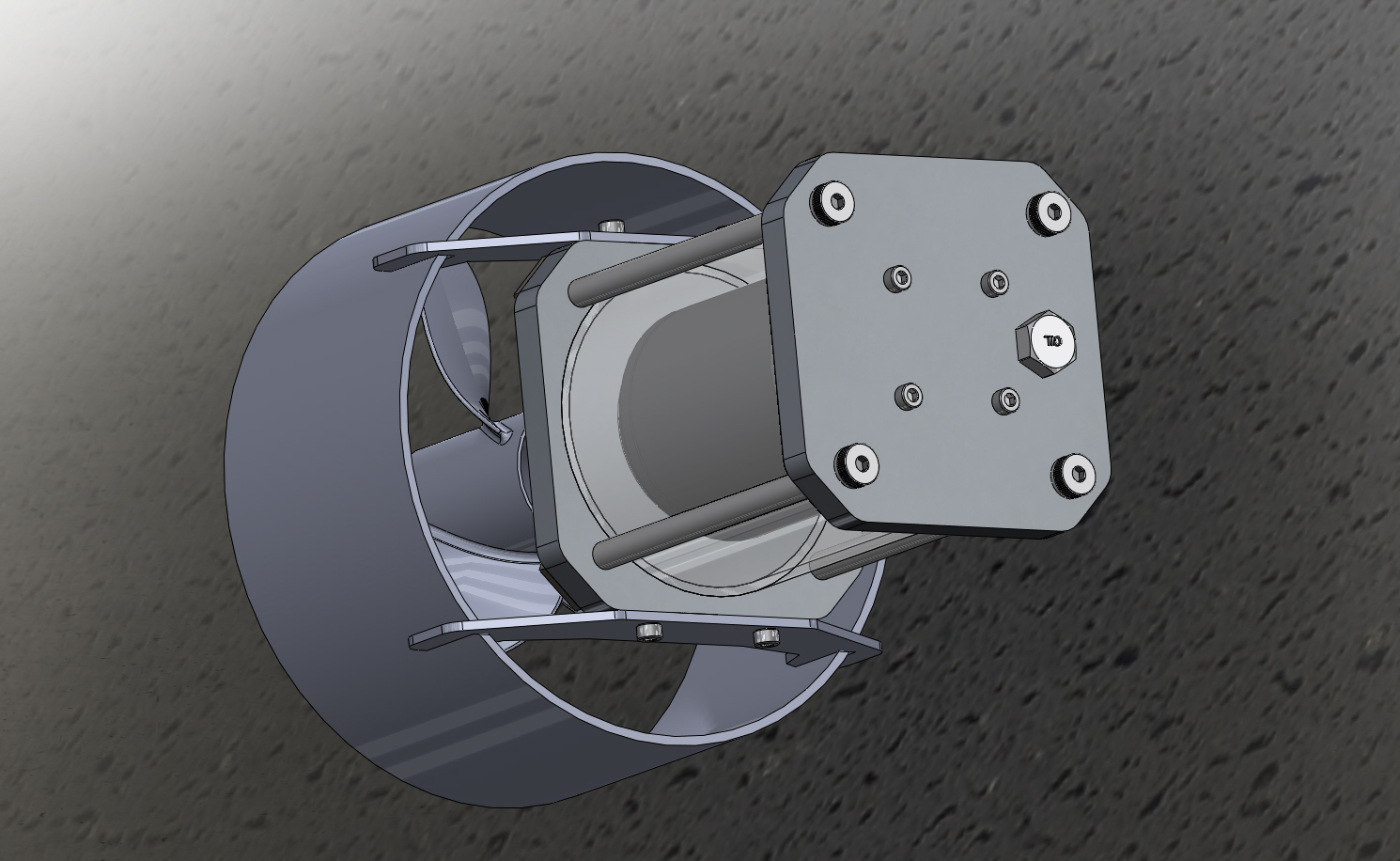
| Assembling Motor mounting, tapping, and gaskets | ||
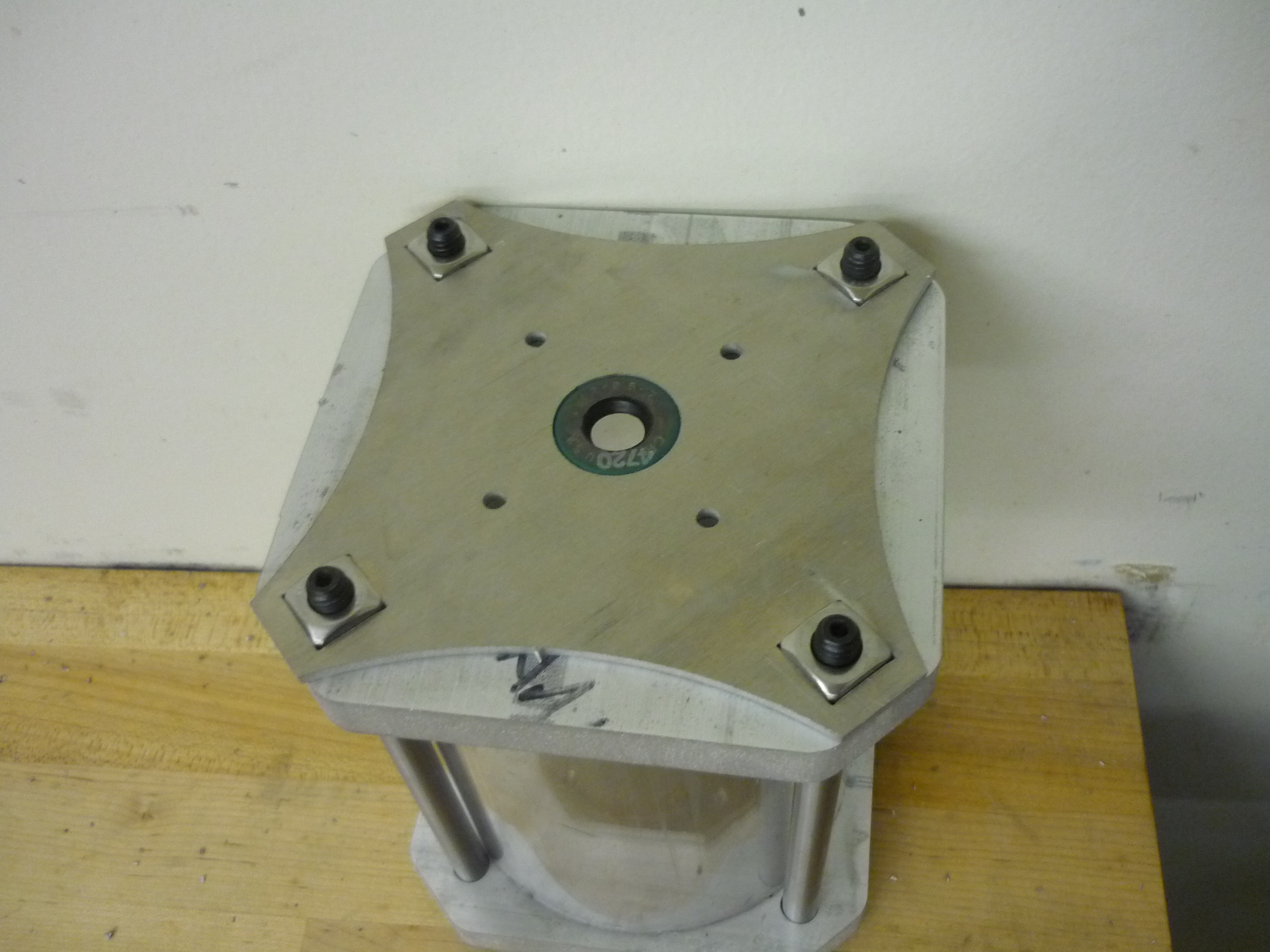
| Motor mounting and bearings Fortunately the motor mounting went smoothly, and the bolts threaded directly through the waterjet holes right into the motor assembly. I used the M5 bolts to verify the position of the motor and to make sure there were no unforeseen protrusions preventing it from mating with the base of the fixture. |
 |
 |
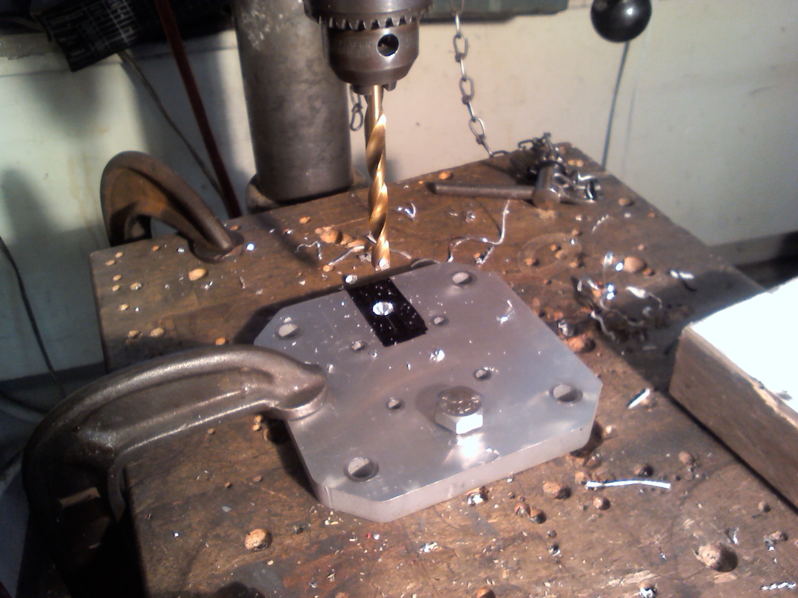
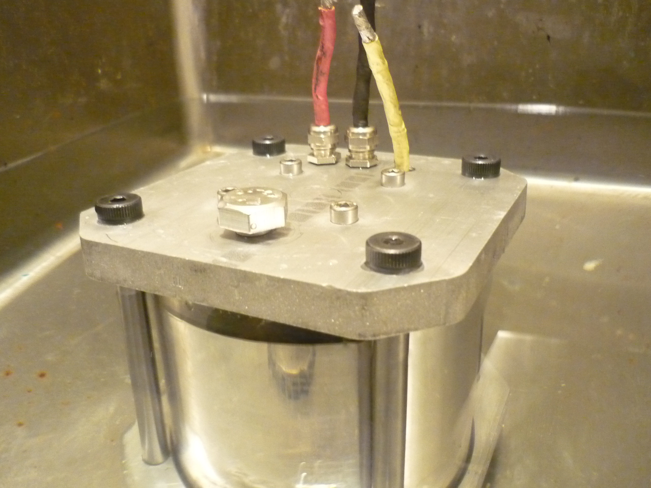
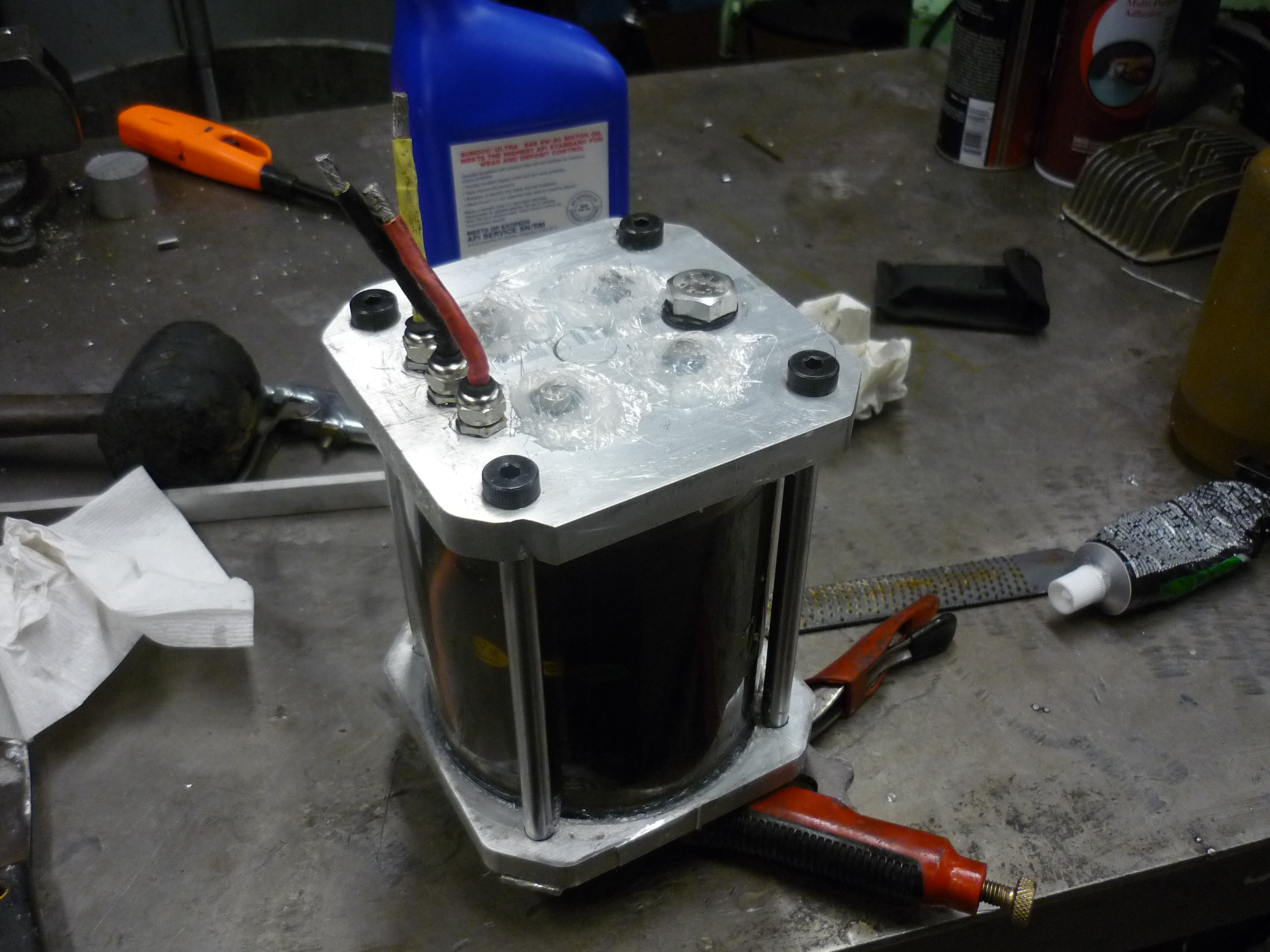
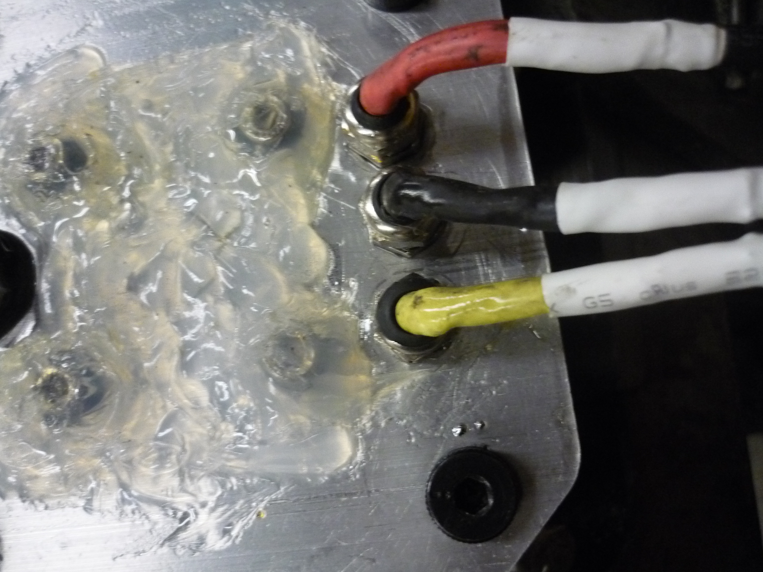
| Drilling the
3 phase feeds Initially I had the concept of running the three separate feeds out of the insulaive polycarbonate shell. After a quick mock-up, there was no apparent way to do this without introducing a significant probability of leaking. Instead I opted for mcmaster part: 8183K7. Using three separate mini M10 pass-throughs, I was able to feed the power out of the oil filled environment without any significant leaking. Note the wire gage from the motor was slightly larger than the maximum the part datasheet allowed, this may result in less tension on the wire than the part was designed for. |
 |
 |
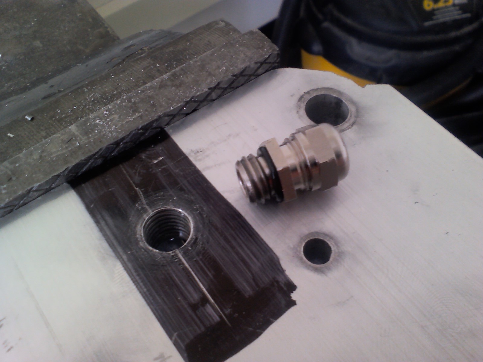
| Tapping
the 3 phase feeds I had to order a metric M10 Tap. Using a hand-tap I was able to get each of the three cable gromits installed without breaking a sweat. Tapping fluid is not only a great deodorant, it also works fantastically at tapping things in aluminum. The three cable gromits maintain a watertight seal for the three phase motor wire. |
 |
 |
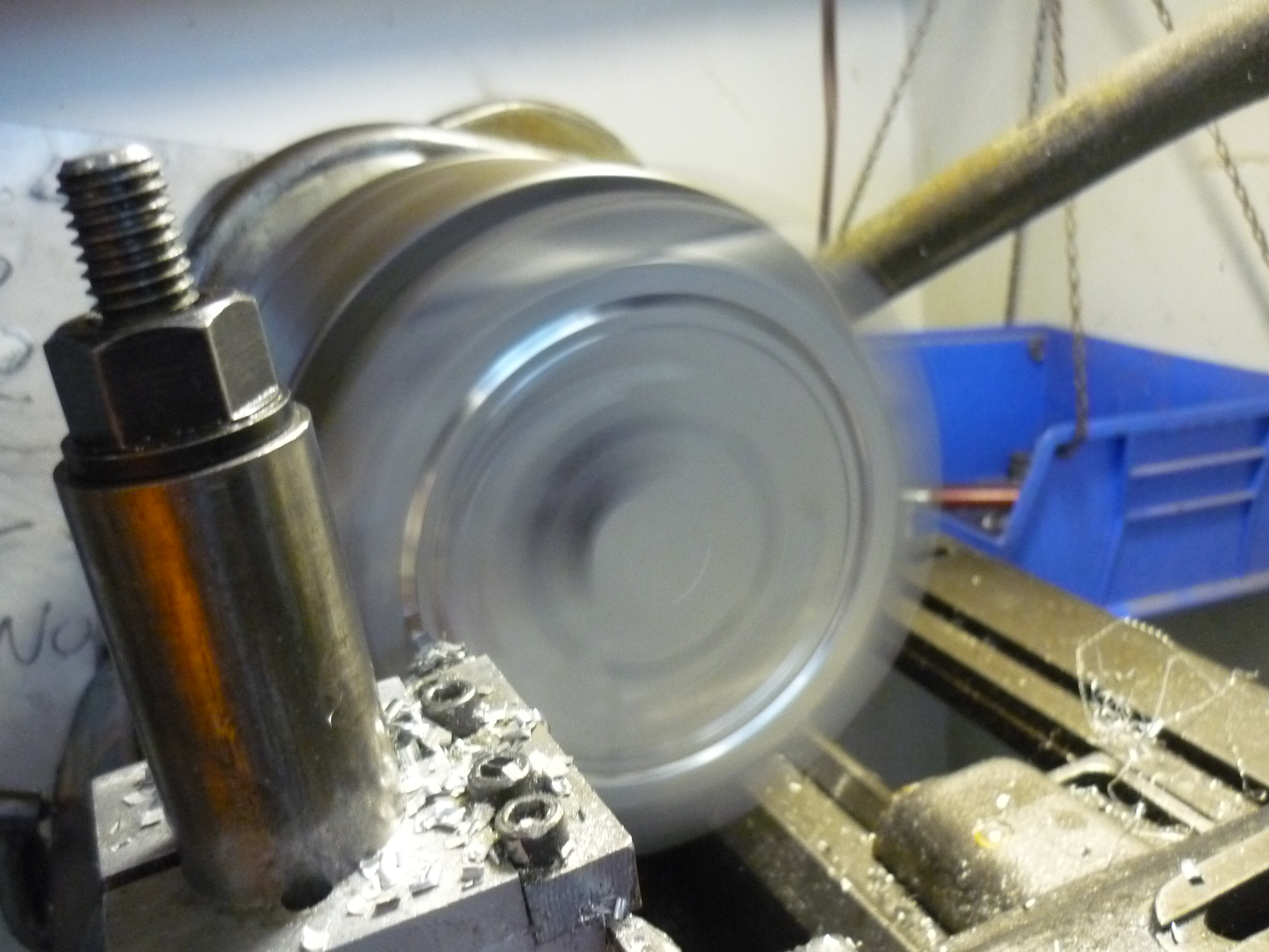
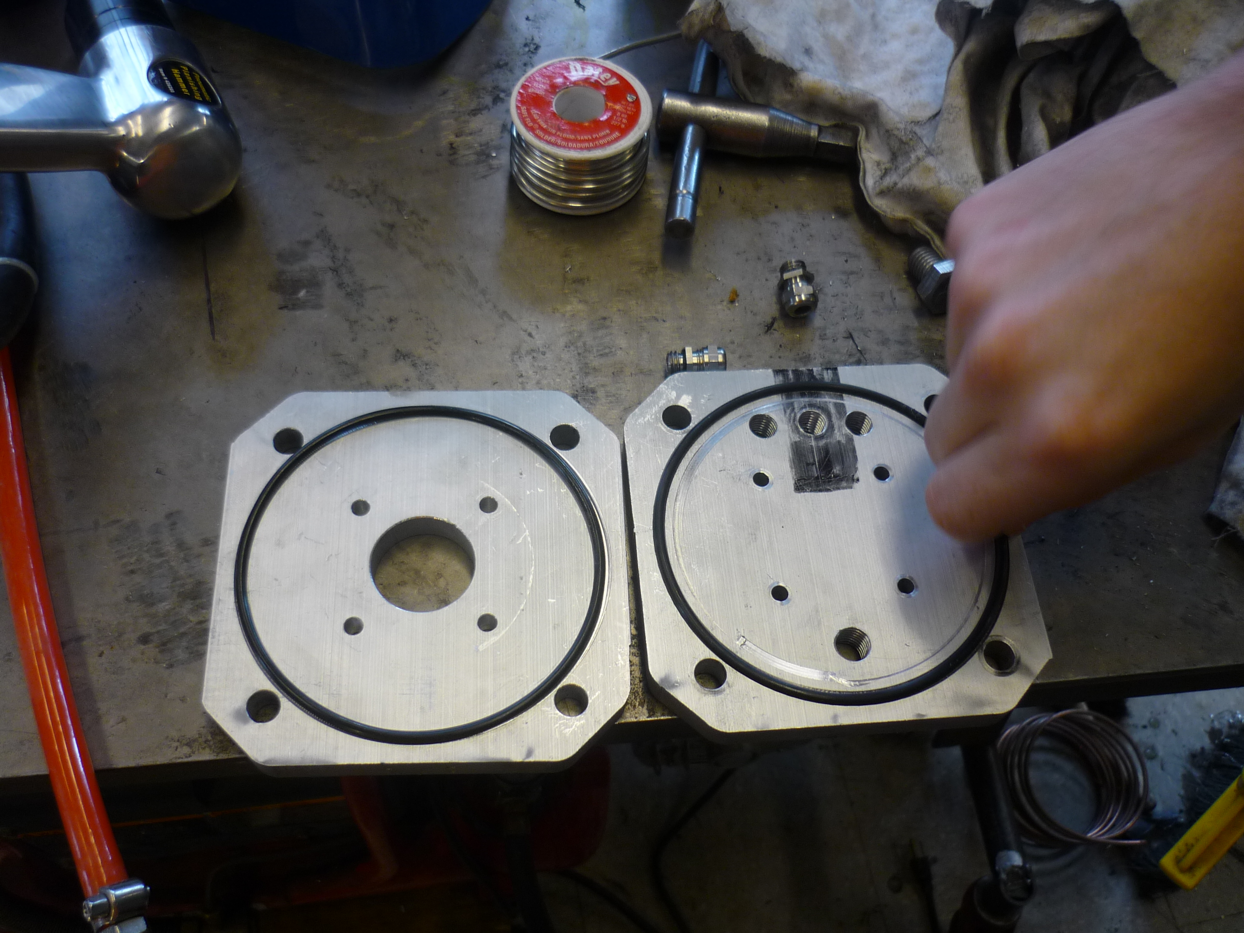
| Square
Jaw lathe chuck & an o-ring groove There's something magical about centering things in a 4-jaw chuck. The easiest mechanism i had found was to use the tool as a scribe, rotate the part slowly by hand (while the machine is de-energized), and measure the difference between the edges and the closest tangential point on the circle. Too much and it needed moving. After 30 minutes of jousting the part back and forth the placement was set. Time to CUT! |
 |
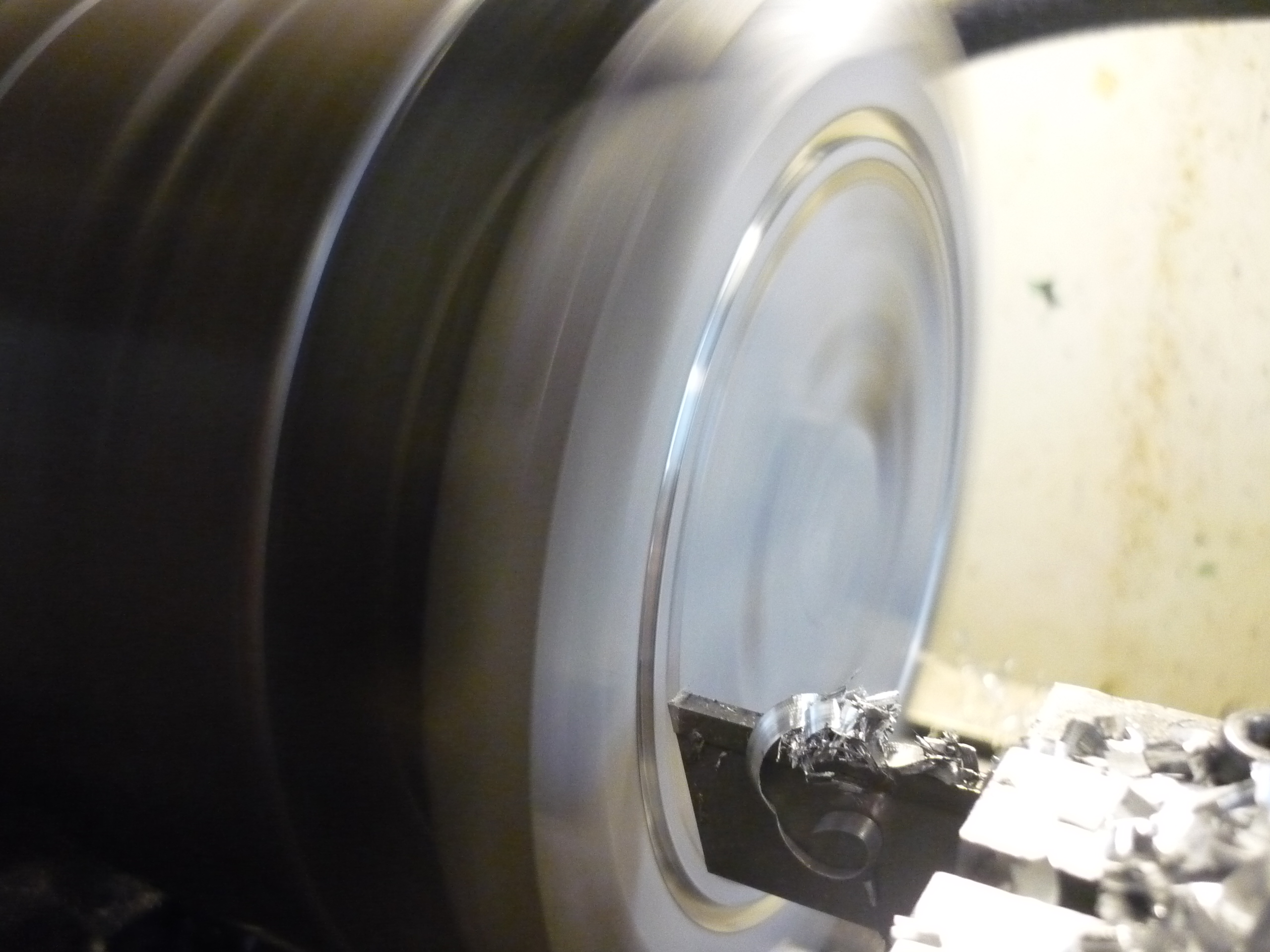 |
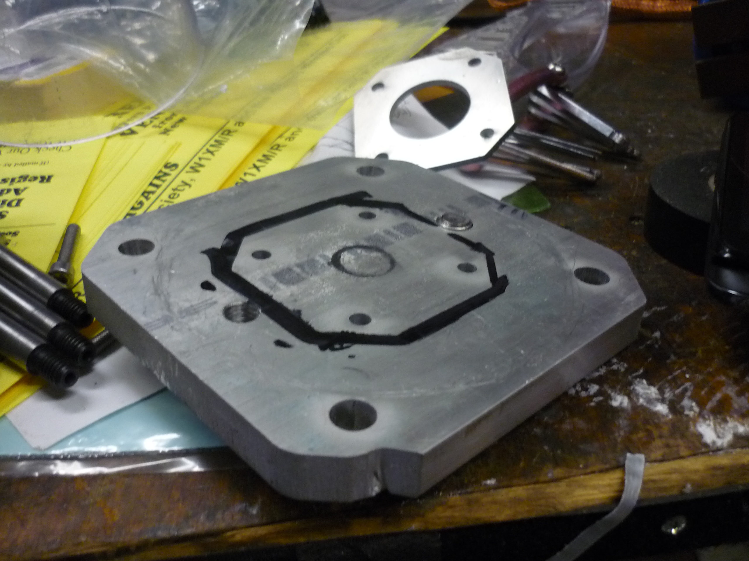
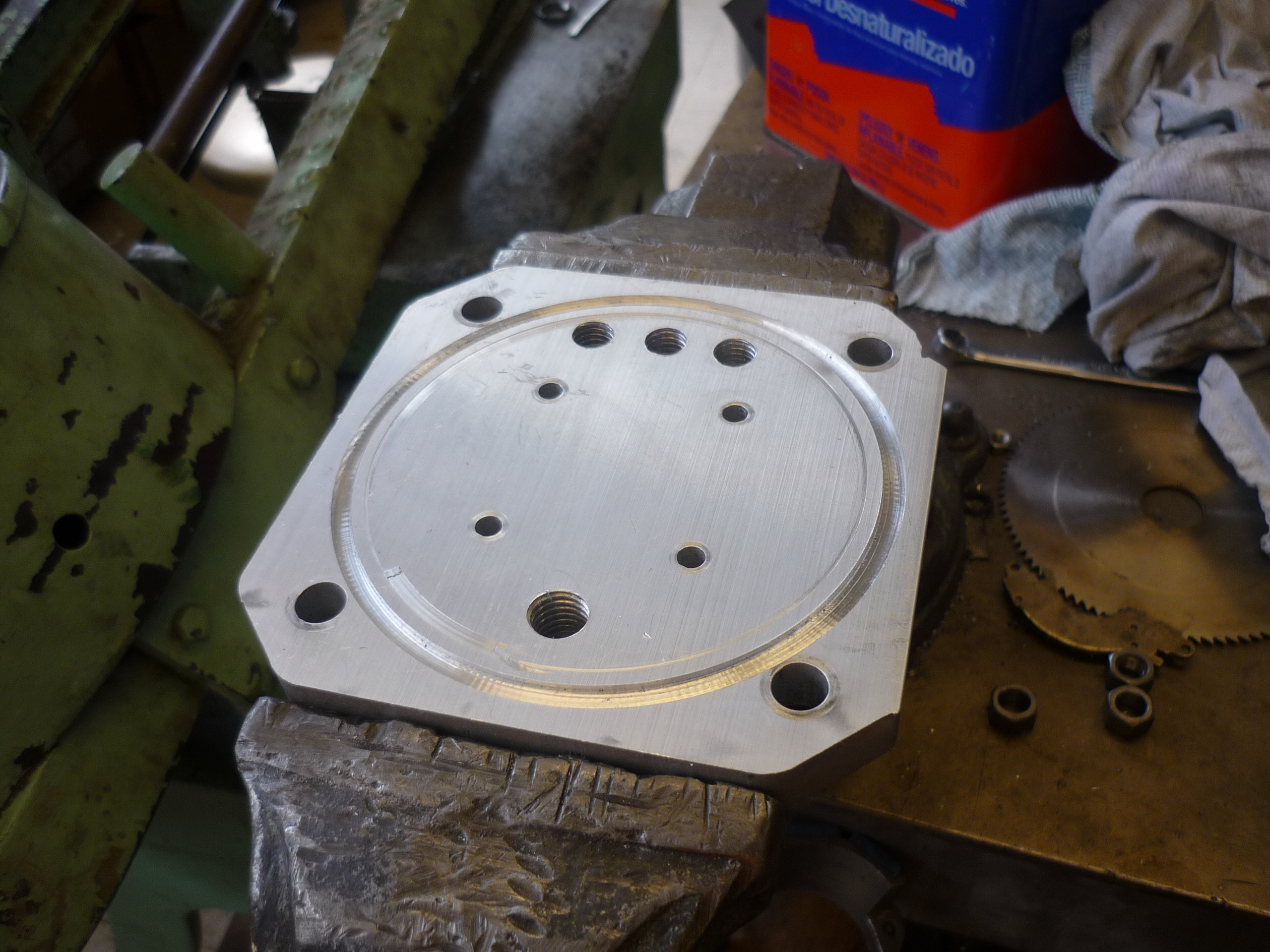
| Before
and After Using the 4-jaw chuck i was able to get a fairly centered circular o-ring path, shown right. The groove was a bit of cut-and-check for width and thickness, but after a half hour of toying I was able to get the right dimension. |
 |
 |
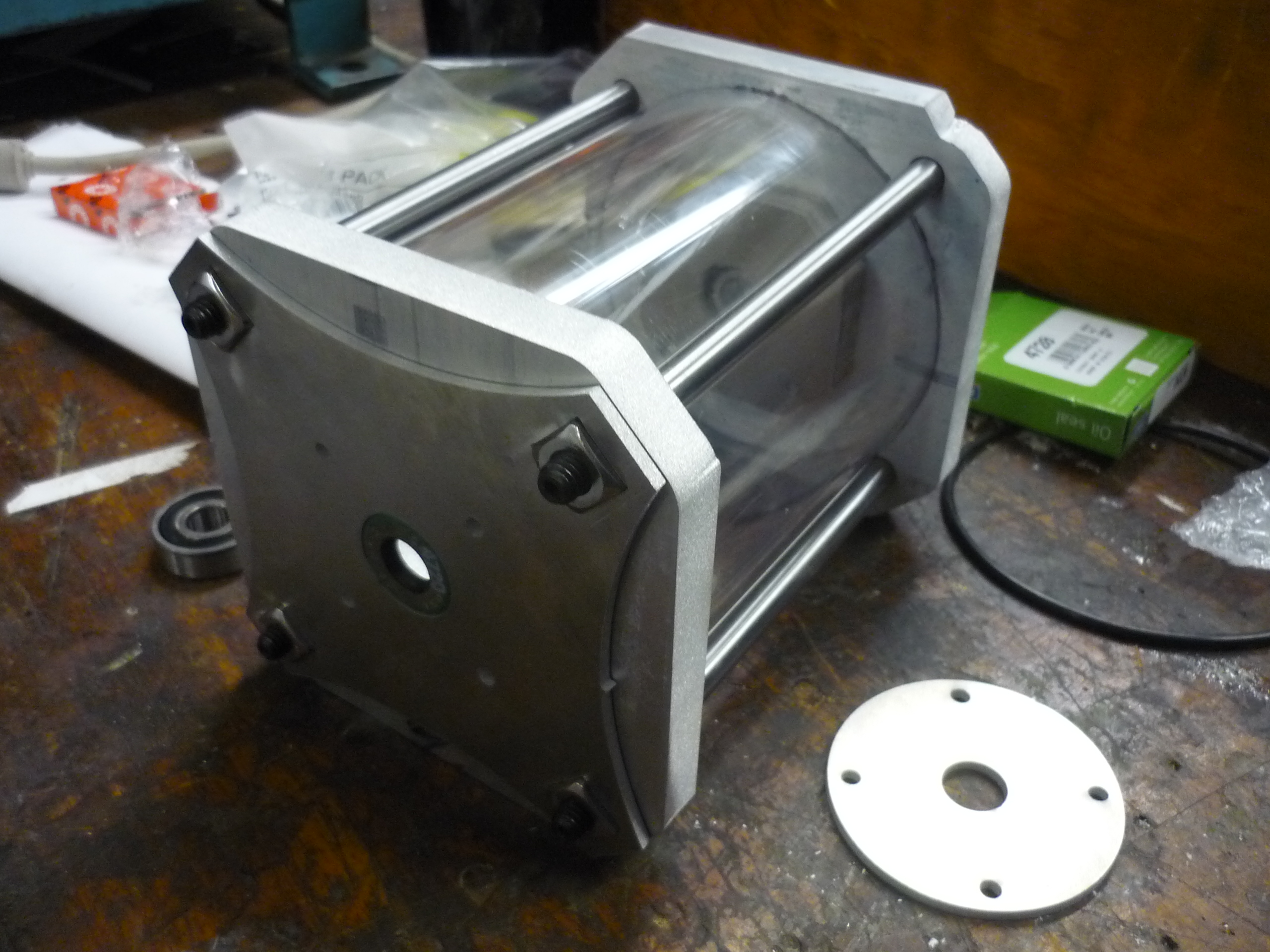
| O-rings
are tricky After milling the groove for the two o-rings, a bit of trial and error was required, due to some rough depth-gaging using lathe back-end of a caliper. After getting the right depth, the polycarb housing was sandwiched between the two gasketed plates. Having the o-rings fit snugly inside the grooves was a bit rewarding, as, any error would require re-cutting new faceplates. |
 |
 |
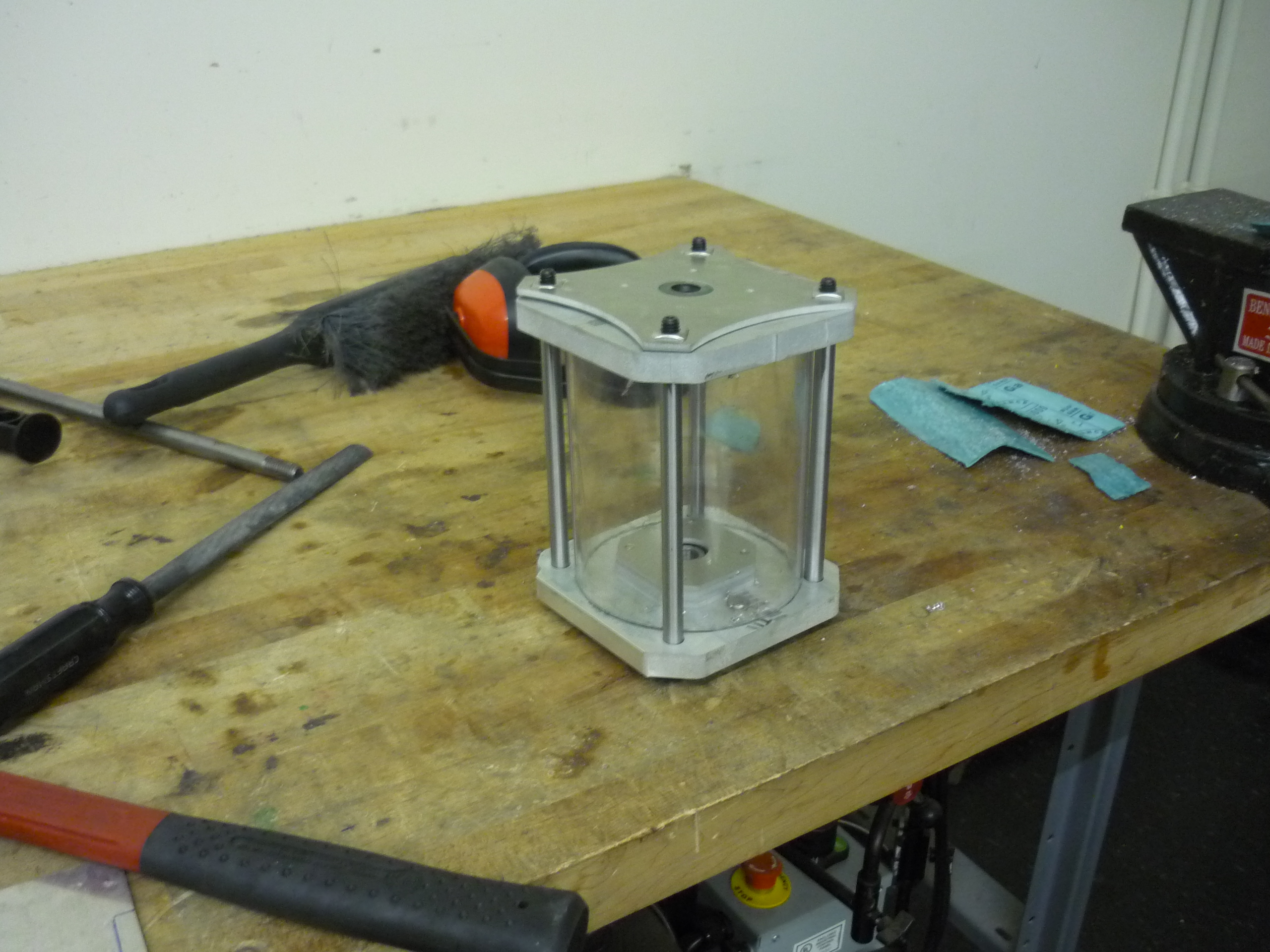
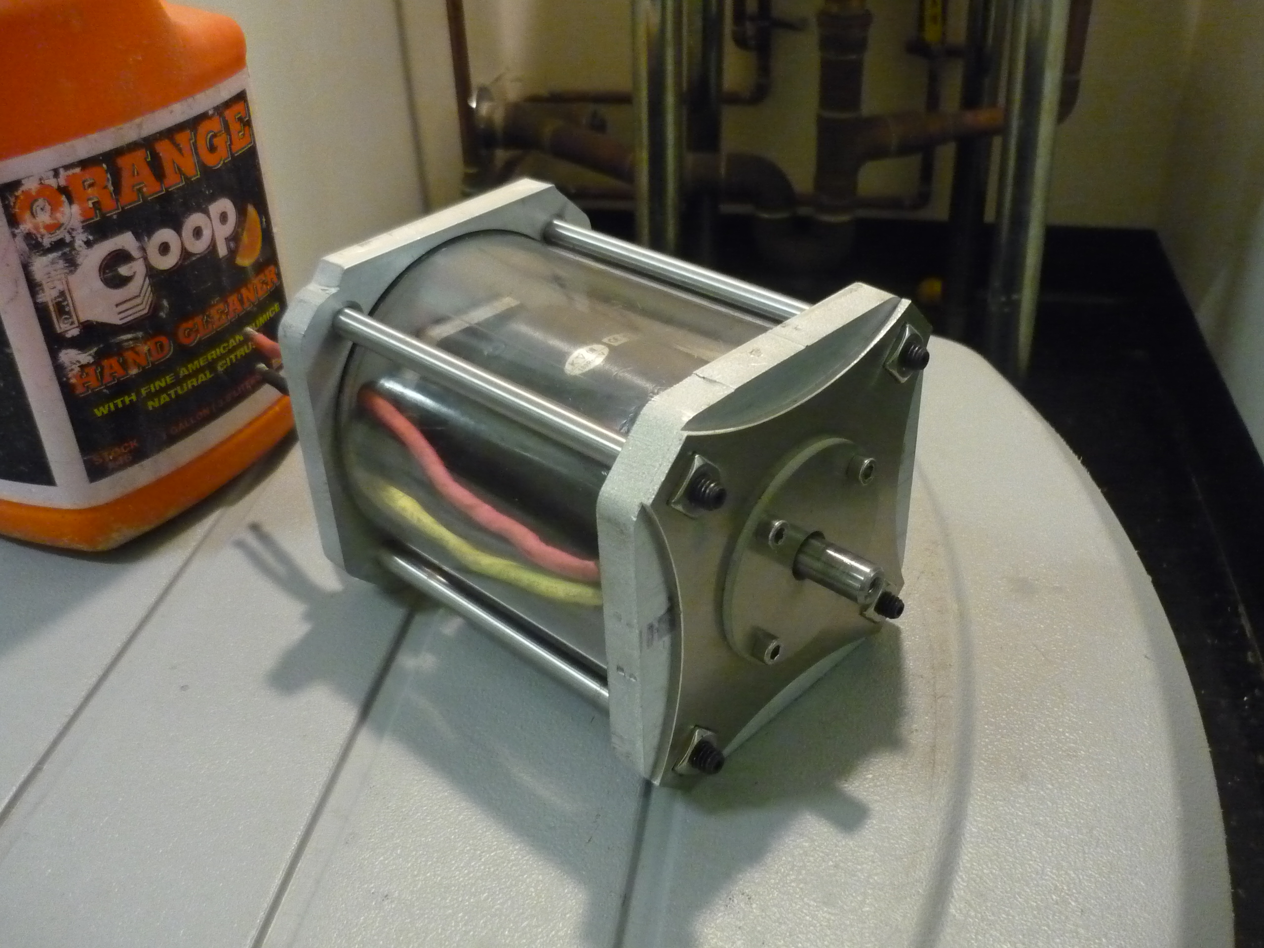
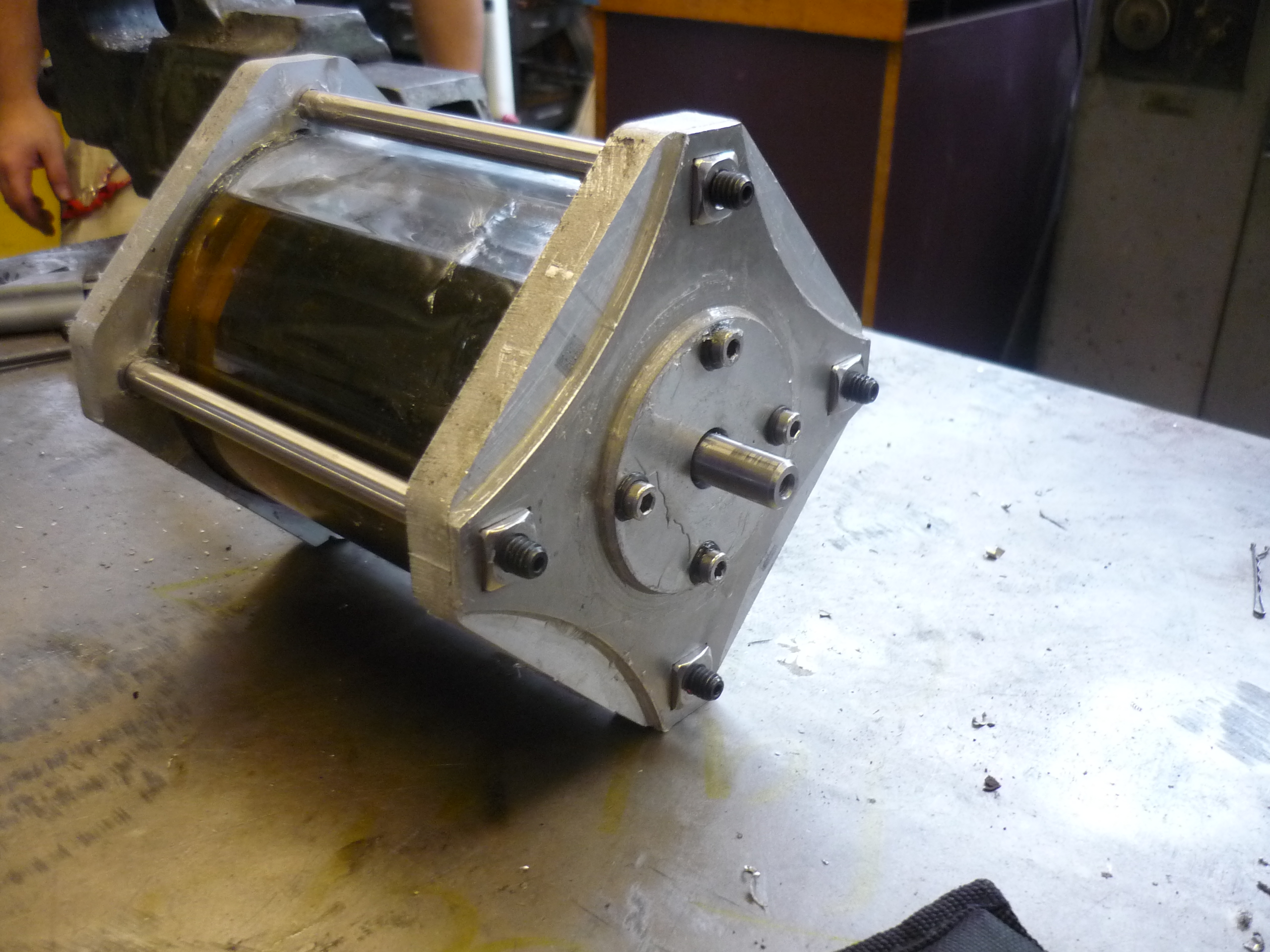
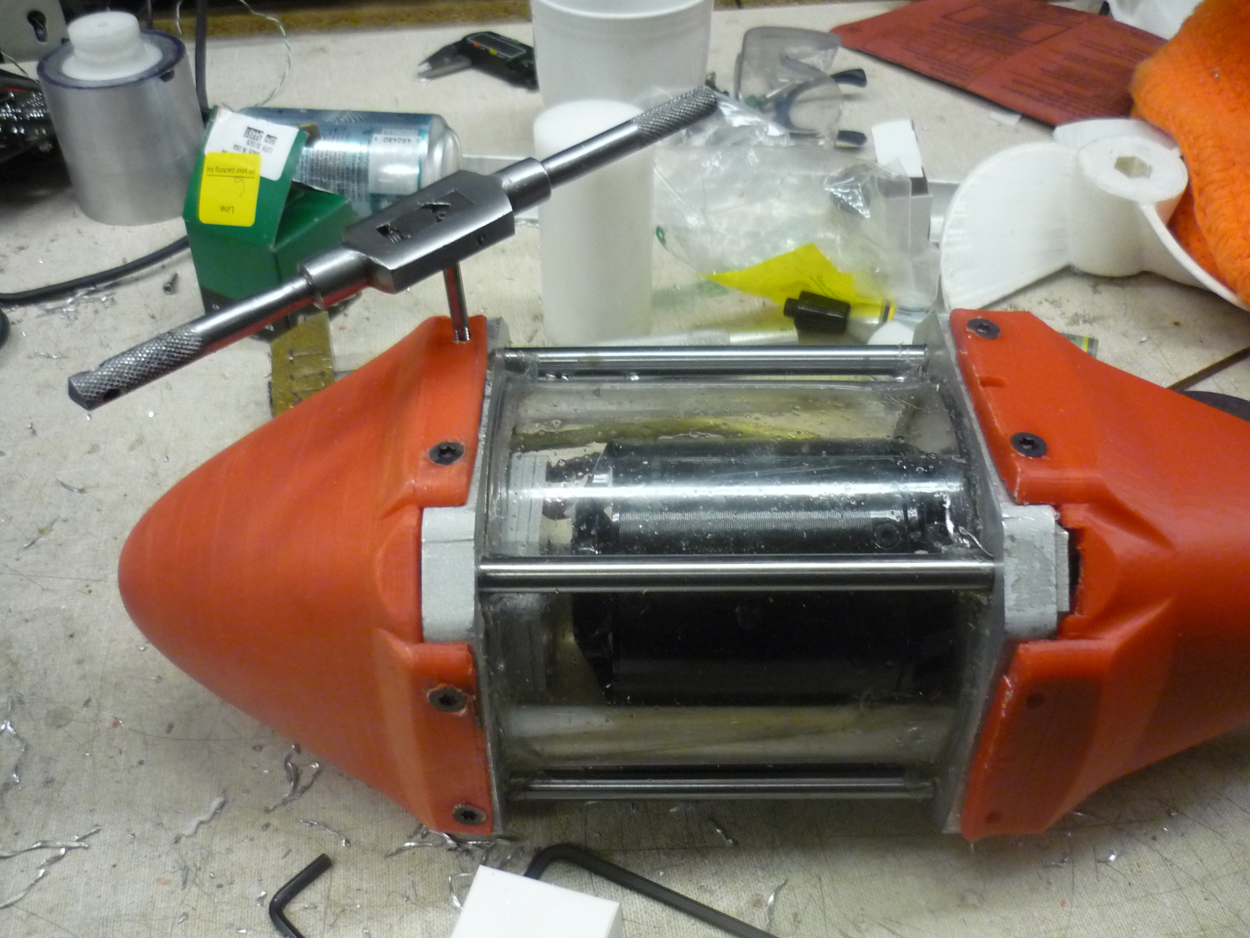
| Ringed-up After approximately an hour, the first 'sealed' thruster assembly was complete. Because i didnt have access to a lathe large enough to cut the polycarb tube, i rough-cut it on a bandsaw. Note the sealed wire-pass-throughs are not installed in this quick setup. |
 |
 |
| Attempting to cut a polycarb tube | ||
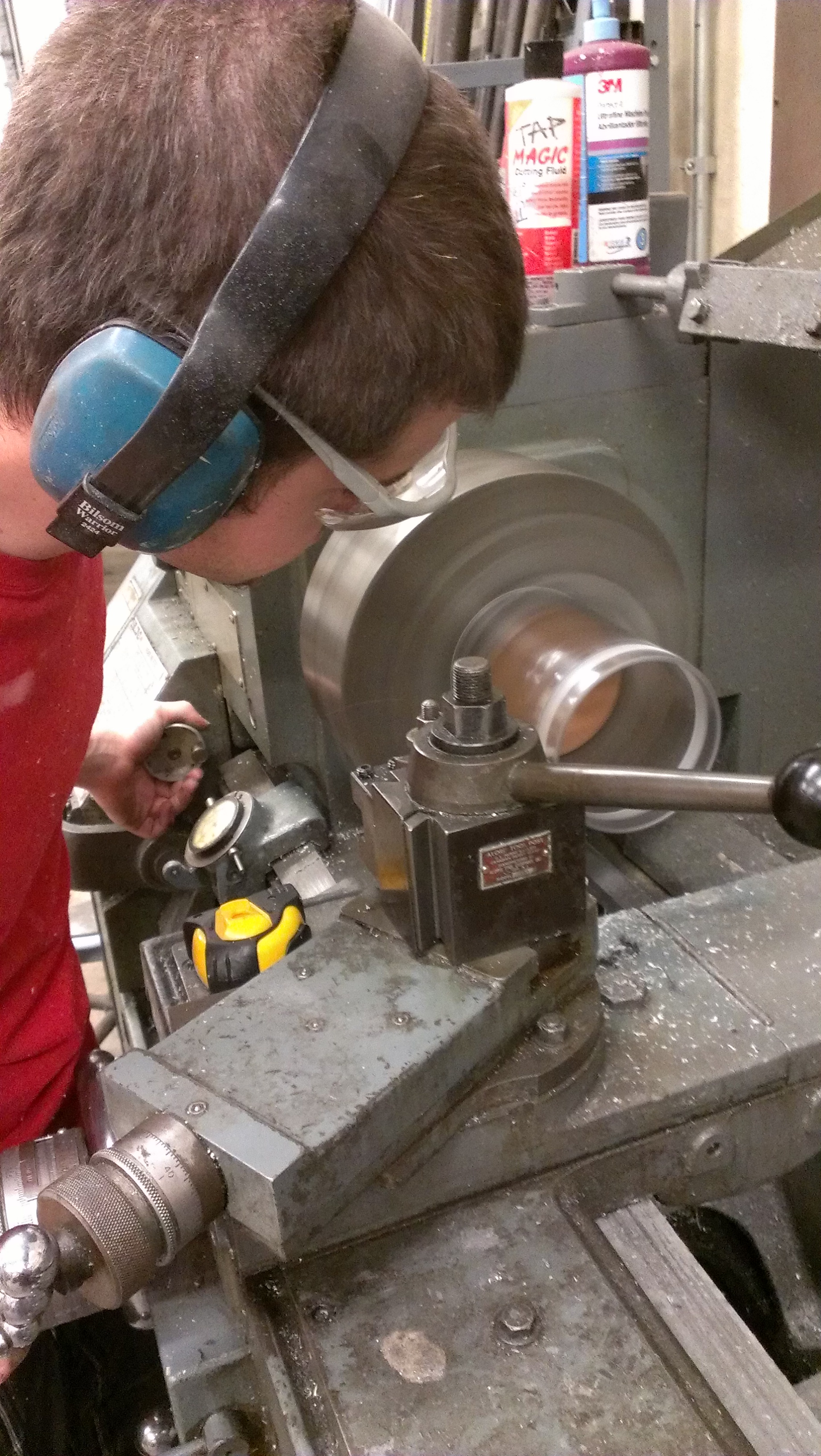
| Polycarb is a bit of a bother I chose polycarb for the thruster-casing as it is both extremely durable and relatively transparent. 1/8" thick polycarb unfortunately is fairly easy to deform, especially under pressure from a momentous lathe. It jumps out of small lathes if you sneeze, and deforms under pressure. BEHOLD the LeBlonde, maniacal in both power and functionalities. I began with a 3-jaw chuck and some custom mounting hardware to keep the tube in shape during the cut. |
 |
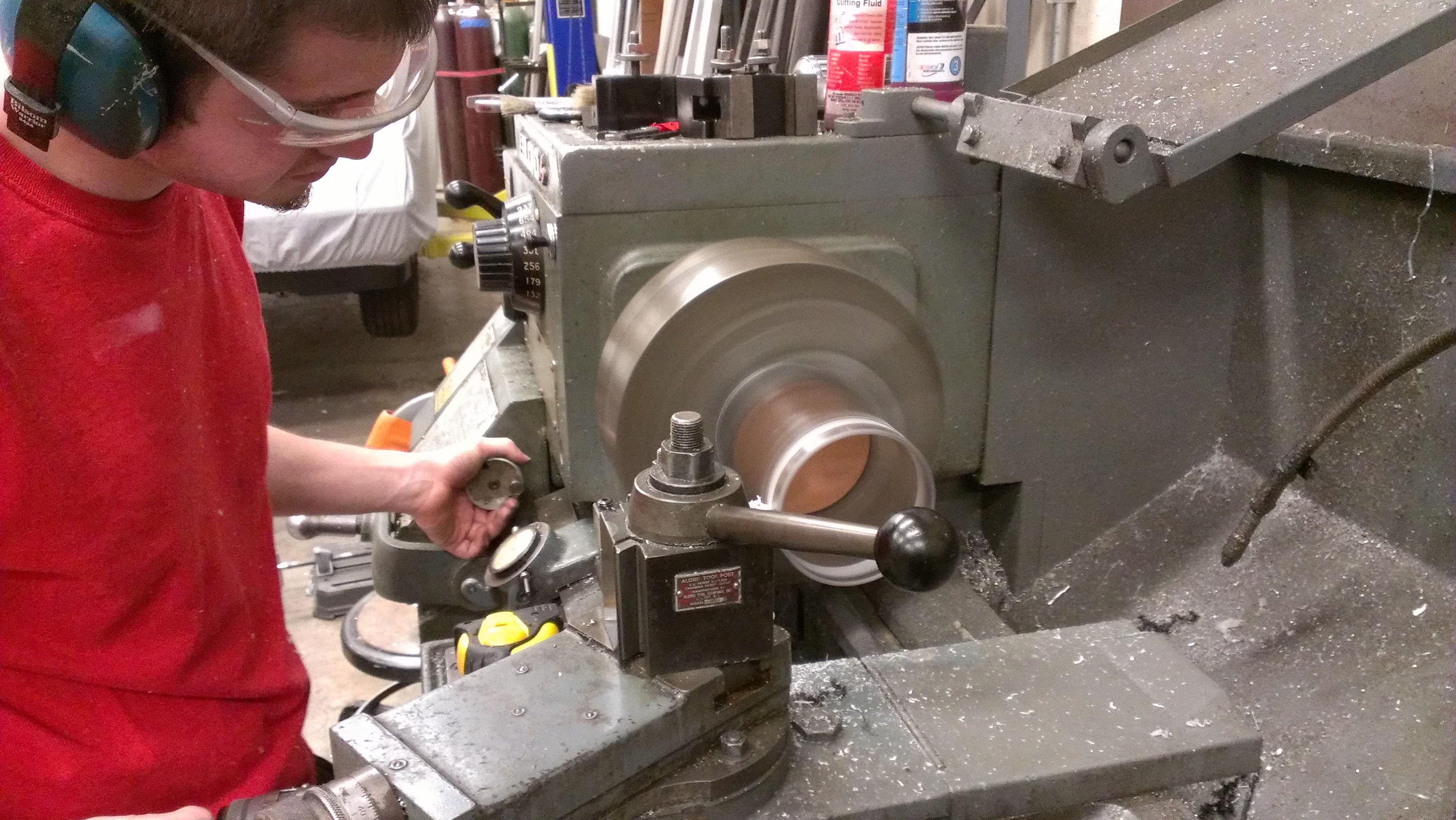 |
| Tube
mounting hardware I was fortunate enough to have access to a nearby lasercutter (thanks uncle charles). Using some scrap MDF, I cut a dozen circles, sized to make a tight fit to the walls of the container. Using some hot-glue, and laminating circles together, I made a round ingot of wood, which had enough compressive response to prevent the three-jaw chuck from crushing the tube. Lathing happened on a very very high speed (to not torque the delicate apparatus) and tenaciously slow tool feed. After about 20 minutes of, ever-so-slowly cutting into the part, the scrap end jumped off and hopped around the shop. After some edge-cleaning I had a semi-precise polycarbonate tube! |
 |
 |


| Initial testing: Viscous sheering | ||
| I
wanted to verify that the setup, which now could hold its own against
water, could 'hold in' some fairly slippery oil. As I did not have
anything fancy at hand, i was able to purchase some 5W-20 oil from a
nearby gas-station. Oil and Oil ratings are a bit odd. Fortunately wikipedia [gave a hand]. The first characteristic is viscosity. SAE ratings rank from 0W to 60, 0 being the lowest viscosity, 60 being the highest (most molasses-like).. |
 |
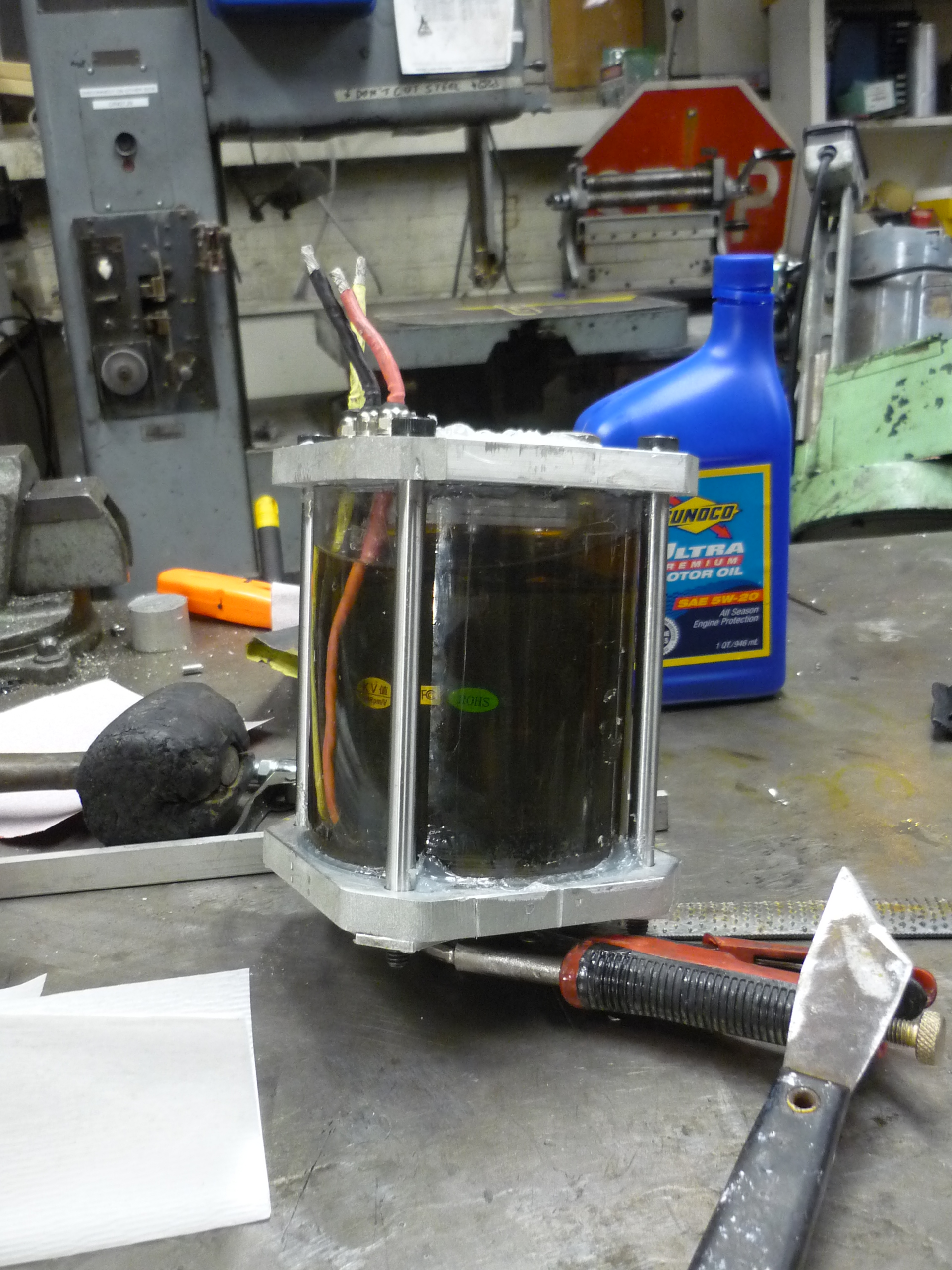 |
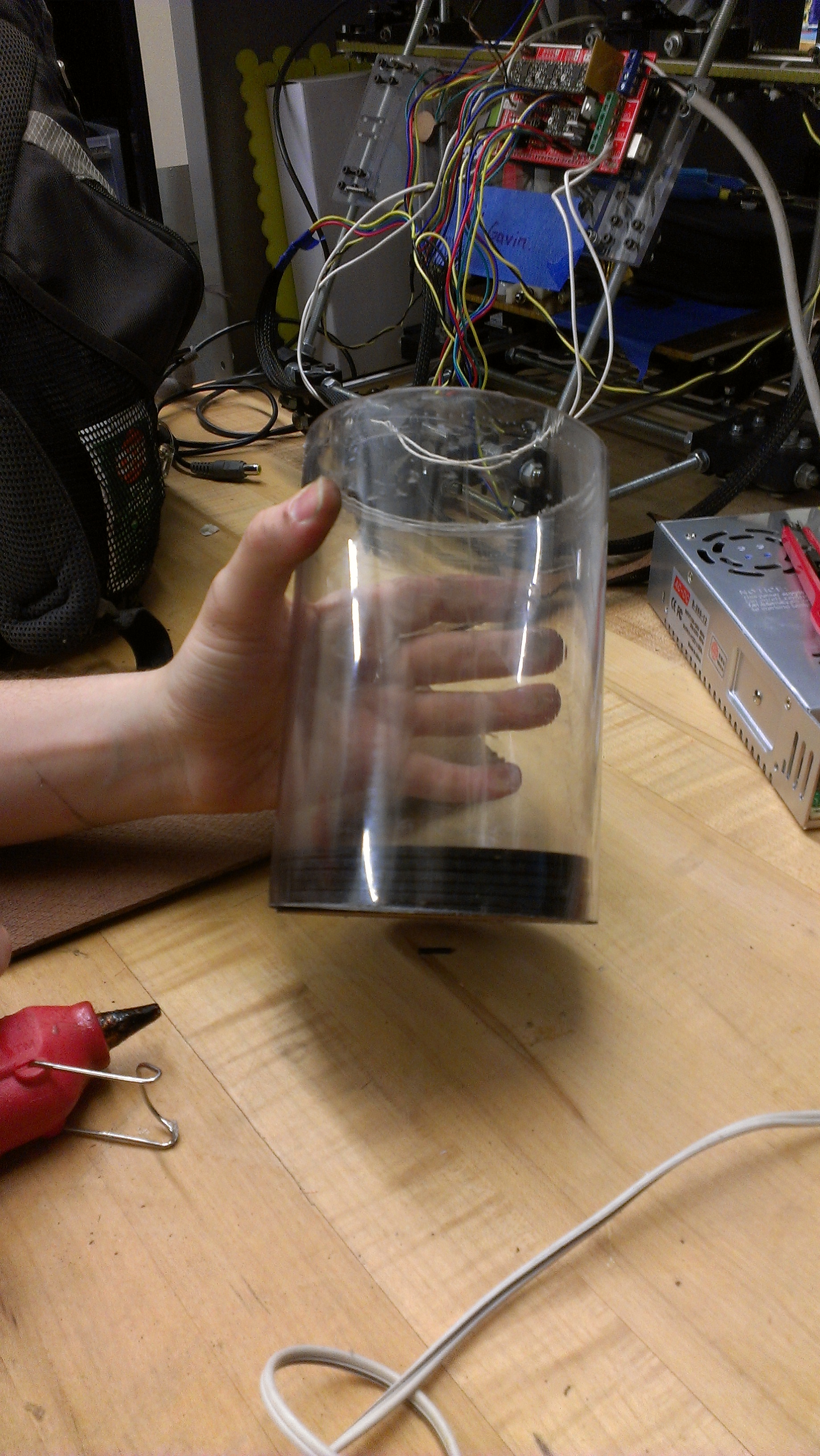
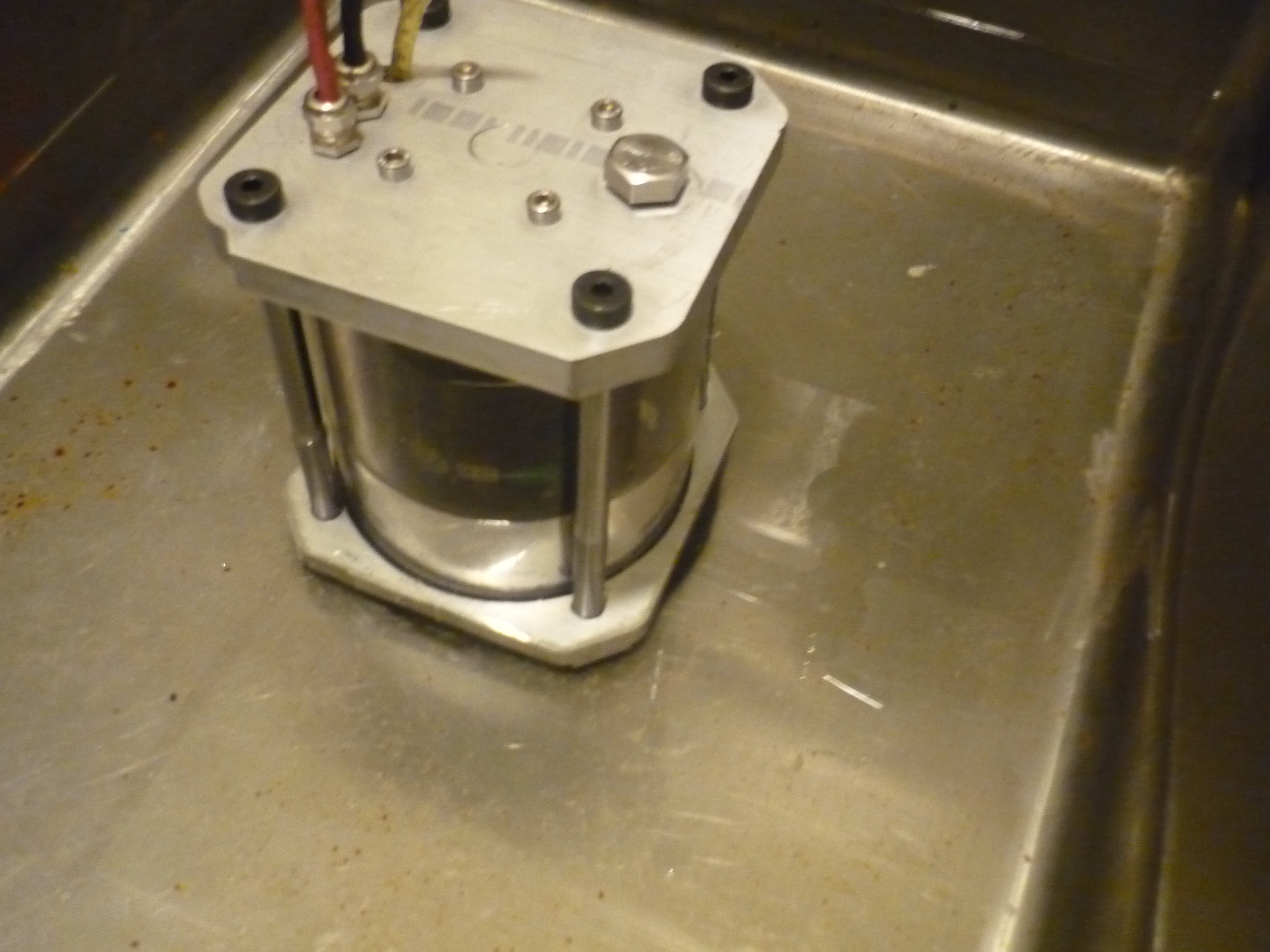
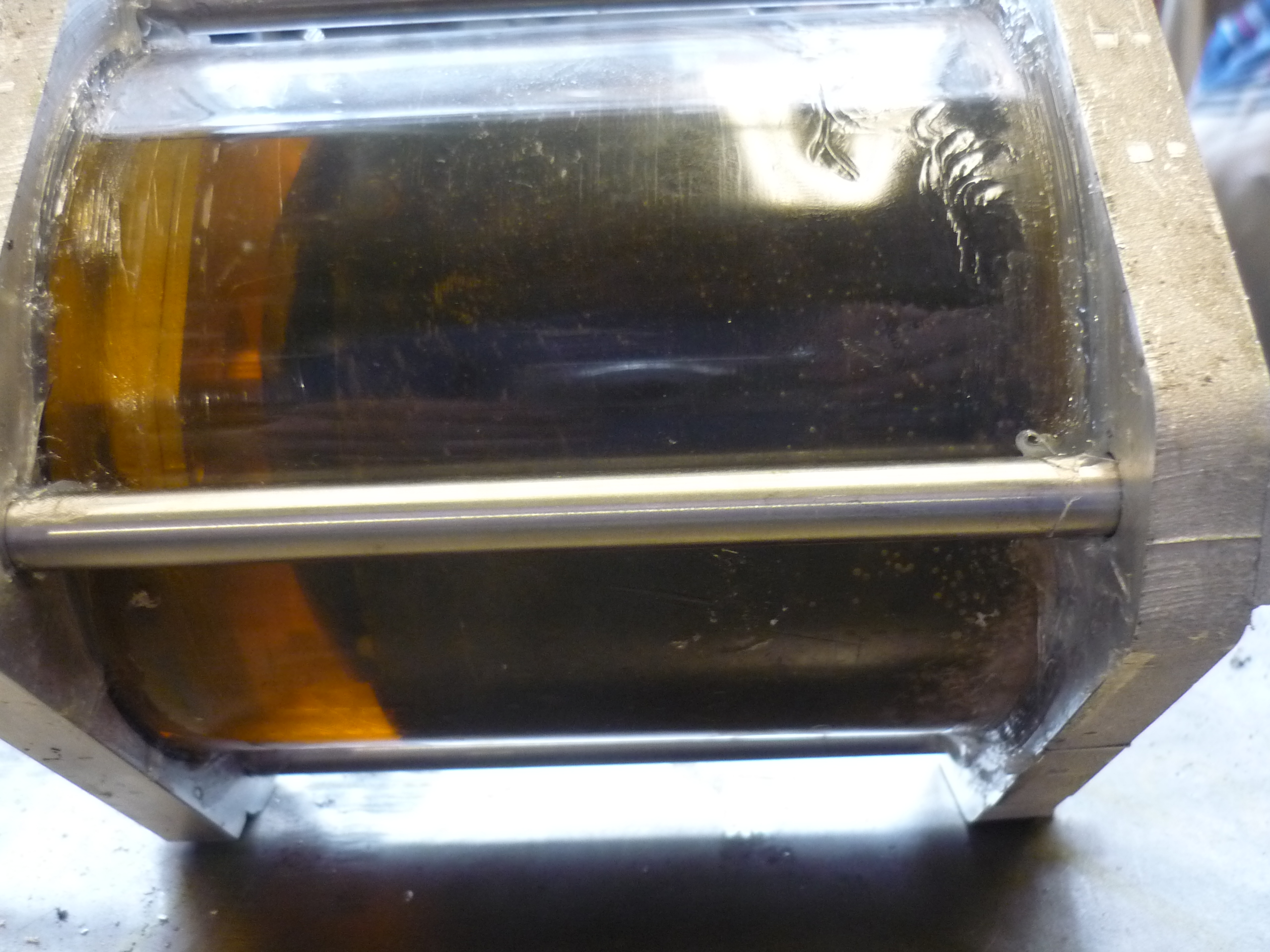
| After fill up, 90% of the way,
I
let the motor sit, and waited with baited breath to see if anything
precipitated out. Noting leaked, no drips from the shaft-seal, no oozing from the 5mm bolts!. Much rejoicing was to be had. The oil is a bit hard to see through, which, was a bit sub-optimal for a see-through housing. |
 |
 |
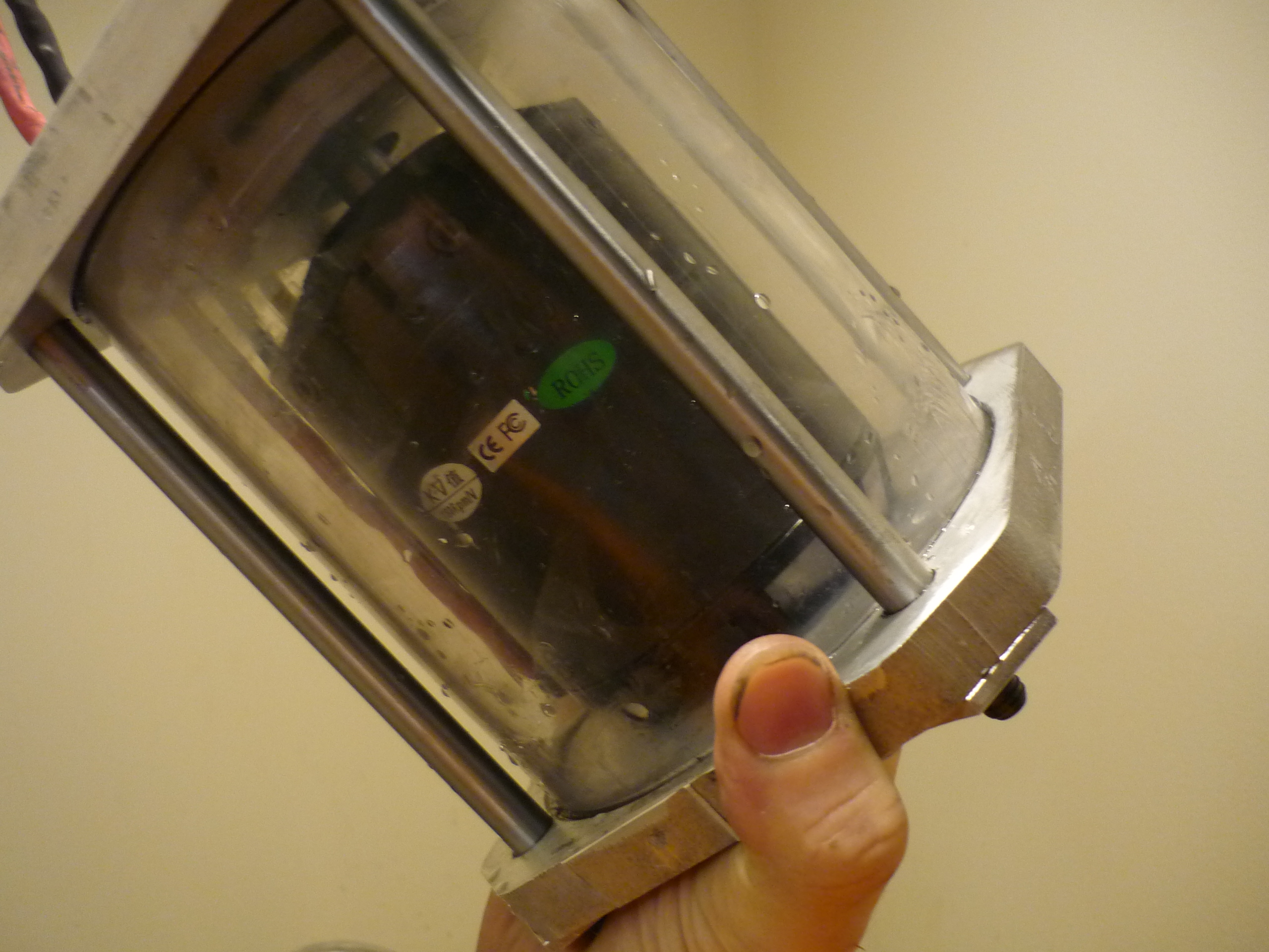
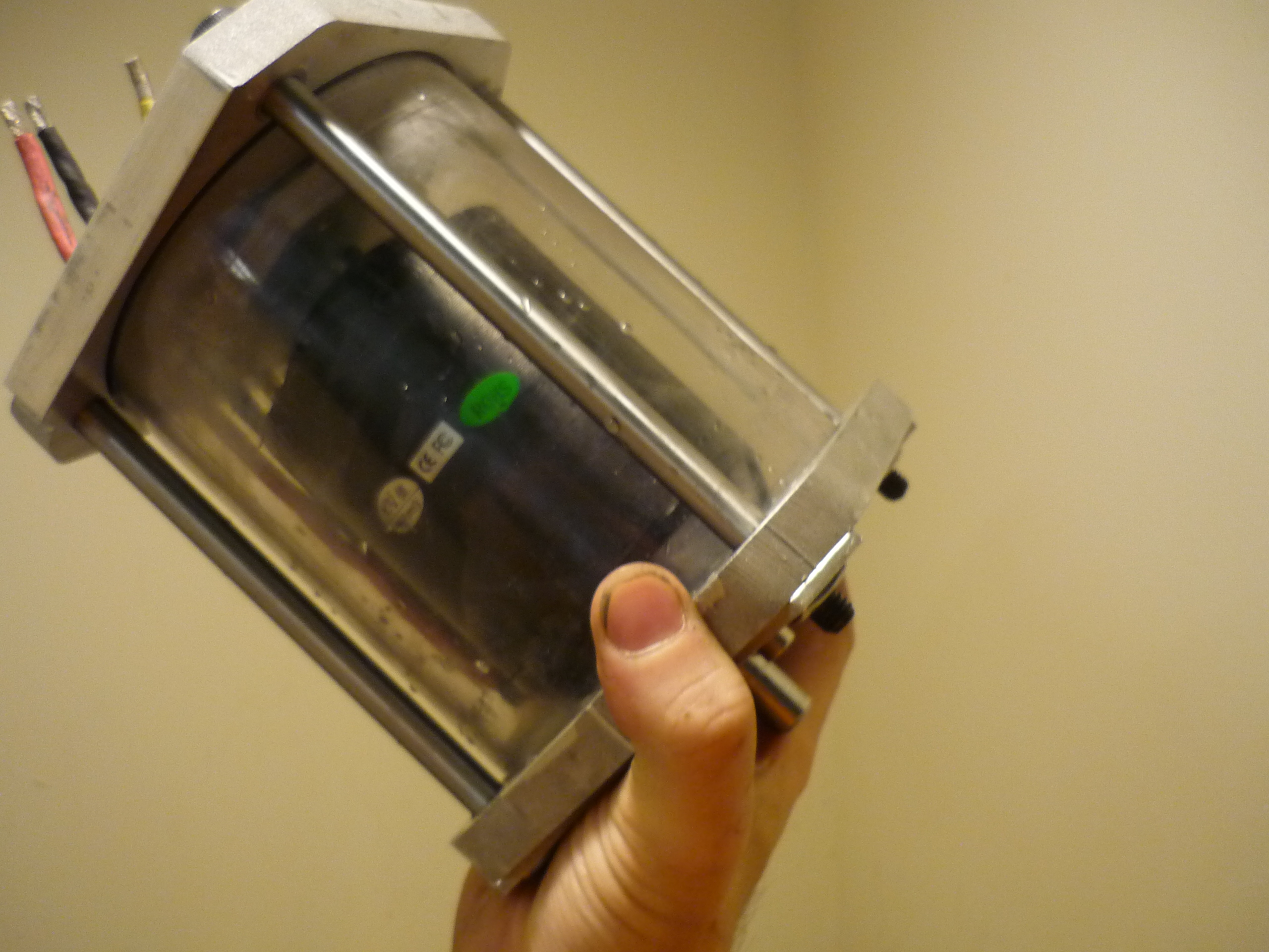
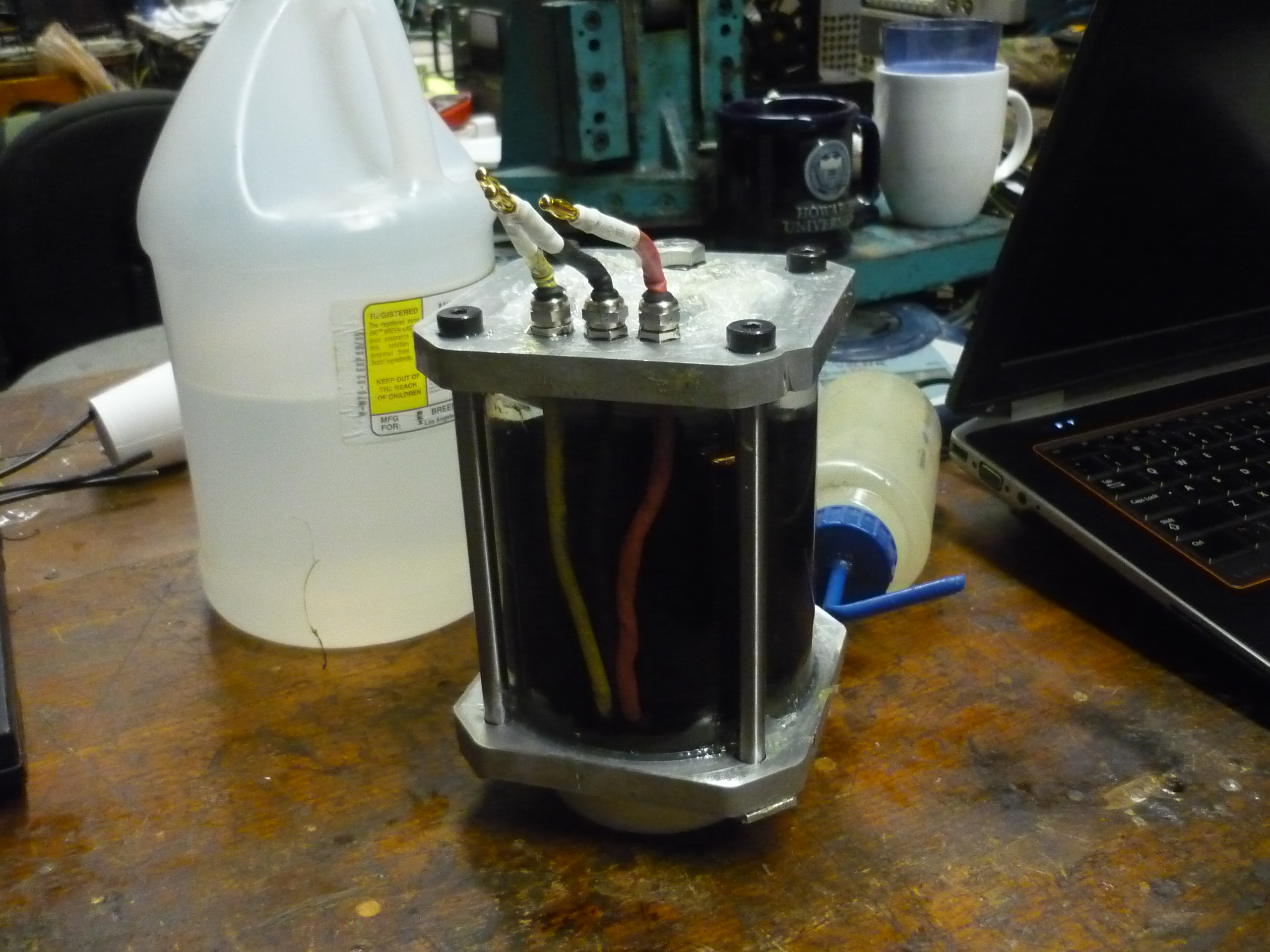
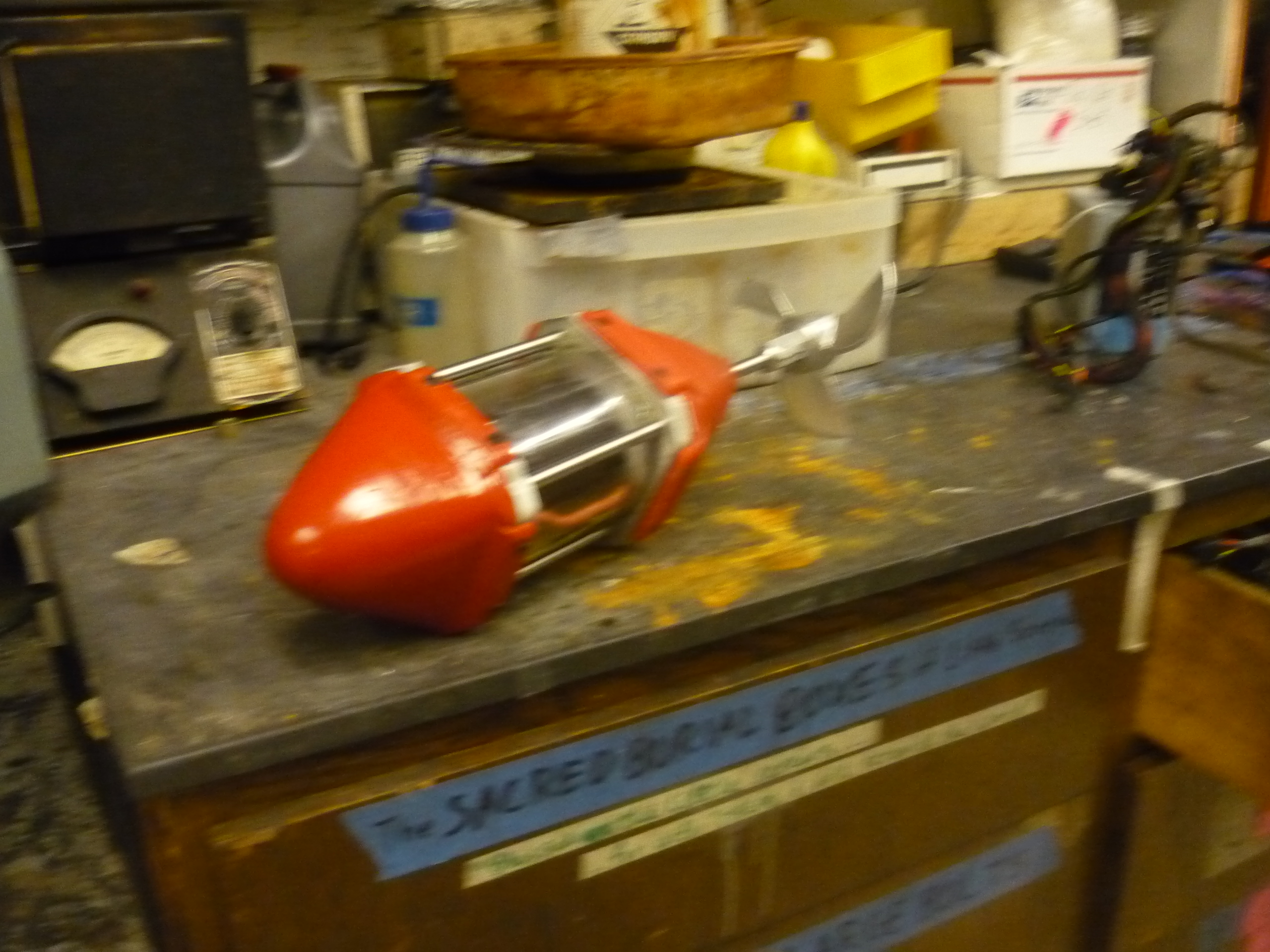
| EXCITING
photos of the first sealed drive It's holding the fluid and looking snazzy. |
 |
|
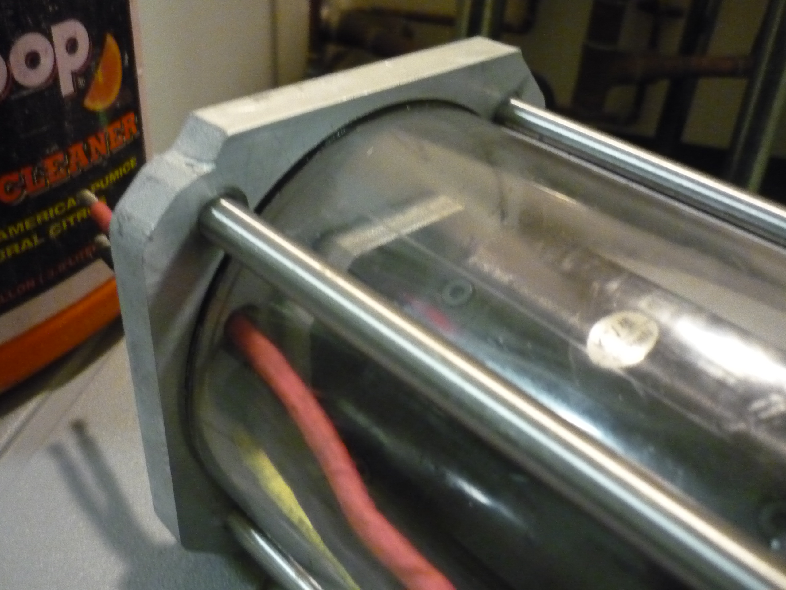
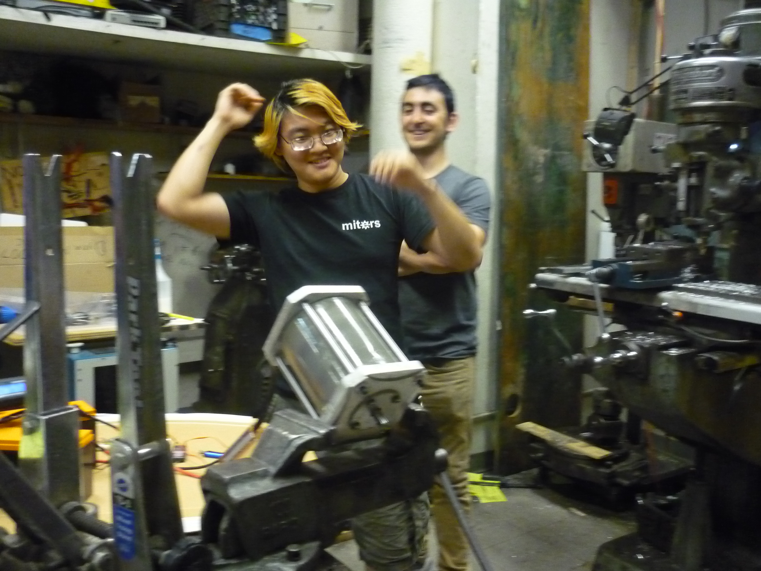
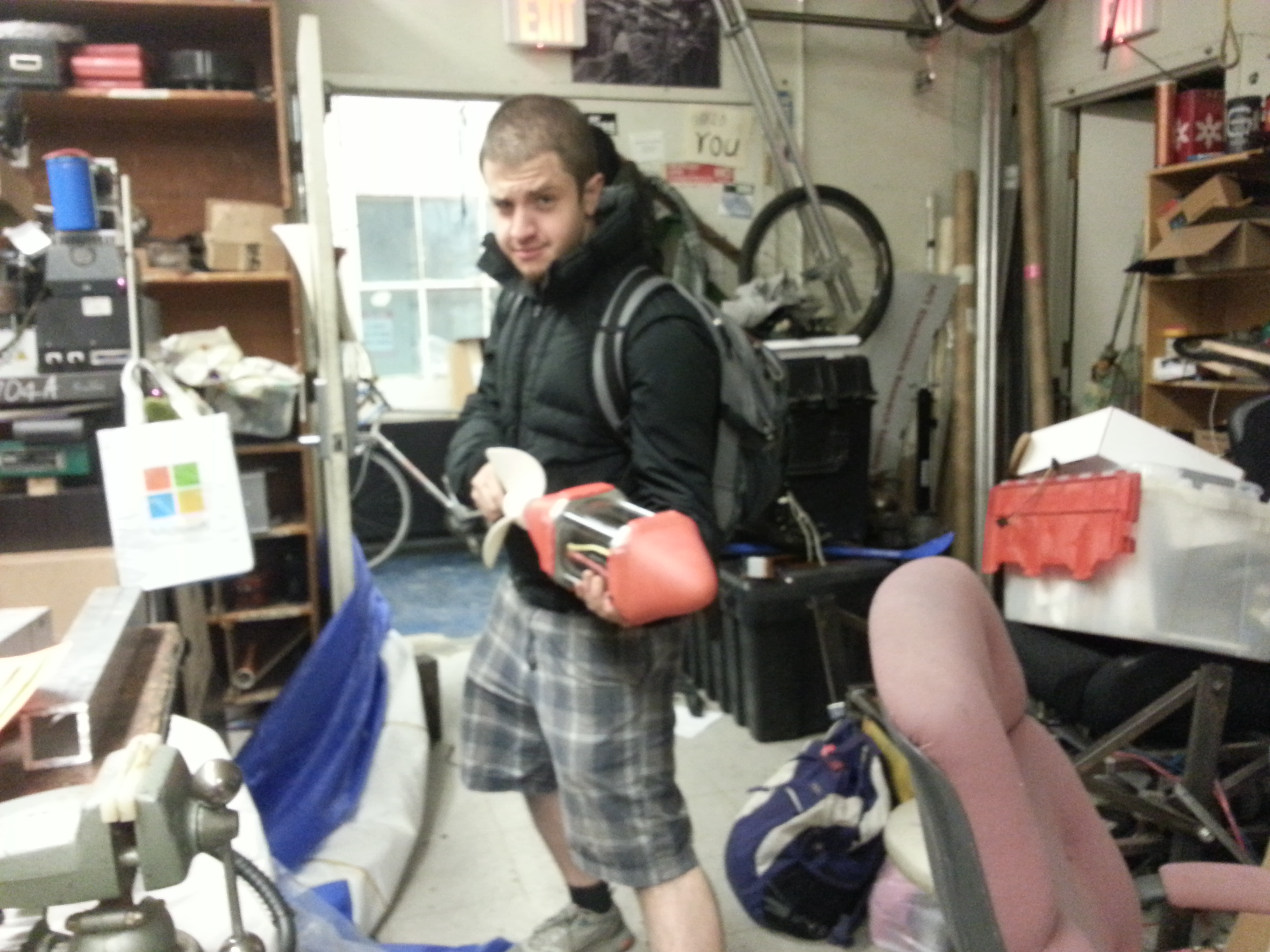
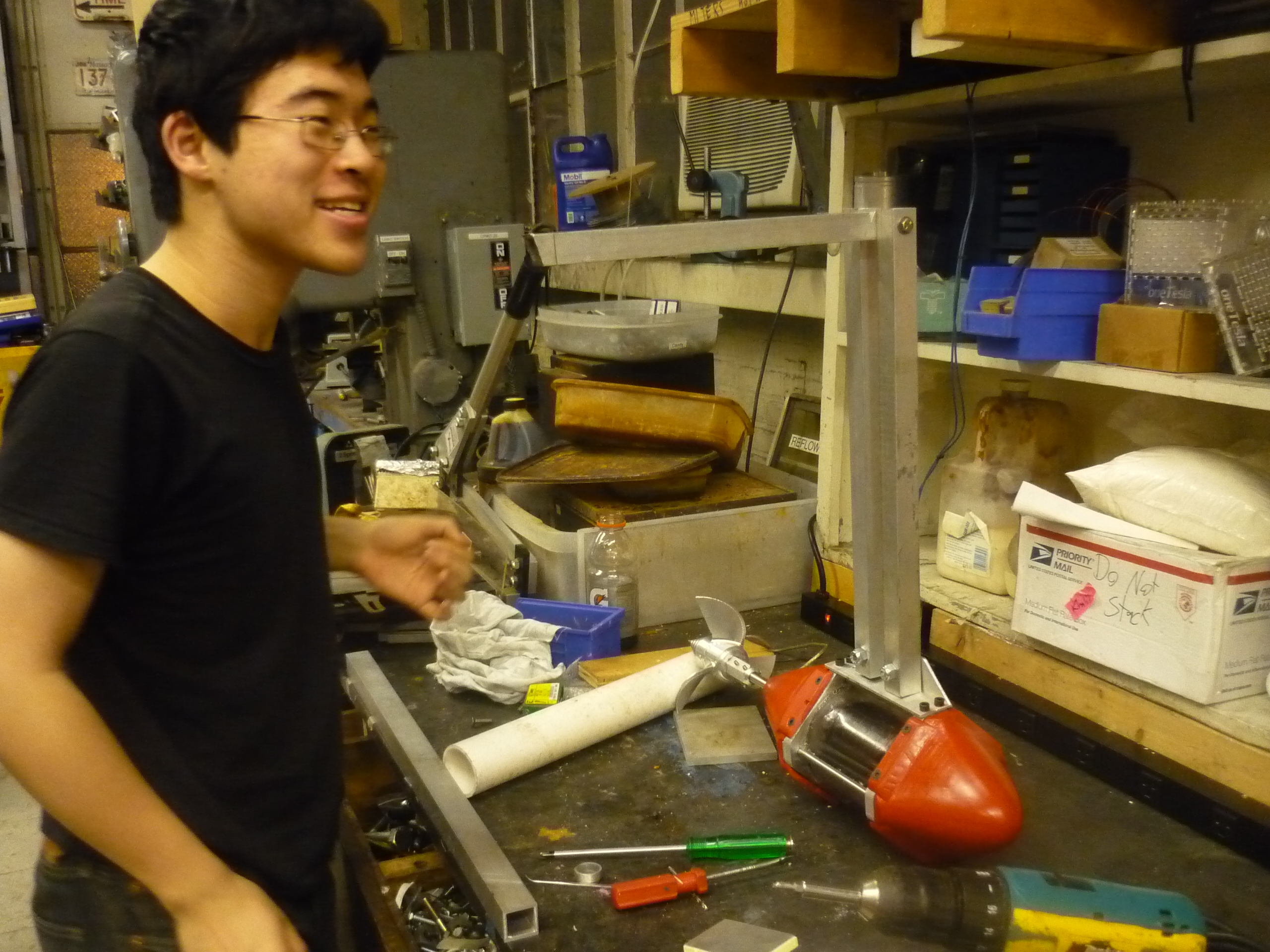
| EVEN
IN A VICE: ITS FRIGHTENING The very excellent Adam Bercu [Fluxwonderland] and Charles Guan [Equalszero] witness the first spoolup of the beast. |
 |
|
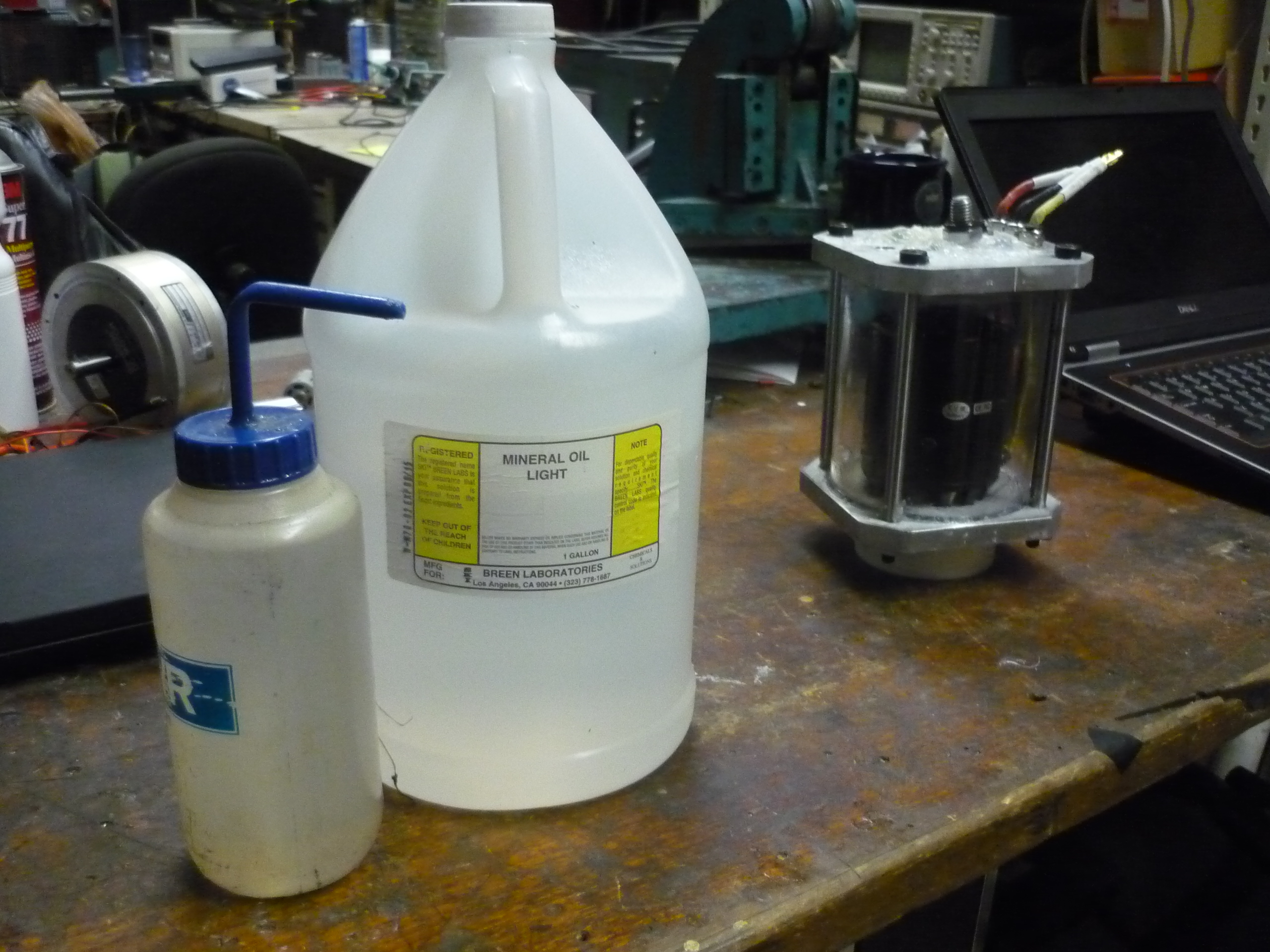
| Much
better: Mineral Oil What is mineral oil? Its generally a petroleum distillate, that can be non-toxic (or even food-grade). Its non-conductive, displaces water and is non-compressible. It's also a fairly decent lubricant. Unfortunately its lubricity can vary, there appears to be a plethora of types ranging from 'thick' to 'horse laxative'. I found a gallon of 'light' mineral oil, and determined it would be worthwhile to test. I used Breen Light mineral oil for the fist test. Its clear and makes the assembly look fairly fantastic. |
 |
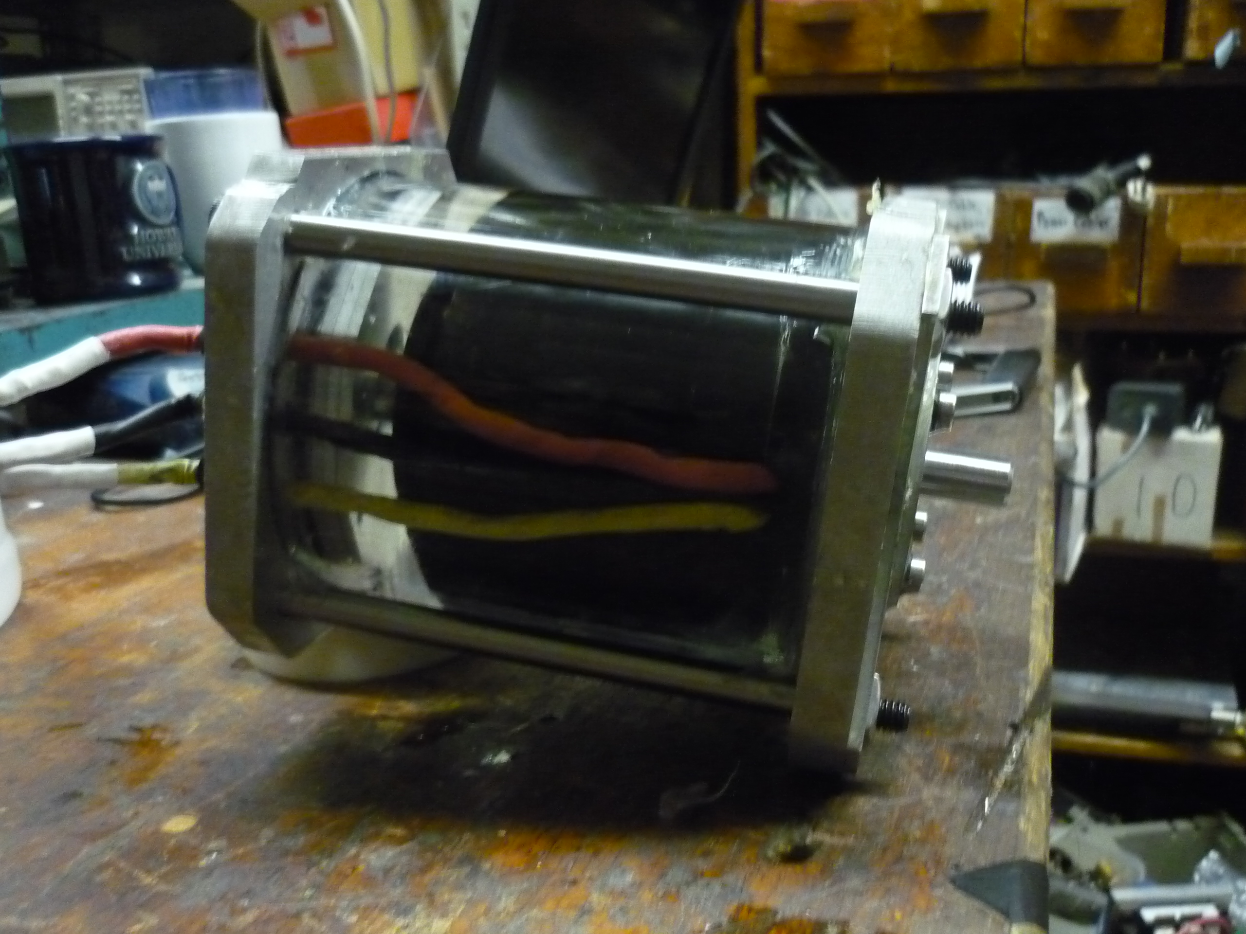 |
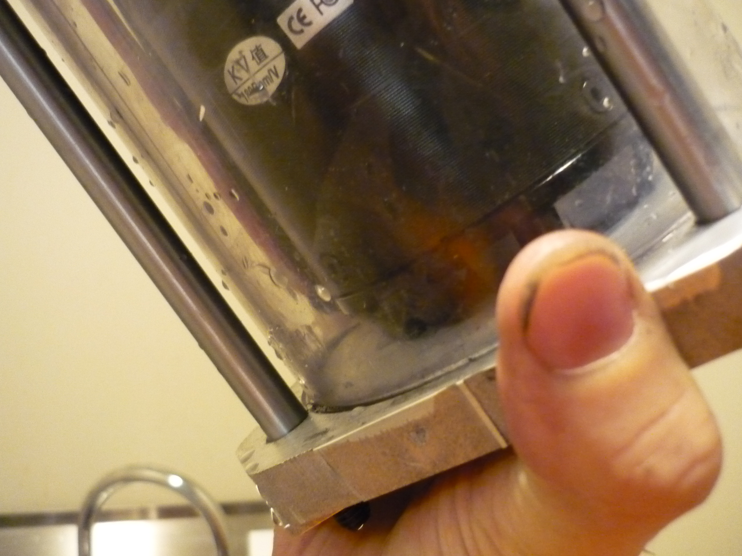
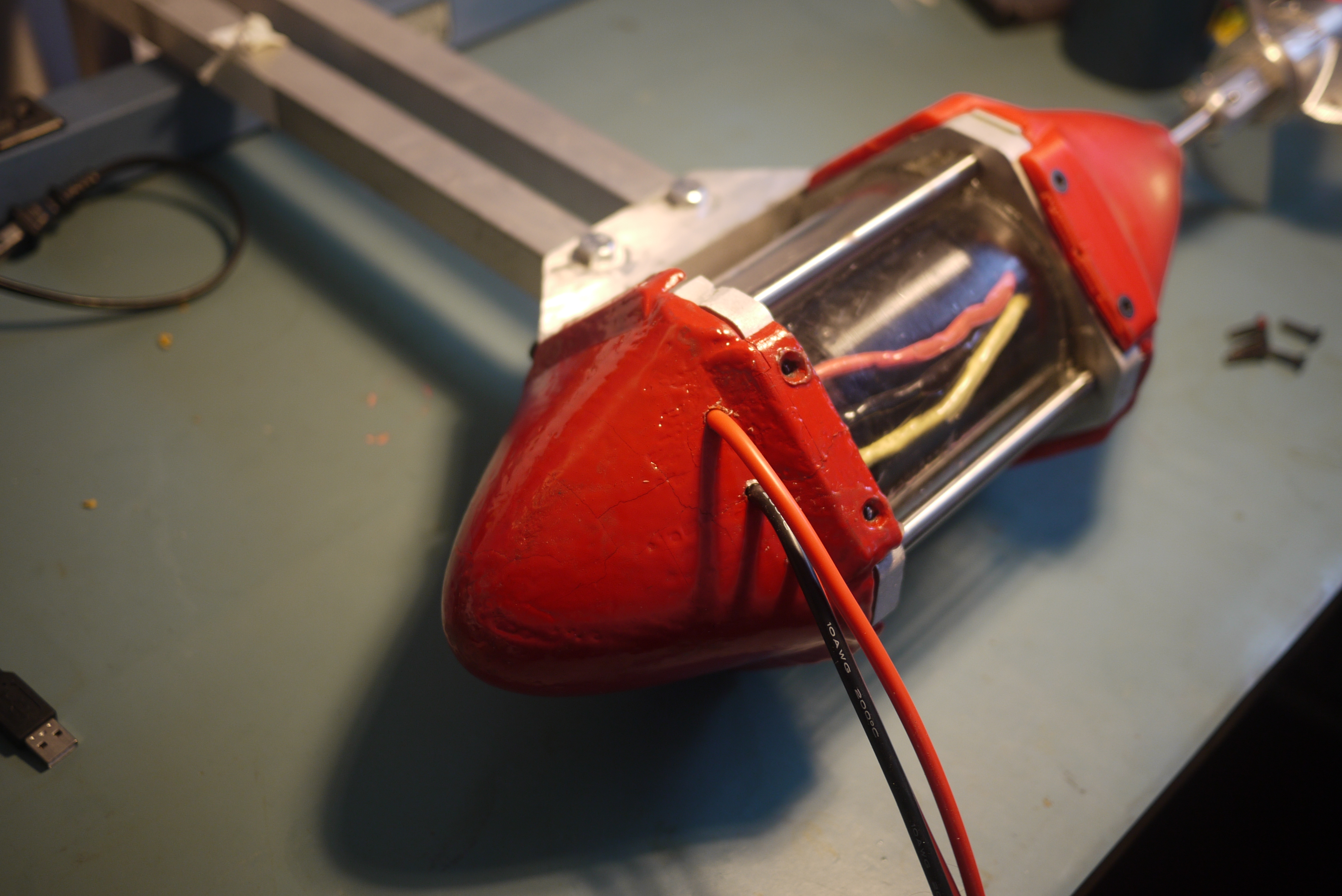
| An
Interesting side-view Some of the residue from the 5W oil was leftover when I first filled the thruster assembly. This resulted in the clear oil having a bit of a murky characteristic. Interestingly, it was not until the assembly was fully filled that the motor was fully visible. Note, by the time of filling, the remaining wire seal components had arrived. |
 |
 |
| First Spoolup Test |
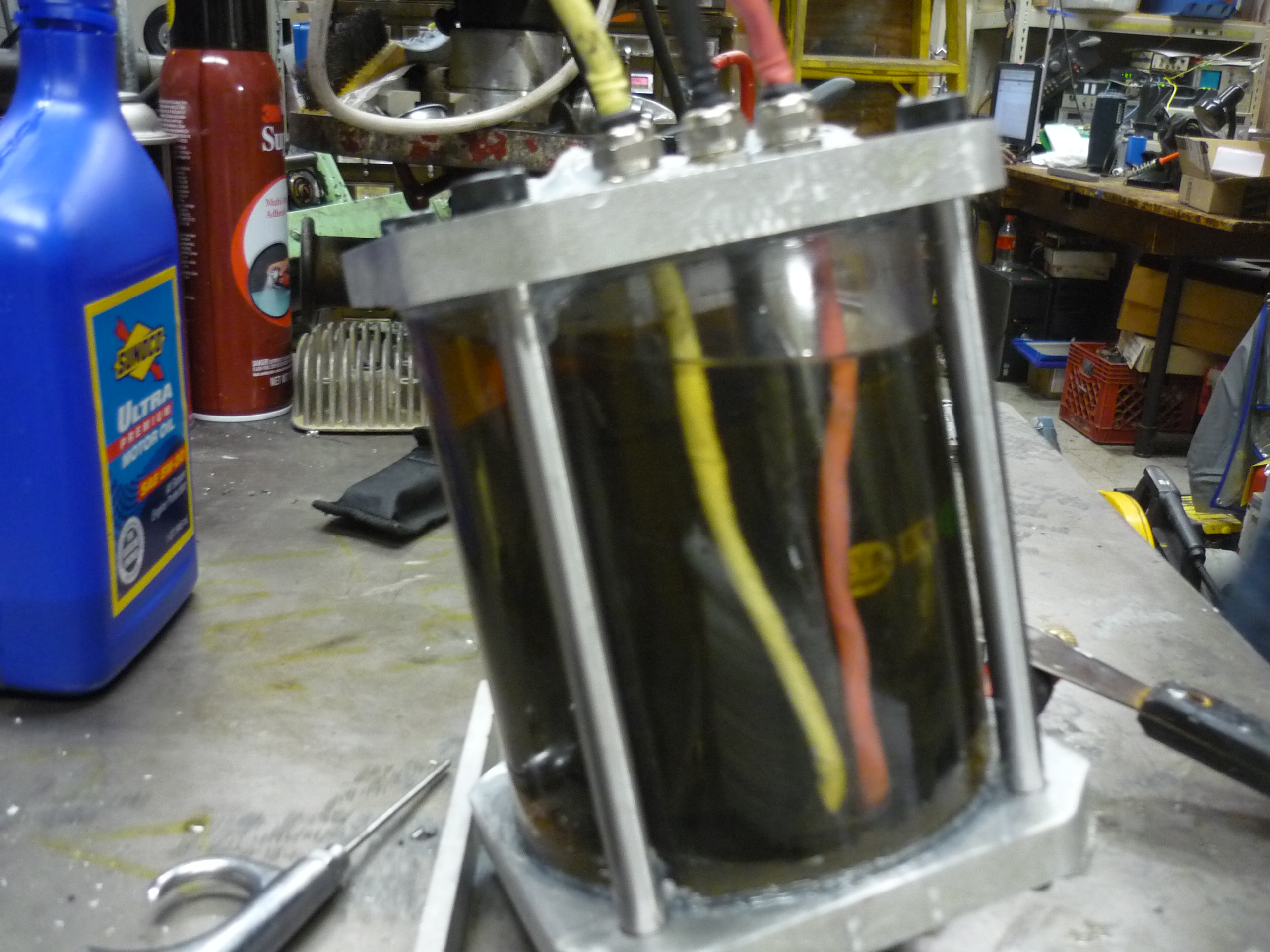
| After
the motor was
assembled a number of tests were run on the assembly to determine
static loss tests on the motor operation at variable speeds and with
different liquid lubricants. Charles G [etotheipiplusone]
and Adam B [fluxwonderland] witnessed the
birth of the beast. Initial testing was completed using a sandcastle
100A ESC controller running on three A123 battery brick assembly. a
130A in-line watt/power meter was used for energy loss estimates. |
Bill of Materials
| Note, the parts selection for this project favored off-the-shelf components to allow easy replication / duplication / incremental improvements. 'Unobtanium' items were kept to a minimum, and waterjet parts can be ordered through bigbluesaw. |
| CAD Implementation | Part Description | Manufacturer PN | Vendor | Quantity | Part Details |
 |
Outer Clear Polycarb Housing | 8585K78 | mcmaster-carr | 1 (ft) | Impact-resistant Polycarbonate Round Tube, 4-1/2" Od, 4-1/4" Id, Clear |
 |
Sealed bearing, pressed between motor assembly and 1/2" output plate | 5972K42 | mcmaster-carr | 2 | Metric Steel Ball Bearing, Double Sealed Bearing No. 6201 For 12mm Shaft Dia |
 |
Giant Shoulder-bolts which clamp together motor assembly | 91259A114 | mcmaster-carr | 4 | Alloy Steel Shoulder Screw, 3/8" Diameter X 6" Long Shoulder, 5/16"-18 Thread |
 |
9/16ths wide square nuts, locked into retaining flange to allow single-sided fixturing | 92891A200 | mcmaster-carr | 1 | Type 316 Stainless Steel Square Nut, 5/16"-18 Thread Size, 9/16" Width, 7/32" Height |
 |
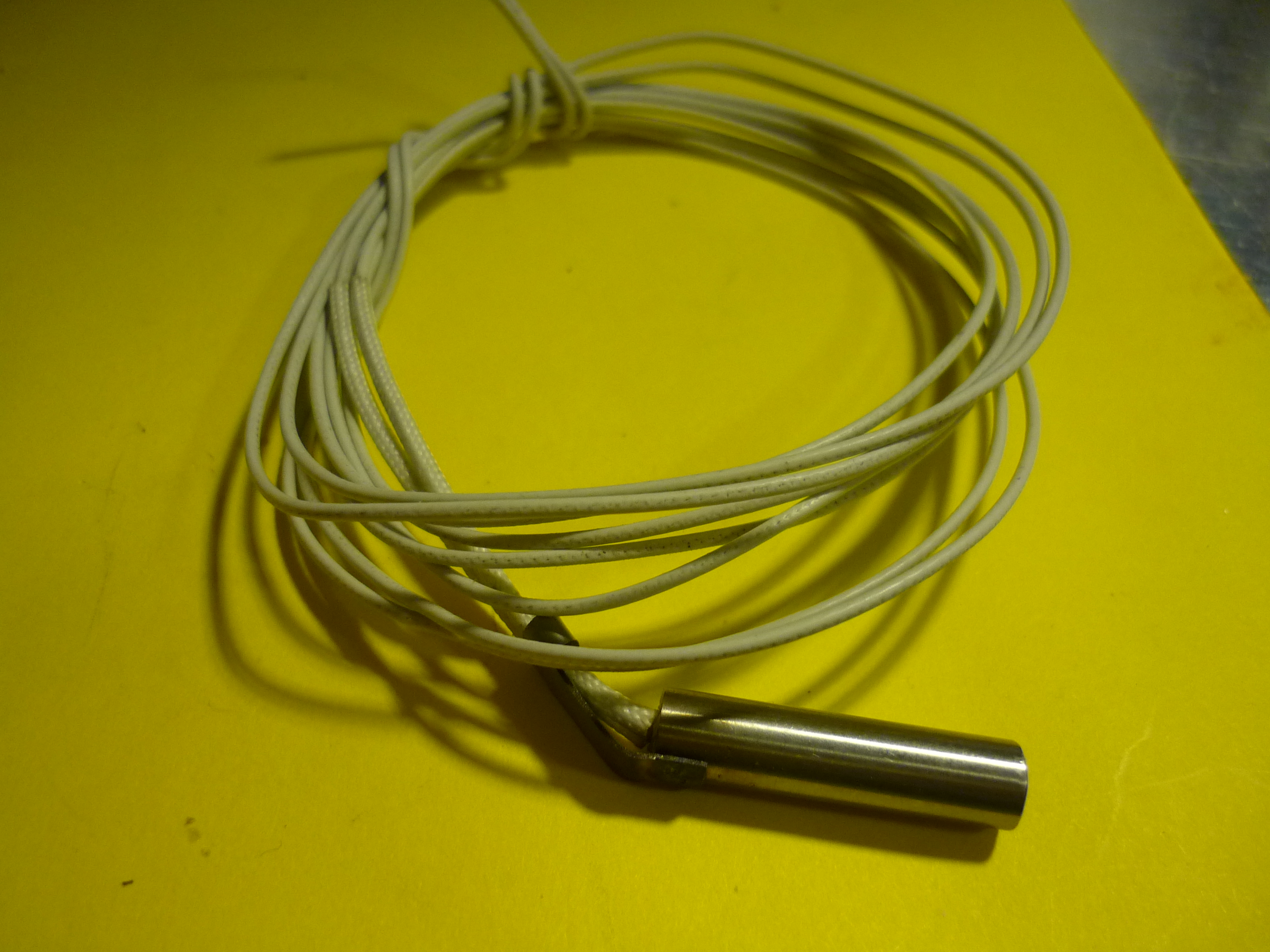
Spring-loaded shaft seal, wedged between the main hull-plate (1/2" thick) and held in place between the motor and the retaining nut assembly | 5154T64 | mcmaster-carr | 1 | Shaft Seal, Spring Loaded, Single Lip, 12mm Shaft, 25mm Od |
 |
M5 Screws, attach motor mount and bearing mount | 92290A252 | mcmaster-carr | 1 (pack) | Type 316 Ss Socket Head Cap Screw, M5 Thread, 25mm Length, .8mm Pitch |
 |
M12 Oil-fill bolt, used M12 tap to connect to 1/2" front plate | 91287A186 | mcmaster-carr | 1 (pack) | Metric 18-8 Ss Hex Head Cap Screw, M12 Size, 16mm Length, 1.75mm Pitch,fully Threaded |
 |
1/8" plate, used for bearing holster and front retaining nut assembly | 89015K18 | mcmaster-carr | 1 (12" x 12") | Multipurpose 6061 Aluminum, Sheet, .125" Thick, 12" X 12" |
 |
Main o-rings for polycarb-aluminum seal. | 9452K194 | mcmaster-carr | 1 | Buna-n O-ring, As568a Dash Number 244 |
 |
1/2" plate, used for front/rear | 8975K436 | mcmaster-carr | 1 | Multipurpose 6061 Aluminum, 1/2" Thick, 5" Width, 1' Length |
| N/A | Used to seal any extra areas | 7327A21 | mcmaster-carr | 1 | Underwater Sealant, High Temperature, 2.8-oz Tube |
| N/A | O ring for the polycarb tube | 9263K767 | mcmaster-carr | 1 | Metric Viton(r) Fluoroelastomer O-ring, 3.5 Mm Width, 12 Mm Id |
| N/A | O-ring for the large oil bolt | 9263K121 | mcmaster-carr | 1 | Metric Viton(r) Fluoroelastomer O-ring, 1.5 Mm Width, 5 Mm Id |
| N/A | Bulkhead passthrough | 8183K7 | mcmaster-carr | 4 | Miniature Liquid-tight Cord Grip, Buna-n Seal, M10 X 1.5 Thread, 0.16"-0.24"cord Dia |
| Bill of materials For download: [CSV] [XLS] |
PART II: Outer Shell, nose-cone & inner support bearing assembly
| NOW TO MAKE IT HYDRODYNAMIC |
 |
| Epoxy and ABS | ||
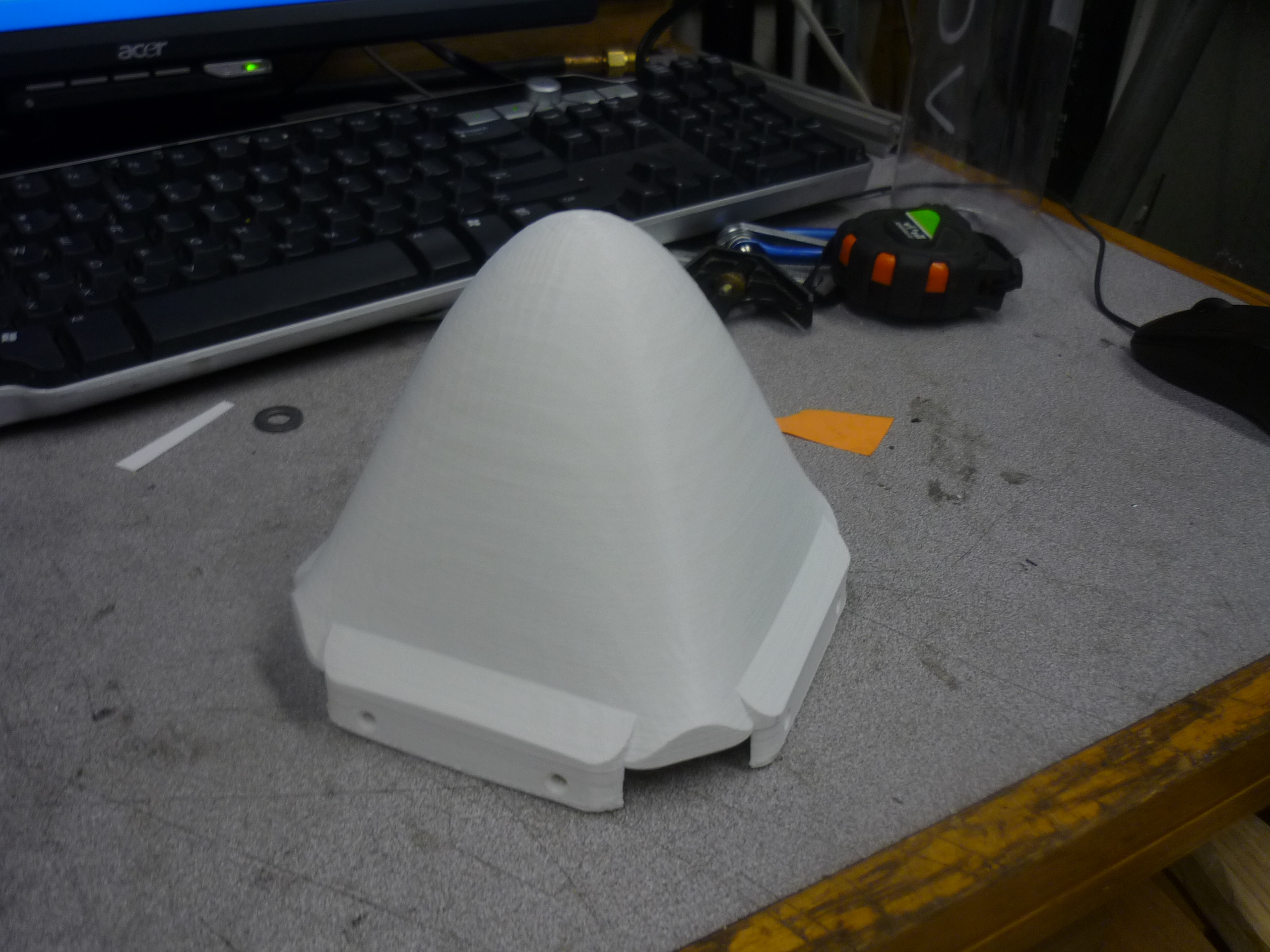
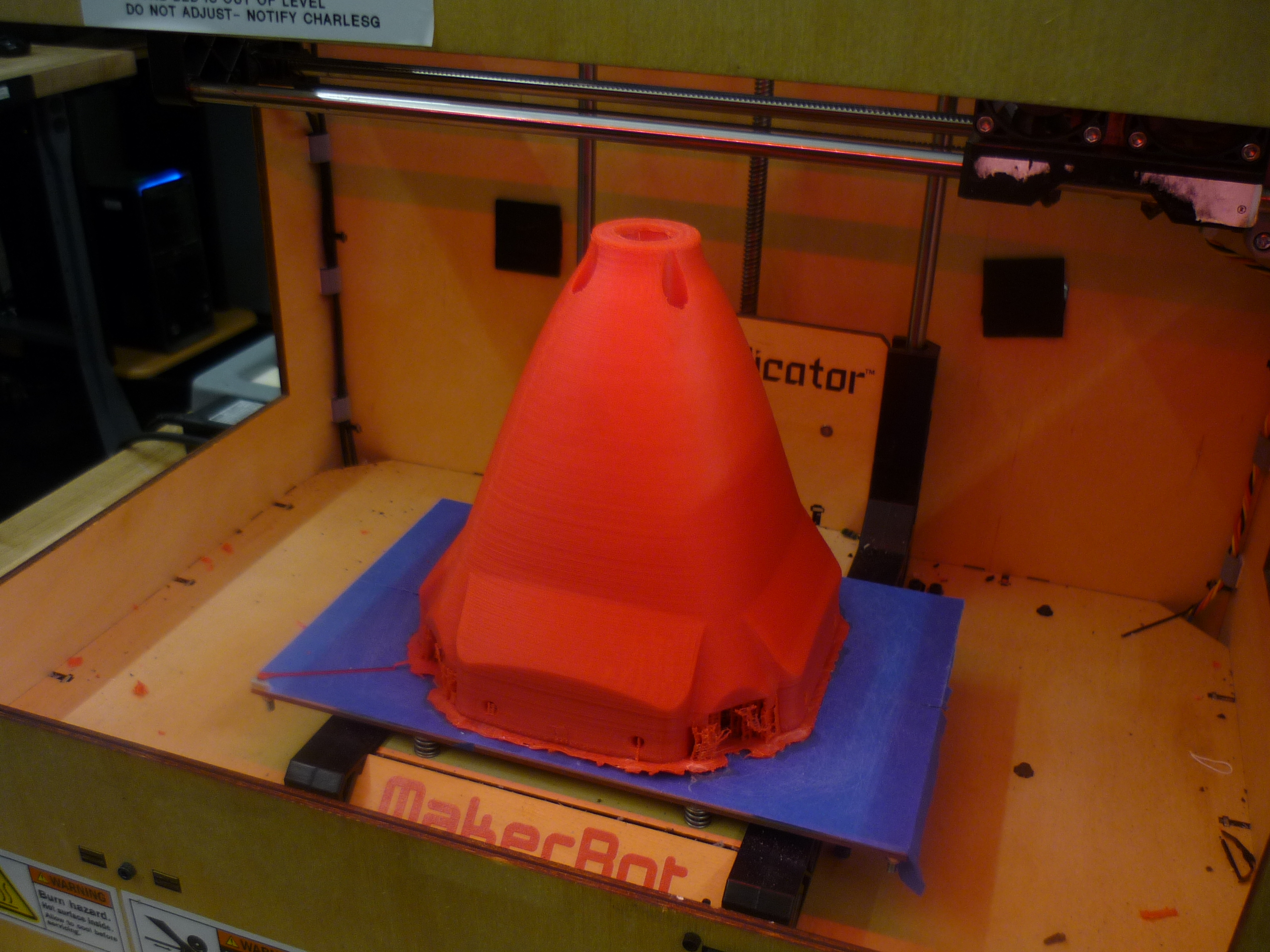
| The
Nose I designed the nosecone to be structural, removable and protect the motor mechanicals while sloshing water out of the way. Both the nosecone and the end cowling were designed to just fit in a standard makerbot replicator build area. I printed one with low fill (shown right) and test-fit the part, made modifications and printed a red ABS version using my home-contraption. |
 |
 |
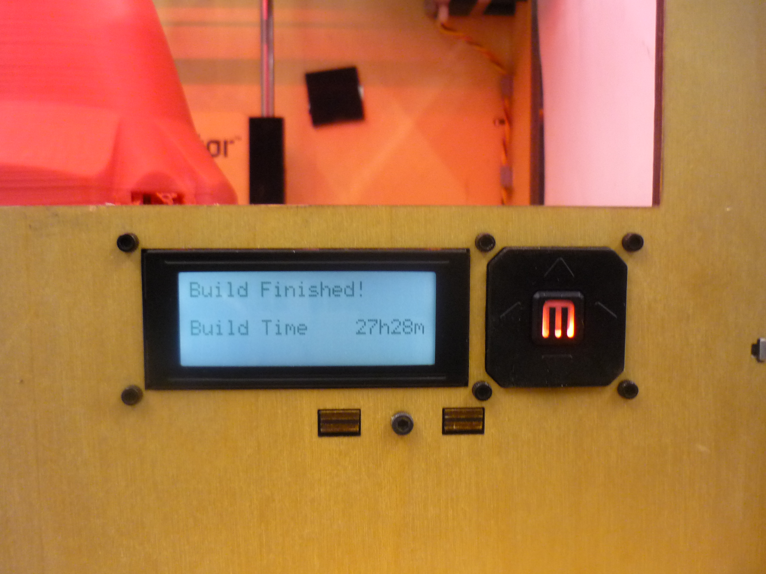
| The
quirk with large prints: THEY TAKE A WHILE. At the time, the 3d printer robot was down for repairs, so I was fortunate enough to use the fantastic replicator over in Charles Guan's WUNDERBAR LAB. The build time was a full 27 hours for the rear nosecone assembly. Poor makerbot! This was a full ABS part, with a 30% fill ratio. It occupied the full build platform, and came out beautiful. |
 |
 |
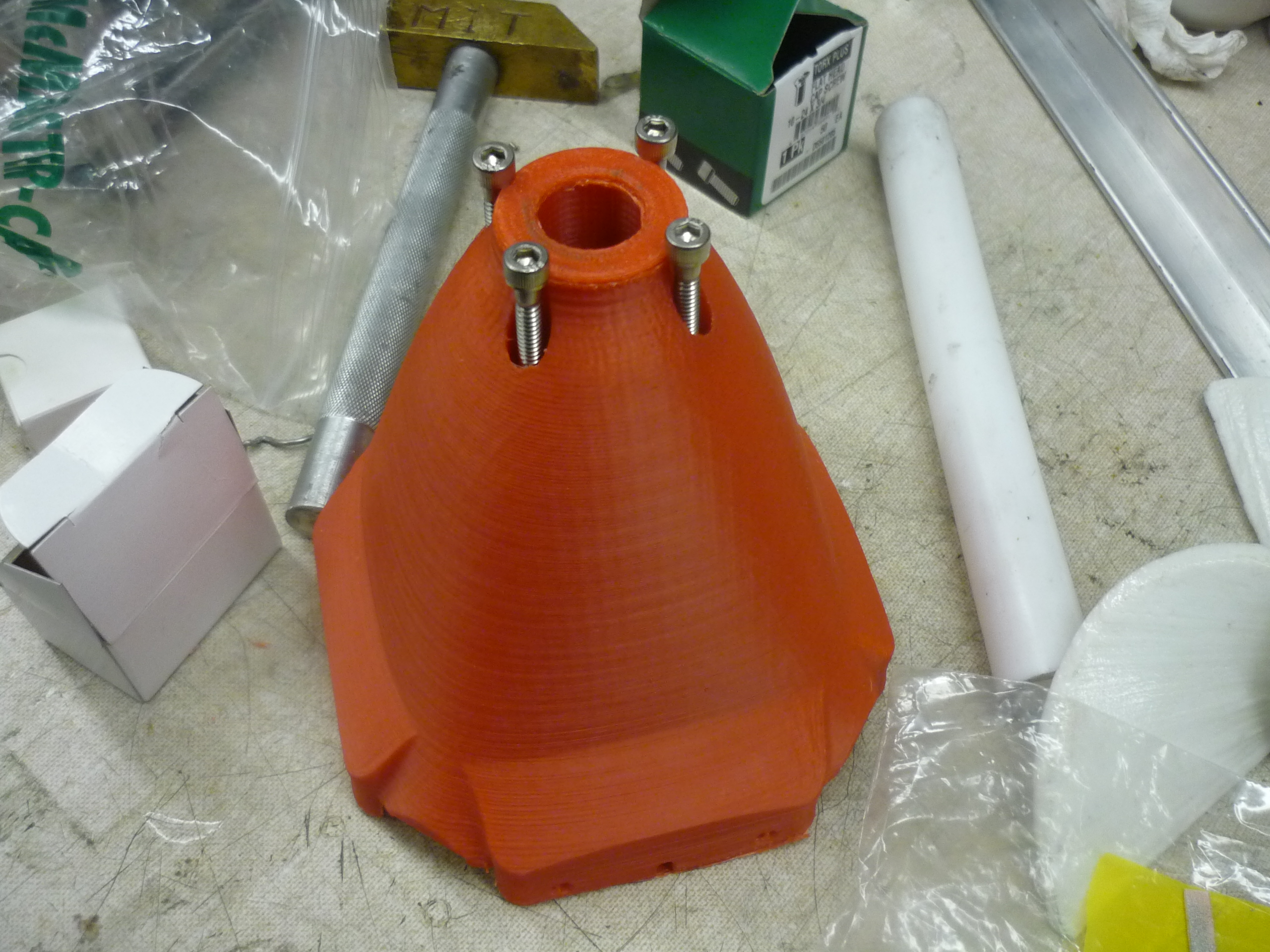
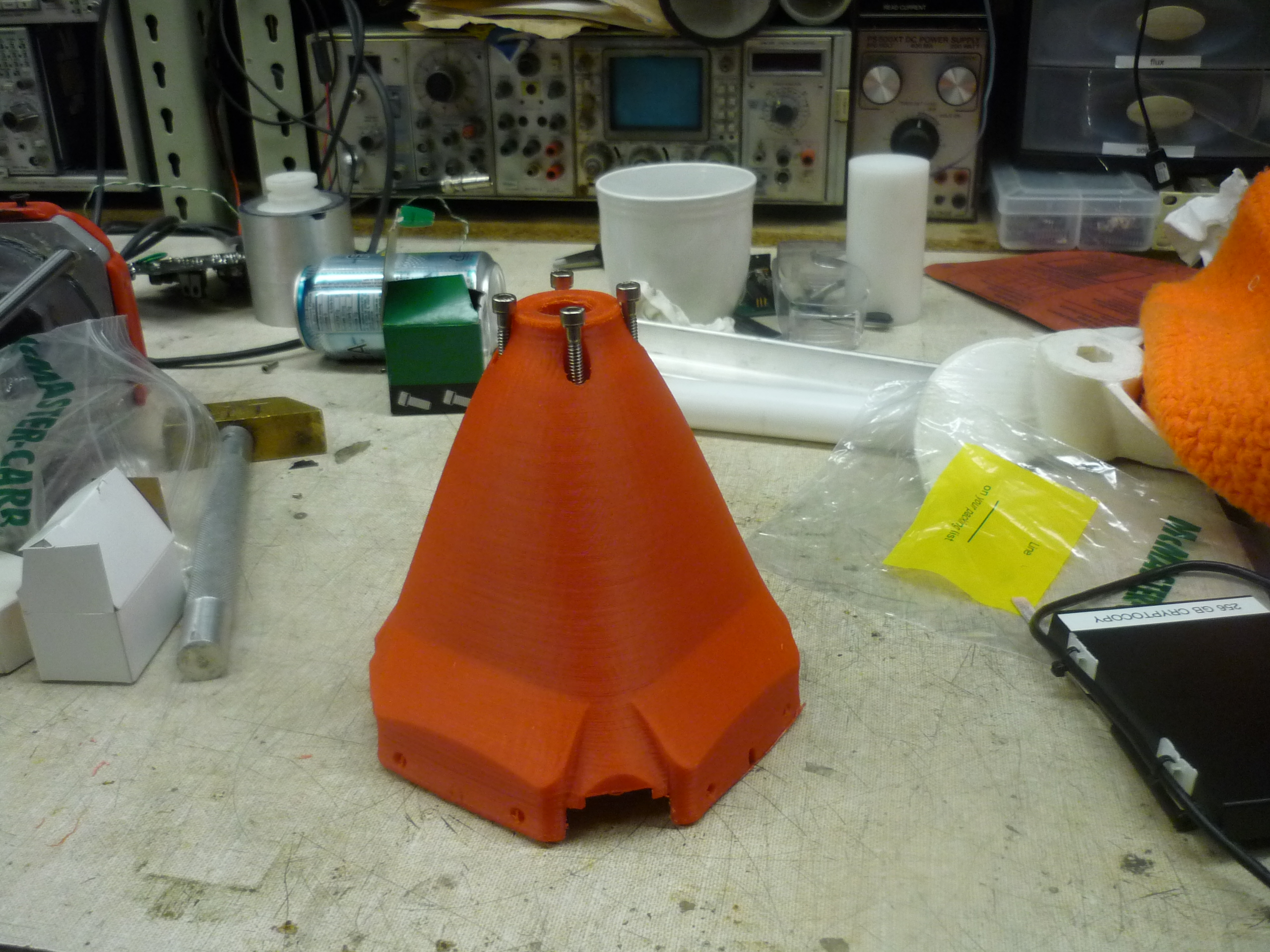
| The
cowling ITS PRINTED AND BEAUTIFUL, now to add some hardware and internal mechanical parts! The cowling itself holds an internal shaft bearing, preventing prop-wobble as it is a full 8" away from the motor mount. |
 |
 |
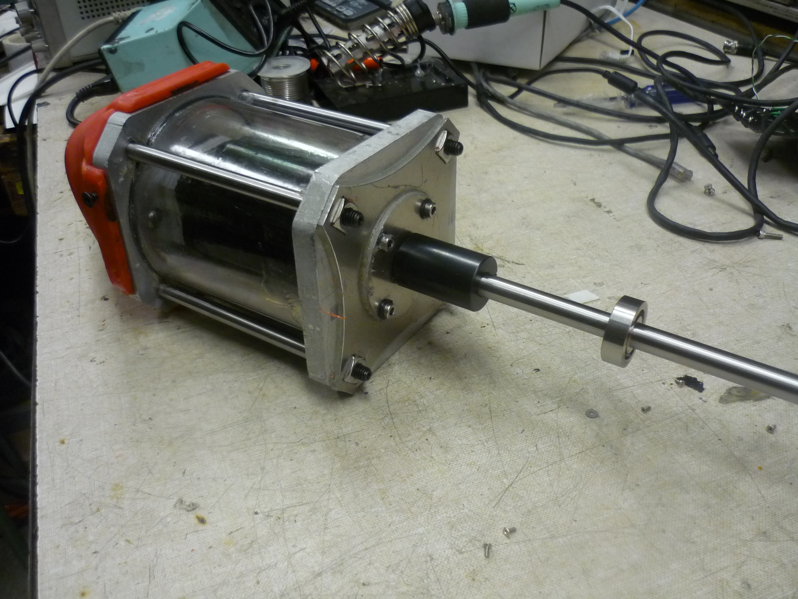
| Adding
the extension and adapter The motor exits with a 12mm shaft, and as this is fairly short for throwing a propeller onto, a coupling and extension bar is added on to the rear cowling assembly. The bearing's purpose is shown below. |
 |
 |
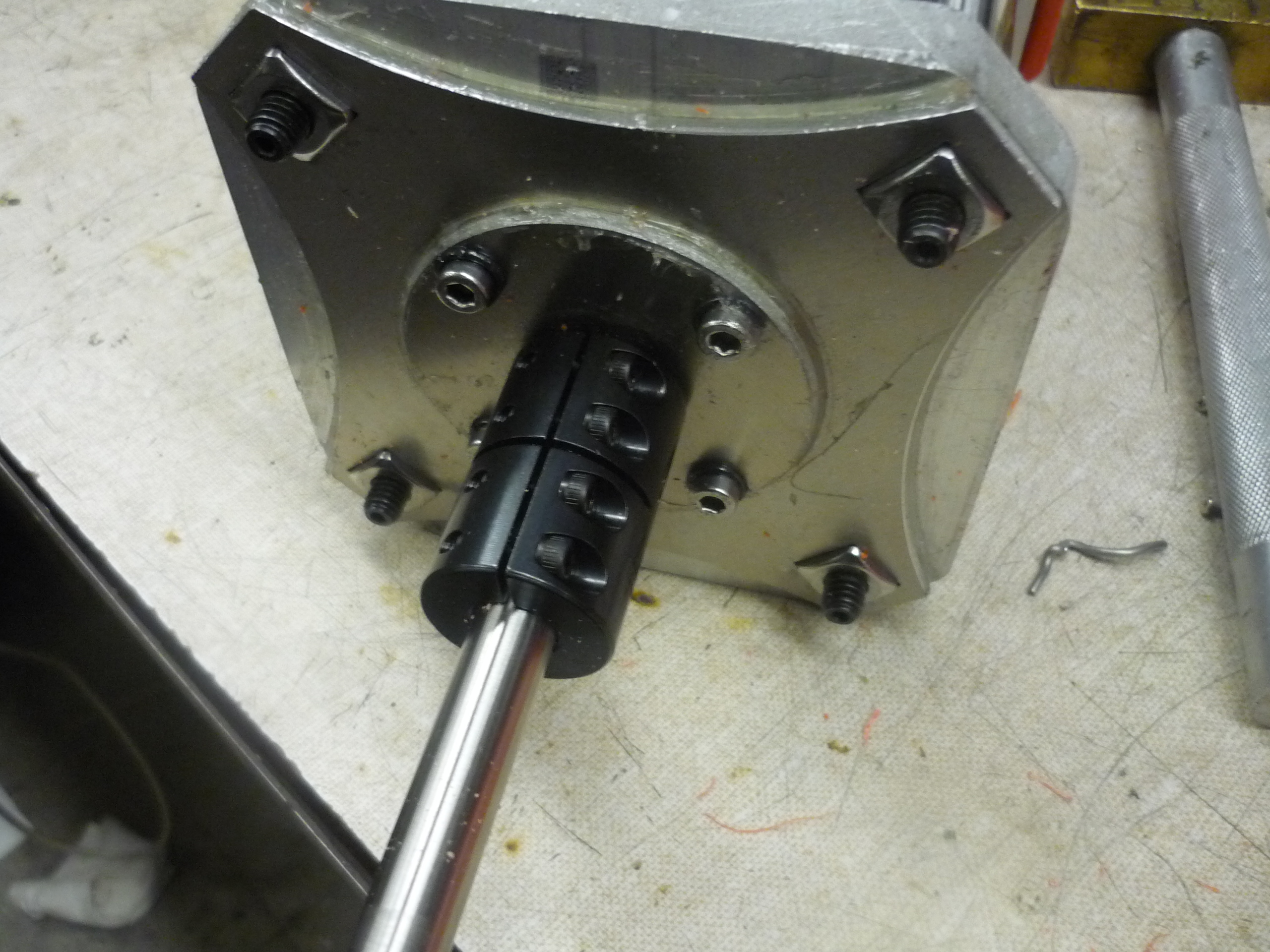
| The
inside of the rear cowling The bearing holster is shown at the far bottom of the inside of the rear cowling. The four surrounding bolt holes pass through and connect to the captive plate that holds the bearing in place. |
 |
 |
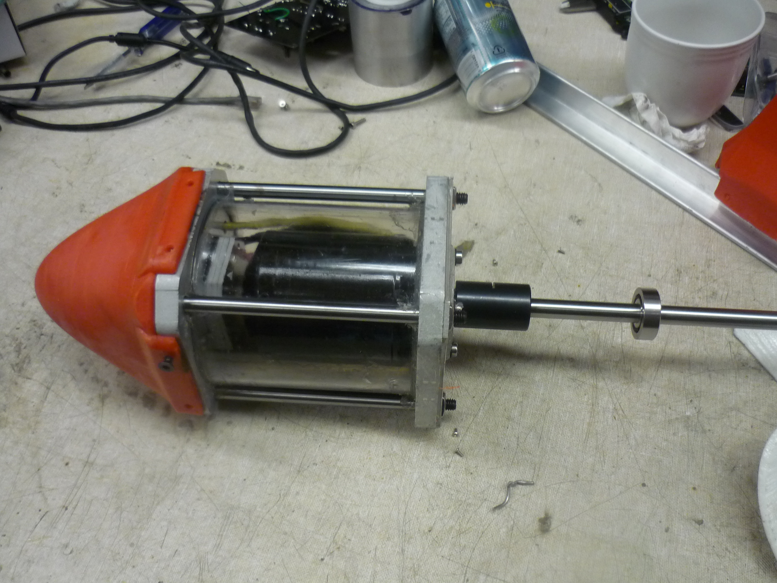
| Rear
Bearing and holster With the self-digging-in screws in place, and sliding the output shaft into the bearing assembly. |
 |
 |
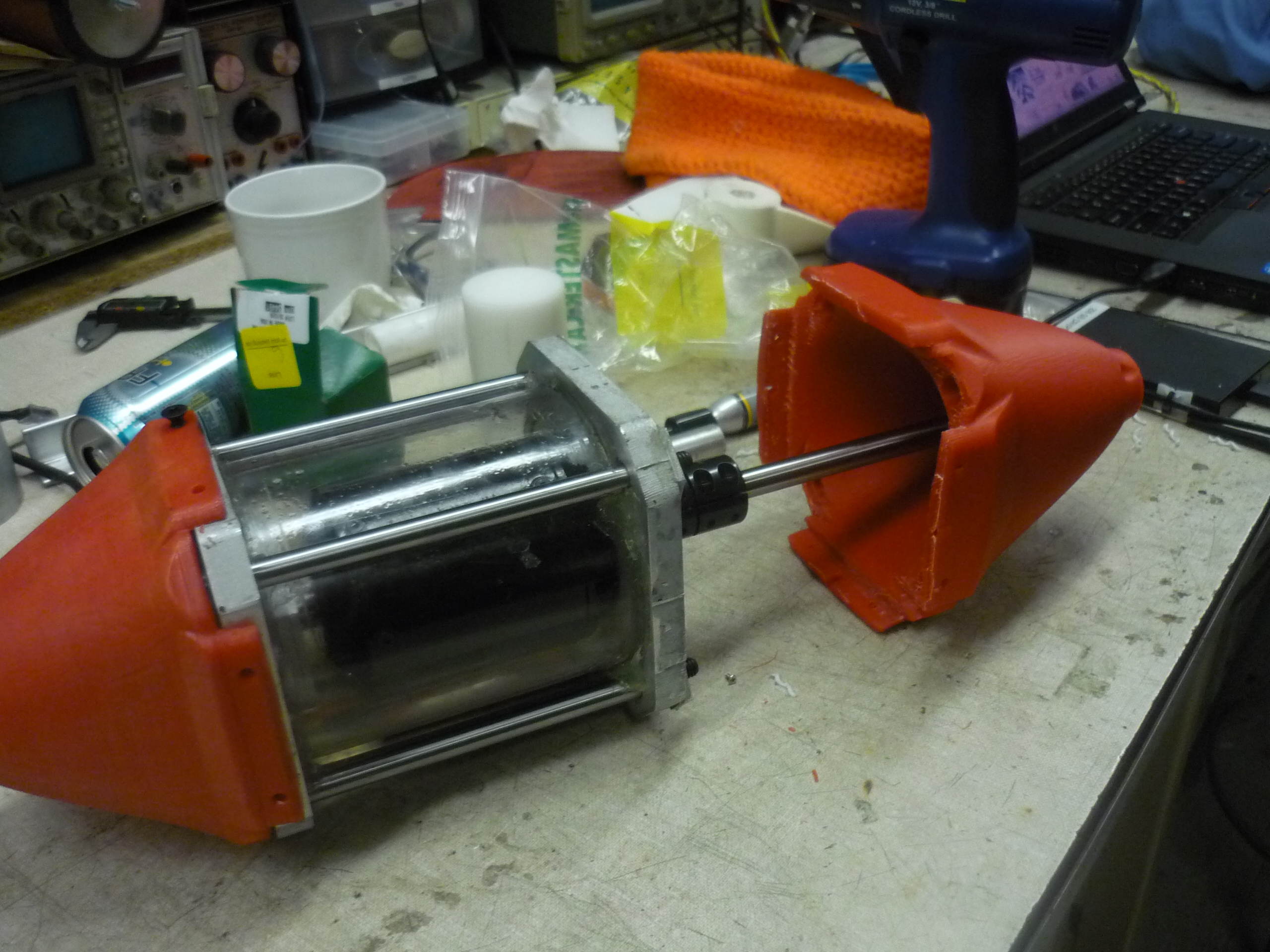
| Sliding
everything together Checking alignment and making sure everything clears. |
 |
 |
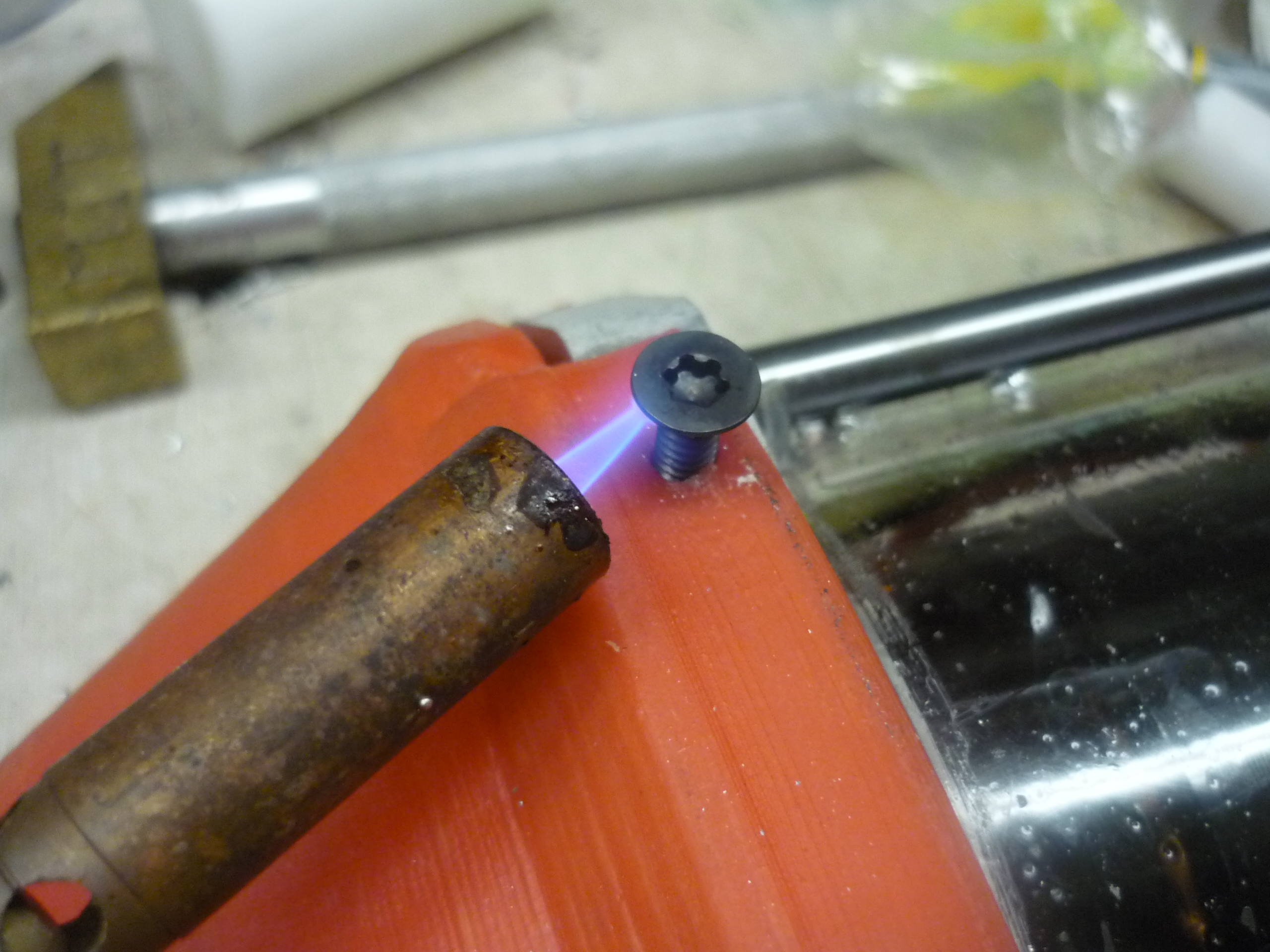
| Torchy
mc-torch bolt using a propane torch, set as low as possible, I heated the torx screws, then rapidly screwed them in place. This formed a tapered fillet and melted the bolt to the part. It came out looking excellent. |
 |
 |
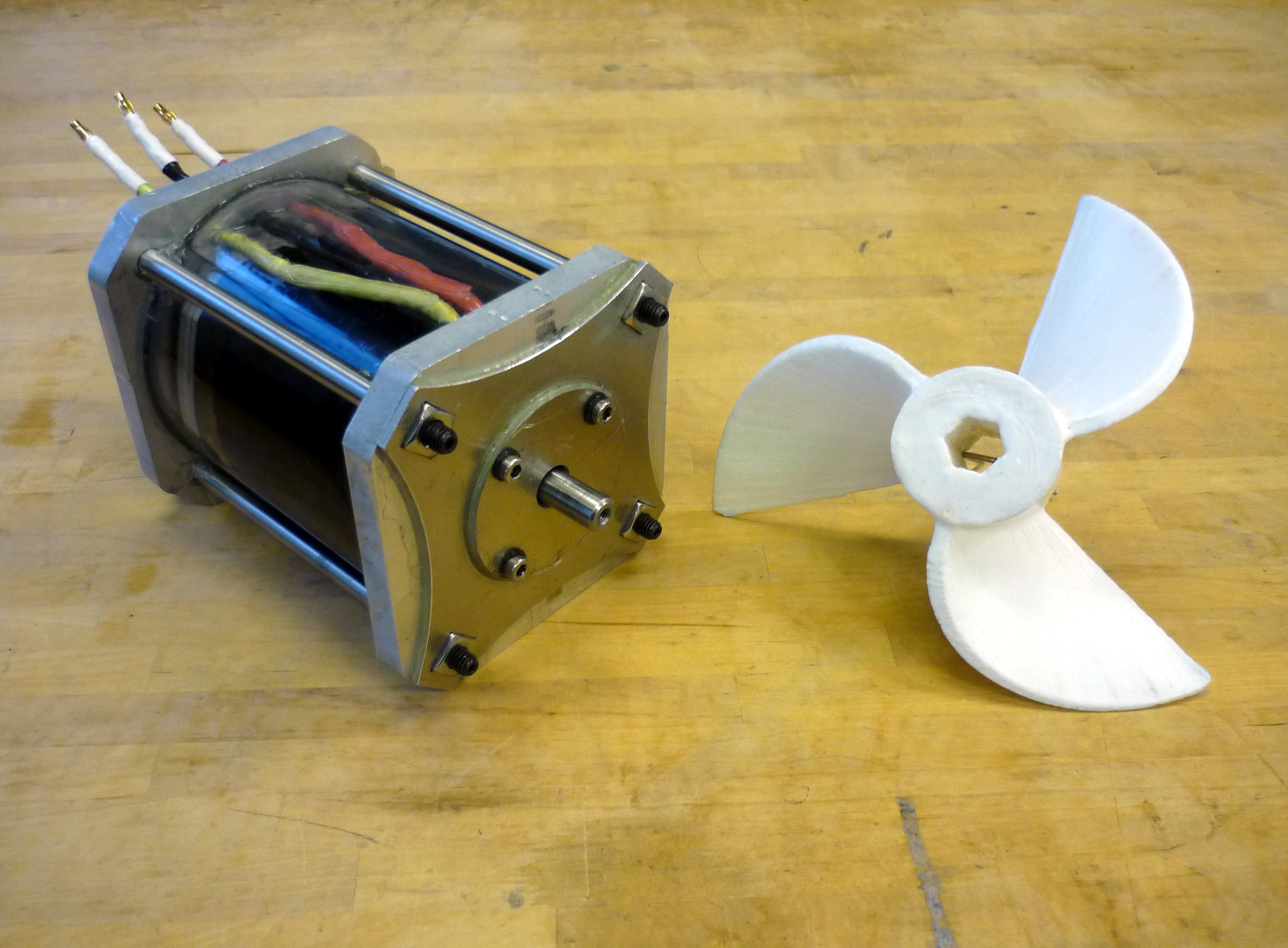
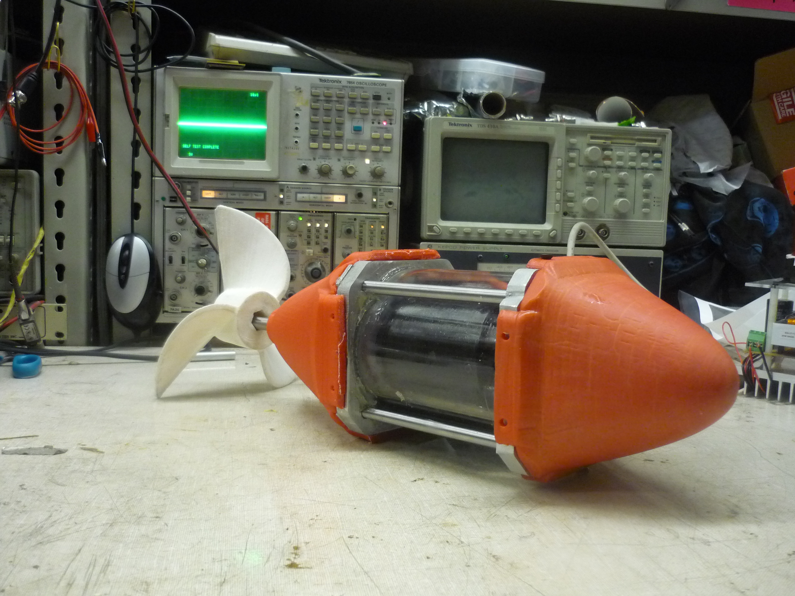
| WEAPONS Ok its no chain sword, but it sure looks nefarious. Shown is the thruster with the 3d printed propeller, printed by the home-robot-printer. |
 |
 |
| Pre
Epoxy Sanding With the comlete print, the parts were sanded, then wet-sanded (to eliminate dust). Shown (right) are the sanded nosecone and rear cowling. After sanding, i applied a layer of 2 part epoxy to provide a heavy outer coating for the part, absorbing energy from impacts and preventing the plastic from shattering too easily. I tested mixing acetone in with the 2 part epoxy and it resulted in a bit of cracking, but seems to hold up well to impacts. |
 |
 |
| Epoxy
and Paint After a fair amount of drying, from the suggestion of the ever-awesome Adam, i used krylon plastic paint, coated the parts, and 'baked them' next to some bitcoin mining rigs. The paint seemed to bond well to the bare abs part, but not as well to the epoxy'd nosecone. |
 |
 |
| So
Fancy With all the parts mocked up i layed the thruster on the cleaned non-ferric stained lab bench for a beauty shot. |
 |
 |
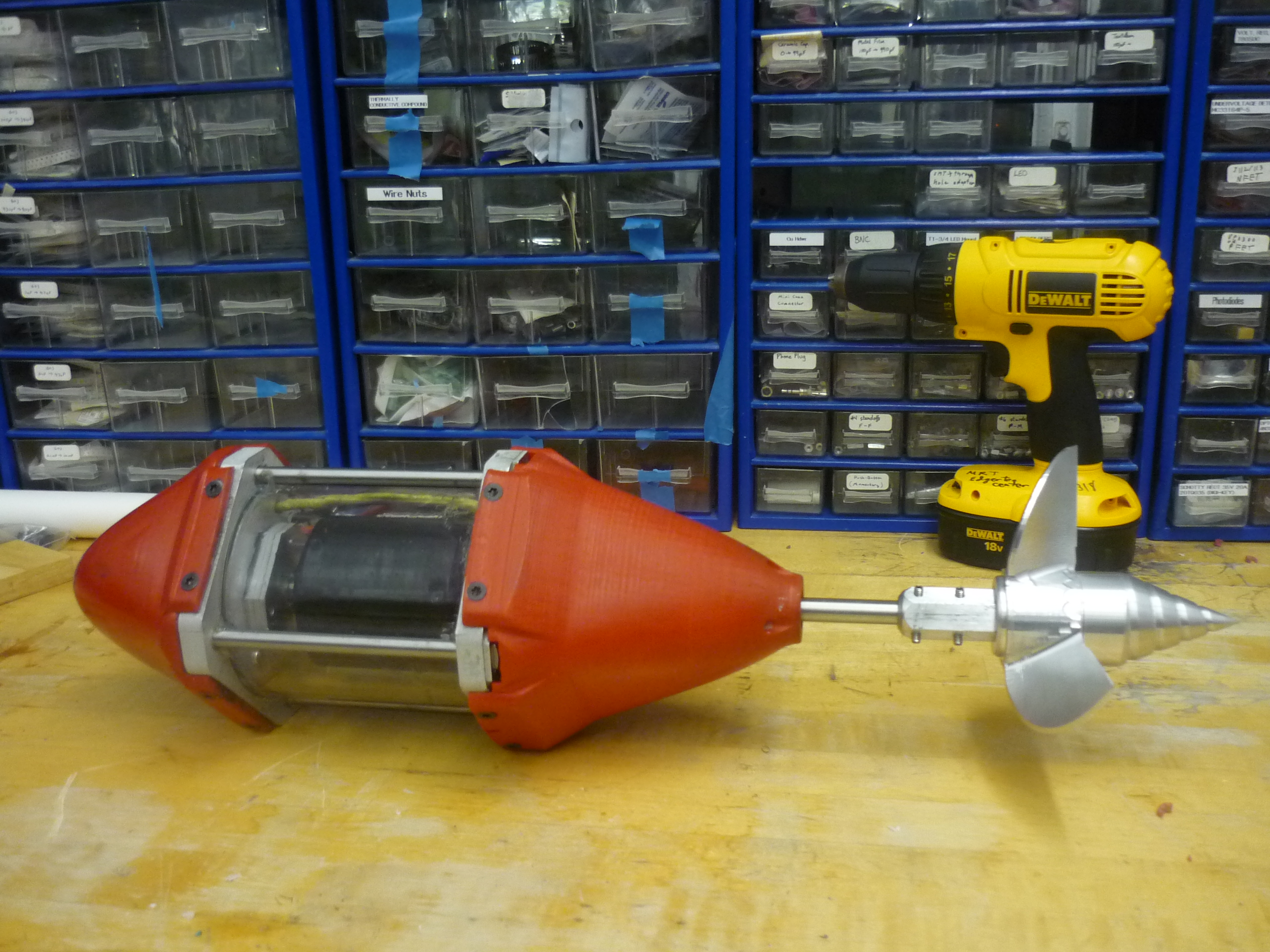
| Mounting
Bracket To test the thruster, I needed a quick mounting assembly. I tapped four 1/4-20 screws into the front and rear plat and made a 2 bar extension to allow for outdoor testing. A Bayley is used for scale (far right). |
 |
 |
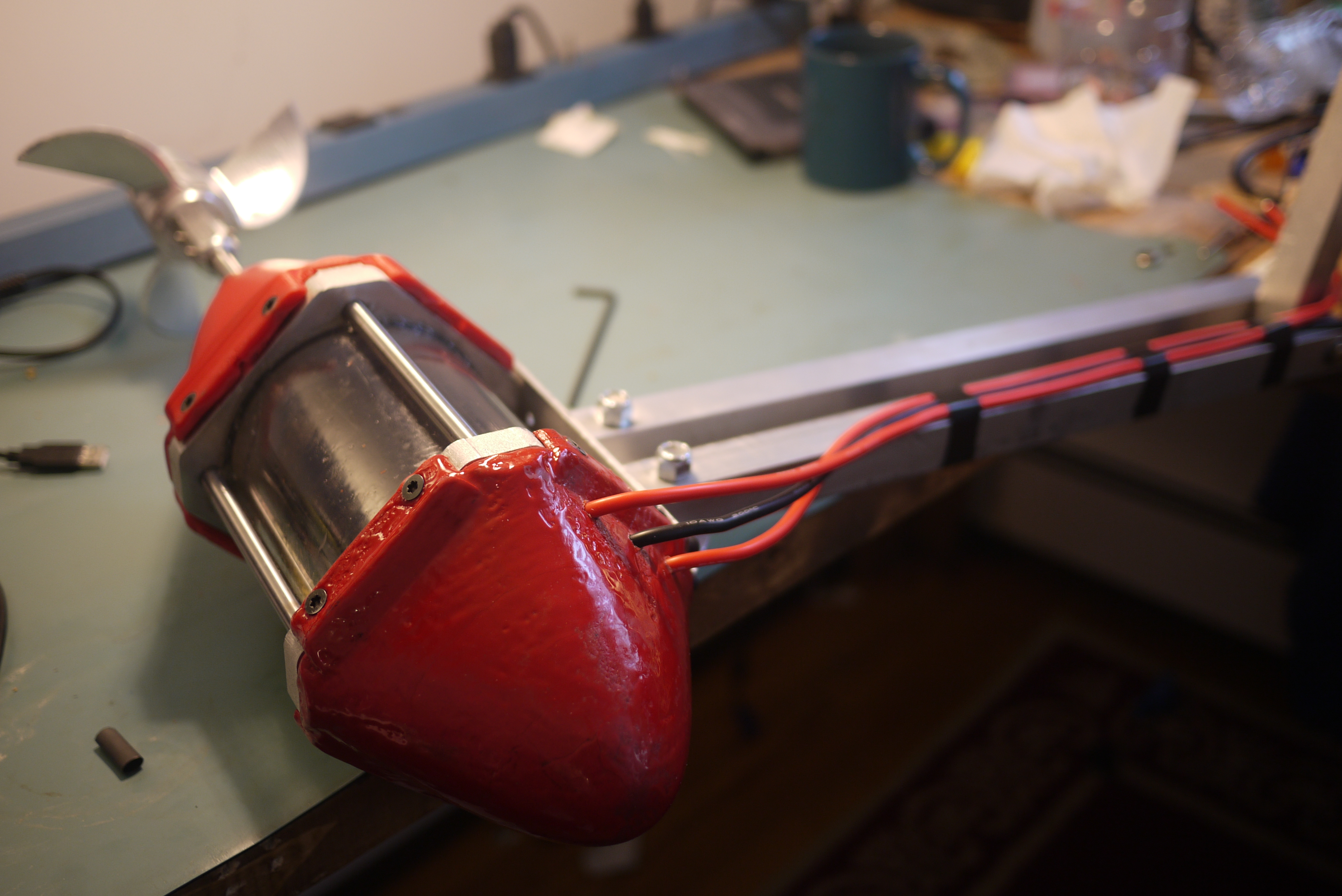
| Feeding
through the cabling The bulkhead connectors worked great for getting the wires out from the inner motor, next i used bullet connectors and 10 gage super-flexi wire to feed the three-phase feed up and out from the motor. |
 |
 |
| Thruster
wiring on the apartment-bench |
 |
 |
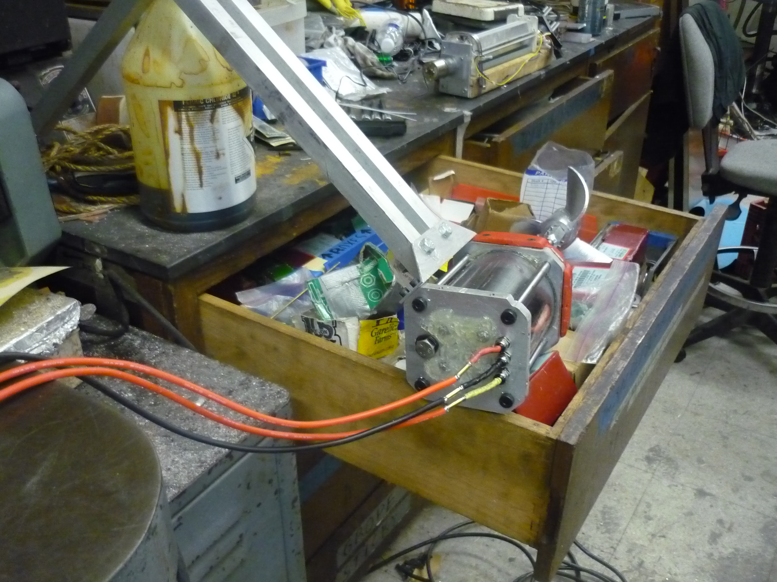
| Romantic
Dinner Table Testing After finishing the cabling, i connected it to the only clear surface, a butchers-block kitchen table, where a ~100kw three phase siemens motor is the second seat. The motor assembly is clamped to the scooter (providing the 3phase feed) which is then clamped to the table. Clamps on Clamps. |
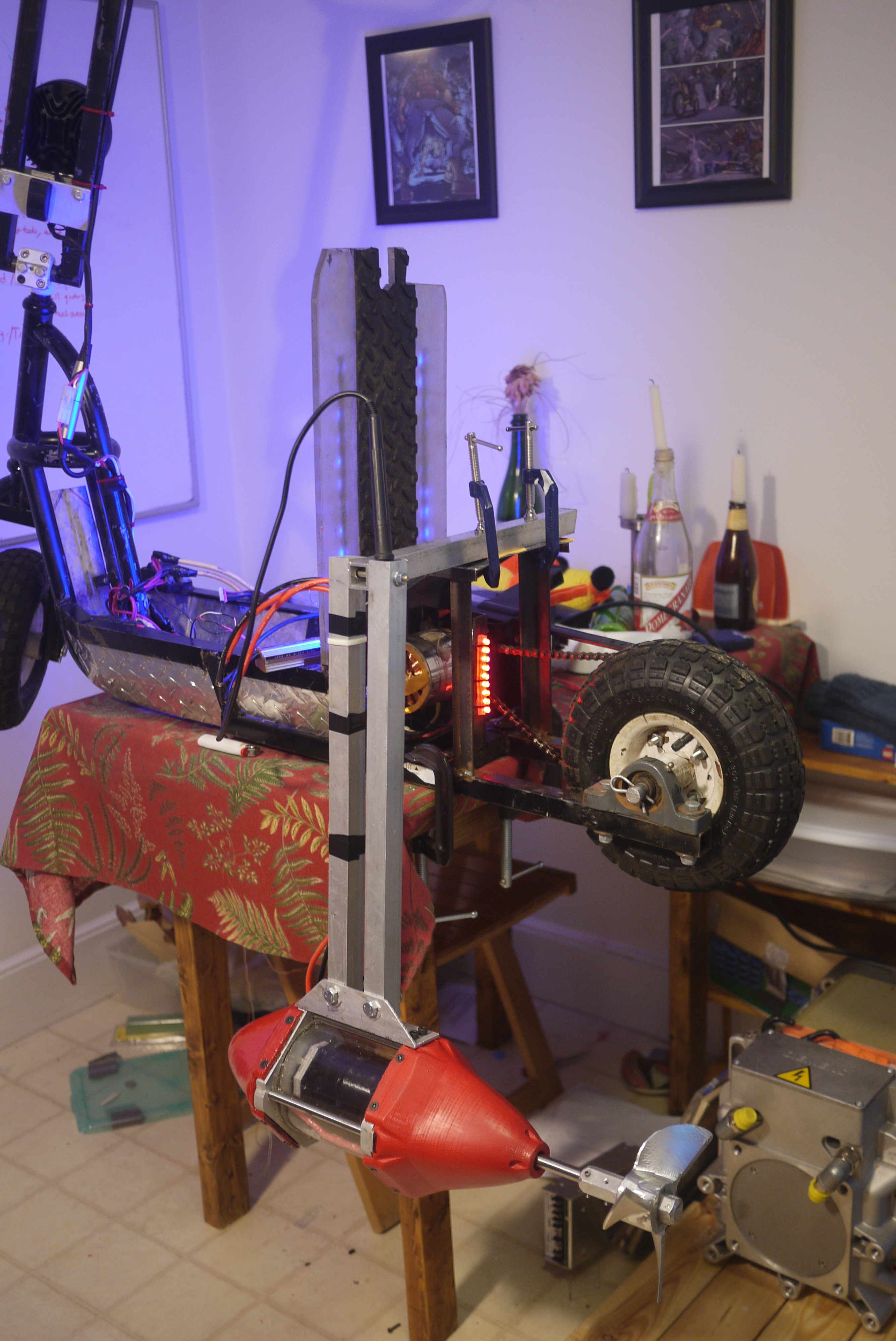 |
| Dinner Table Static Spoolup |
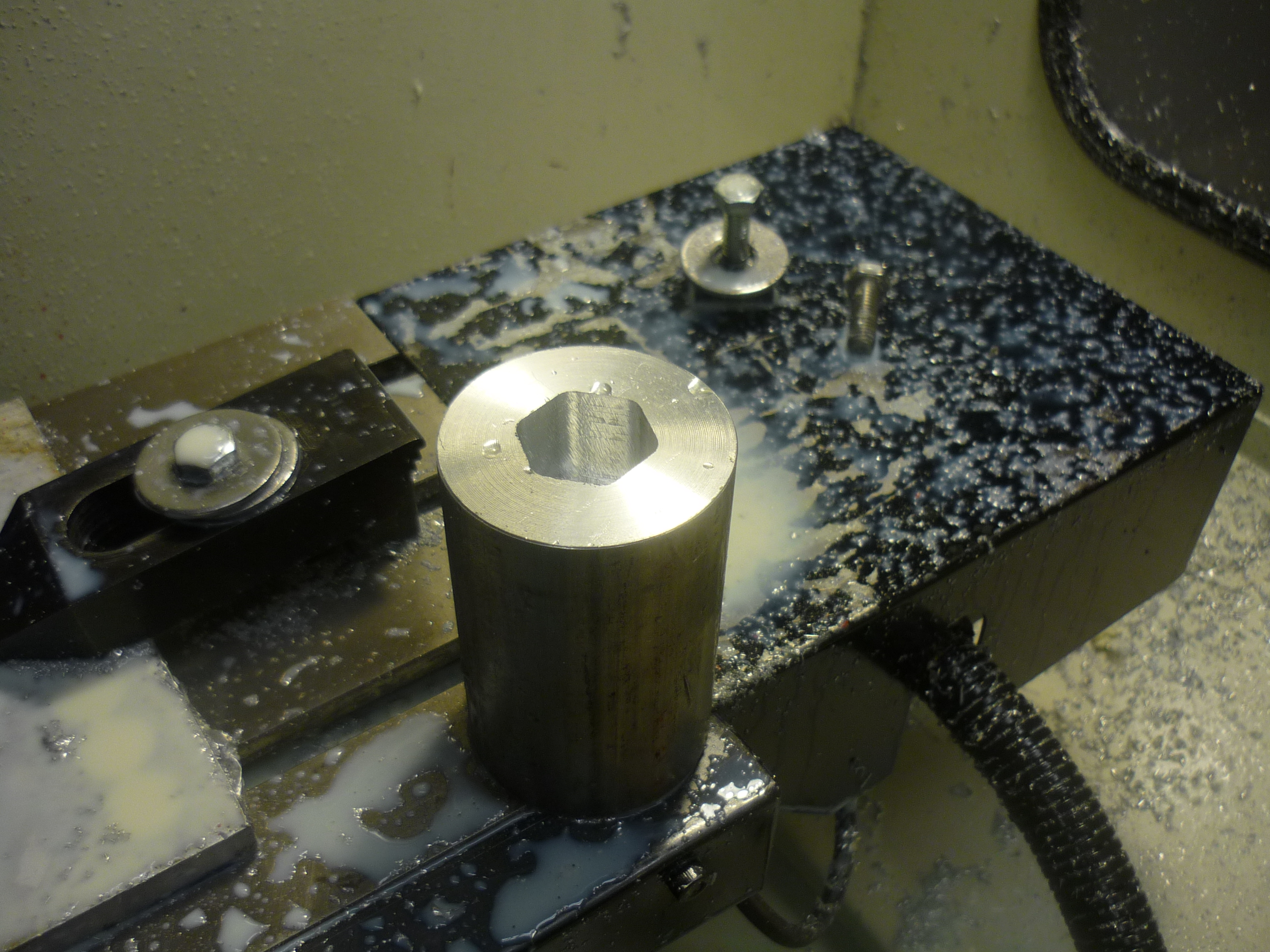
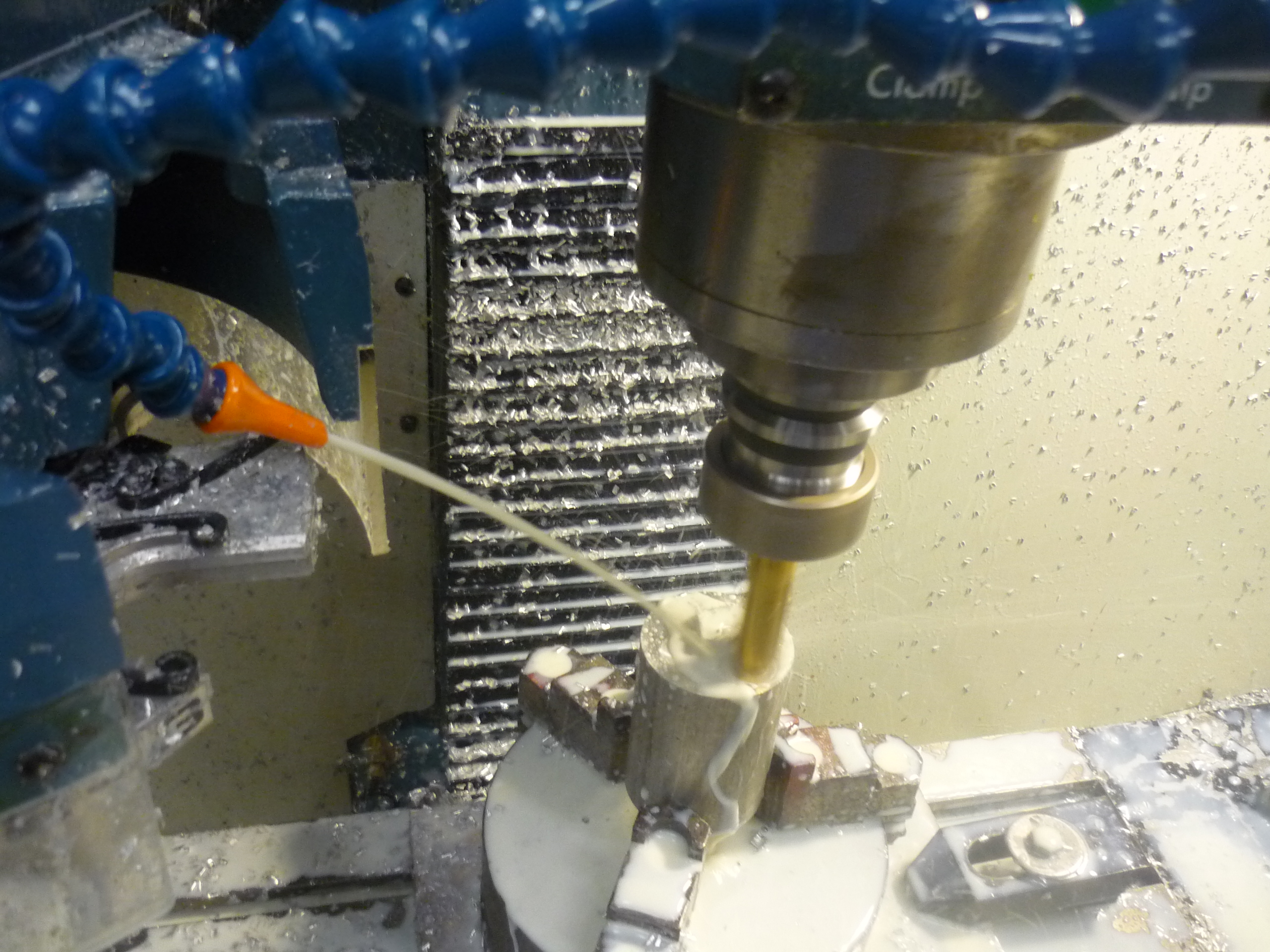
| Machining The Turbulence Destruct-er-ator | ||
| The back side of the propeller was actually not very hydrodynamic. I was concerned that hydro flow would form a pile of bubbles as it swooshed by, so i came up with an odd endcap which should hopefully guide the water away without cavitation. I used an 1/8" 4" long end mill (ebay) and was able to slowly cnc out the hexagonal shaft collar fit. Note I completed this bottom hexagonal cut first. | 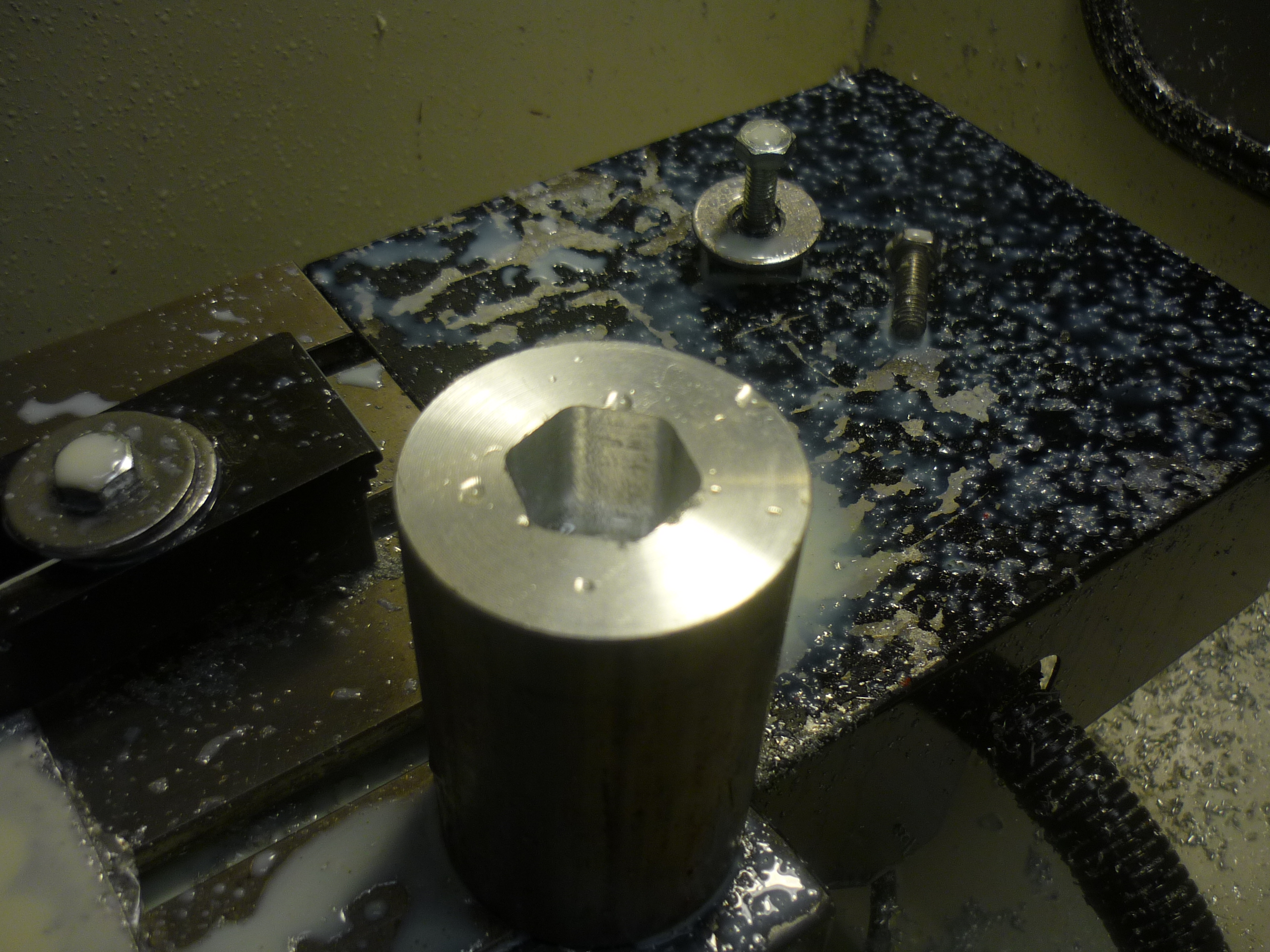 |
 |
| Beginning
the topside machining. Using the lathe-chuck mount, and the same zero location from the previous job i flipped the part and 2-part machined away to get the sharpened spiral. |
 |
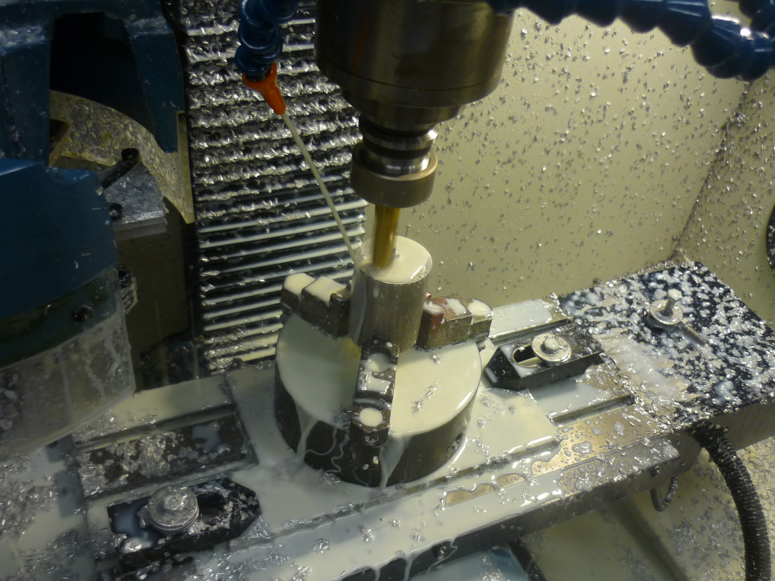 |
| Big
Cutting Using a 5/8ths end mil, a majority of the cylinder's mass was removed, in a coarse cutting action. Unfortunately I did not have a ball end mill handy so i completed the remainder of the screw with the 5/8ths end mill with incredibly small pass heights. |
 |
 |
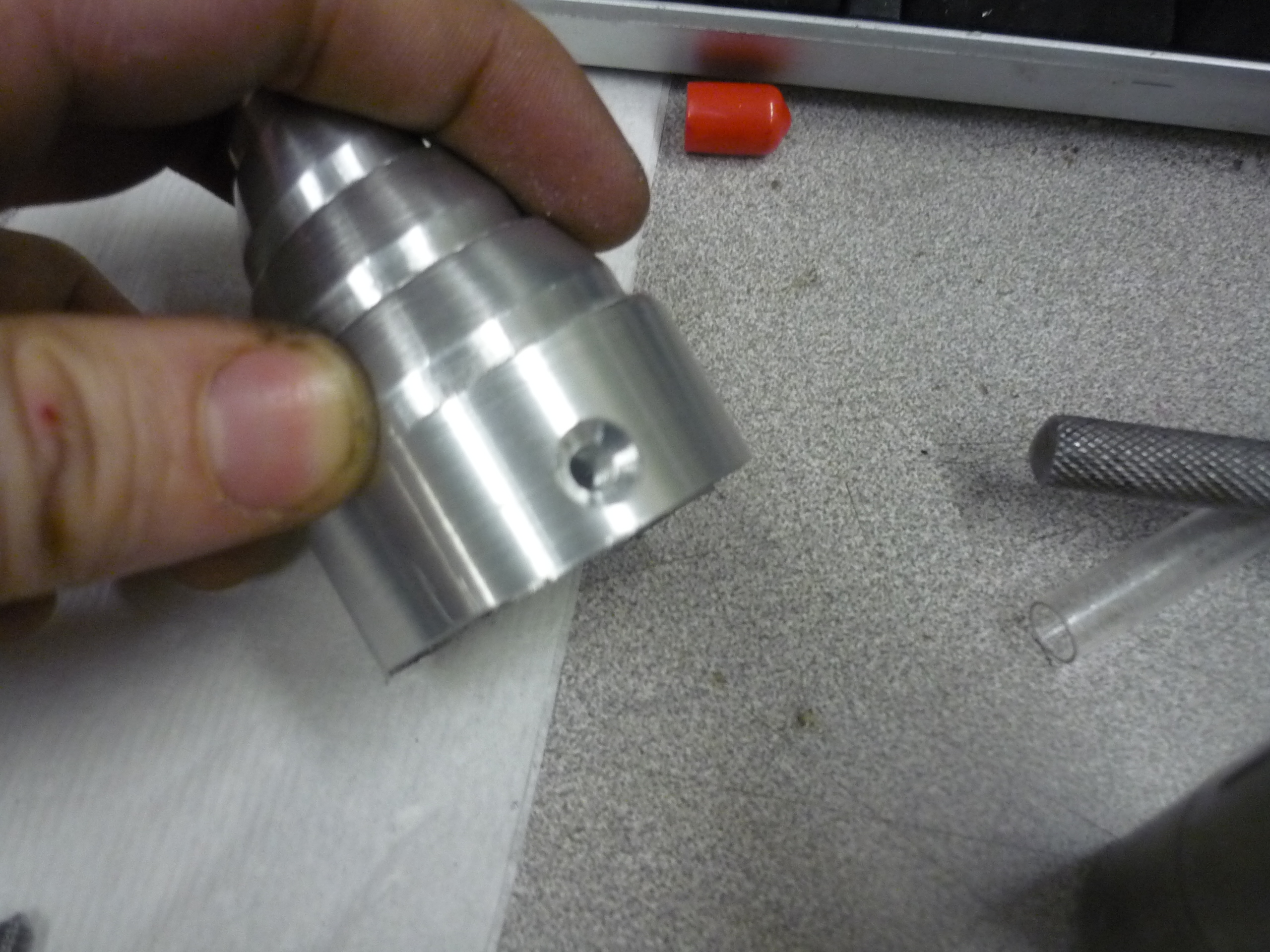
| Tapping
and counter-boring A 10-24 Tap is used to thread the cone to the hexagonal shaft. |
 |
 |
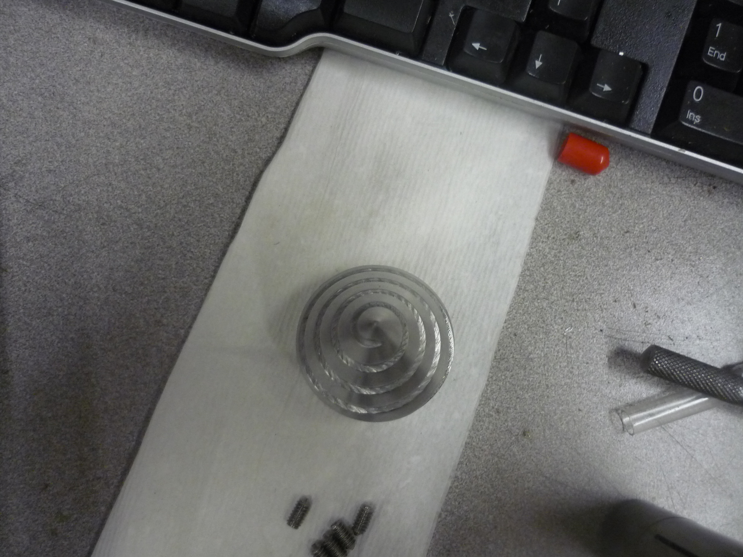
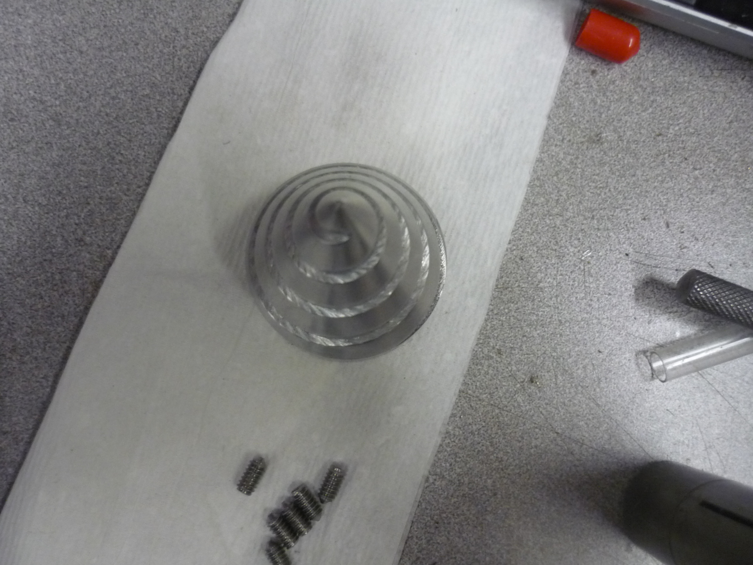
| A
top view of the spiral Note this was cleaned with some steel wool while mounted on a lathe to archive the polished finish shown. |
 |
 |
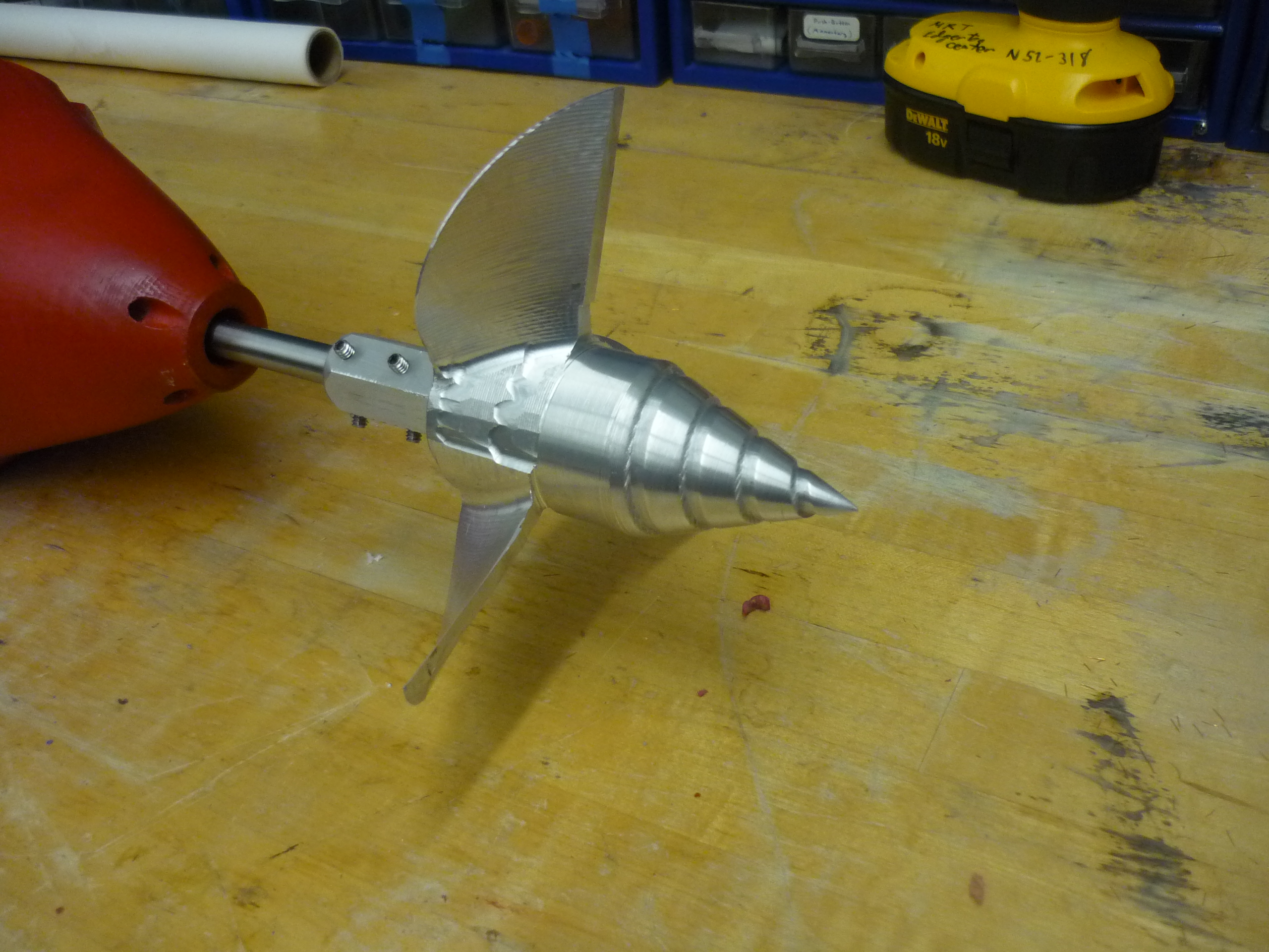
| Doesnt
that look.... Dane-gerous Walking around campus with a small torpedo does garner some interesting looks from passerbys. Where'd the aluminum propeller come from? THATS another story.. Stay tuned. |
 |
 |
PART III: Bracing and Canoe quick-release mount
| Removable thrusters? |
 |
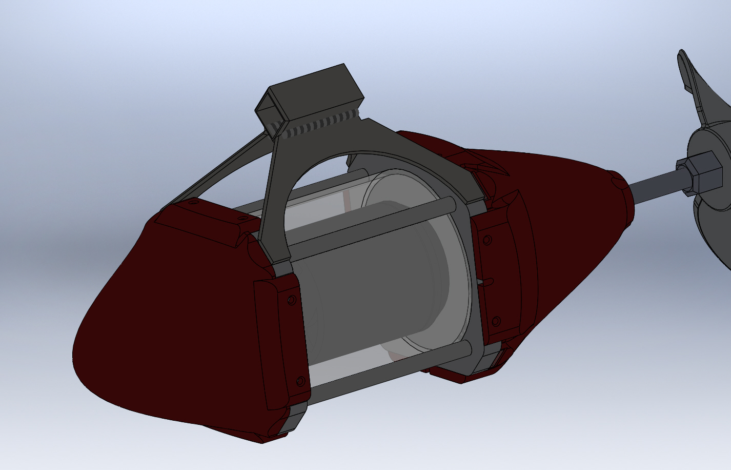
| Mounting The Monster | ||
| Ideally the thruster assembly should be quickly removable to aid in diagnosis / speed up assembly-on-the-beach time. I wanted something simple that was fairly hydro-dynamic, so i opted for a square-tube-in-tube setup. Where the assembly would slide onto a rigid holster and either a pin or a locking mechanism would hold it in place. The square tube prevents the motor from rotating on its mount under load. Due to the geometry and wanting to keep lever-arm forces at a minimum on the joining mechanism, a weld is needed connecting the square tube and waterjet mounting plates. |  |
 |
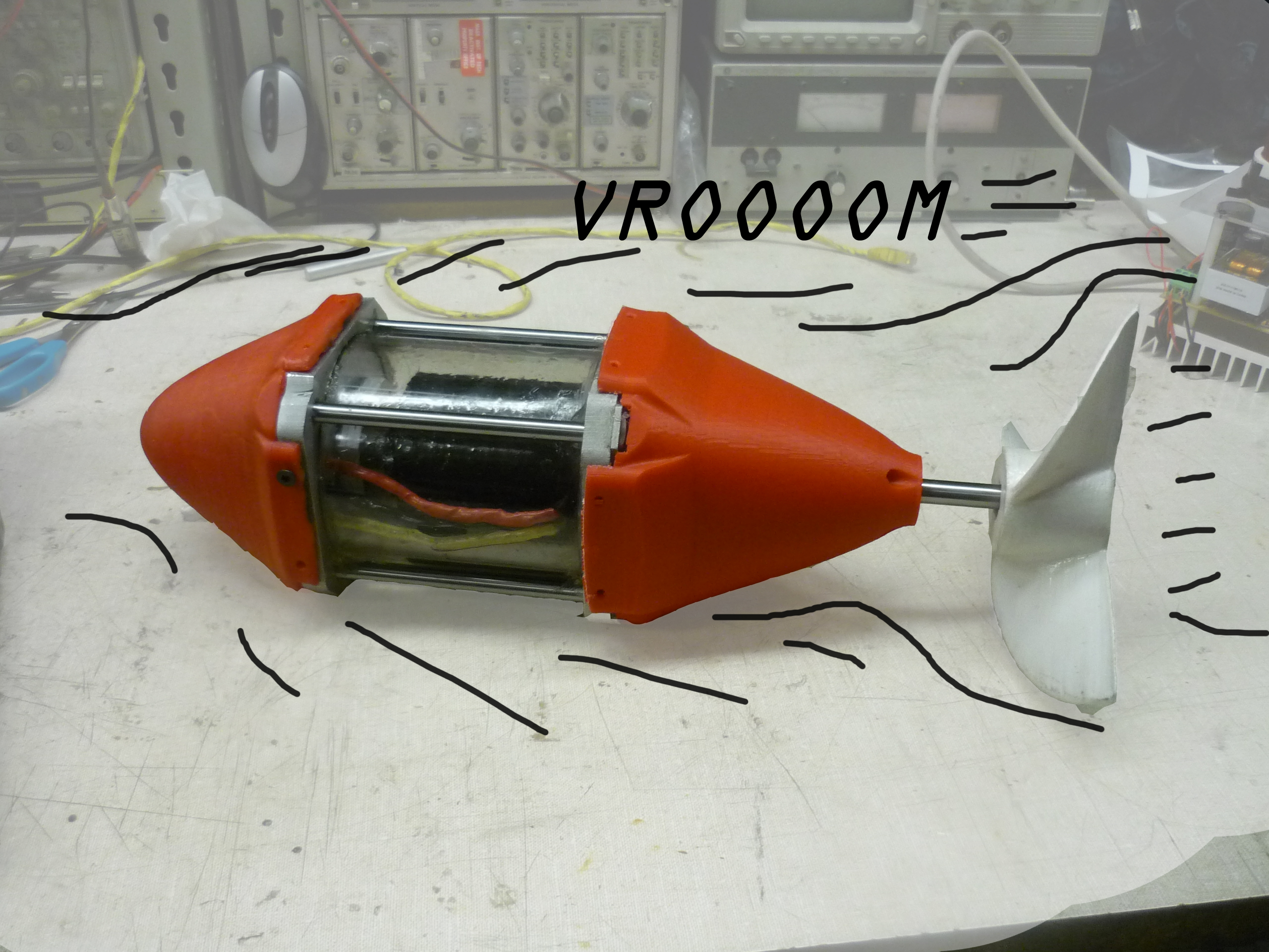
| Canoe-Side
mount The planned mount is a stainless steel hanger that bolts into the plastic part of the canoe project, using a square-tube-in-tube + pin locking mechanism. This constrains motor movement and transfers a majority of the loading into the plastic canoe sections. VROOM. |
 |
 |
| Abuse Testing | ||
| The submersible thruster was tested out in the middle of a resoviour, bumped into rocks and was dropped off of a vehicle roof. The only major signs of duress were the edges of the rear cowling. During one of the impacts the cowling dislodged and sheared the retaining parts of the plastic. I re-bonded them together using 5 minute DEVCON 2 part epoxy. | 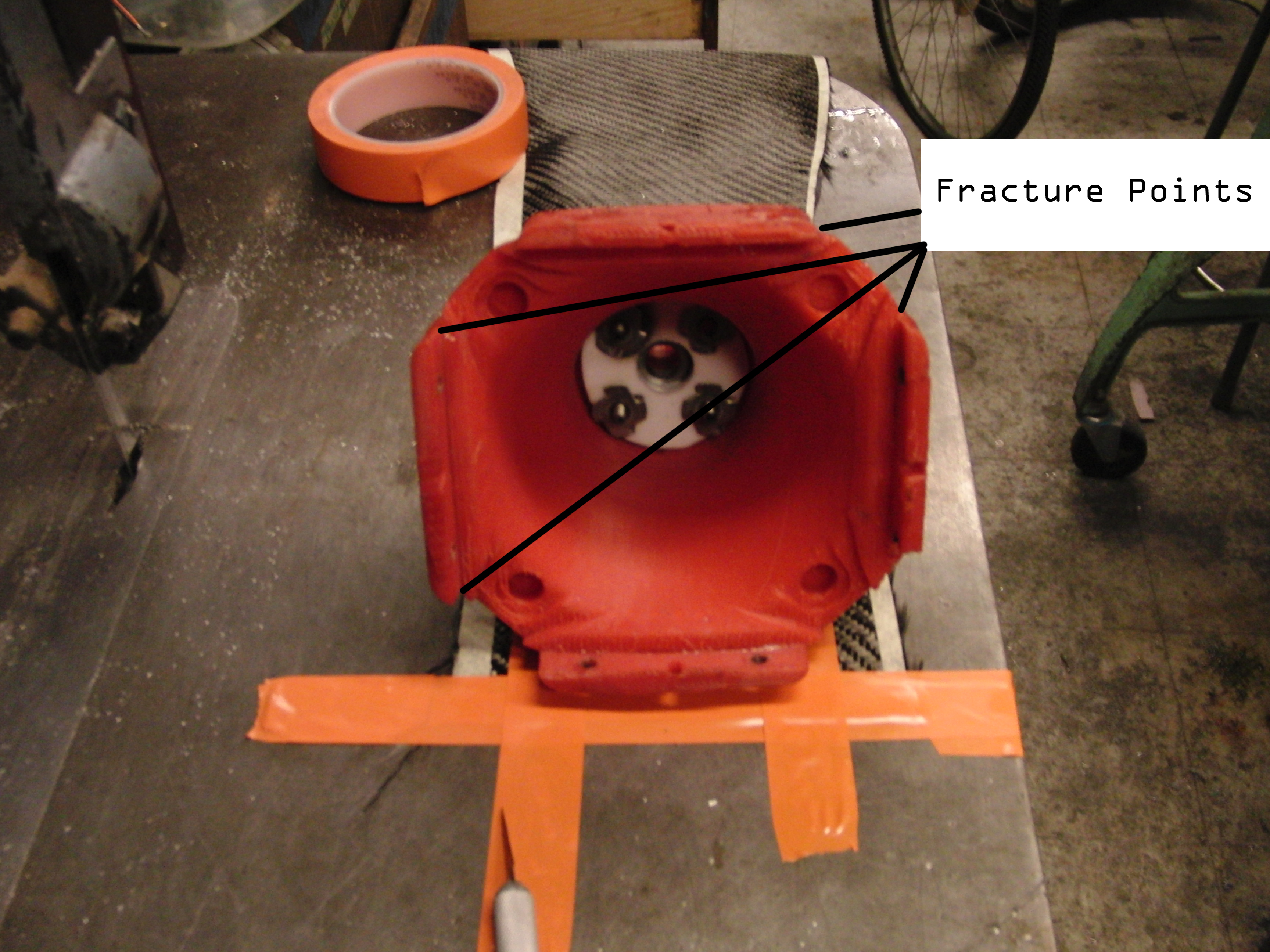 |
 |
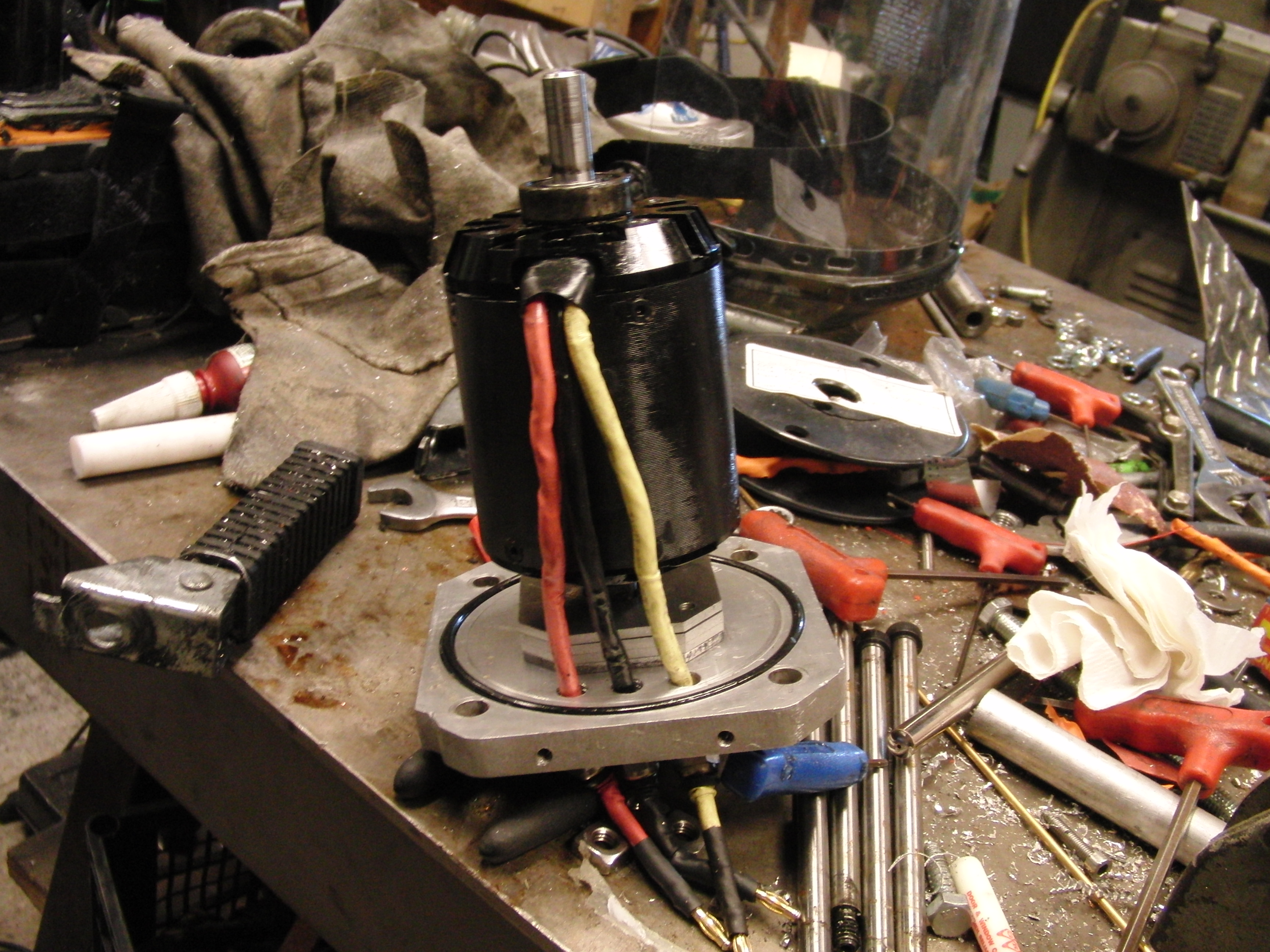
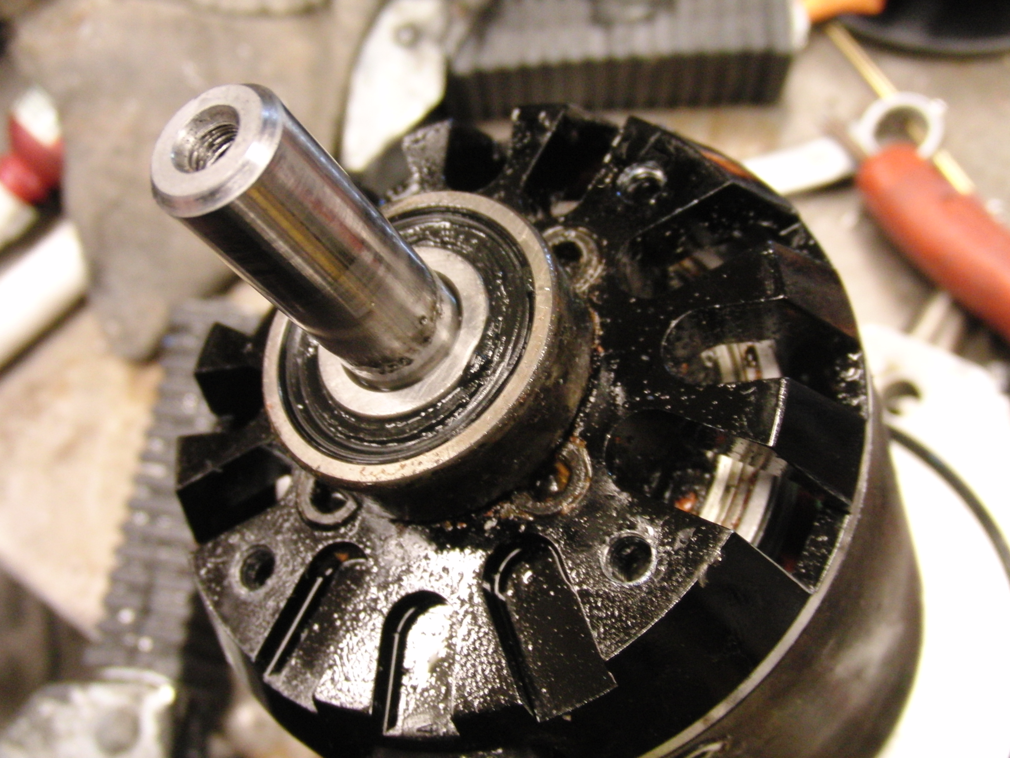
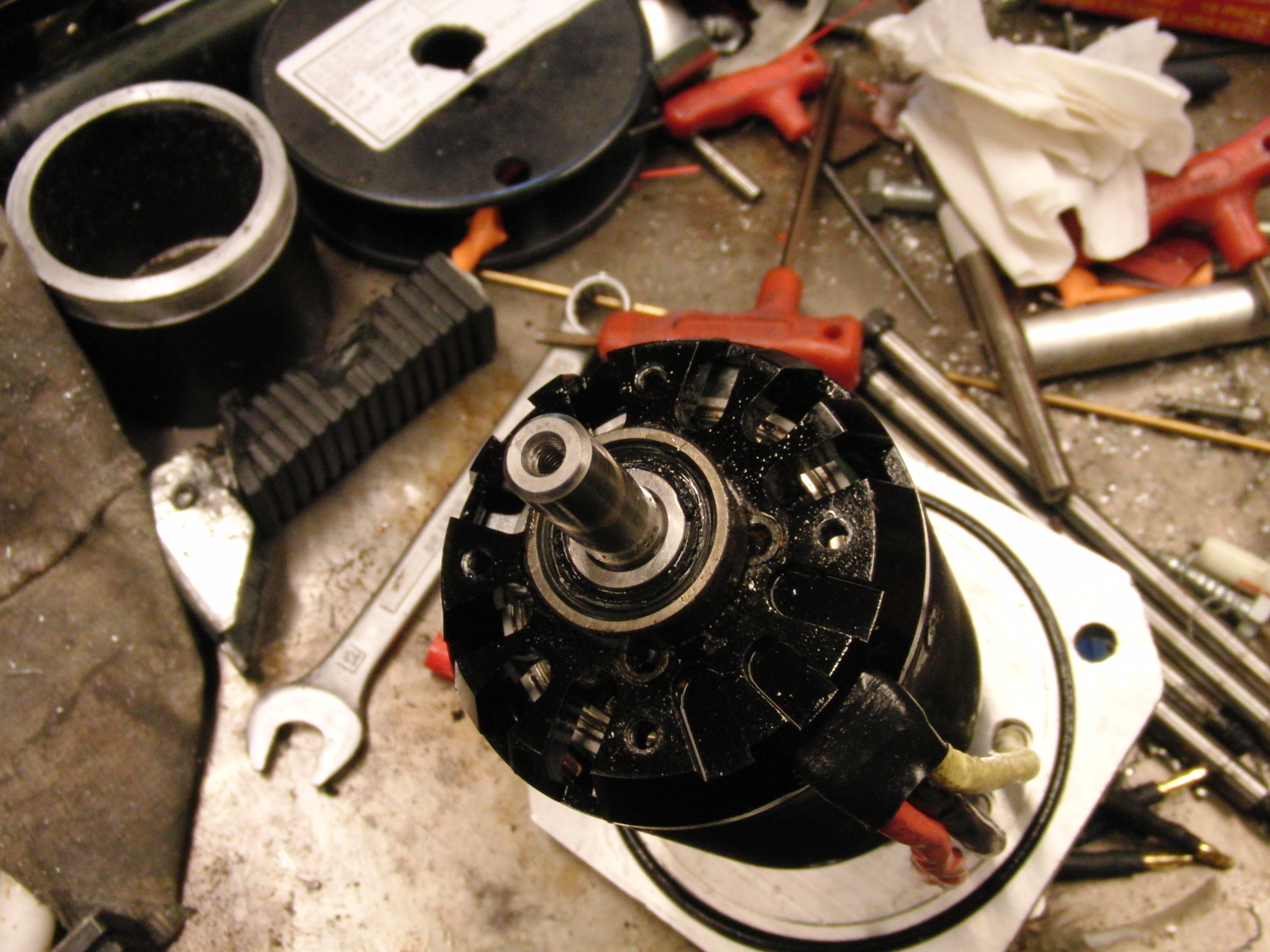
| The
motor itself had some issues. I had drained the mineral oil from the
casing after the last test in the nearby resoviour, and 3 weeks passed.
Leftover oily sludge congealed around the bearing surface and made it
difficult to spin. After a few twists, it was back in working order.
The set screws binding the case to the shaft were also vibrated loose.
I used loctite and set them back in place. |
 |
 |
| The
case seemed to hold up fairly well The polycarbonate tube was definatley murkier, but the seals seemed to hold up fairly well. The o-rings had not danced out of their grooves. |
 |
 |
| Carbon Fiber | ||
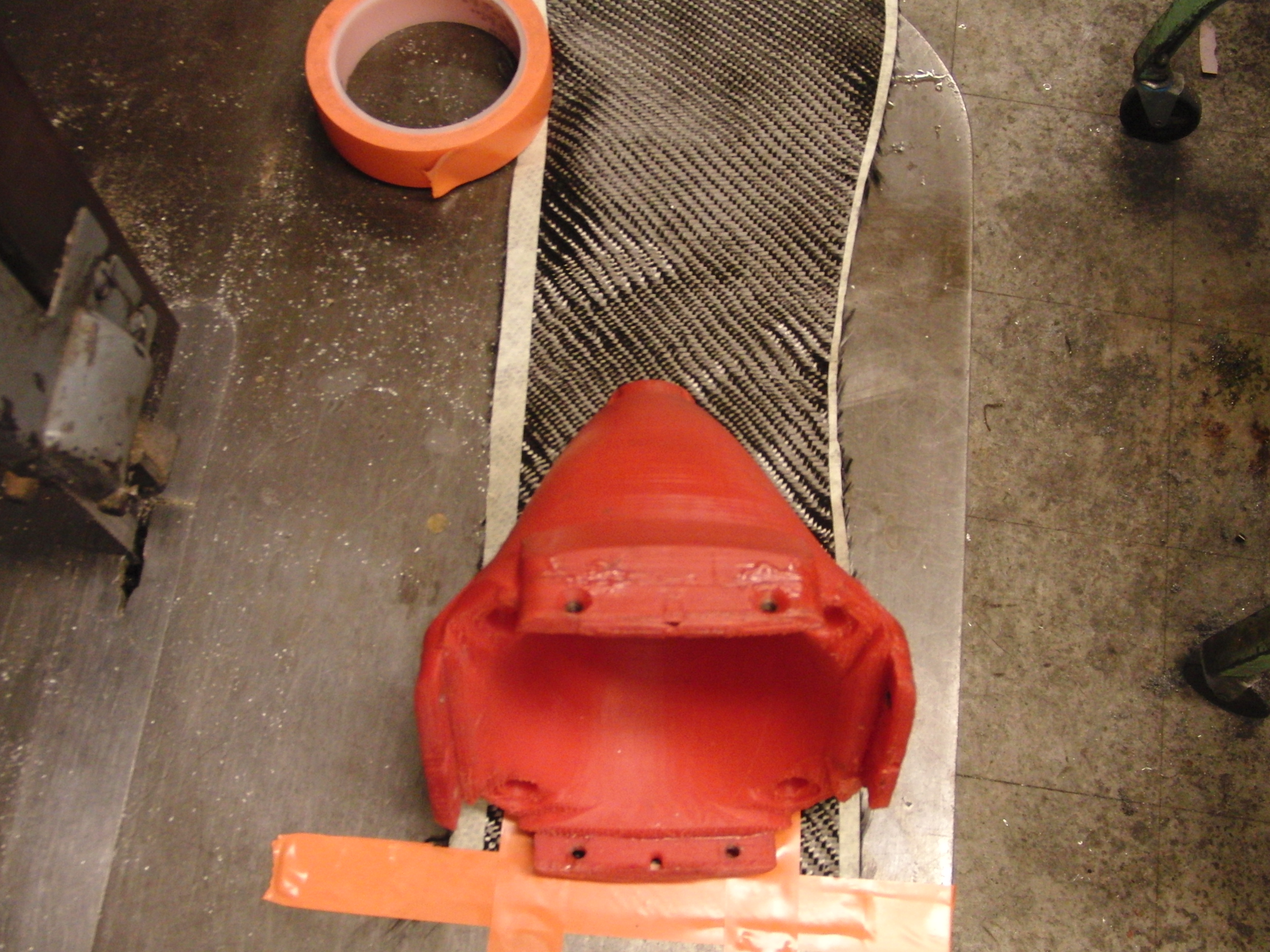
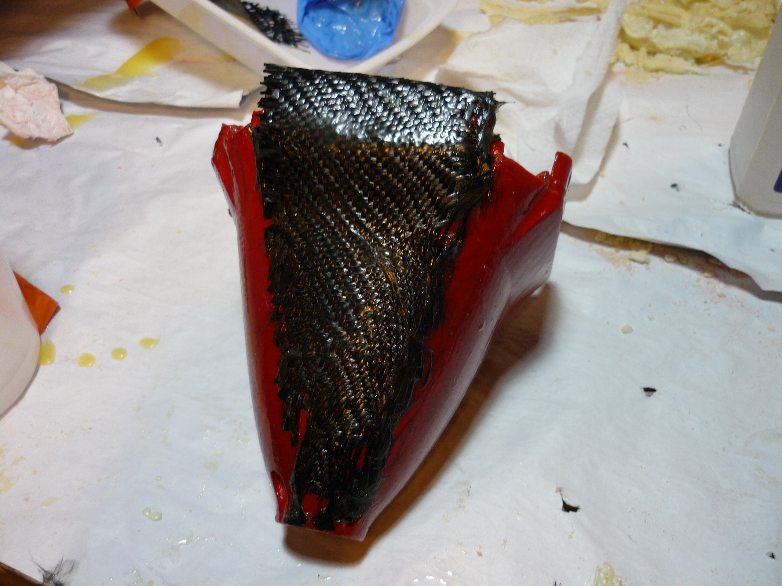
| As I had mentioned earlier, there were some fraction issues on the thruster. I had the option of cranking up the wall thickness in that area or adding an external constraint. Using an x-acto knife and some super nifty thin carbon fiber weave, I attempted to reinforce the thruster cowling. | |
 |
| I was fortunate to find scraps of thin carbon fiber cloth, remnants from an electric vehicle team. I used electrical tape to keep the weave in place and xacto-knife cut triangular shaped sections to wrap around the points of fracture on the canoe cowling. I laid the newly-epoxyed back together cowling down for a fitting | 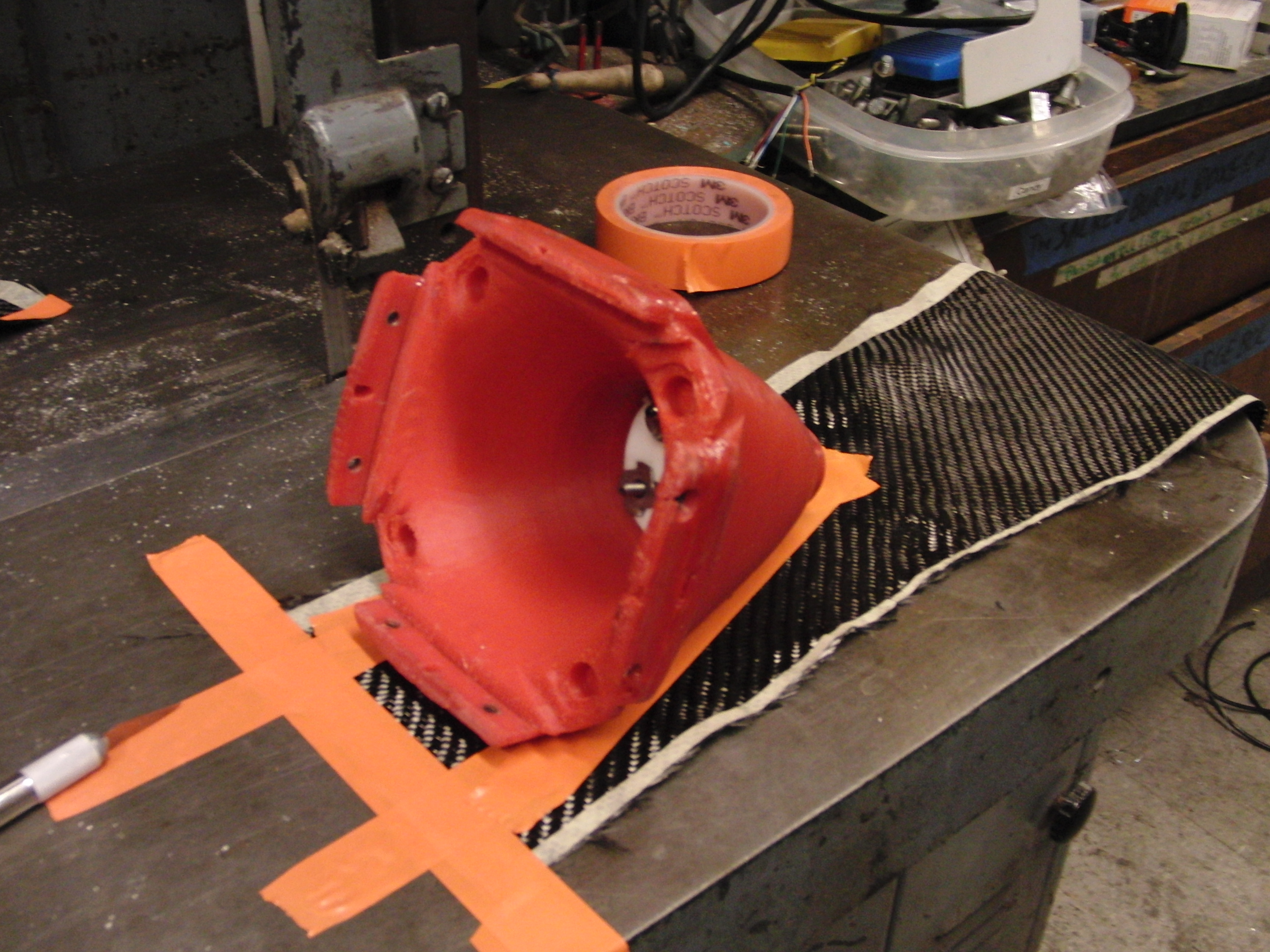 |
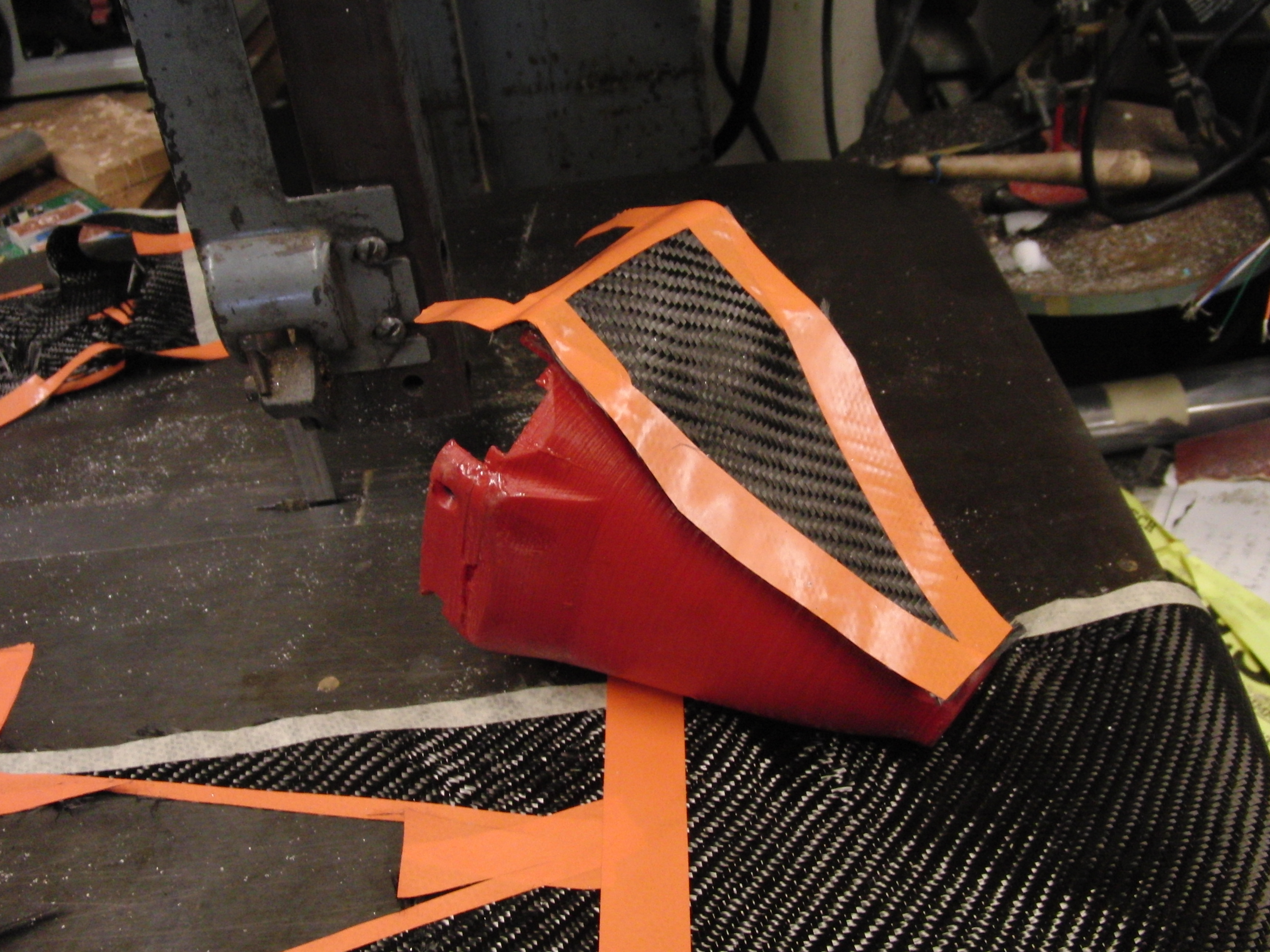 |
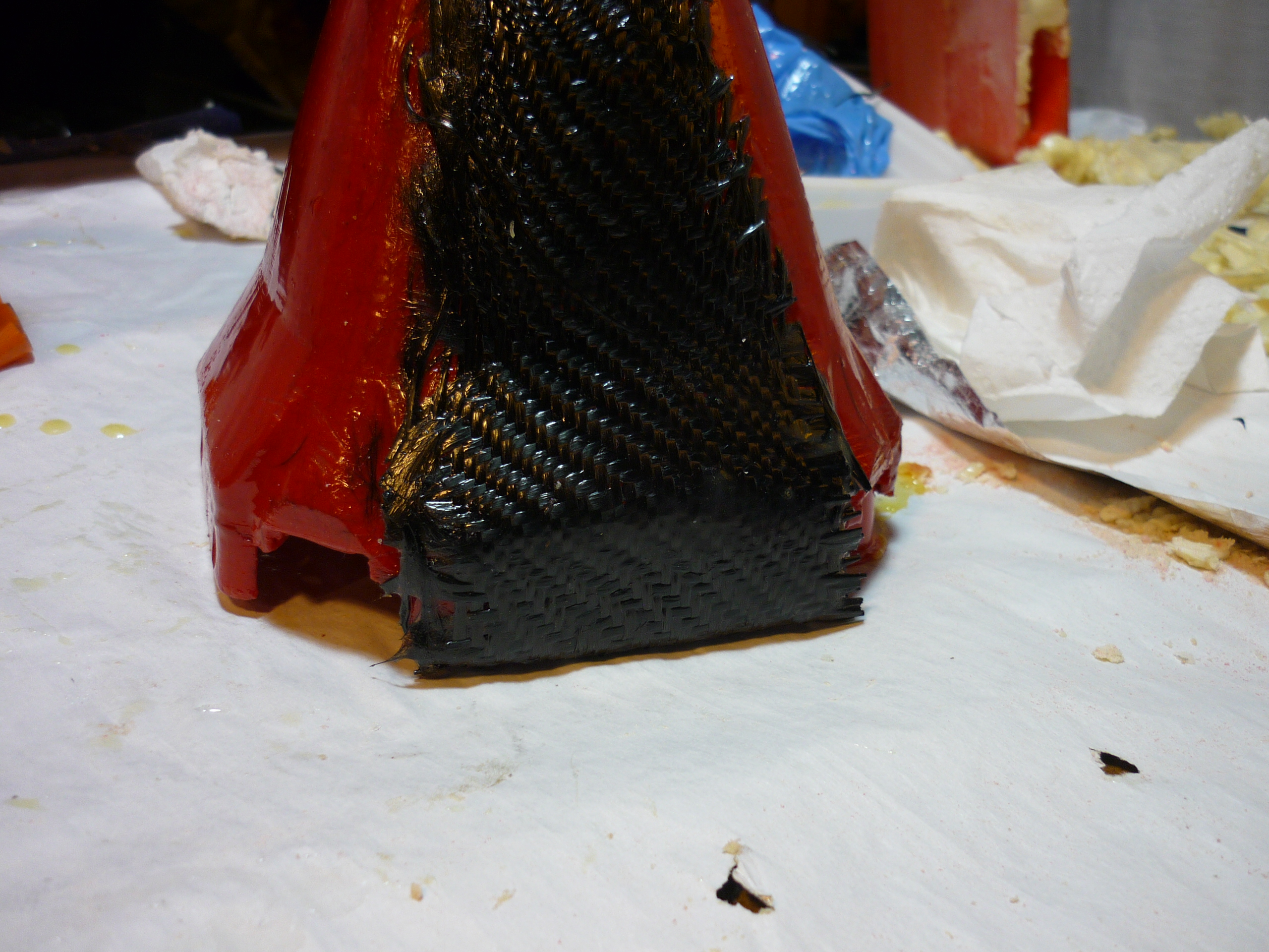
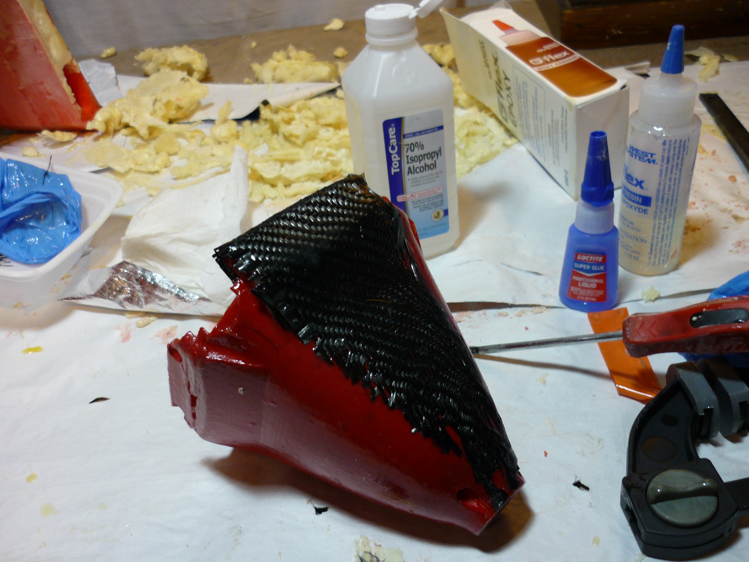
| I have never formally carbon-fibered things, I watched a friend fiber-up some hardware for the RPI Formula SAE team, but never got a chance to try it solo. As i didnt have any vacuum bag hardware at home, I started by super-gluing the back lip of the triangle to the inside of the cowling. After that dried, I mixed some GFLEX 650 two part epoxy and applied it using a latex glove. The first go came out fairly well, the edges of the fiber were a bit hard to tame. After letting it dry for a day, i hammered on it with my fist and, it left a bruise, but the cowling was fine. | 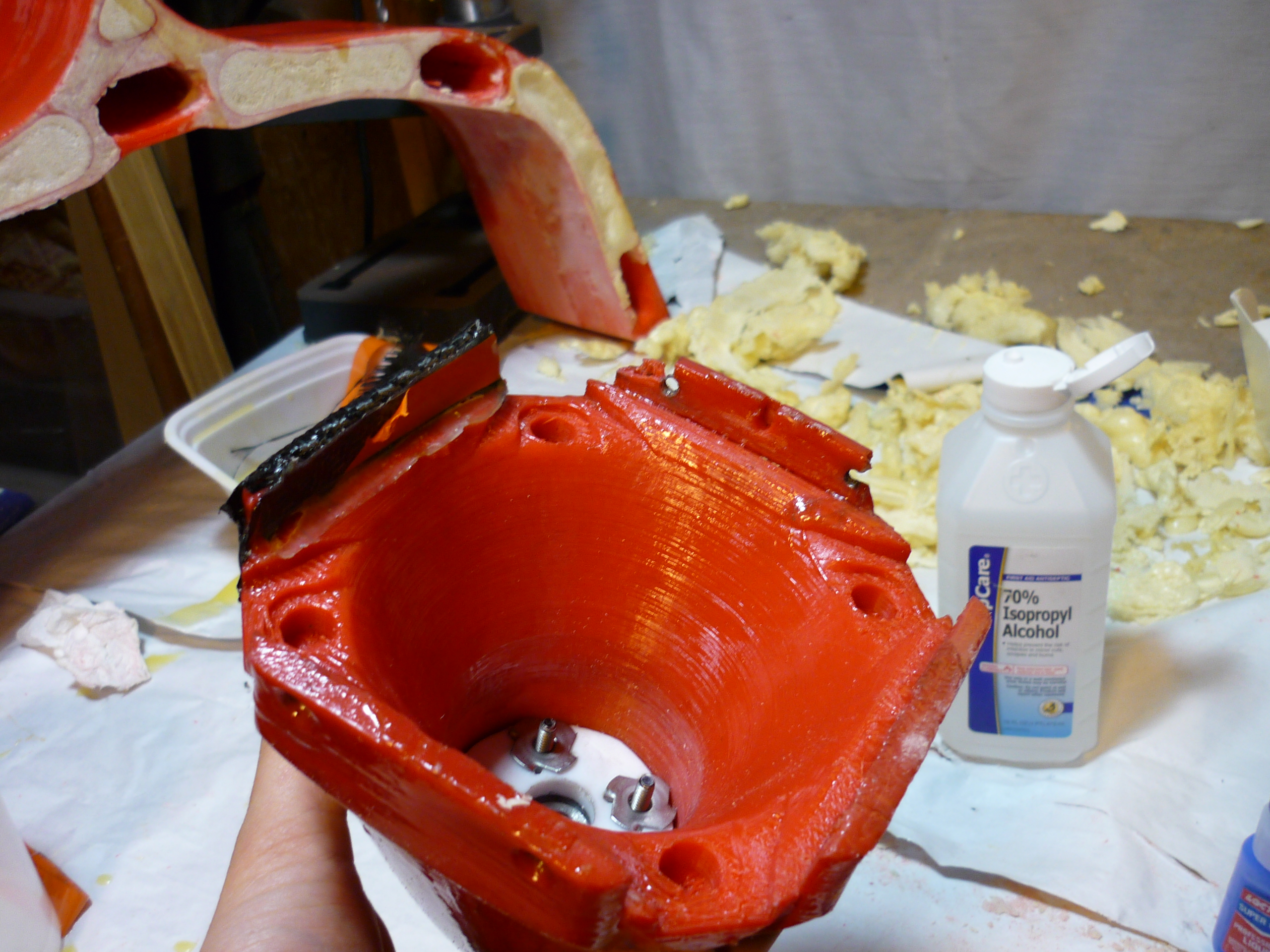 |
 |
| More
carbon fiber-ing The first test went well, I'm using this piece to test out different methods of applying the carbon fiber and reinforcing the screw-hole mount on the three remaining sides of the cowling. GFLEX is excellent at bonding to ABS, check it out. |
 |
 |
| Design Files |
| The design files are available
here: |
(There's
other photos in the photo
gallery)
Concluding
Remarks:Stand on the shoulders of comrades, its surprising how much information there is out there on submersible assemblies. Everything from propellers to cavitation CFD models are floating around in the ether of the Internet / local libraries. I learned a lot from David Gerr's propeller handbook, as well as getting feedback from peers. Comrades with experience ranging from underwater vehicles to powered kayaks chimed in with tips and tricks. In terms of future changes, using two holes for filling / emptying the casing oil would be better than one, as one would act as a vent with the other acting as the fill point. I was exciting to hear comrades ask to use the thruster for other projects, like a powered wakeboard and the like.
Details of testing the submersible thruster [Link]
If you have questions or comments, ask below or send over an email.
| Comments: |
|
HTML Comment Box
is loading comments...
|
(be
careful, im not responsible for your pricey mcmaster-carr order)
Dane.Kouttron
Rensselaer Polytechnic Institute
Electrical & Electrical Power
631.978.1650
