Dane.Kouttron
[8.5.14] Build of the Chibi-Atomic-Jeep
| What?
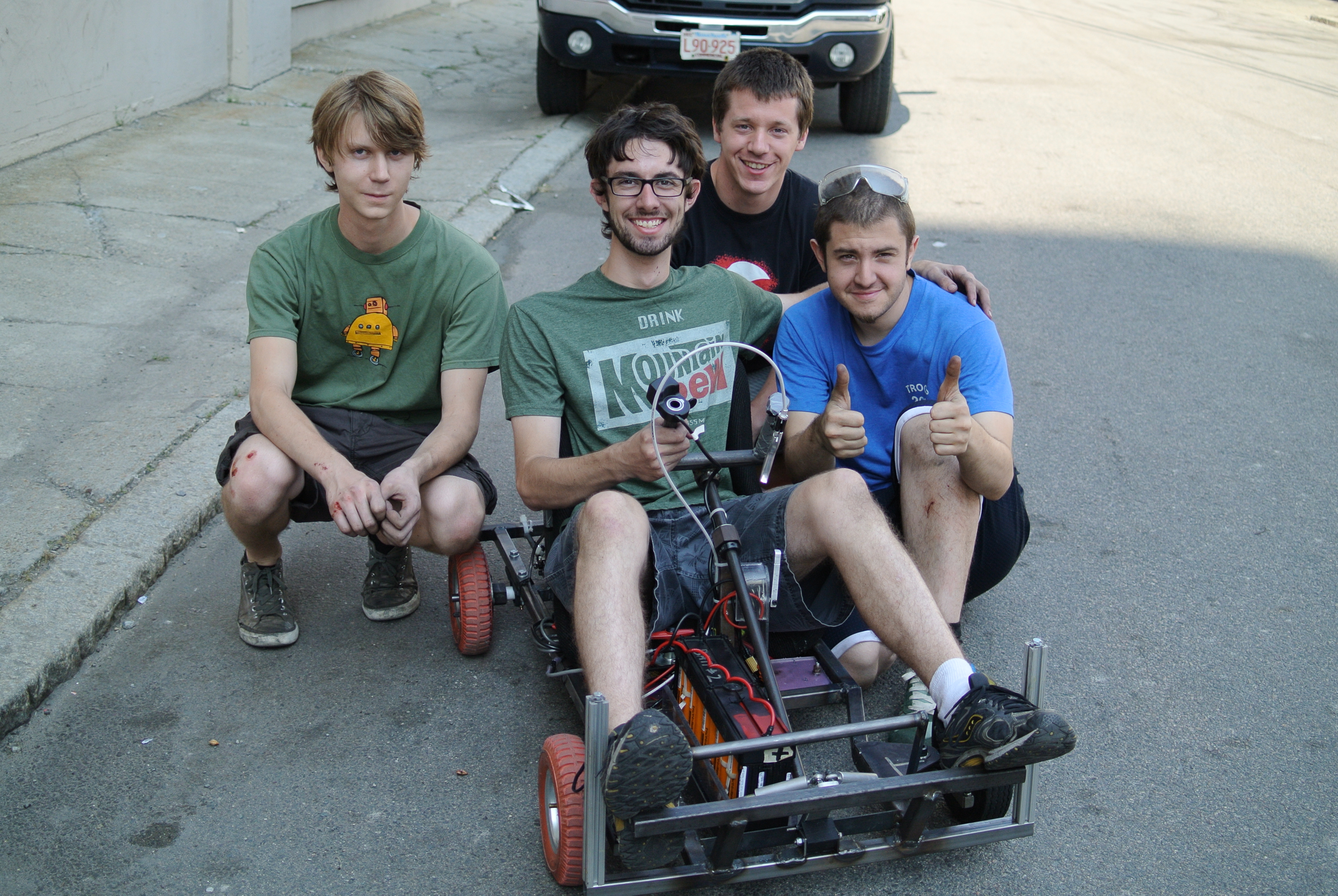
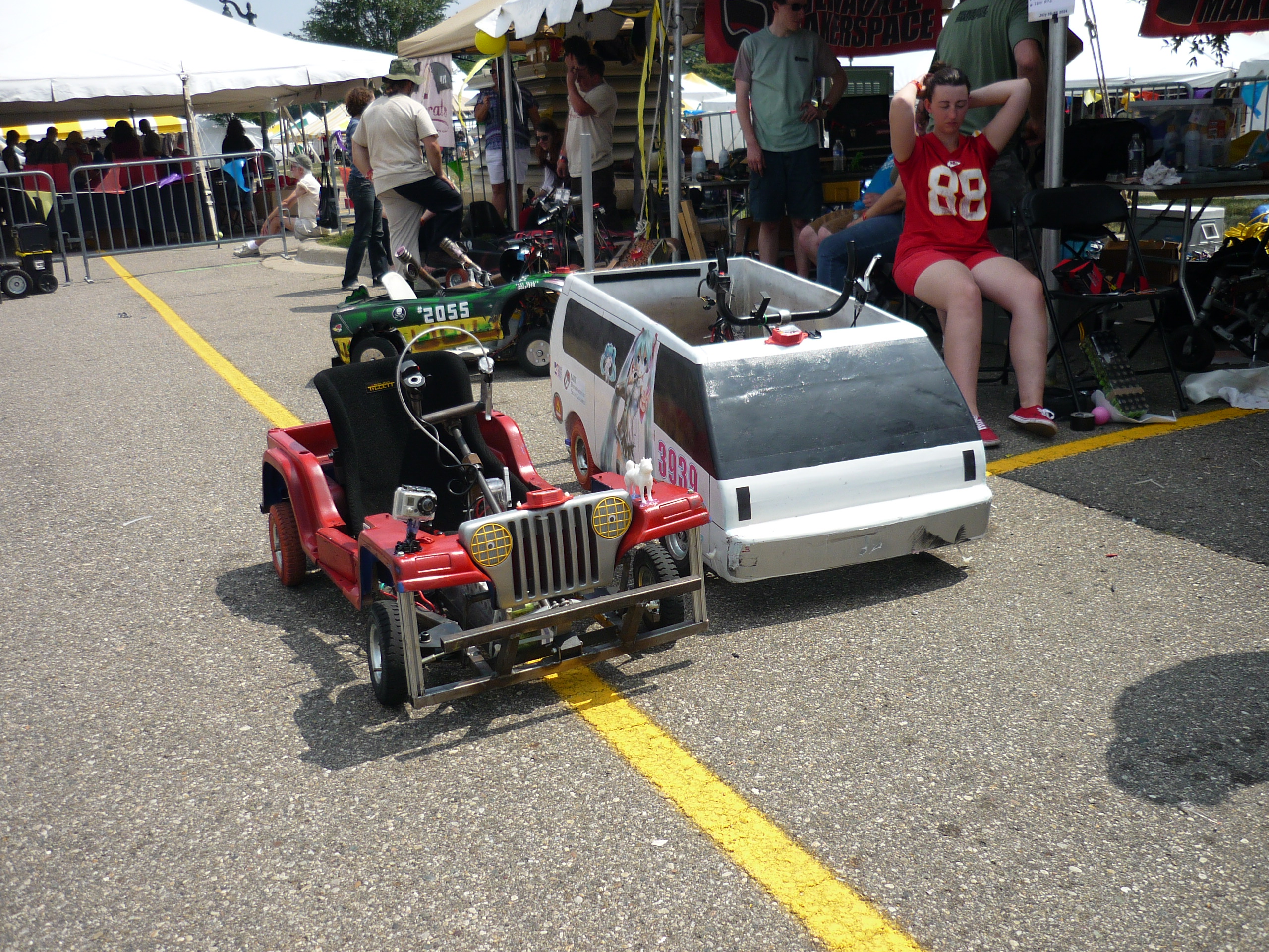
In the weeks before the Detroit Makerfaire, myself Ben, Mike, Ciaran and Rob got the chance to putz around in the just-about-complete chibi-miku-van. It was glorious. At the last moment we decided to build our own entry for the Detroit makerfaire, using whatever parts were lying around miters. What ensued was chaos driven gloriousness |
 |
 |
| What? |
Sensored Alternator |
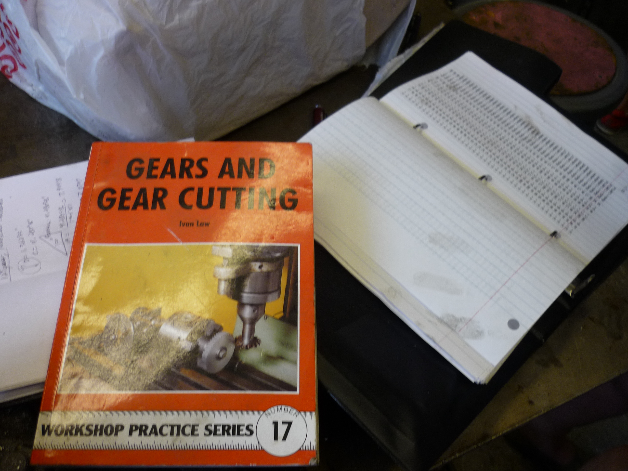
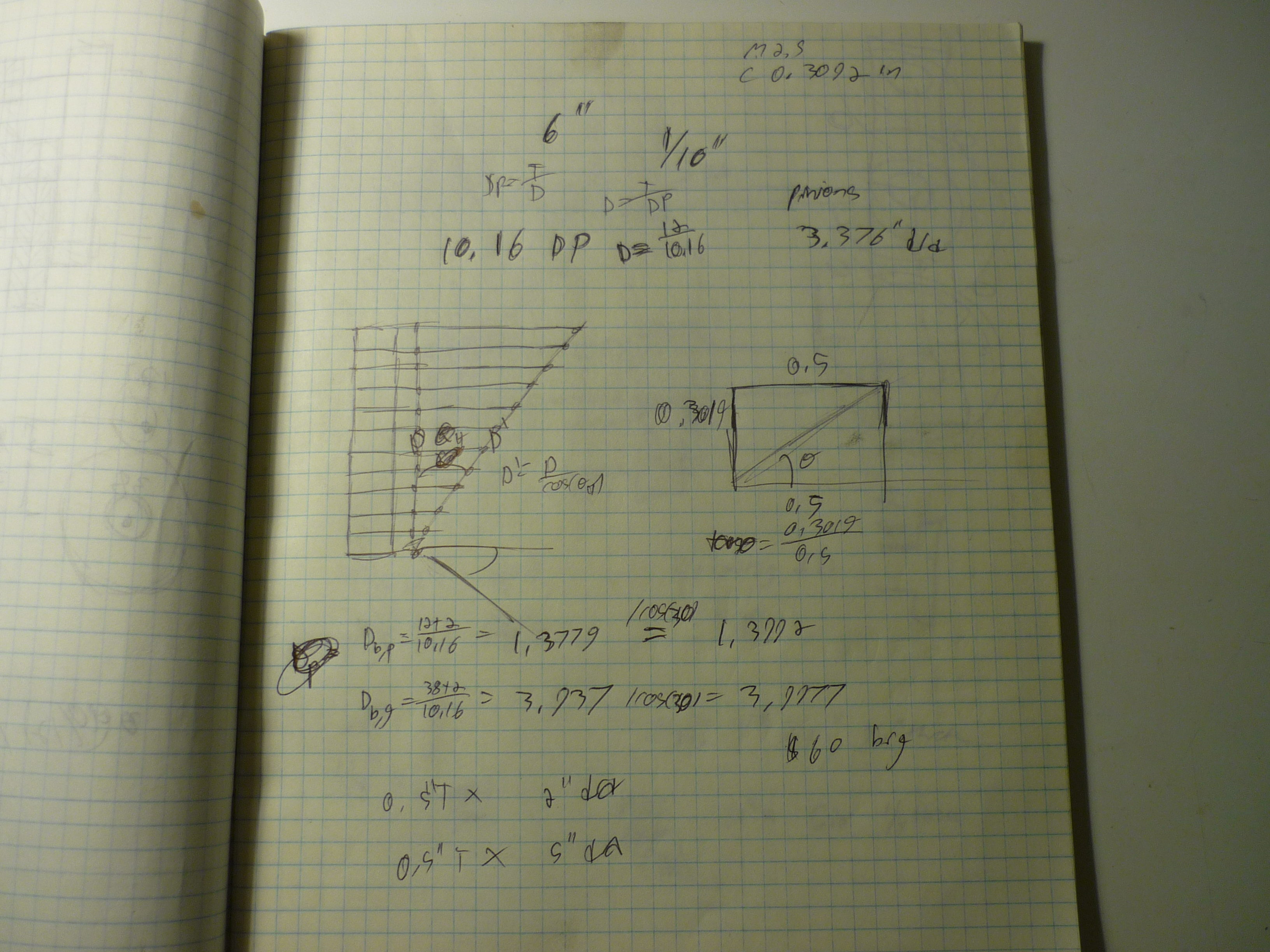
Frame and Steering | Helical Gears |
|
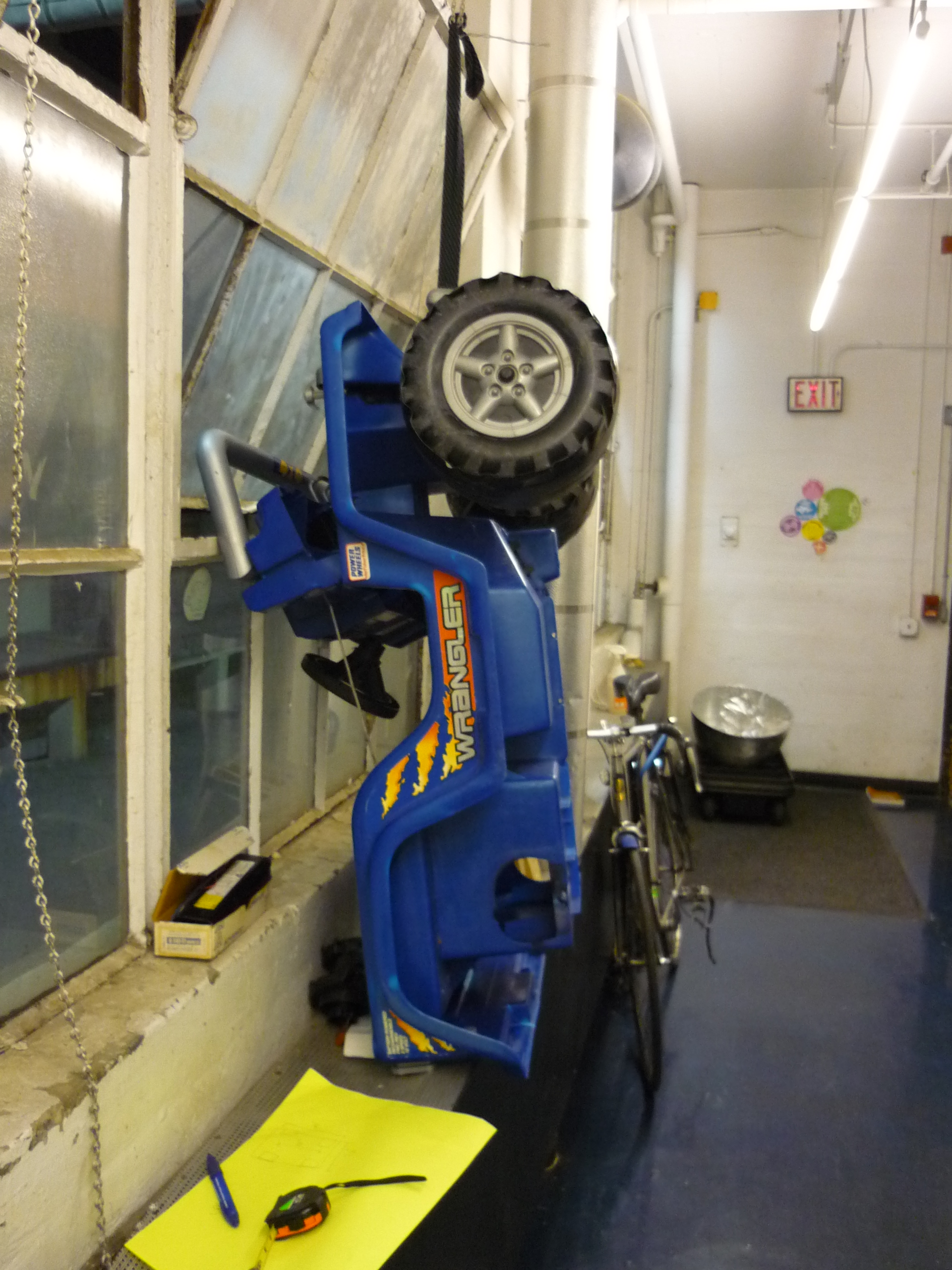
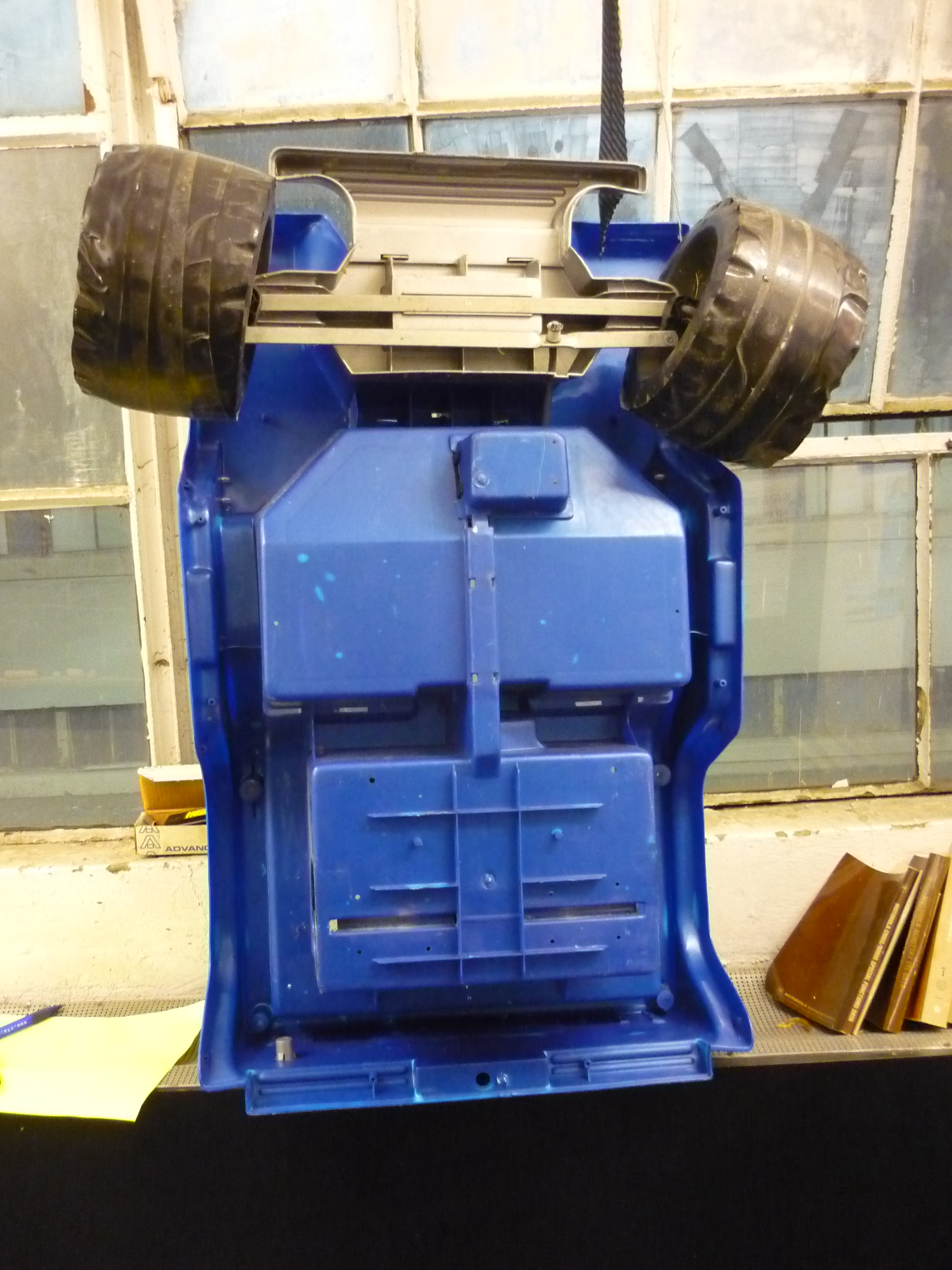
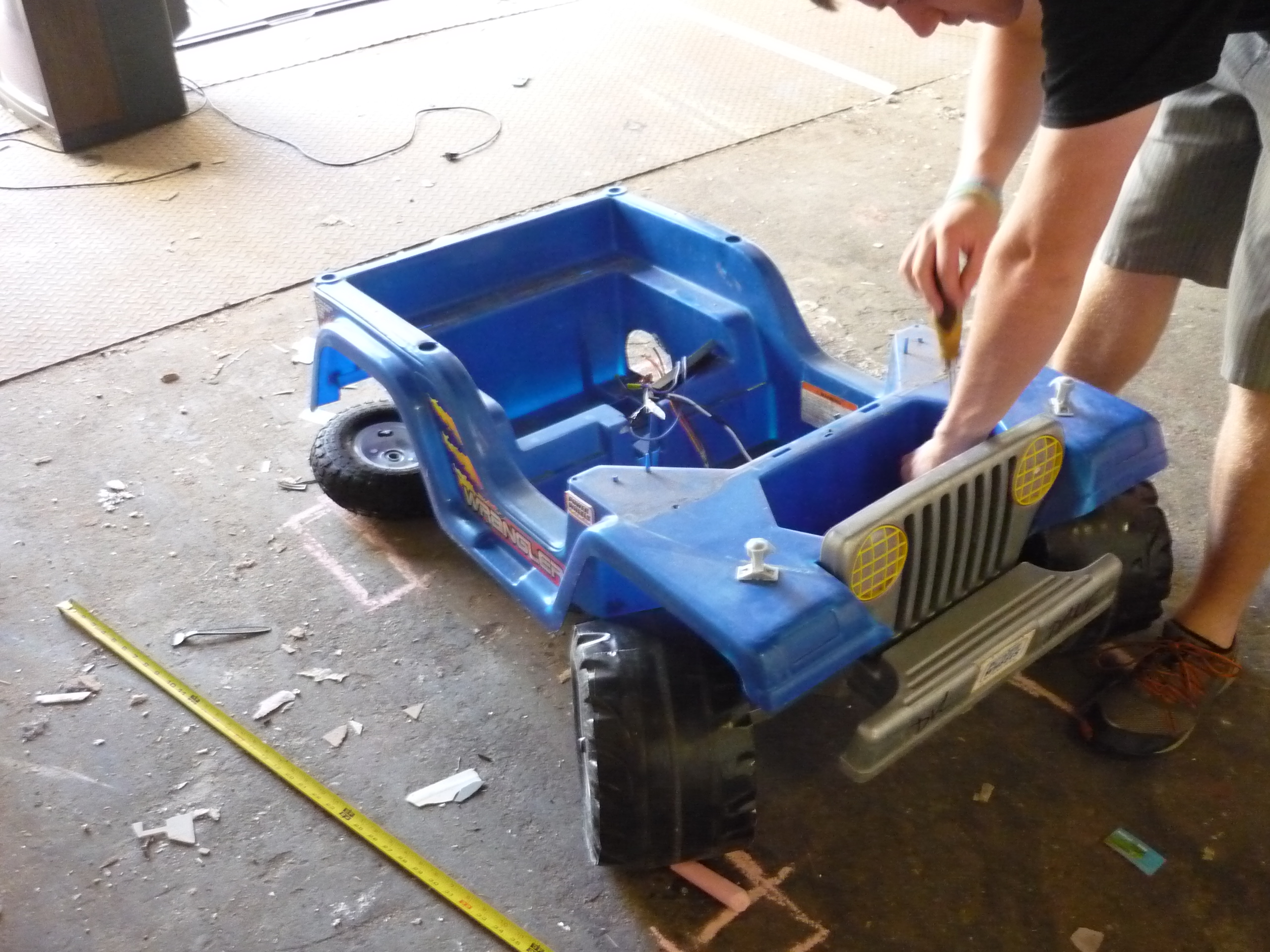
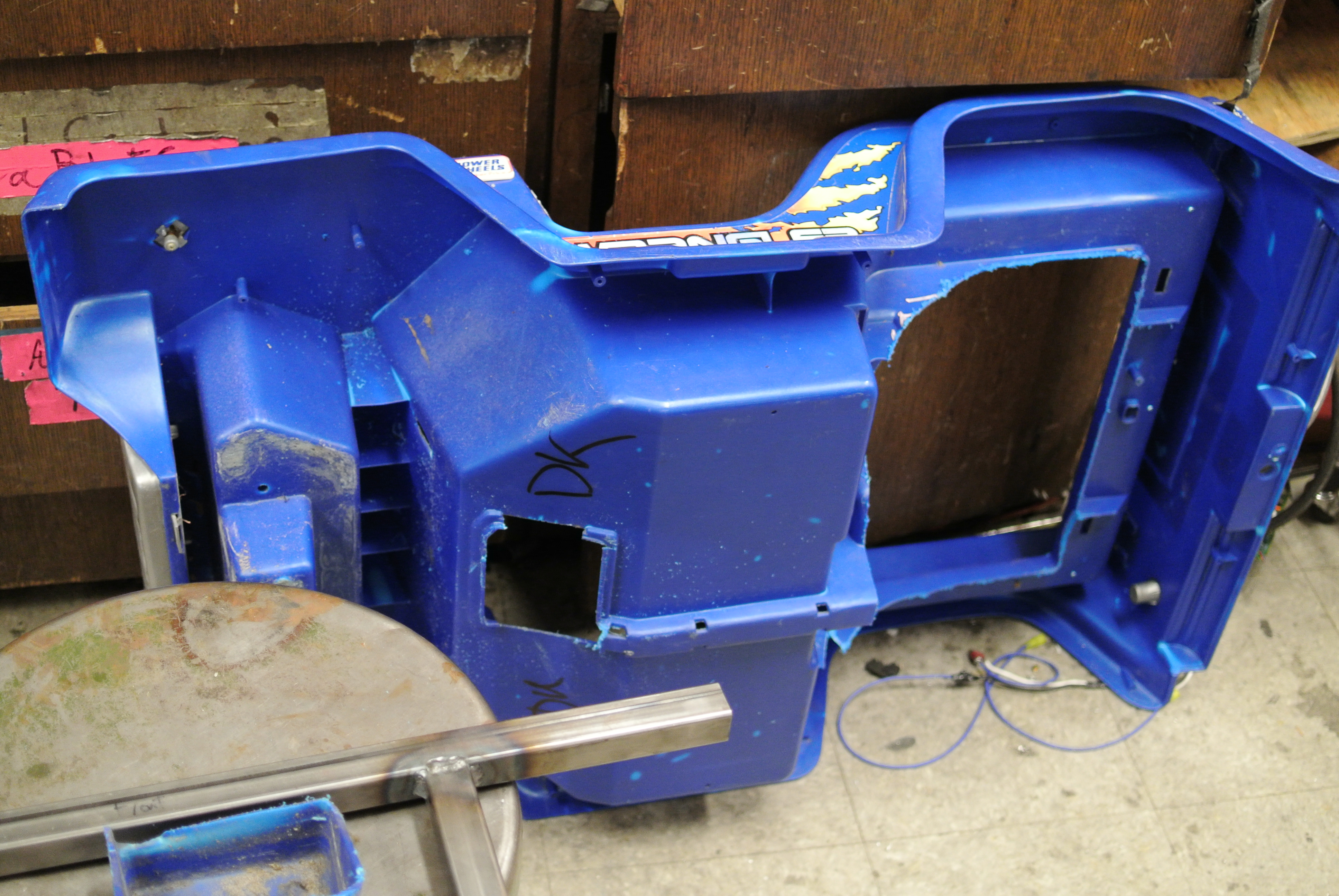
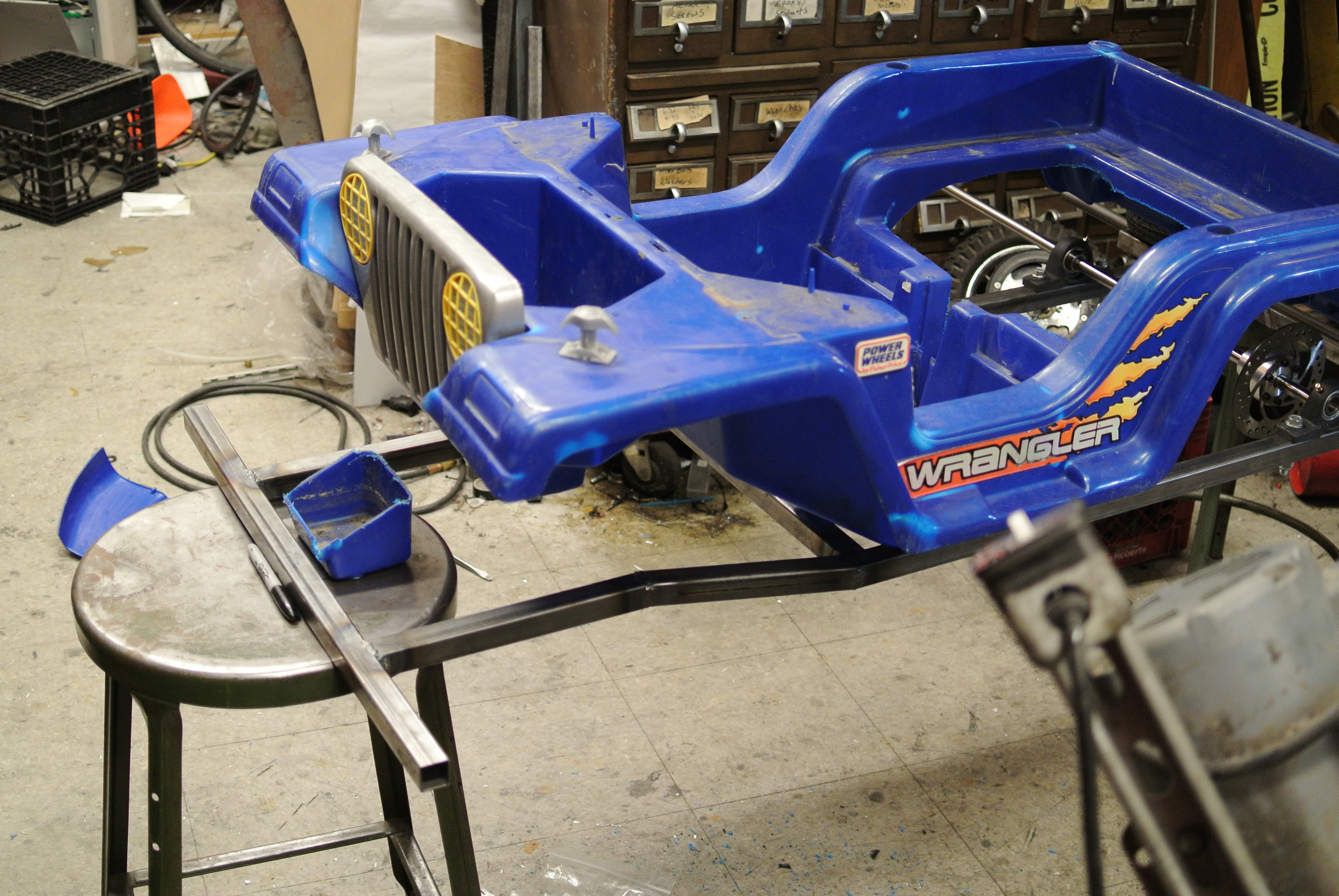
Shell |
|
Conclusion | Image Directory |
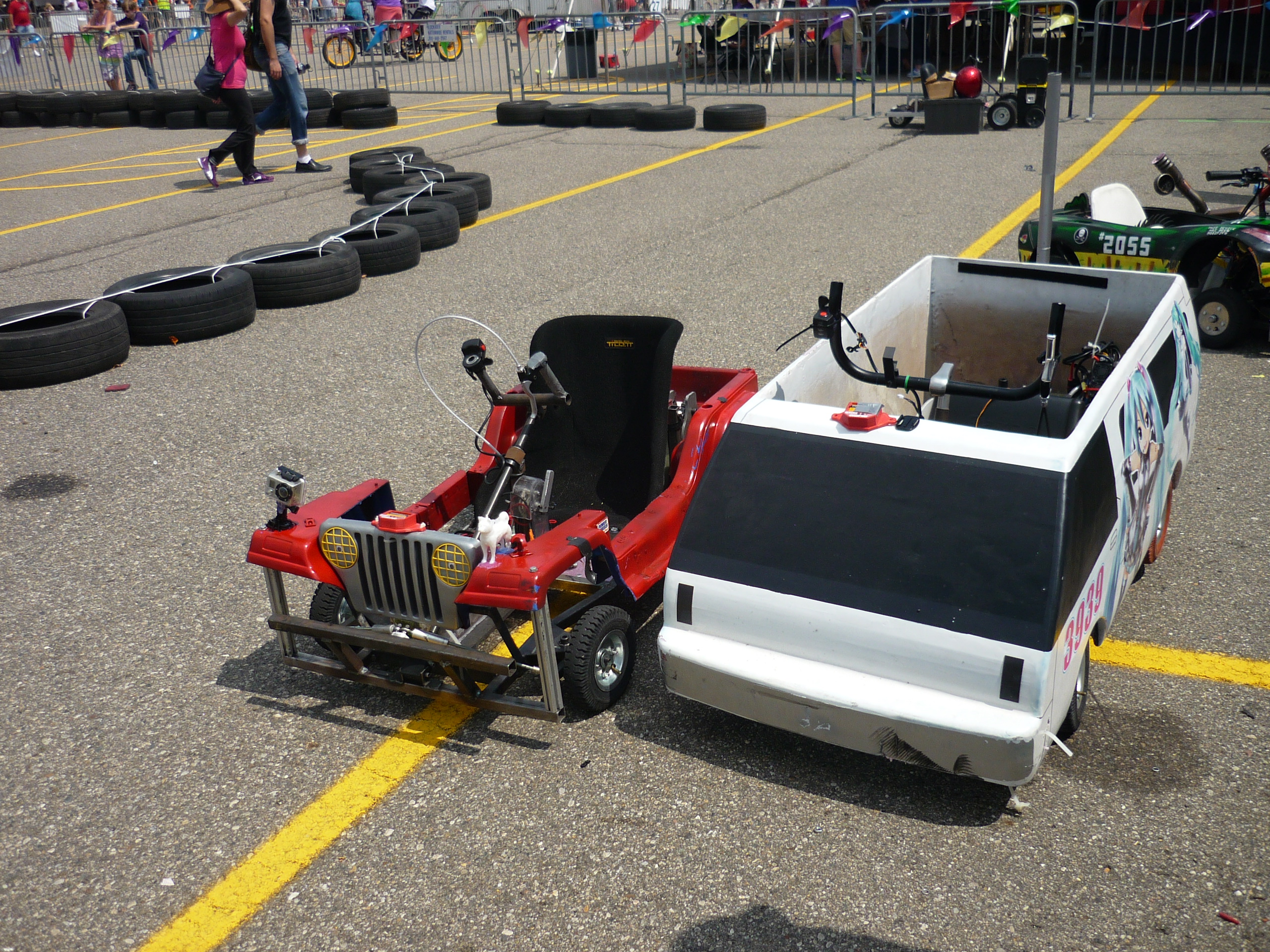
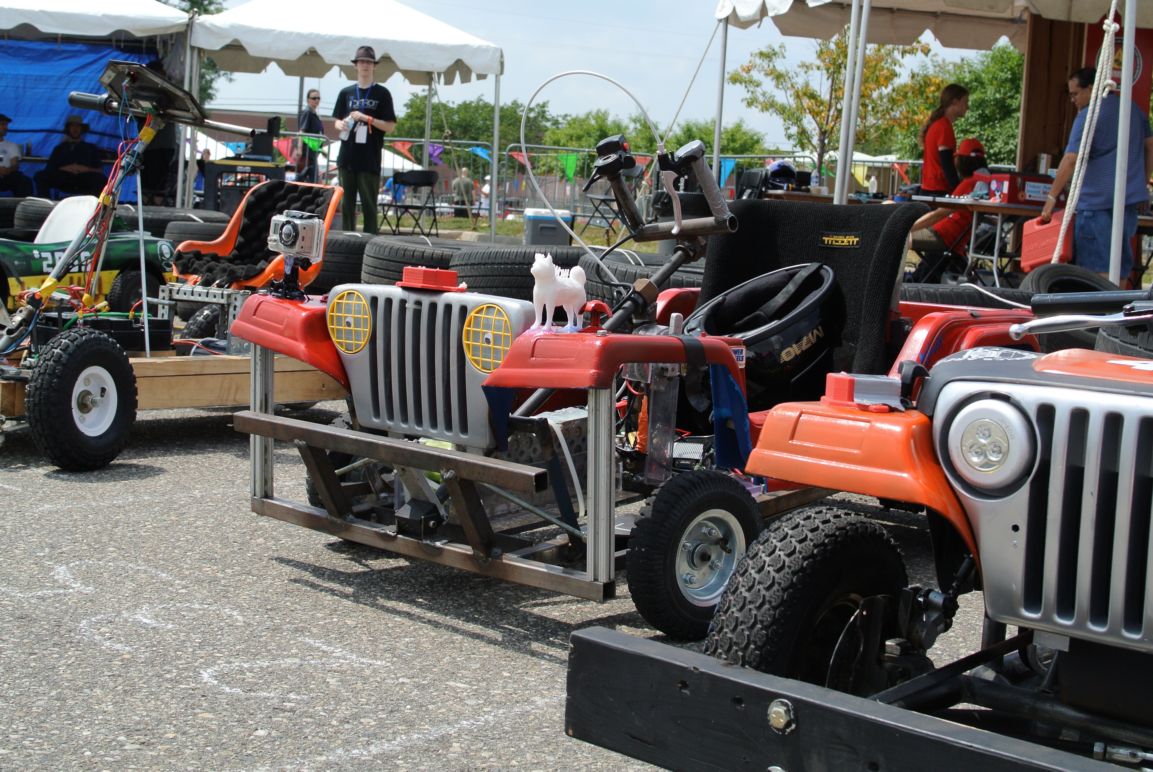
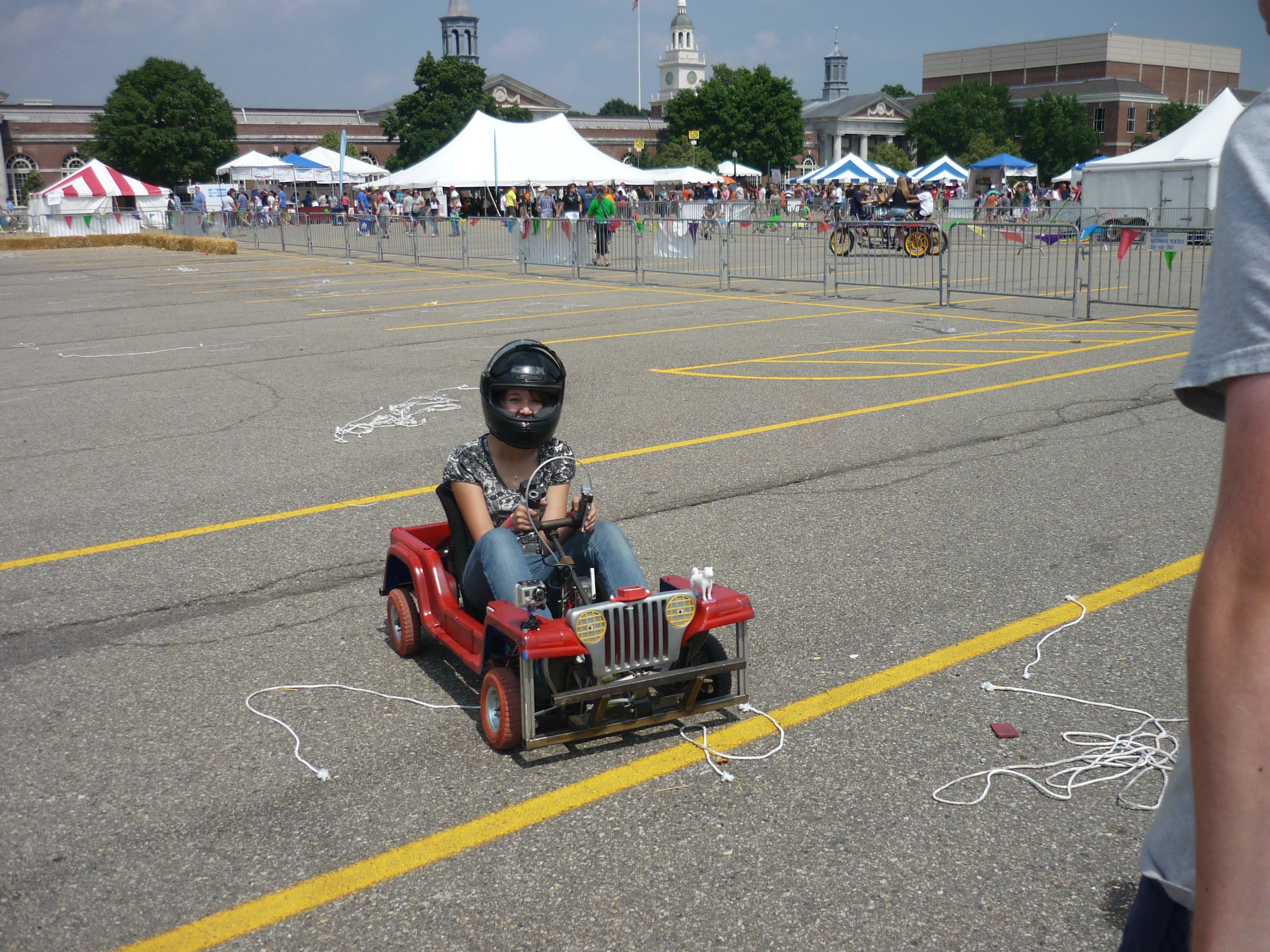
| The chibi-atomic-jeep, (red jeep-like contraption shown right) completed in less than a week and a half, raced and completed the endurance portion of the Detroit makerfaire 2014 race. We burned through NINE 8" pink harbor freight tires and TWO 10" rubber tires between the time-trials and endurance race. The cart faired surprisingly well, caused plenty of chaos on the track and was really well received. Below details the build log and competition |
| It all started with an alternator | ||
| A scrapped alternator from Charles
g's mikuvan became the center of
attention. After removing the rectification control block from the back
of the alternator, exposing the three-phase stator windings and routing
the spring-loaded brush assembly for the rotor, we were able to spool
it up from a simple sensorless motor controller. Ben
K donated a very nice, sensored, current controlled kelly
controller to the build, so the next move was to push for adding a
hardware position sensor to the alternator. |
 |
 |
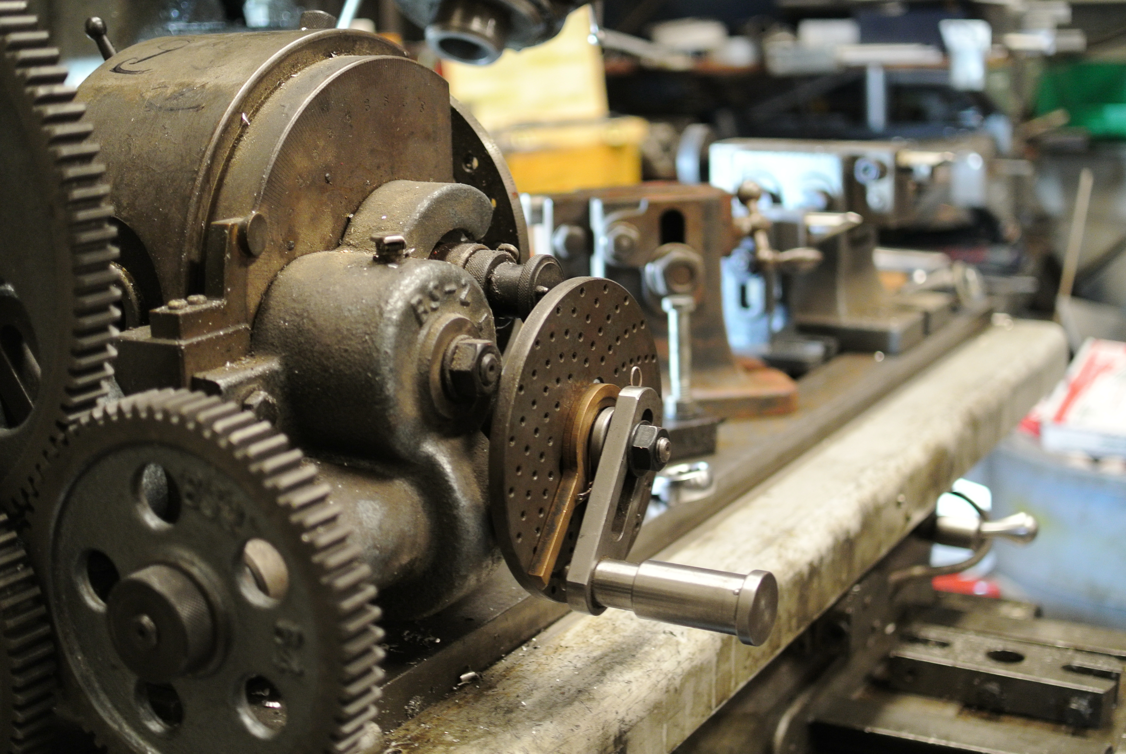
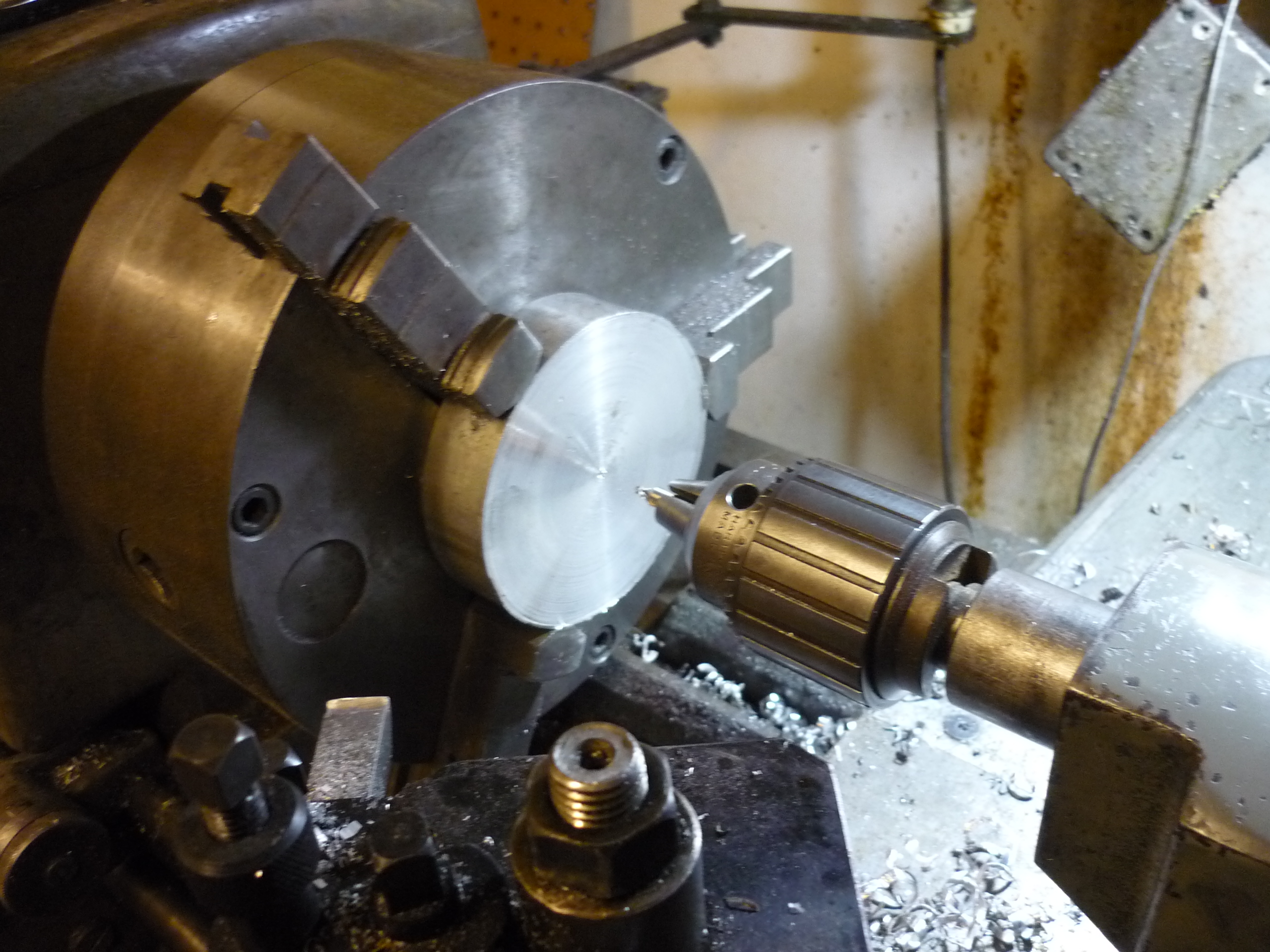
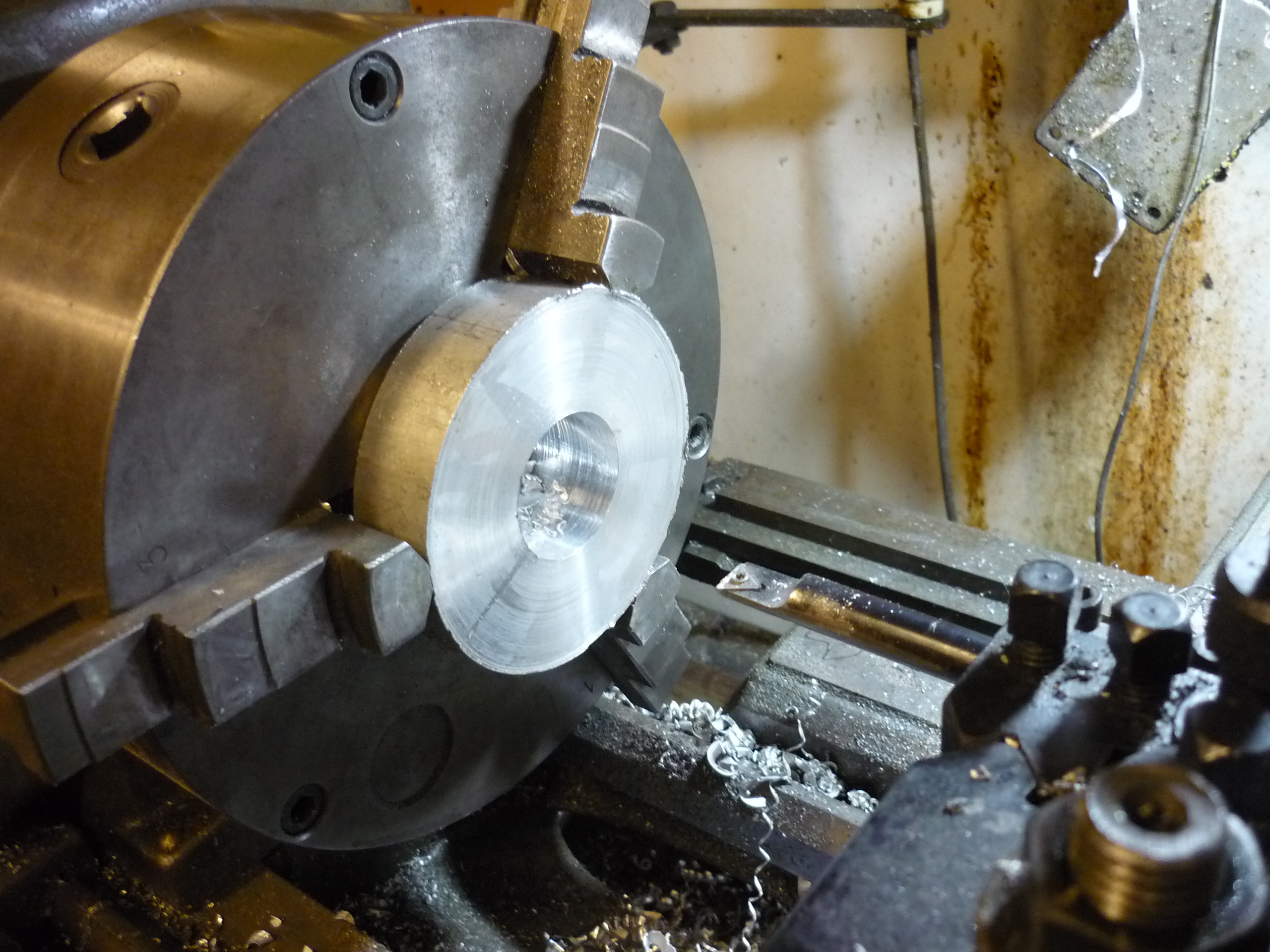
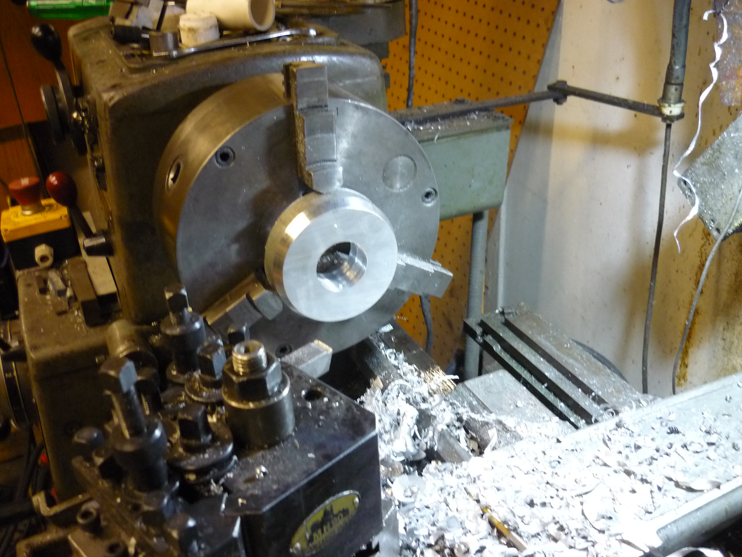
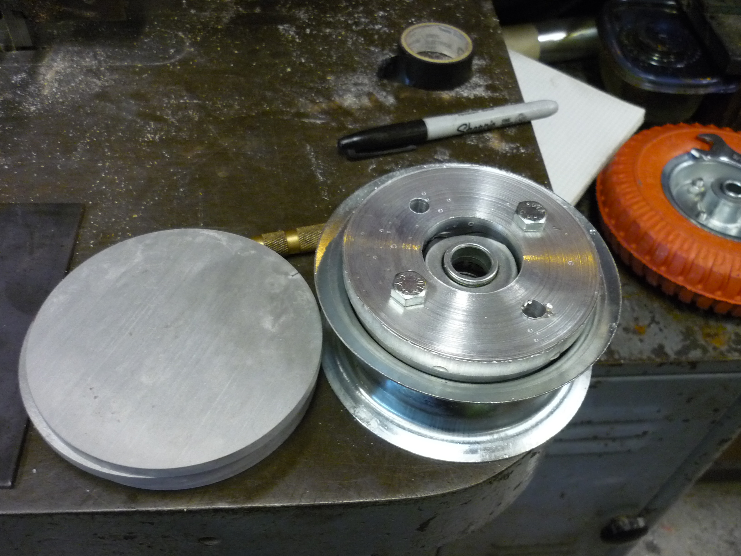
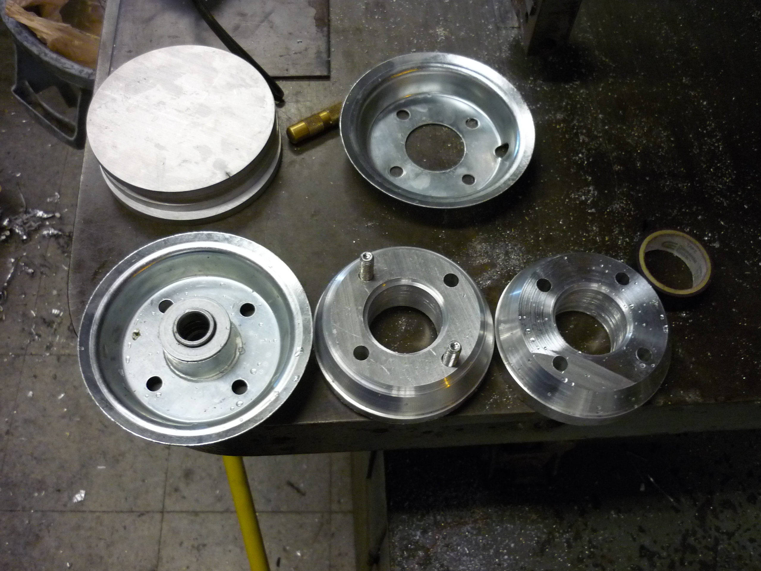
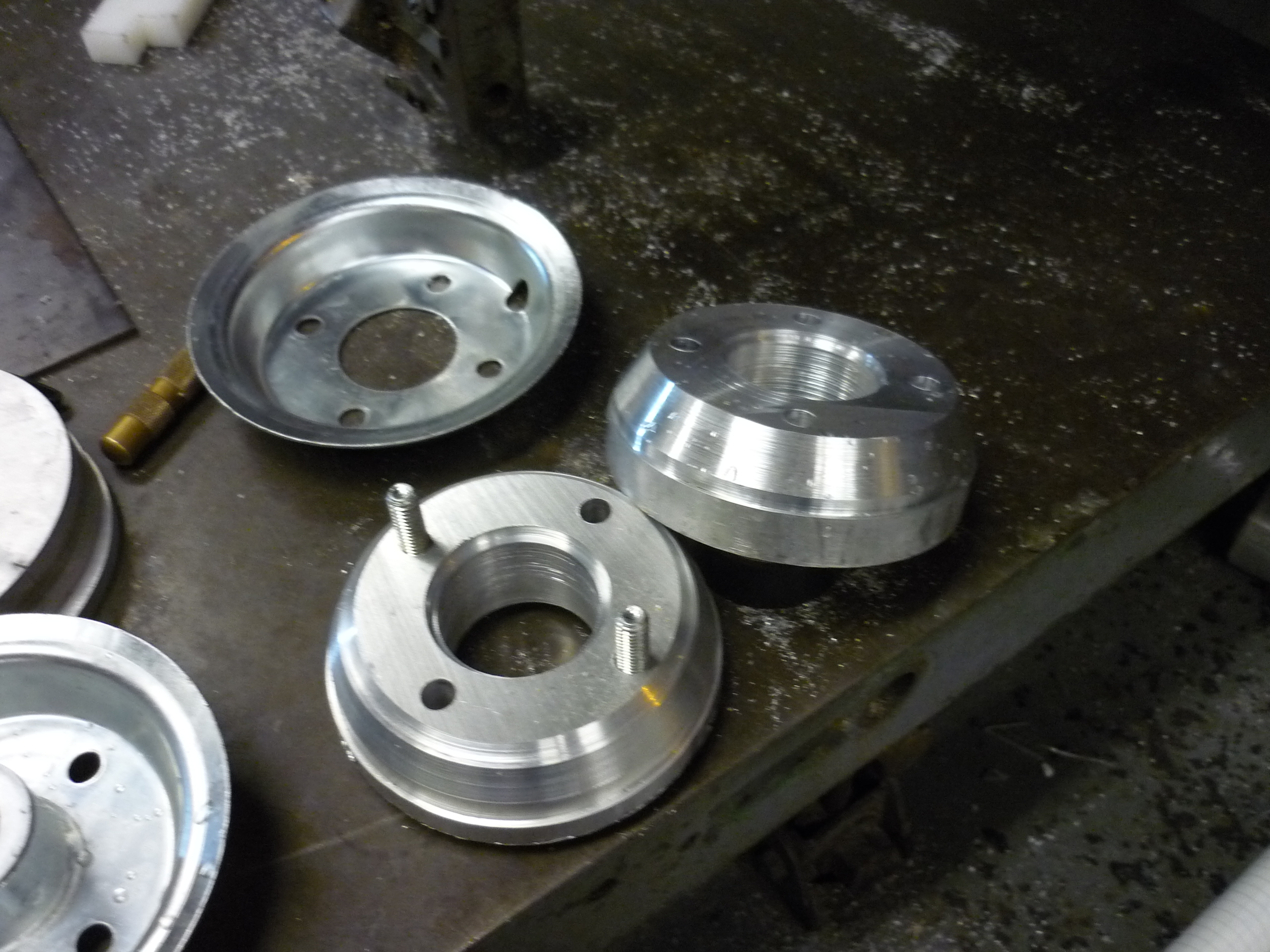
| Given that the alternator only has an output on the pulley side, and that there is only a relatively short, stumpy drive, there is little room for a sensor mount. A hole on the opposing side was bored out, leaving the casing lip in place so the alternator bearing would remain in place. This is where the awesome happened. Did you know a cd rom drive has a 12 pole motor (and an associated 12 pole magnetic rotor housing? Ben magically did. after gluing down three hall-effect sensors and designing a really fancy support jig (including flexures) the sensored alternator was born. | 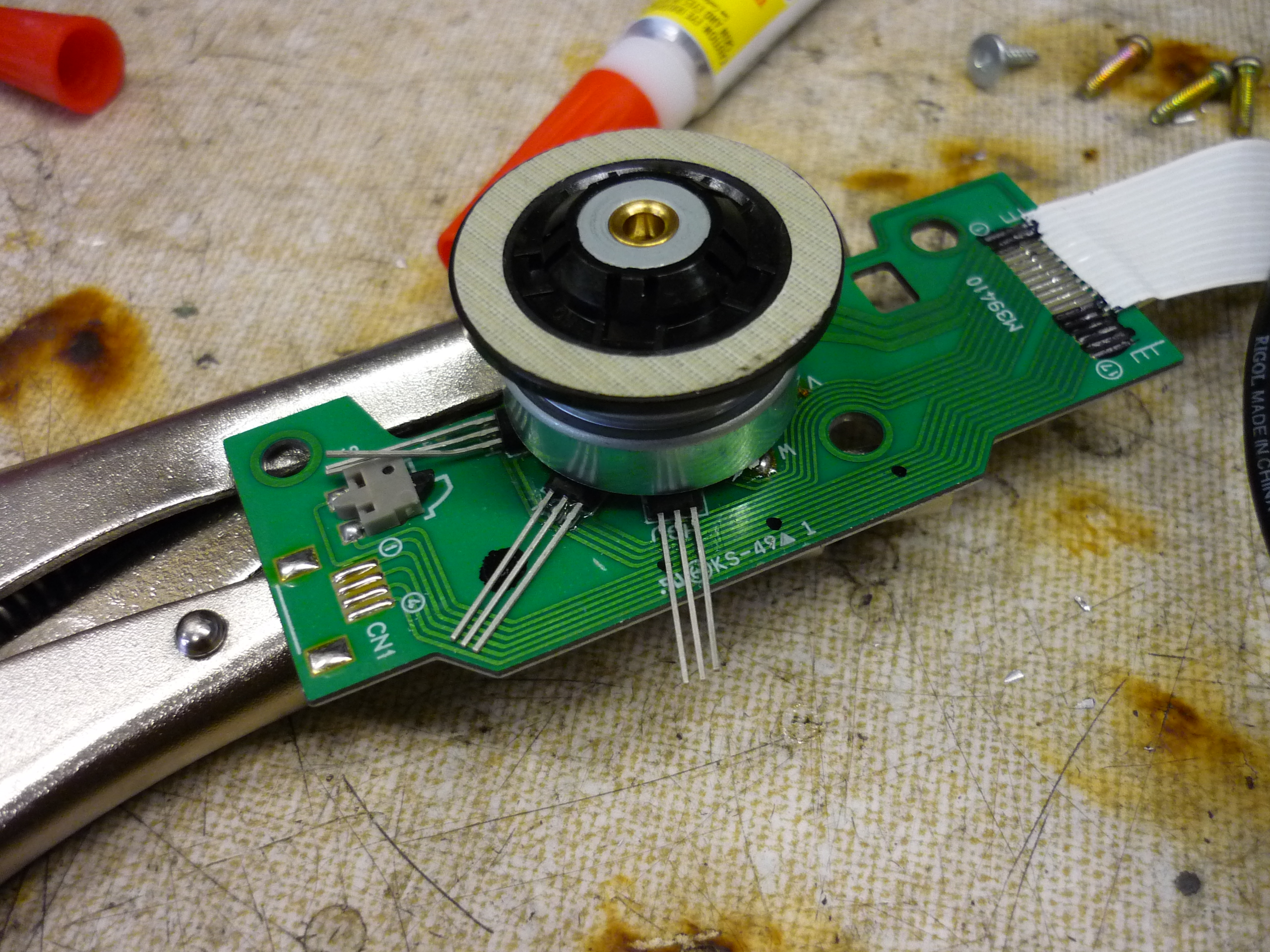 |
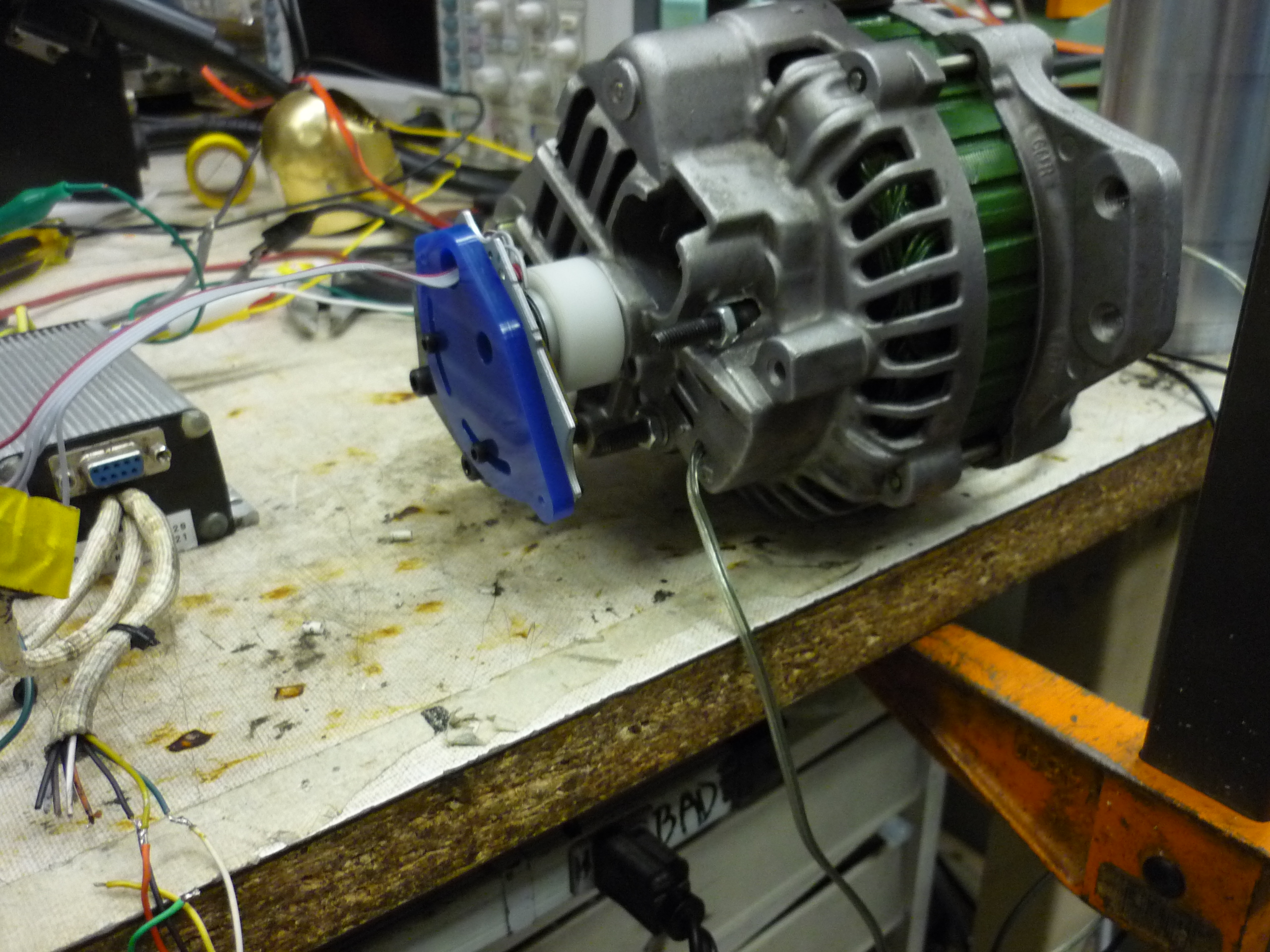 |
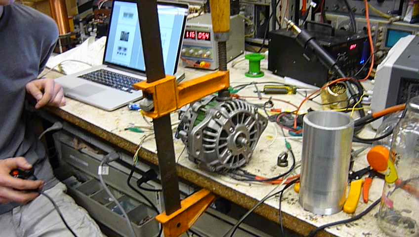
| Look
at this beast. Ben's design featured a movable sensor mount, to compensate for starting rotor position. Shown (right) is the sensored alternator clamped to the labbench. |
|
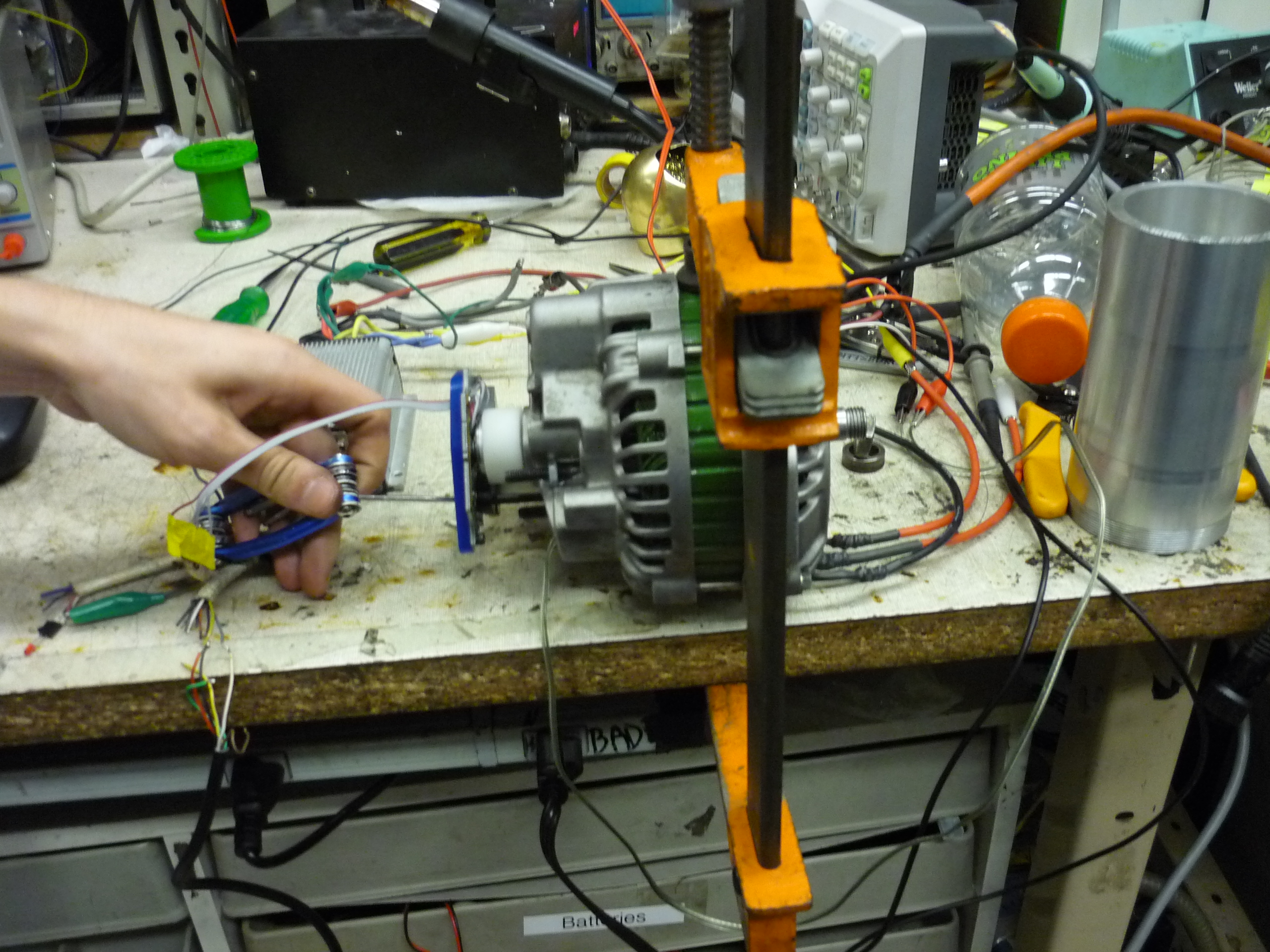 |
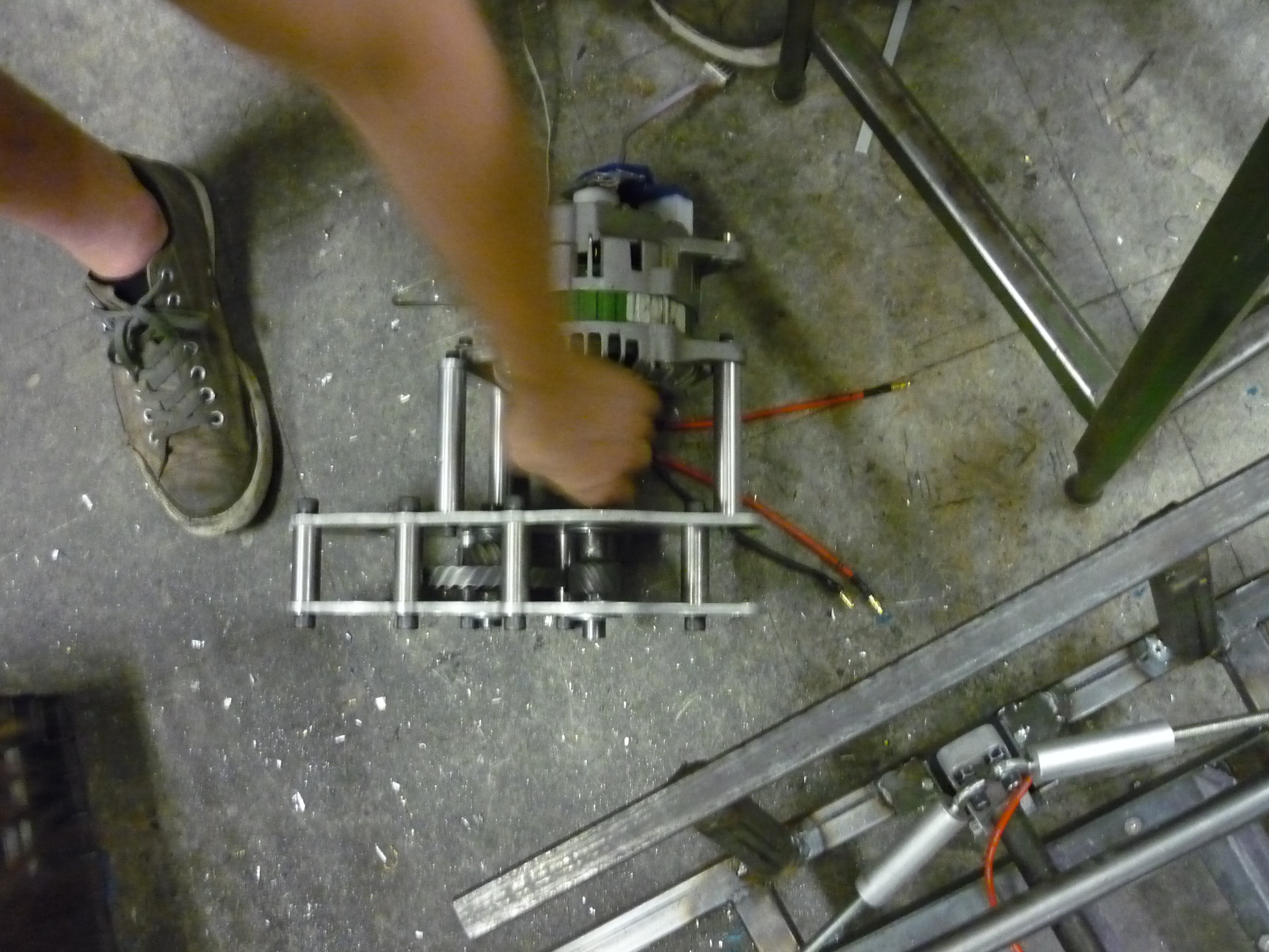
| The three short feeds were tied to the three phase stator, the speaker-wire 2 conductor cable was tied to the rotor field and the kelly controller was tied directly to the sensor board for the first flight of the sensored alternator | 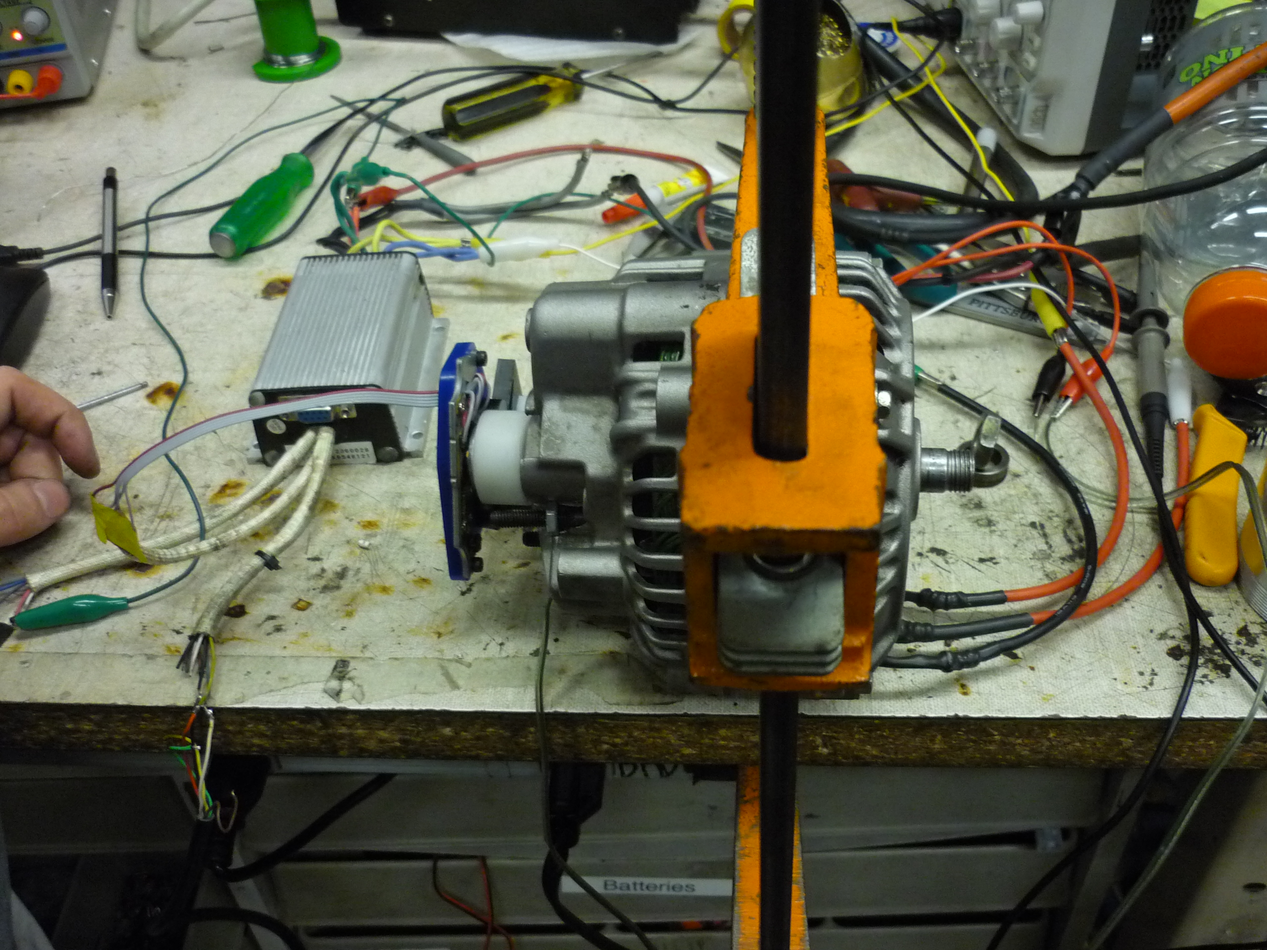 |
 |
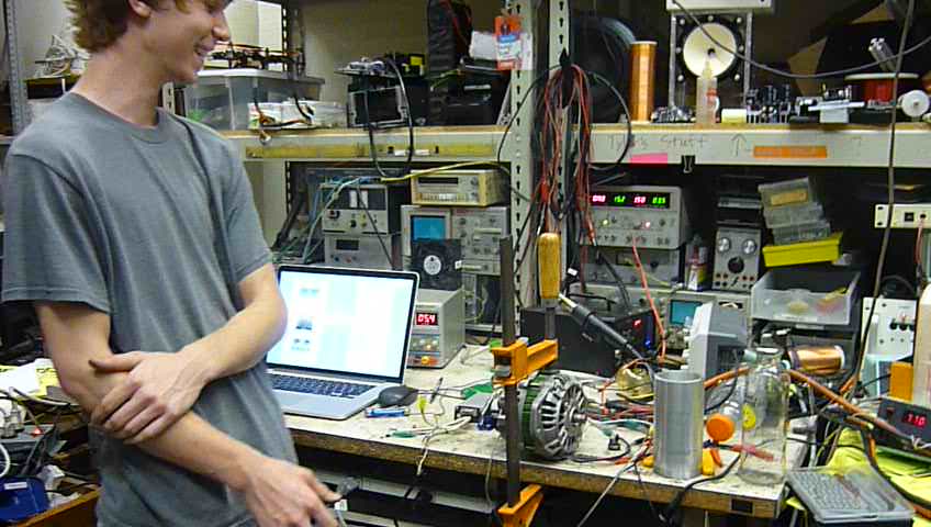
| Sensored
Alternator Spoolup |
|
| Thats
quite a bit of KV / RPM. While we didnt get a chance to measure the kv/rpm at different field control currents, it varied substantially. For a field current we used everything from 5A (saturated) to 0A (induction drive). What would have been interesting is plotting a 3d torque vs rpm vs field current curve, unfortunately that heavily requires a dyno. |
| Frame & Steering | ||
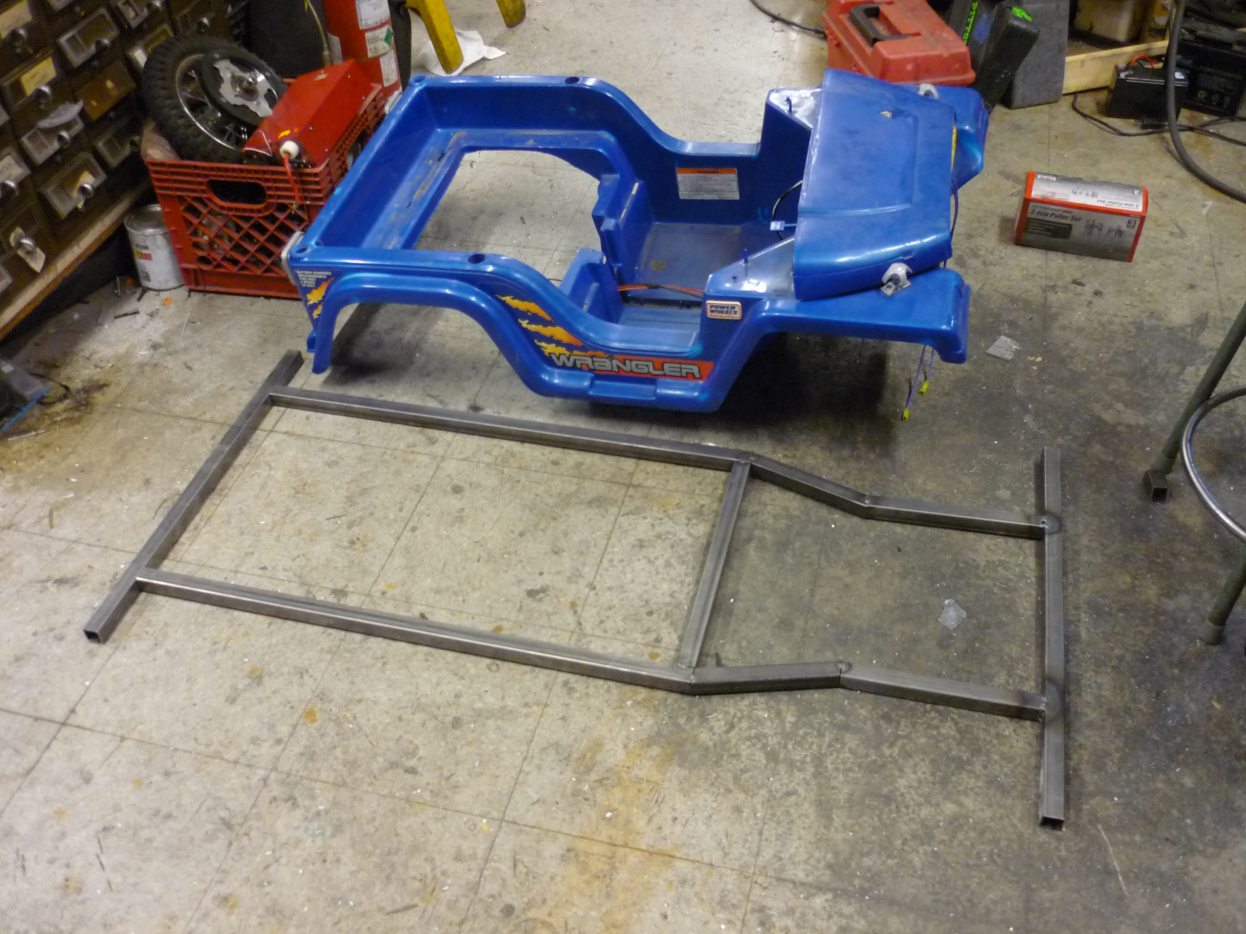
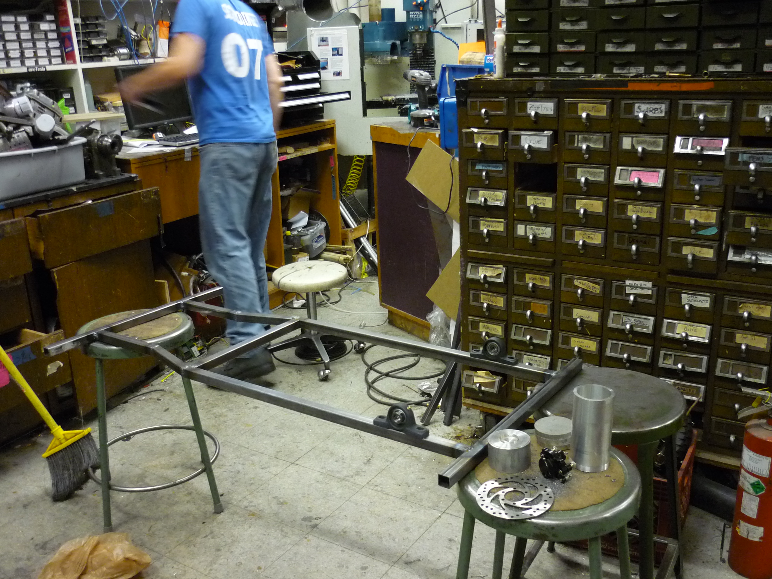
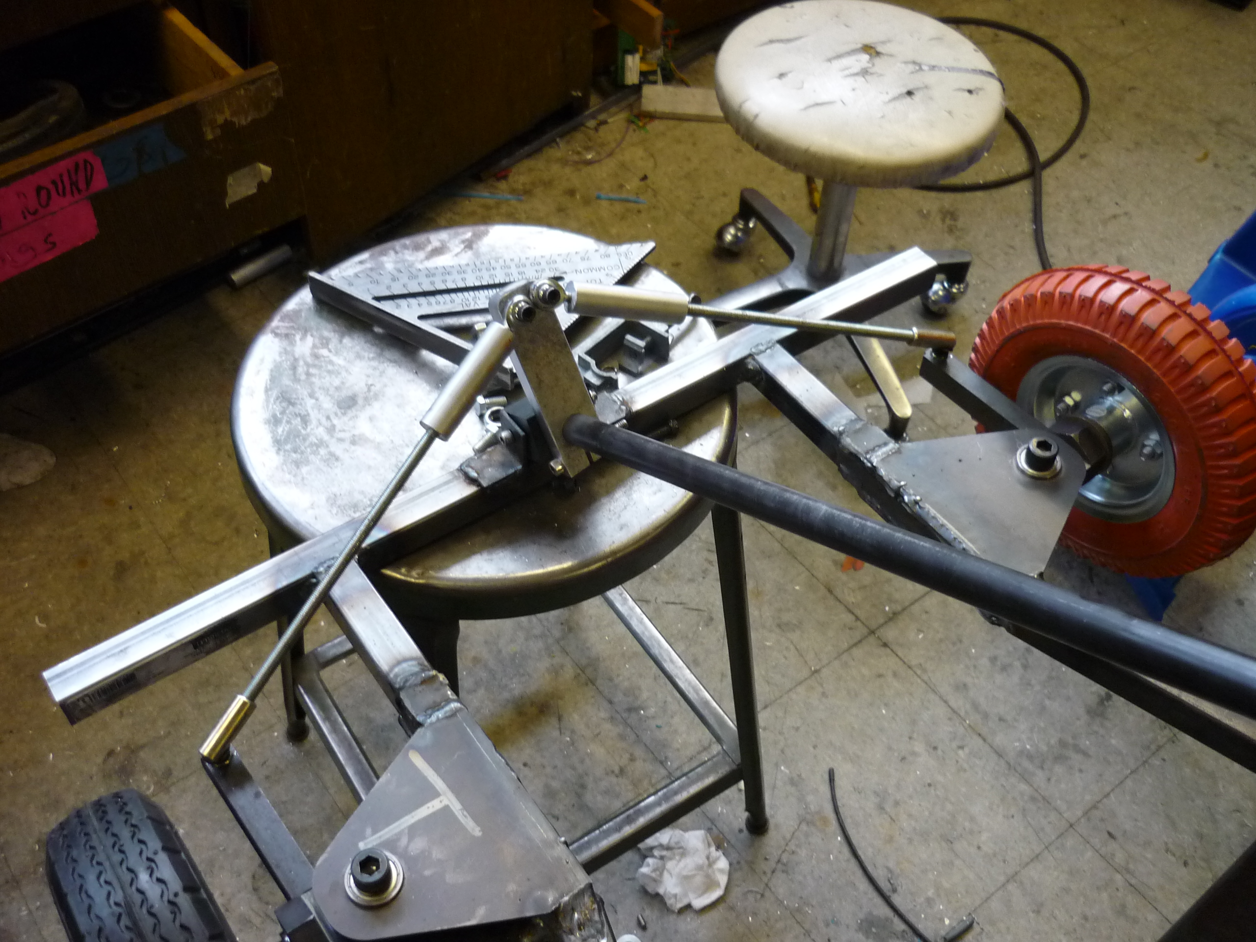
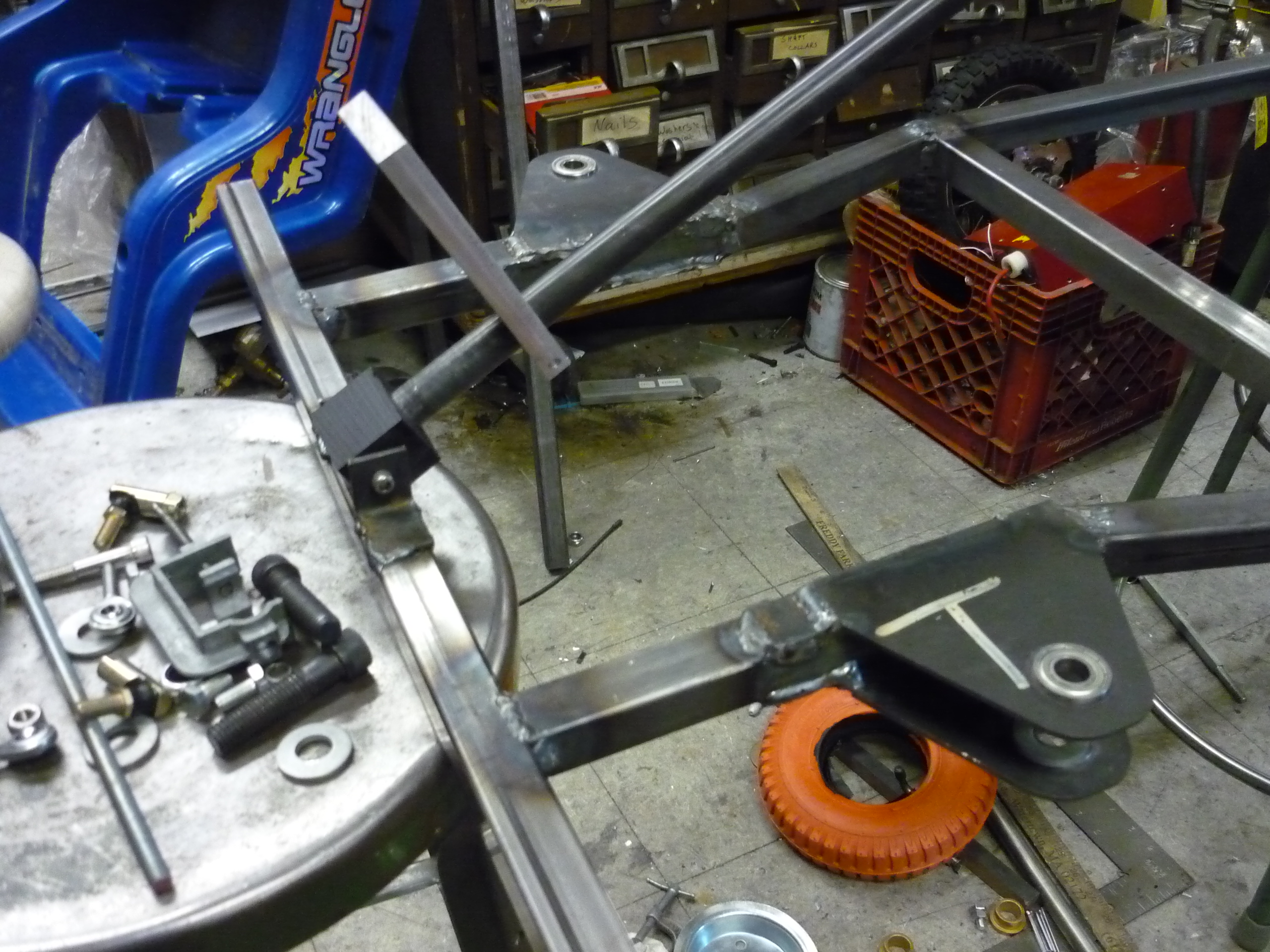
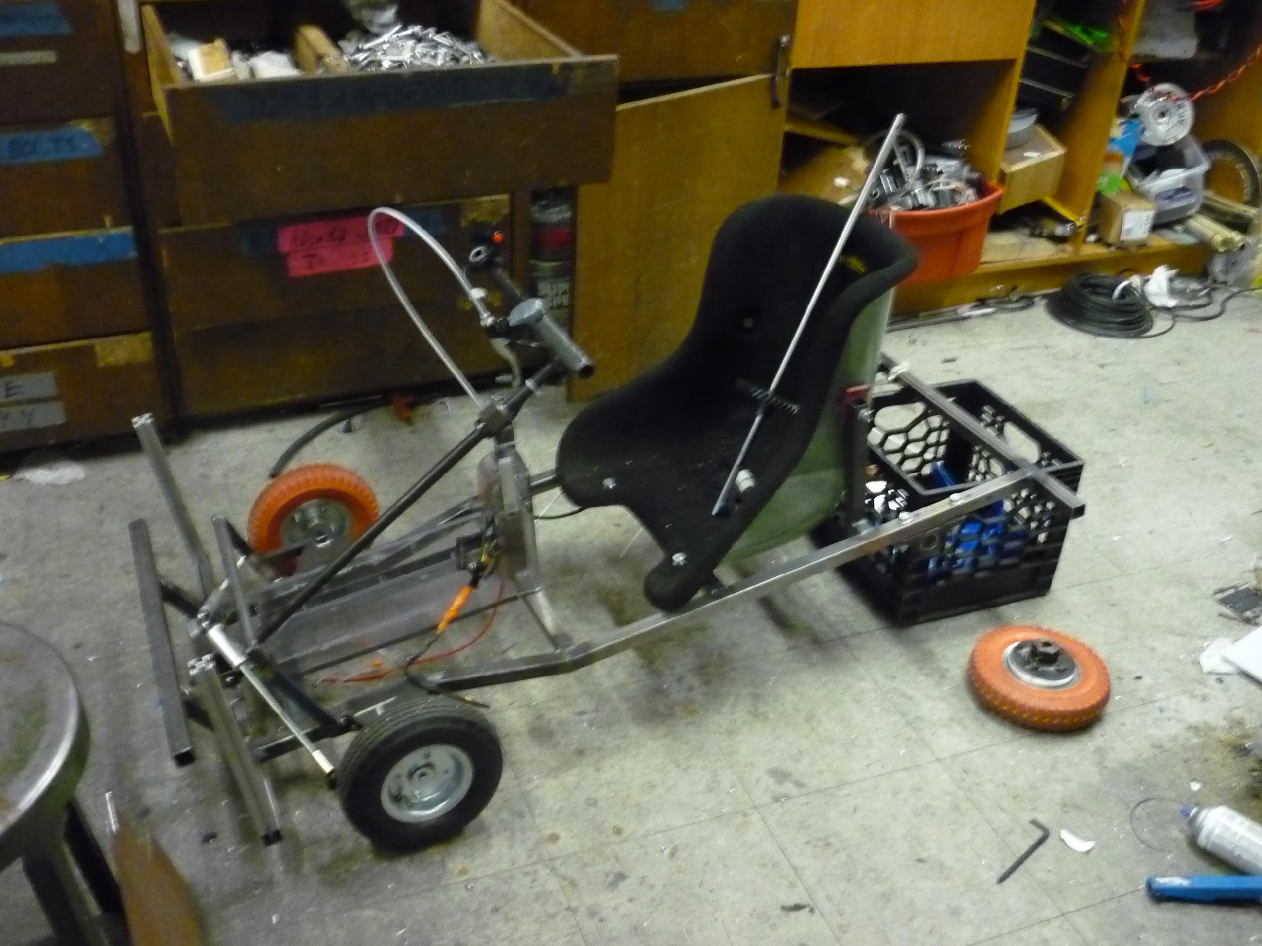
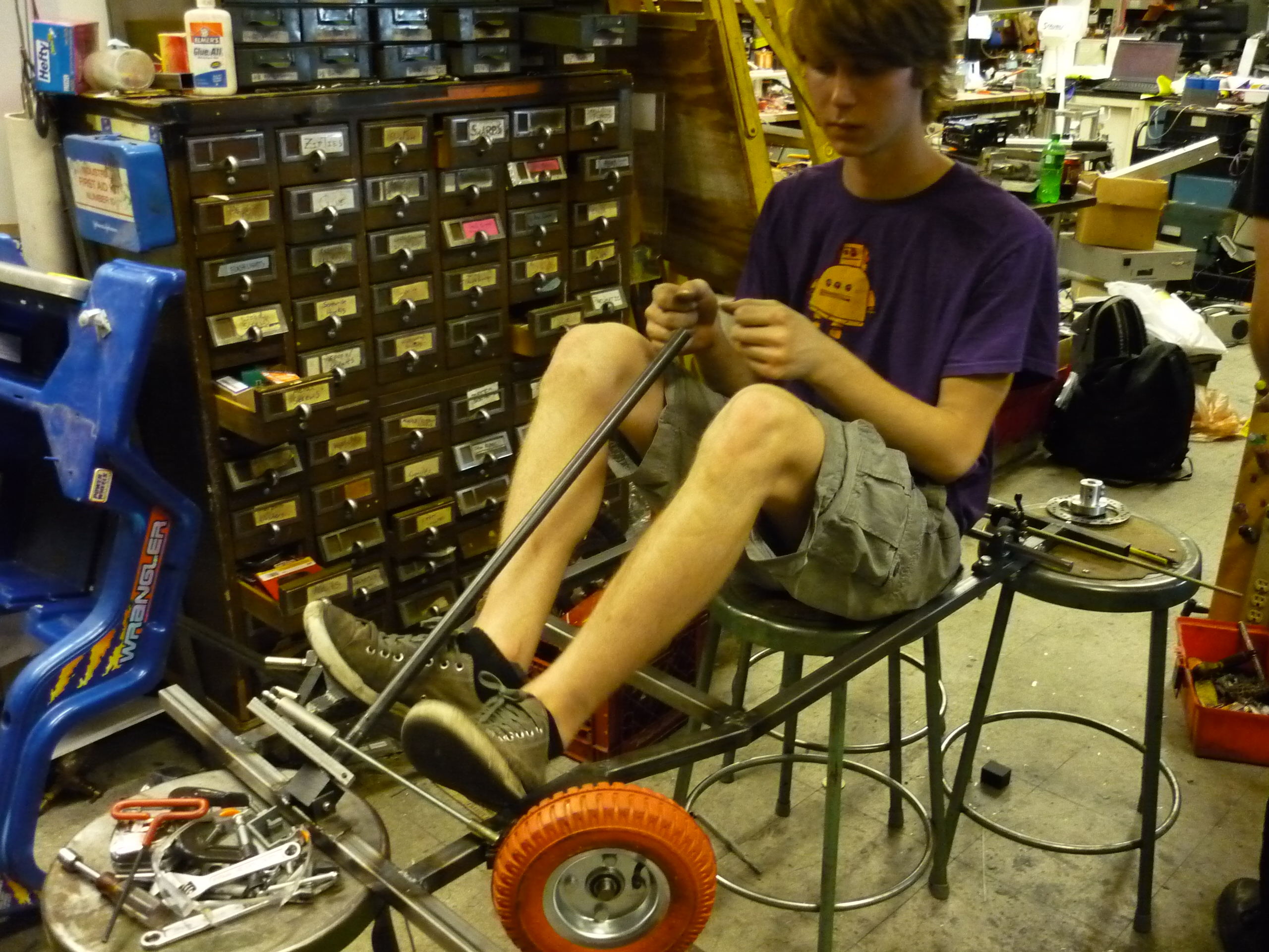
| The frame started as a tack-welded together pile of 1/16th wall 1" square steel tube, measured and modeled using the finest in cad software, chalk drawn around the sawzalled powerwheels frame. | 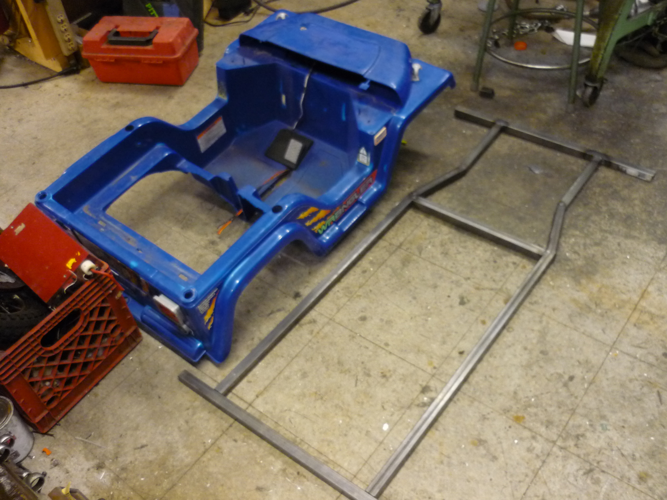 |
 |
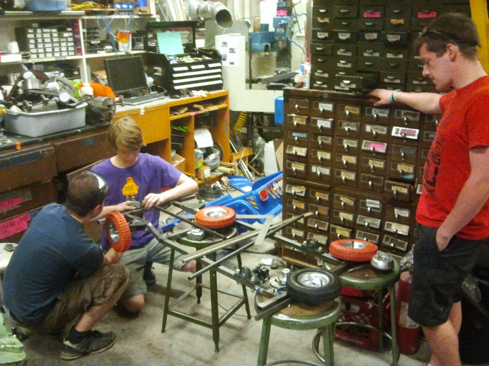
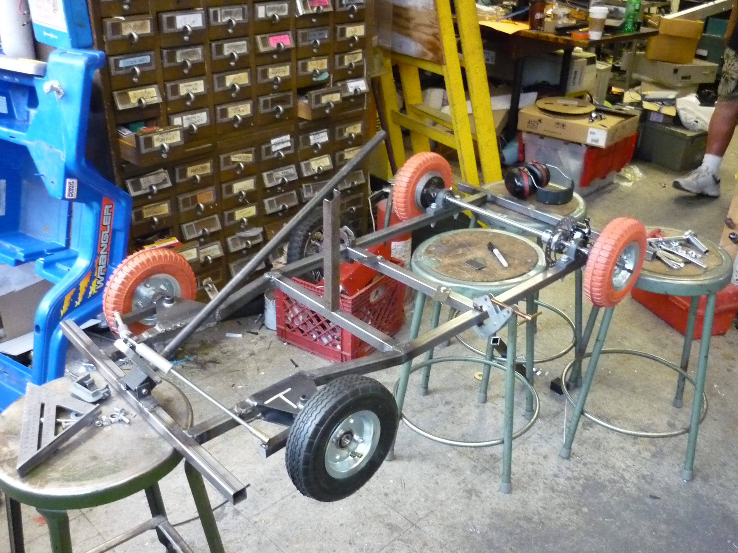
| After rough tack-welding the frame was tig-welded together at the ever-awesome DLAB welding shop. The start of the frame was suprisingly lightweight at this stage, and we opted to hold it up with the only 3 stools in miters that were the same height. | 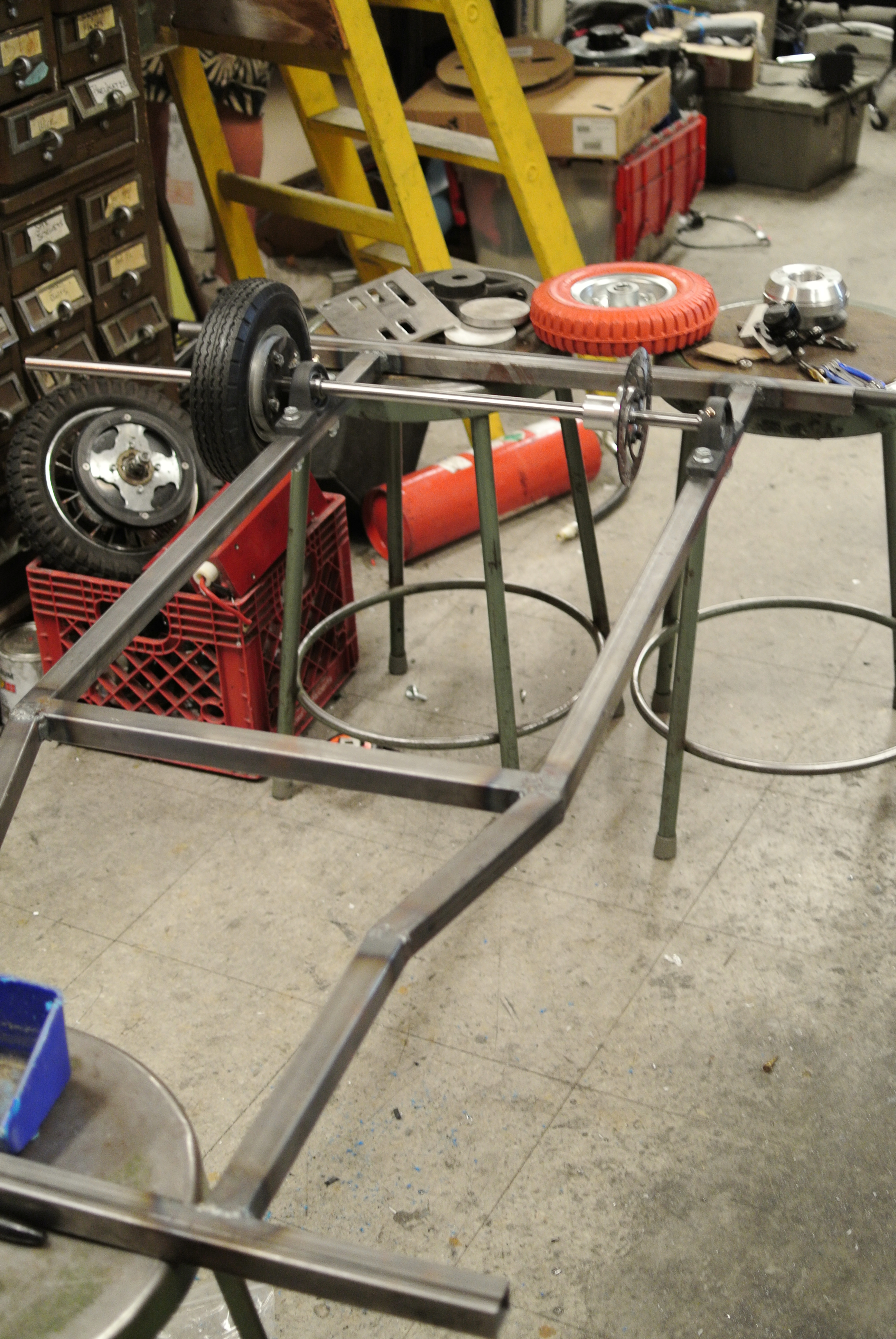 |
 |
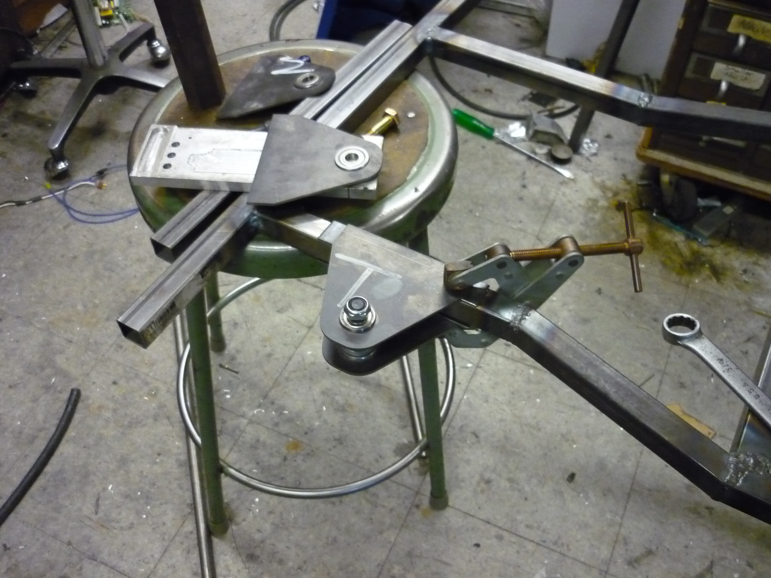
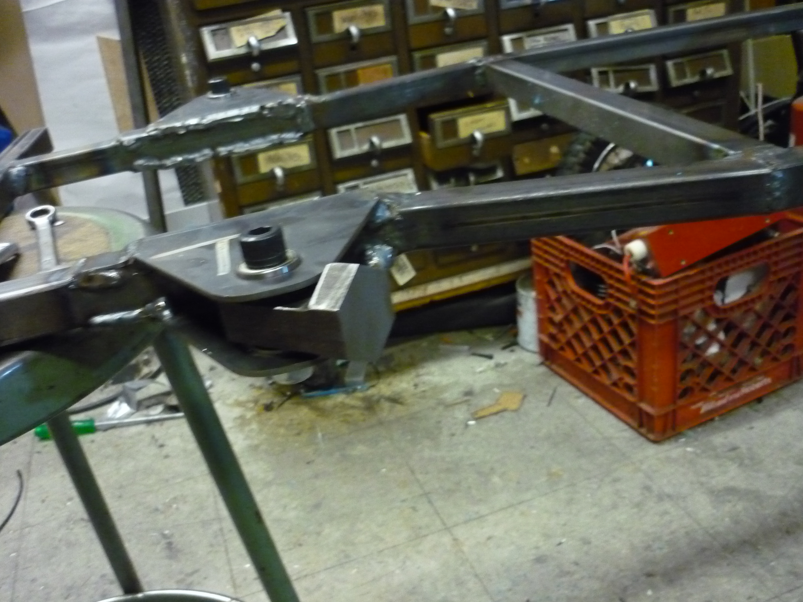
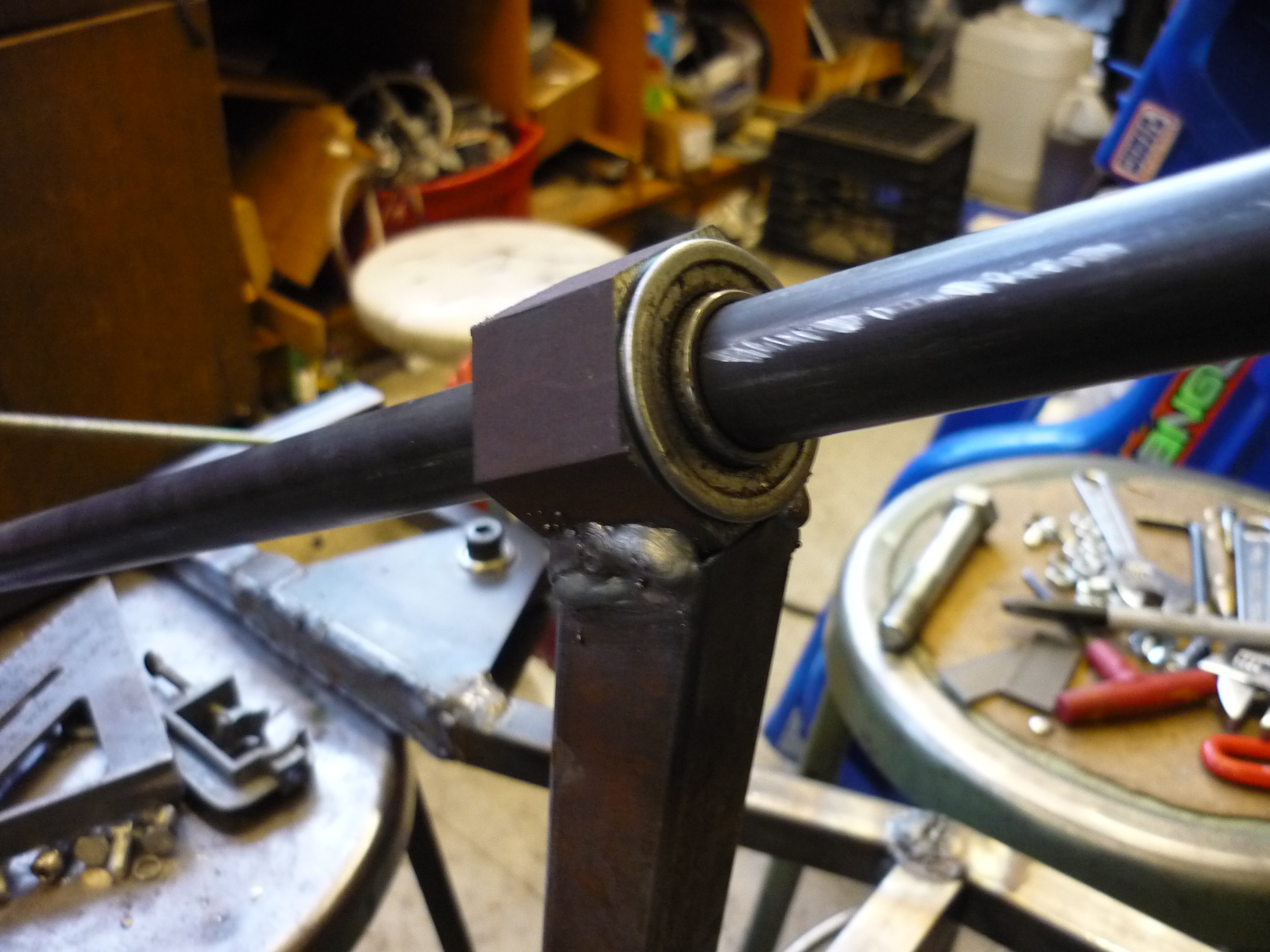
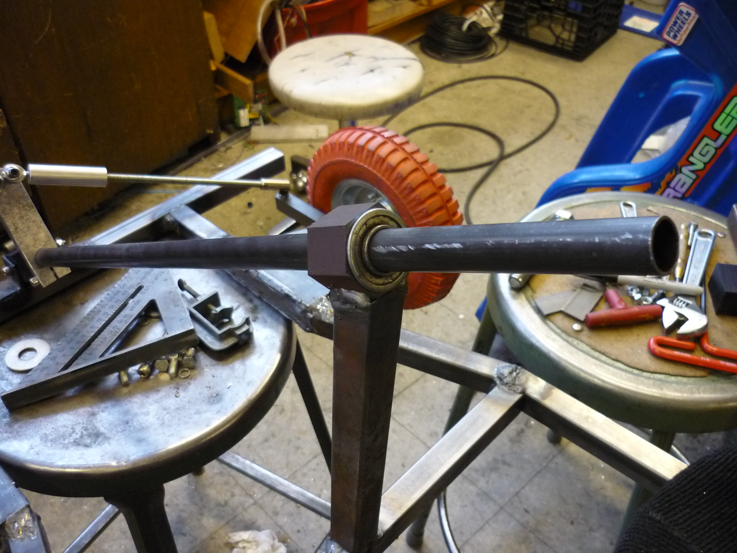
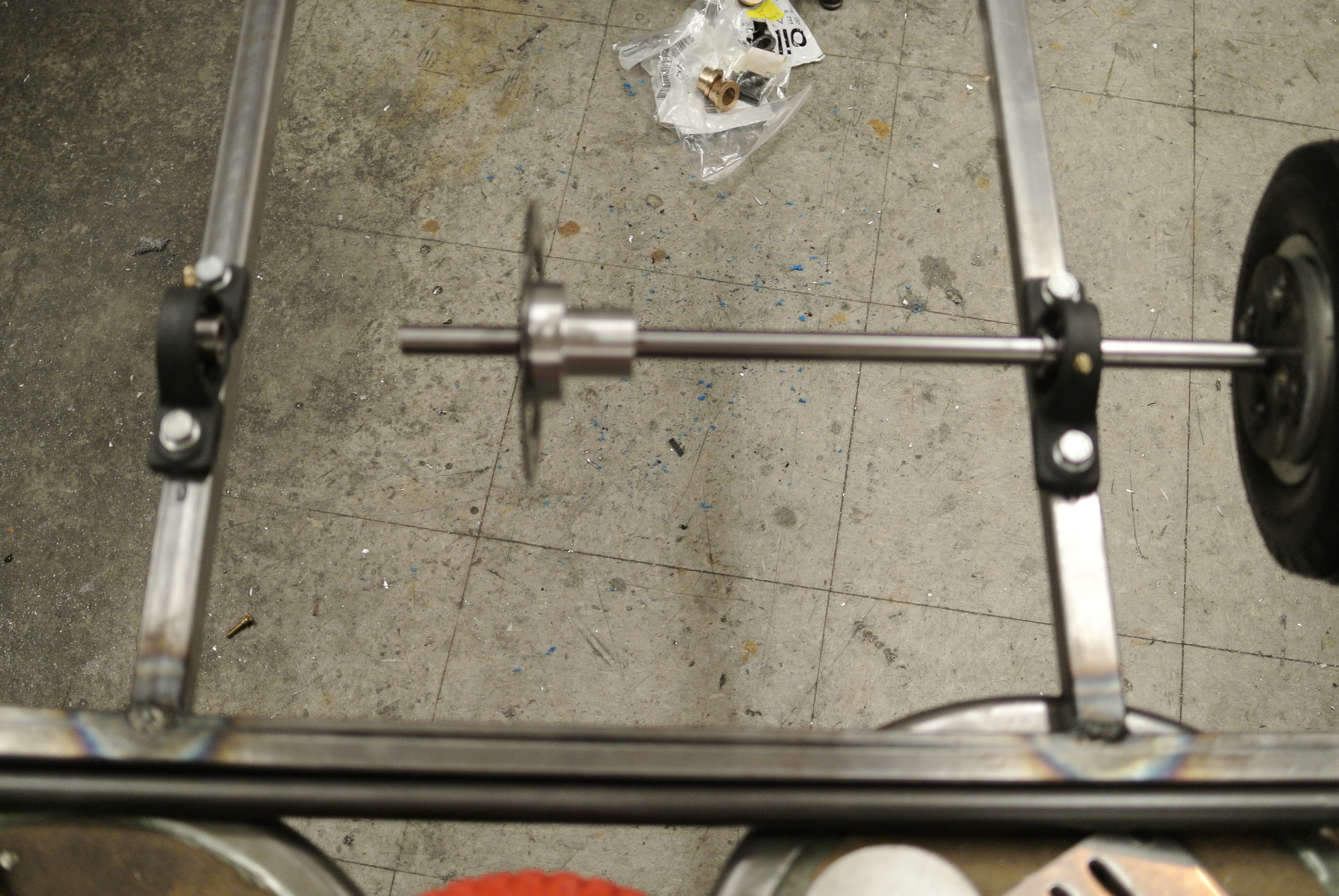
| Pillow
blocks The first thing that was tied to the frame were the two 5/8 ball-bearing pillow blocks. The frame wasnt super-symetrical as there was some incorrect polarity welding wich punched a hole through one of the mating surfaces, so the bearing-shaft assembly lined up with the rear part of the kart. The hardened shaft is shown shining brilliantly. |
 |
 |
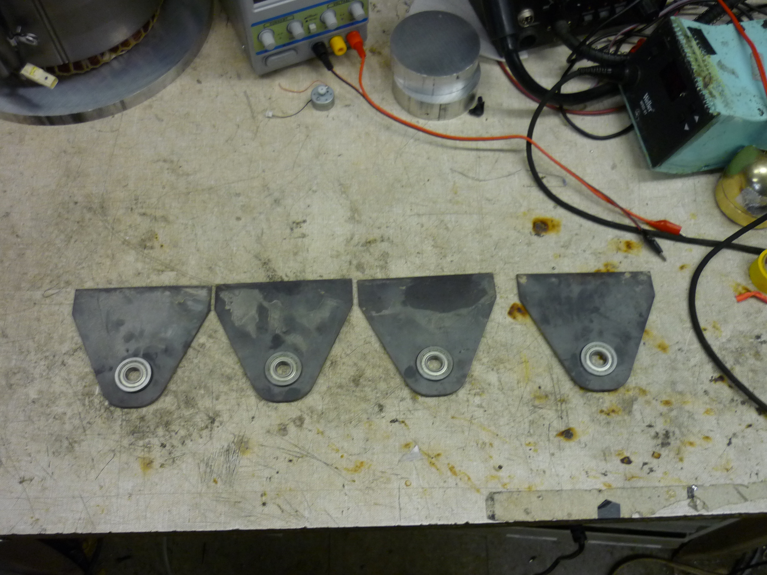
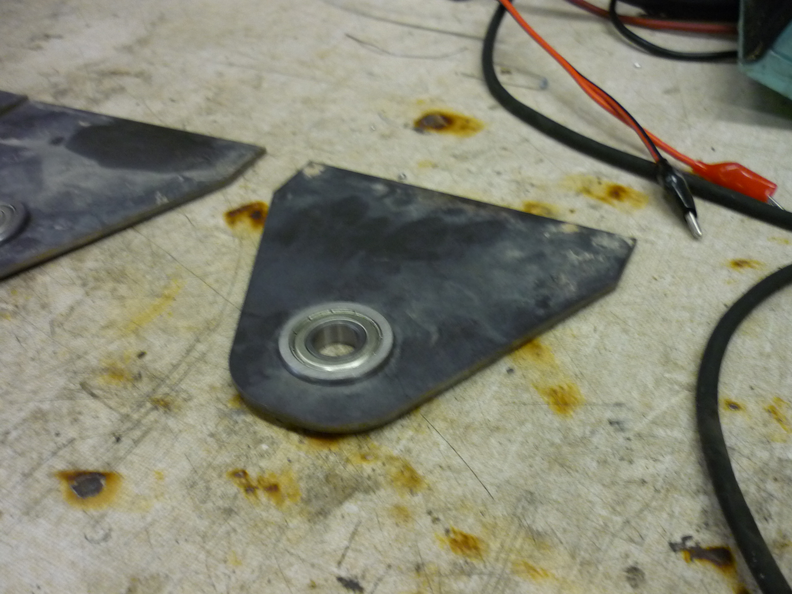
| The
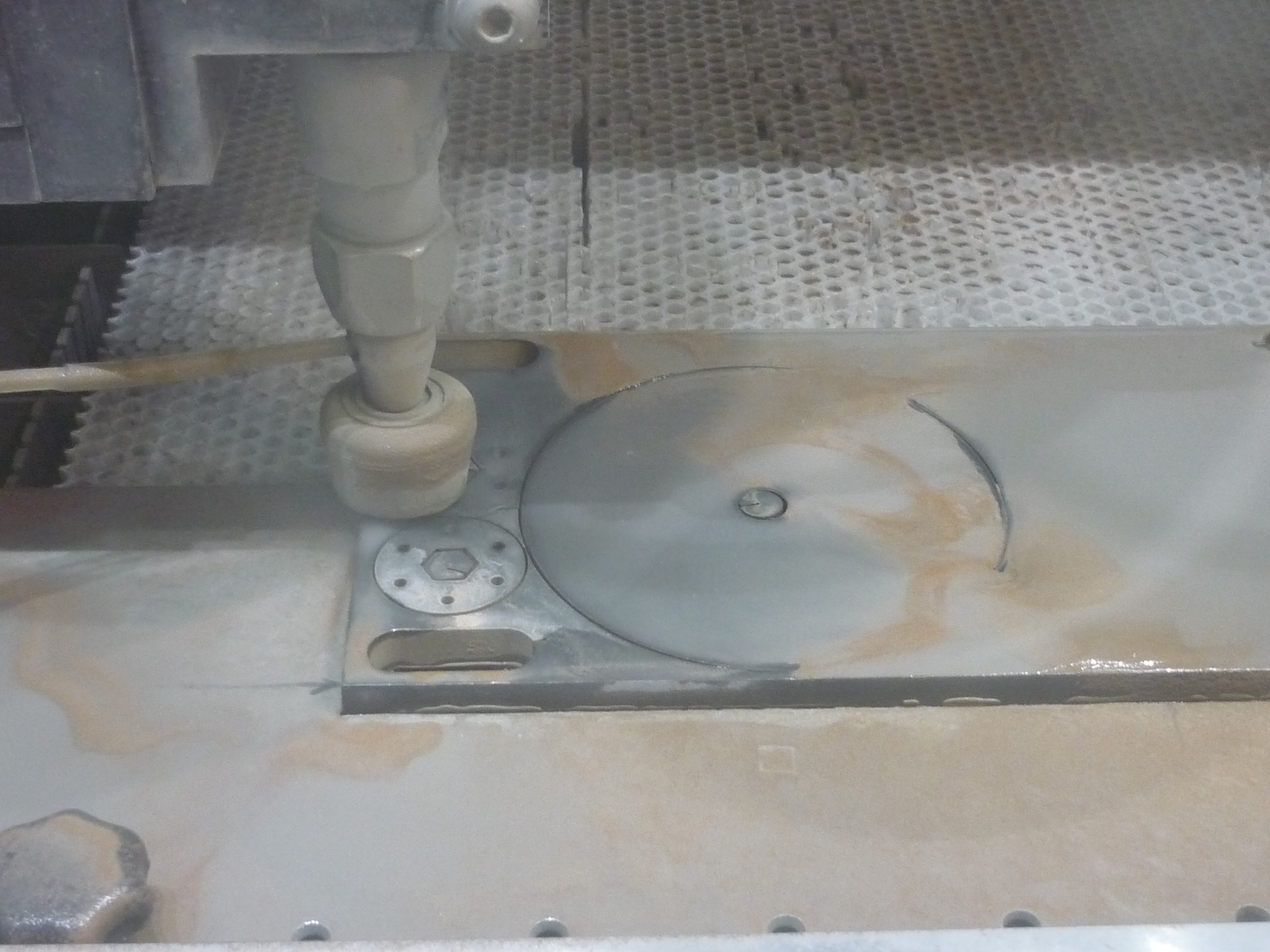
steering of the beast begins A comrade had gifted some 1/8" thick steel plate, way back in battlebot season, during the atomic-bumble-prime build. Having access to a 30 minute block of time on the hobbyshop waterjet, I cut out some haistly made steering bearing holsters. |
 |
 |
| Rough
placing of the steering points Using steel plate as shims, the steering bearing blocks were positoned and migged in place. A slaughter-fest of mig-fueled gloriousness occured, with the bearings in place, clamps keeping everything tight and an allignment bolt holding everything true. |
 |
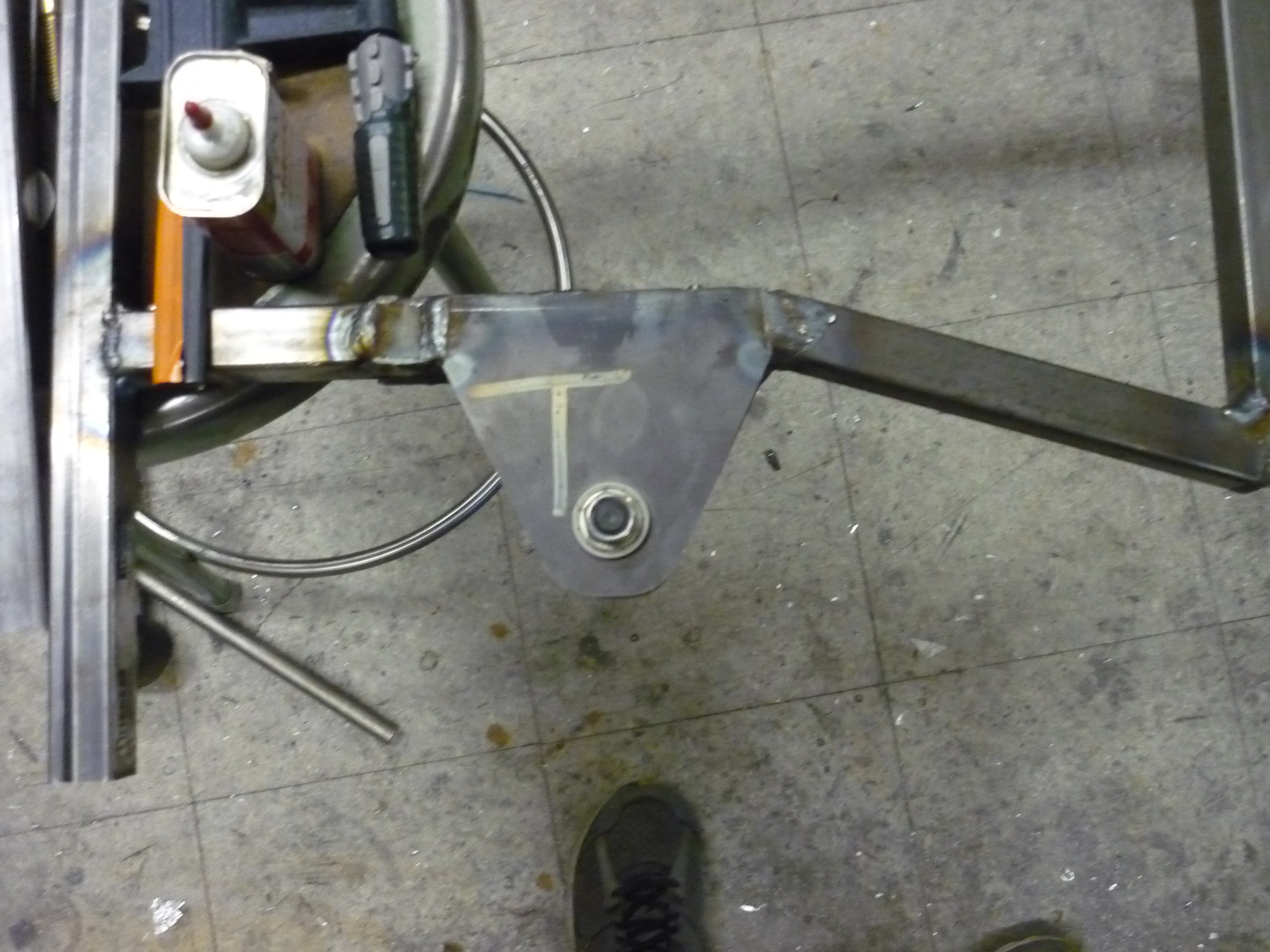 |
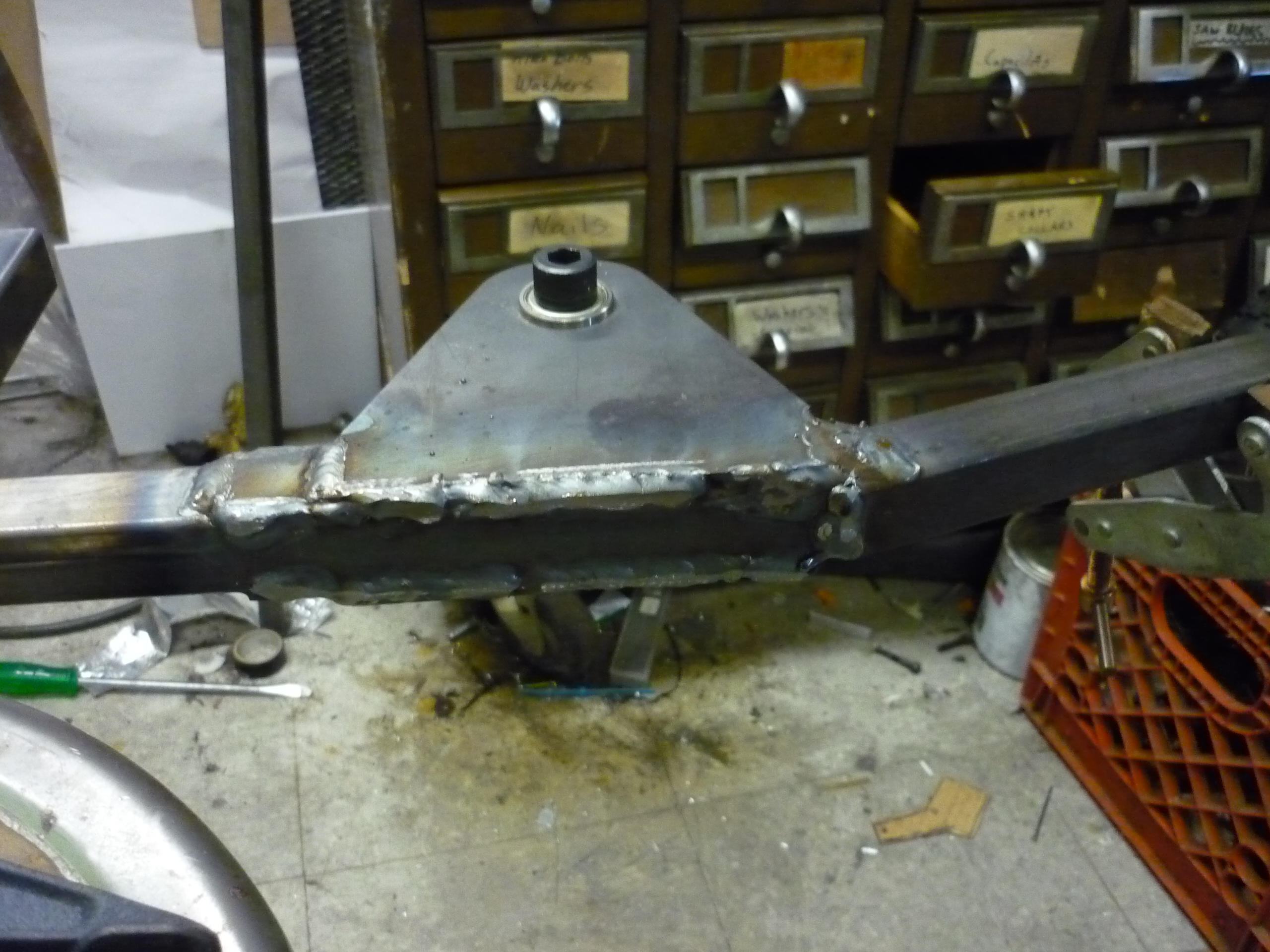
| Welding
ahoy Yeah that was a lot of weld. As these were flanged bearings, with the center barstock on the center preventing lateral motion of the bearings. |
 |
 |
| Hexagonal
steel barstock to the rescue A scrap hexagonal barstock was used as the nating between the steering pivot point and the soon to be steering axle. This worked excellently as, later-on, boring the press-fit mount for the steering axle became easy, as the hexagonal rod fit nicely in the lathes' three jaw chuck. |
 |
 |
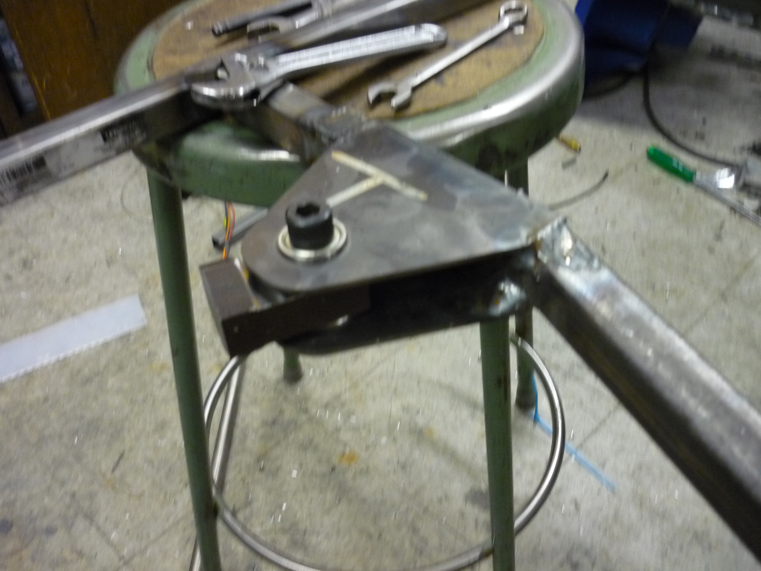
| Toying
with steering geometery There was some back and forth (PUN INTENDED) for the placement and angle of the steering. |
 |
 |
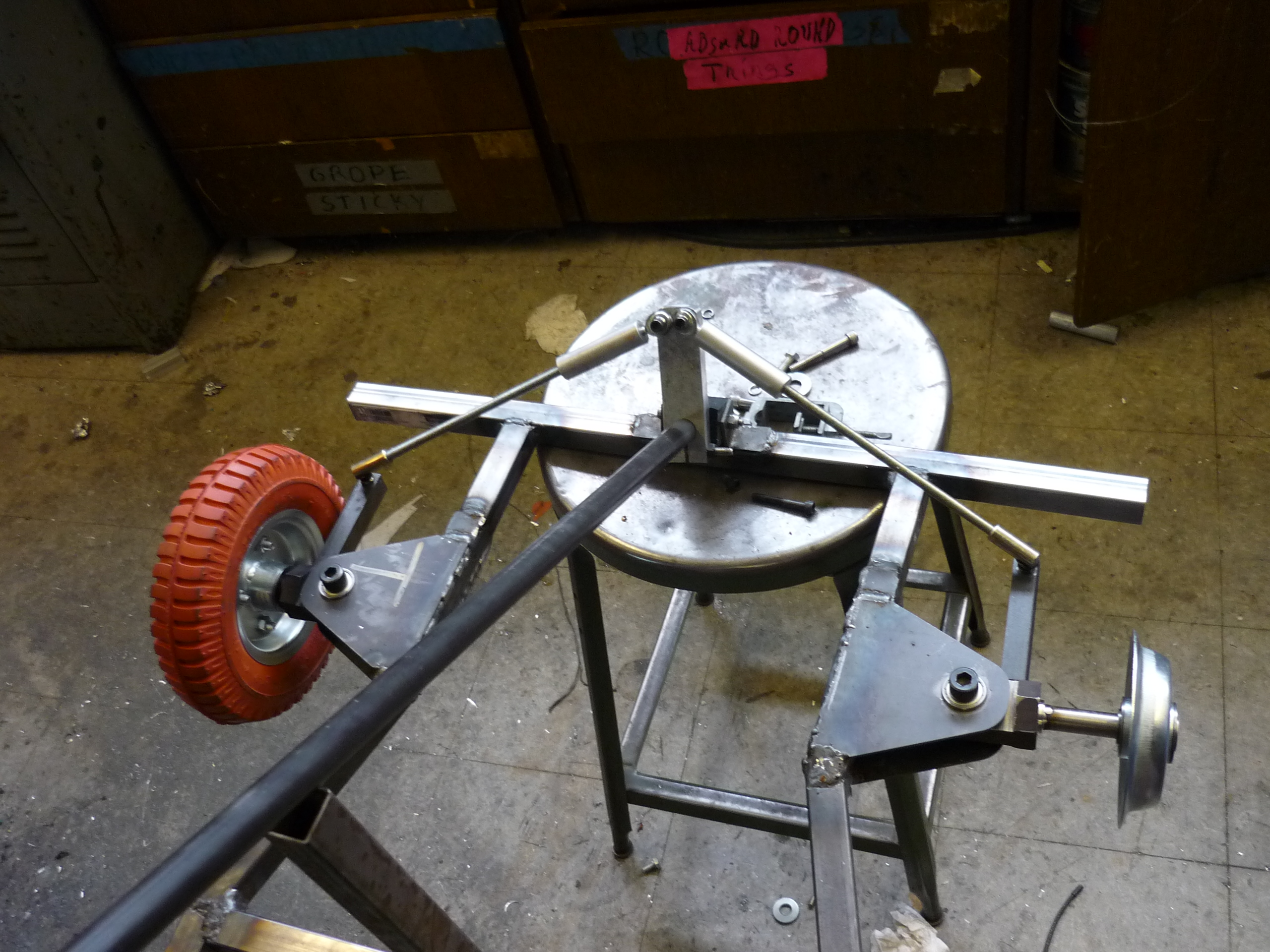
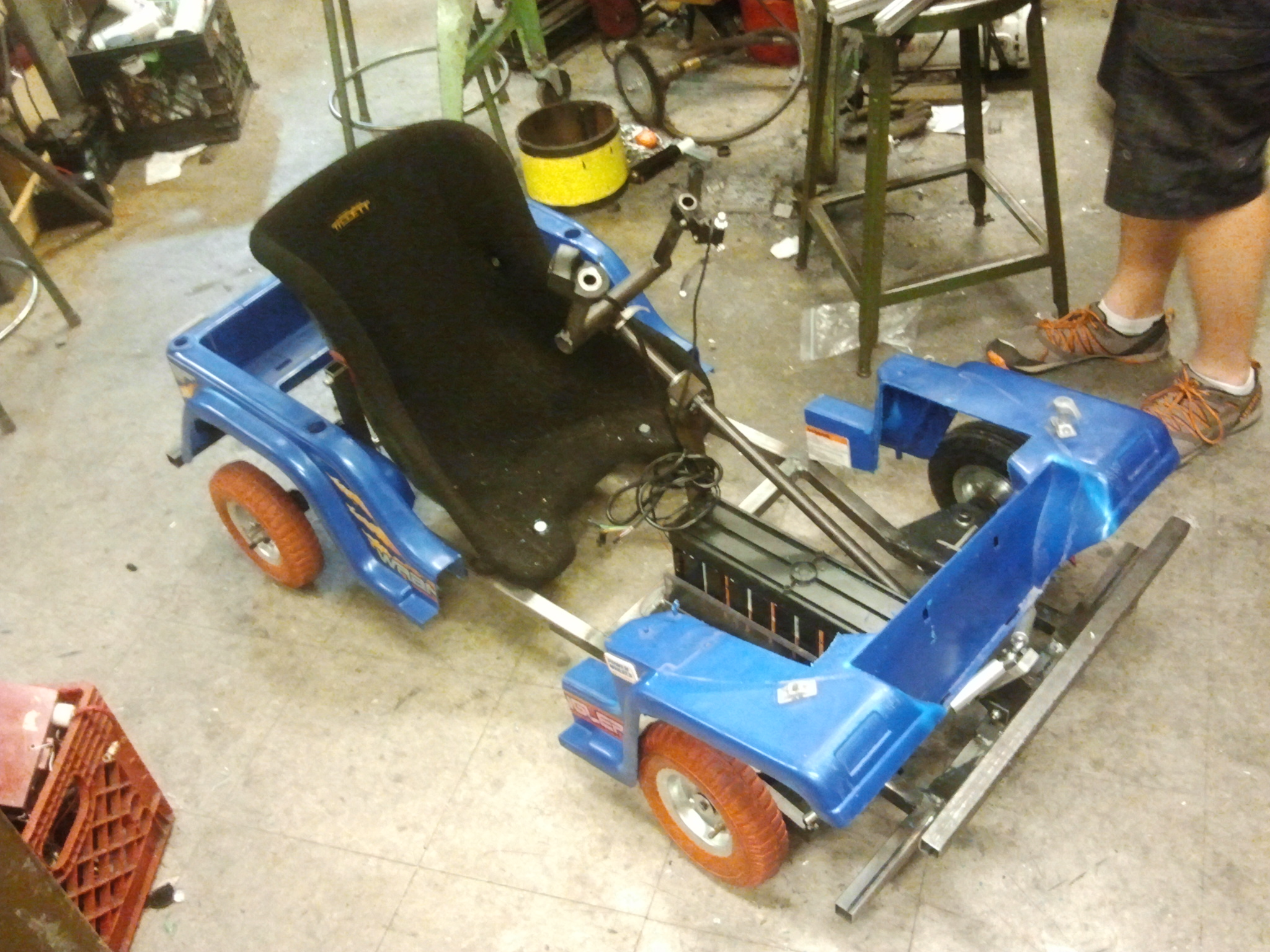
| Steering
geometry There was a narrow mishap here, as the kart almost had reveresed steering, fortunatley, with the a-arms tigged in place and the ball-mounted steering linkages, everything lined up. OH! we also inherited a seat from Shane colton's Cap-Kart. THANKS SHANE! |
 |
 |
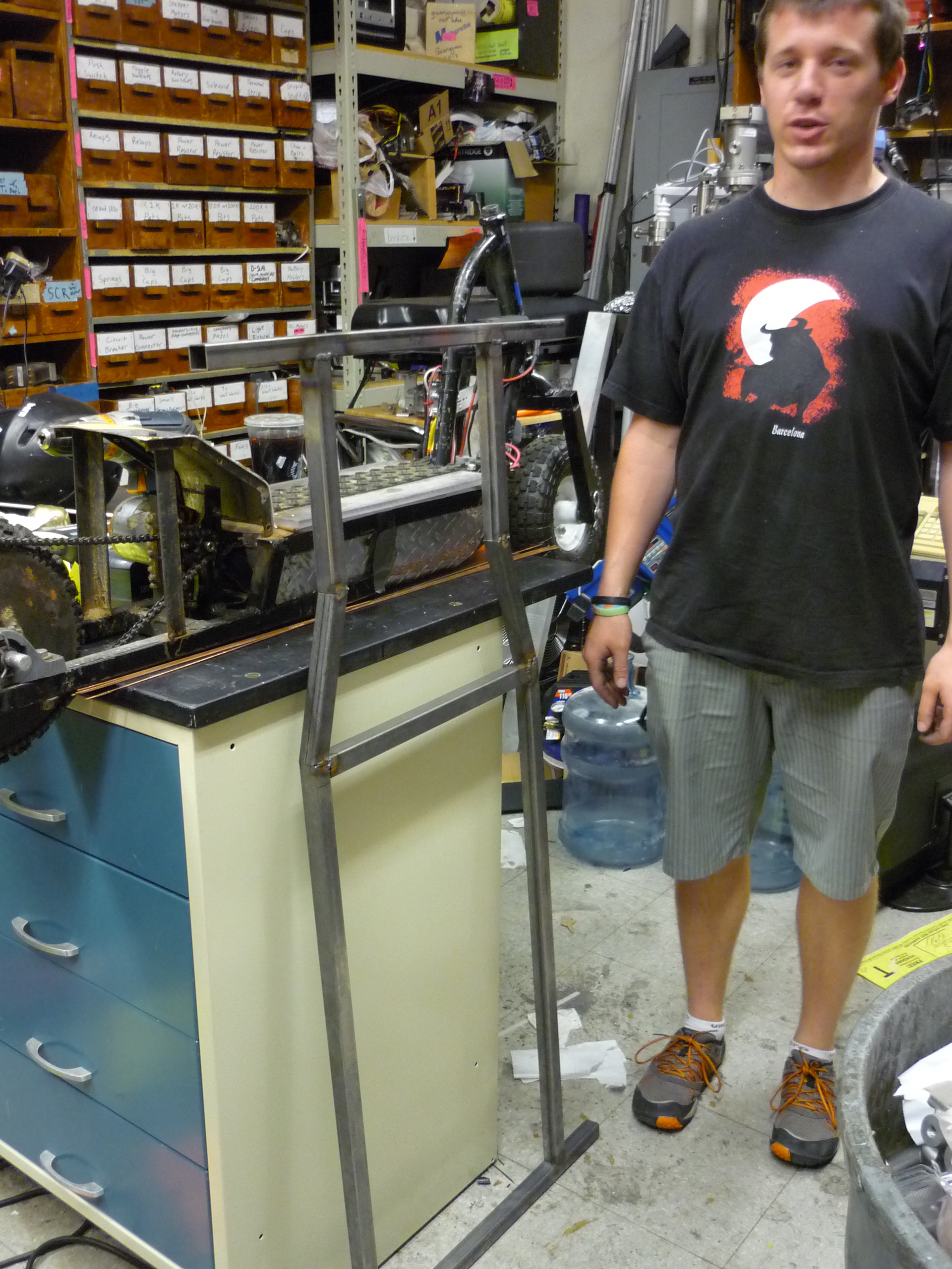
| Steering
rod and upright After some rough placement the steering column and seat, we tack welded everythig in place and began setting up the steering support hardware. |
 |
 |
| Pressing
in a bearing and more Hex stock With the position of the steering column mostly finalized, a hex-stock holster and bearing were added to the upright steering arm. As there's a significant potential for torsion here, copious amounts of weld were added. |
 |
 |
| The
base of the steering I thought this was brilliant, its a happy scrap block of delrin acting as a friction fit for the base of the steering column. Its constrained above by a shaft collar, and tacked in place with some angle iron. |
 |
 |
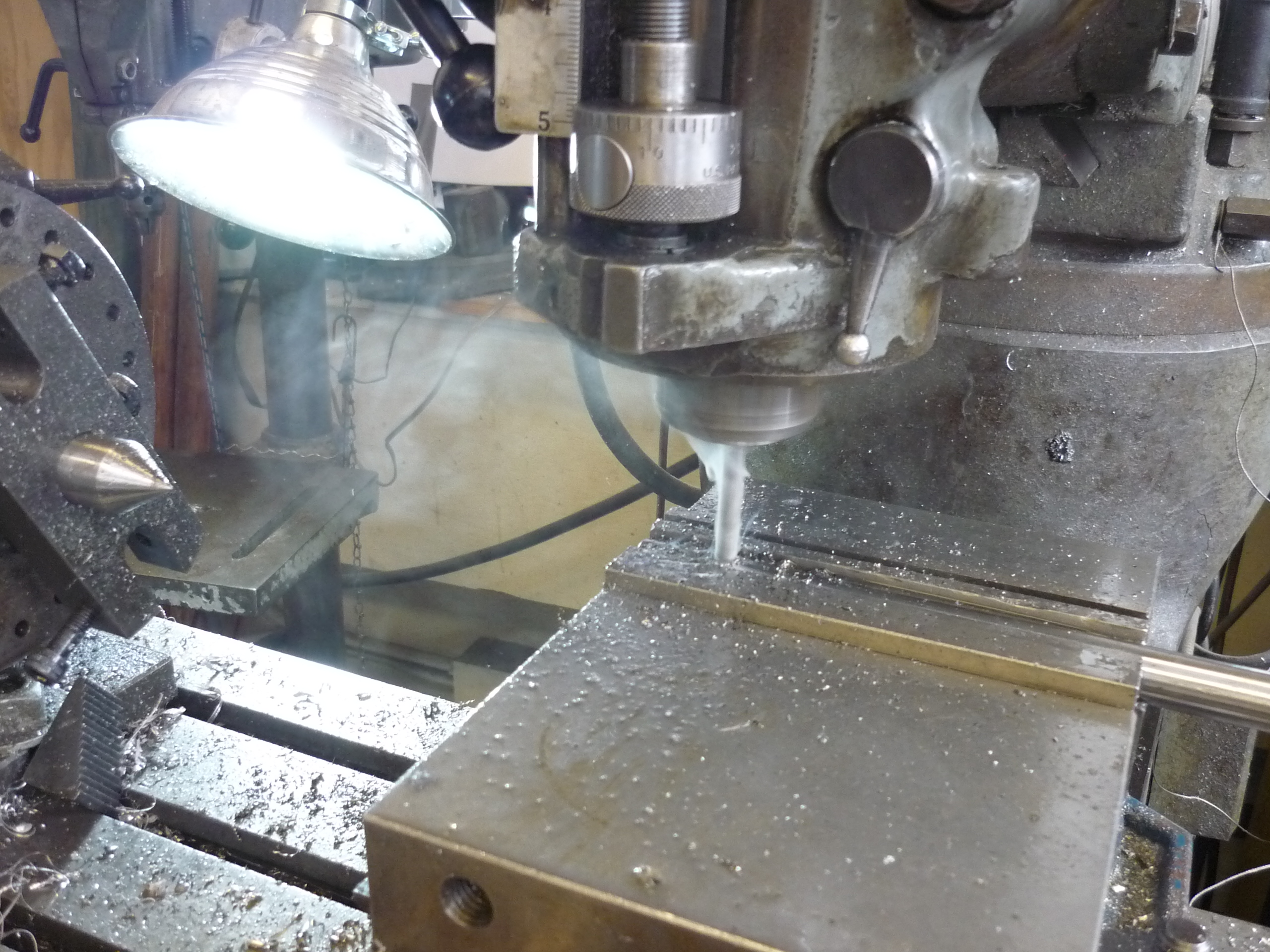
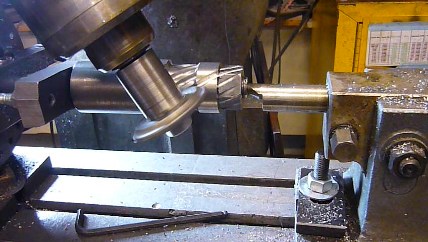
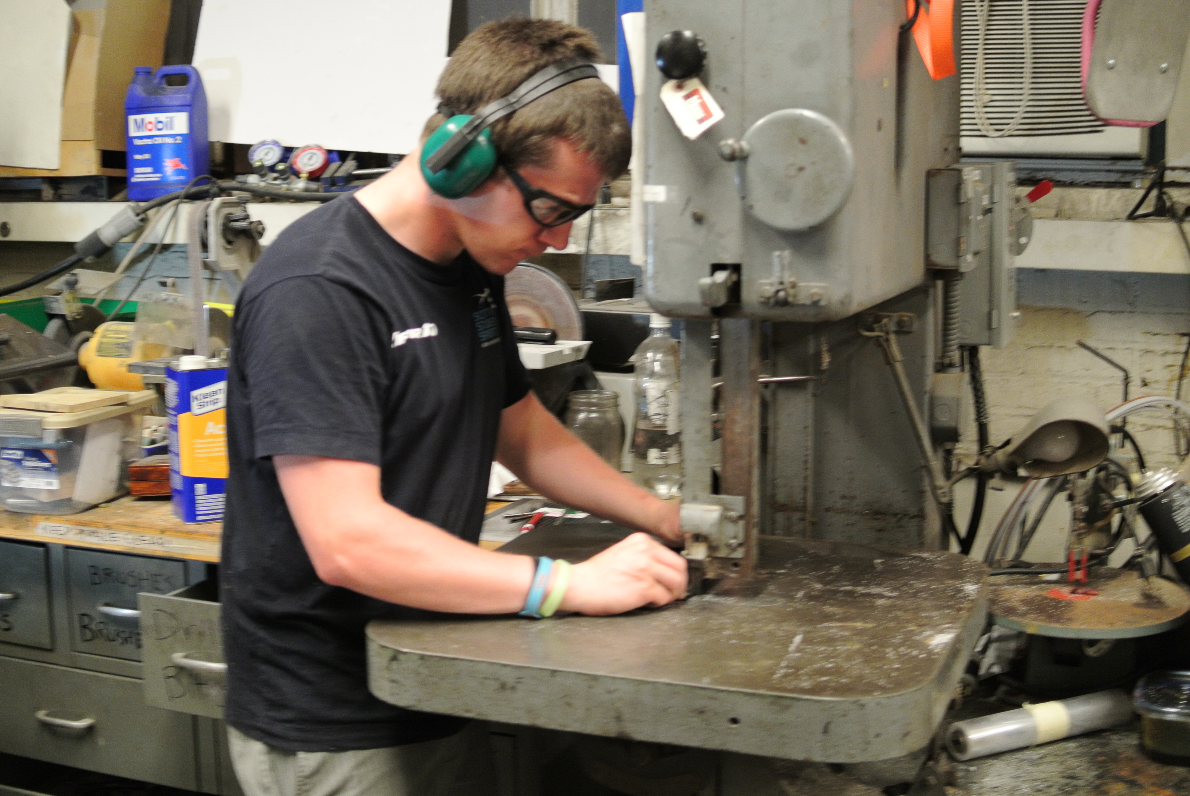
| I purchased a hardened 5/8 shaft for the rear axle, without a built-in keyway. Adding a keyway to a hardened shaft is, at best, time consuming. After burning through a 3/16th carbide bit, Nick Kirkby saved the day with a 1/4" carbide endmill. After a couple dozen passes, a 1/8" deep keyway was born. | 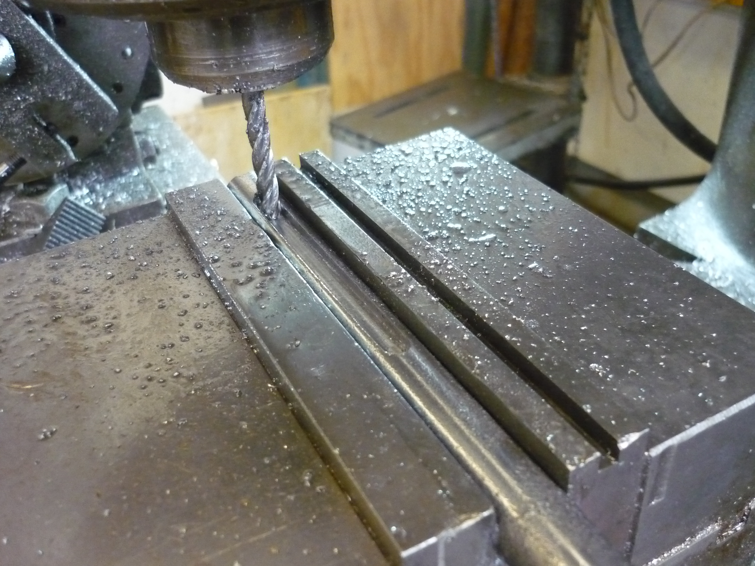 |
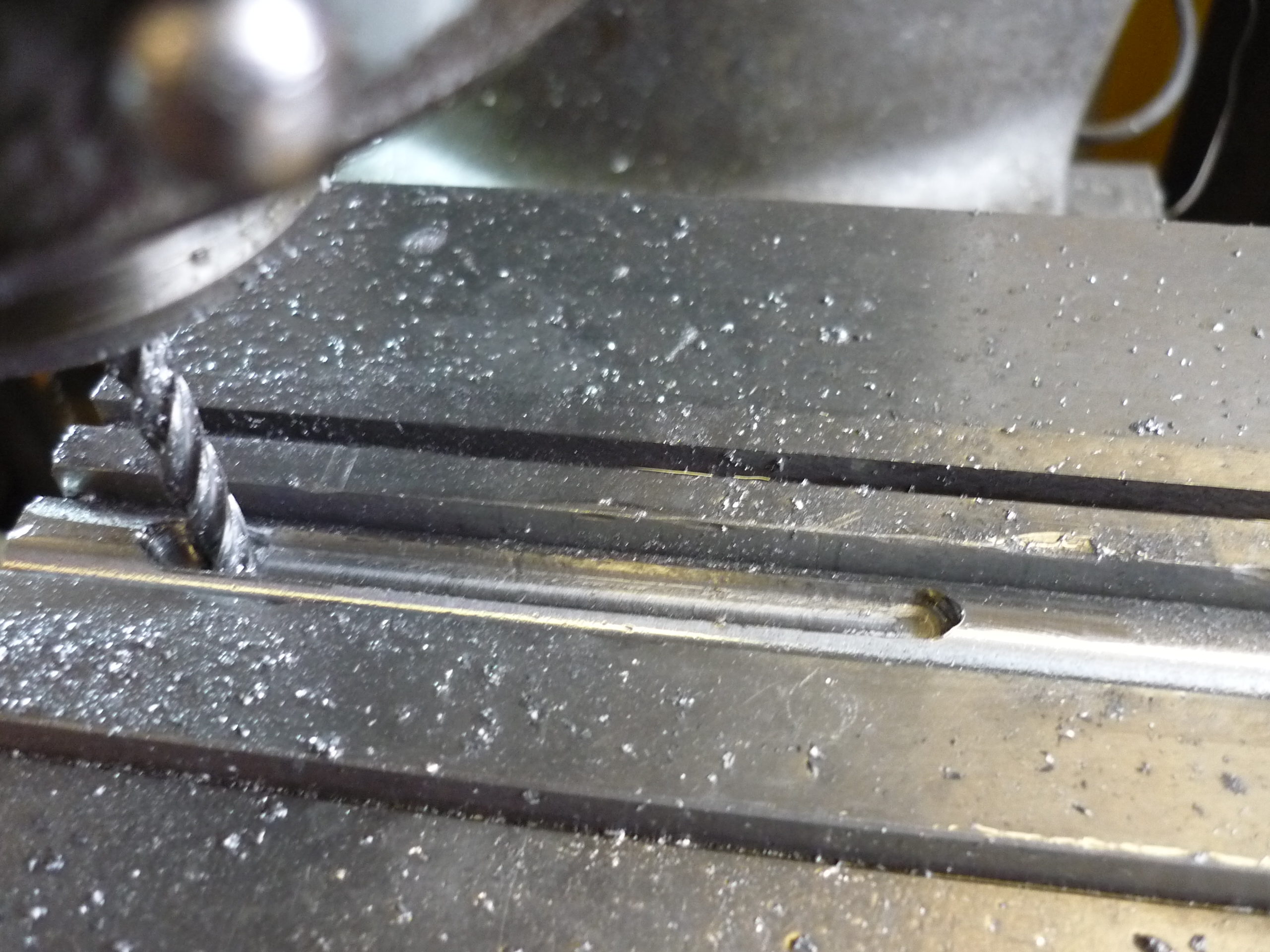 |
| Keyway was required for both tires, and the working end was clamped in the mill-vice. I ended up adding a small fan to blow away coolant vapor and sprayed compressed aire in to keep the tiny chips from being re-ground. | 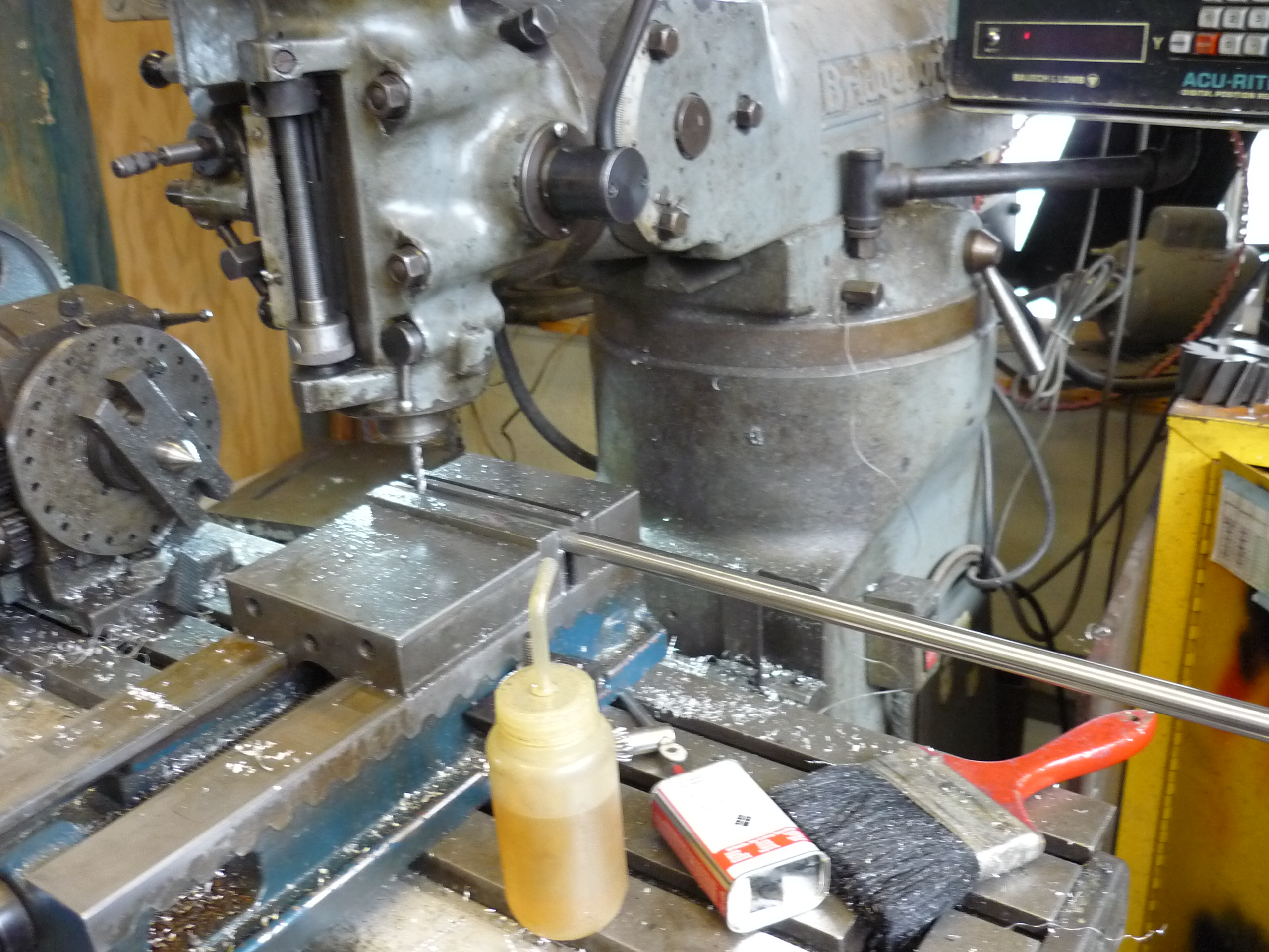 |
 |
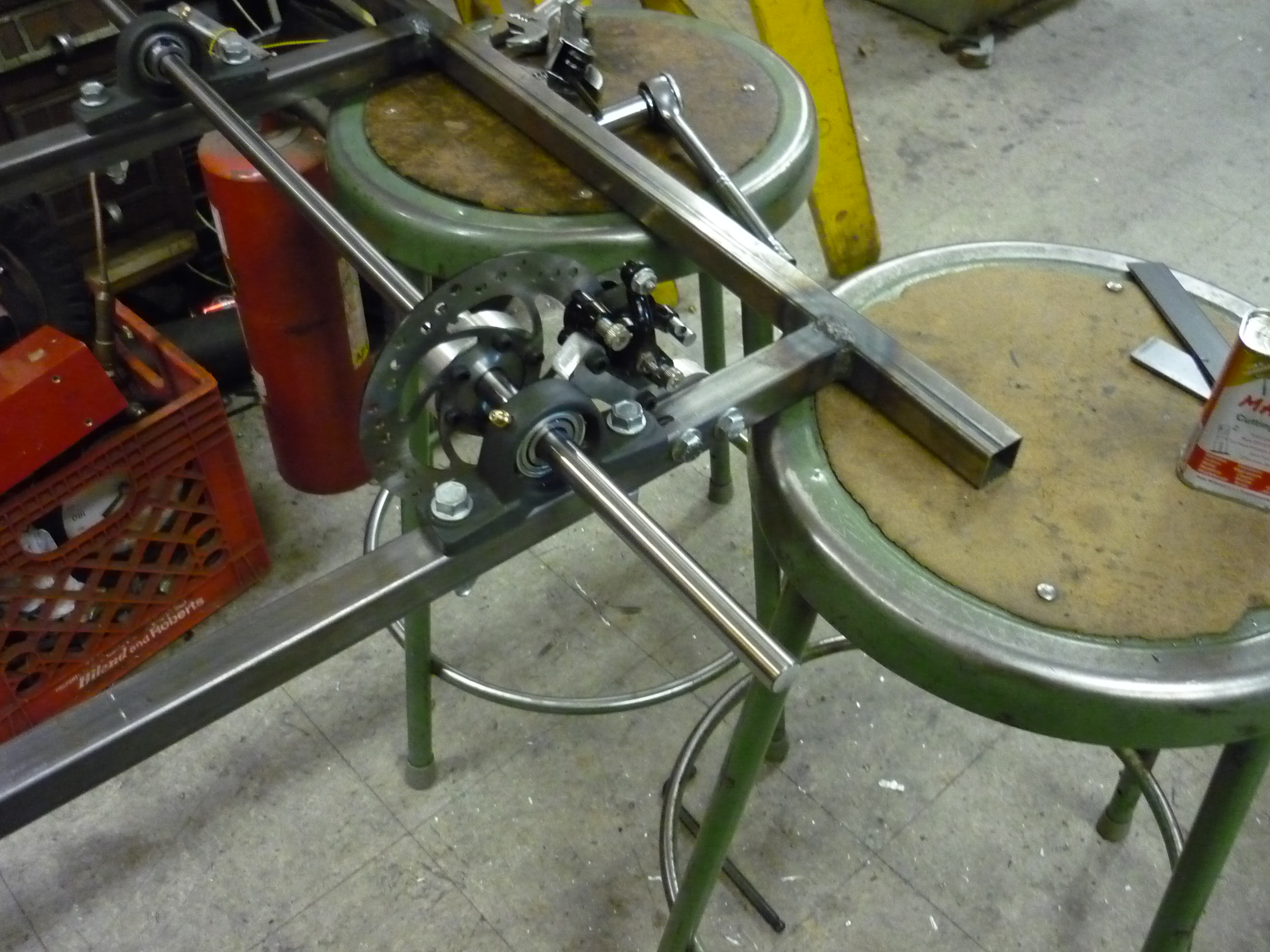
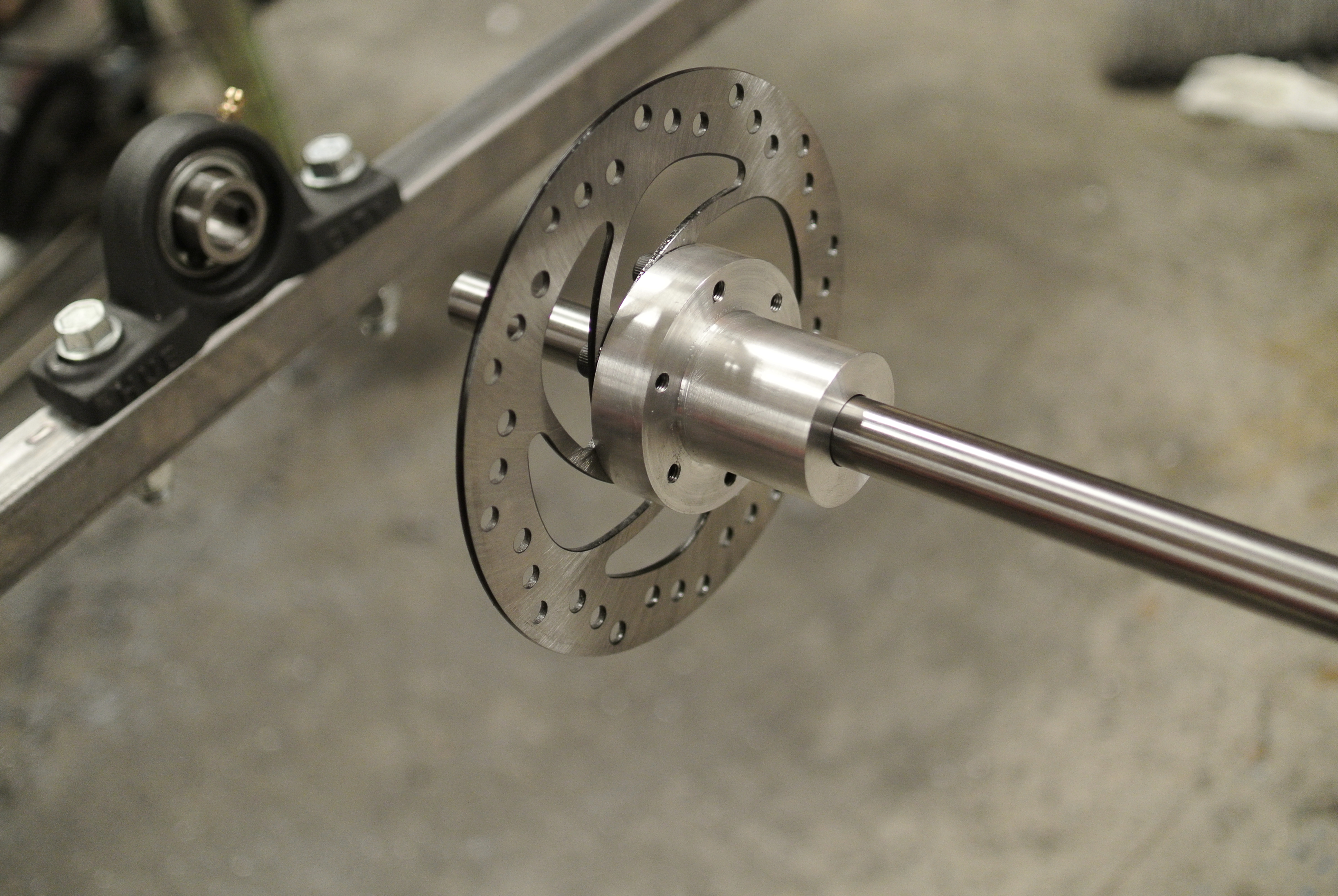
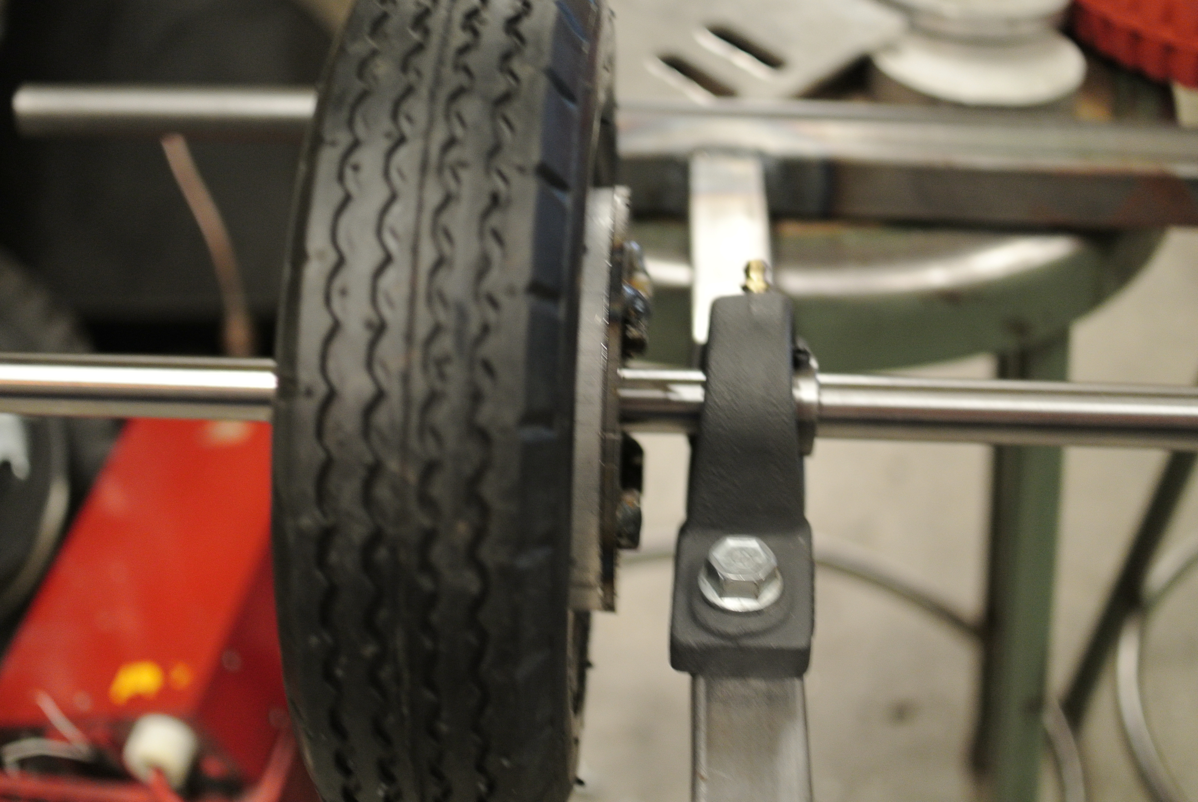
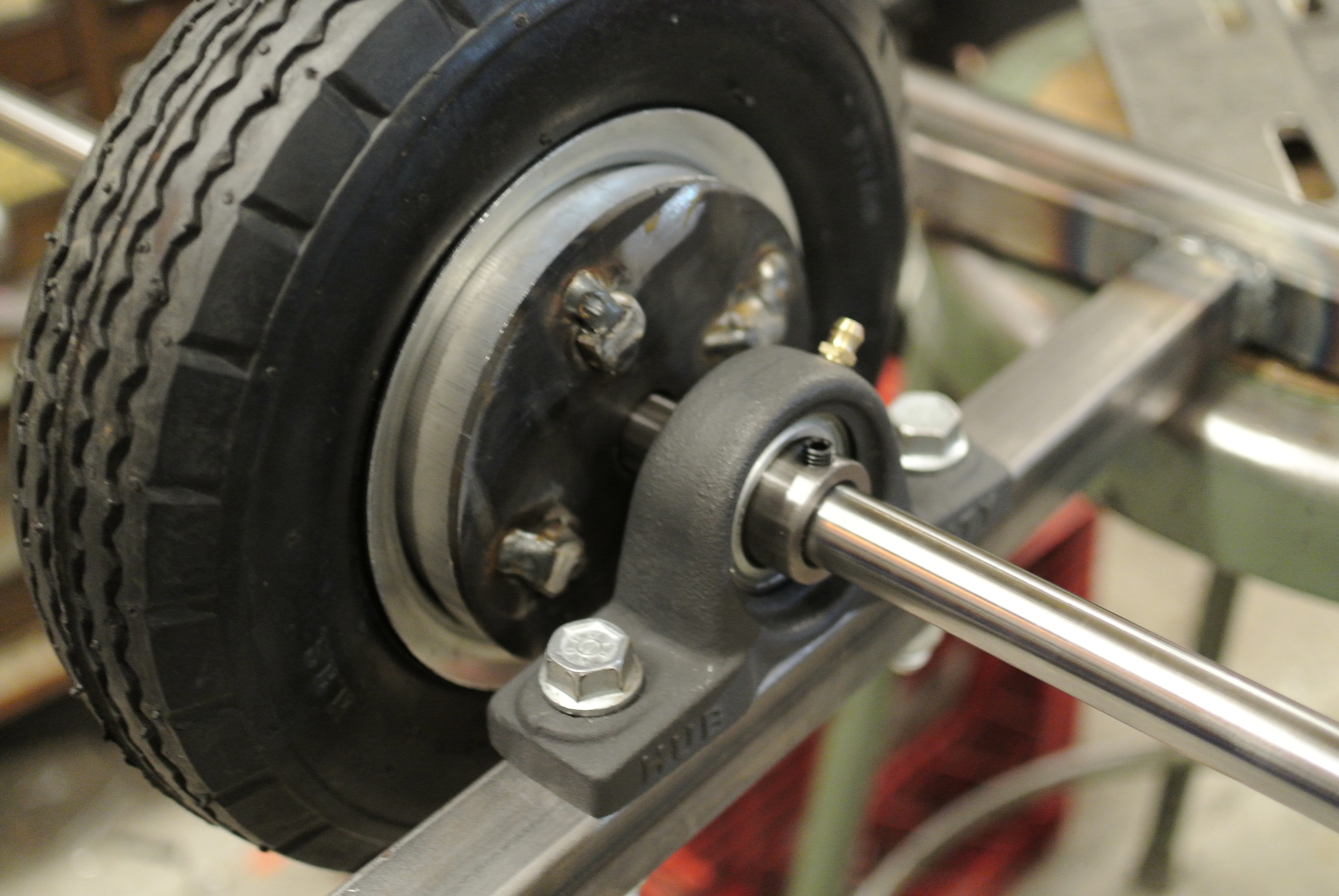
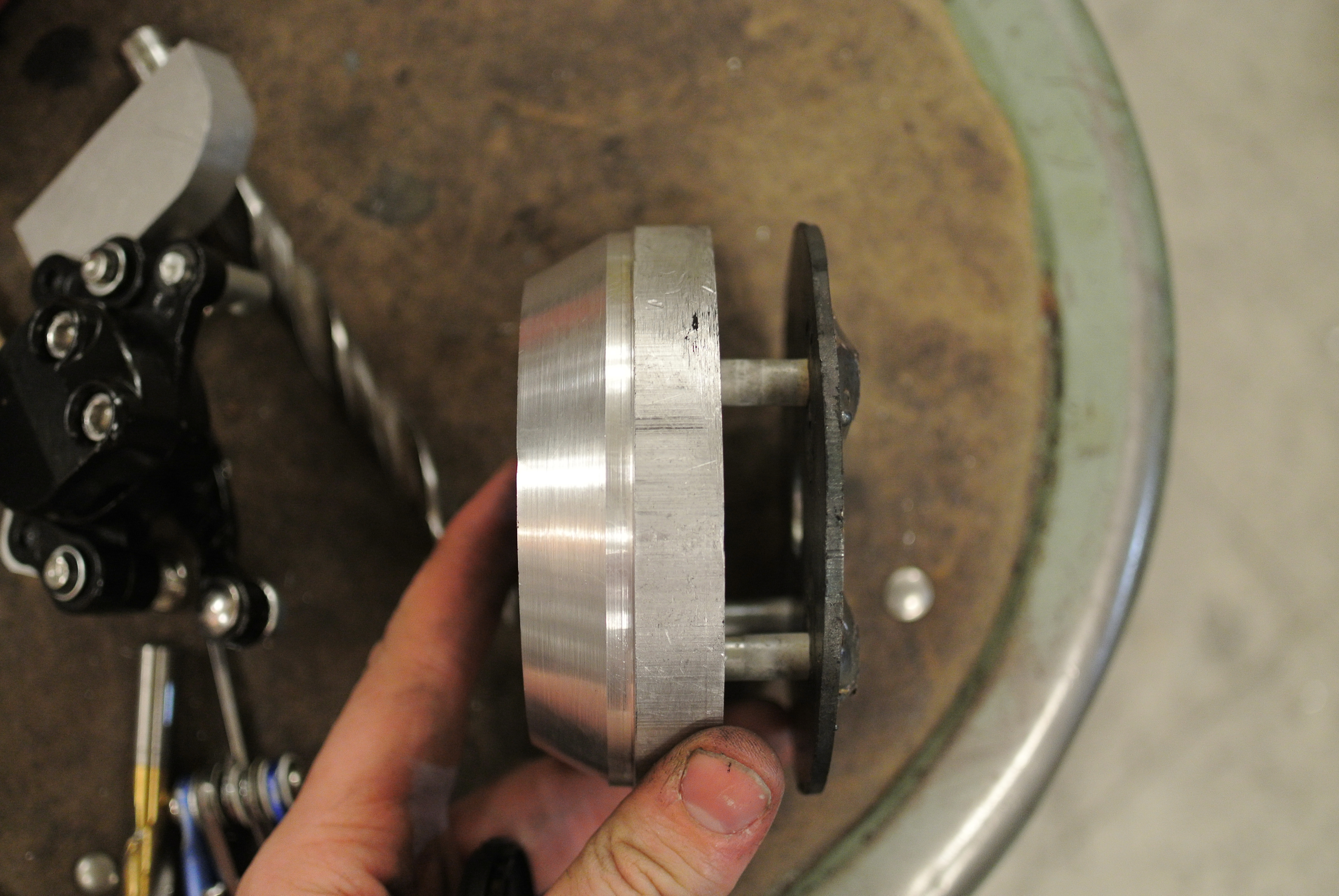
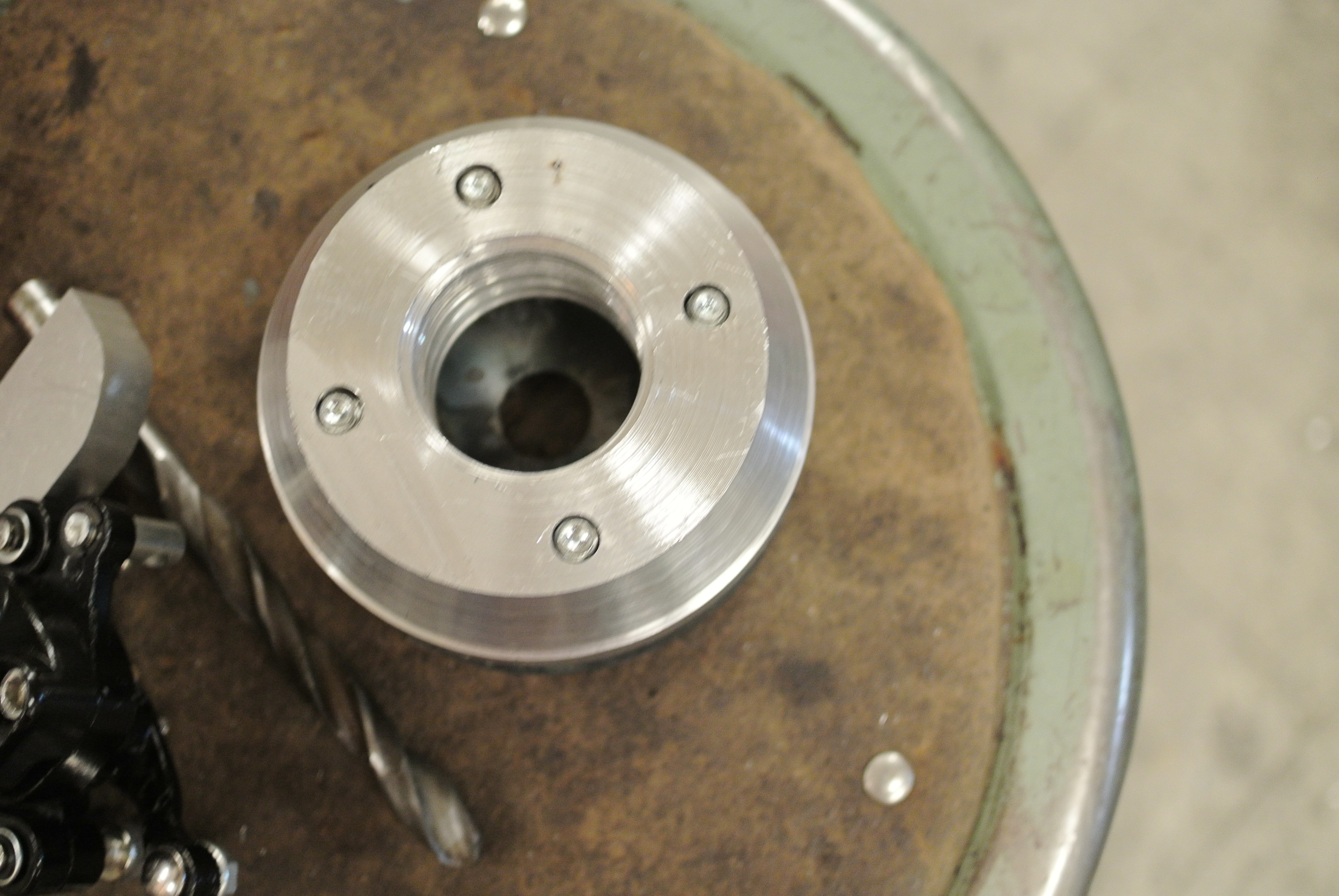
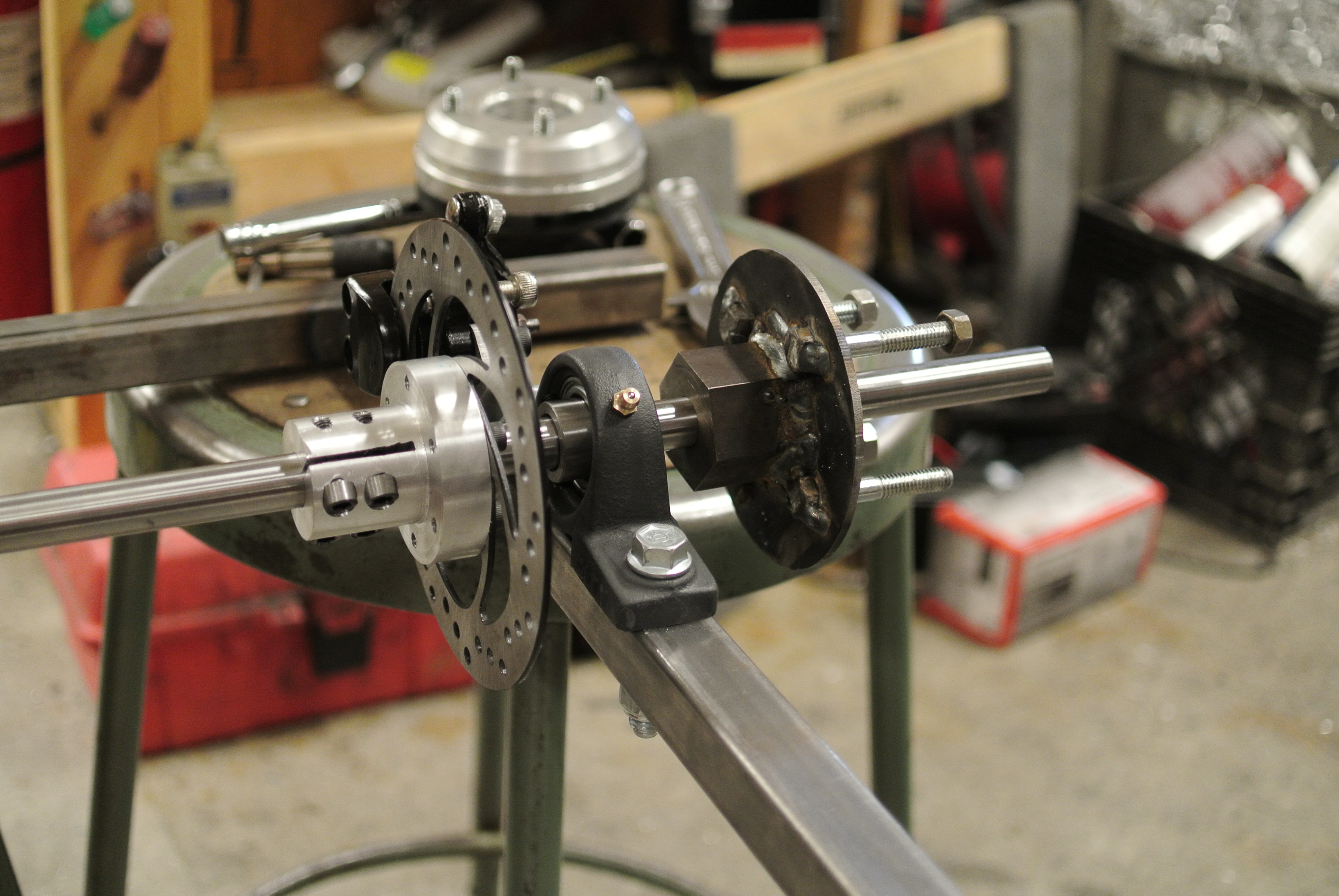
| A
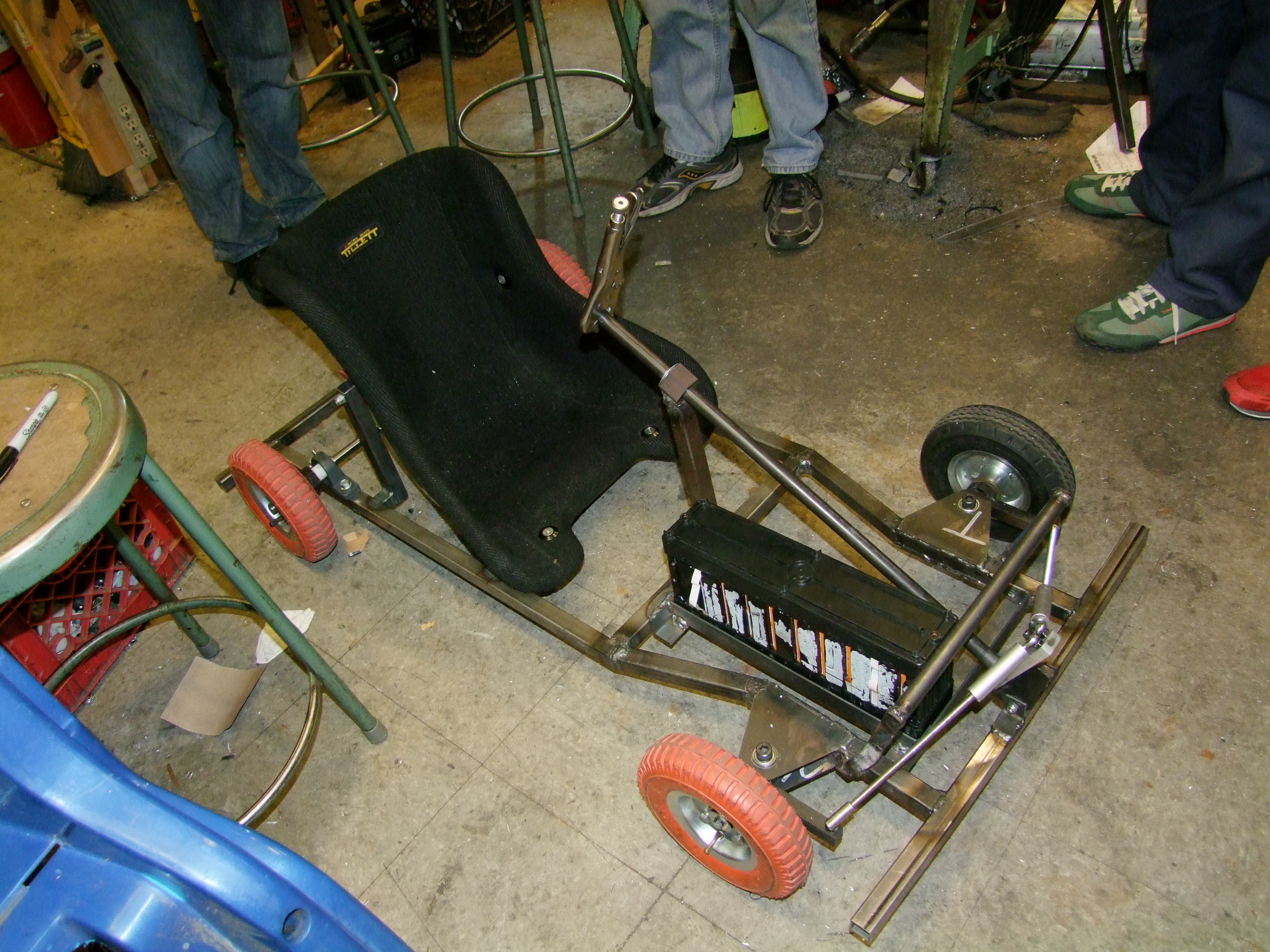
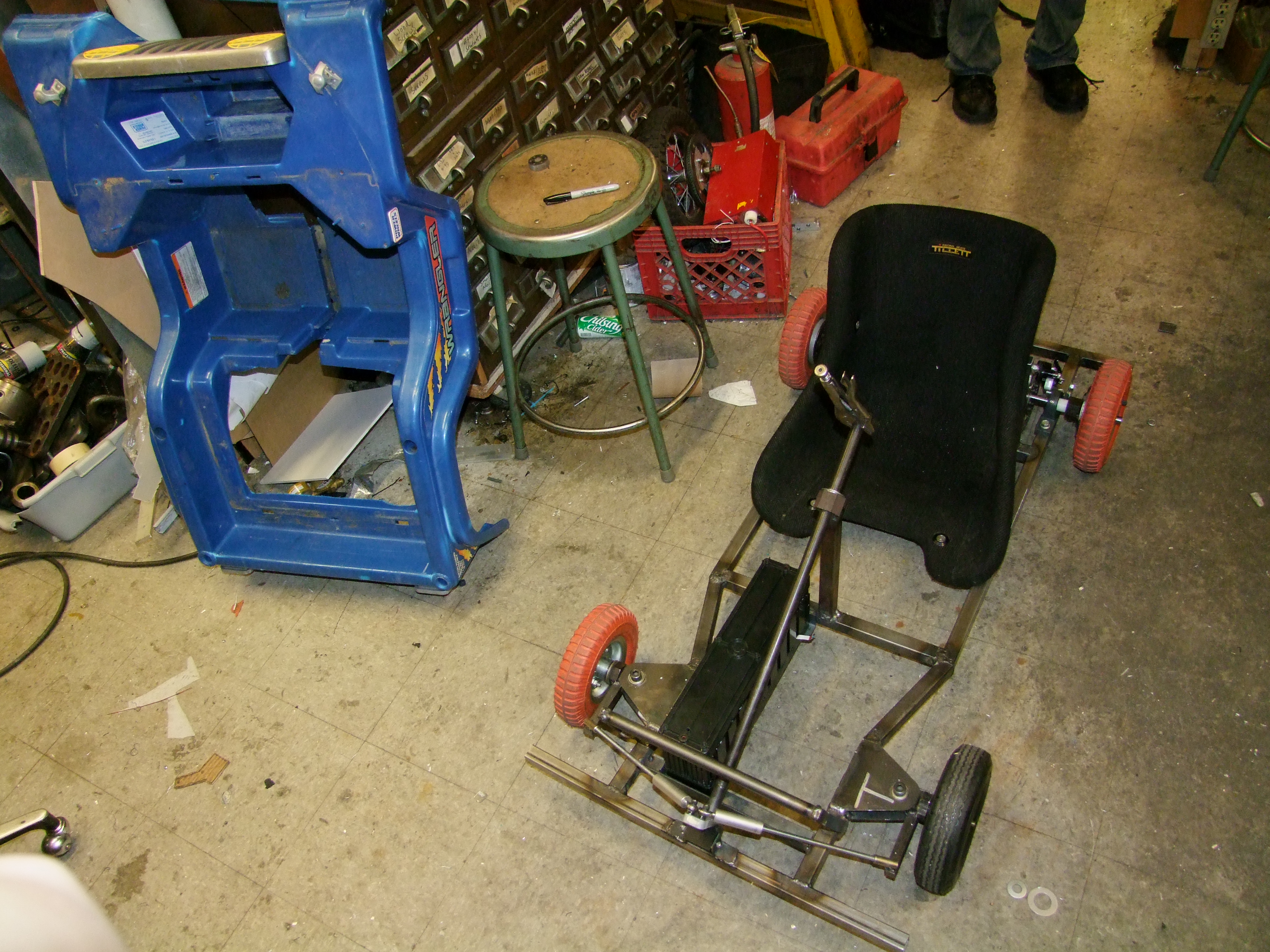
most excellent disc brake Ben fabricated the most excellent of disc brake mounts, which fit snug-ly on the newly key'd shaft. We eventiually opted to 'flip' the pillow block bearing mount to allow for increased ground clearance. More on the wheels and brake mount below. |
 |
 |
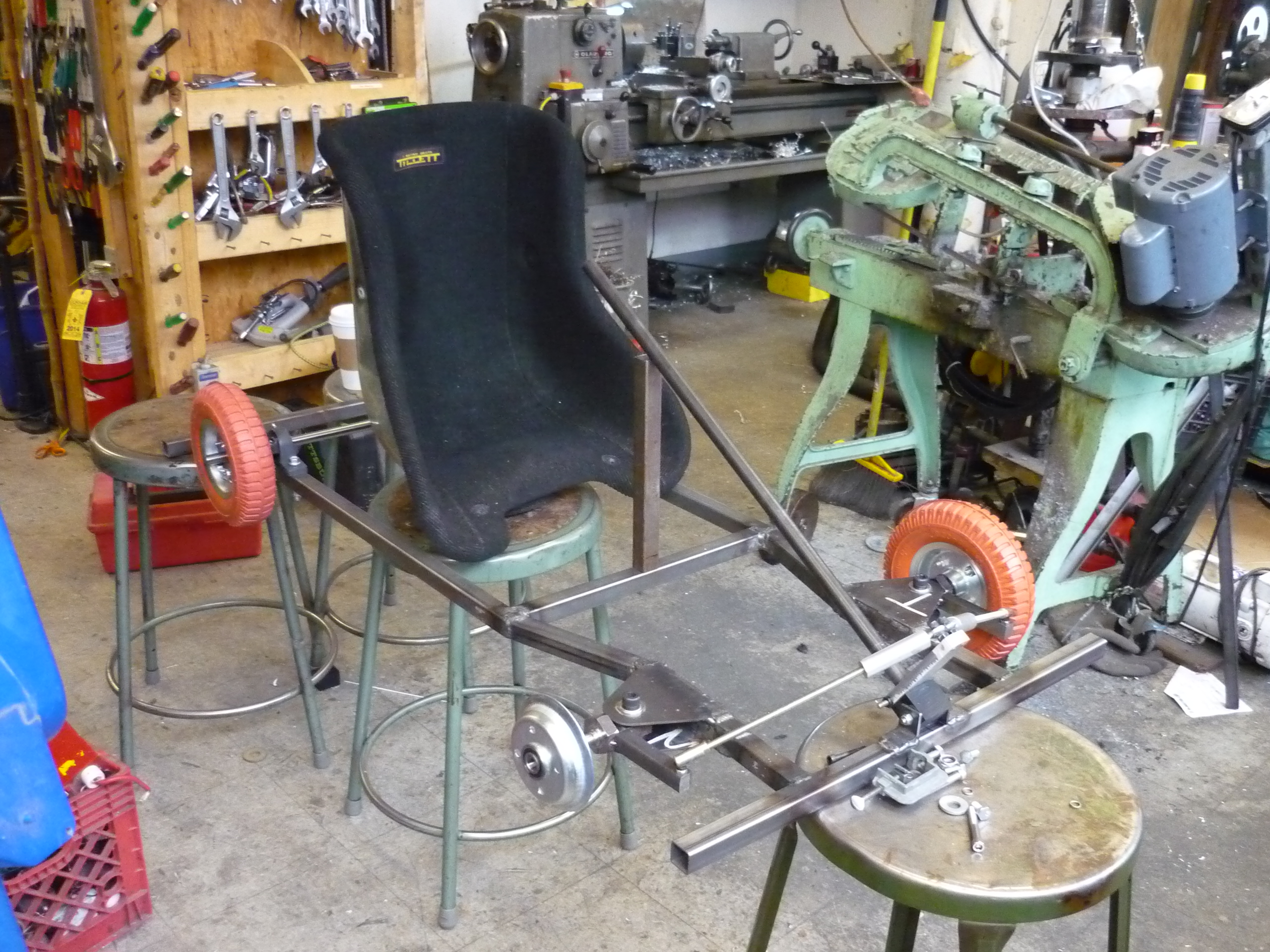
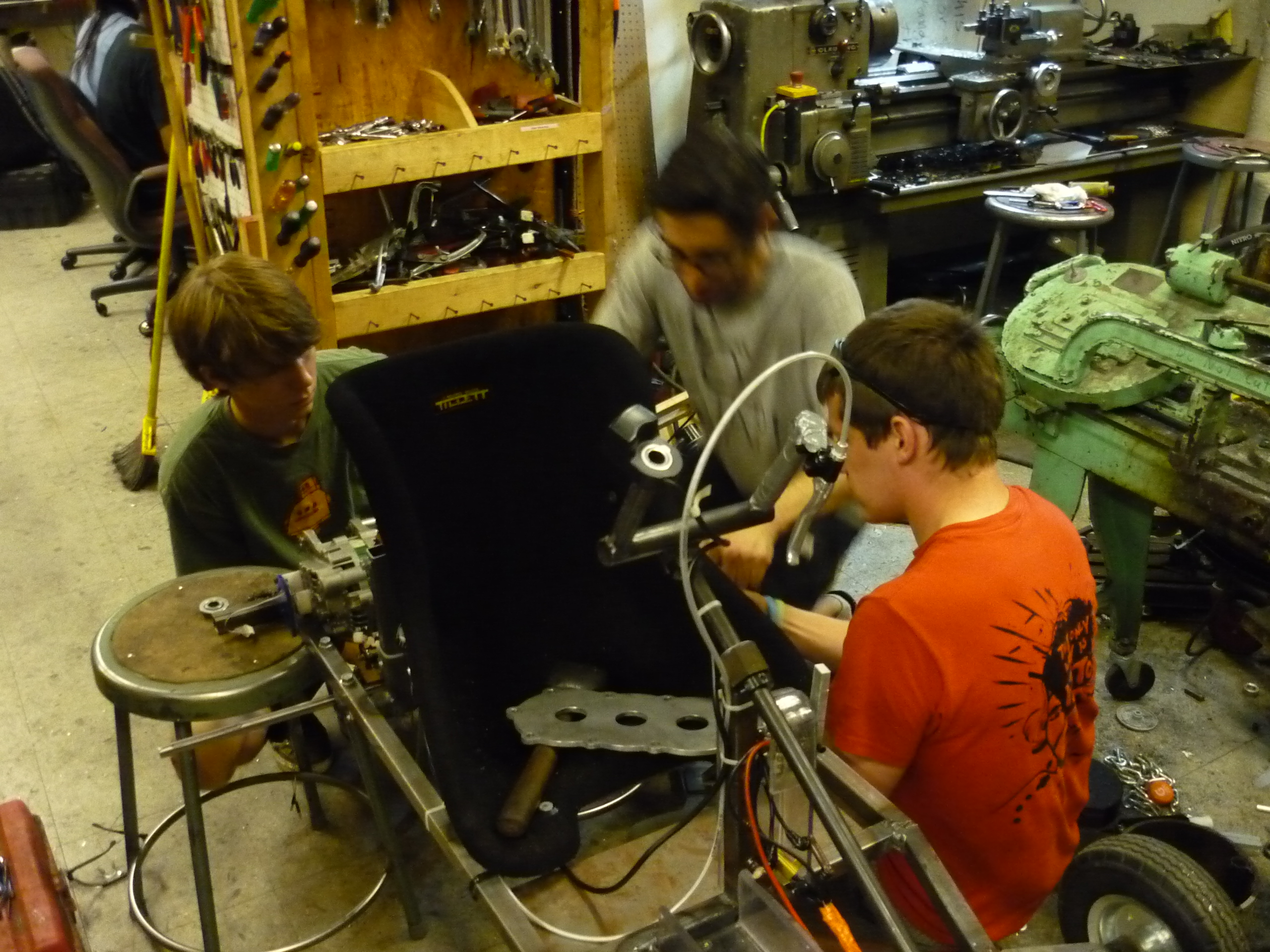
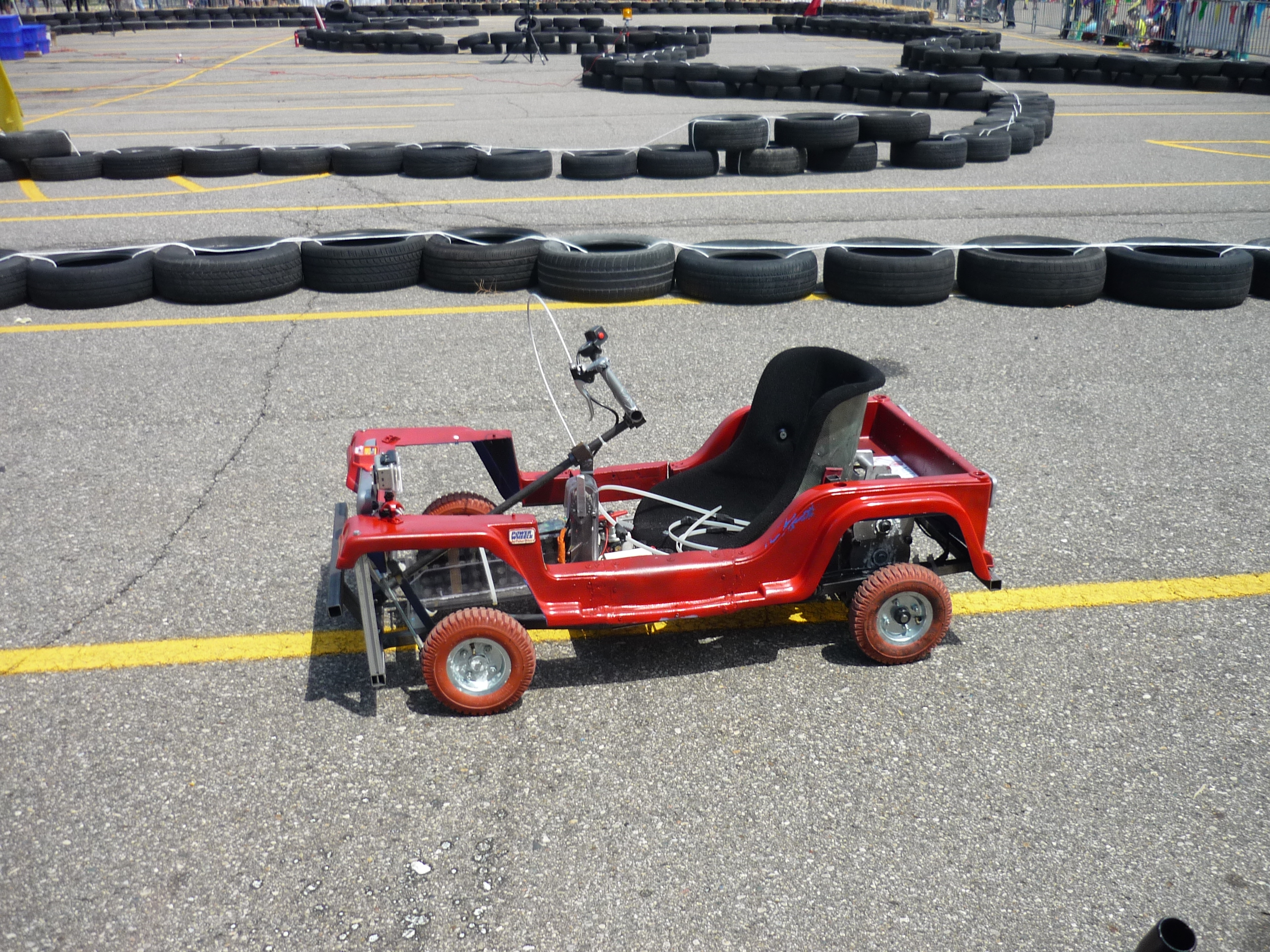
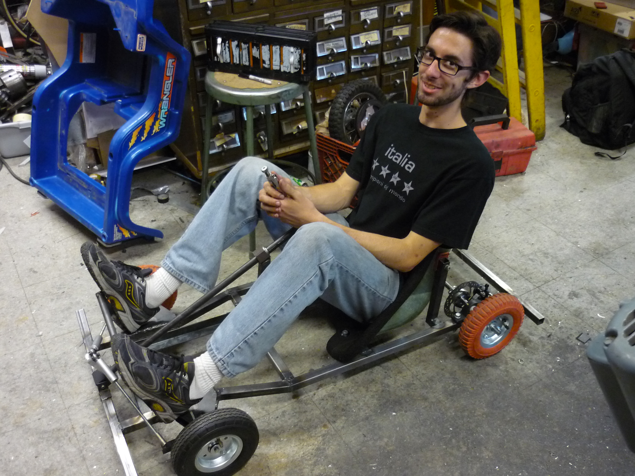
| Seat
was added, steering was completed and welding was had by all and like that it was becoming a kart, bowden-brake cable in place, steering assmebly solid. The seat grew tack-welded braces. All we needed were some gears. |
 |
 |
| A
quick battery box was born Polycarb and a heatgun did wonders. It was snug enough for the initial 10S2P battery packs that it almost didnt require an external constraint. |
 |
 |


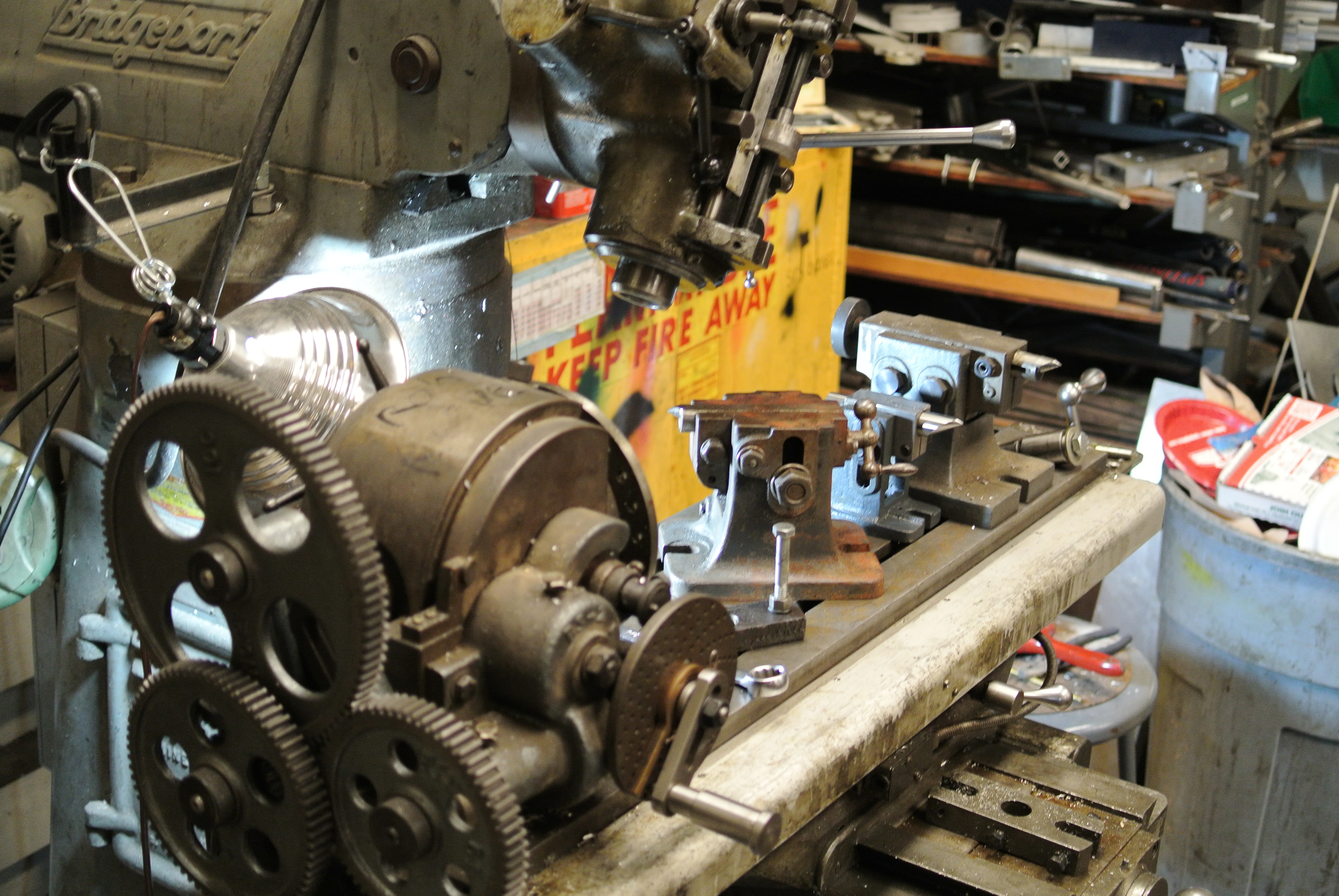


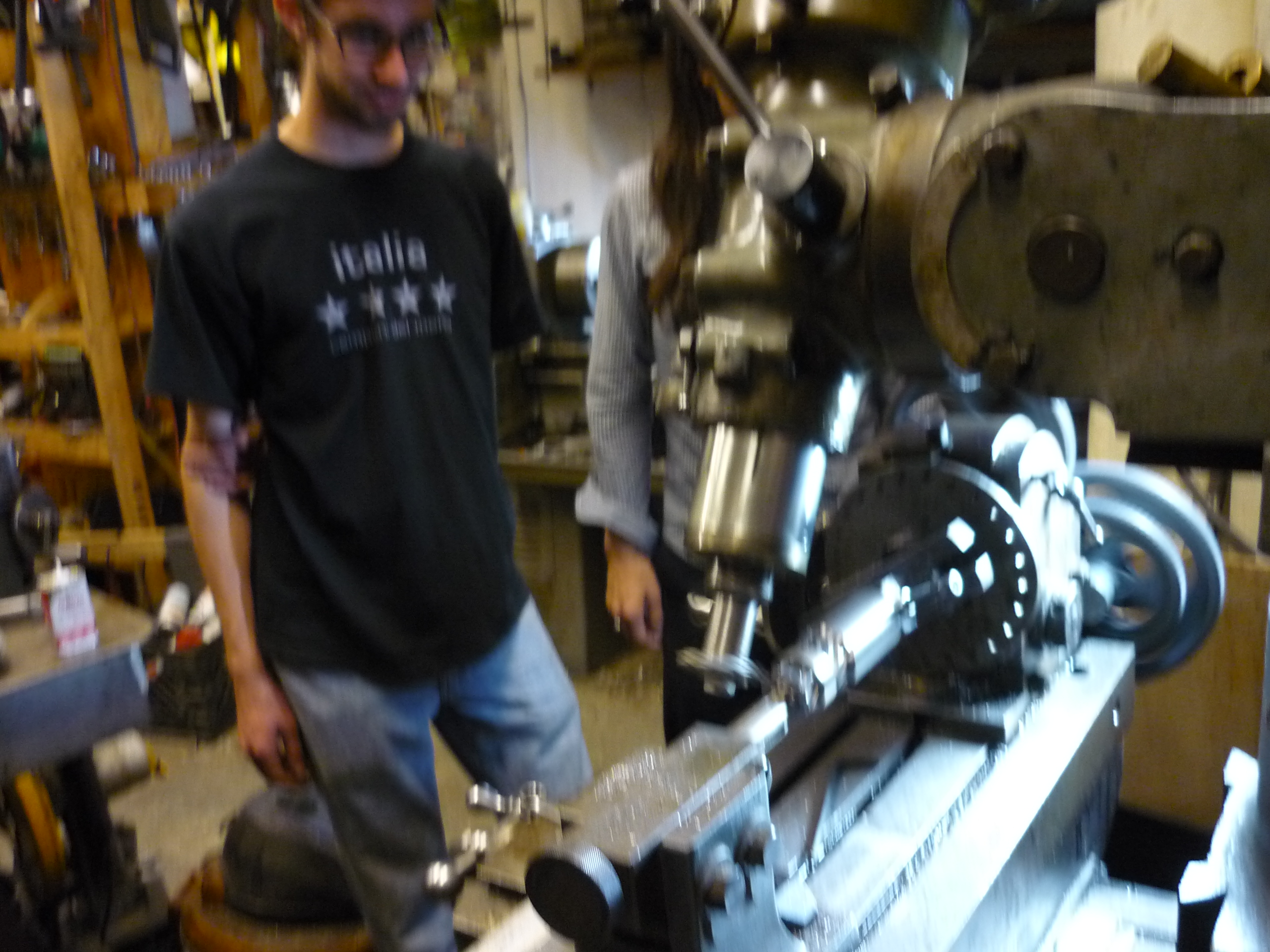

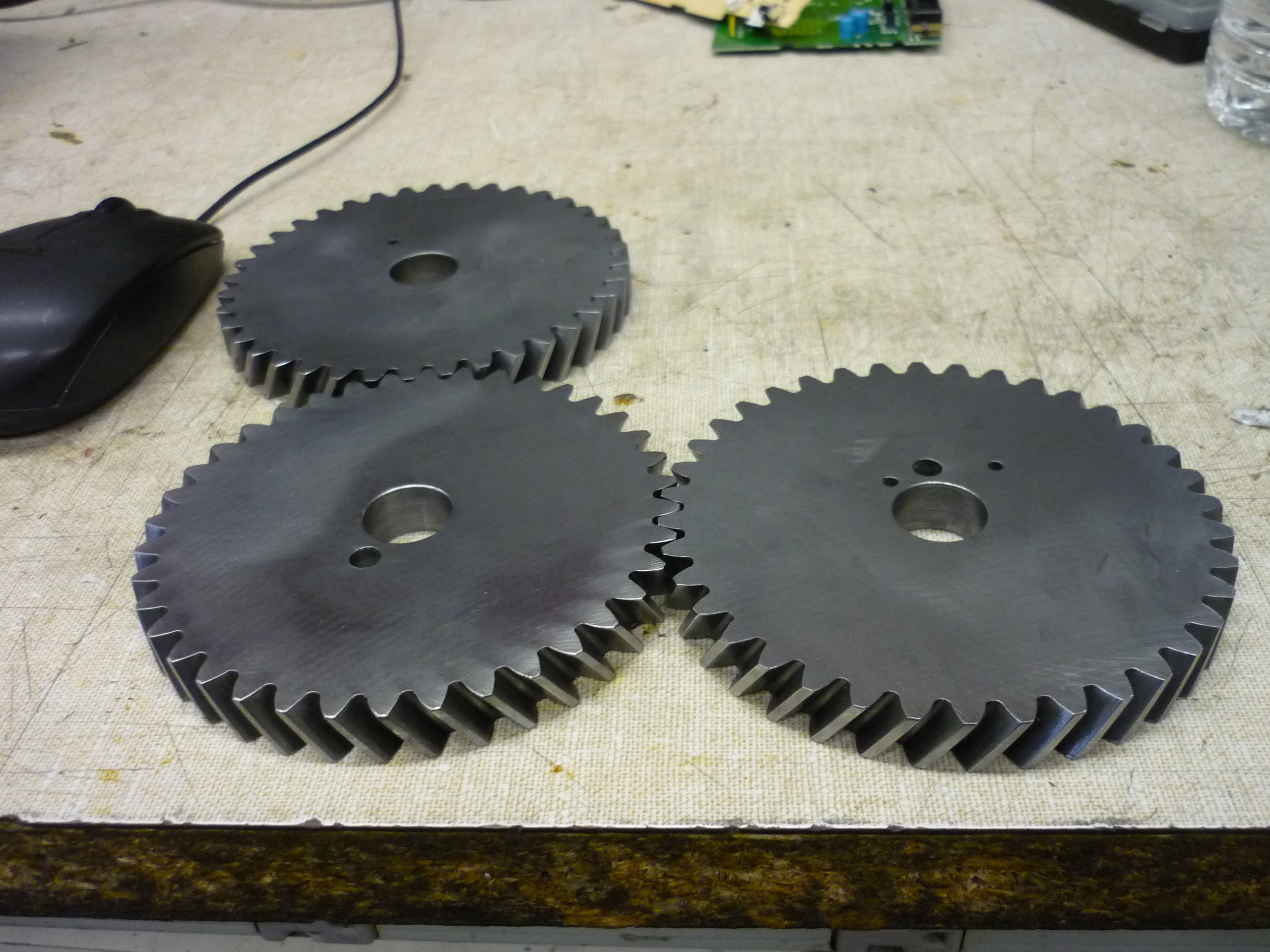
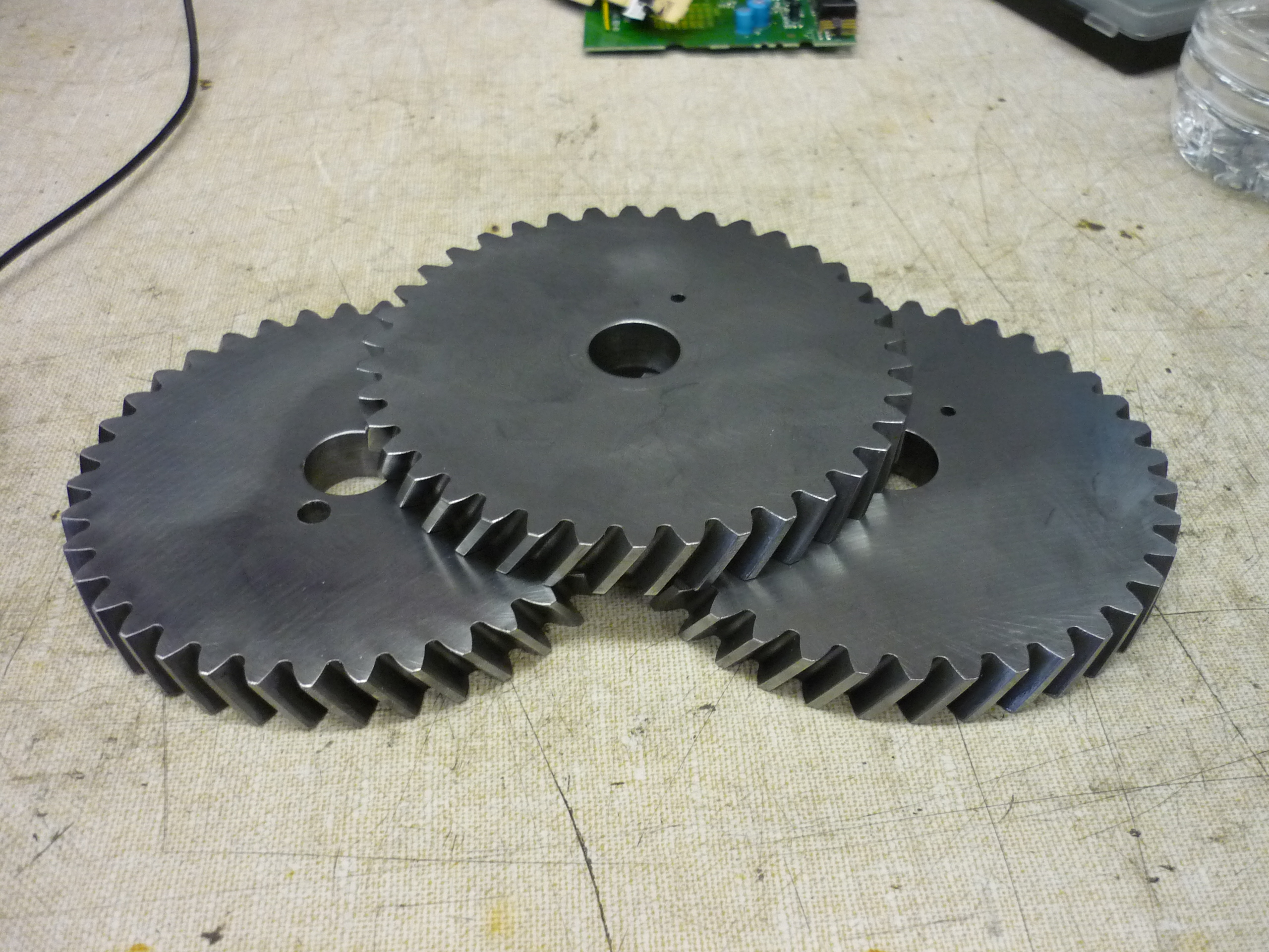
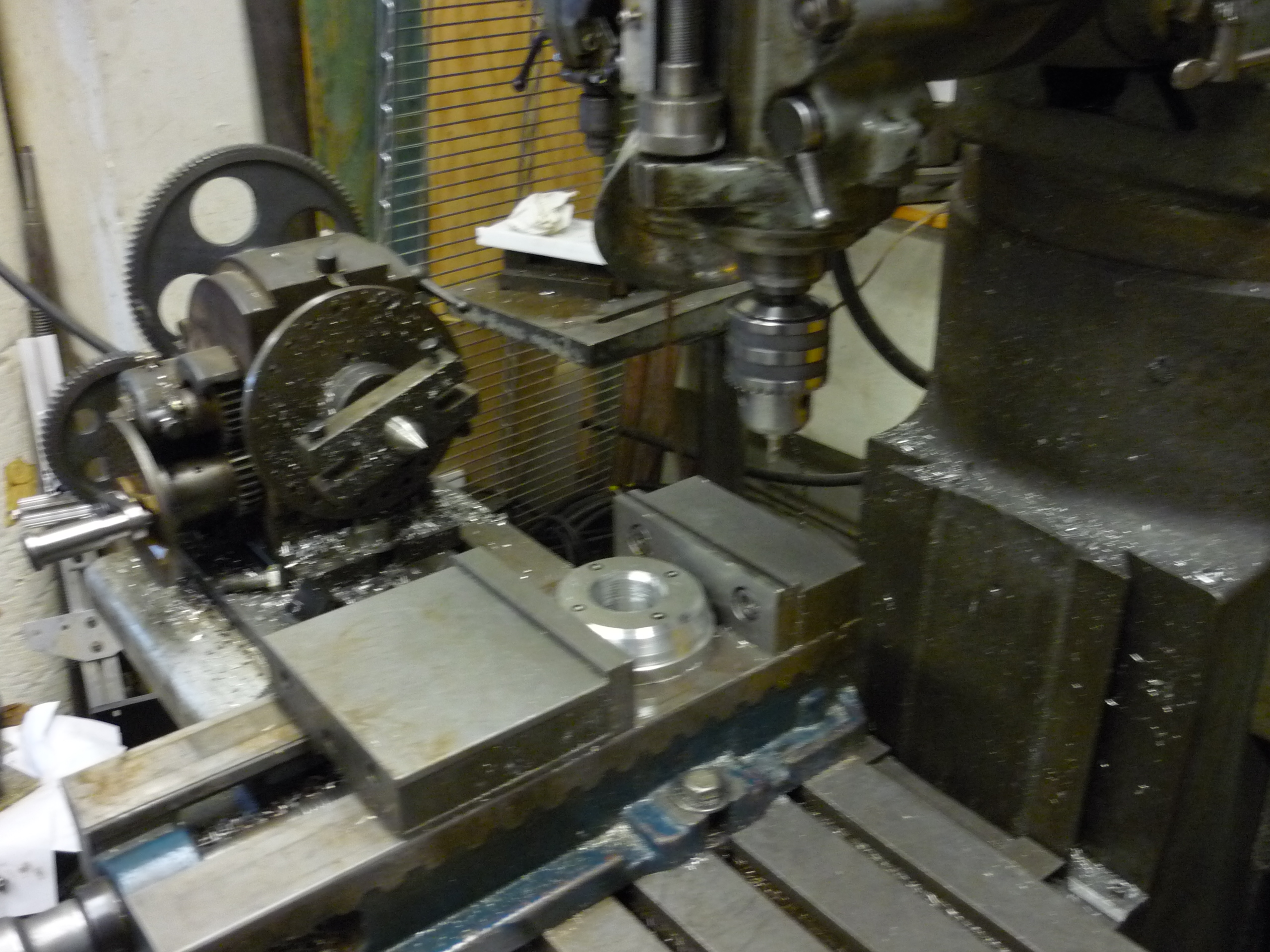
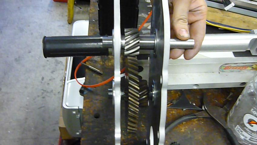
| Rob Reeve 'reeving' a gear | Image / Media |
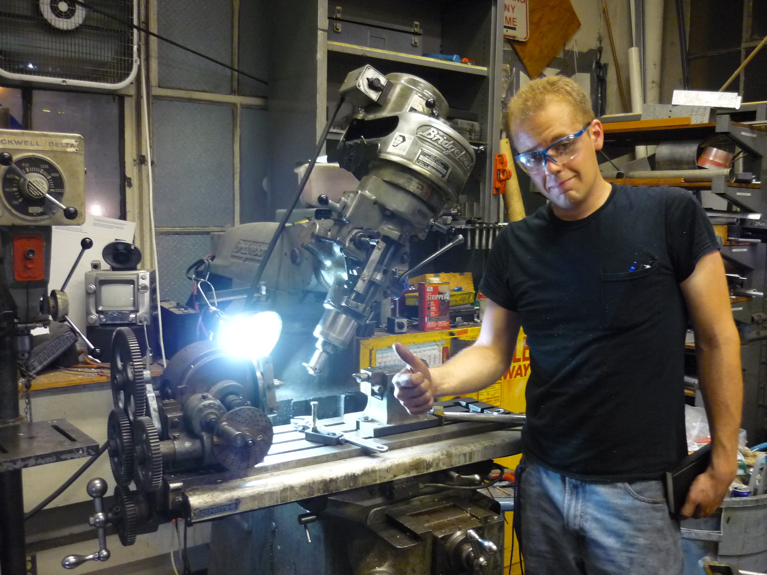
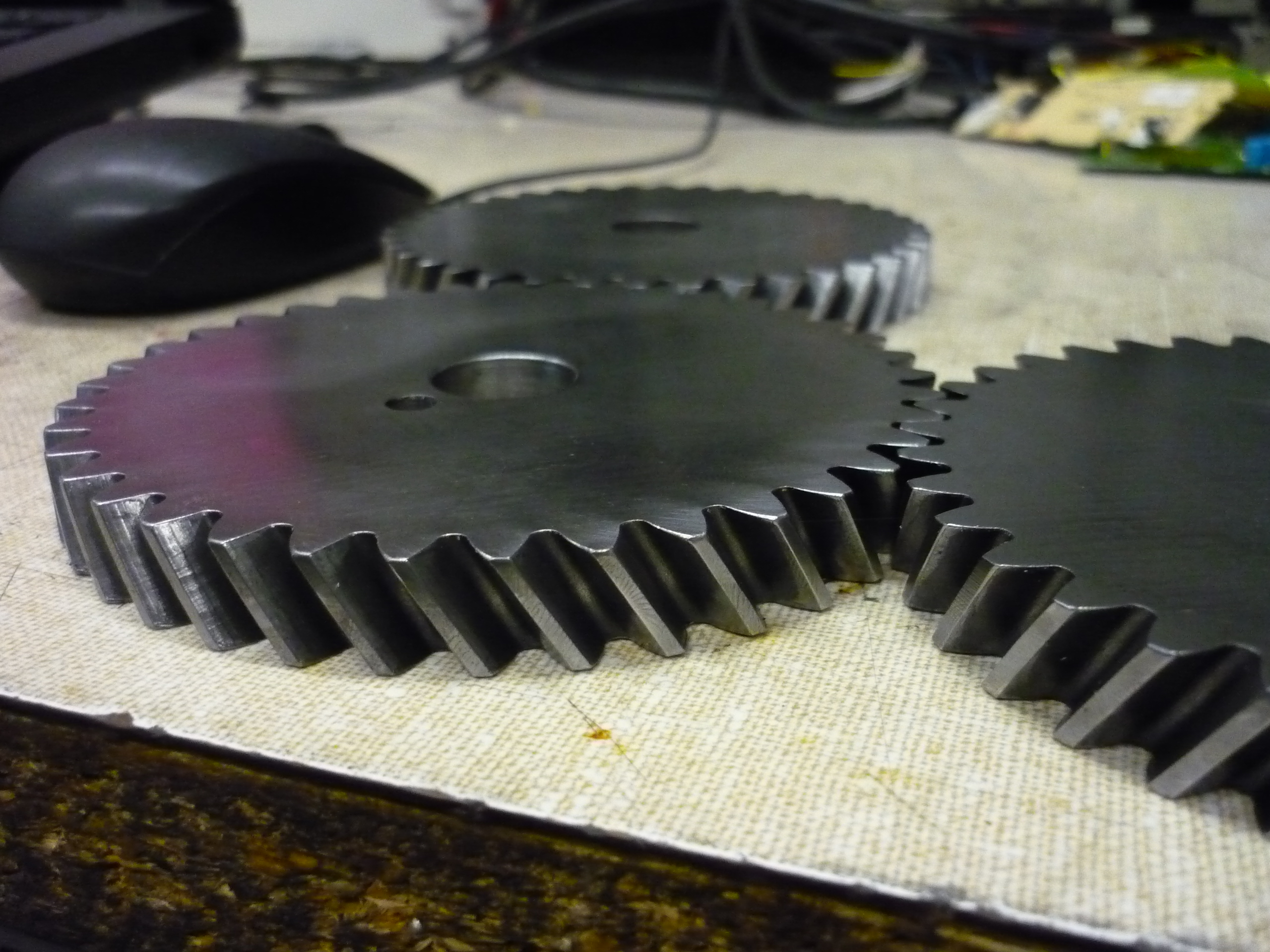
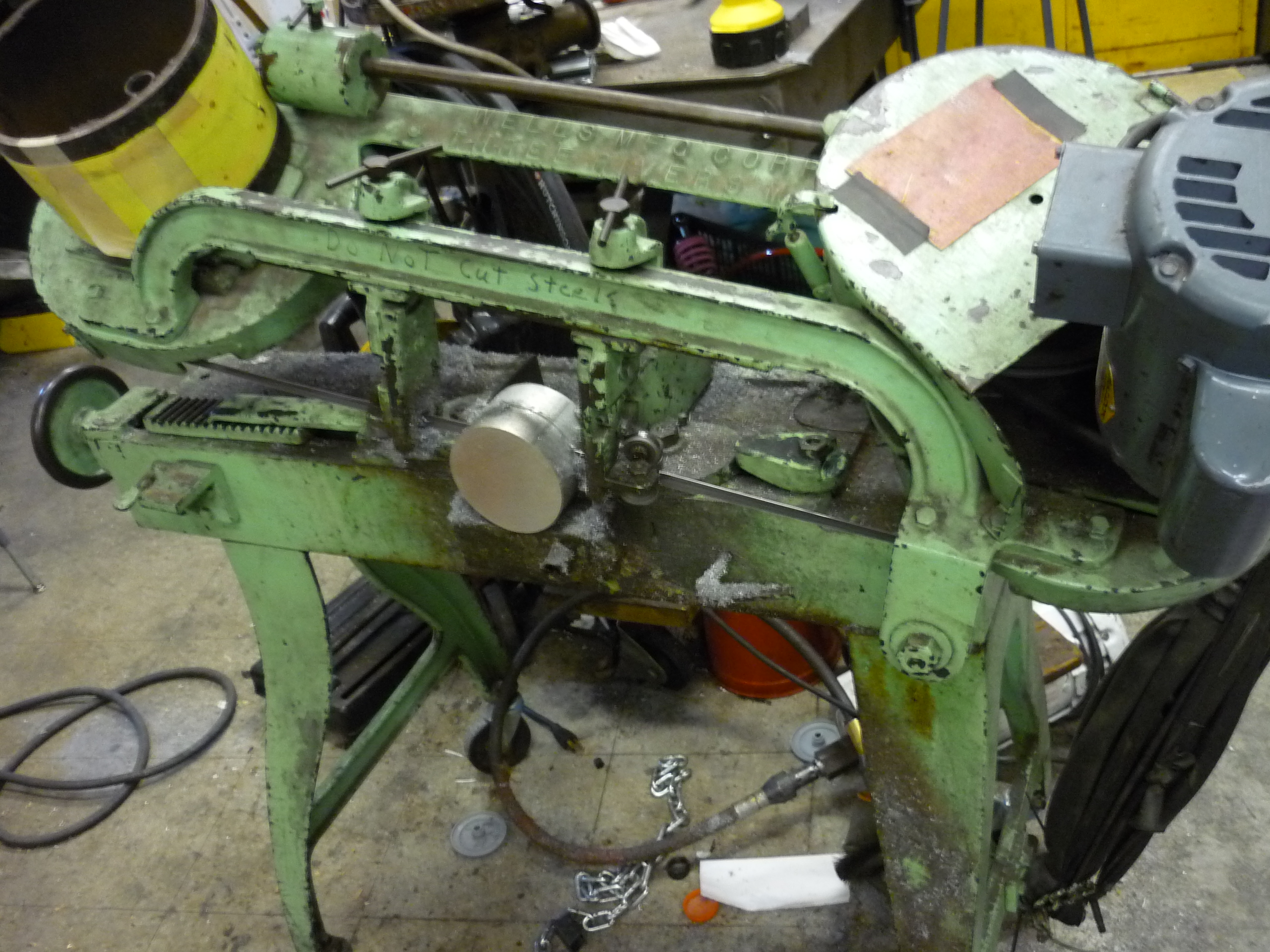
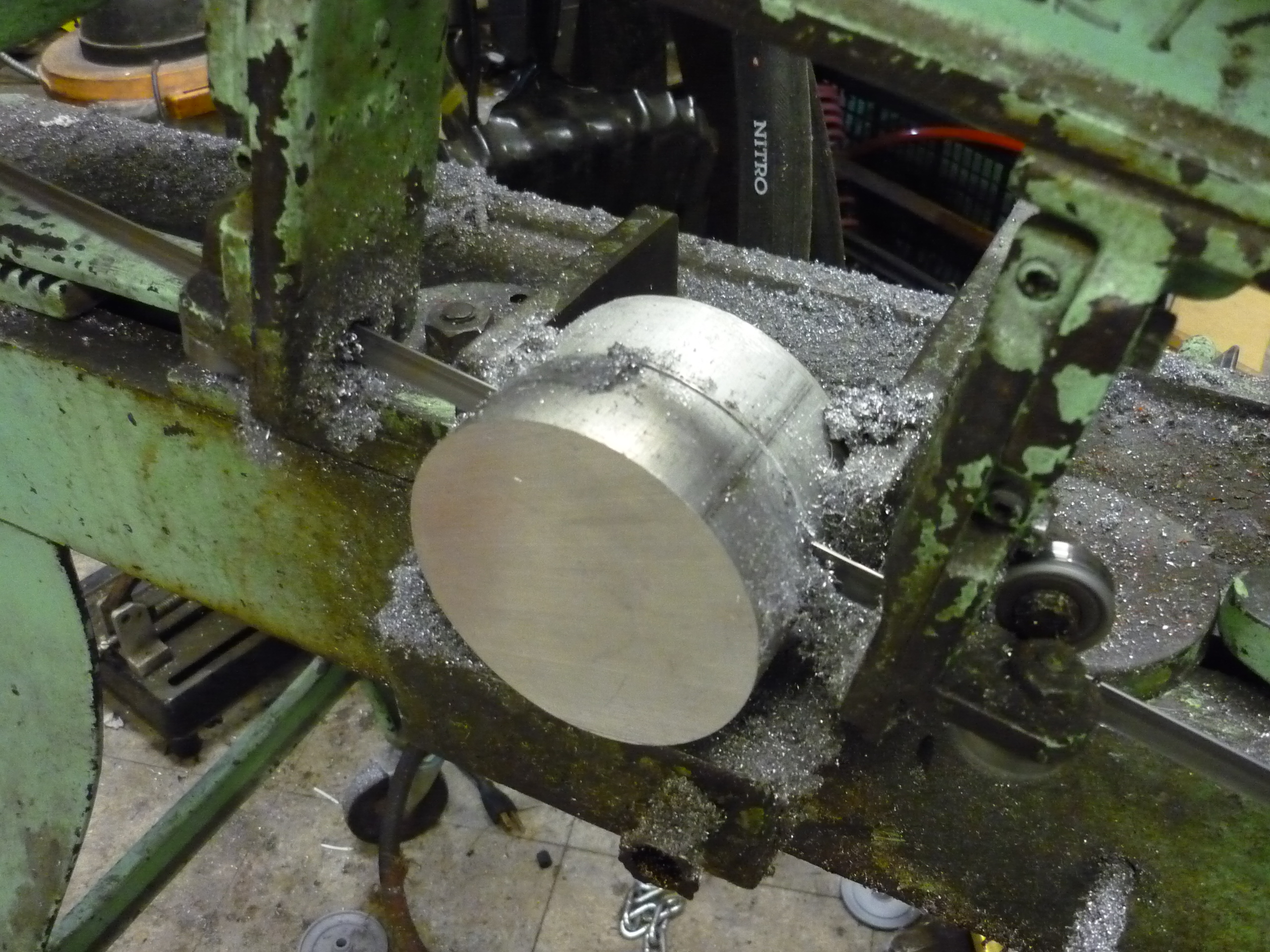
| The
following is three seperate shots of the making of one of the smaller
helical gears. It was a sight to behold, full of manual cranking with a
huge wrench. |
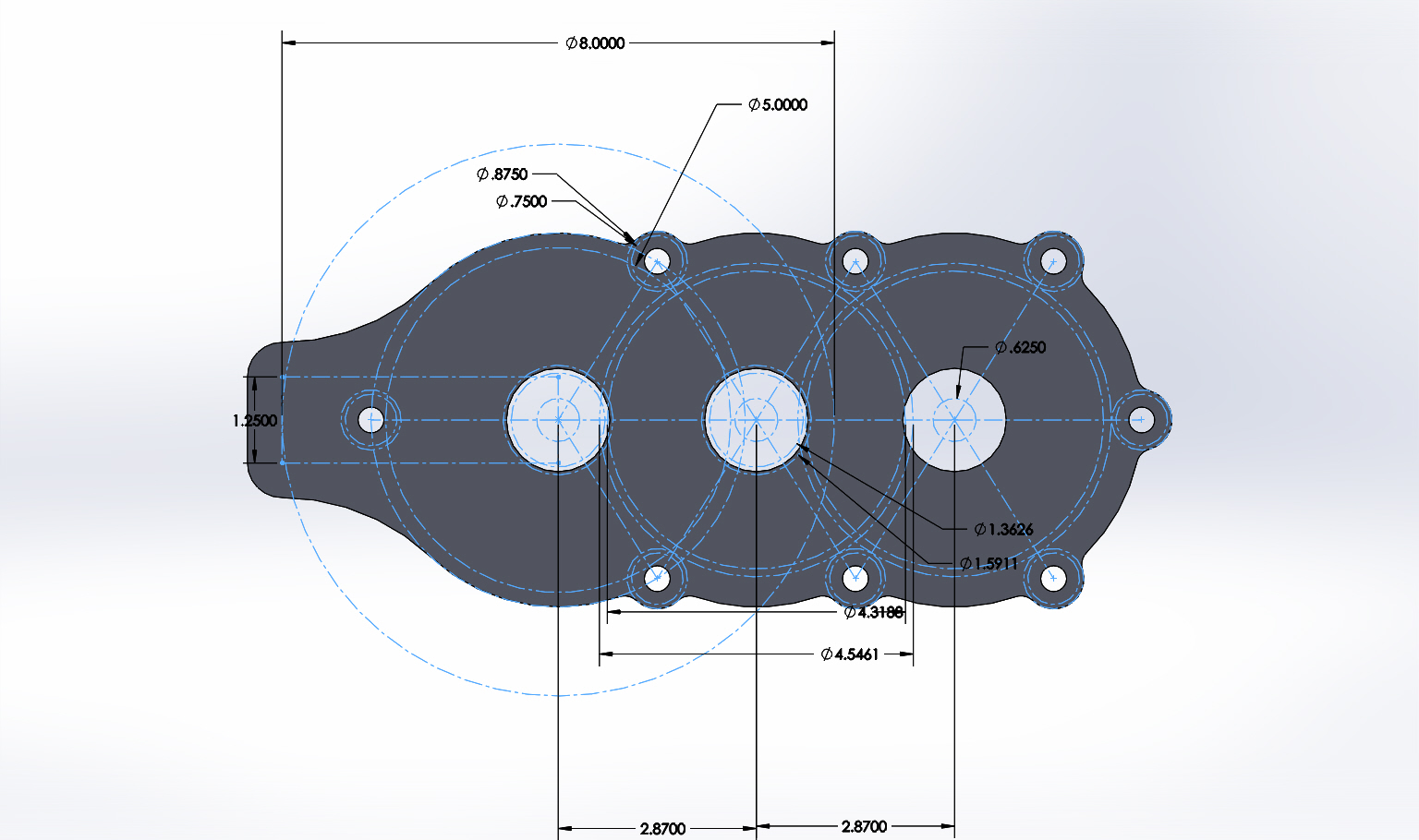
| Gearbox | ||
| After the gears are complete, they are haistly welded to 5/8 shaft, and mated to an extremely sexy, haistly waterjet housing. Ben worked his magic, which is why the thing came out frigging gorgeous. Unfortunatley there werent many pictures of the fabrication as it happened day-before heading to detroit. | 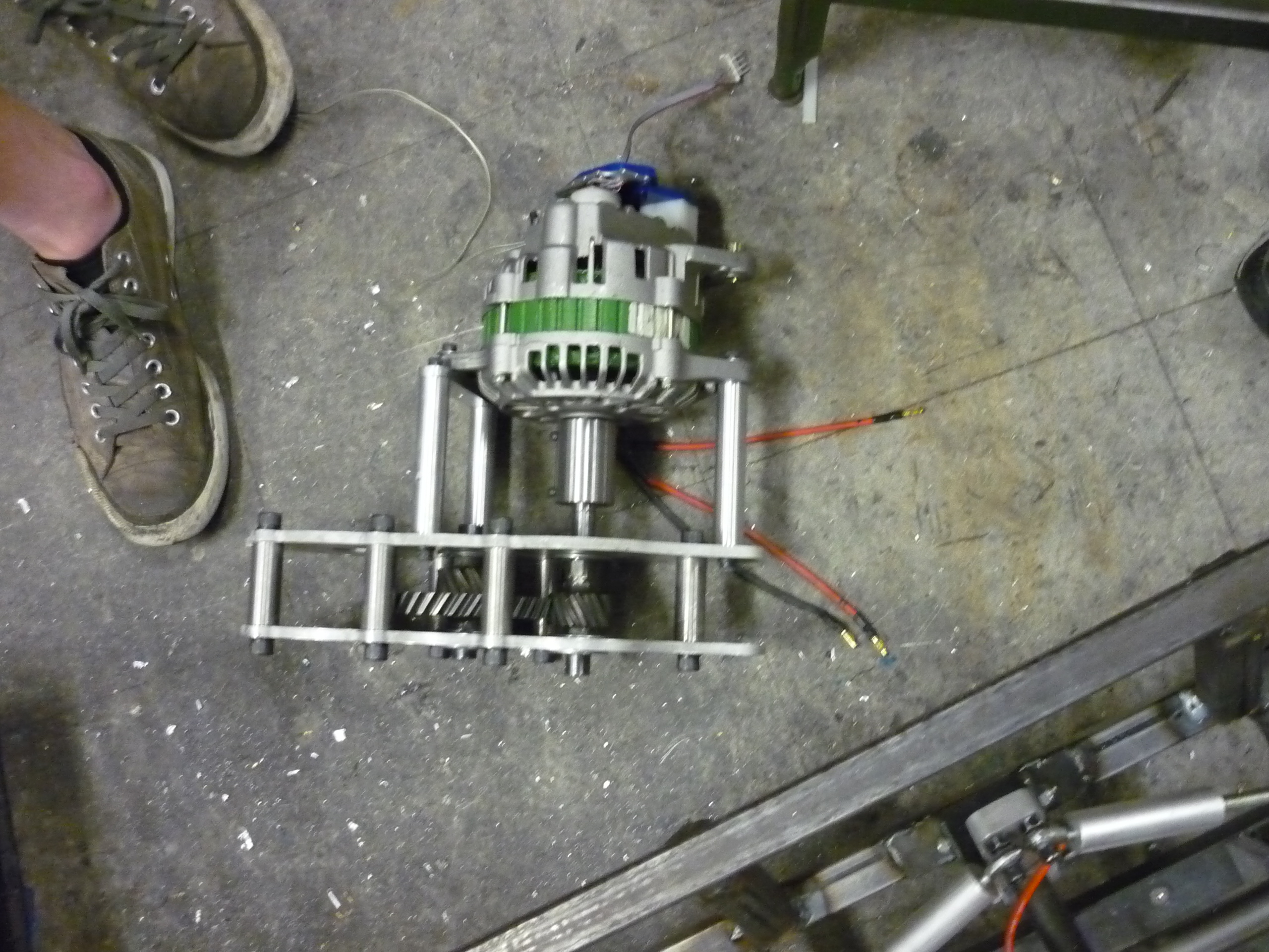 |
 |
| The side plates of the gearbox were haistly waterjet from 1/4" thick 6061 aluminum plate. Spacing for the actual gears was very critical, the holes are for the 1.25" OD , 5/8" ID ball bearings. The bearings we used, link, were actually fairly horrible, get proper abec bearings people | 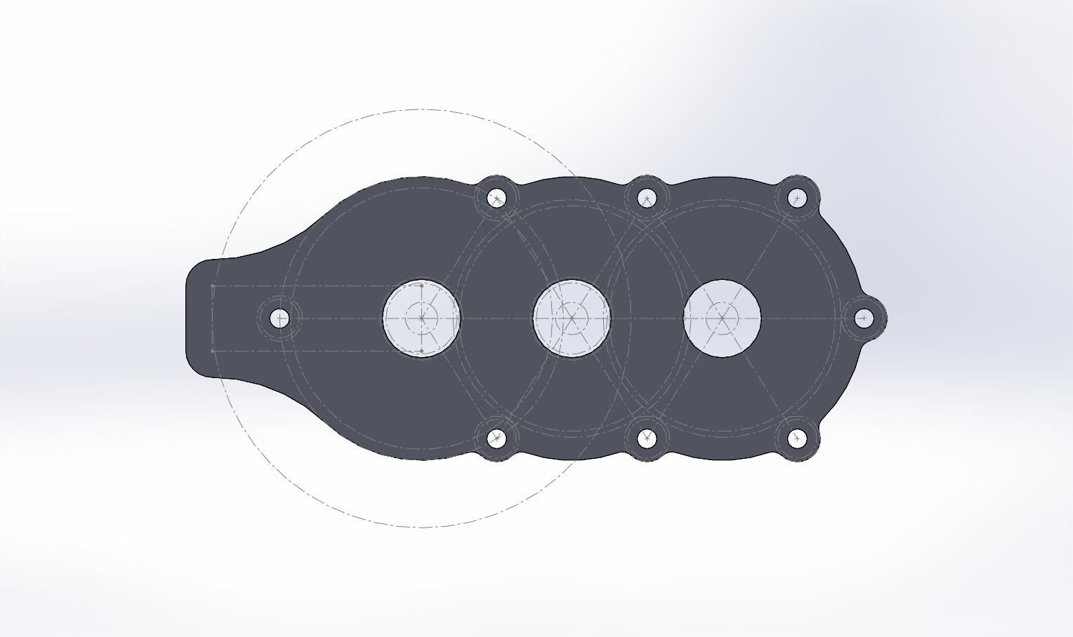 |
 |


| Moving on from alternators | ||
| After
bench-testing everything related to the alternator-drive, we transfered
over to battery power. unfortunatley, the Dc/dc converter's caps
couldnt take the voltage transient. This was approaching the deadline
and the midnight hour, we
switched from sensored alternator to a backup-motor. We scrambled and
mounted on a brushless 3phase 180kv/rpm motor. This is the same motor used in the submersible thruster project |
 |
 |
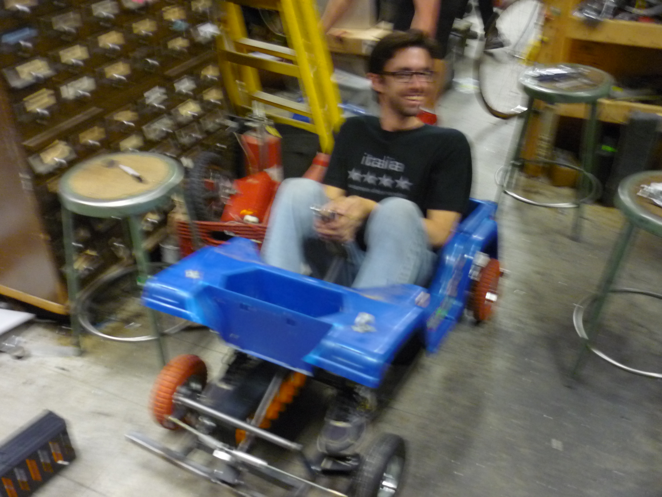
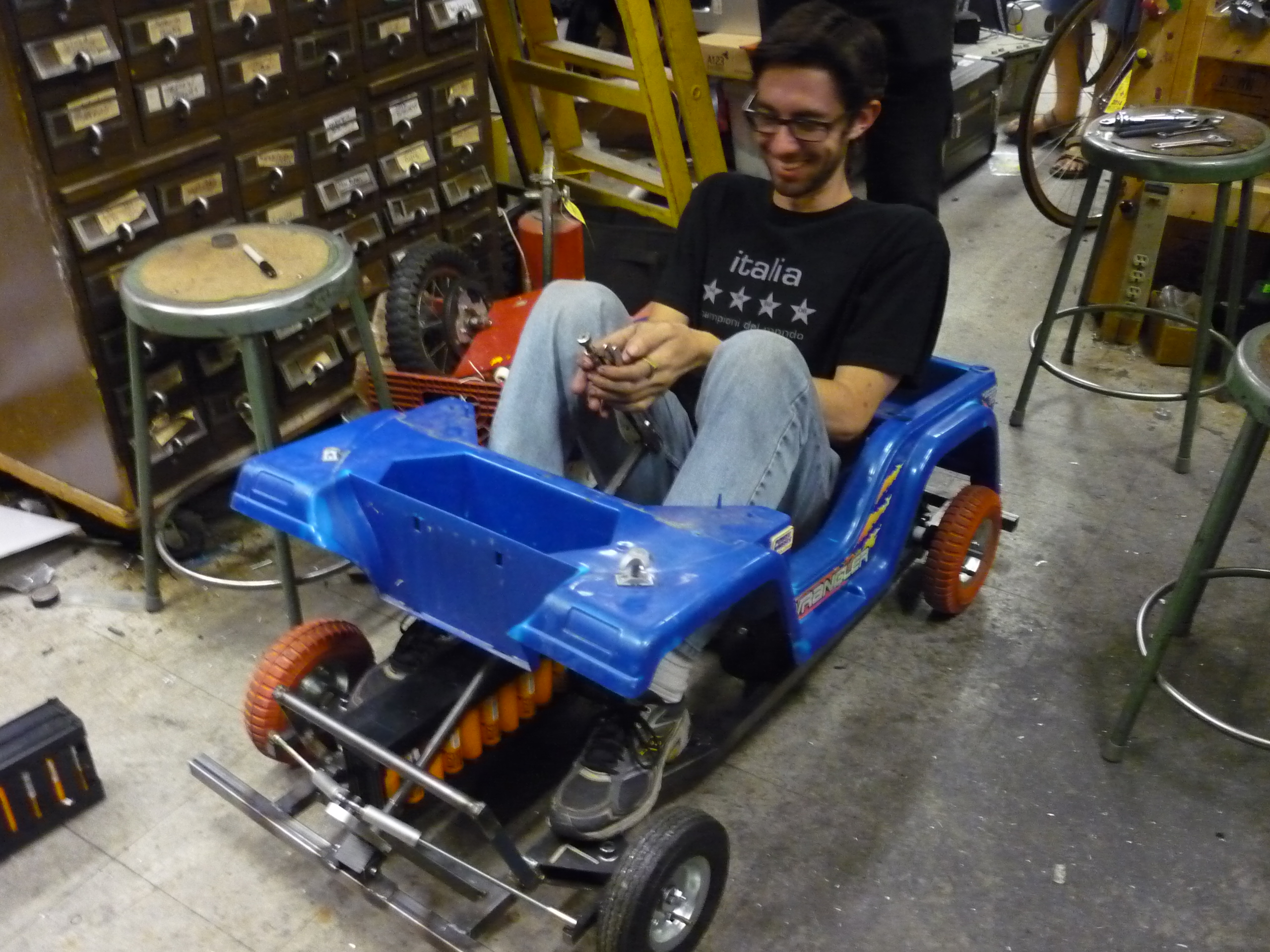
| Retrofitting,
tweaking and the sunrise happend. THE FIRST TEST, morning of the trip to Detroit. |
|
 |
| The First-ish launch | Image / Media |
| Morning
of the trip to detroit we fired up the correct gearing and the backup
motor, on a 10S (30v) battery pack. This and two other runs were the
only pre-race vehicle testing that were completed. SHIP IT! |
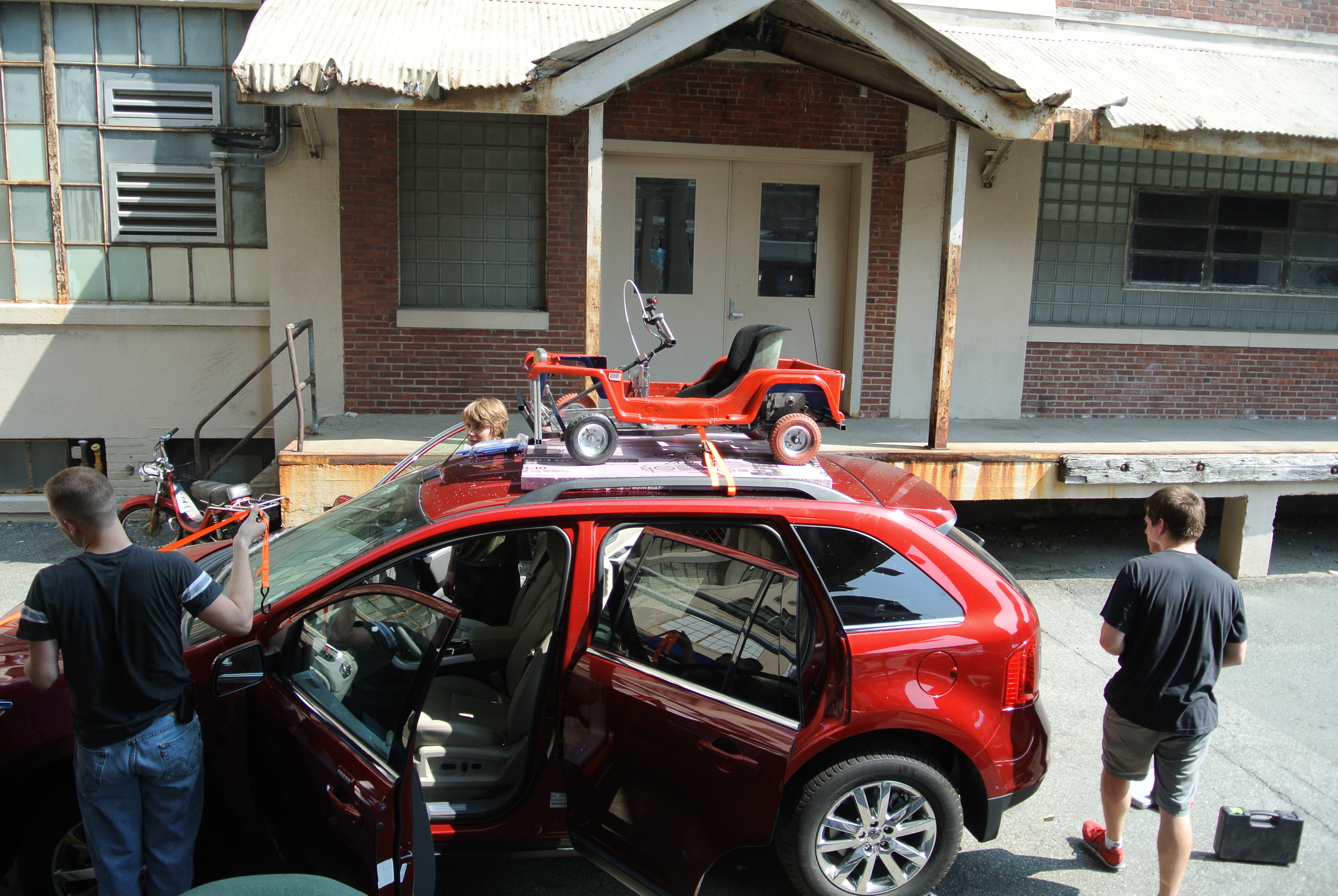
| Transporting and Racing | ||
| Using an MIT discount, we rented a 5 seater and gently strapped the atomic chibi jeep to the roof atop some happy pink foam. The shell was removed for transport as it was feared to fly off sporadically. We piled in a bunch of other gear, a mig welder, backpacks power supplies, spare batteries, chargers, laptops and a pile of extra harbor freight pink tires. We departed at 10:30AM, took a run to a harbor freight, acquired extra batteries and pushed westward. | 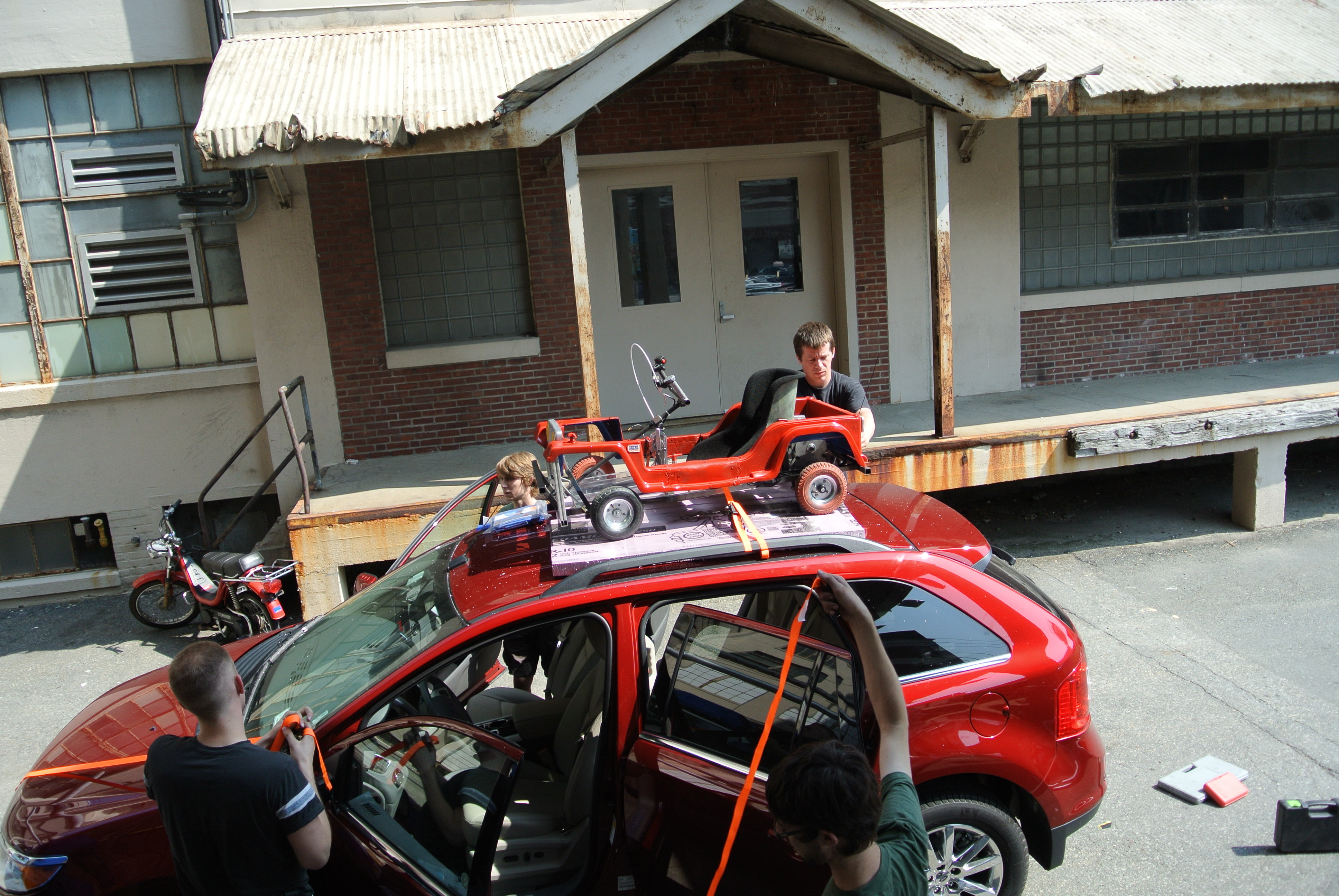 |
 |
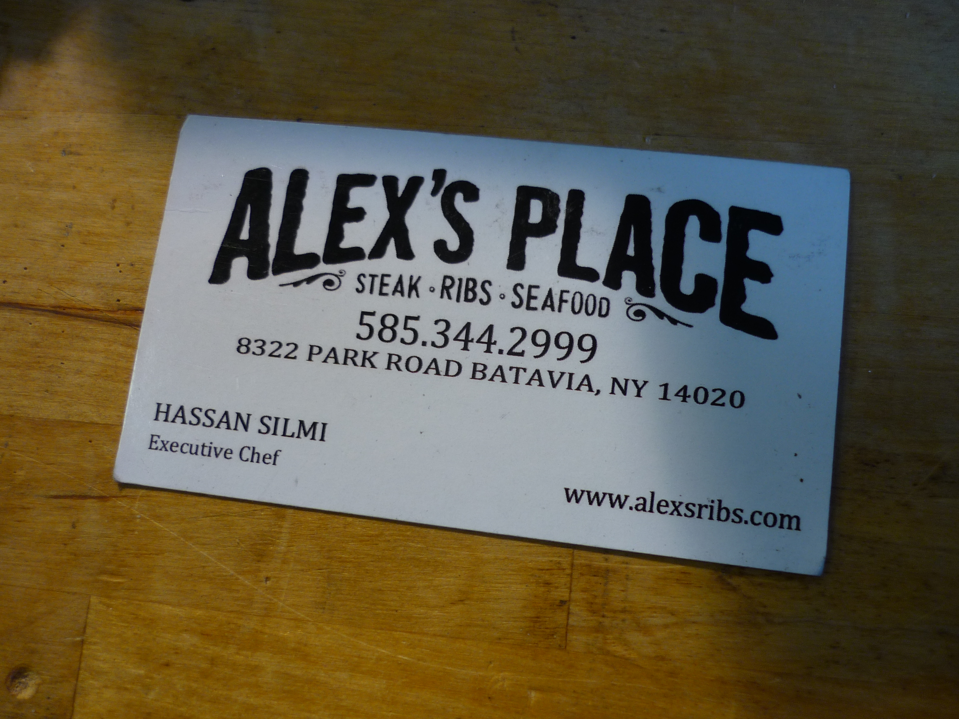
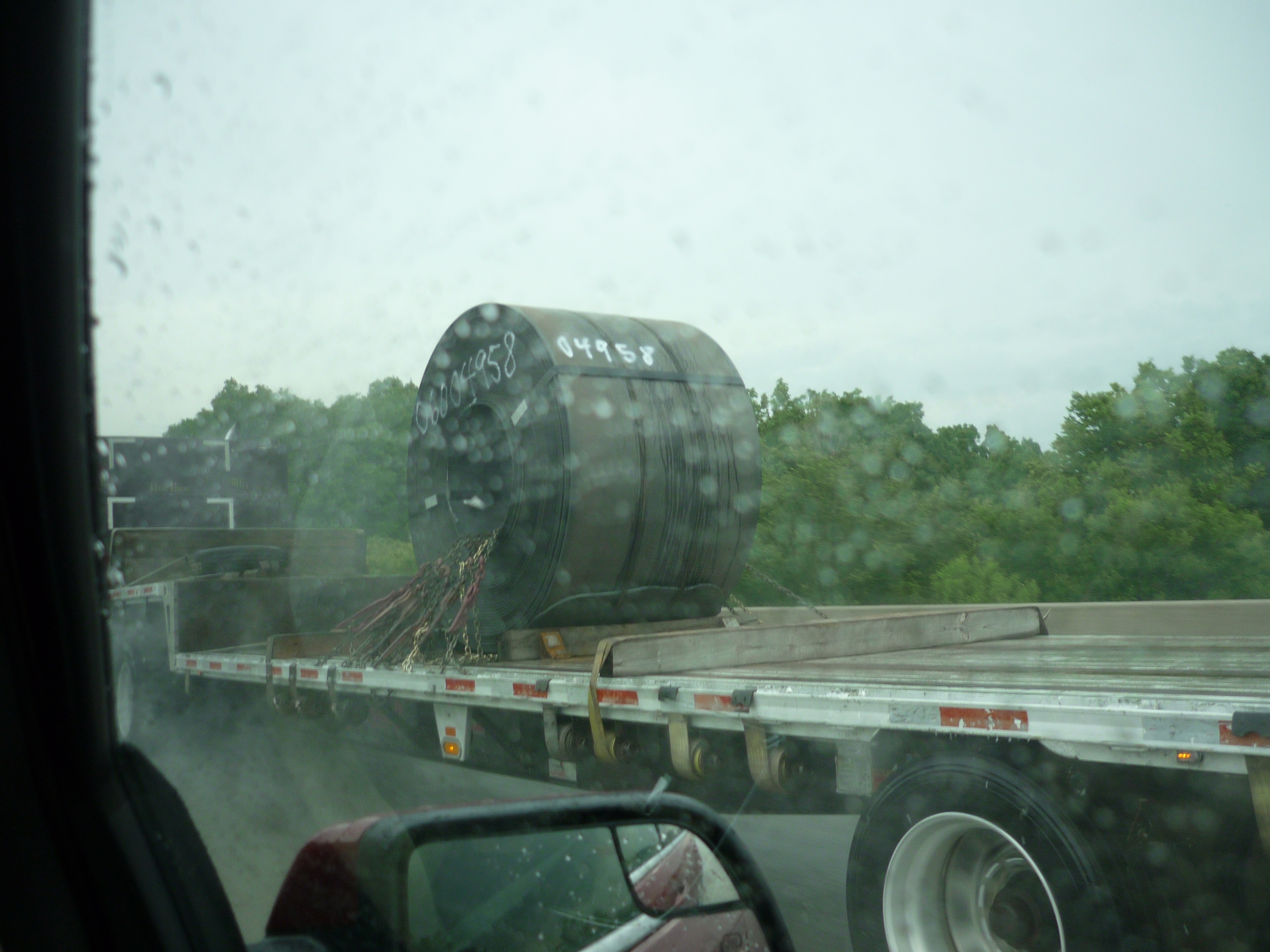
| Wubbed
Beef Around 8 hours later, 'wait people need food right' happened and we stopped off at Alex's place, somewhere near buffalo ny. We were tired from driving and integrated sleep loss from the previous week.For whatever reason the carniverous food there was delicious. We hypostulated why it was so good and determined it was because vacuum chambers. Hypostulating continued for an hour, as we were waiting for the check, only to find out it was there the whole time. Also there was some hot-rolled steel. |
 |
 |
| We
arrived in dearborn at~3 or 4 AM And promptly fell asleep. Time trials began 5 hours later, after some dazed and confused IHOP, somewhere near detroit, the troops were ready for action. Charles G and comrades had already mostly setup, and we joined them in a very cozy tent. |
 |
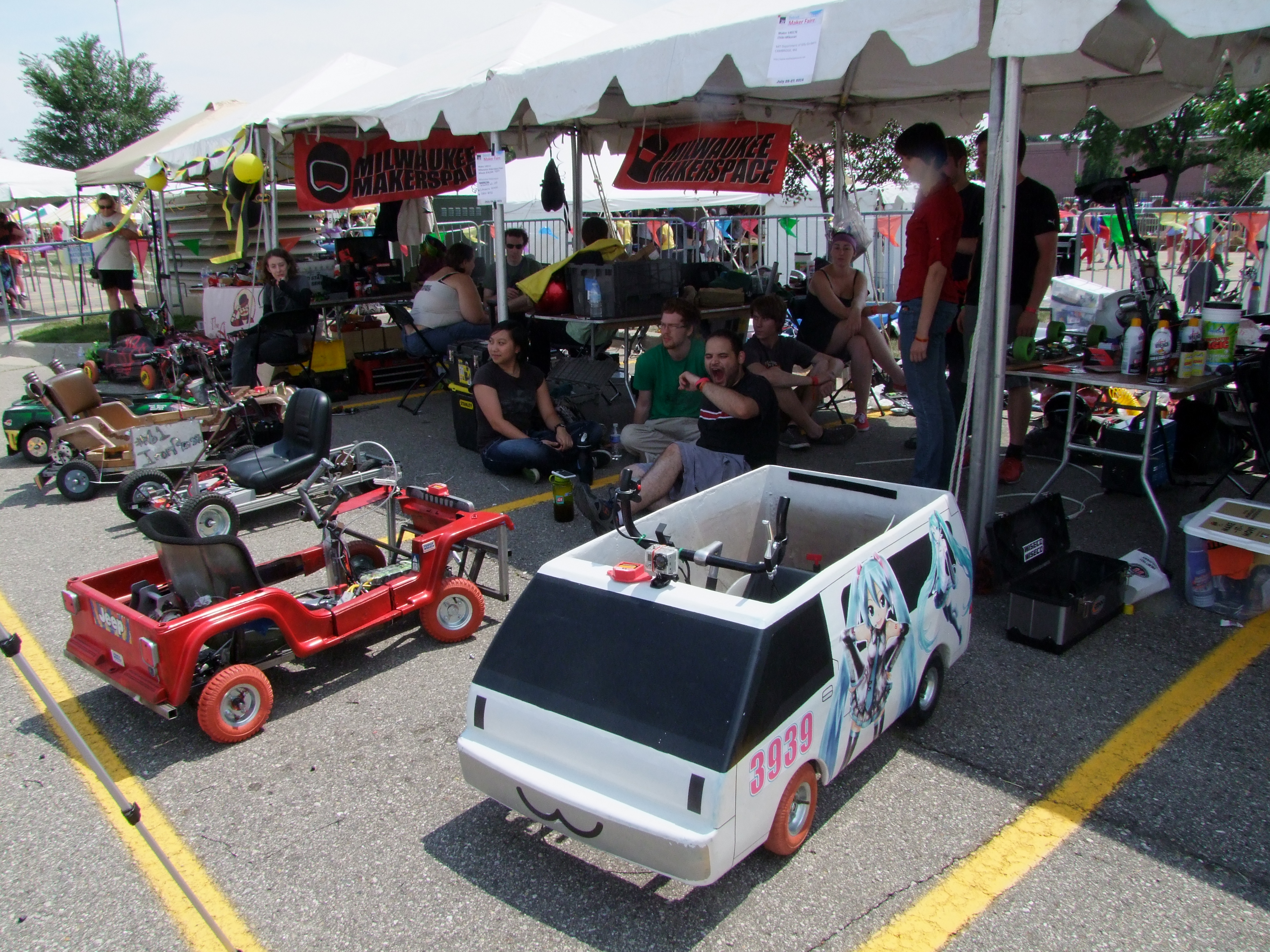 |
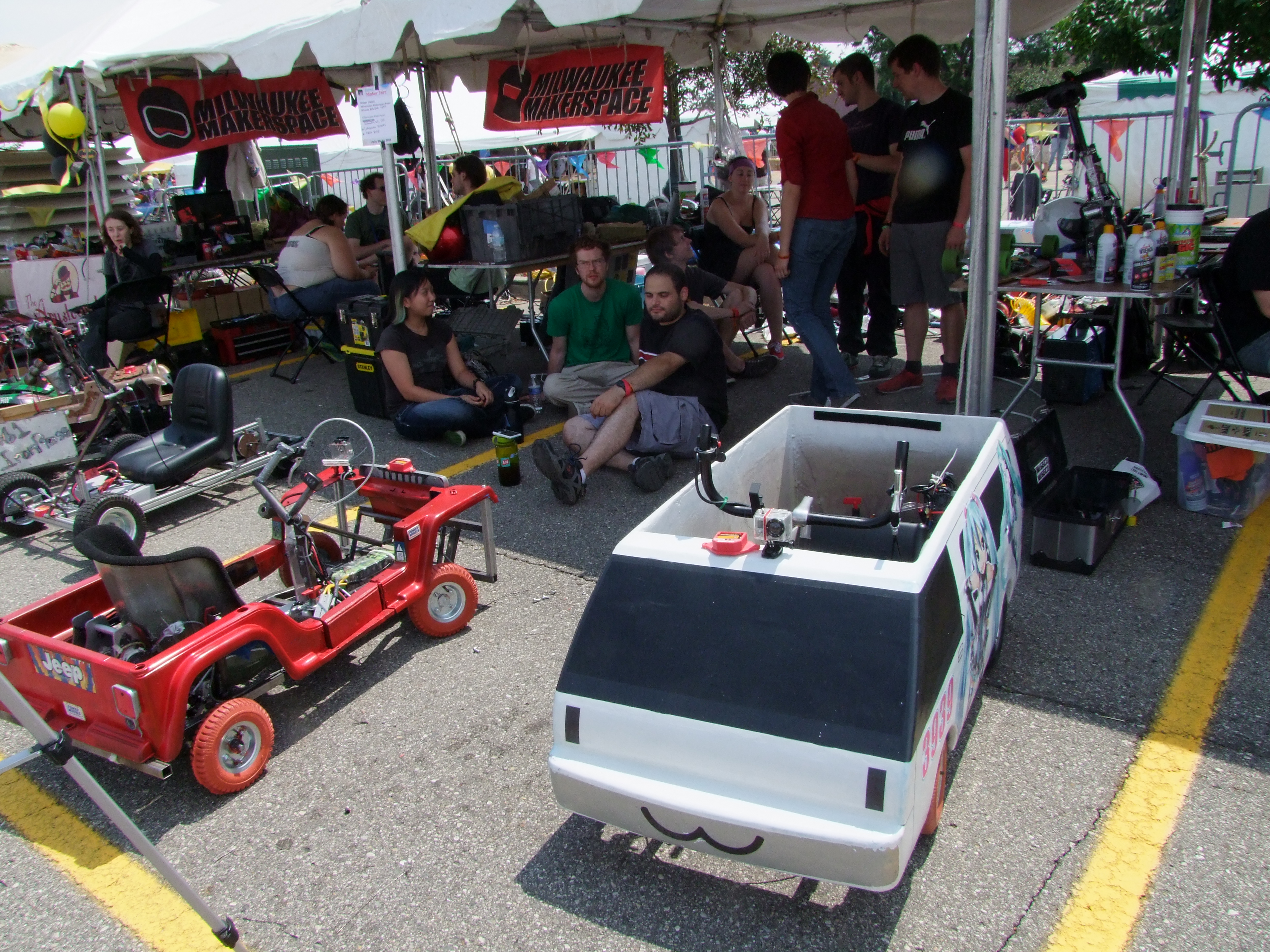
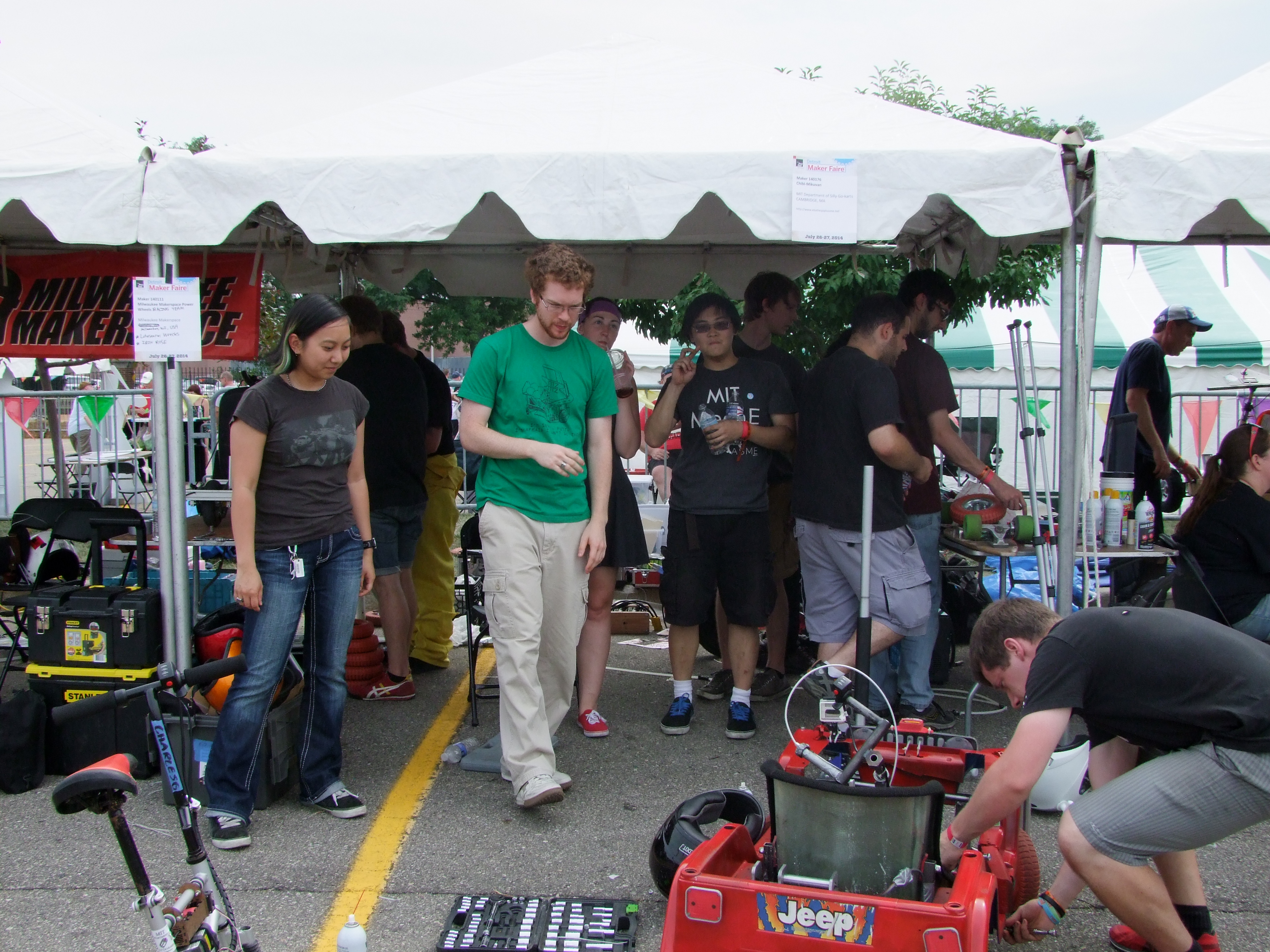
| Chaos
and planning the chibi atomic jeep side by side with the chibi mikuvan. Months of planning vs 3 hours of testing before racetime. |
|
 |
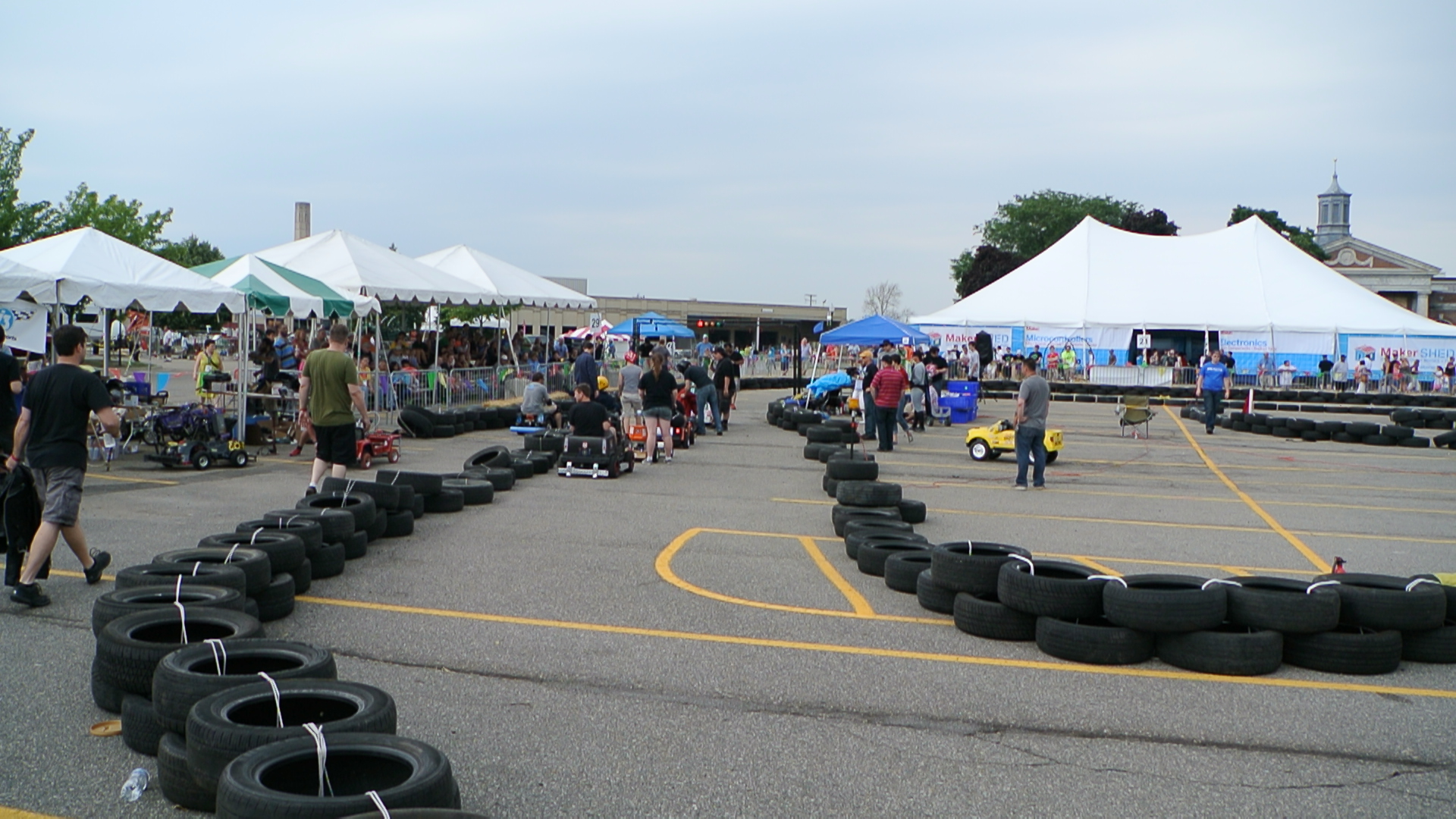
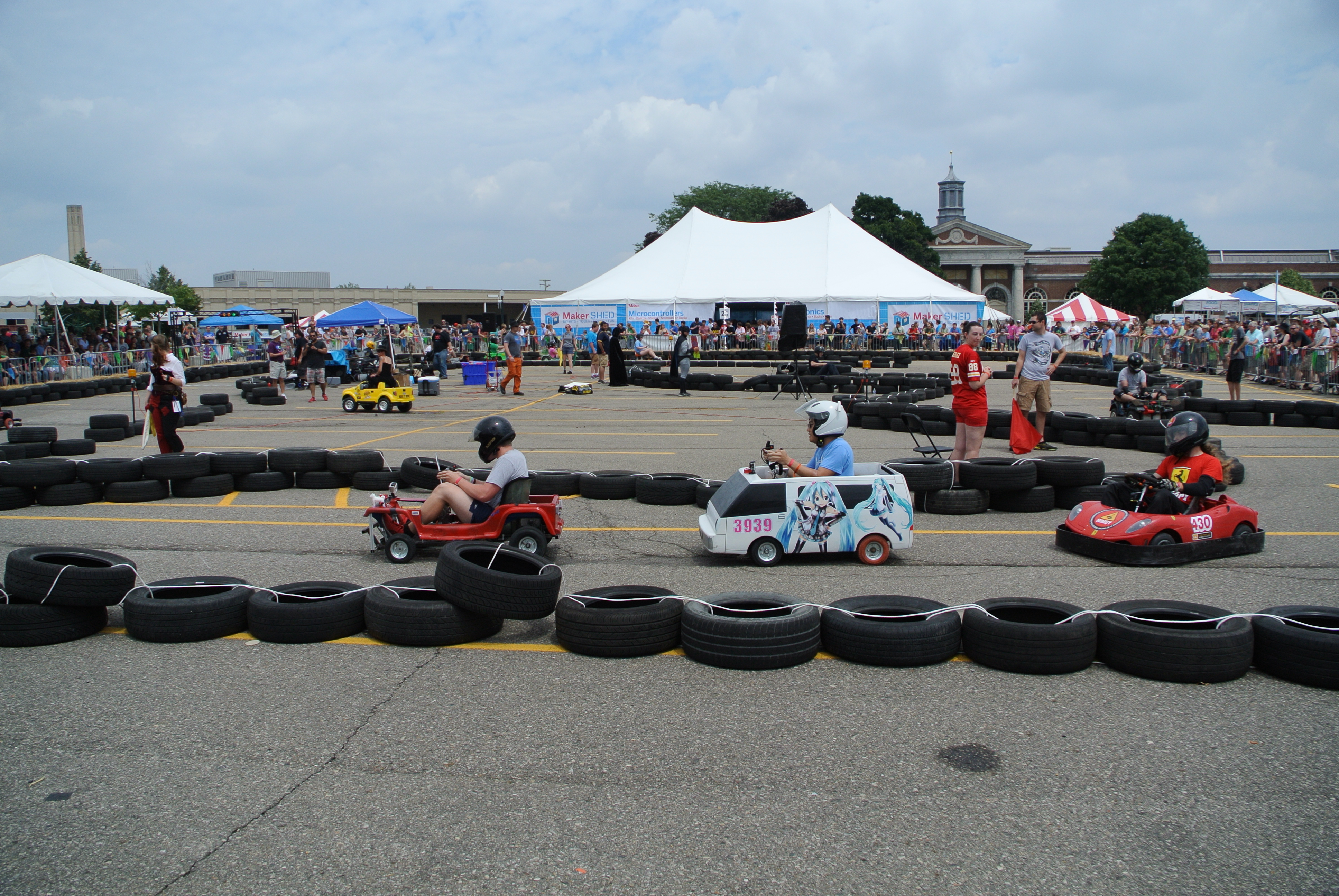
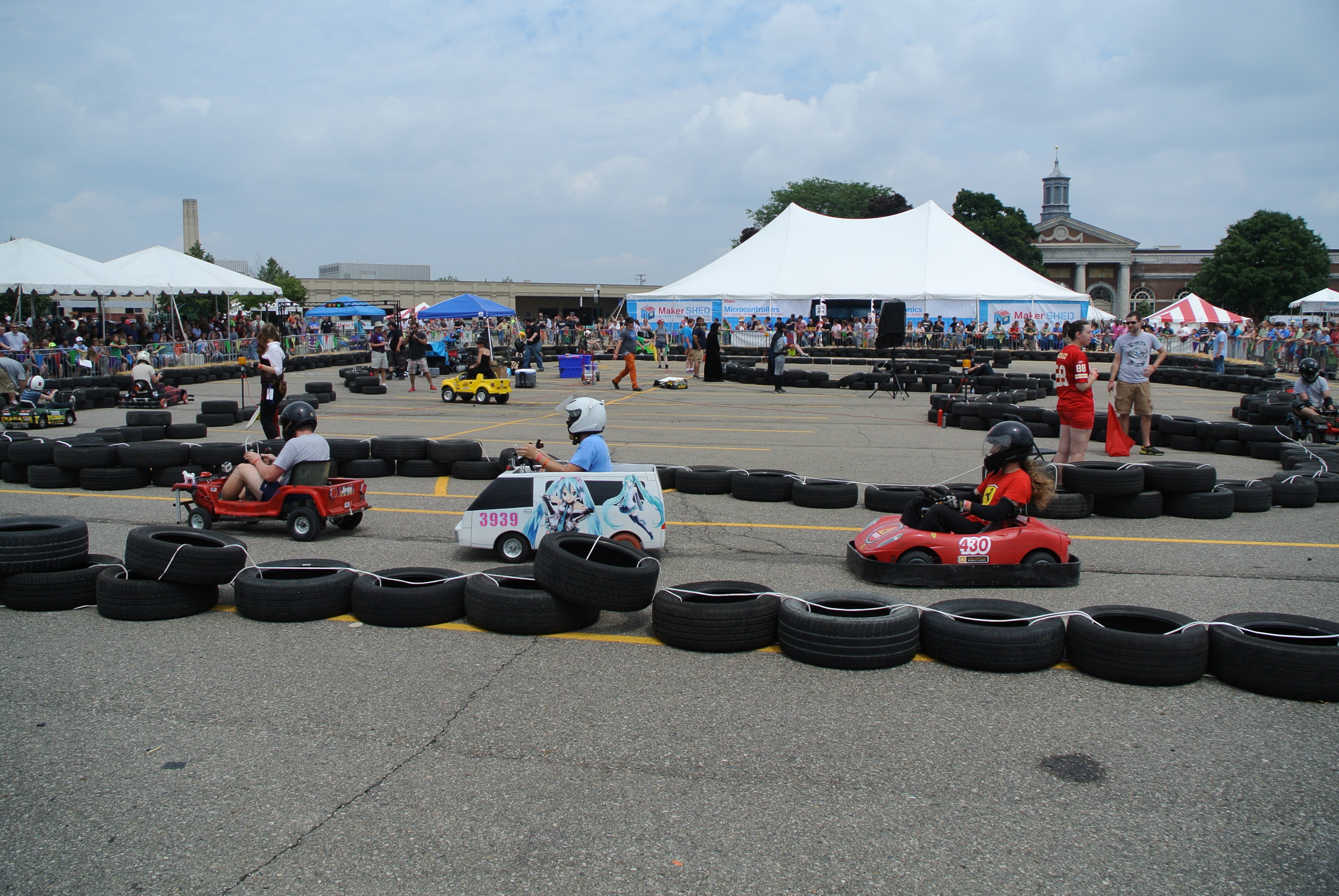
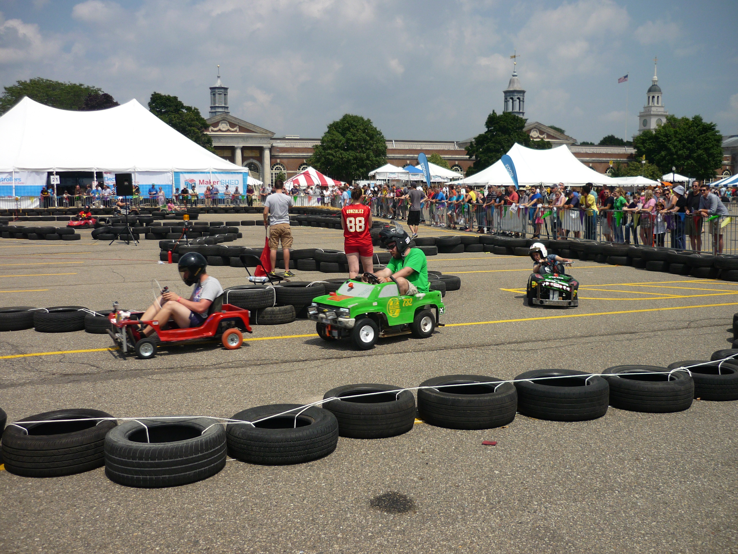
| The
couse and the competitior. The course was huge in comparison to the NY makerfaire of the previous year. They also had a neat tire + rope setup which kept the course together. |
 |
 |
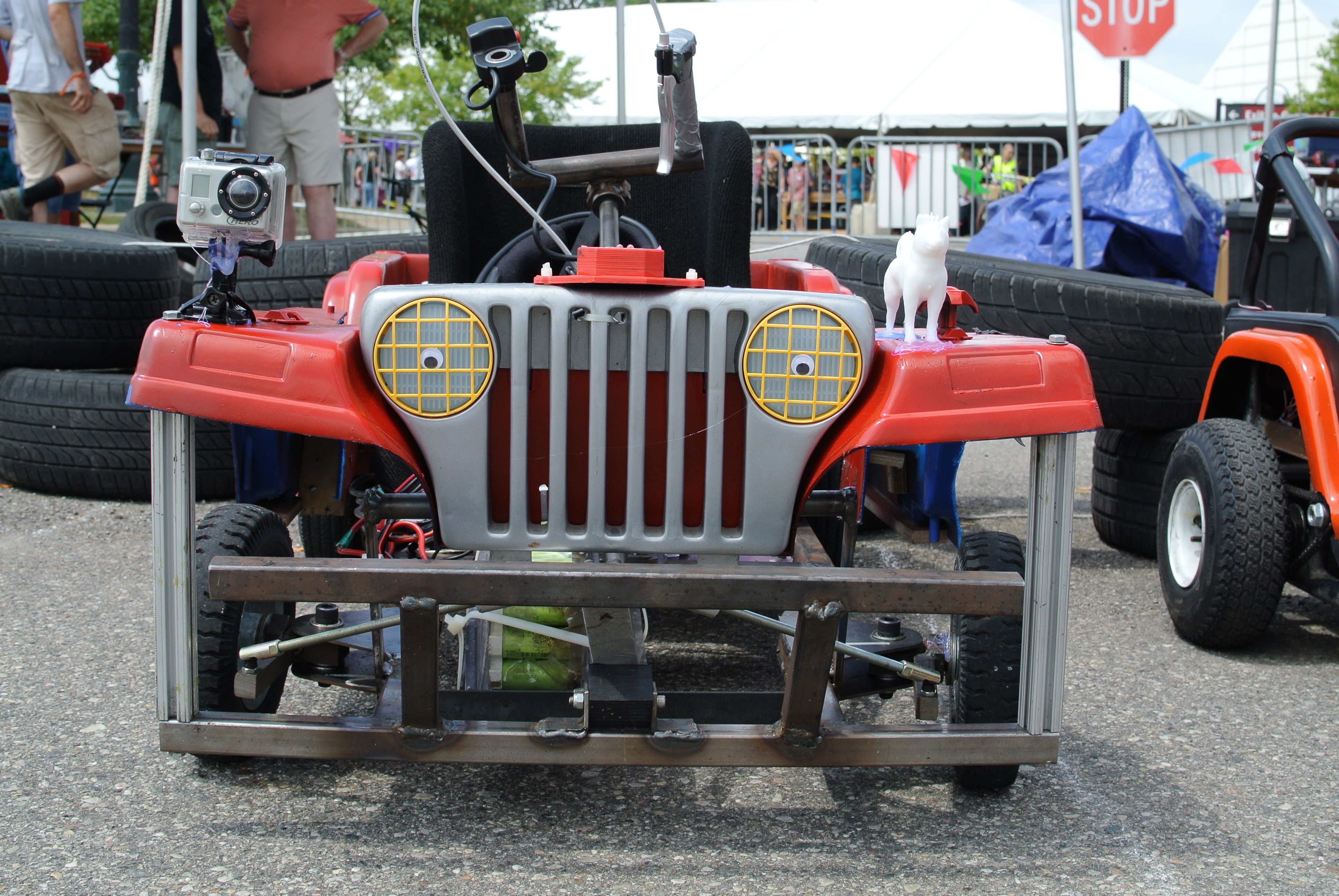
| The
beast armed with a gopro, googly eyes and a 3d printed doge. Chibi-jeep was not taking any prisoners. |
 |
 |
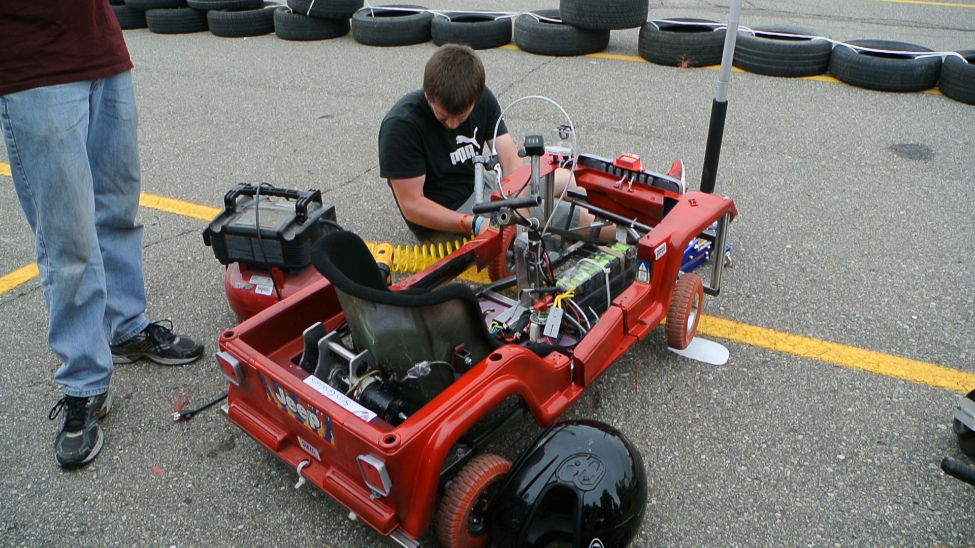
| Pre-race prep The kart was filled with batteires, compressed air and eventiually a driver |
 |
 |
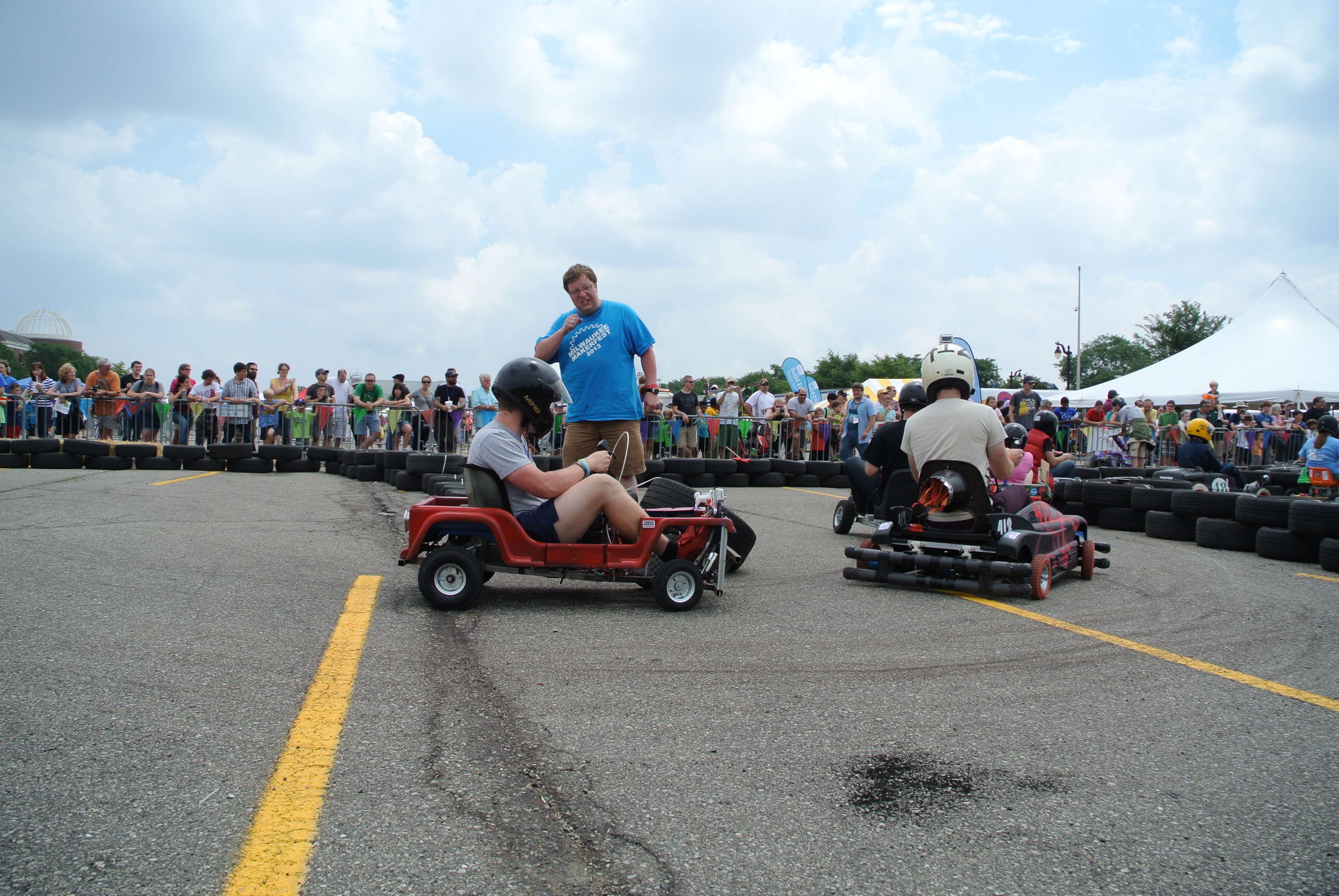
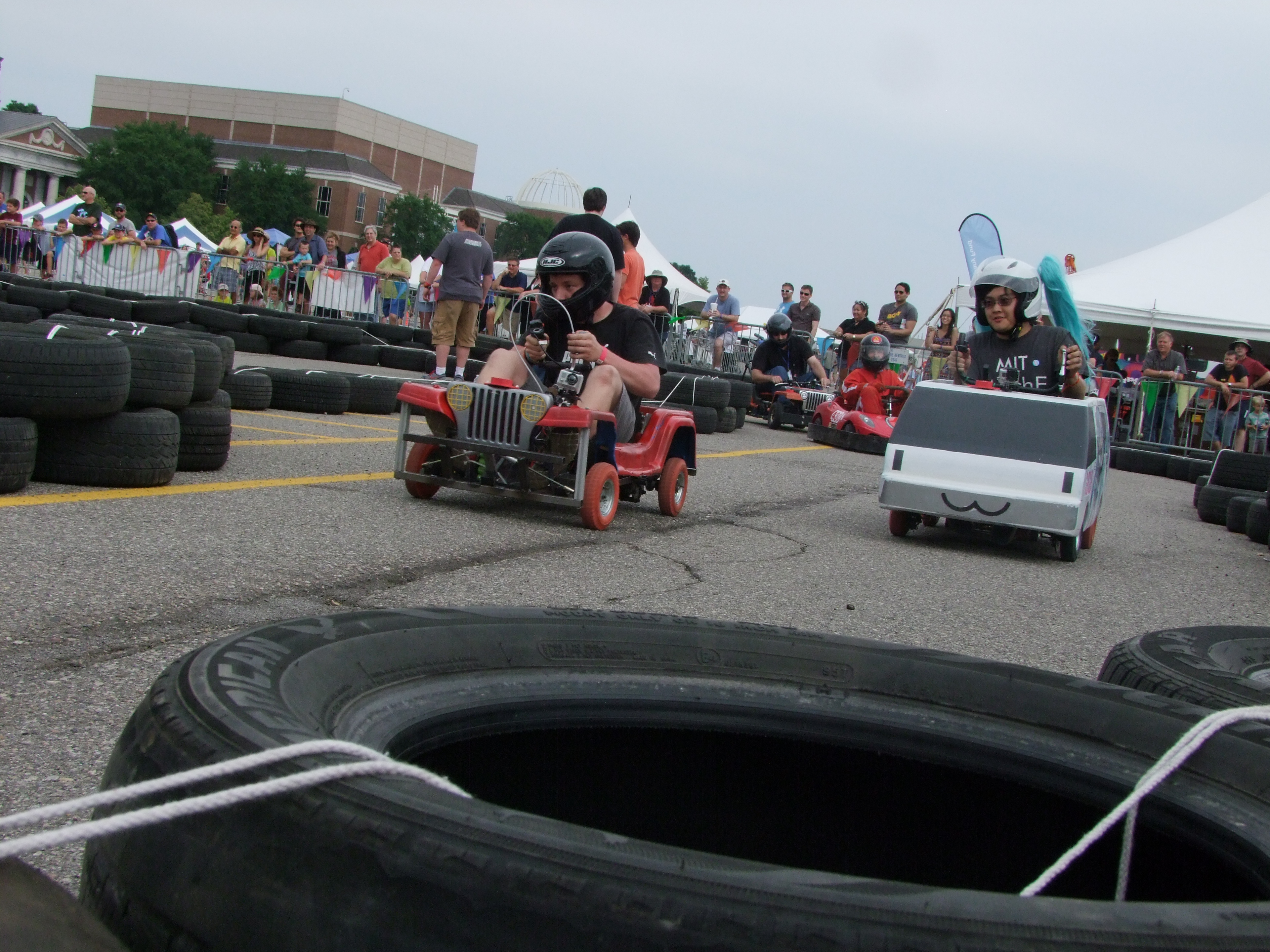
| ENDURANCE
RACE! Ciaran kicking ass |
 |
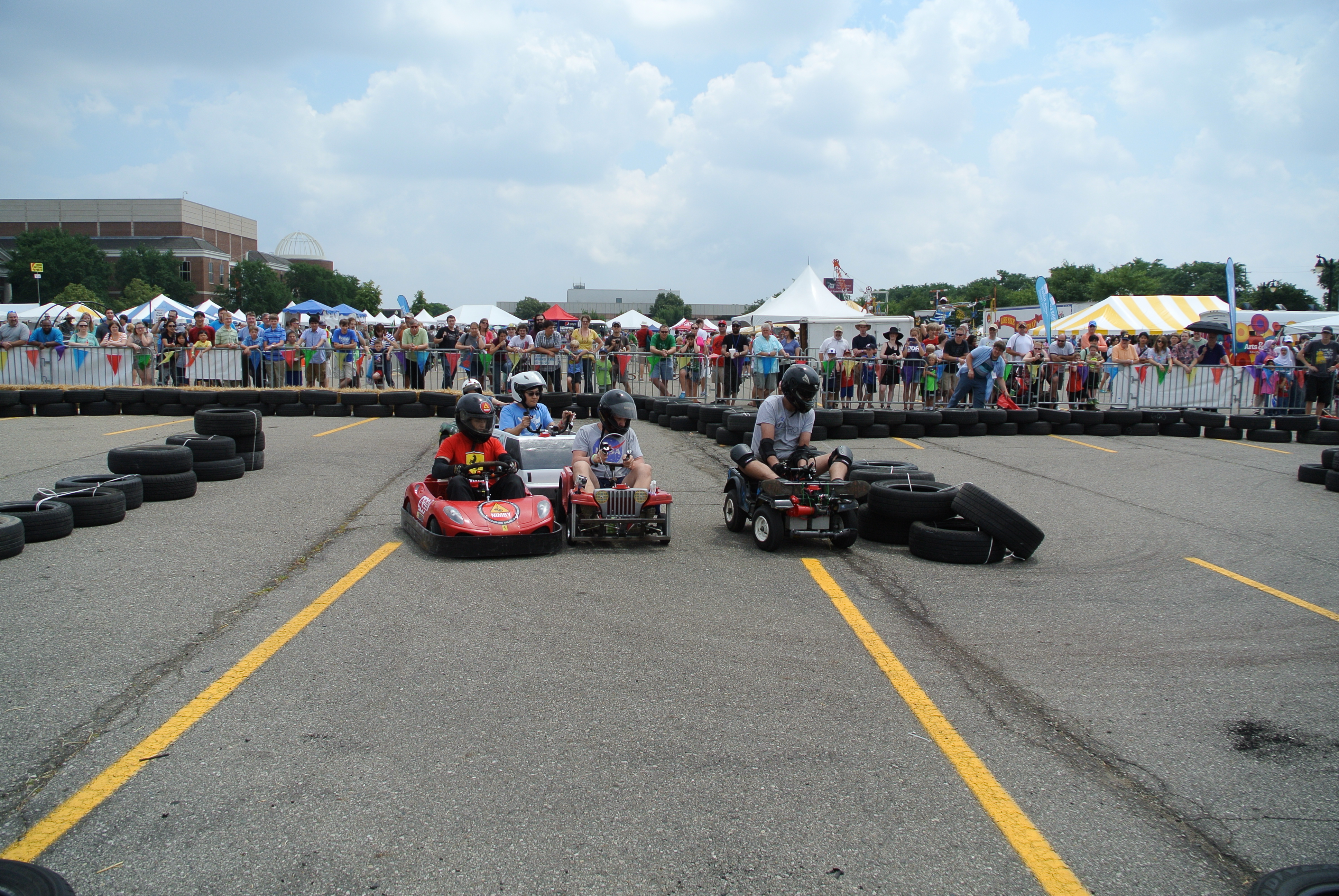 |
| Atomic,
Mikuvan and Nimby all in one shot This is my favorite shot, for nearly a whole lap, atomic-chibi held in front of both nimby and mikuvan, thanks again to magical Ciaran driving skills. |
 |
 |
| Rounding corners, attempting not to detroy the tires. |  |
 |
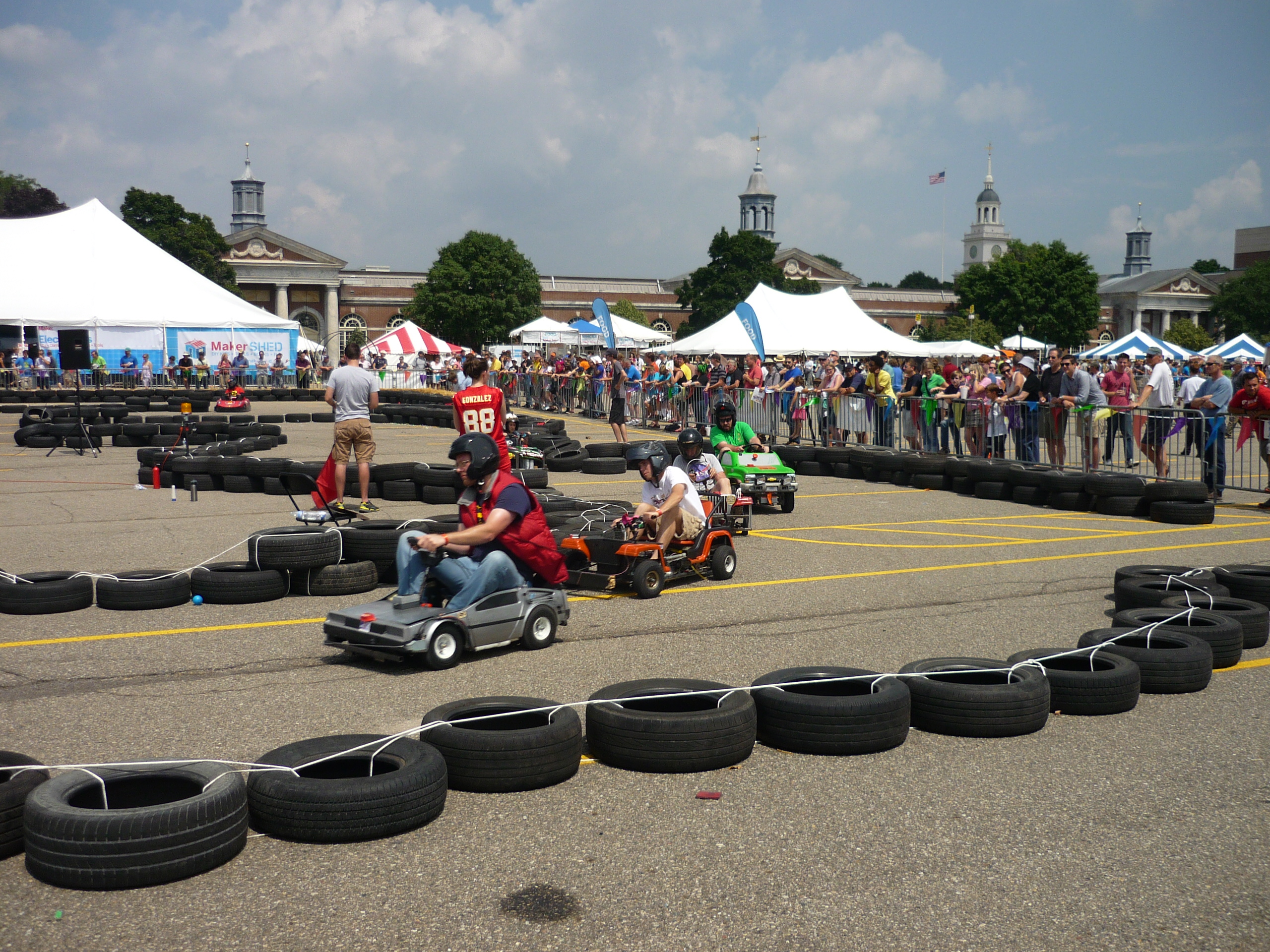
| RACE
RACE RACE DO THE RACE THING |
 |
 |
| ACTION We seemed to burn through tires feverently, we swapped in 2x 10" rear tires for increased speed, only to have them shredded within 4 laps. |
 |
 |
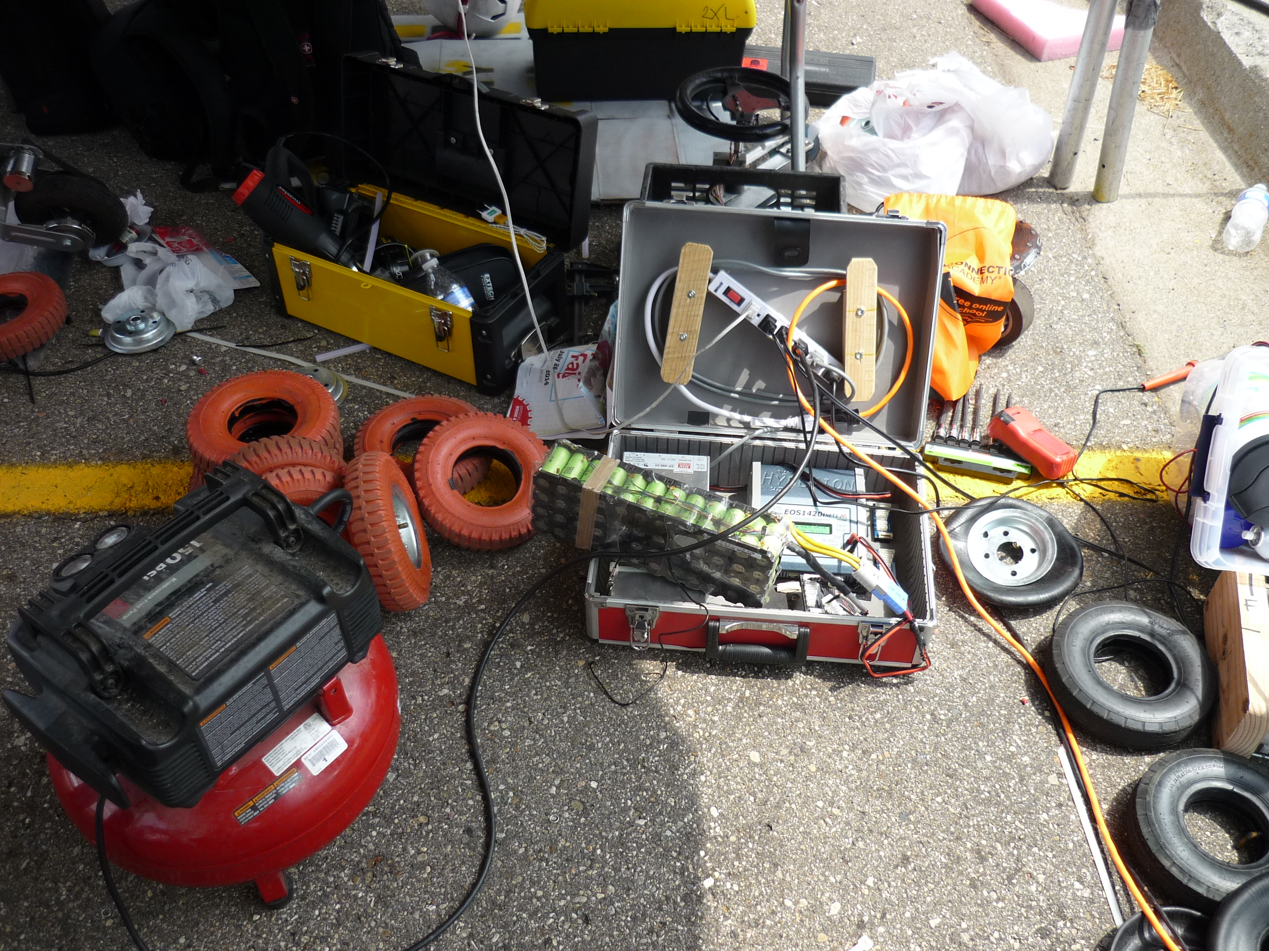
| rage-charging
battery packs (note, same battery pack as the ice-scooter) Hyperion 1420I shown in the background, pumping 500W into the recently discharged pack. |
 |
 |
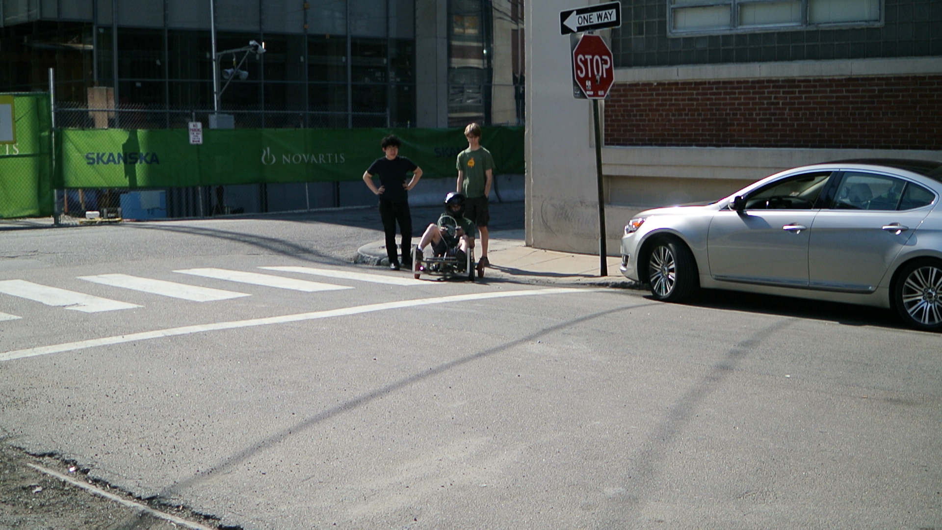
| After-race
putzing around an Audrey and becca enjoying the glorious chibi-atomic-jeep |
 |
 |
| Pit Crew Action | Image / Media |
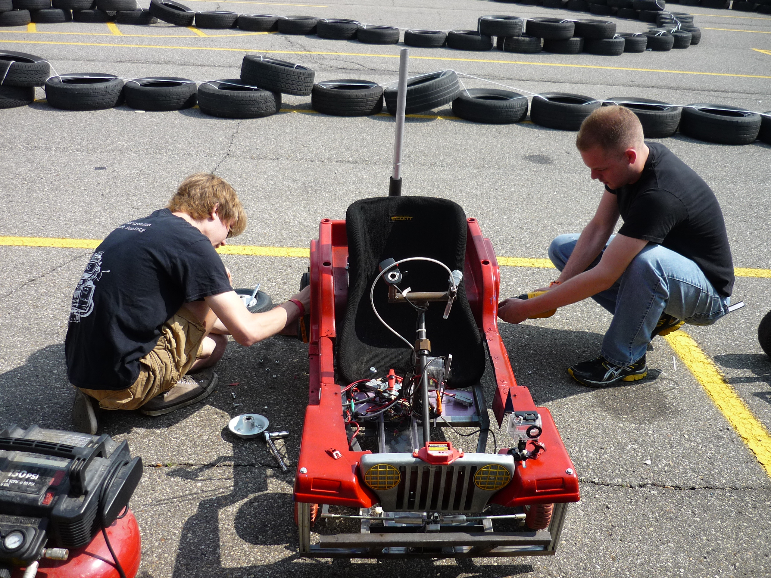
| Tire
changing and battery swapping were hyper-quick. The scooter packs (12S4P, 26650) with 50A anderson connectors proved to be super-useful, as they could be swapped in / out within 10 seconds. Tires were quickly swapped by leaving the previous rim in place and re-inserting a new tire / tube as they fell apart. |
| Endurance Race | Image / Media |
| GO
JEEP GO WE COMPLETED THE ENDURANCE RACE WITH A WORKING VEHICLE. |
| Loosing a Tire | Image / Media |
| We
shredded the tire-bearing assembly on a harbor freight rim. Fortunatley this was caught on film. |
| Bulletproof | Image / Media |
| WOW
THERE WERE THAT MANY ACCIDENTS while racing you dont notice pileups behind you, but the atomic jeep can be seen
|
| Bill of materials | Price Ea | Price Total |
| Pillow blocks | 11.18 | 22.36 |
| Fuse Holder | 8.95 | 8.95 |
| Hardened rear axle | 19.92 | 19.92 |
| Gearbox Bearings | 8.53 | 51.18 |
| 5/8 Shaft Collars | 1.97 | 7.88 |
| 1/4" Keyway stock (1') | 3.7 | 3.7 |
| Steering rod-ends | 3.26 | 6.52 |
| 1" square steel tube | - | - |
| Pink 8" Harbor freight tires | 7.29 | 72.90 |
| Kelly KBS 48V sensored 3phase controller | 149.00 | 149.00 |
| Blackmellon 3phase motor | - | - |
| Super swanky seat | - | - |
| 12S4P battery module | ~240 | 240 |
|
|
 |
 |
 |
 |
(There's
other photos in the photo gallery)
Concluding
Remarks:- Do it. You can build a competitive kart in a week
- Befriend you're local harbor freight manager
- Dont use those 8" pink non-marring tires.
- Have at least a spare battery
- Bring a pillow
- Keep the kelly restart switch in an easy to reach place
- Jot down excellent ideas created when in sleep deprived states, especially those involving meat
- Take no prisoners, this silly racing series is intense
- Doublecheck that you're steering isnt backwards
- Test the vehicle before going on a 14 hour drive to compete
Overall things went well, we had a routine issue with the kelly controller resetting during racing, however this issue cleared itself when we upgraded to 'fullpower' after racing. Still undetermined issue at the moment. The bearings in the gearbox were sub-optimal and needed replacement with something ABEC rated, the tires is an area of improvement, but quick-changing was good practice. Gearbox noise should dissapate after the new-bearing swapover.
If you have questions or comments, ask below or send over an email.
| Comments: |
|
HTML Comment Box
is loading comments...
|
(be
careful, im not responsible for your incredible acceleration)
Dane.Kouttron
Rensselaer Polytechnic Institute
Electrical & Electrical Power
631.978.1650
