Dane.Kouttron
[10.30.2021] Reverse Engineering
a Porsche Battery
A really interesting 13S
lithium-ion battery module appeared Welcome to automotive 'cruft', a mysterious prototype Porsche battery with a built in BMS, in a gorgeous '48v' 26ah arrangement. The goal of this write-up is to reverse engineer the battery monitoring board, flash on homegrown software and use the existing hardware to integrate with another project, instead of adding a battery management board to a module that already had one. This process can be applied to a number of other automotive modules for re-purposing. |
| Quick
Overview |
Quick Component Analysis | Checking on Cell Health | Mechanicals | Image Directory |
<I'm
experimenting with a more mobile friendly layout, things may
render weirdly, it's a work in progress>
| Component by component |
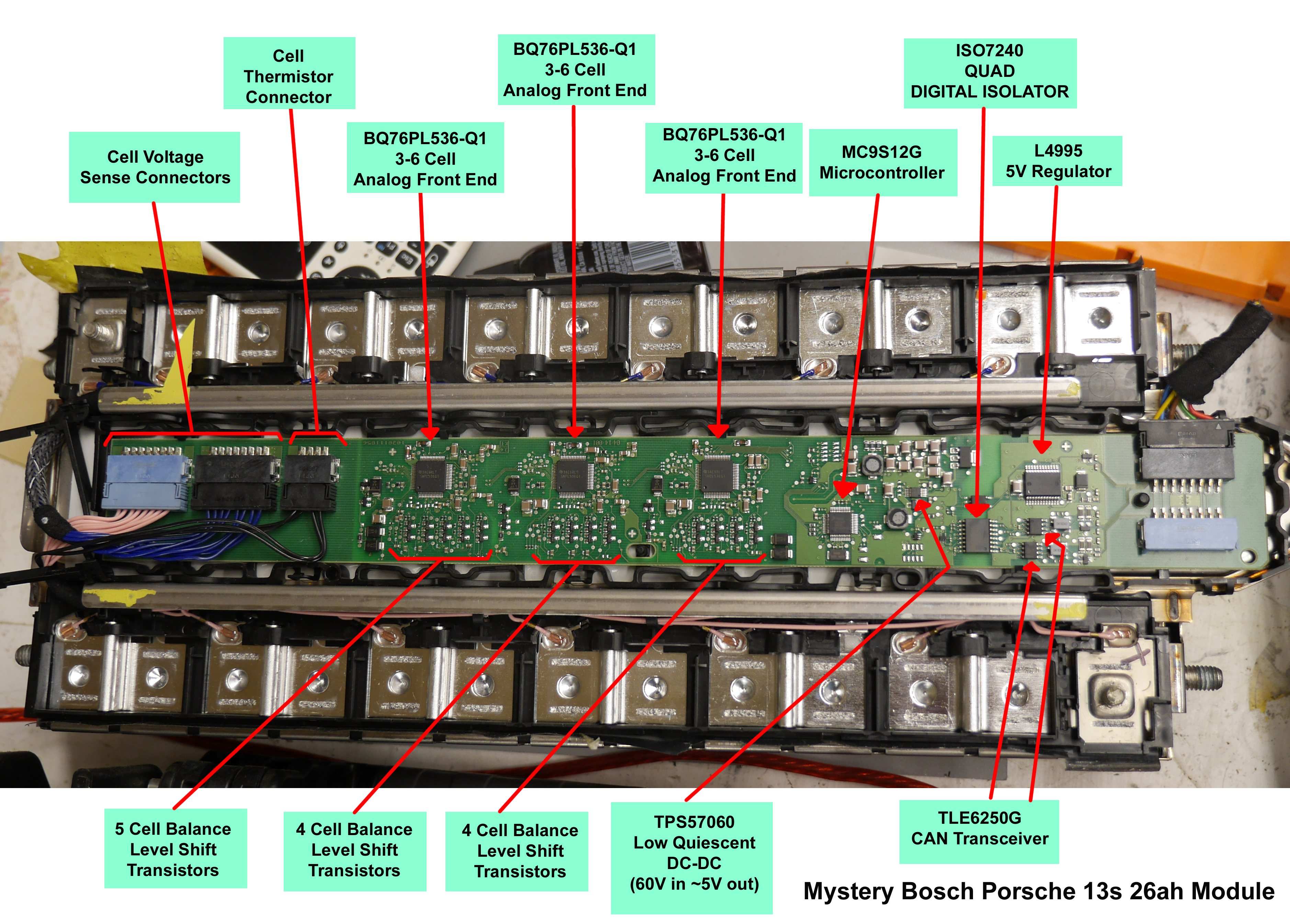
| Basic
Battery Monitoring Overview Most battery monitoring systems are broken down in to three parts, Cell Measurement, Micro-controller that takes actions based on cell measurements, and communications. With these three blocks we can dig a bit deeper to see how that is implemented. |
The TI
Analog Front End The bq76PL536-Q1 is old. This
is a ~2011 analog front end [AFE], rated for 3-6 cells.
Here's the datasheet [link]
and a local copy [link].
Lets check out how it works. This is a really early
'stackable' AFE, you can stack cell groups to make high
voltage packs without having an isolation bus in between
each AFE. Awesome, this means no magnetics no
opto-couplers, just a string of ic's for an indefinitely
high voltage module. You talk directly to the base AFE
over SPI and can glean everything about its upstream
brothers over one interface. What powers each module? The
cells directly. The bq76PL536-Q1 is old. This
is a ~2011 analog front end [AFE], rated for 3-6 cells.
Here's the datasheet [link]
and a local copy [link].
Lets check out how it works. This is a really early
'stackable' AFE, you can stack cell groups to make high
voltage packs without having an isolation bus in between
each AFE. Awesome, this means no magnetics no
opto-couplers, just a string of ic's for an indefinitely
high voltage module. You talk directly to the base AFE
over SPI and can glean everything about its upstream
brothers over one interface. What powers each module? The
cells directly. Note that this is a 3-6s AFE, so you must have at least 3 cells connected. The AFE suggested operating voltage range is 7.2 -> 27v. This seems reasonable but the corner conditions are already starting to creep in. If you have a 3-series cell group that is a bit over discharged (2.3v / cell) , you can no longer read from that AFE or its upstream brothers, the analog front end is asleep. but Dane thats fine like 2.3v is really low. It is for Lithium Ion but for other chemistries (lithium titanate, lithium iron phosphate) 2.3v is a deal-breaker. Lets continue on reading more about this AFE, some notes:
|
MC9S12G
Micro-controller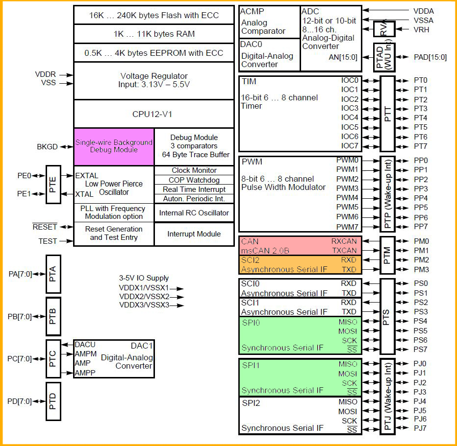 The MC9S12G is part of the NXP "S12"
series of 16 bit automotive micro-controllers. This series
is targeted towards simple automotive applications that
require CAN / LIN communications, sometimes used in
actuators, sensors or even CAN connected lights. The MC9S12G is part of the NXP "S12"
series of 16 bit automotive micro-controllers. This series
is targeted towards simple automotive applications that
require CAN / LIN communications, sometimes used in
actuators, sensors or even CAN connected lights. I'm not as familiar with the NXP series but lets take a quick look to see whats inside. Here's the datasheet [link] and a local copy [link]. We have some interesting things and some slightly odd naming schemes. The only parts I'm really interested in are the Programming interface [Purple] the can interface [Pink] a debug UART/RS232 [Orange] and a SPI bus [Green]. My goal is to develop some incredibly basic firmware for the micro to enable it to just yell out over the CAN bus / RS232 for external hardware to read / data-log. To do this, the nice part is the hardware exists and is all routed. I also have three modules in case one has a hardware issue. |
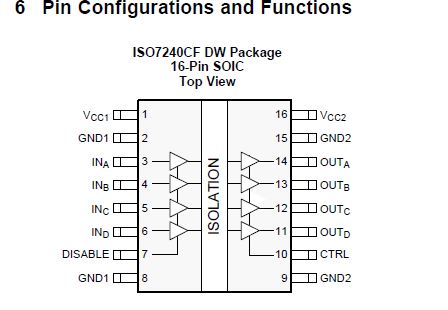 ISO724
Quad Channel Isolation Barrier ISO724
Quad Channel Isolation BarrierHere's the datasheet [link] and local copy [link]. This is a high speed capacitive digital isolation barrier. The ISO724 does not have the fancy isolation power supply built into the par like some of the other TI ISO barriers. It is fairly high speed at 25mbit. Like all isolation barriers, quiescent current is high, input quiescent is ~10.5mA and output is 25mA when data is pumping across. From a cursory view the BMS appeared to have a shared DC BUS (maybe 12v) that fed into that bizarrely packed 5v LDO. Instead of an isolated supply, the battery module feeds the battery side of the isolation barrier. This is somewhat mediocre, 25mA quiescent loading is fairly high, that's 600mAH / day or 4.2AH / week if no sleep-states are present. Admittedly its likely sleep states are used to power down the iso barrier when there's no traffic, more reverse engineering required to sort that out. |
| Some rough pinouts |
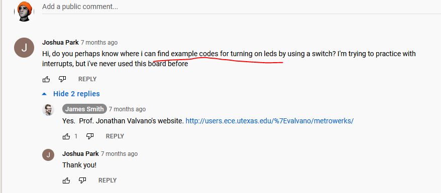
| Lets make sure the cells are healthy before we reverse engineer the BMS |
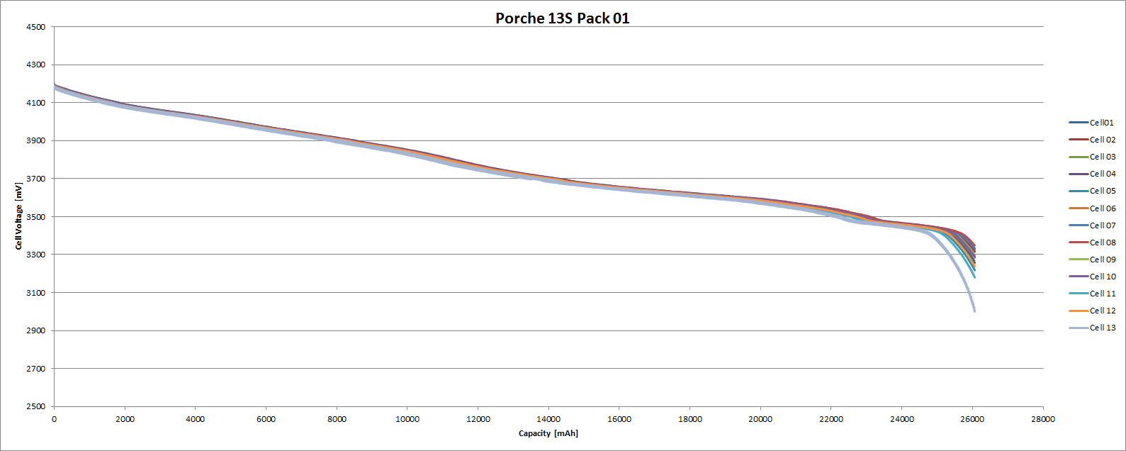 I put the 13S mystery battery module
on the capacity test fixture and grabbed a really
excellent snapshot of the module's state of health. This
plot looks great, the cells aren't terribly different
capacity wise, and the slope is fairly linear. A less
healthy module would have some cells discharging way
earlier than others. The module is 'discharged' whenever
the lowest capacity cell hits its minimum voltage, so just
like a chain, its only as strong as its weakest link. I put the 13S mystery battery module
on the capacity test fixture and grabbed a really
excellent snapshot of the module's state of health. This
plot looks great, the cells aren't terribly different
capacity wise, and the slope is fairly linear. A less
healthy module would have some cells discharging way
earlier than others. The module is 'discharged' whenever
the lowest capacity cell hits its minimum voltage, so just
like a chain, its only as strong as its weakest link. Raw Dataset & plots [xlsx] Note that this module came in at ~26.06 AH, which appears to be its design capacity. |
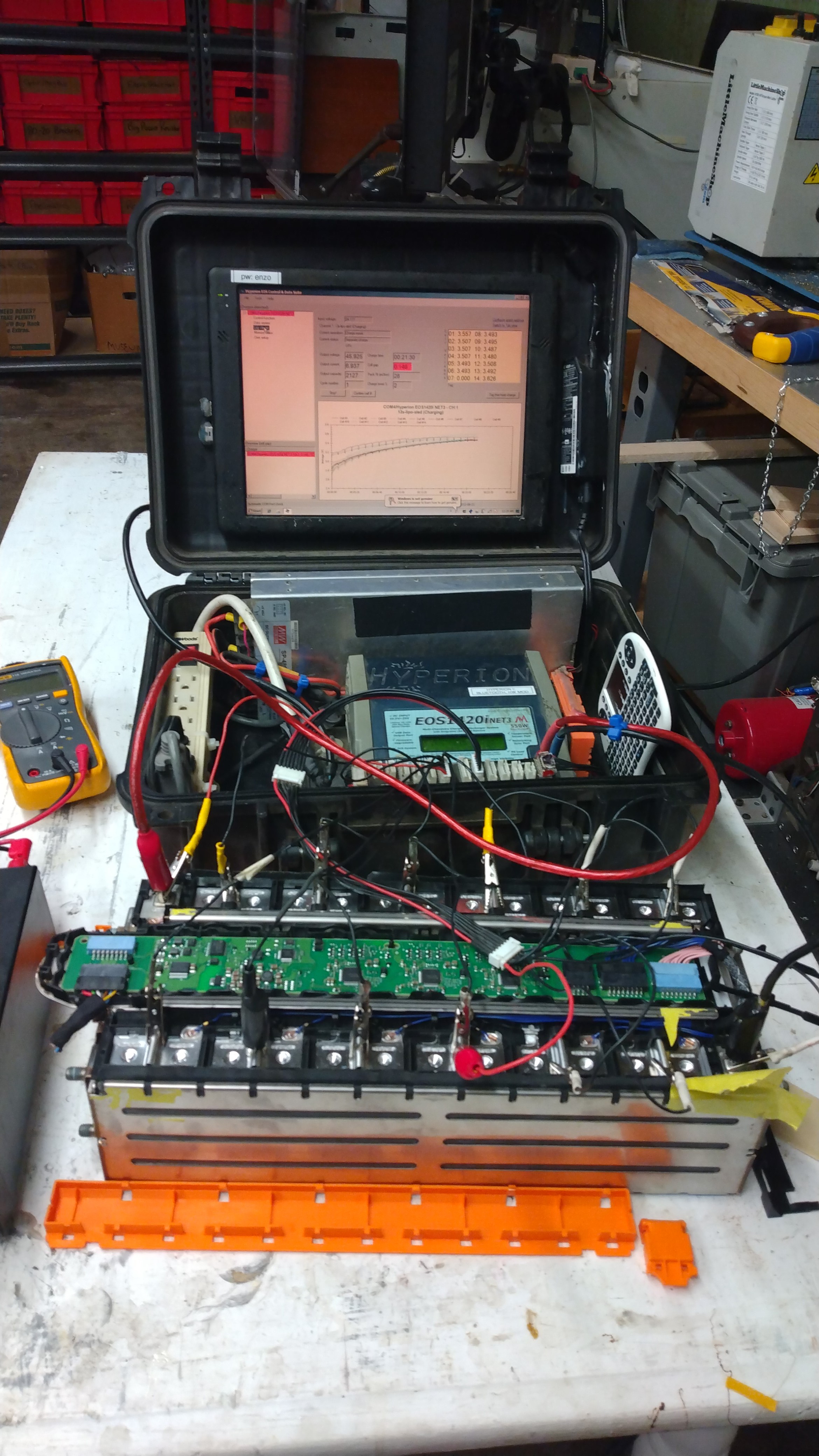 Wait where did that plot
come from? Wait where did that plot
come from? This is my 'battery test fixture' based around the venerable Hyperion 1420i. If it wasn't clear this is a homemade rig with a small windows tablet communicating to the Hyperion 1420i over a bluetooth UART link. To make this plot I manually connect to each cell with a JST-alligator clip adapter. The module is first balance-charged (test fixture is able to do a 400w charge), delay 1 minute and then to automatically discharge and measure capacity. Each cell is sampled every second and written to a CSV file. You can glean from that image just how far apart the cells initially were, this module was fairly out of balance. Note that it is fairly SPICY to have the cell terminals exposed as they are rated for comically-high discharge rates. For the purposes of getting a full understanding, i discharged the module to a 3v cell limit, this is fairly low for lithium-ion however it provides a better indication for capacity difference between the cell groups. |
| Writing
firmware for the NXP Micro |
||||||||||||||||||||||||||||||||
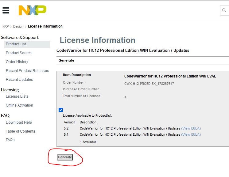 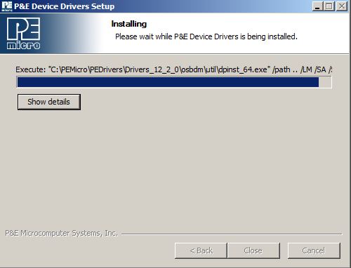 MC9S12G Development Environment MC9S12G Development EnvironmentLets take a look at some NXP quick start guides [link] local copy [link]. The development environment is "CodeWarrior Development Studio for HCS12(X) Microcontrollers (Classic)", otherwise that quick start guide was not terribly useful. To grab Codewarrior, you also need to make an NXP account. I grabbed the evaluation version 5.2 [link] and installed, note you have to use your NXP account to generate an eval license, save it locally as a license.dat. Its not totally clear what the evaluation license restrictions are aside from a 30 day license window. Along with the somewhat long install process, there is a separate installer in the background setting up device drivers. This process took a while, like 12minutes. |
||||||||||||||||||||||||||||||||
 Where the heck are the examples and
demo files Where the heck are the examples and
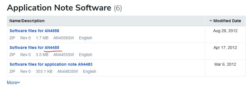
demo filesI may be a bit too comfy with how easily accessible examples and projects are in the arduino community. NXP's demos are somewhat buried in app-notes, this one was somewhat helpful [link] [local copy]. My first goal here is to get the equivalent of 'blink an led' working, compile it without issues and then be able to pump it over to the on-board micro. The sample files are hidden away in a zip folder [AN4455SW.zip]. |
||||||||||||||||||||||||||||||||
 Ok lets start with the ADC example.
OOF this is a lot to just read an adc. I'm already missing
the analogread(x) from arduino land. Getting up to speed
to read the TI AFE may be a bit more troublesome than
anticipated. I need to simplify this a bit to make some
progress. Ideally i want to (in order of importance): Ok lets start with the ADC example.
OOF this is a lot to just read an adc. I'm already missing
the analogread(x) from arduino land. Getting up to speed
to read the TI AFE may be a bit more troublesome than
anticipated. I need to simplify this a bit to make some
progress. Ideally i want to (in order of importance):
|
||||||||||||||||||||||||||||||||
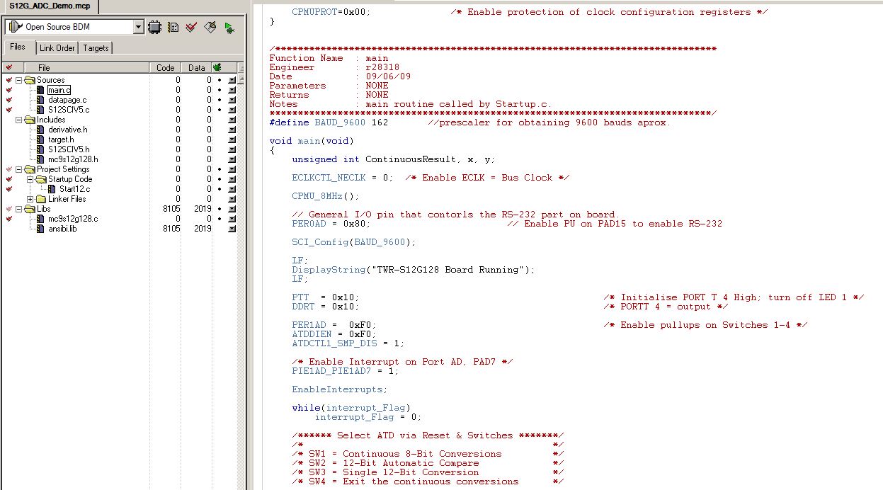
 Comically we see a comment asking
where any example code lives for just blinking an
LED Comically we see a comment asking
where any example code lives for just blinking an
LEDAnd lo, there is the mother-load: [link]. The [very 90's looking] site is titled "Programming the Tech Arts 9S12C32 and 9S12DP512 boards" progress! There's some reasonable intro material hosted there. Unfortunately that's the only video 'James Smith' has up on the 9s12. More digging required. I found [available in archive] [link]. |
||||||||||||||||||||||||||||||||
 While i was digging, I did find a
hint as to where these mystery packs came from.
Check here: [link]
the file name saved the day: While i was digging, I did find a
hint as to where these mystery packs came from.
Check here: [link]
the file name saved the day:"E-Hybrid+Panamera+Battery+Fault-1.jpg". Hot dog! those are the same battery modules! So we now can be somewhat certain these came from a Porsche Panamera E-Hybrid. Ok this is interesting. The Panamera e-hybrid started in 2014 [link] and newer variants are born into 2021. Not sure when the modules i have were born but there's plenty of more digging to do. Kind of exciting, a  ~100k hybrid speedy mobile. Lets see
if there are any more breadcrumbs about this vehicle. It
looks like there were only two batteries, a 14.1kwh and a
17.9kwh. We know the vehicle battery voltage and we know
the cell capacity so lets check. ~100k hybrid speedy mobile. Lets see
if there are any more breadcrumbs about this vehicle. It
looks like there were only two batteries, a 14.1kwh and a
17.9kwh. We know the vehicle battery voltage and we know
the cell capacity so lets check. From [link] we know that the 2019 variant had the 14kwh pack at (nominal?) 382 V. 14,000 / 382 = a 36.6AH cell capacity. So lets make a chart because for whatever reason the capacities for these packs isn't easily accessible:
|
||||||||||||||||||||||||||||||||
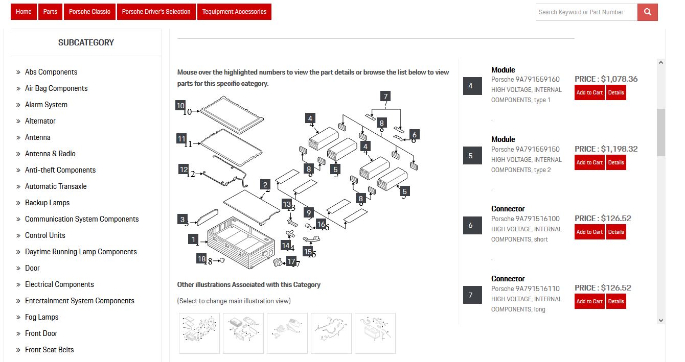 Interestingly the Porsche parts
website [link] shows
only four modules on the 2018 variant. We know that the
pack is roughly 104 cells (380v) nominal so its possible
this is not the right diagram. Either way we have a possible
part number: 9A791559160 and 9A791559150.
We know that the modules we have are 13 cells in
series, maybe there's two layers of what is shown in
the diagram, or (13*4*2)= 104 cells. Ok that's
somewhat likely. Interestingly the Porsche parts
website [link] shows
only four modules on the 2018 variant. We know that the
pack is roughly 104 cells (380v) nominal so its possible
this is not the right diagram. Either way we have a possible
part number: 9A791559160 and 9A791559150.
We know that the modules we have are 13 cells in
series, maybe there's two layers of what is shown in
the diagram, or (13*4*2)= 104 cells. Ok that's
somewhat likely. Well we now have a part number and a likely vehicle. Lets see if there's a service manual or some spicy internet information hiding out there, ideally a wiring diagram. |
||||||||||||||||||||||||||||||||
| Ok so we now know that we
have a 2018 -> 2020 model E-Hybrid module. Lets dig up
the service manual and maybe there's some hints about
wiring / CAN. |
(There's other photos in the photo gallery)
Concluding Remarks:*
If you have questions or comments, ask below or send over an email.
| Comments: |
|
HTML Comment
Box is loading comments...
|
Dane.Kouttron
Rensselaer Polytechnic
Institute
Electrical &
Electrical Power
631.978.1650
