Dane.Kouttron
[09.23.20] Photography Turn-Table
| This |
| What? | Conclusion | Image Directory |
<I'm
experimenting with a more mobile friendly layout, things may
render weirdly, it's a work in progress>
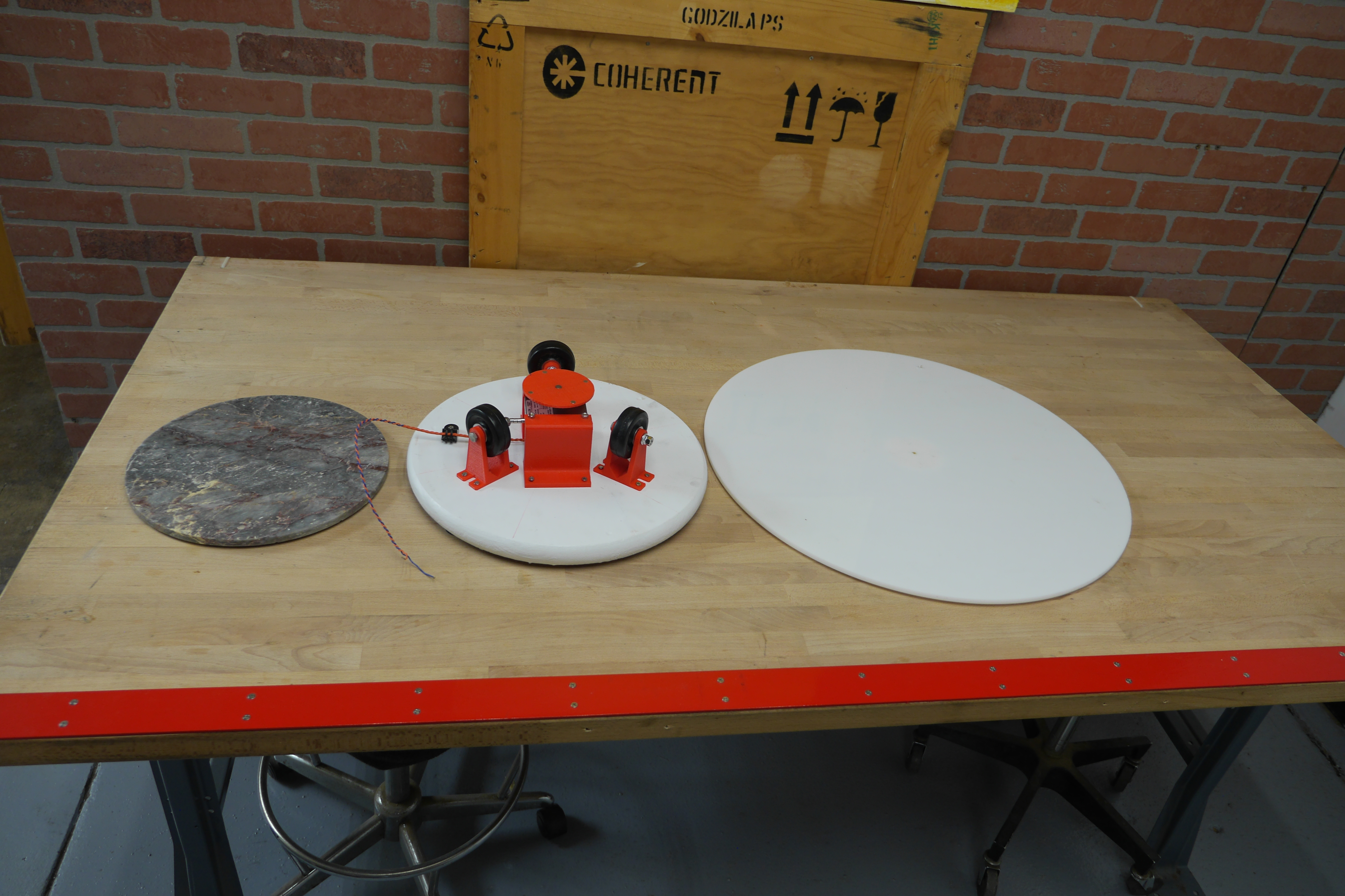
| So lets put everything together |
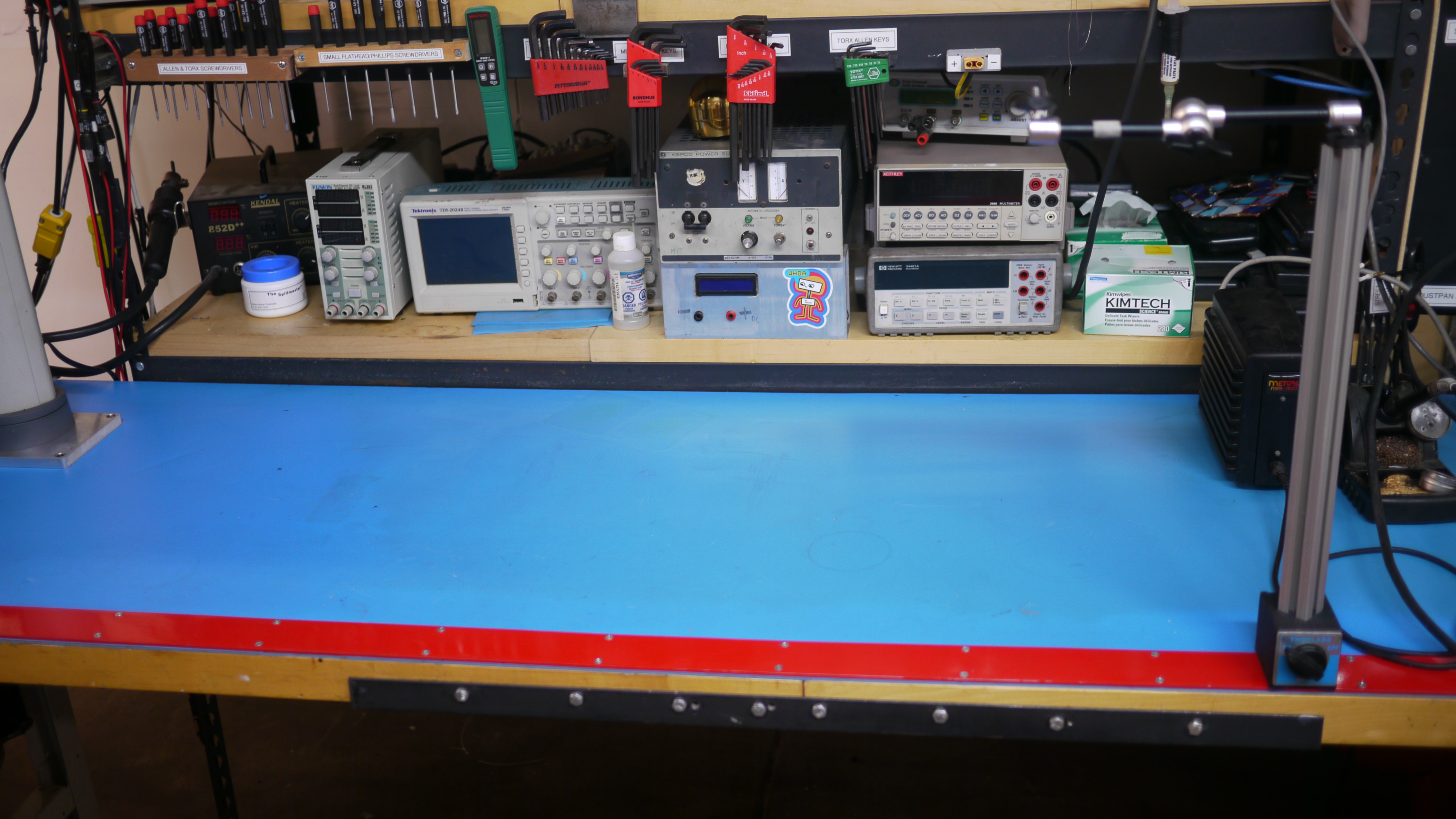 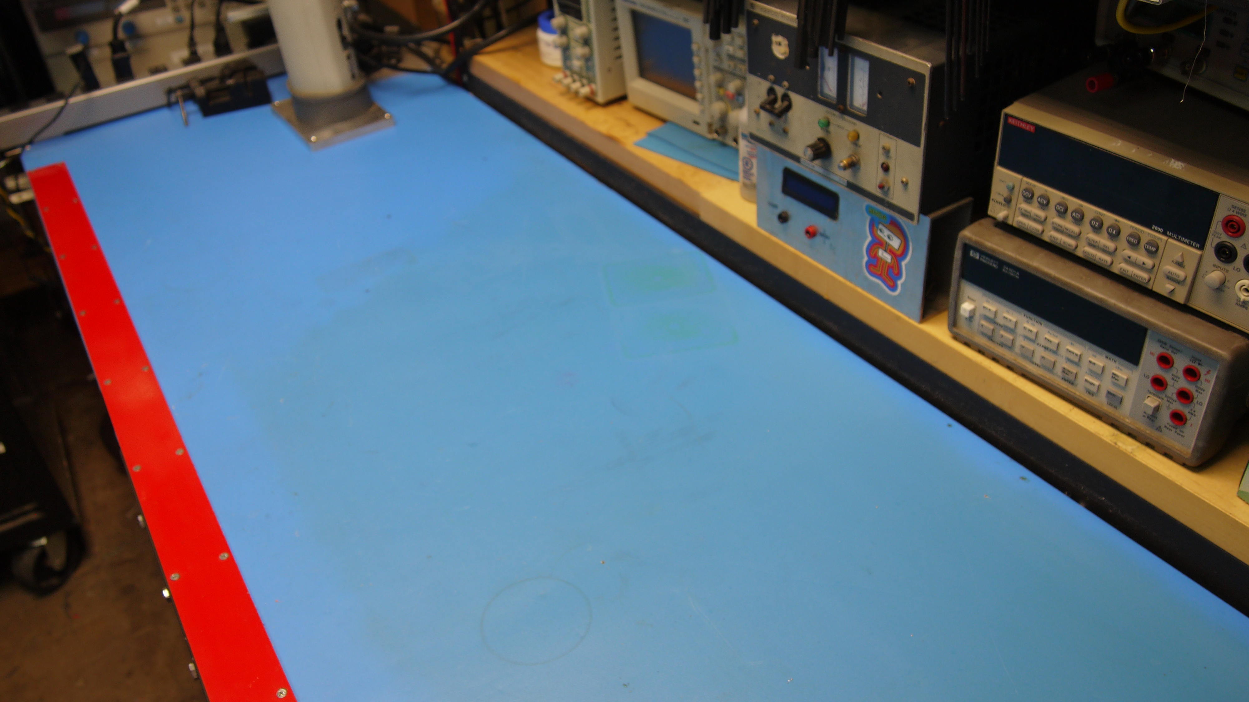 For the first time in a
while I actually cleaned my workbench.
<choir noises> For the first time in a
while I actually cleaned my workbench.
<choir noises> |
  First
step,
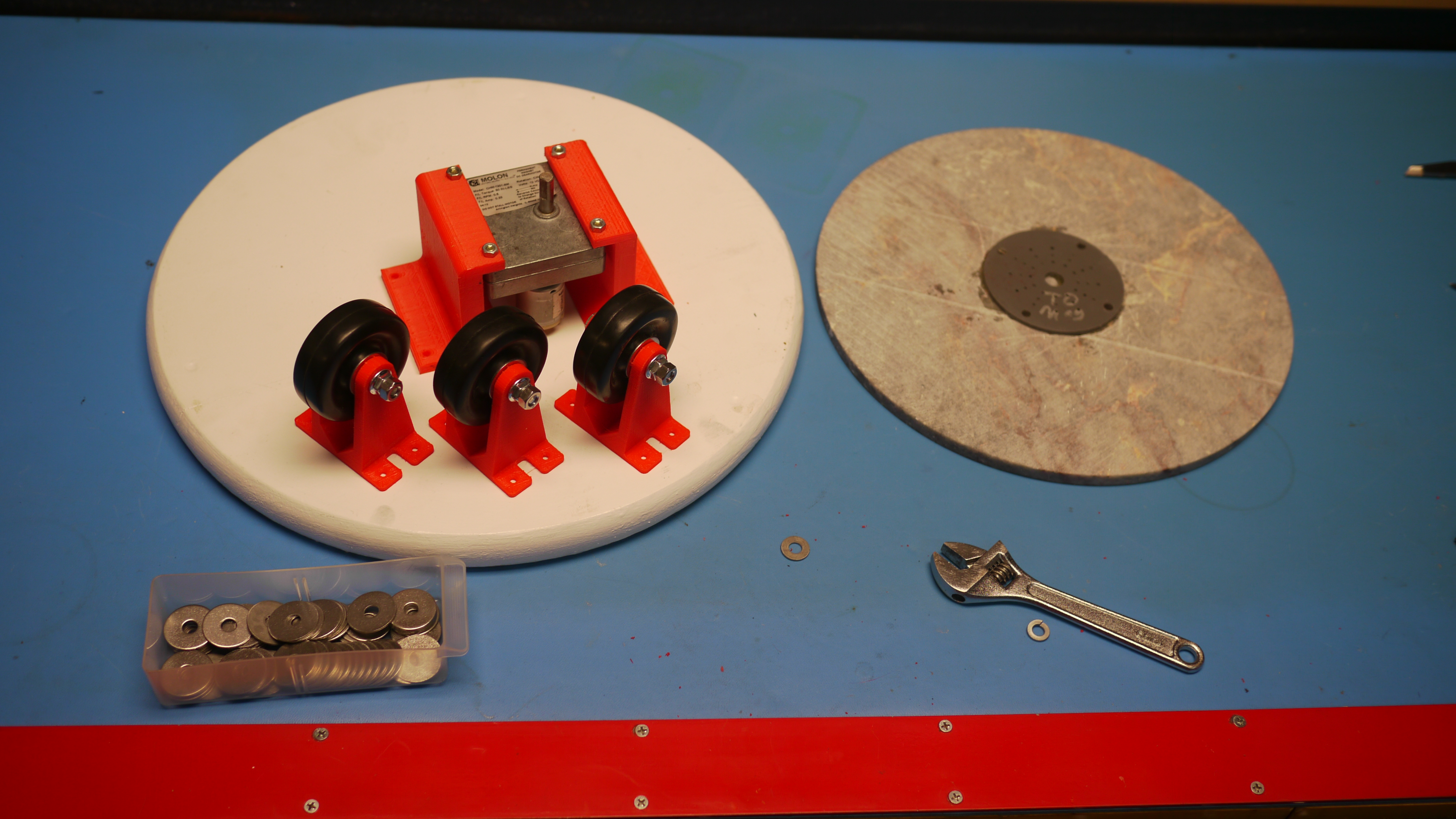
some rollers: First
step,
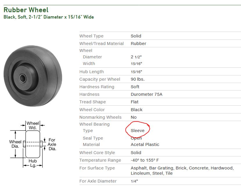
some rollers:For roller wheels, I opted for some quickly-available mcmaster-carr widgets, with a built in sleeve bearing, held up on 3d printed legs. This isn't a high speed contraption, and the largest things I'd probably put on this were in the 20kg range, plenty for a few 3dprinted parts under compression. |
 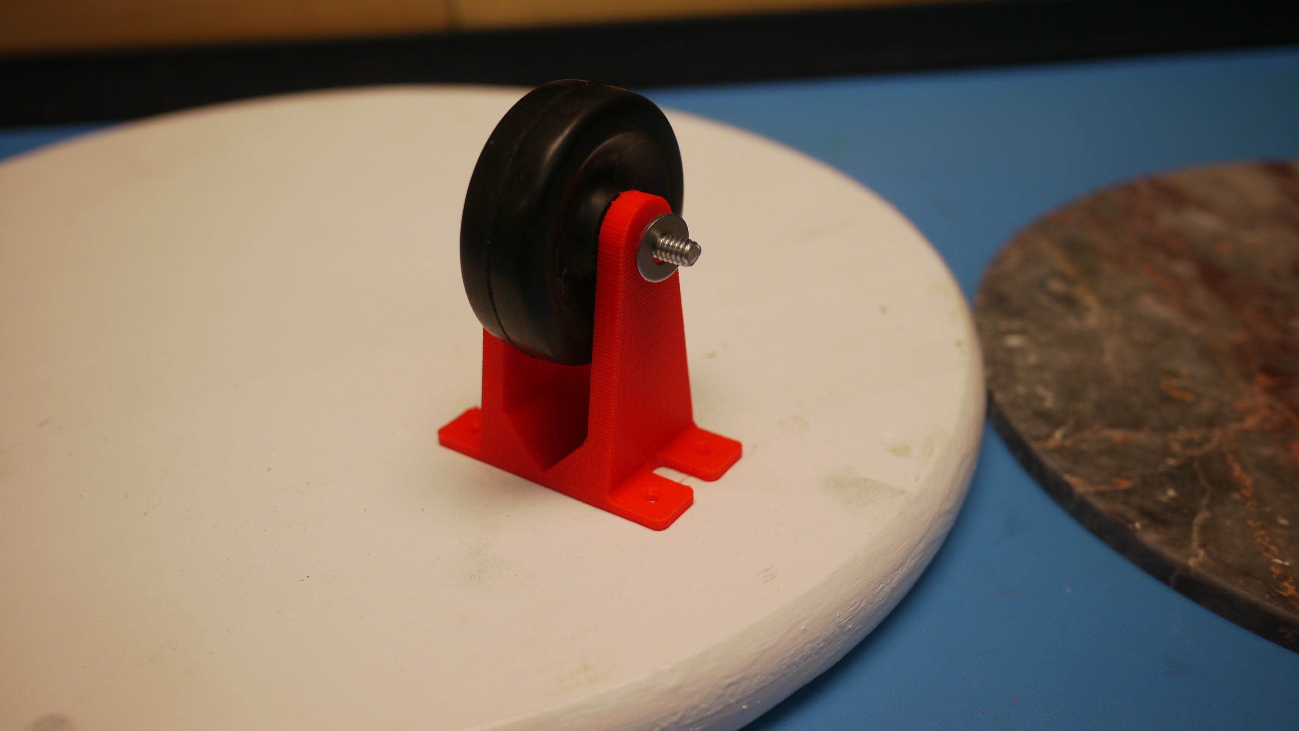 Assembling the
rider-wheels was fairly quick, these wheels are a
simple 1/4-20 bolt, two washers and a nut. An internal
bushings in the wheels forms the bearing surface.
Rinse and repeat twice more and the three roller
wheels are up and running. For a base I used a
home-depot 'round wood thing' that actually had been
my home towel stand forever. I painted it white and
sanded it a bit. Wood is convient, as attachments are
quick and flexible in location. Assembling the
rider-wheels was fairly quick, these wheels are a
simple 1/4-20 bolt, two washers and a nut. An internal
bushings in the wheels forms the bearing surface.
Rinse and repeat twice more and the three roller
wheels are up and running. For a base I used a
home-depot 'round wood thing' that actually had been
my home towel stand forever. I painted it white and
sanded it a bit. Wood is convient, as attachments are
quick and flexible in location. |
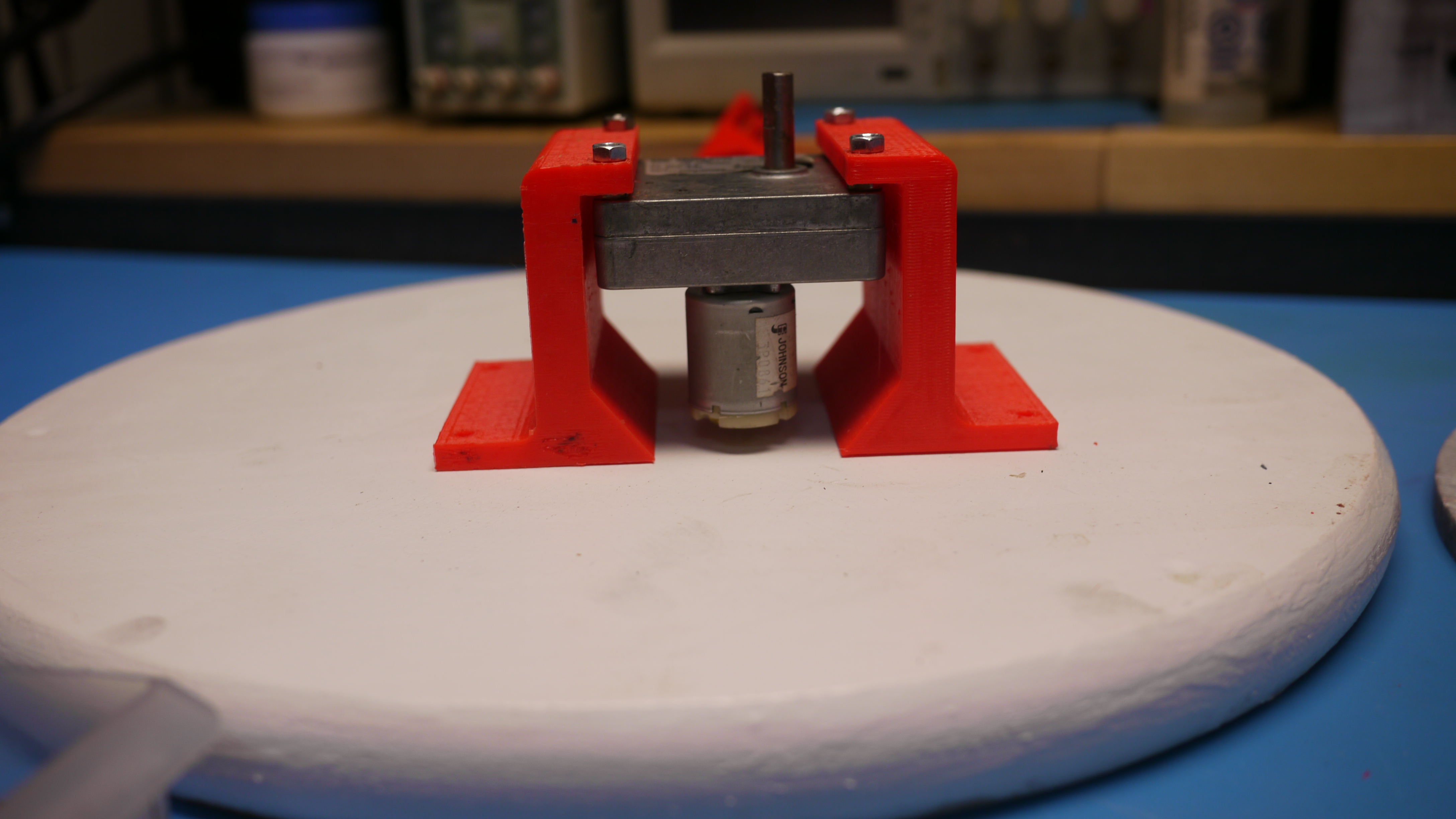
  Time
for a gear-motor and a motor-holster. Time
for a gear-motor and a motor-holster. The gear motor for this project was a random-lab-cleanout widget, 24v ~ 8rpm. I opted for the motor itself to not be the support, just to transmit rotary force, the thought was to design the rollers to sit slightly higher than the center rotary shaft, then trim and adjust the shaft collar that transmits rotary torque to the surface. Either way these mounts are really simple and take advantage of the threaded posts on the gear motor. |
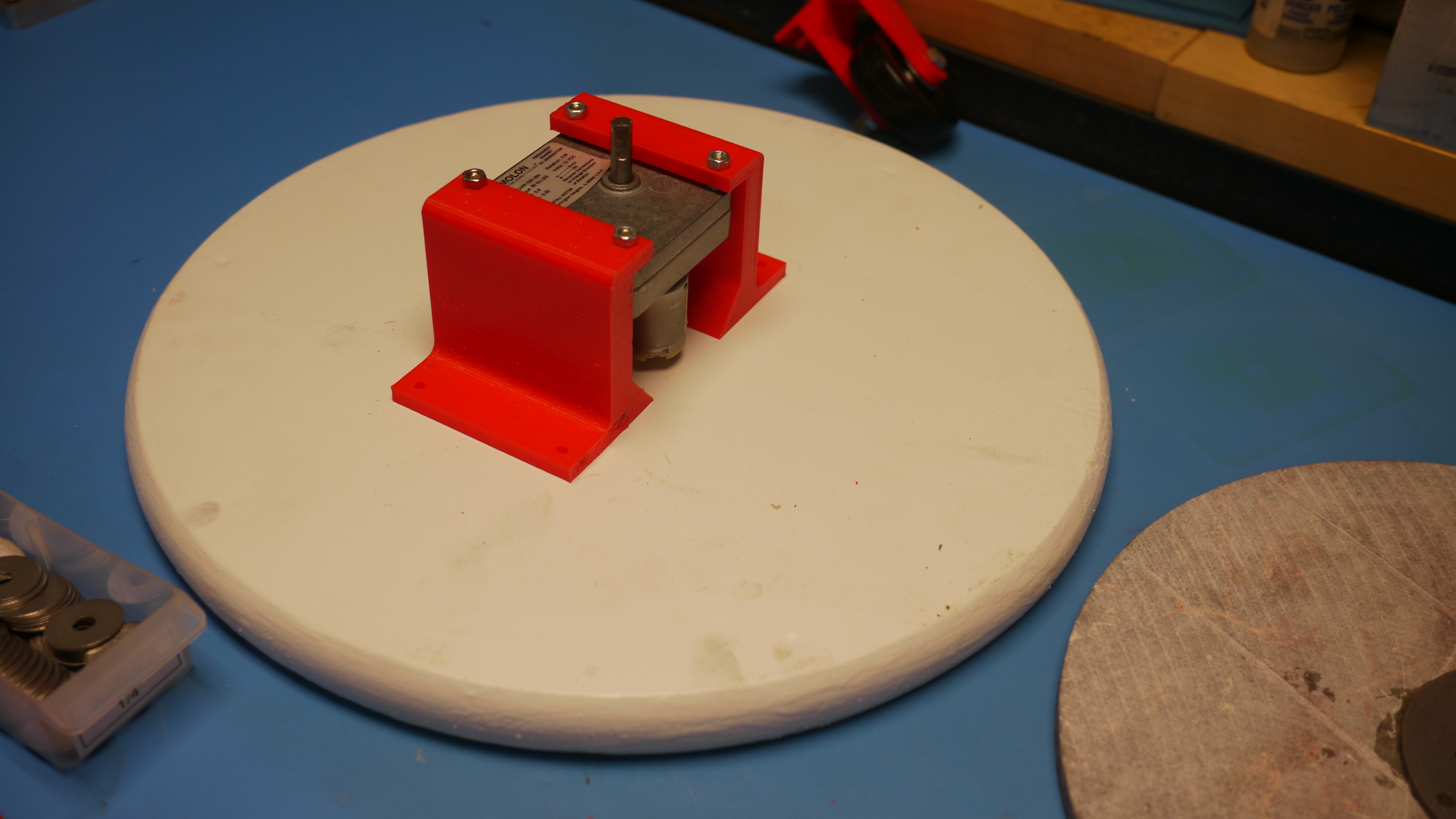  With the roller wheels
assembled, placement of the motor-holder assembly was
up next. Note that the center of the motor-gearbox is
just the output shaft, I took a few tape measure
points to locate the center of the white wooden round.
With the motor mount roughly centered, wood screws
were used to attach it to the base-plate. The motor
hangs from the 3d printed mounts. With the roller wheels
assembled, placement of the motor-holder assembly was
up next. Note that the center of the motor-gearbox is
just the output shaft, I took a few tape measure
points to locate the center of the white wooden round.
With the motor mount roughly centered, wood screws
were used to attach it to the base-plate. The motor
hangs from the 3d printed mounts. |
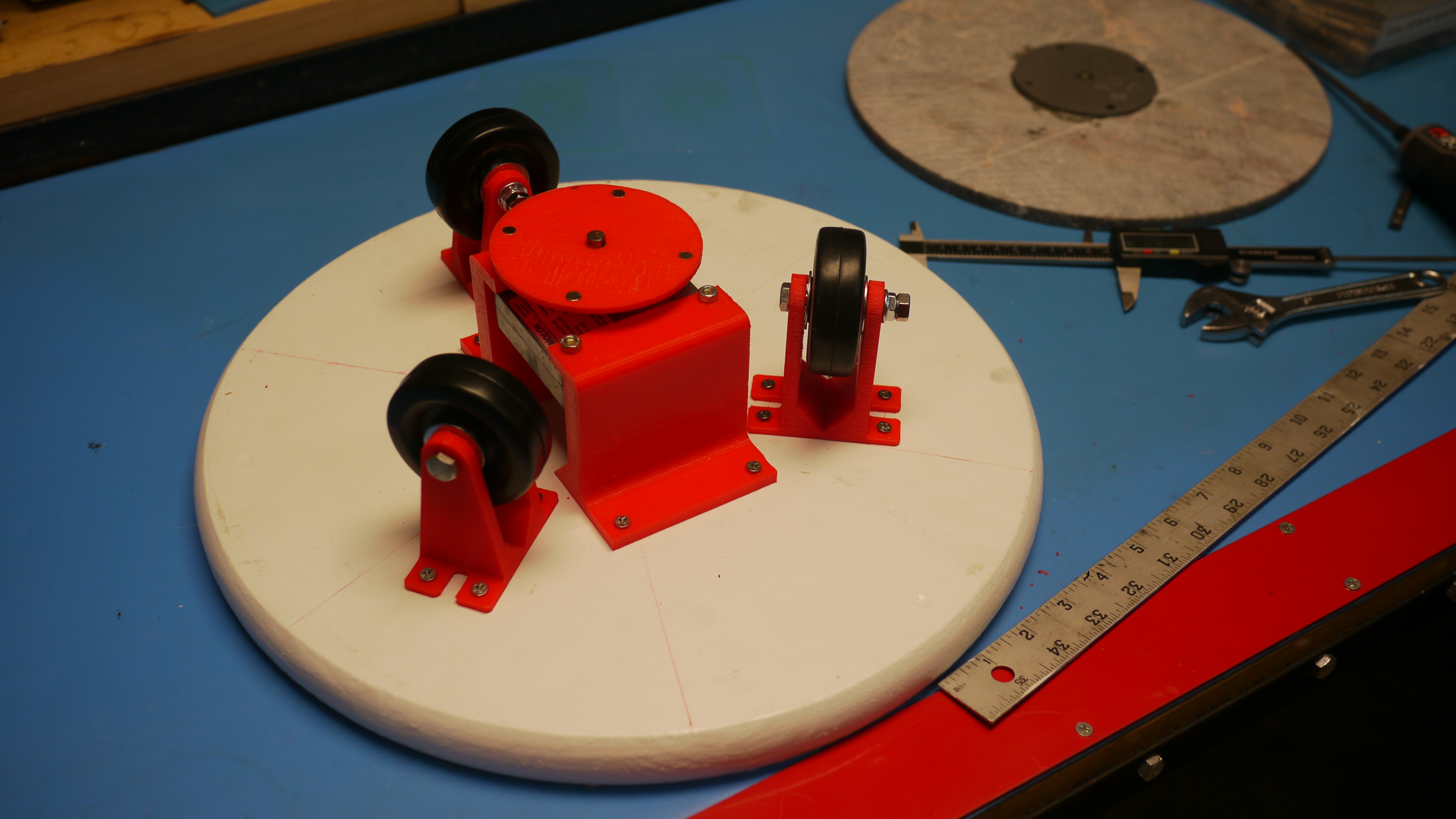
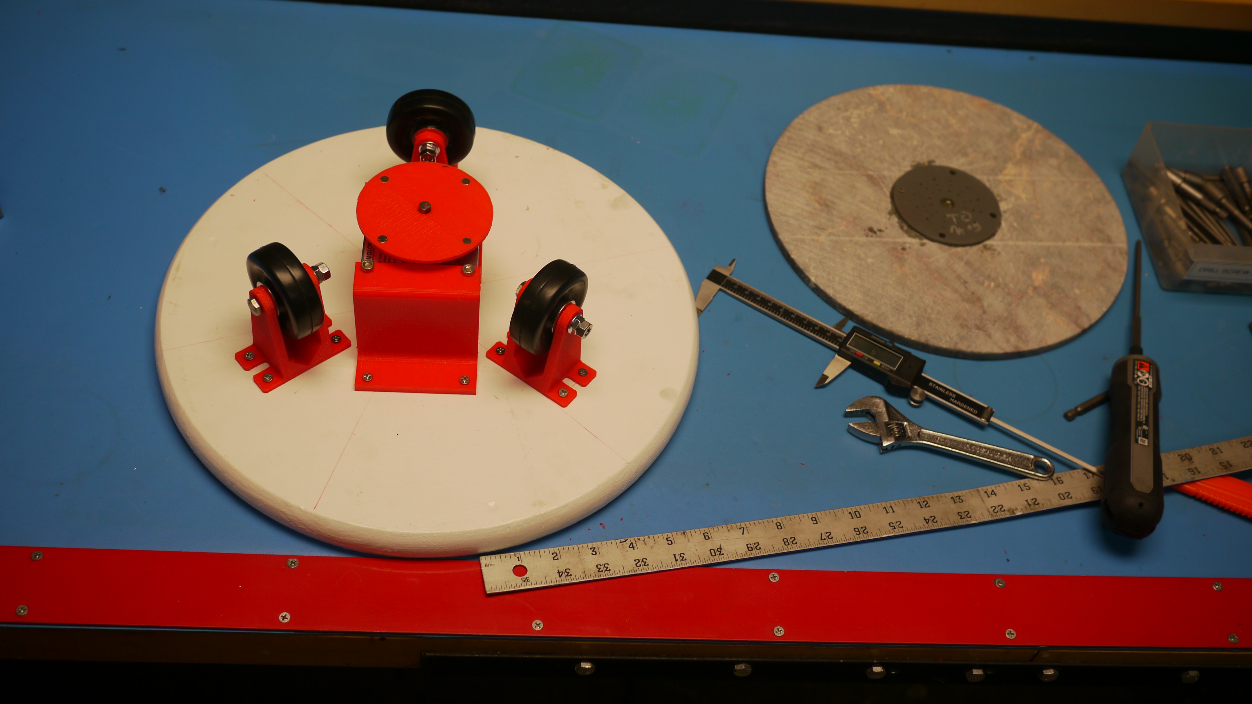
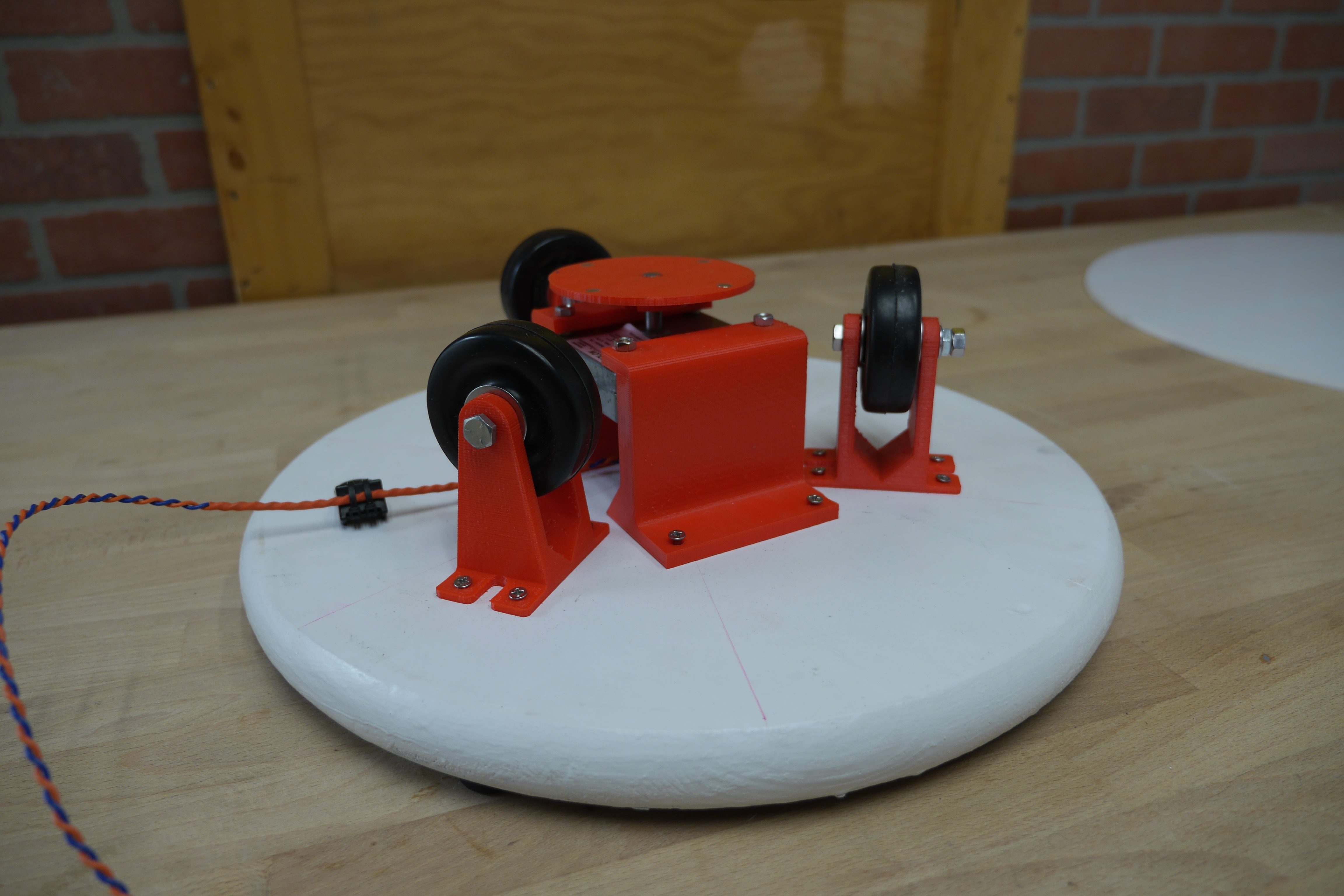
  With
the three wheel assemblies done, it was time to space
them out equidistantly. To do this eaisly i cheated, i
knew the minimum sized rotary disk I'd be using, and
placed one wheel assembly perpendicular to the motor
mount. The remaining two wheels were positioned equally
apart, by taking a measurement between the three. For
each to be 120 degrees apart their spatial distance
would also have to be equal. With
the three wheel assemblies done, it was time to space
them out equidistantly. To do this eaisly i cheated, i
knew the minimum sized rotary disk I'd be using, and
placed one wheel assembly perpendicular to the motor
mount. The remaining two wheels were positioned equally
apart, by taking a measurement between the three. For
each to be 120 degrees apart their spatial distance
would also have to be equal. |
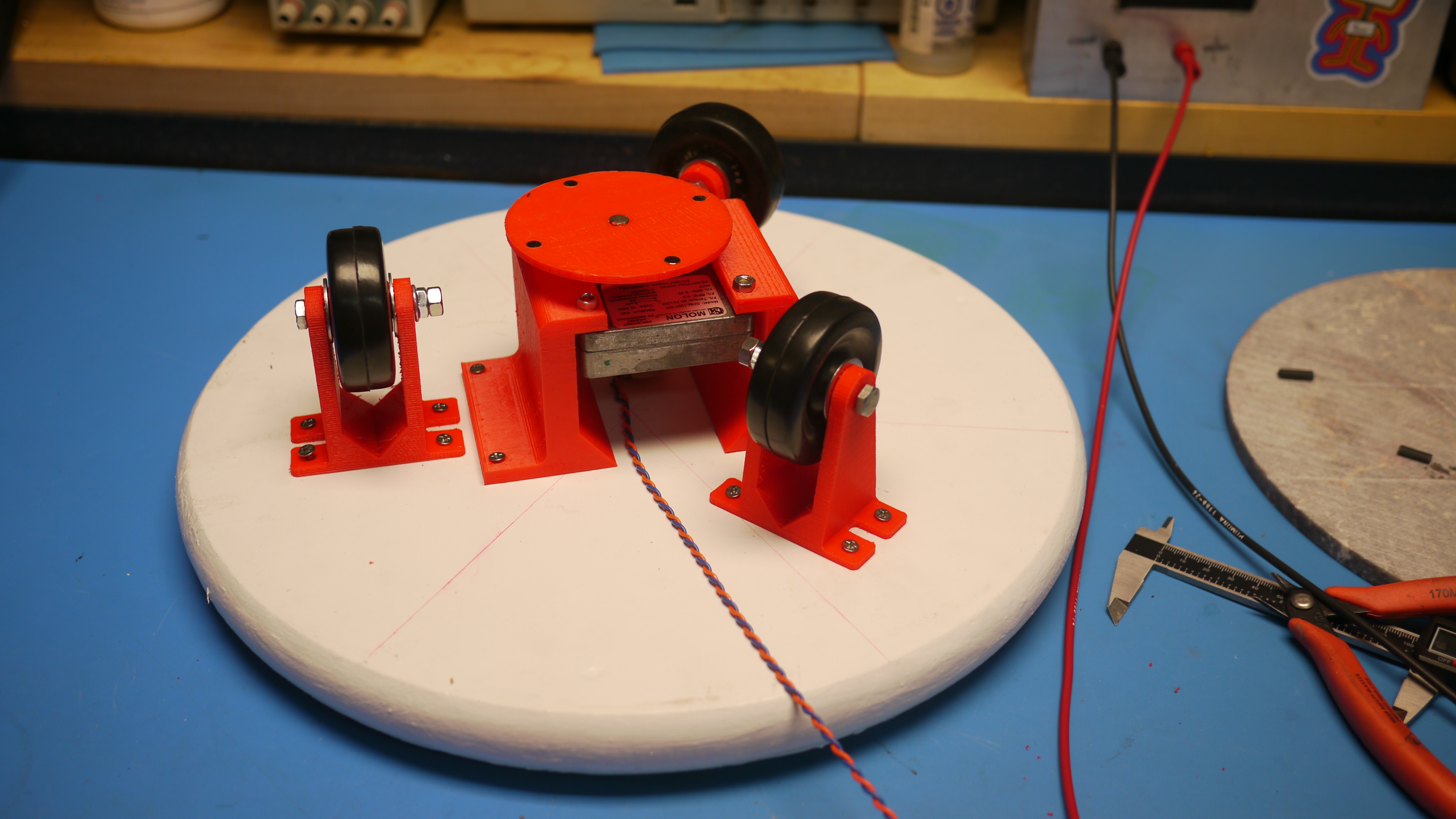
  With
spatially equal positioning, everything is attached
with some stubby 3/4" wood screws. Notice the small
plate on the top of the gear motor? That's the small
magnetic coupler for the motor side. With
spatially equal positioning, everything is attached
with some stubby 3/4" wood screws. Notice the small
plate on the top of the gear motor? That's the small
magnetic coupler for the motor side. |
  Magnetic
Coupler motor side Magnetic
Coupler motor sideMating from the motor shaft to the rotary platform, I chose to use a shaft coupler press-fit into a 3dprinted part. Going with a purely printed part would probably end in headaches as the small 8mm shaft D-shape doesn't provide a lot of contact area. Shown in the animation is the 3d printed part, shaft collar and magnets not shown. |
 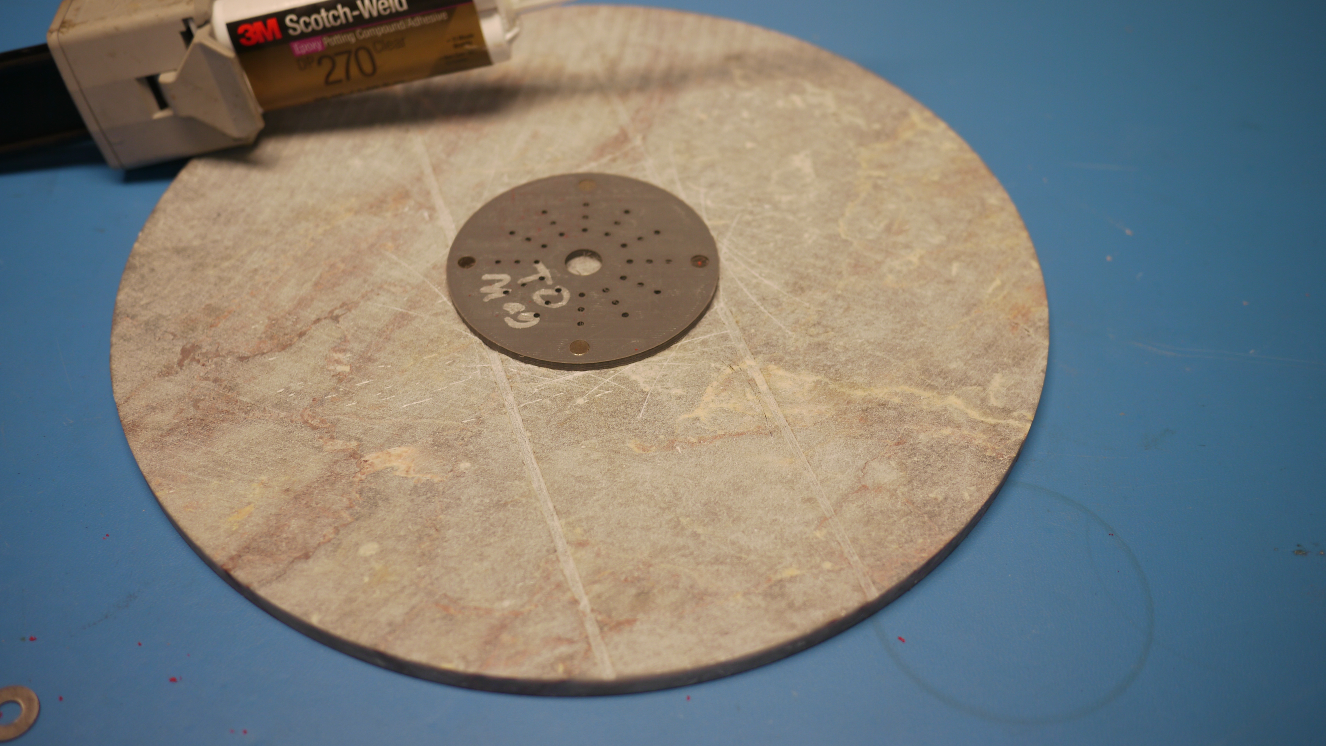 Magnetic Coupler rotary
table mount Magnetic Coupler rotary
table mountTo allow easy changing of the rotary platform (lets say I want to use an different color / material) I opted for a magnet mount to mate to the platform of choice. Four magnets, each set for north facing one side, are pressed in, the remaining holes are extra contact area for epoxy to mate with the rotary table surface. You can choose whatever epoxy works for you, I like the somewhat compliant DP 270. |
 Epoxy Time Epoxy TimeThe carrier for the rotary table is magnet-coupled. This has a benefit of being removable (can change the color of the rotary stage) and also works as a way to prevent jamming, if for whatever reason the rotary platform gets snagged it will just mechanically de-couple not destroy its gearbox. DP270 was used to adhere the printed part to the table. Small 1/4" magnets were used, each facing the same direction for the coupling. |
  Granite Circles Granite CirclesYou do not need a waterjet to get round granite, there are many 'cheese cutting boards' out there [link]. I had the opportunity to cut one due to some great timing, and it worked out fantastically |
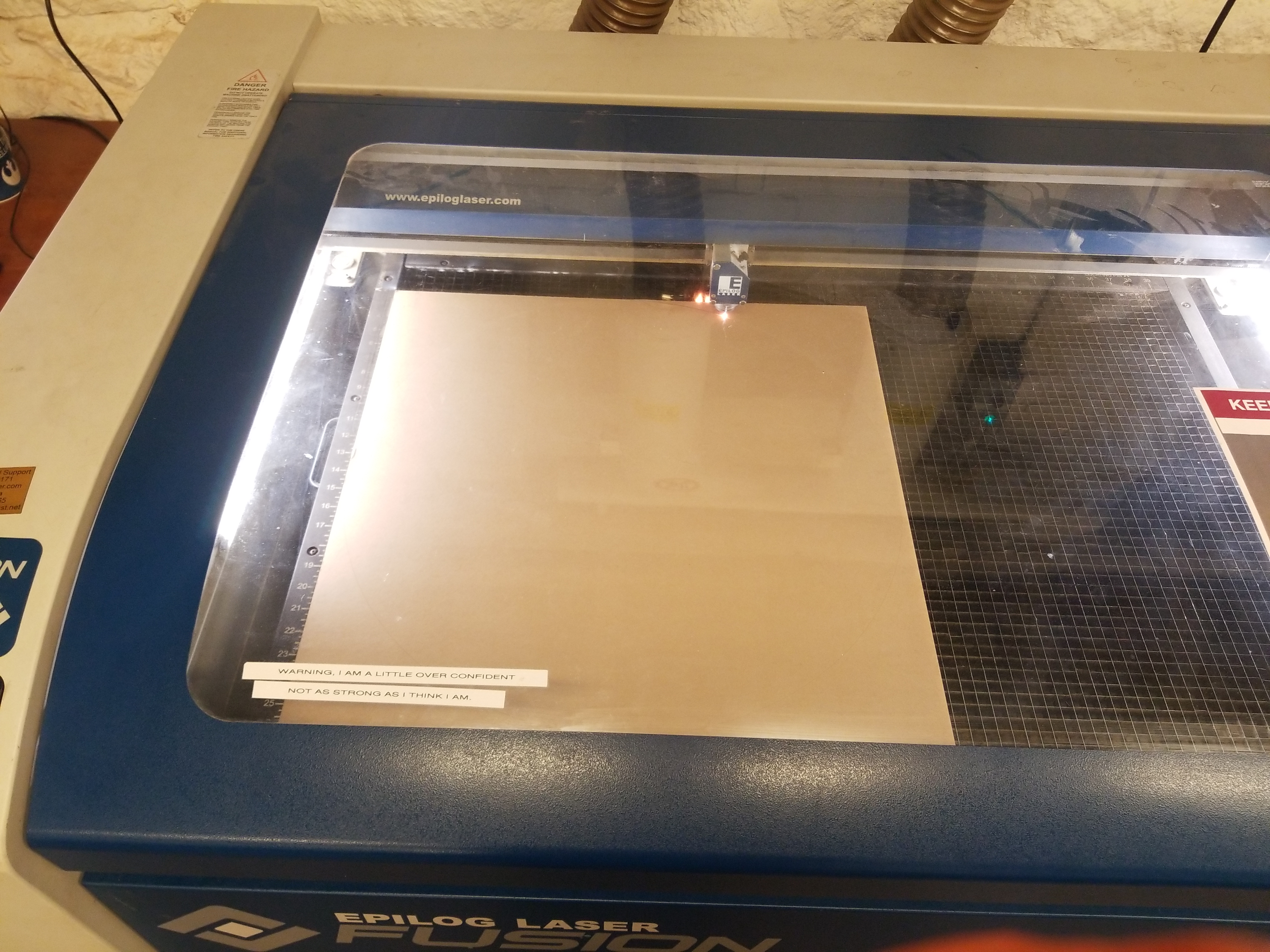 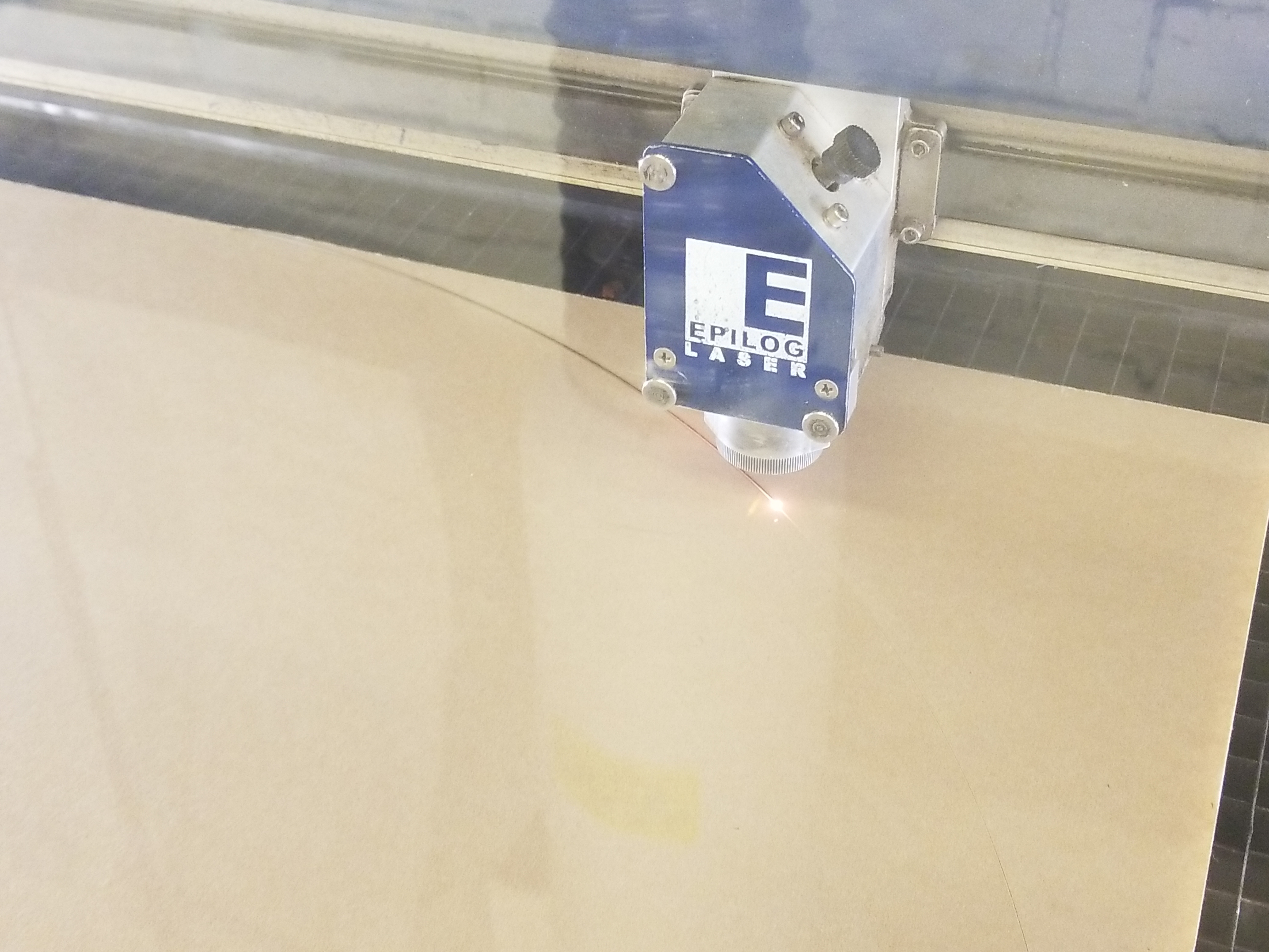 Large
Acrylic Round Large
Acrylic RoundWhile at the ever-excellent hobbyshop, I cut out a 23.5" circle from a sheet of 1/4" 24" square acrylic stock. This time I was smart and also made a small center hole for alignment of the magnetic coupler. |
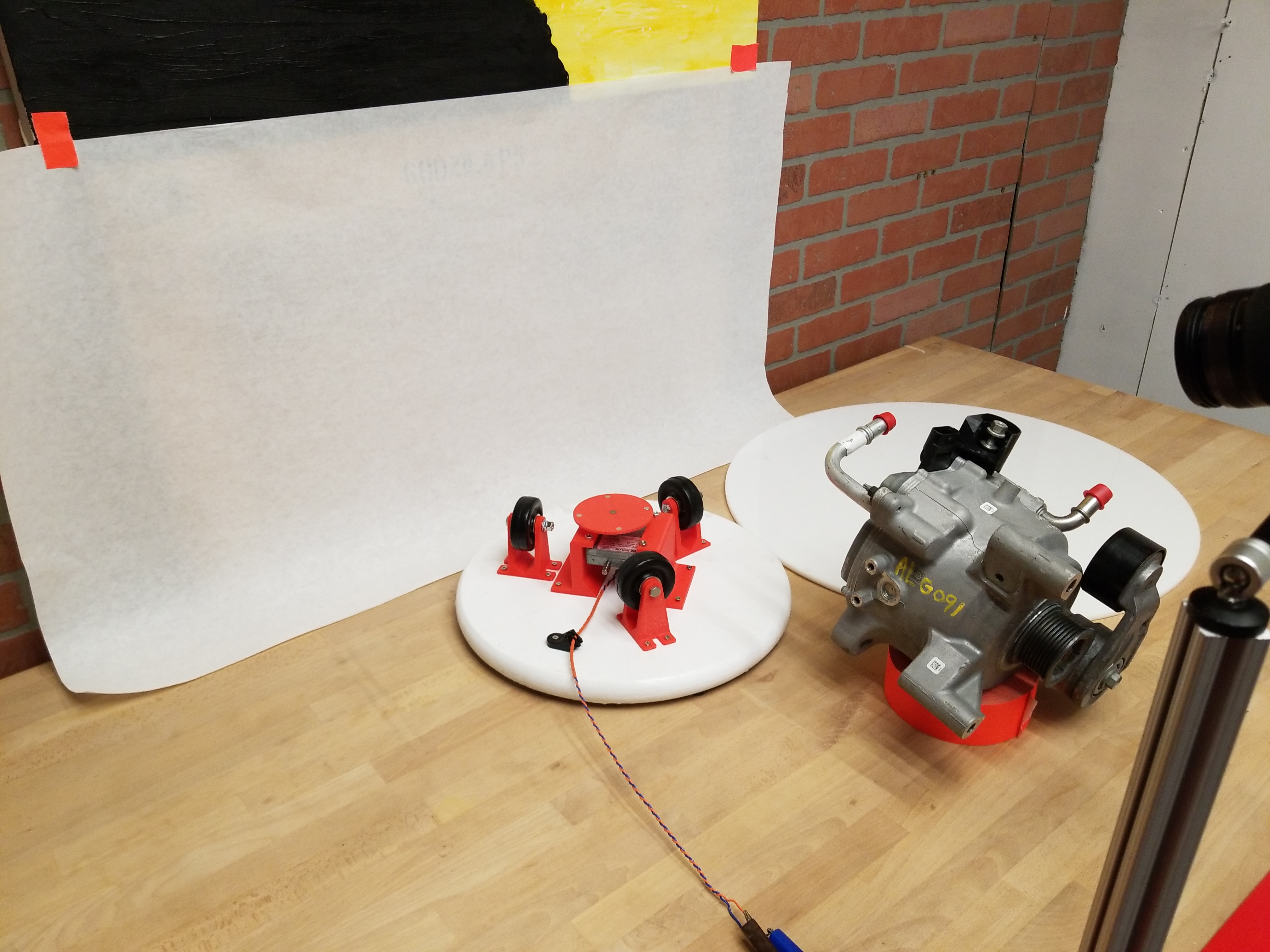
  With
the two options cut and glued we have the basic setup With
the two options cut and glued we have the basic setupI added a piece of masking tape on top of the magnet assembly, mostly so the surface was easier to clean metal particulate off of. Being able to swap out rotary platforms is really nice. |
 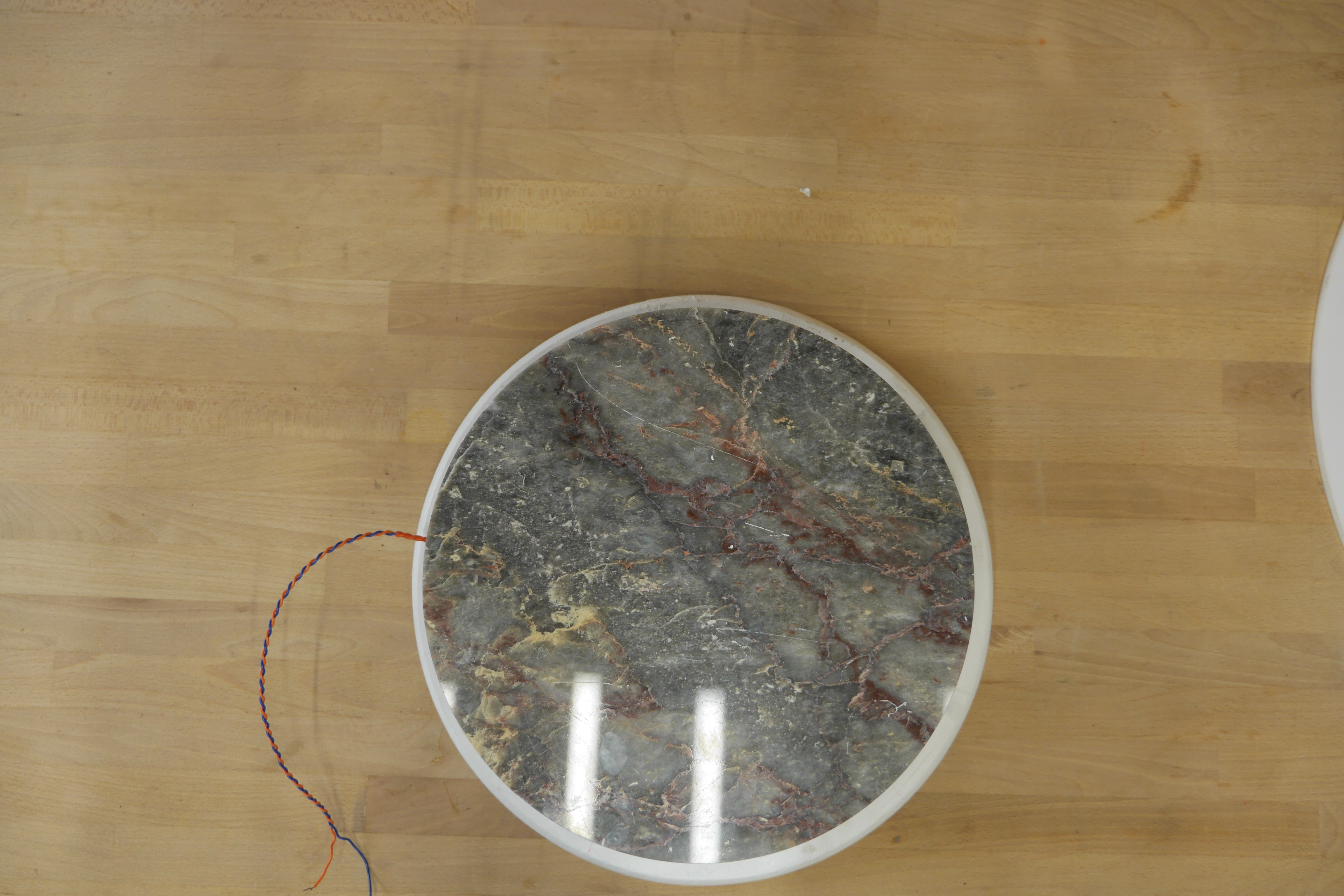 Top view of rotary
platform mechanism Top view of rotary
platform mechanismI was fairly surprised how well the centering worked out for the location of the motor shaft. The granite rotary surface is smaller than the base, by approximately 1" in diameter, |
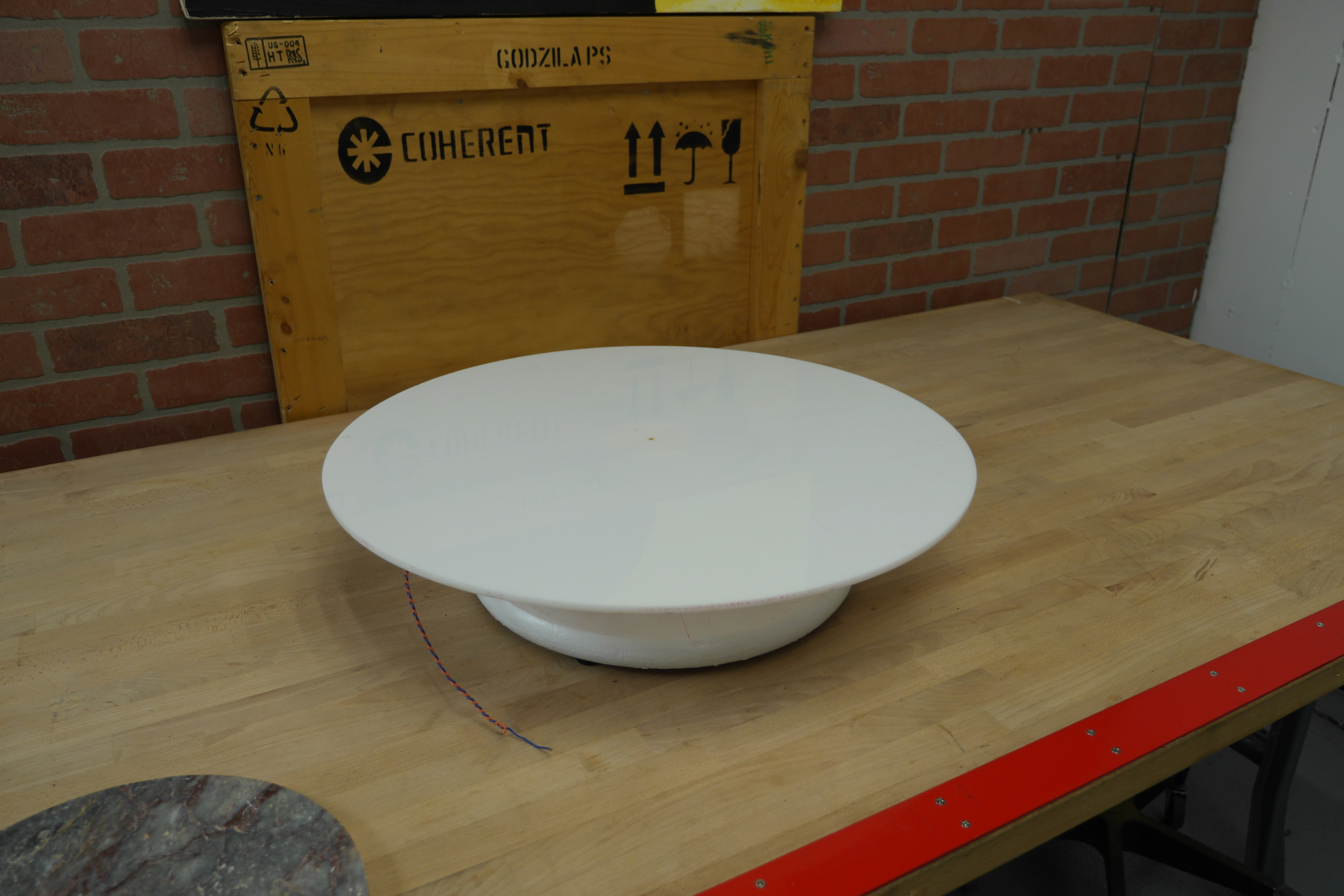 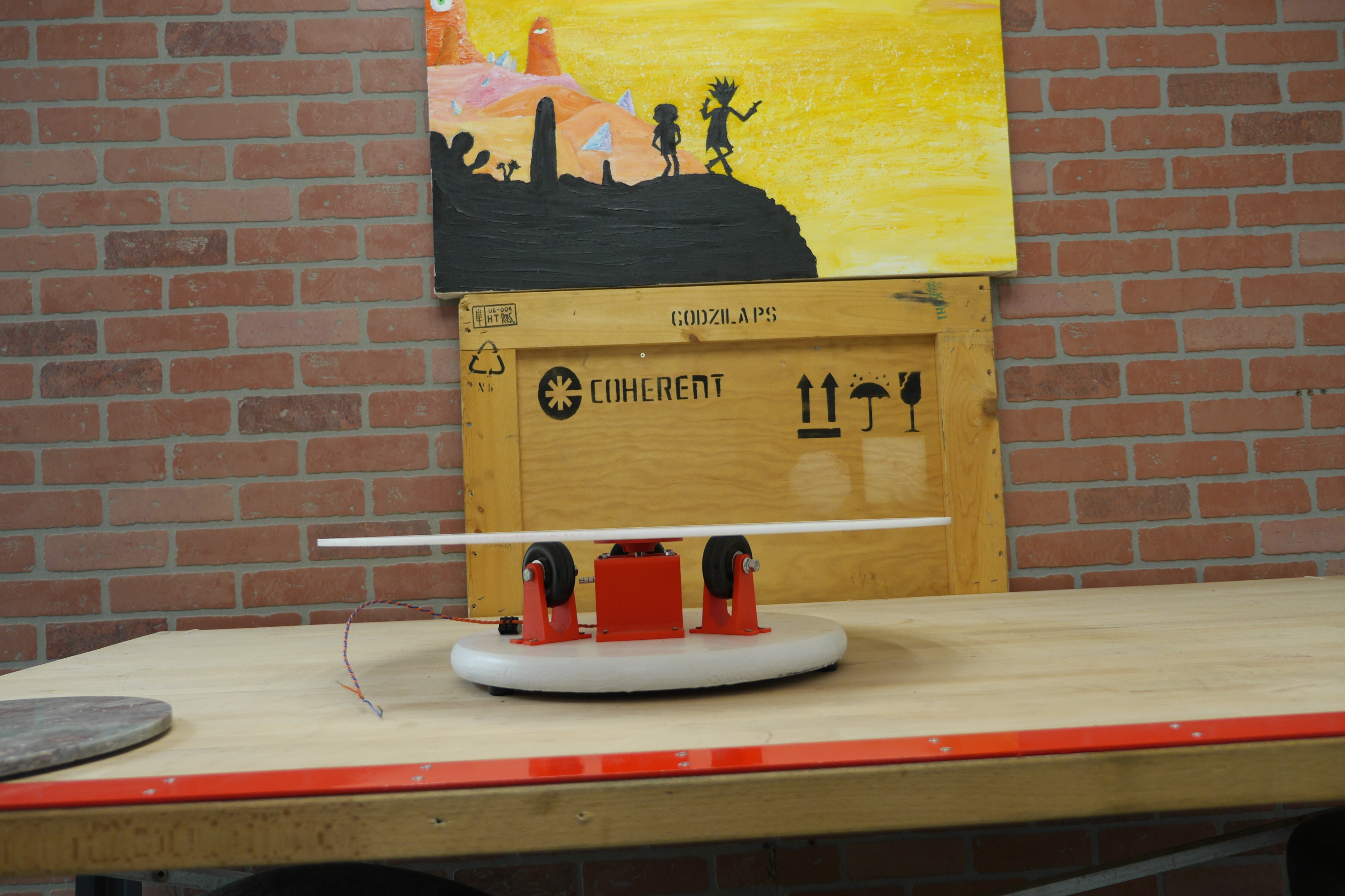 The white rotary table
surface is fairly gigantic, which works well for taking
photos of larger items The white rotary table
surface is fairly gigantic, which works well for taking
photos of larger items |
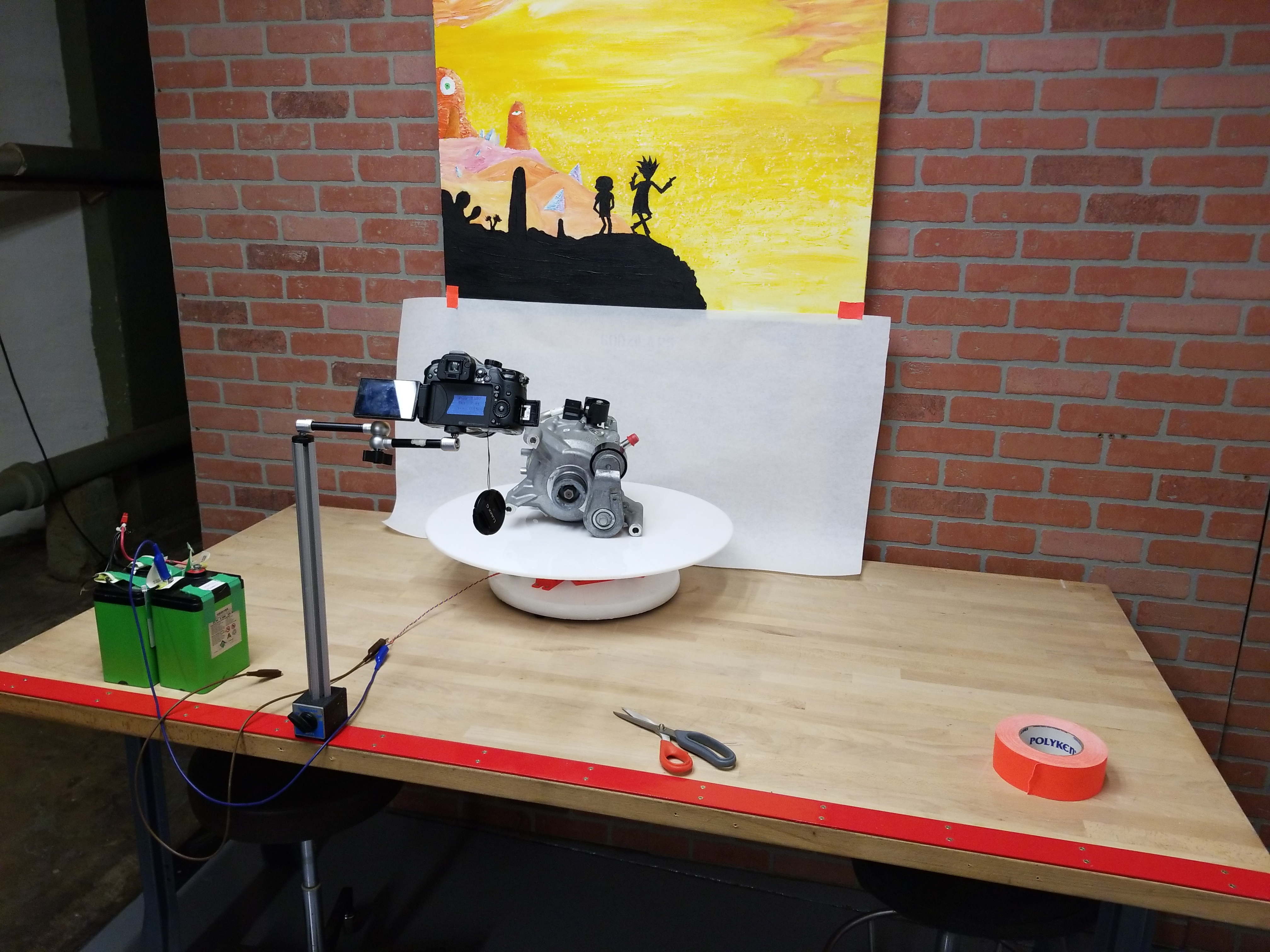  One of the first things i
took photos of was a 48v hybrid motor, which was rather
large. Even without a time-lapse controller (running
directly from a 12v battery) the shot was great. One of the first things i
took photos of was a 48v hybrid motor, which was rather
large. Even without a time-lapse controller (running
directly from a 12v battery) the shot was great. |
| S |
(There's
other photos in the photo
gallery)
Concluding Remarks:- This is one of those projects where making the mechanical
bits was quick, and because it could run off a DC motor, i
could just run it on a power-supply and that was fine. It took
me a bit to get around to making a position controller and the
works.
If you have questions or comments, ask below or send over an email.
| Comments: |
|
HTML Comment Box
is loading comments...
|
Dane.Kouttron
Rensselaer Polytechnic
Institute
Electrical & Electrical
Power
631.978.1650
