
Dane Kouttron
Project Documentation: 02/2015 Reformatted: 01/2024
Combat Robot: Fission-Product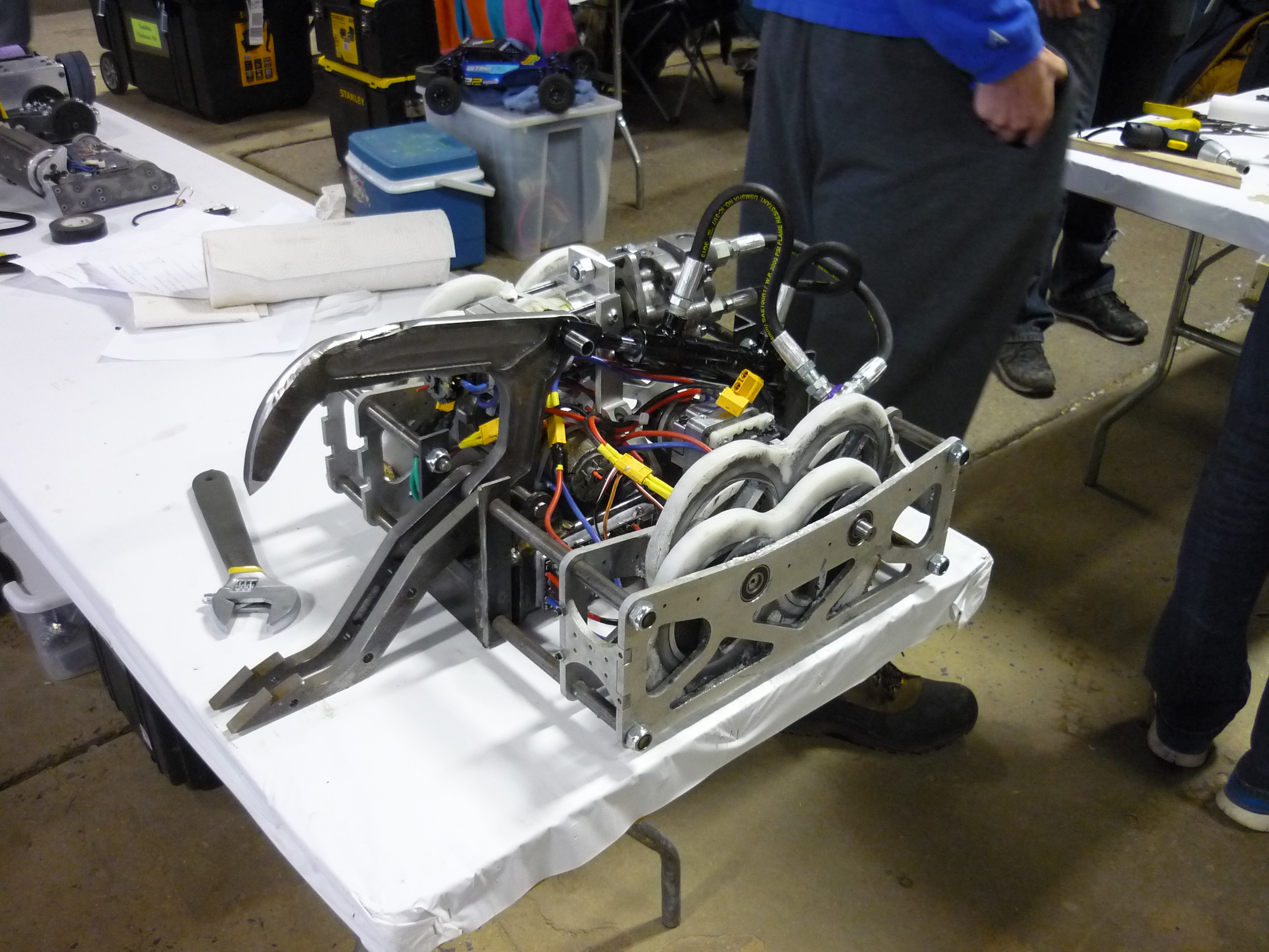
Hydraulic chomping shufflebot in a 30lb weight class you say? Impossible! Incredulous! The following details the birth of fission product, a 2015 motorama sportsman entry by myself and the ever-awesome Adam Bercu. Fission Product was designed and fabricated during the boston bilzzard-weeks and brought to life with the help of miters comrades and a lot of on-the-fly machining. |
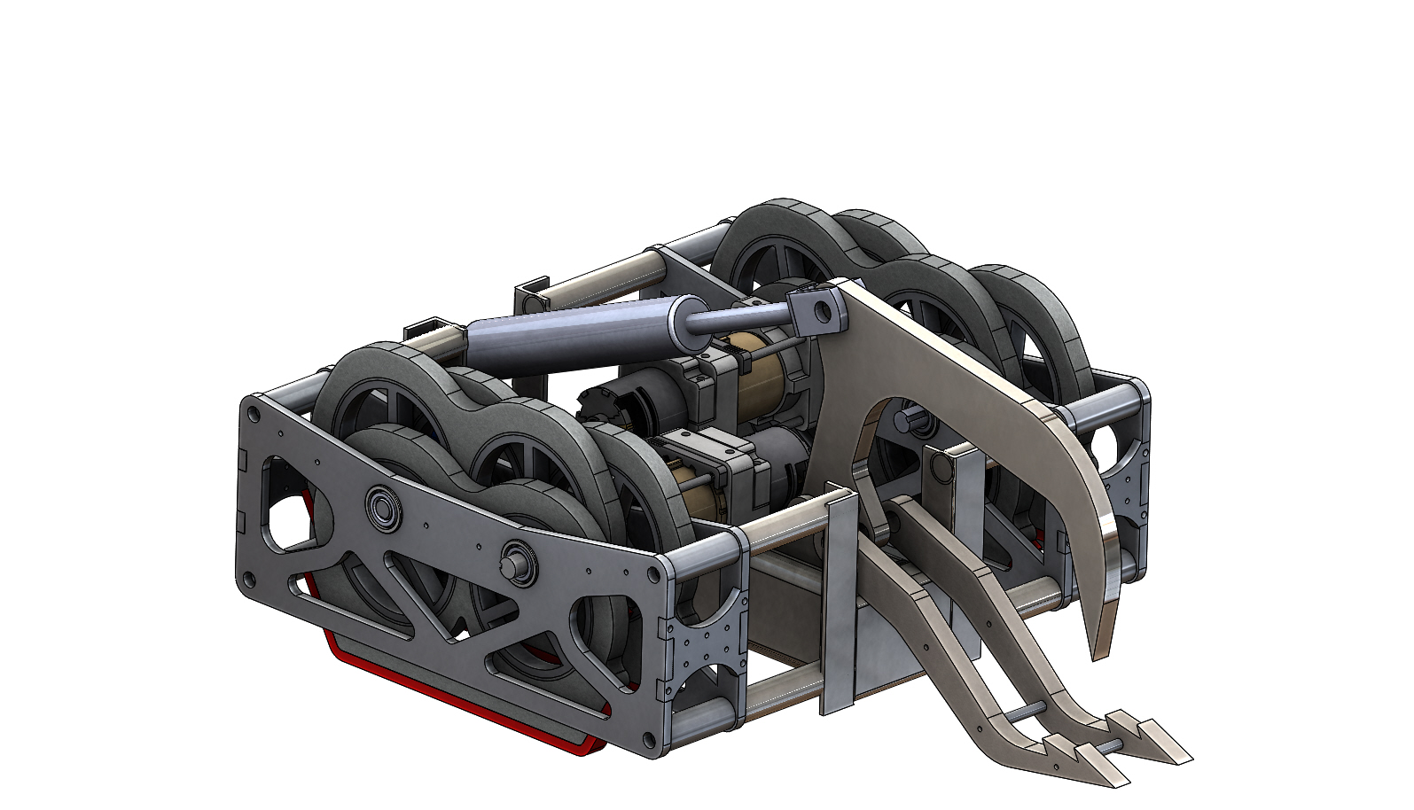
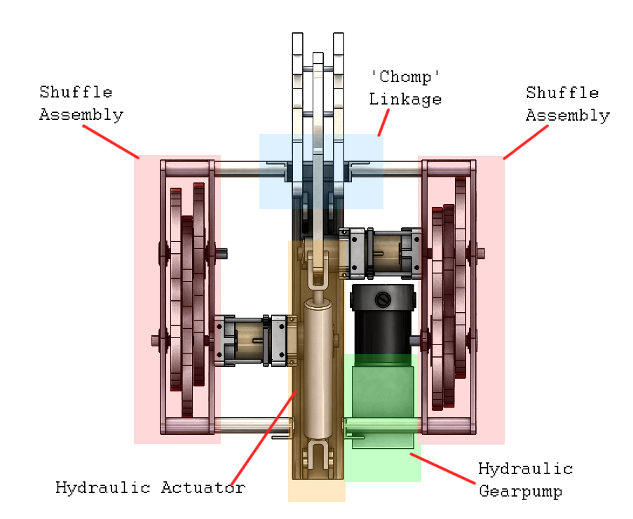
Optimize for Pinch PointsFission product was born as an iterative Solidworks design. Shown below is the robot in working CAD form, with both shuffles actuating and jaw chomping. Note the 'chomp' action is on a linkage, allowing combined lift-chomp from one actuator. The drive propulsion is based off of the equalszero DEWUT, motor assembly, highly reccomended. The following page documents design decisions, hardware fabrication, testing and modifications to the robot as well as feedback from its operation at the 2015 motorama combat robots event. If you're interested in shuffle propulsion, stay tuned. 
Whats in a name
Whats a fission product? Fission Products are the fragments left over from fission reactions, some short lived 'out there' elements that rapidly decay and a distributuon of more common longer half-life elements. This robot is a strange one, with a fast moving shuffling drivetrain and non traditional hydraulics in a 30 lb weight class.

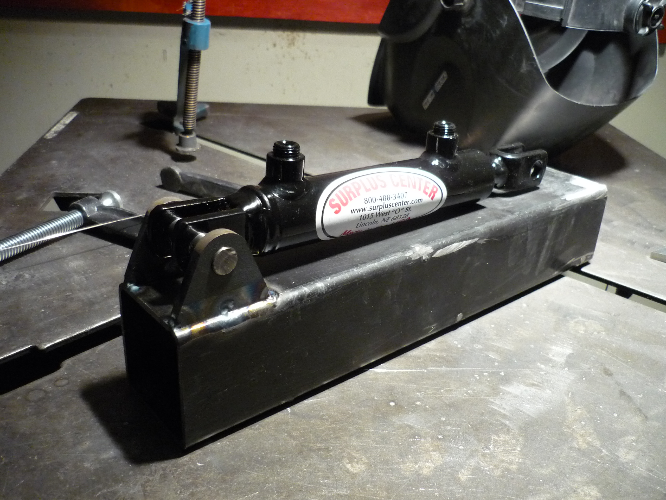
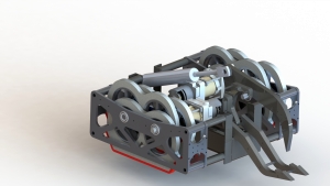
Everchanging CADCAD: Brought to you by snow-days and mount AlbanyThe robot design phase occured during the 2015 snow-blizzard apocylapse. Roads were blocked, MIT was closed, trains were stuck, but Solidworks and team bercu-tron powered on through some cold evenings. Rendering of the complete bot is shown below. The heart of the bot was a surpluscenter hydraulic gearpump and piston. 
A note about dual-wielding CAD. This has been a recurring theme in recent projects; its fairly cumbersome to 'parallel' work on a CAD model, so there's a lot of meetup and CAD-jam sessions. Fortunatley, this does bring about a bunch of interesting ideas as to how to design around issues, and optimize loading. These sessions generally ran into the late evenings, resulting in the next-day's meetup to start with 'what the heck were we thinking at 3am', and a bit of iterative re-design. 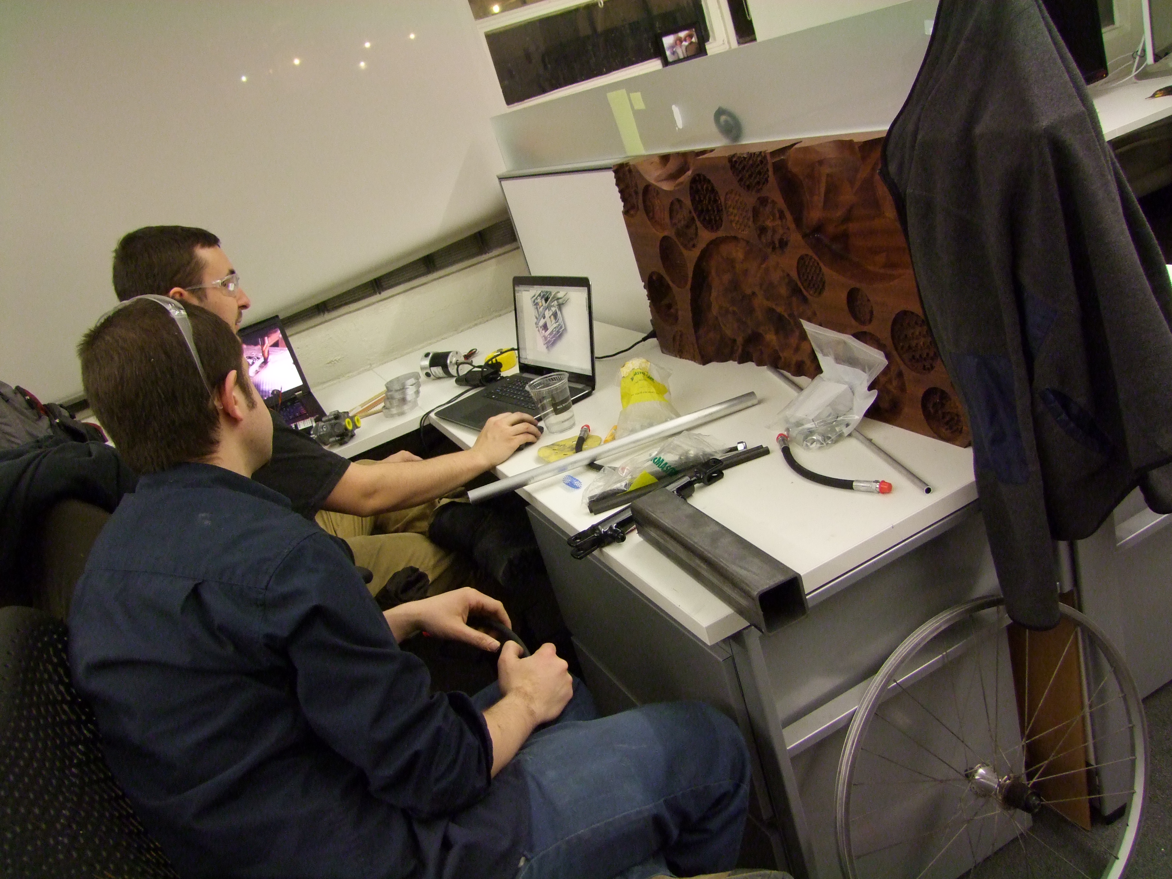
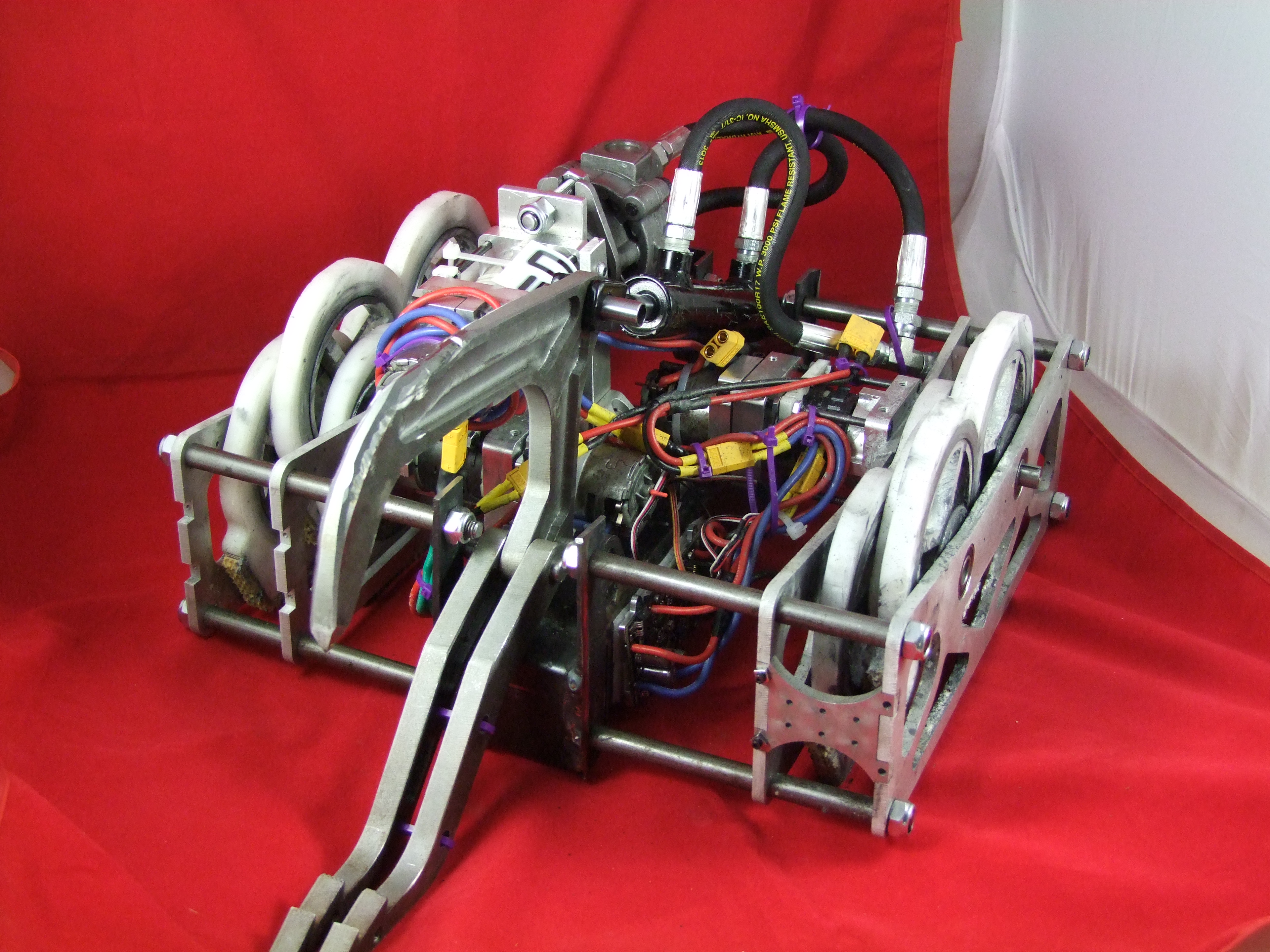
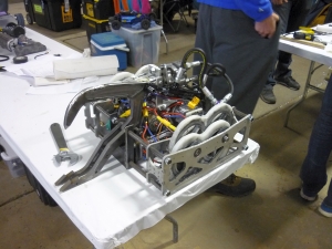
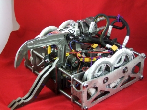
Overview. A top view shot of the robot shows the intended hardware placement. Note that the hydraulic gearpump was modeled as a box, as it was fairly slow to arrive from surpluscenter. The shuffle assemblies are rotated mirrors of eachother, as this allowed the robot to have a smaller width-wise footprint. 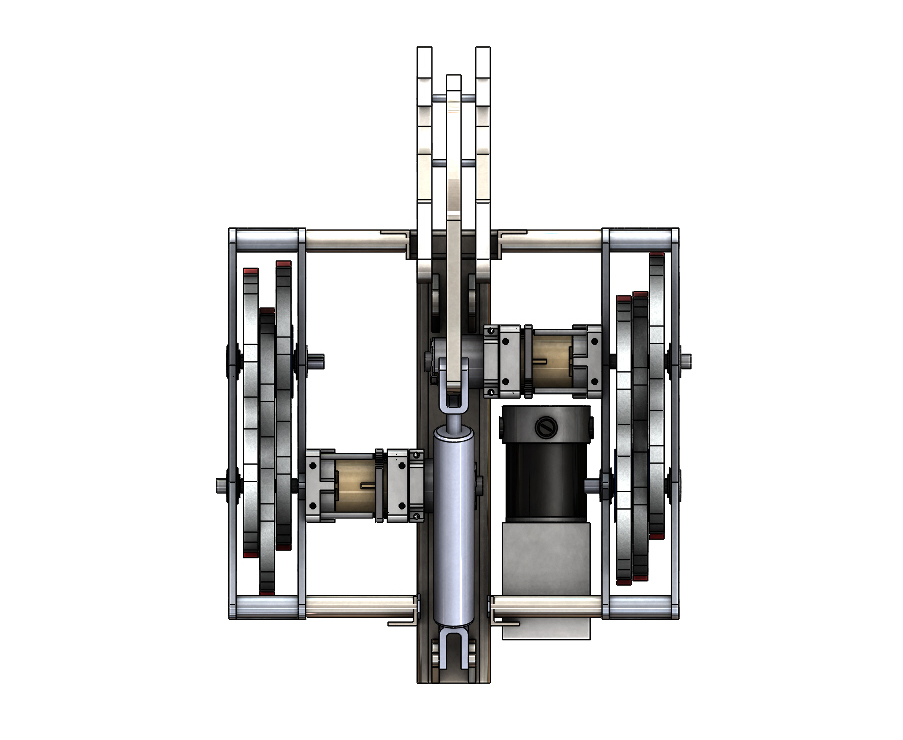
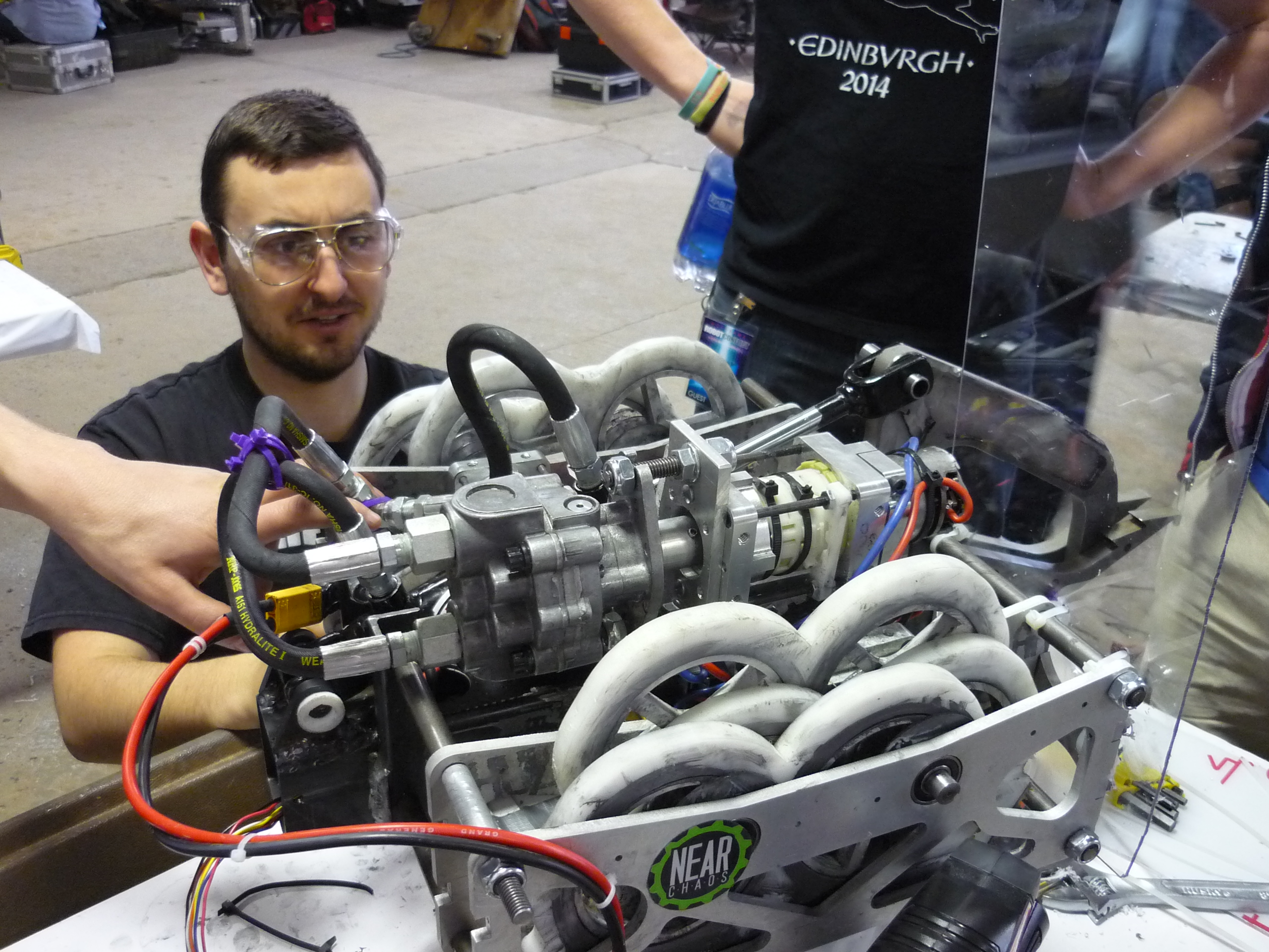
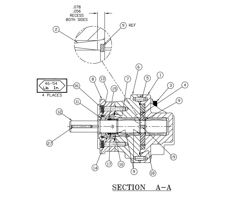
Hydraulic Hardware and Hydraulic loop. The pump in question is a parker gear motor pump, available at surpluscenter [link], information about the pump can be found in the parker manual [link]. Interestingly this pump is bi-directional, unlike most equivalent gear pumps, and has a power transfer of ~10hp in a relativley small amount of space. There's even a nifty drawing of the part now [link] 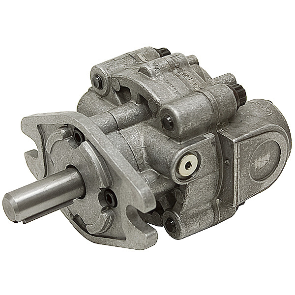
Shuffle feet and shuffle assemblies. The shuffle assemblies consist of 3 major parts, a CAM, a shuffle housing and the traction material. The design avoided bearings by using a slippery material for the shuffle itself. The delrin plastic is low friction but relativley strong, creating a bearing surface on the machined CAMs. Each cam rotates inside the shuffle. The traction material mates with screws in tapped holes. The traction material (red) has an internal fiber layer as well as a high surface area traction material. The mounting screws deform the traction material and connect the fiber reinforced layer. 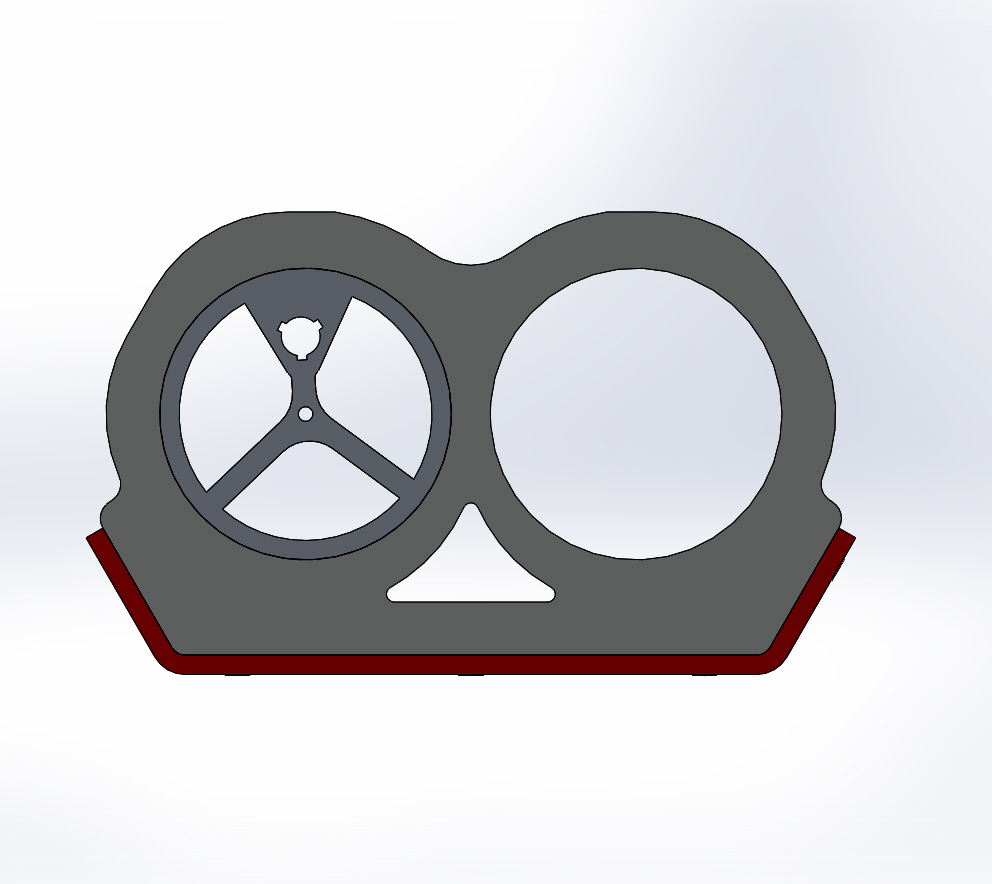
Electronics and battery assembly. The heart of the electronics for this build were two ragebridges, one for propulsion and the other operating in a dual-mode for current feed into the weapon actuator. 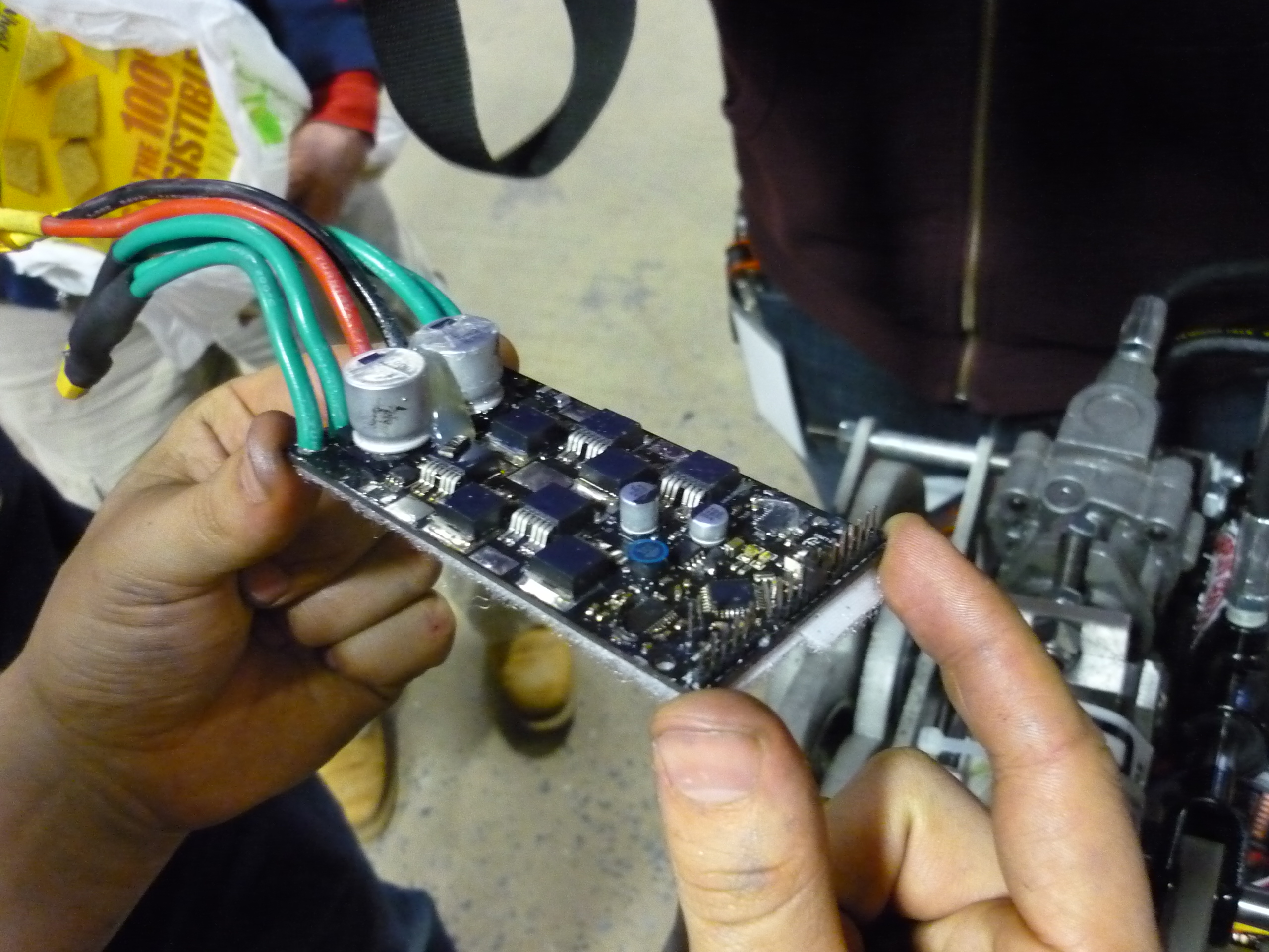
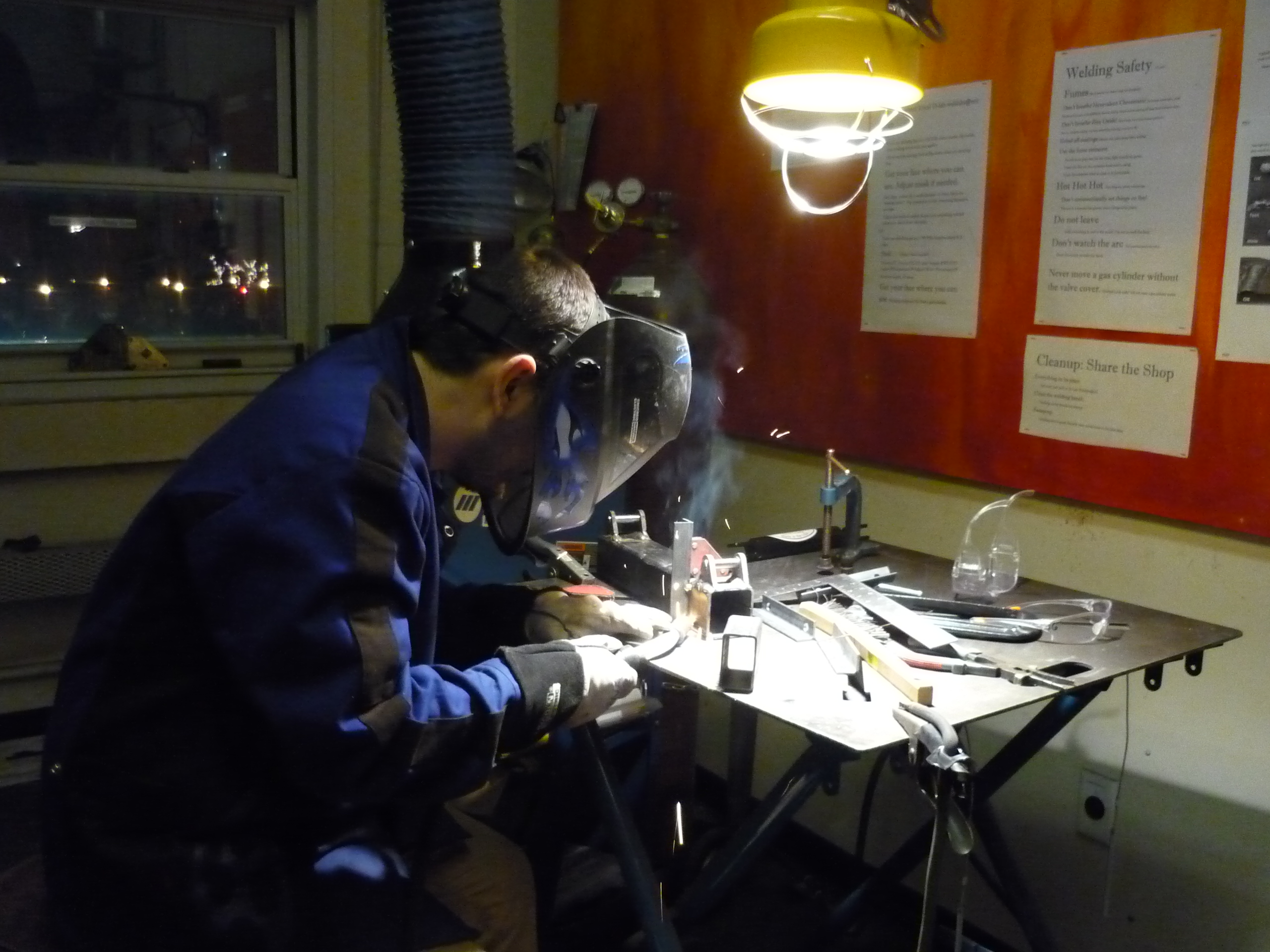
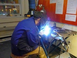
Frame Welding & WaterjettingThe frame was born from a thick rectangular steel tube. All the crushing force from the hydraulic actuator. Bercu welded on the back pin mounts. Note that all the actuator force translates though that pin. 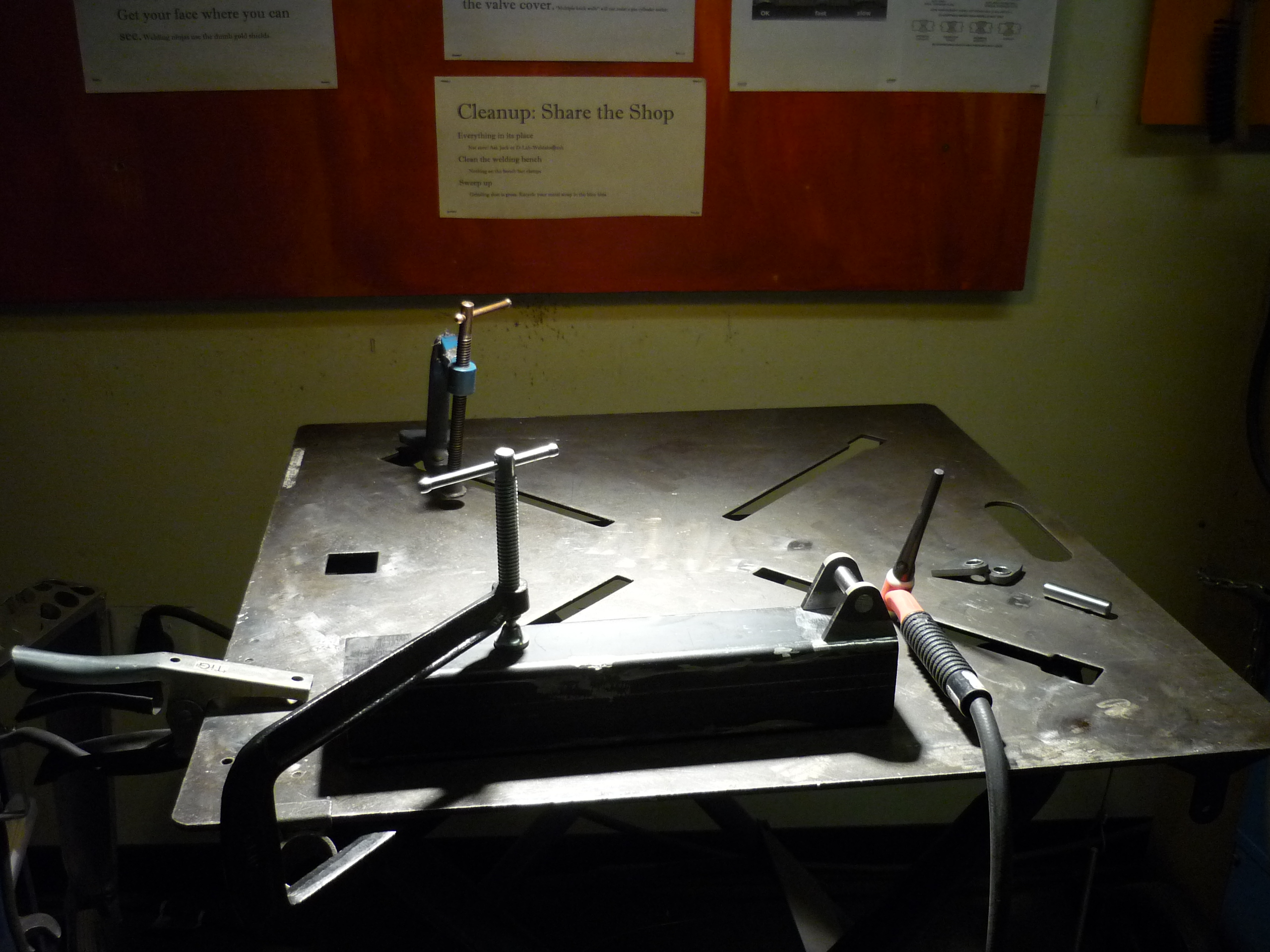

A similar pin mount is added to the front of the tube. This houses the main pivot for the claw. Pin was left installed to keep the two parts colinear while welding. Note that spatter from the mig welder did need to be removed from the pins to remove them from their mounts. Covering the pin, with a leather work glove or metal scrap would prevent splatter. 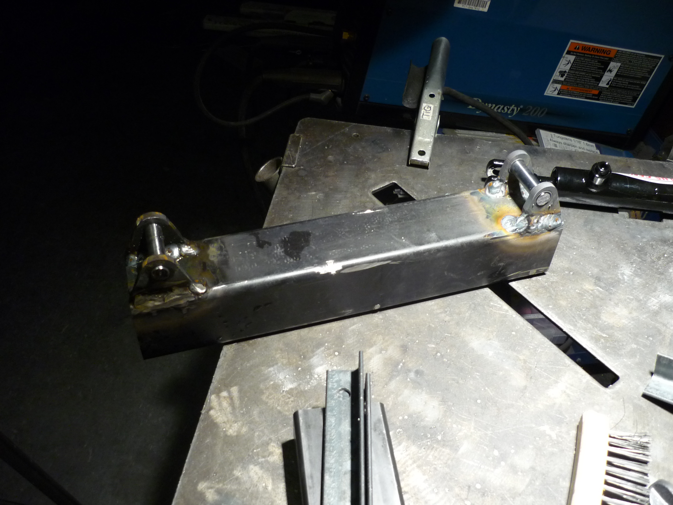
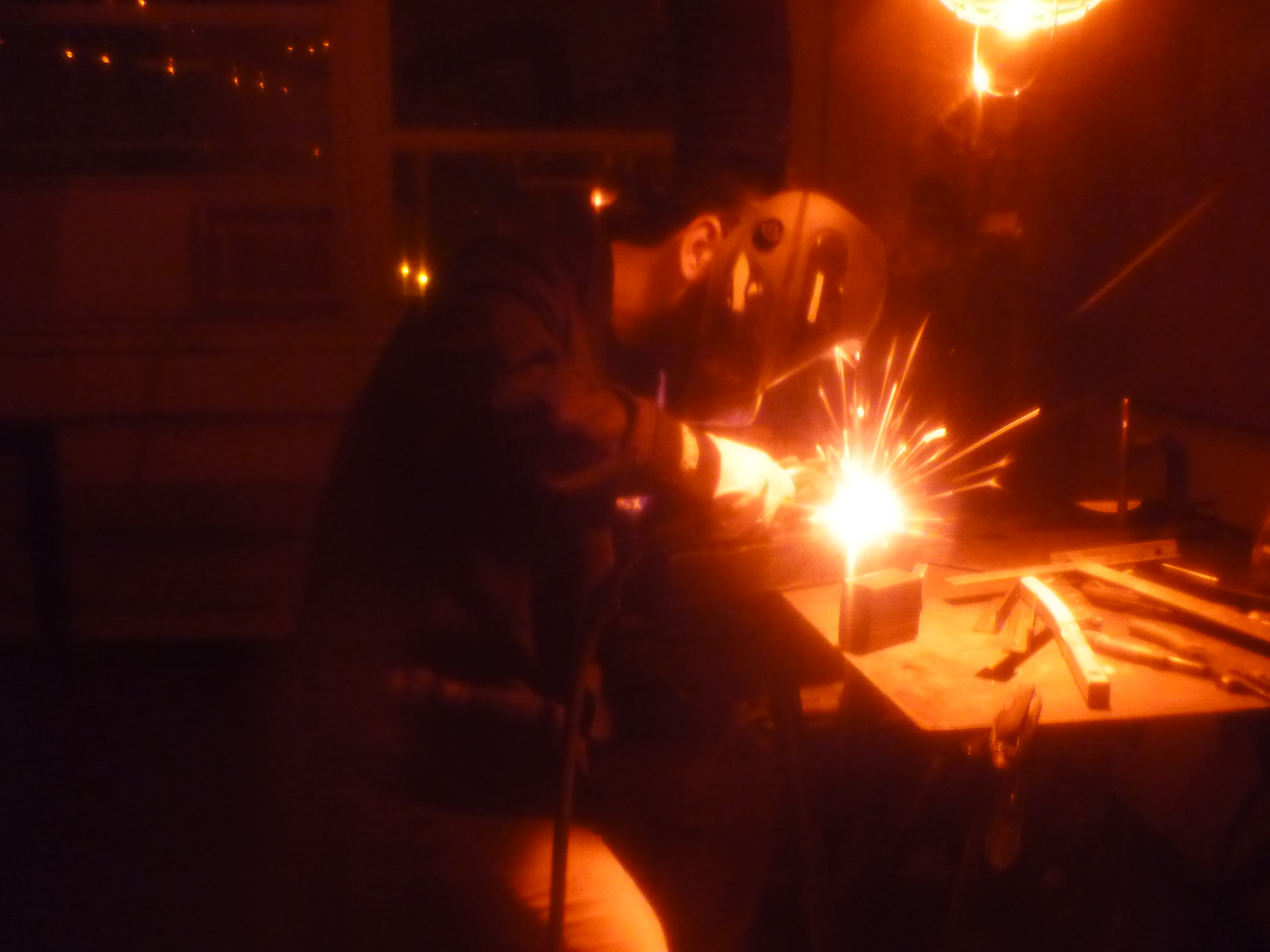
A Bercu welds and welds and welds, and the frame starts coming together. 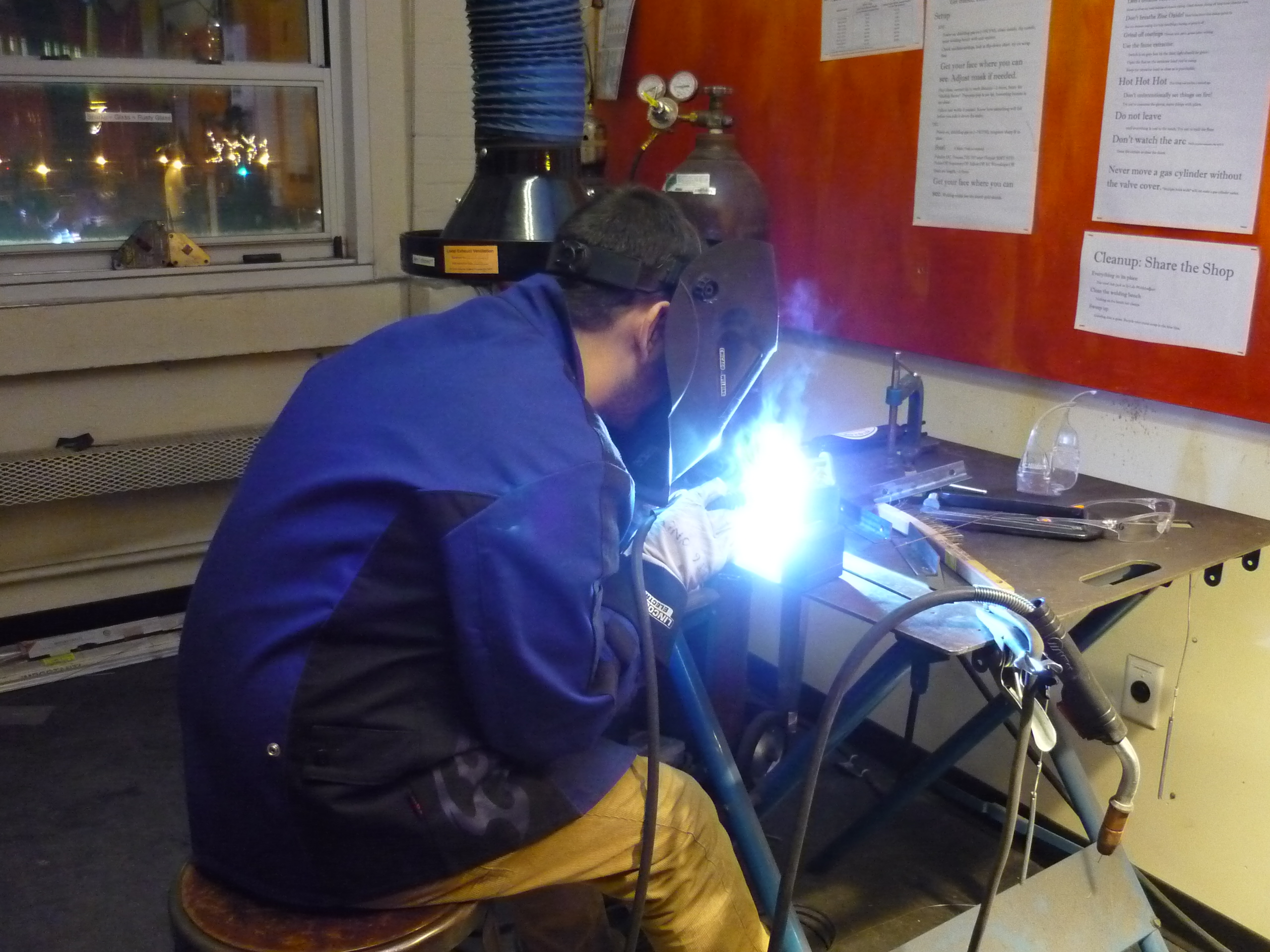
TOOL STEEL JAWS. Hydraulics can pummel quite a bit of pressure, as such we chose tool steel for the chomping jaws & pincer. The steel plate was huge, shown is the CSAIL waterjet slicing through the thick plate. Abrasive waterjets make the task of identical jaw braces a cake-walk. 
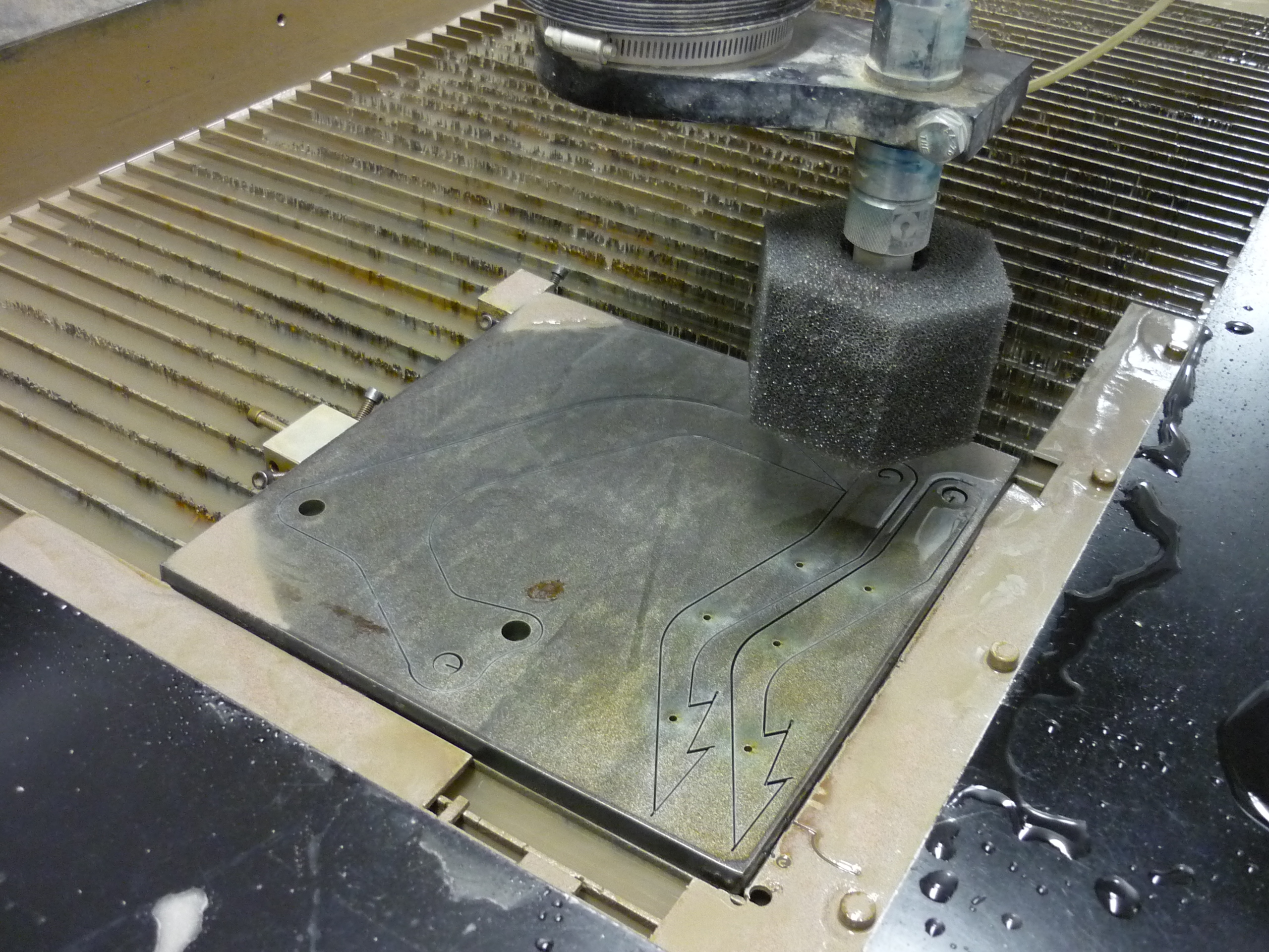
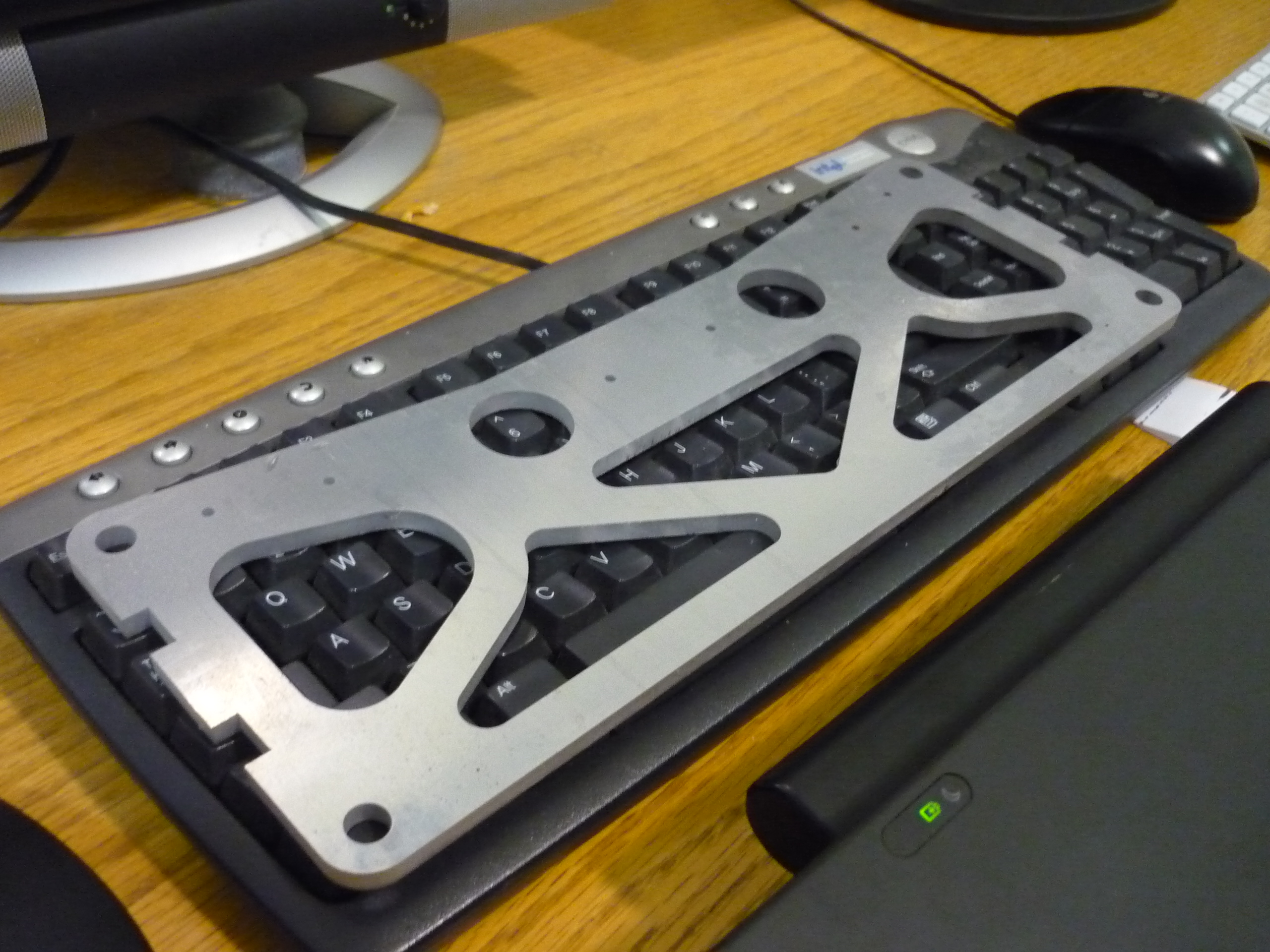
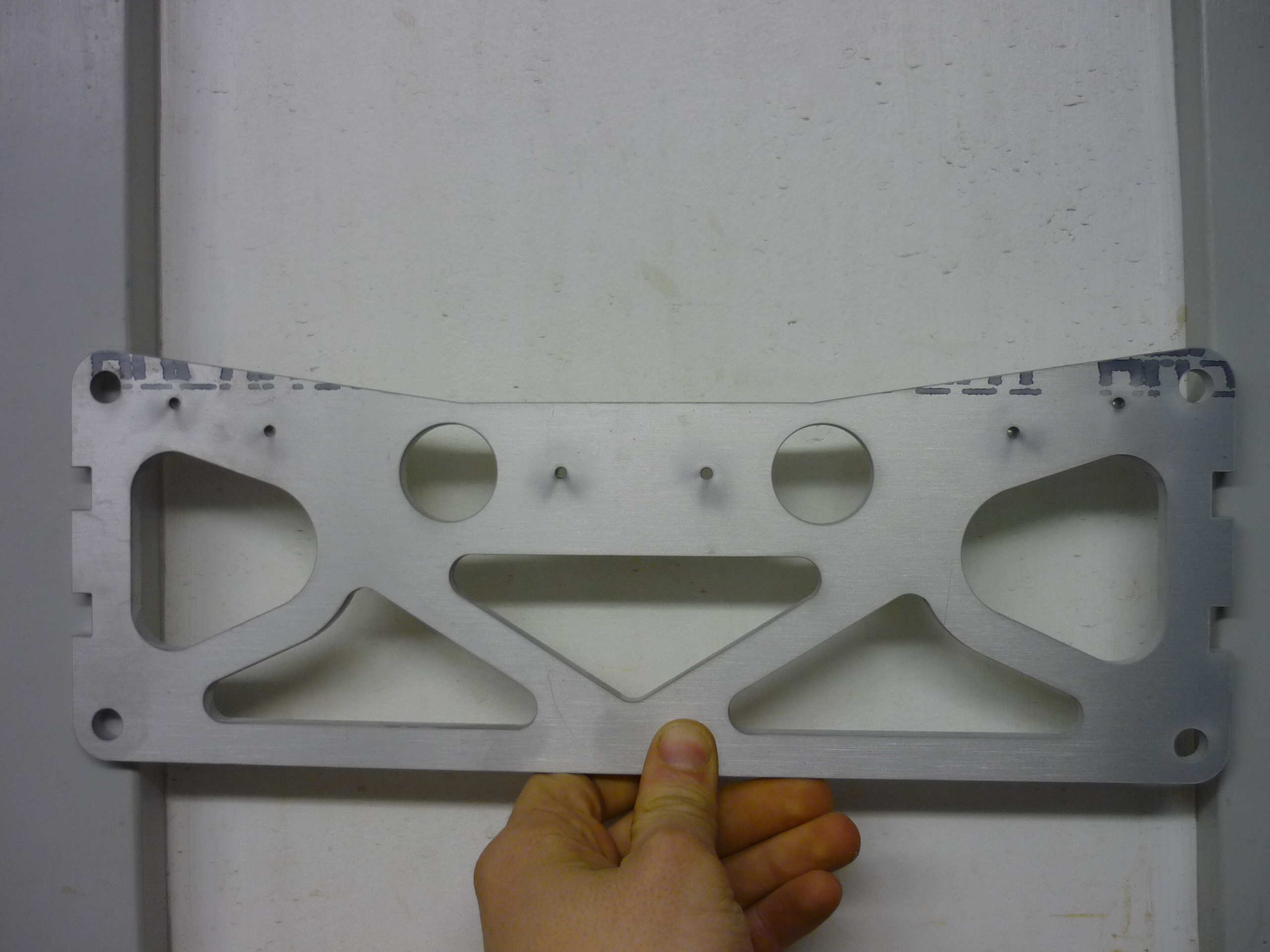
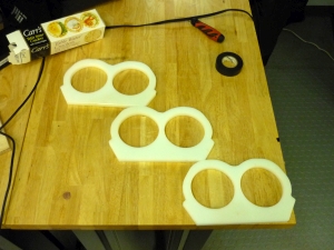
Shuffle mounts. The side plates for the shuffle holsters were also waterjet, this time out of 6061 aluminum. The design did contain purpose-built smiley face speed holes. Cutting these out was a bit of an eye opener, they cover the majority of a standard sized keyboard + numpad. This was one of the frist 'this is going to be a monster' realizations. At least its a smiling monster. 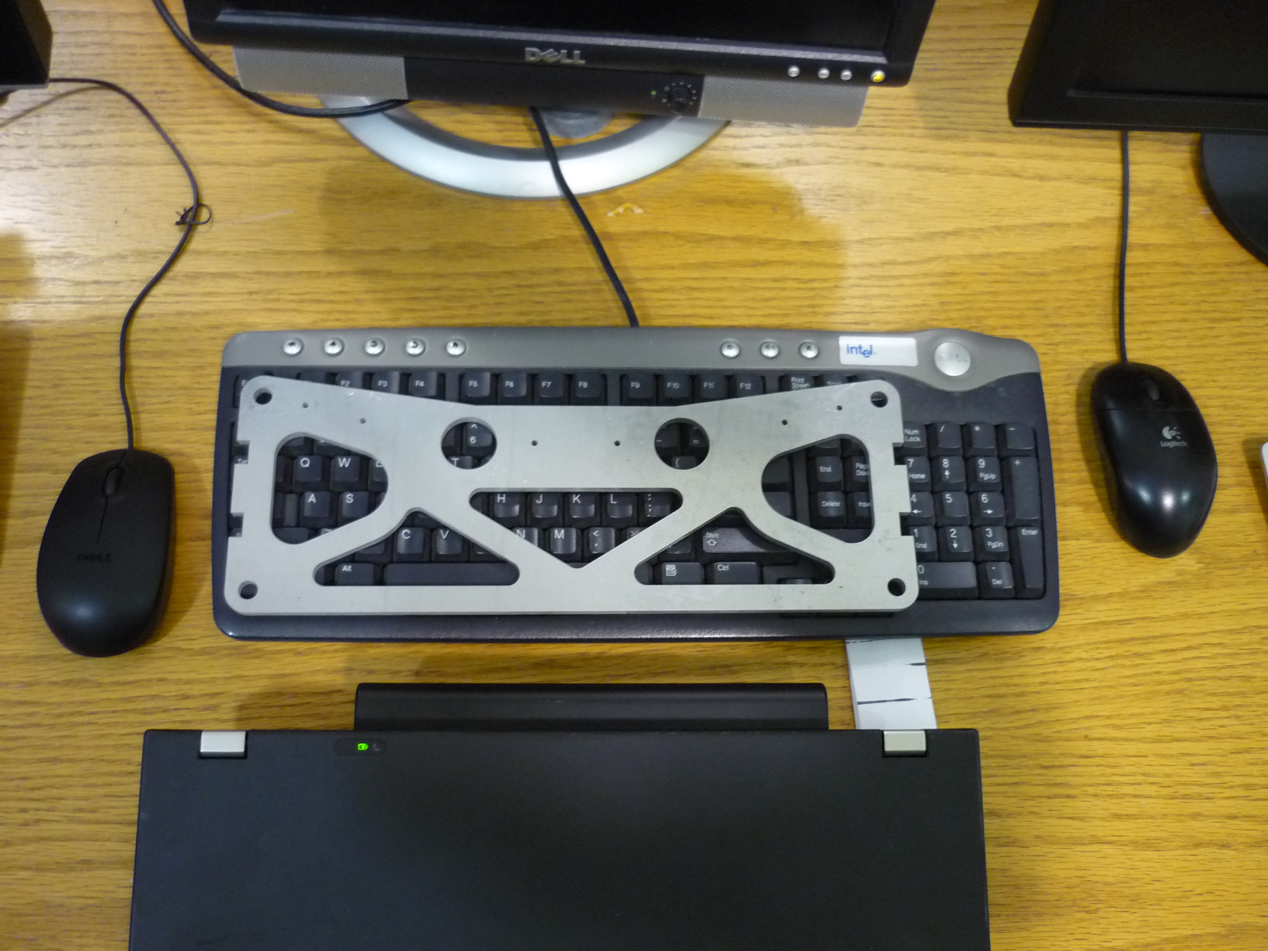
More Waterjetting. All that 1/4" plate turned very quickly into shuffle parts. Shown below, for scale is a 55 gallon drum full of waterjet sludge. 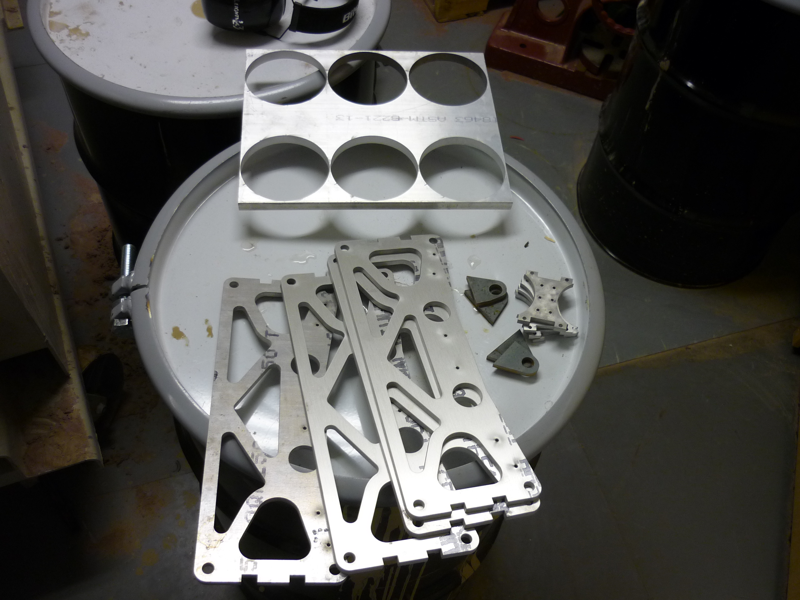
Machining the Shufflers and CAMsWith some crackers and nice oil, the plastic machining begins. The delrin sheet was cut into smaller chunks on the might BOLT herco, A dash of HSMworks and bercu-waves and we had path files for the machining. 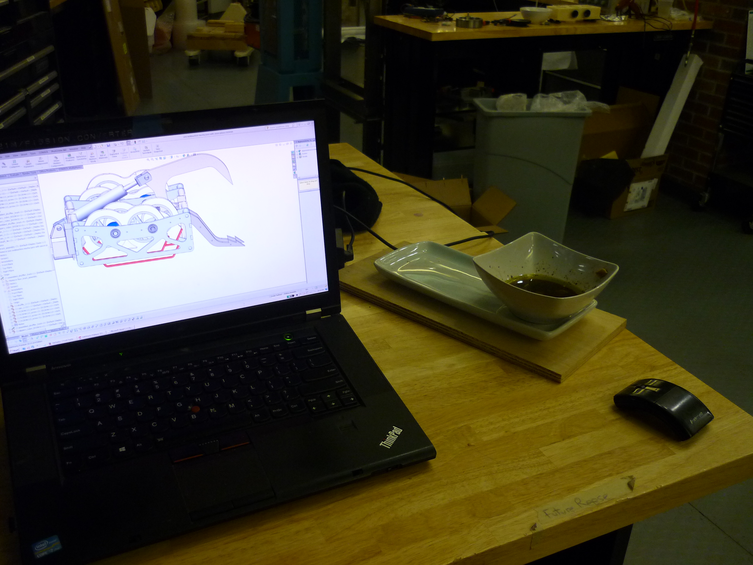
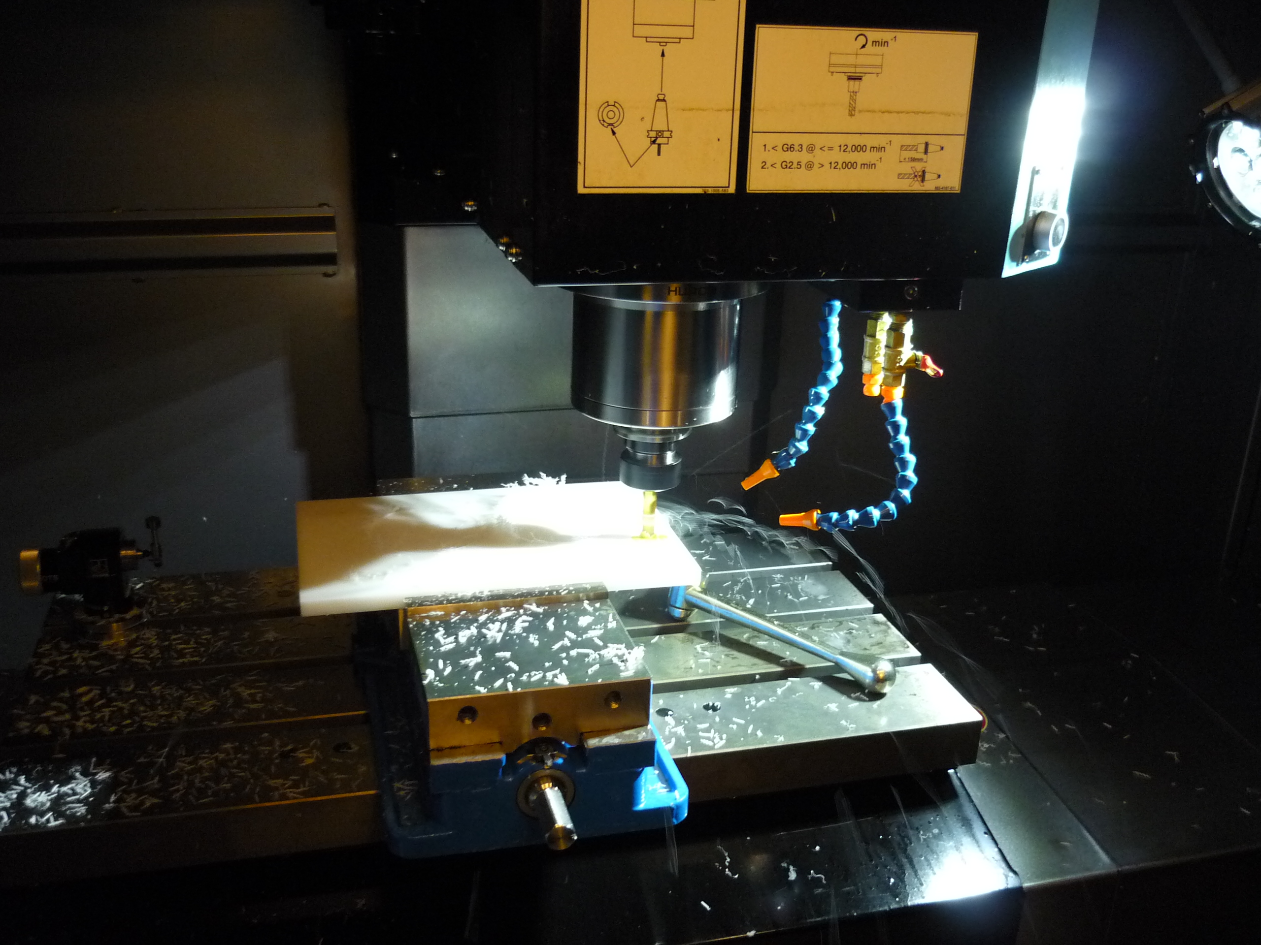
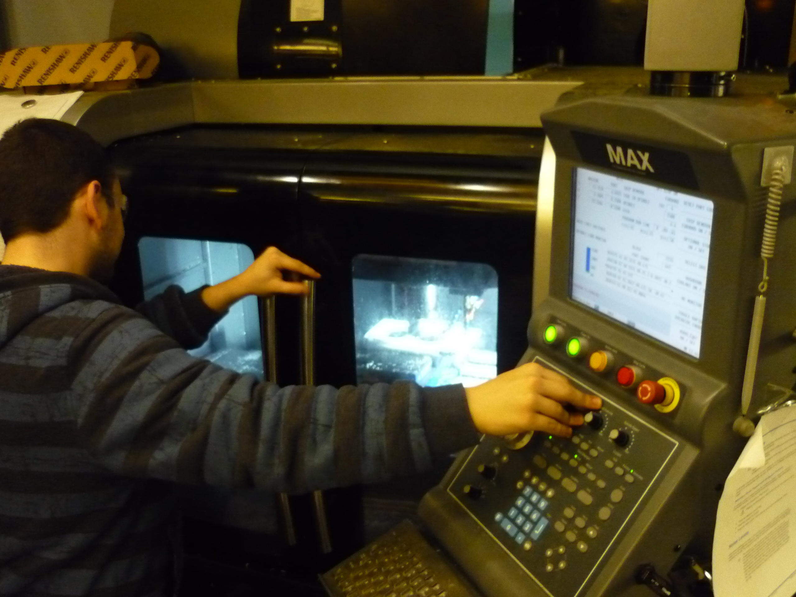
A quick pass on the CNC. A 1/2" endmill was used to cut a quick outline of the part. This was the first time we realized how huge this contraption was. We checked that everything wasnt in the wrong unit system, and calipered. It's a beast! 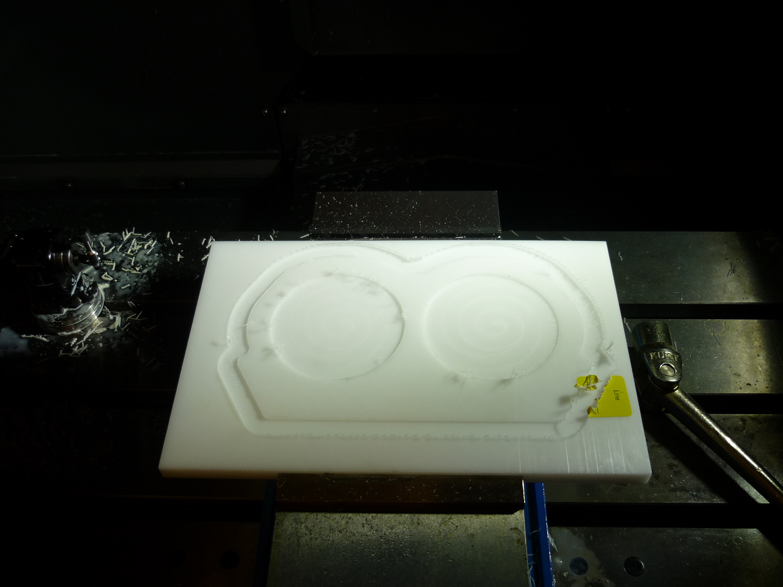
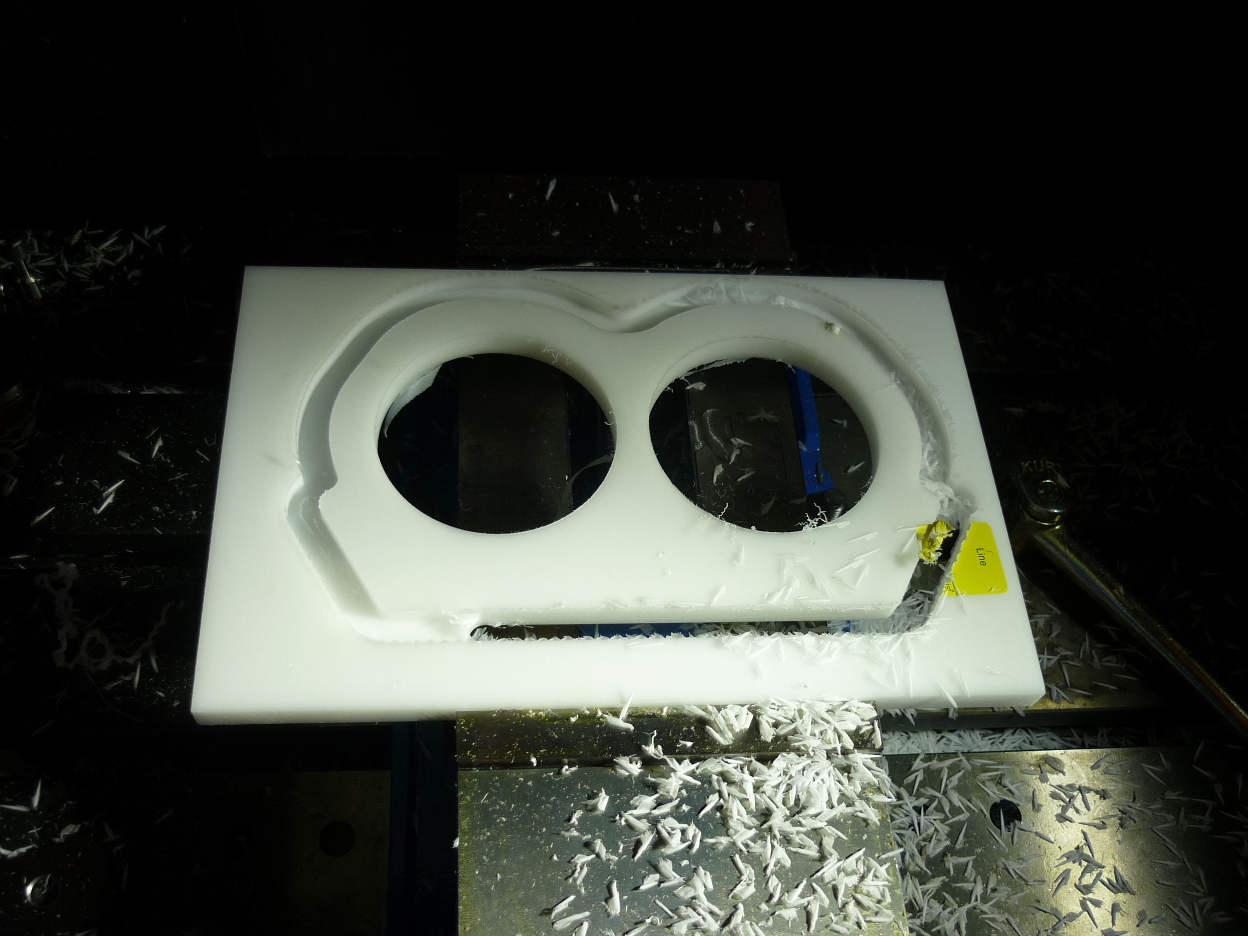
Bandsaw and Sanding. Cutting the whole part out would result in it jumping around with a highspeed endmill neary, so instead we cut out as much as possible and secondary-machined the last bits via bandsaw and beltsander. 
Post machining: Before & After. Shown is the post machined shuffles and the quickly consumed crackers. Tiny bandsaw worked wonders! 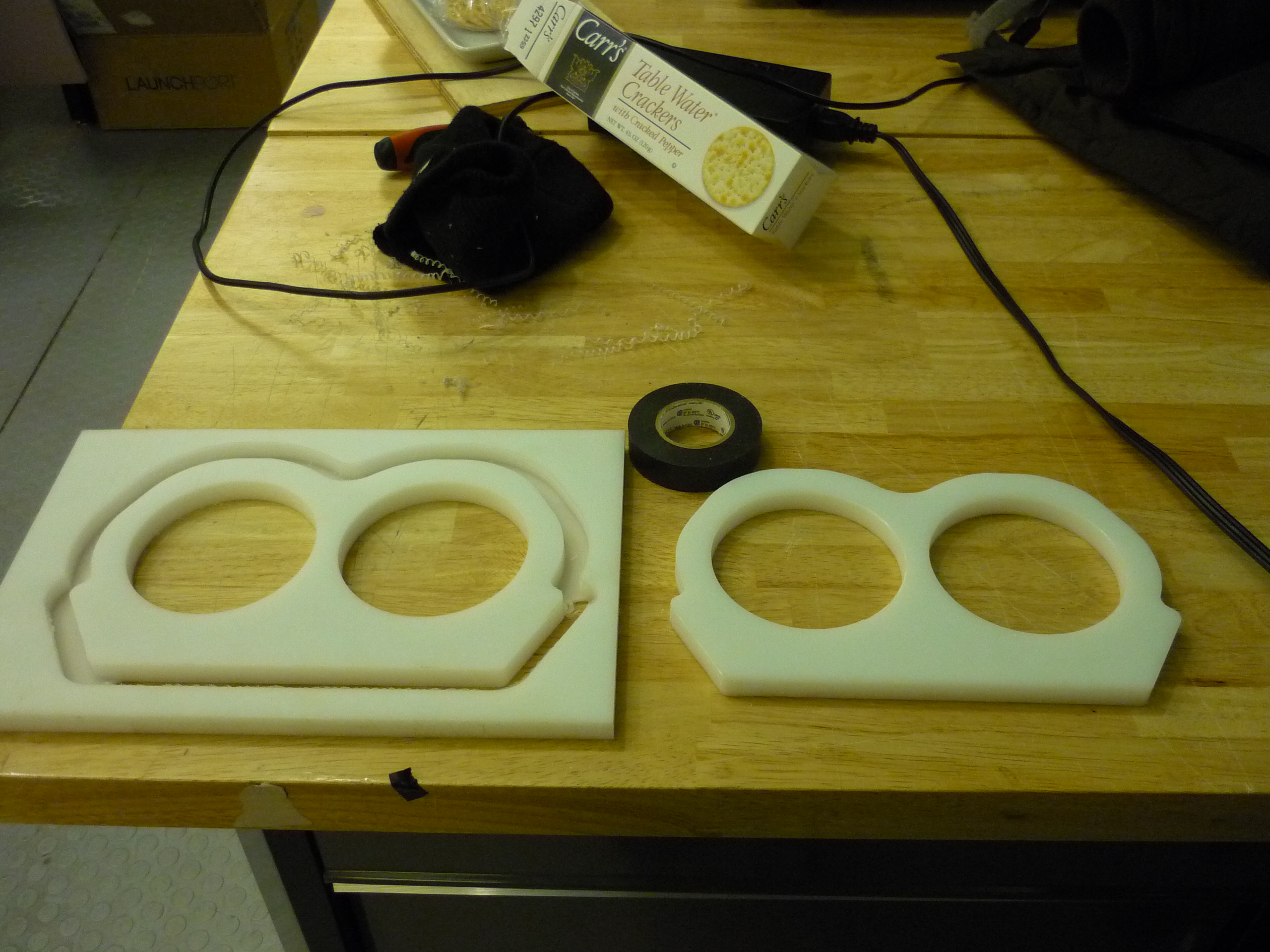

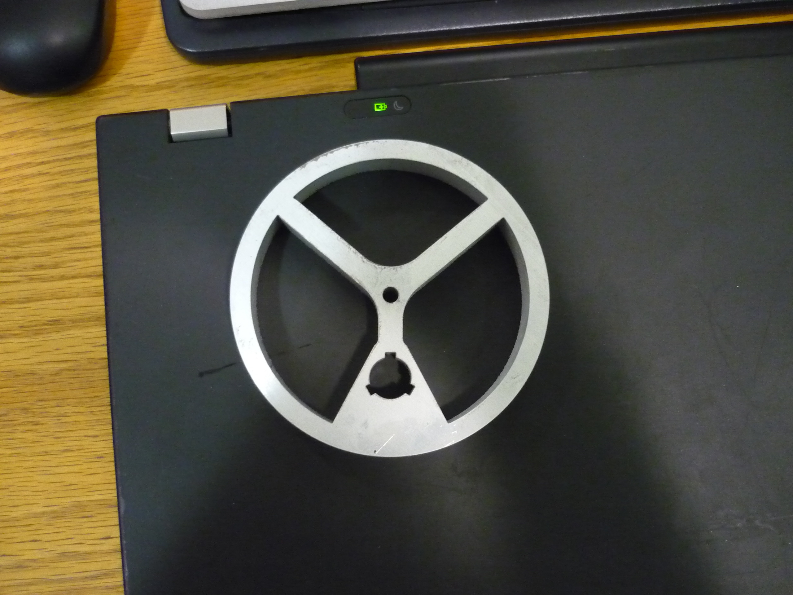
The cam's are a cute design. Note the 3 slots for keyways, this allows the cams to be offset by 120 degrees without needing special cams for each side. Why the 3 open sides? it allows you to reverse-jaw clamp the part on a lathe, which is incredibly useful for turning down the outside surface to a machined finish. 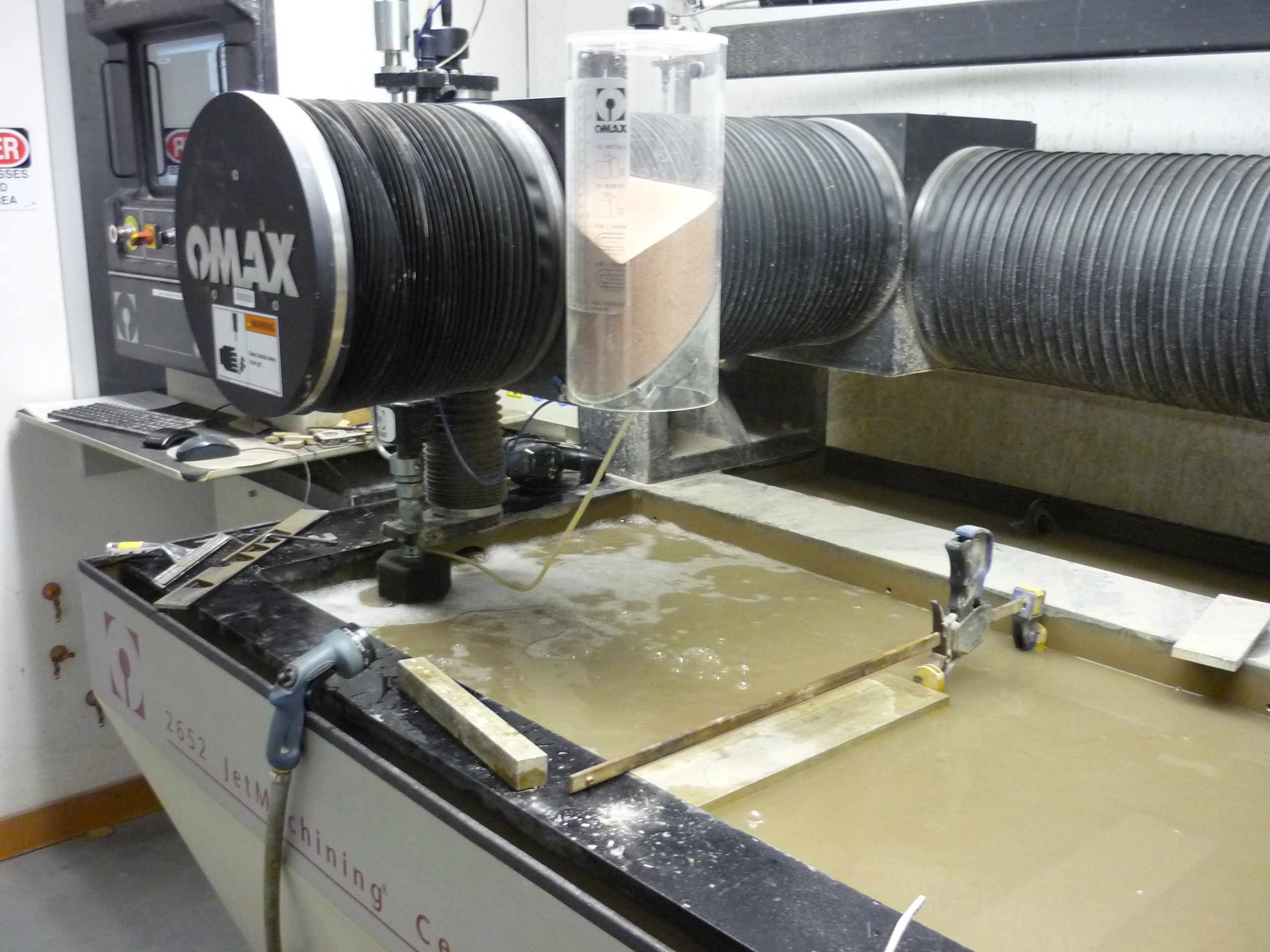
After being sanded and bored out to size, the shuffles had treads added. The treading material are strips of treaded conveyor belting, cut to the half-inch delrin width. The delrin is power-tapped for 10-24 screws using a dewalt. To speed this up, i ended up using ~3 drills, one for pre-drill, one for tap, and one for screwing in the retaining screw. Keeping in mind this needed to happen for 6 shuffle-assemblies and 3 spares, it can get time consuming. 
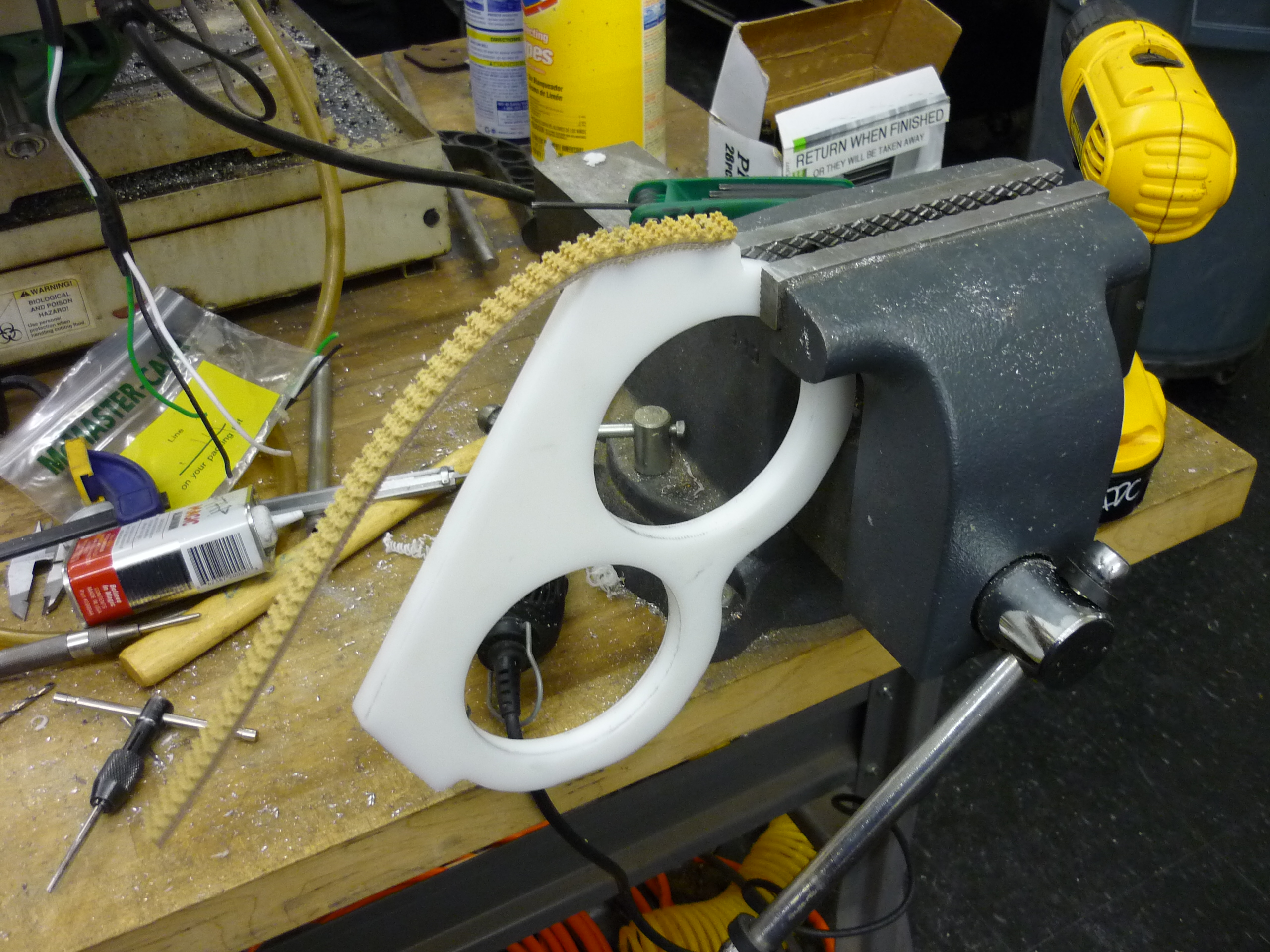
Assembling the shuffler-traction feet. The shuffle delrin was vice-clamped in place and a drill-tap-screw quick operation began. First one corner of the tread was screwed into the shuffle, then the treading was stretched while the remaining holes were drilled and tapped. This continued leaving extra of the tread material sticking of the far end, to be clipped by a bandsaw. 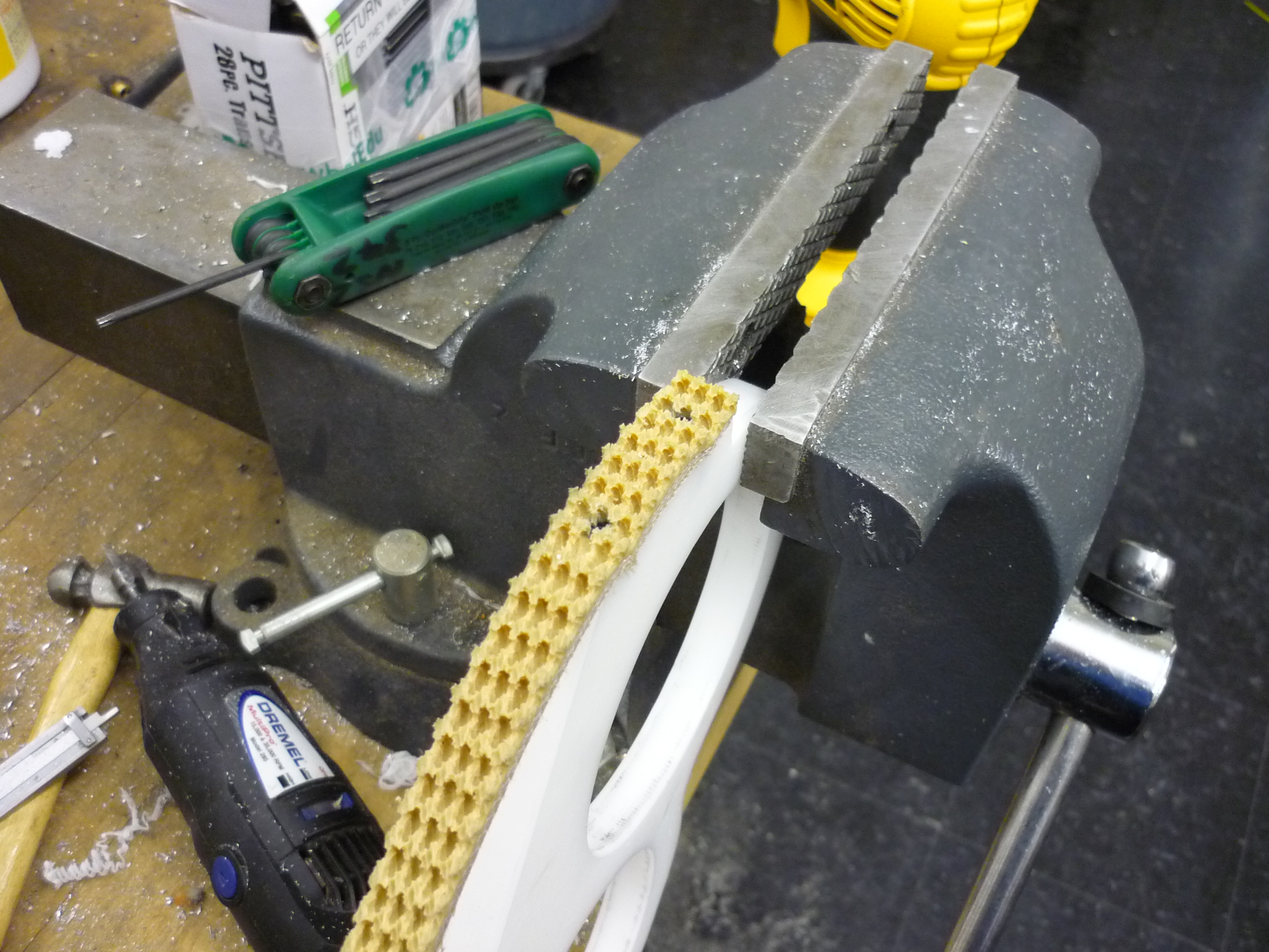
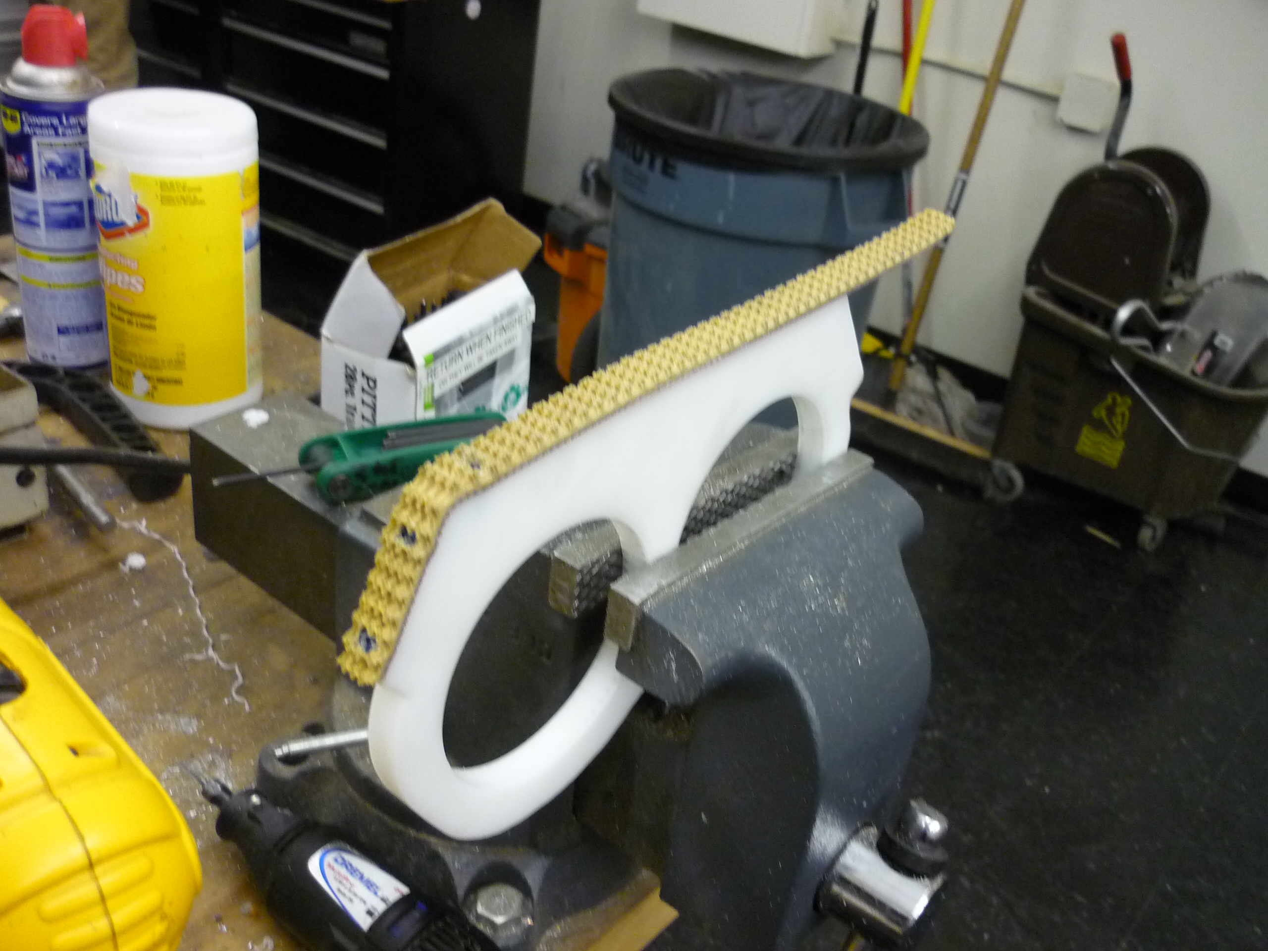
Some pearly whites. Here's the post-cnc'd treaded shuffle tracks. They are fairly gigantic sitting next to the steel-tube frame support. 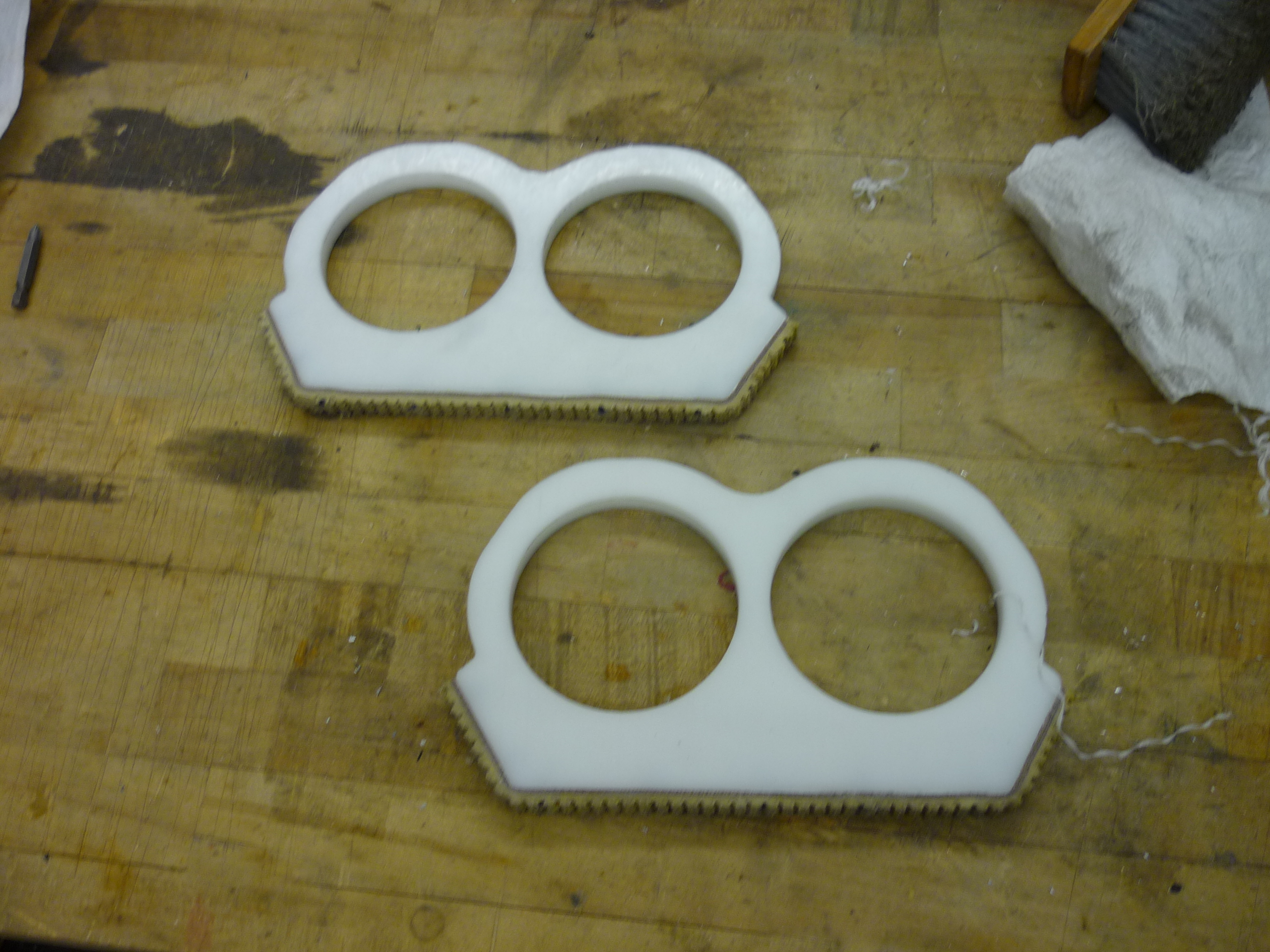
The last set of delrin shuffles were waterjet as access to a CNC was unavailable, post-machining of the cam circle was required afterwards. Delrin cuts suprisingly well on an abrasive waterjet. Shown close is the layout software and the parts being cut (submerged). 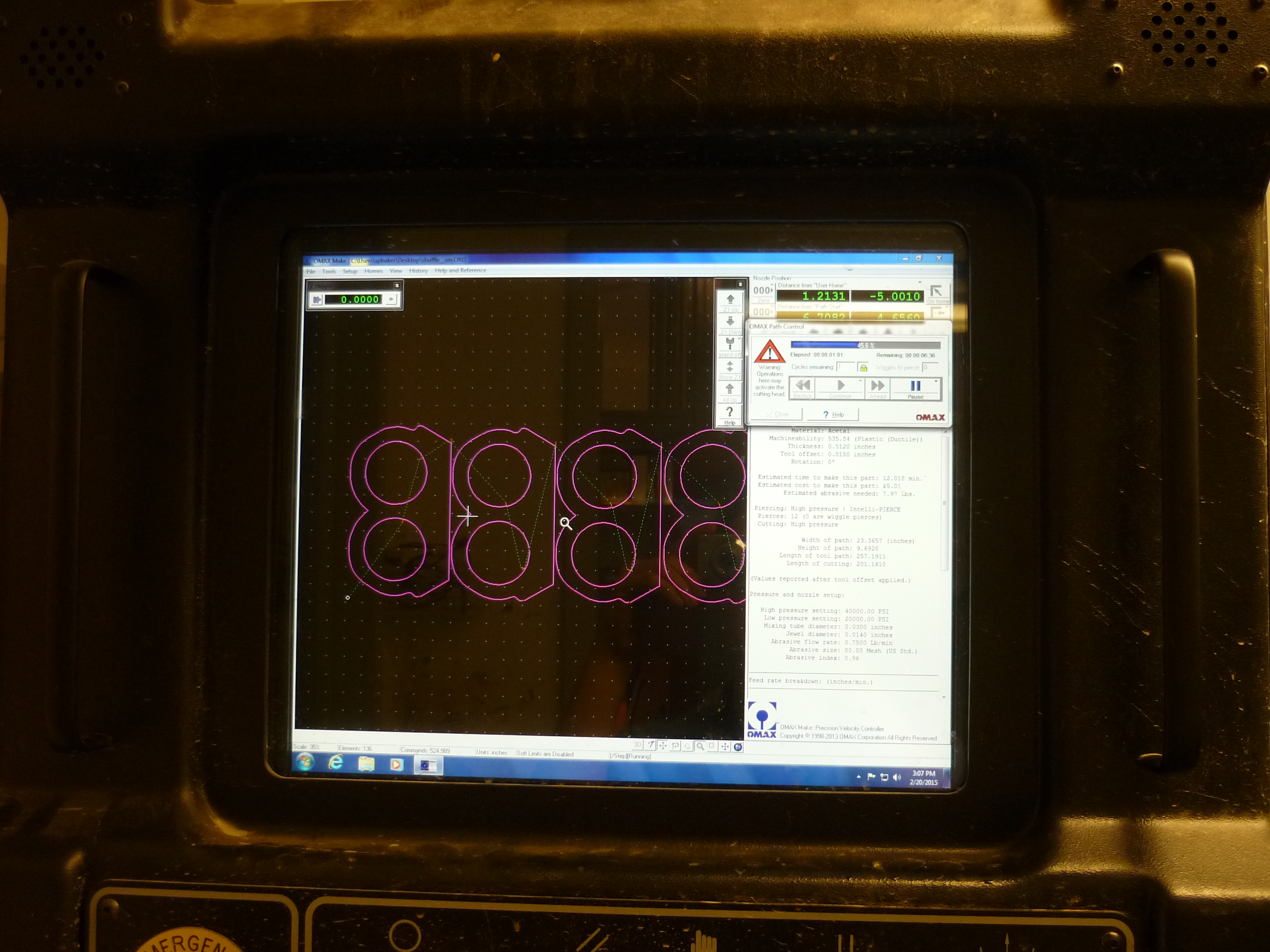
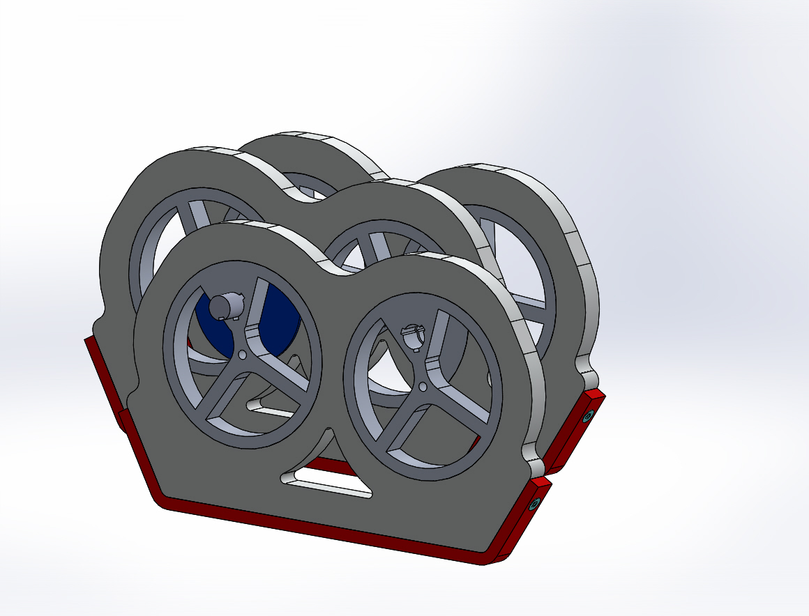
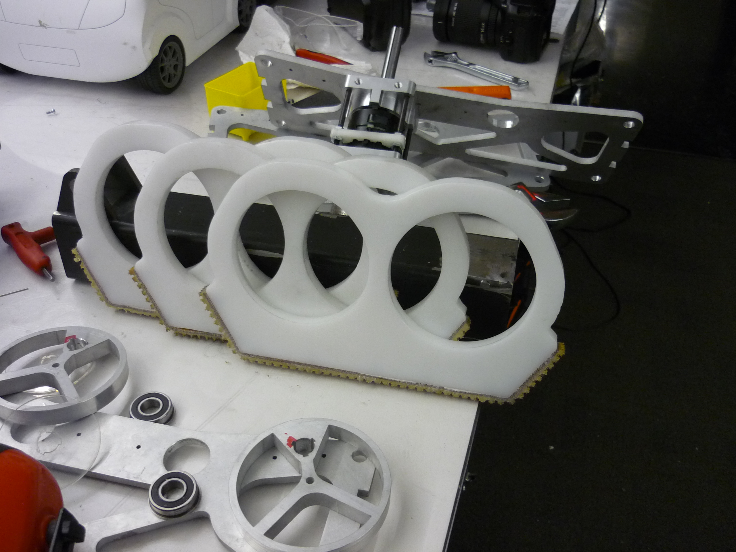
Putting the shuffle-sides together. The cams press into the delrin and have a 120 degree offset keyway. This design allows the same cam to be used in all the shufflepods which makes manufacture easier. This is the first time we noticed issues, the any machining tolerance issue stacks up and can cause binding. While aluminum on delrin was slippery, it was not nearly as slippery as a rolling element bearing. 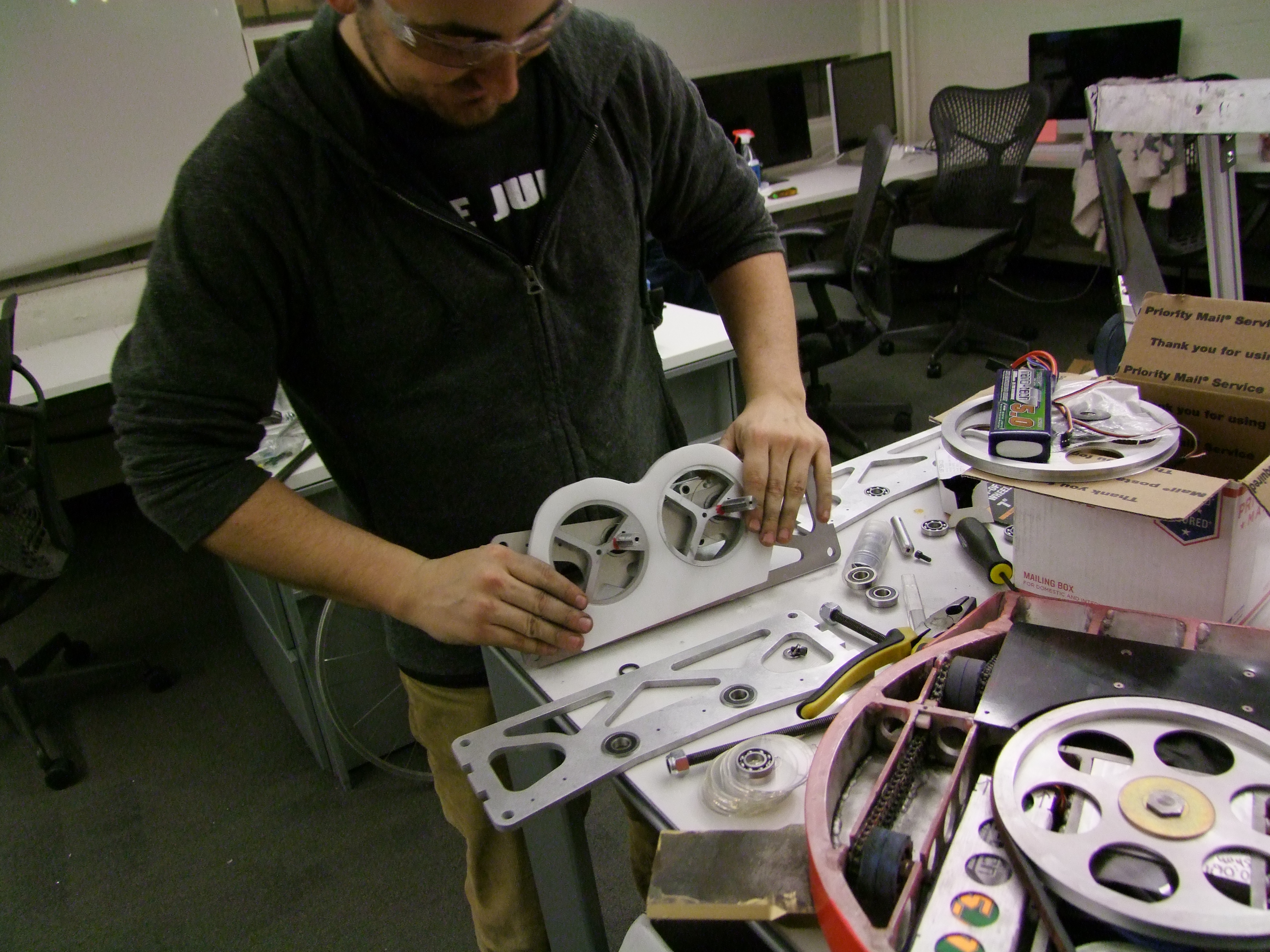

The build continued, stacking shuffle assemblies and attempting to not forget the parts order. More and more shuffle drivetrain components added, a lot of back and forth trying to get allignment to work well. Thin petg spacers are used to keep the shuffle cams and delrin apart from each other. 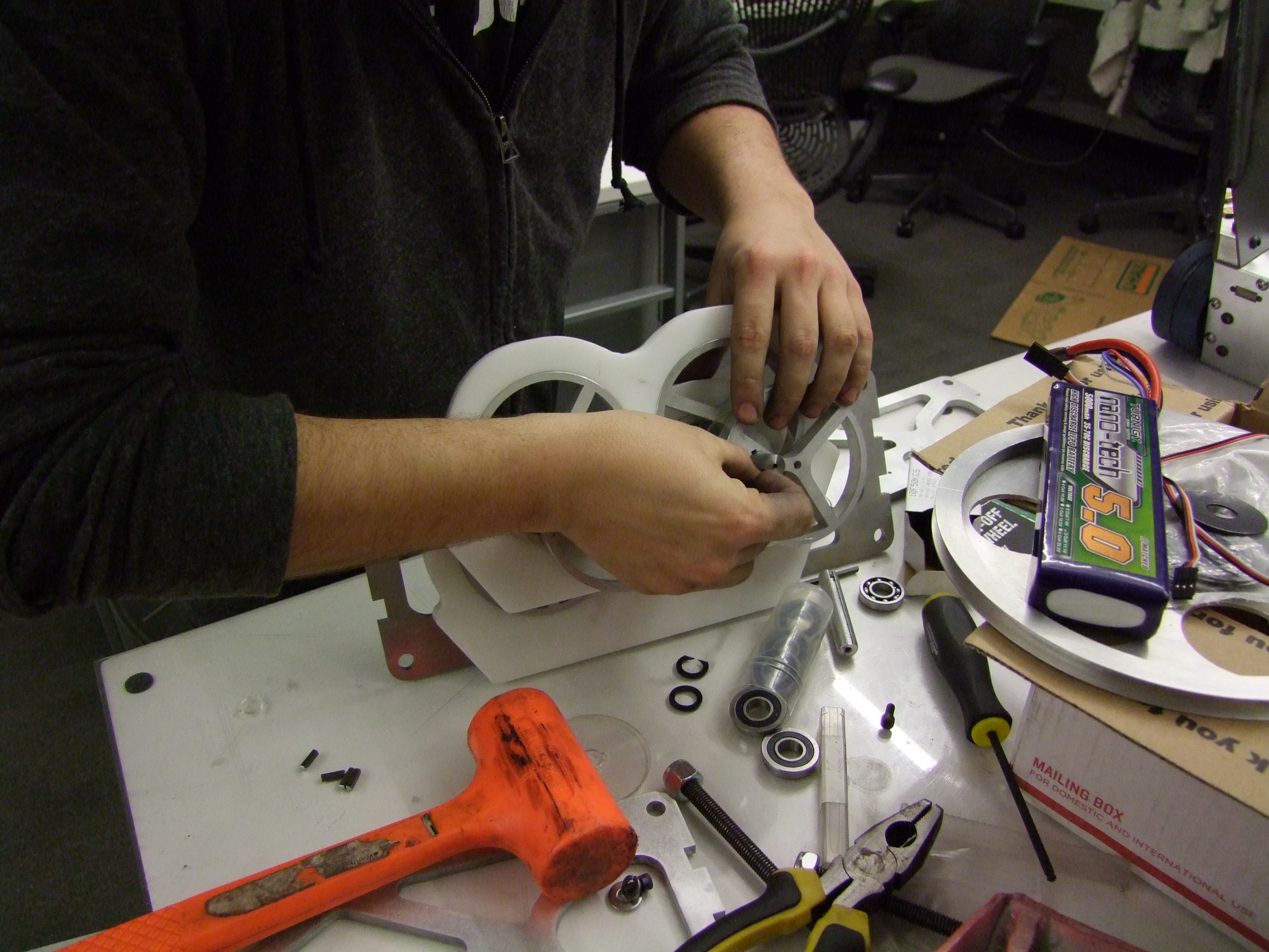
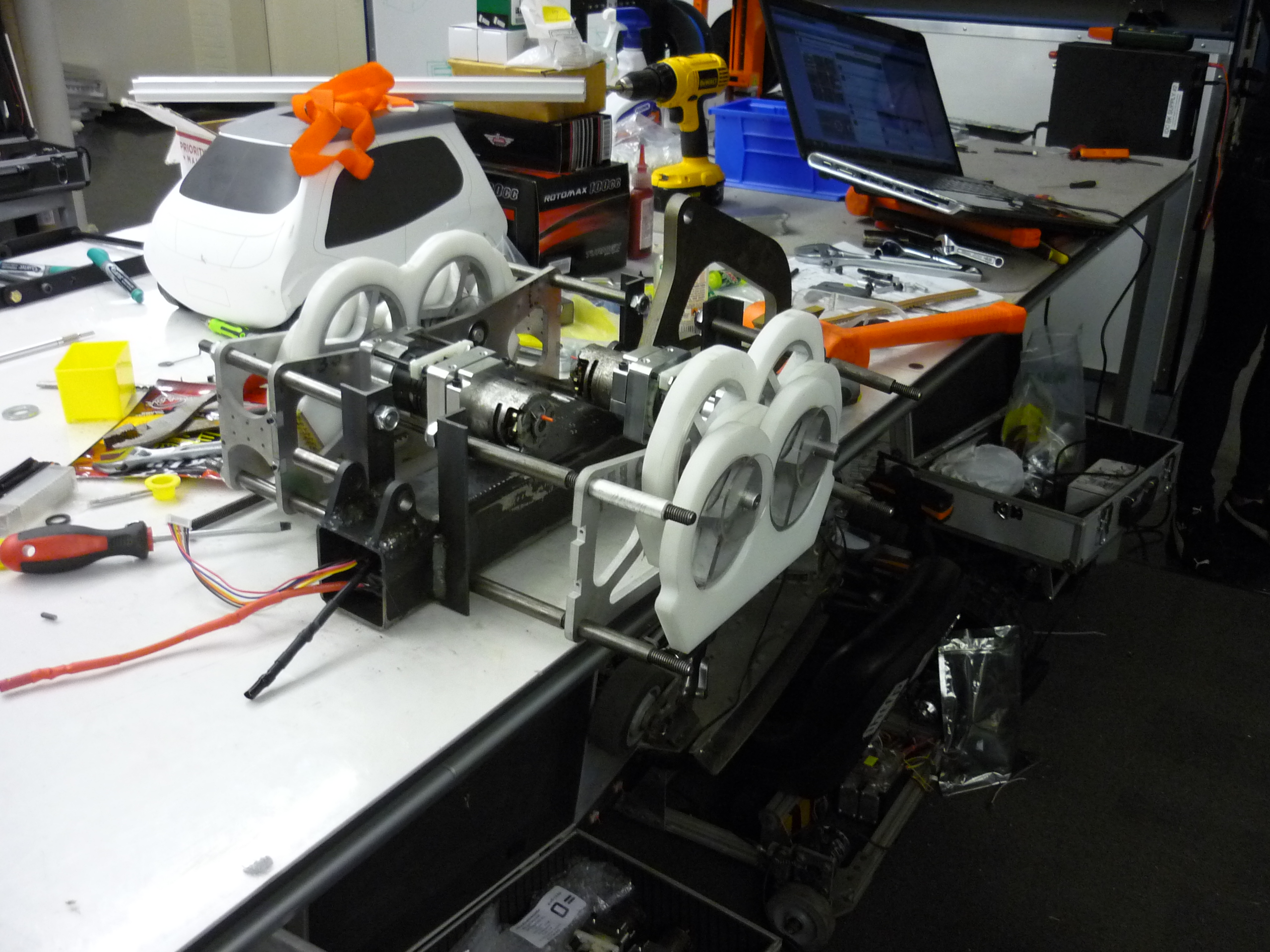
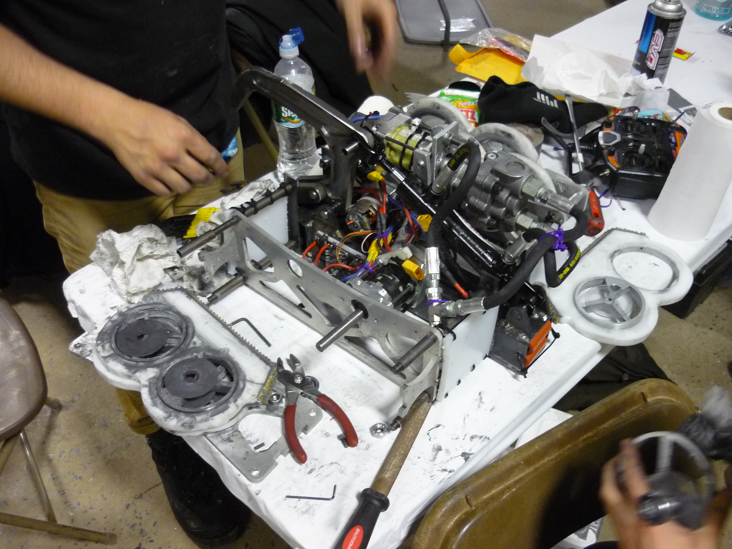
ITS TESTING TIME. The first spoolup of the shuffles happened ~2 days before competing out at motorama 2015, spray lube was added to coerce the shuffles from jamming. 
Shuffle Layout & TestingThe shuffle mechanism in moving, see-through form. Note the cam design contains 3 mounting points for keyways, allowing the same CAM to be used on all shuffle legs. Shuffle Test 1. One of the early tests of the shuffle propulsion system. Just needed some lubricaltion, that proceeded to spray everywhere. BatteriesThe main power for the propulsion and weapon was sourced from a 6S 5.8AH LIPO, care of 'big chucks nuclear lipo aresnal'. We had planned to have adequate space for battery + controllers living inside the structural frame-tube, however, due to parts not arrivig ontime, a thicker tube was used. This forced the battery pack to be re-arranged to mechanically fit inside the tube. 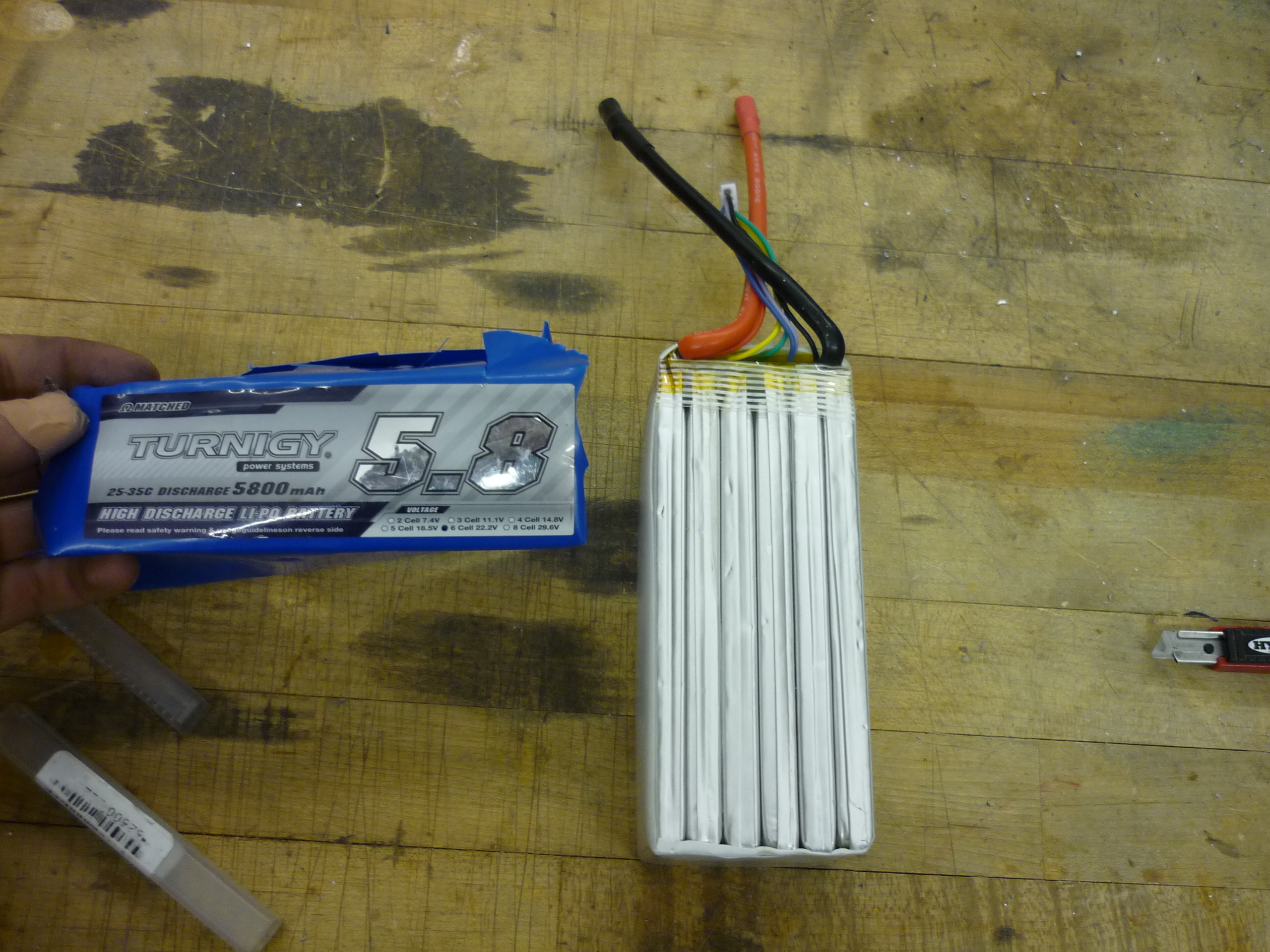
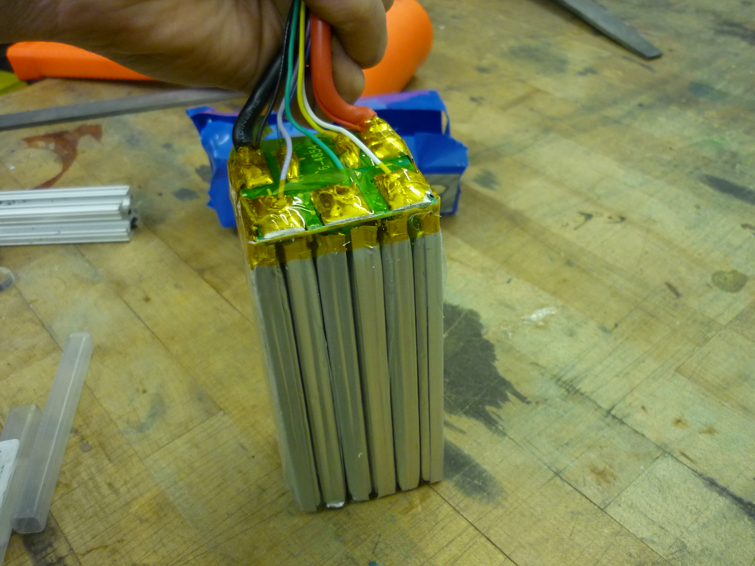
The pack was de-heatshrunk and split into two 3S modules. These were adhered to a thin polycarbonate sheet (to allow the batteries to be removeable / slide in on a sled). Interestingly the top of the battery assembly was connected via an FR4 PC board. Seperating the cells is actually fairly non-trivial. A small amount of Acetone was applied with a dropper between the cell groups and light hot air was used to assist in pulling them apart. It's fairly easy to tear the mylar pouch, so be careful! 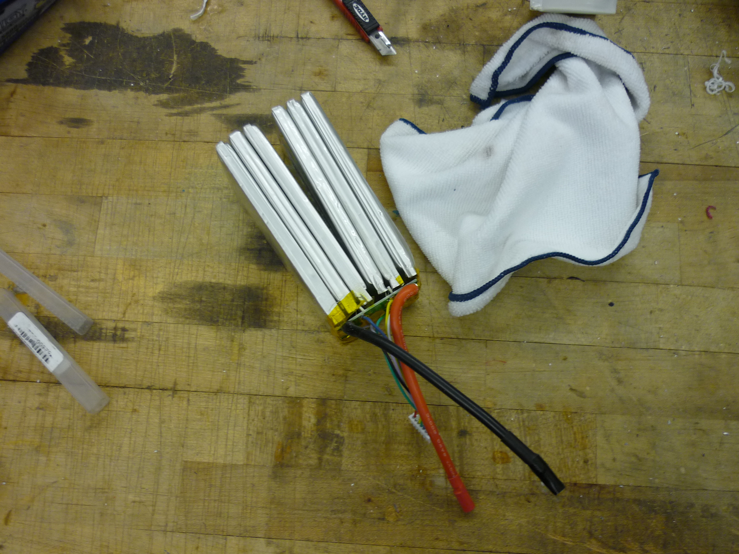
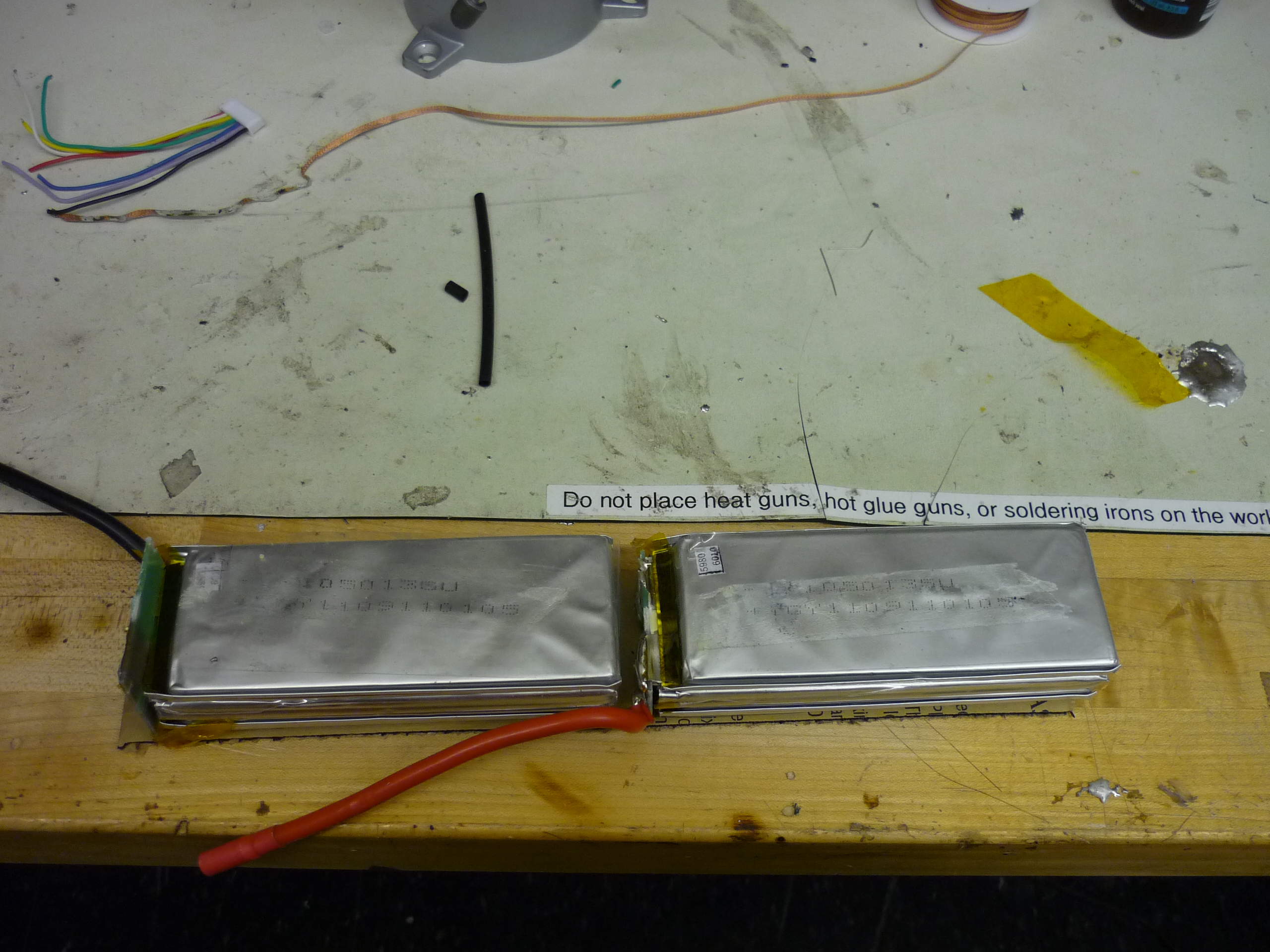
Some attempts were made to make the pack more legitimate, however due to volume constraints, a pile of electrical tape and insulating glue was used. Note the balance leads were brought out to the opening for balancing, the battery was left in the robot to charge. 
Shown is the robot 'charging in place'. A hyperion 1420i charger-suitcase was used to bring the bot up between rounds. 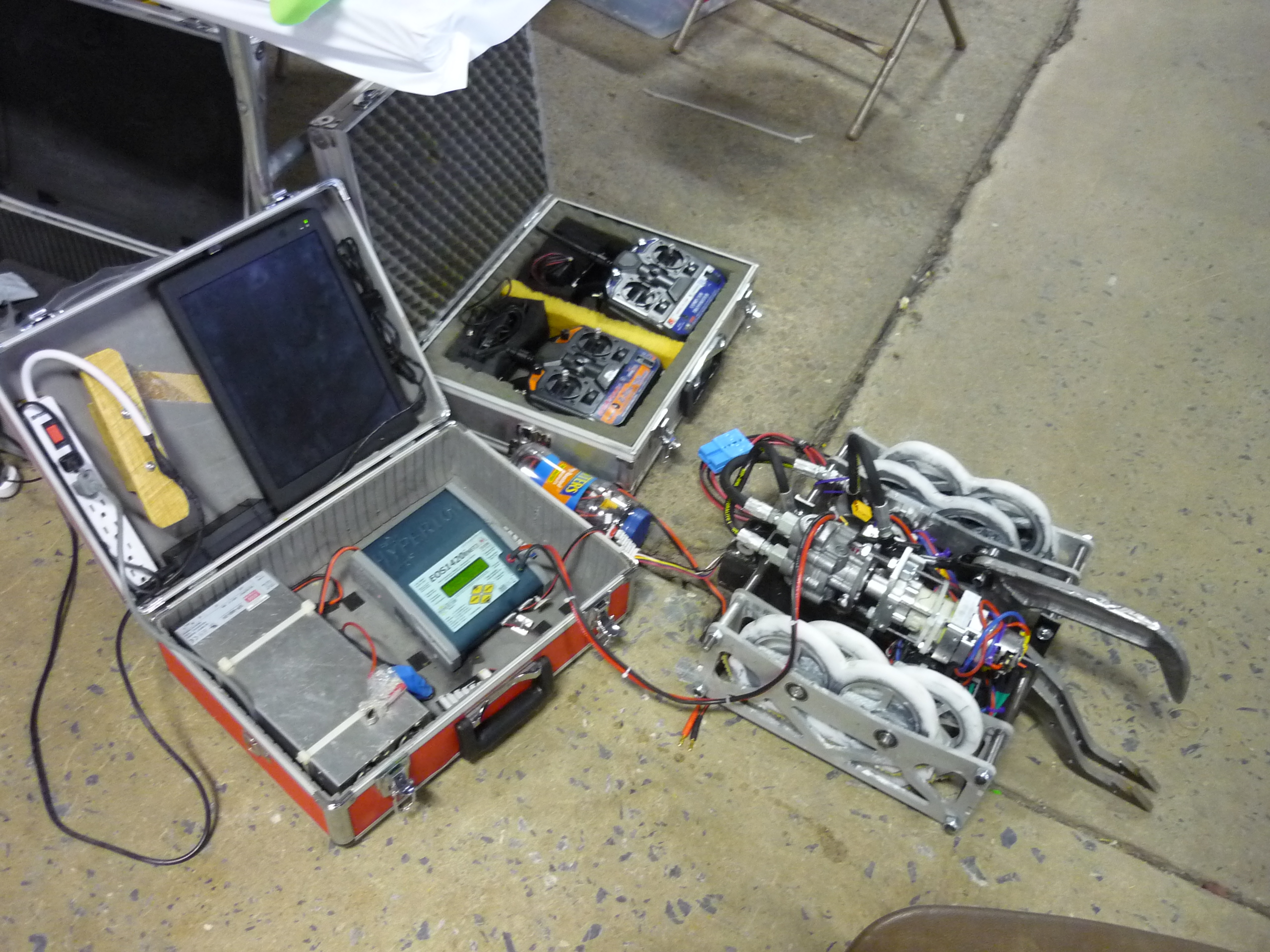

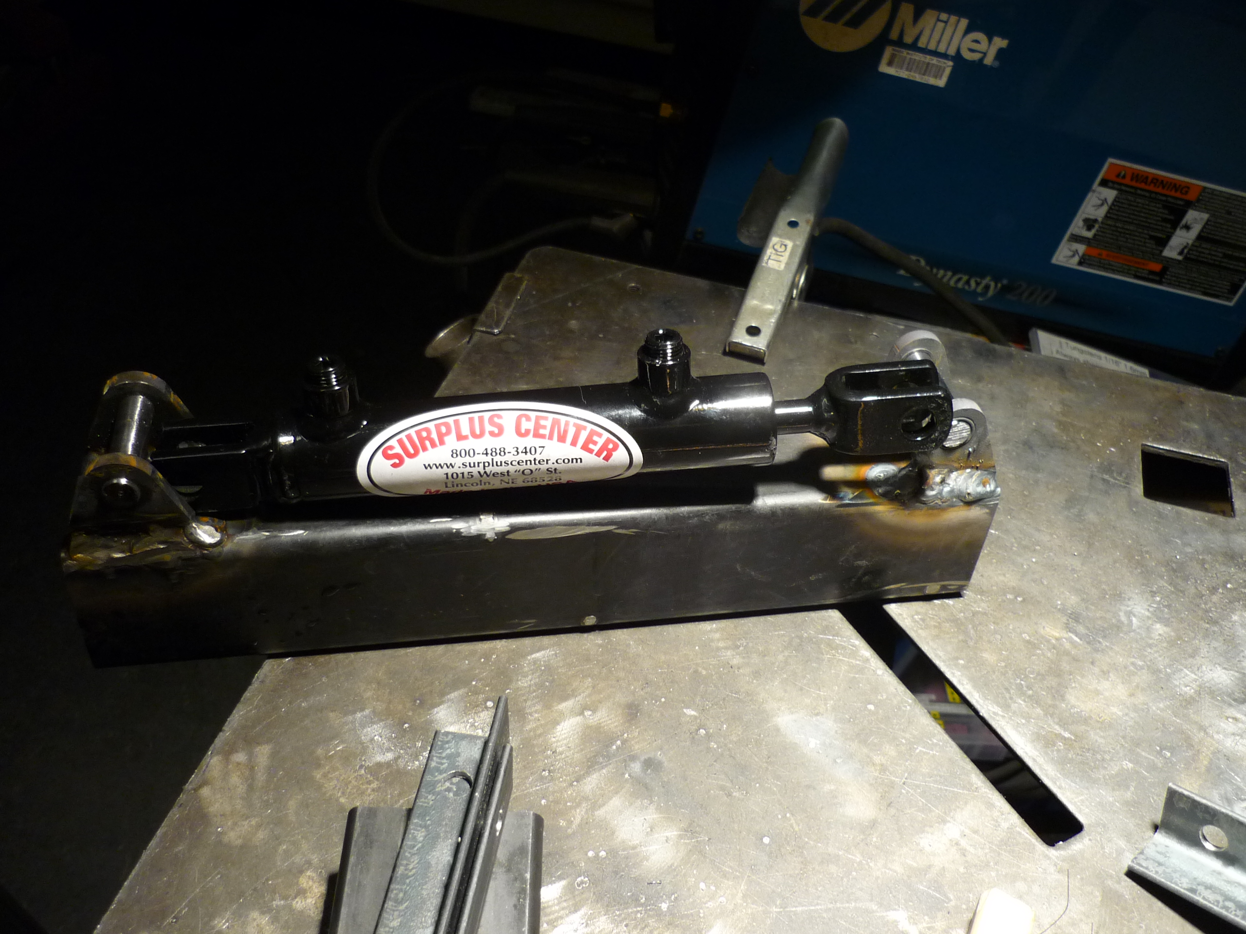
Crush Actuator TestCrush actuator testing, one shuffle side removed. Note how the single hydraulic actuator hinges on a 2-bar linkage, allowing the crushing action to also have a lifting force. Paper was used around the fittings to prevent any leaks from spraying violently. 
Crushing the closest thing we could lay our hands on. We crushed a free post office cardboard box with ease. Design Verification Testing Complete. SHIP IT. Assemble the Beast<documentation pending> 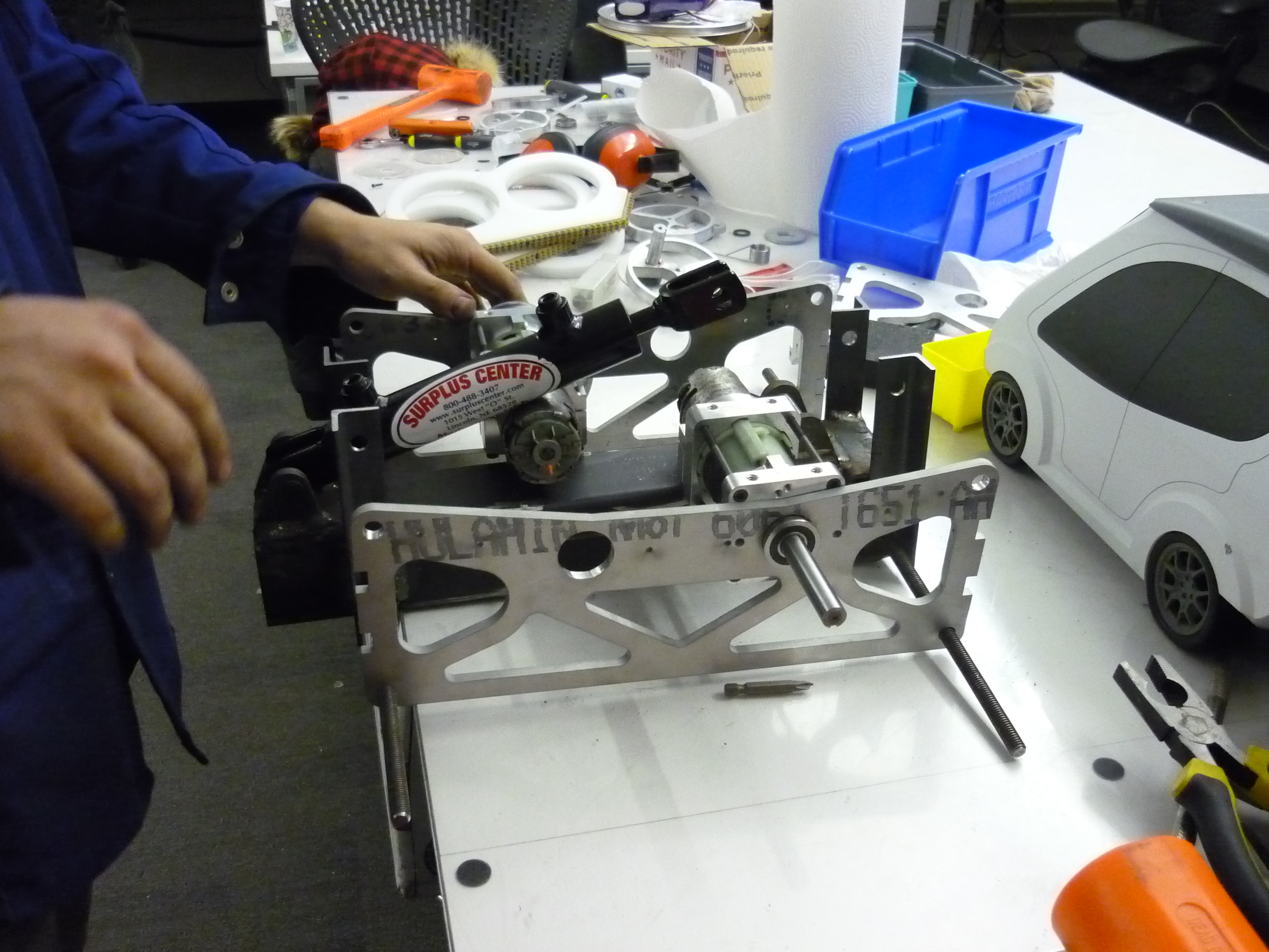
Find out that it's too heavy. Here we stare at the bot and the scale. It came in at 46 out of 45 lbs. We were tired, there were more things to add and hydraulic lines to fill. The reinforcements were called and a few hours later Rob Reeve and Birkel managed to manually interpolate curves on a bridgeport and cut mass from the main chomping head. AND LO' we were right about at 45lbs! 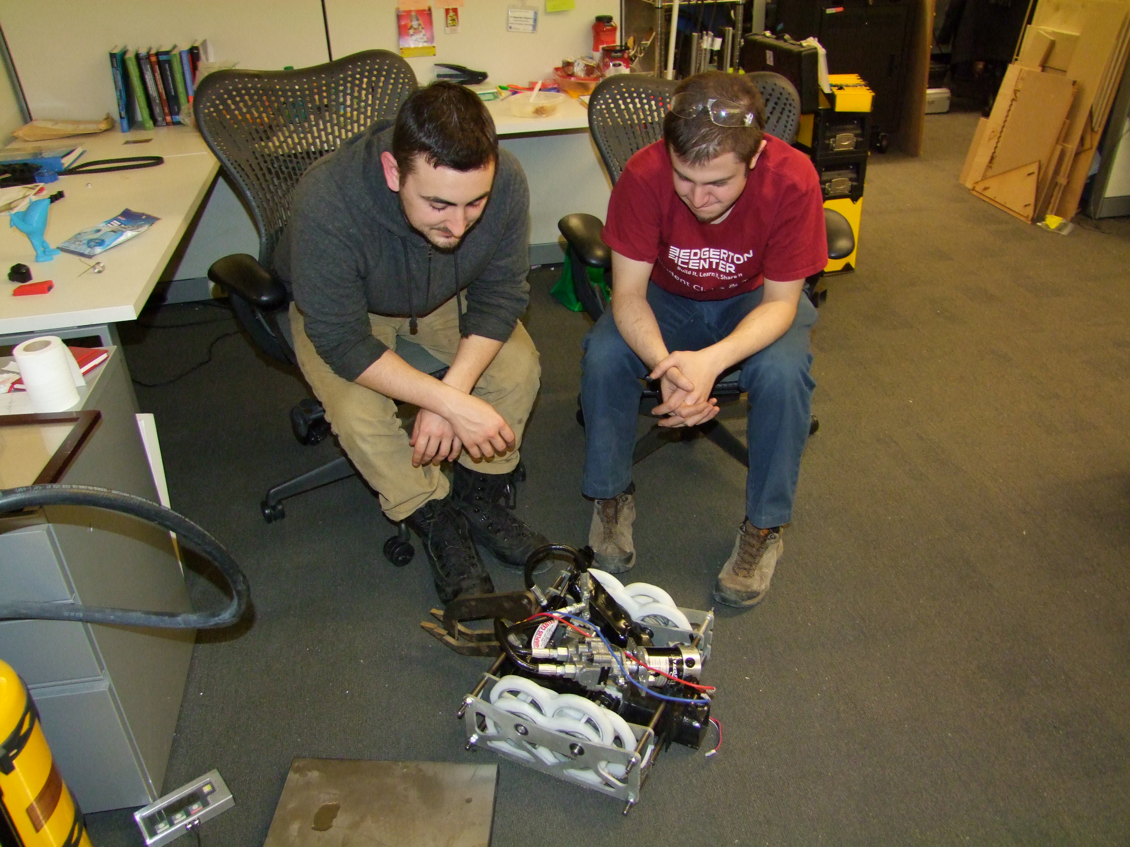

Motorama 2015ITS ROBOT FIGHTING TIME, Kinda. Myself, Charles Guan, Becca, Bercu, Fred, Berkowitz and Cynthia headed west to the mighty state of Pennsylvania. We proceeded to get to the event, set down our things, plug in our tools... and fall asleep on Rob Maseks Brand new Trailer after road-tripping for ~8 hours through the night. 
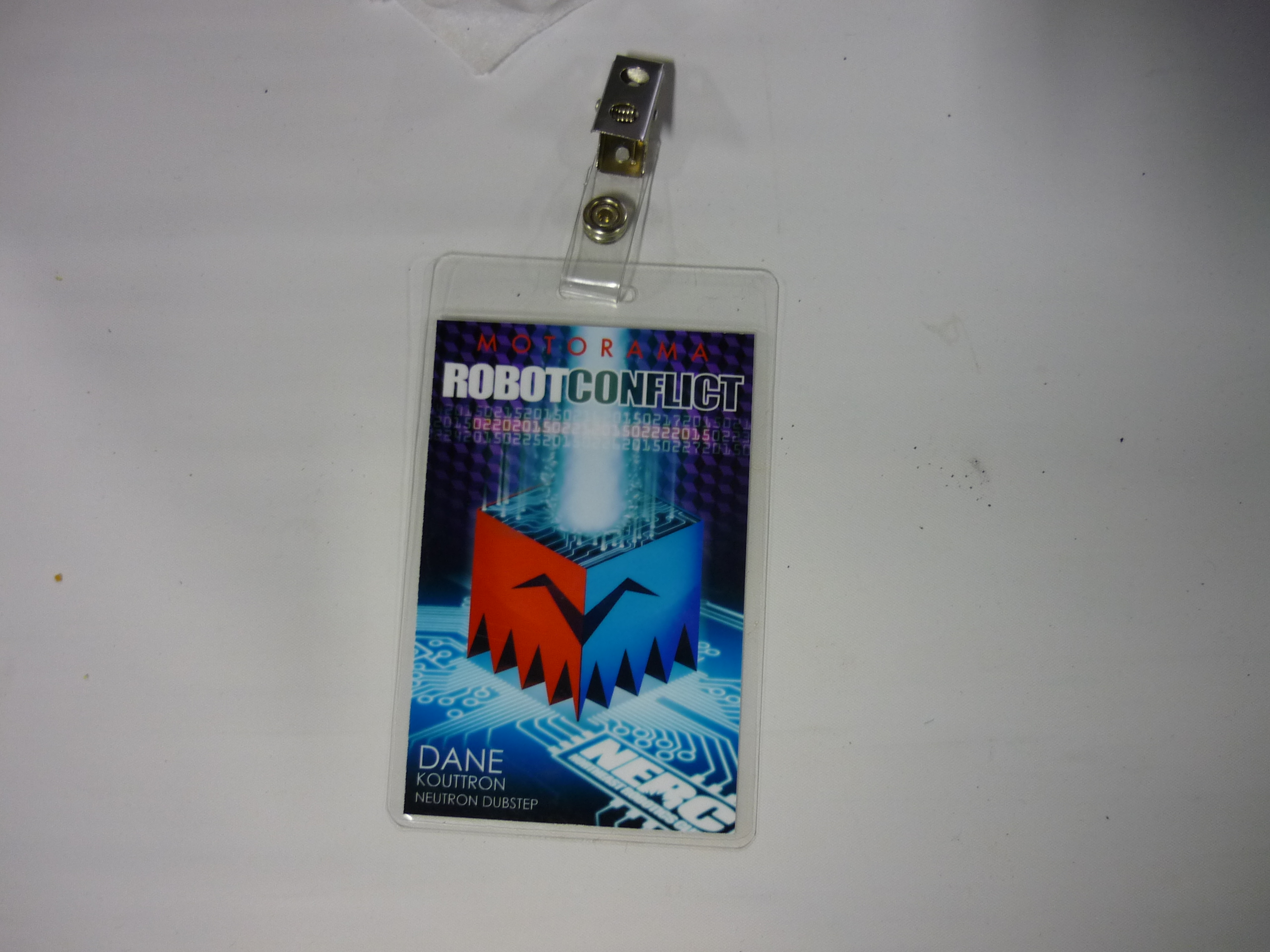
Motorama is a special place. There's amish folk making hotdog-pretzel buttery deliciousness, there's lifted jeeps and threre's kids watching robots on a tv in front of a robot arena. Its a great time highly reccomended. The robot-fighting folks are the odd-ducks to the native pennsylvanians and its always nice to see a crowd peering in from the motorcross events at the robot contraptions. 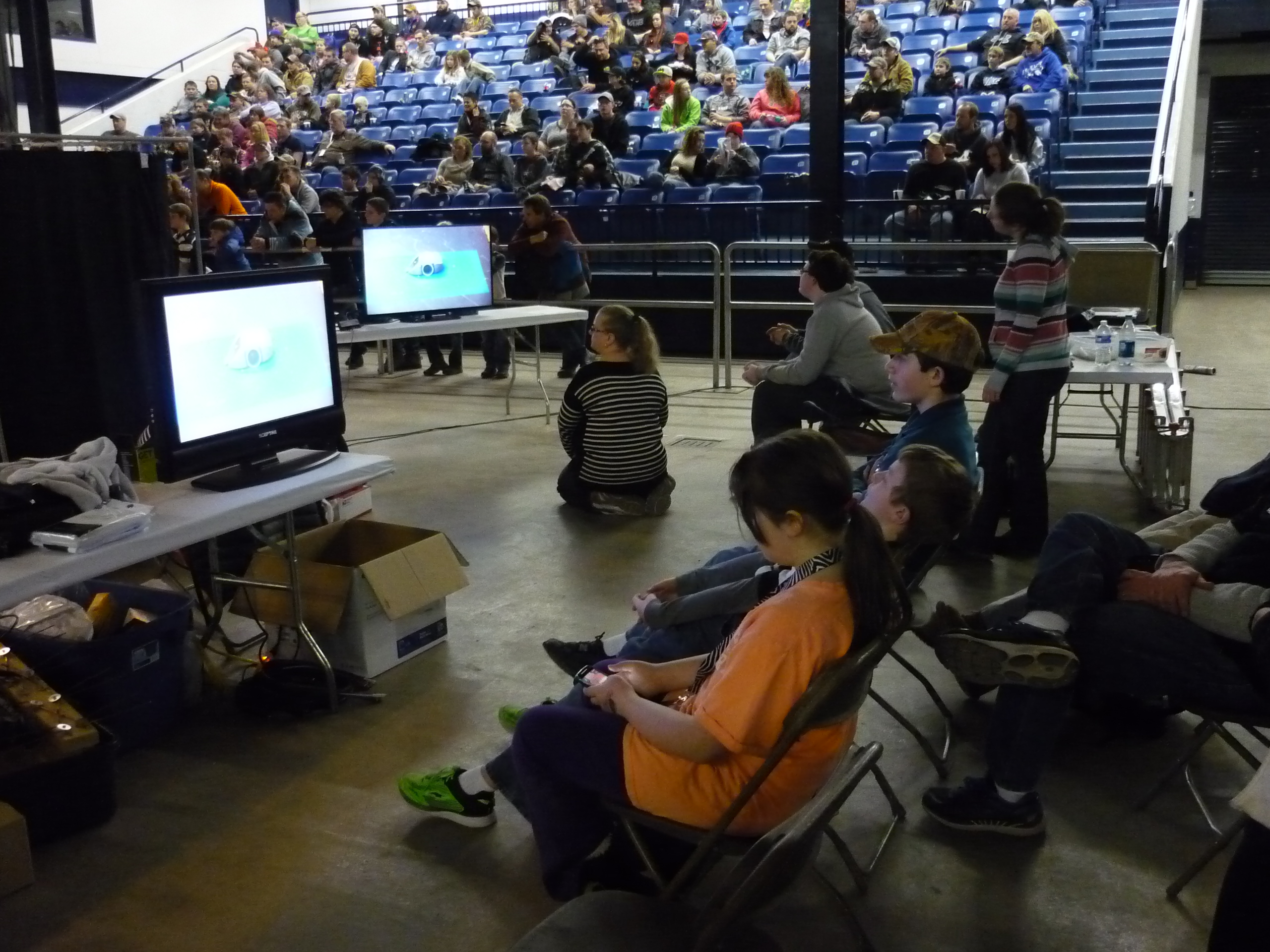

Pre-fight Glamour shots. Special thanks to Dale's portable photobooth. We may have leaked a bit of hydraulic fluid @___@ 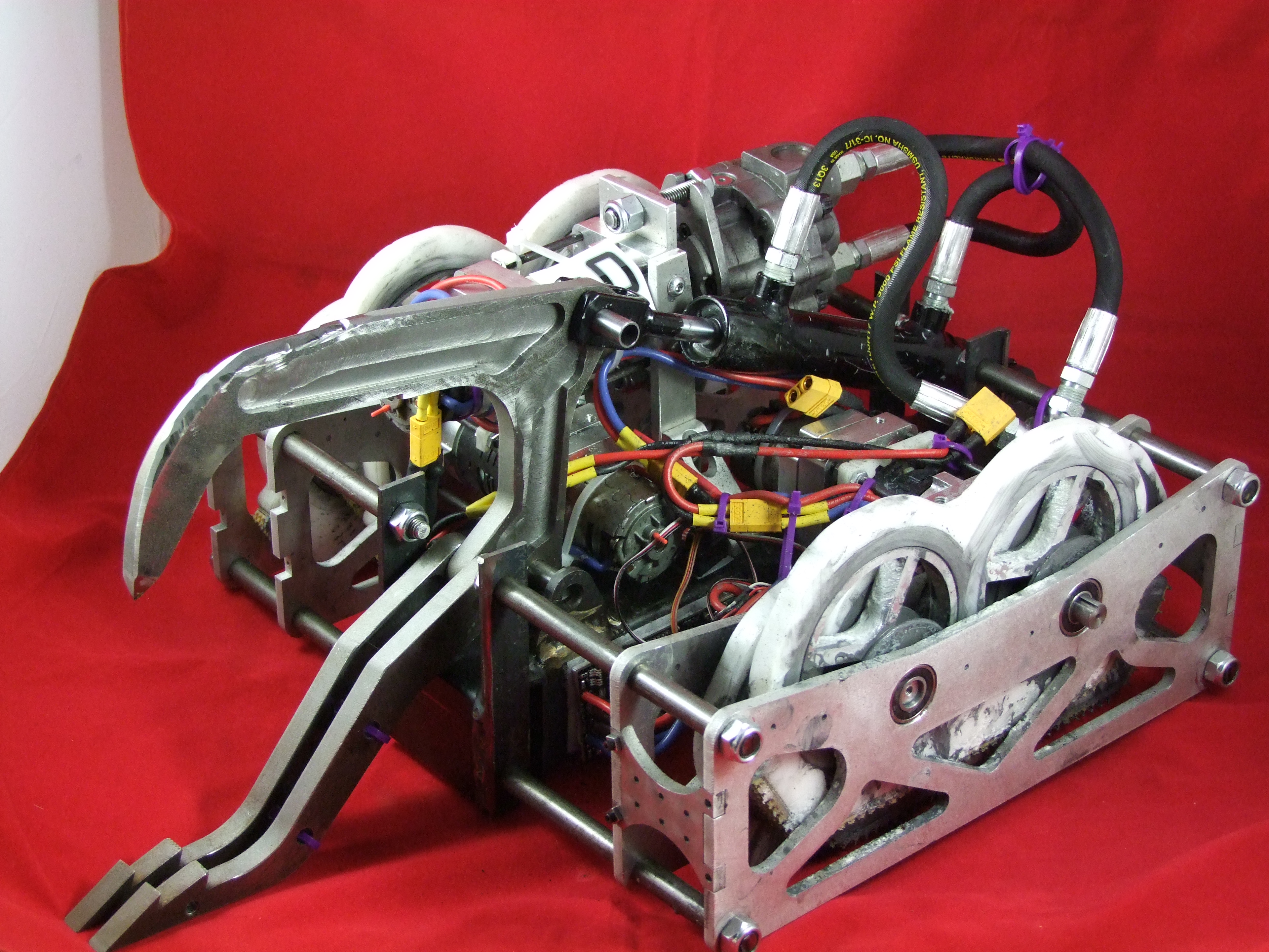
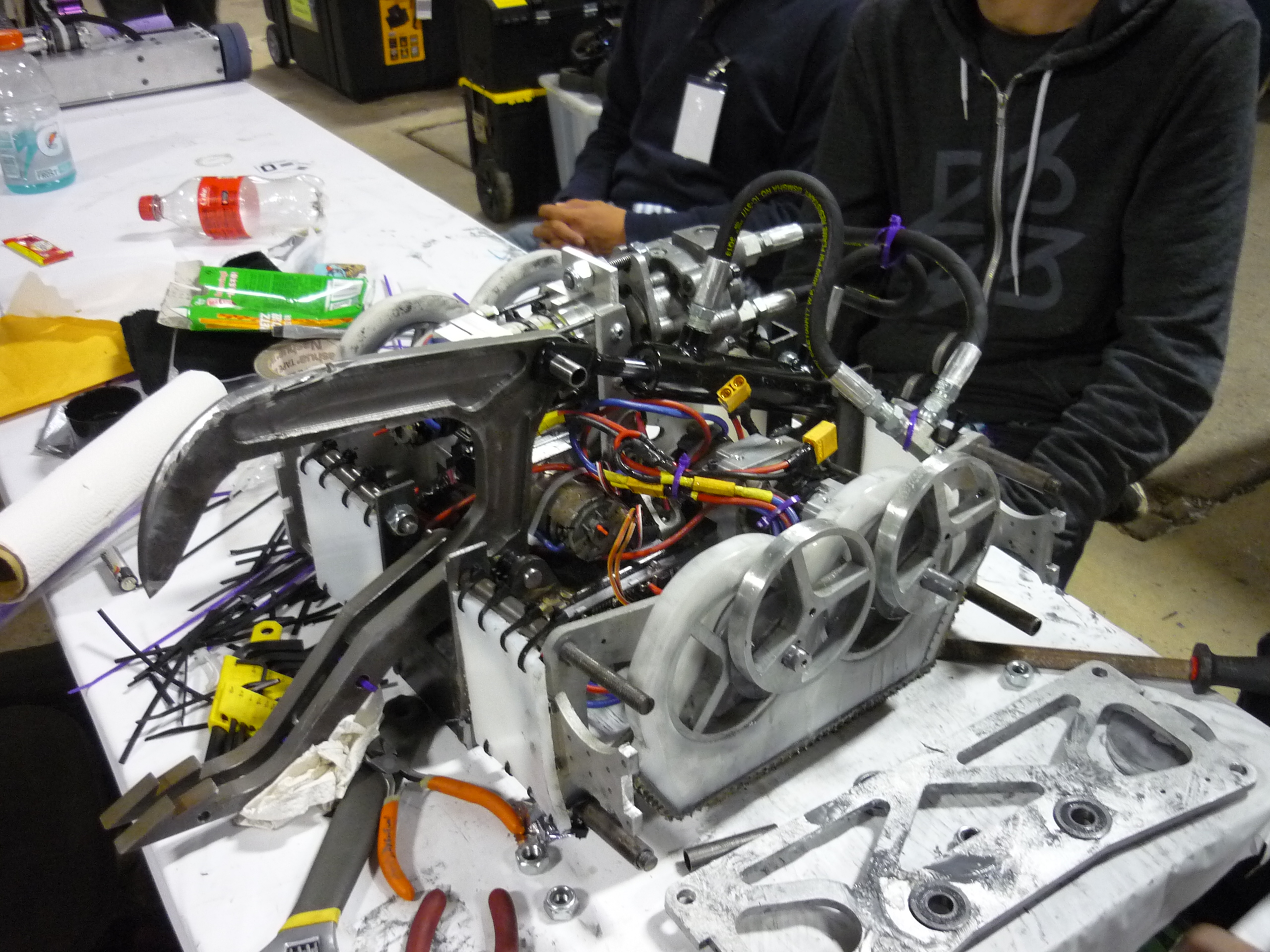
The beast awakens. Here we are at our table, unpacking and getting everything ready for a once-over. Such a pretty bot. 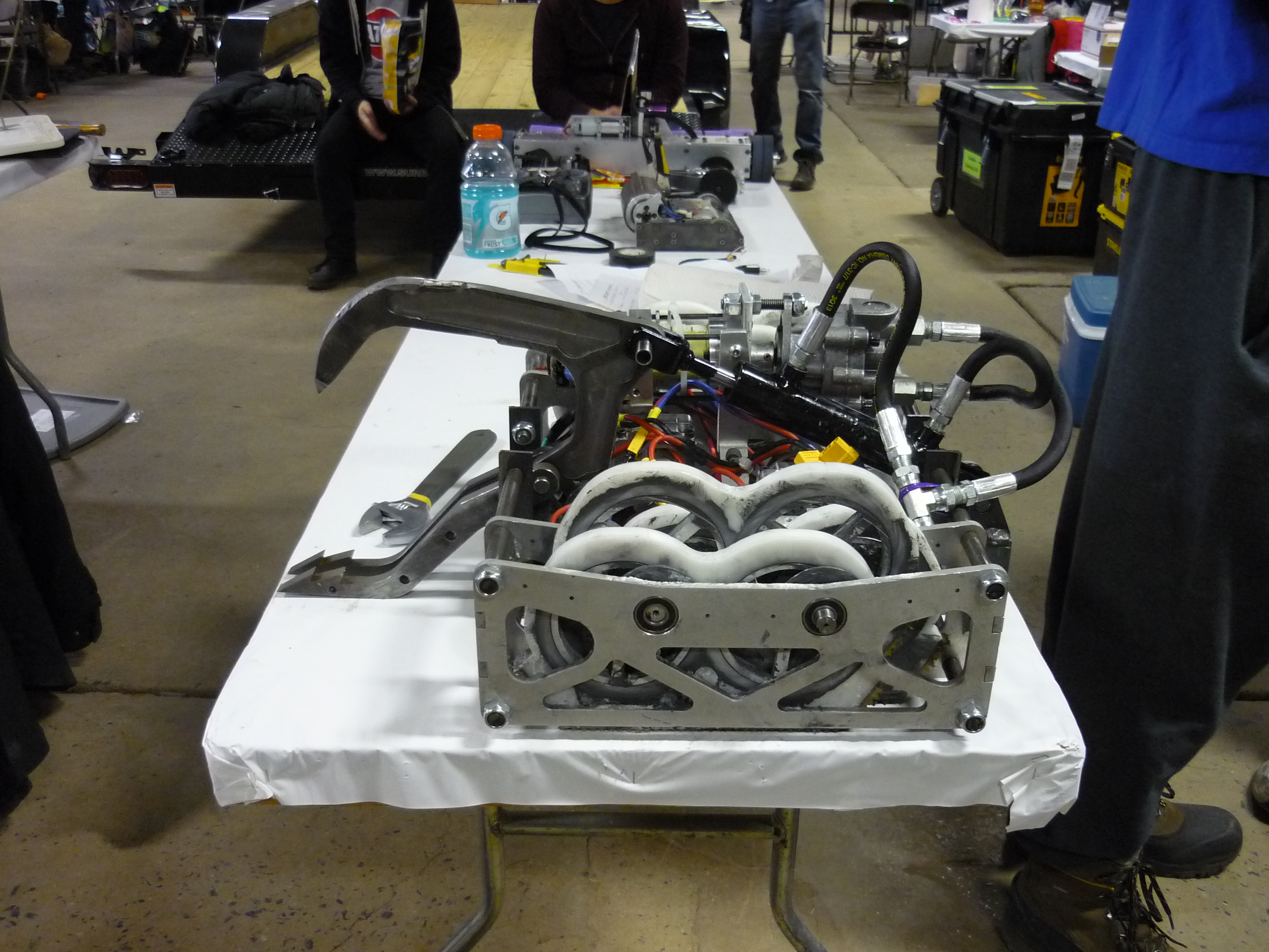
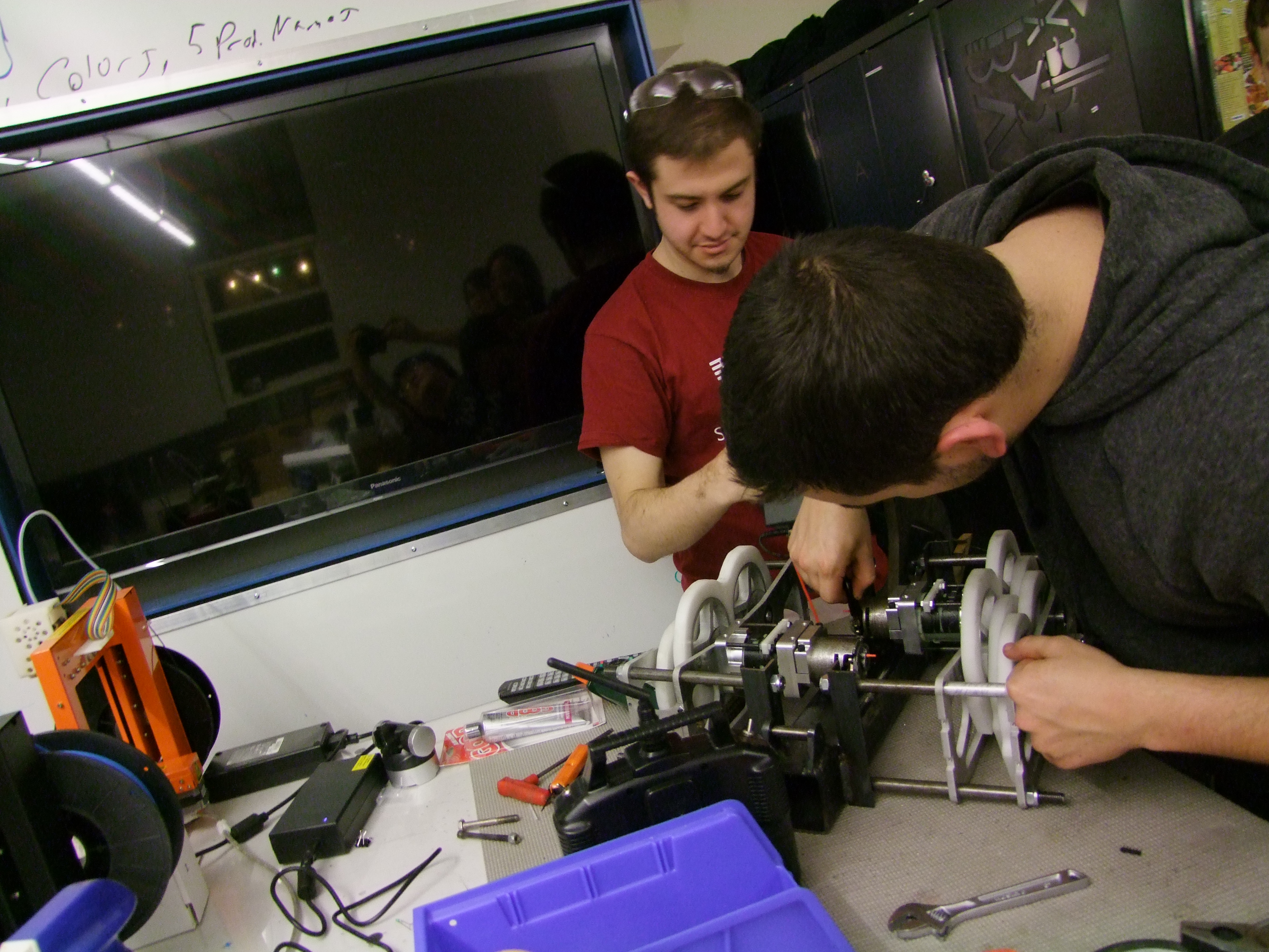
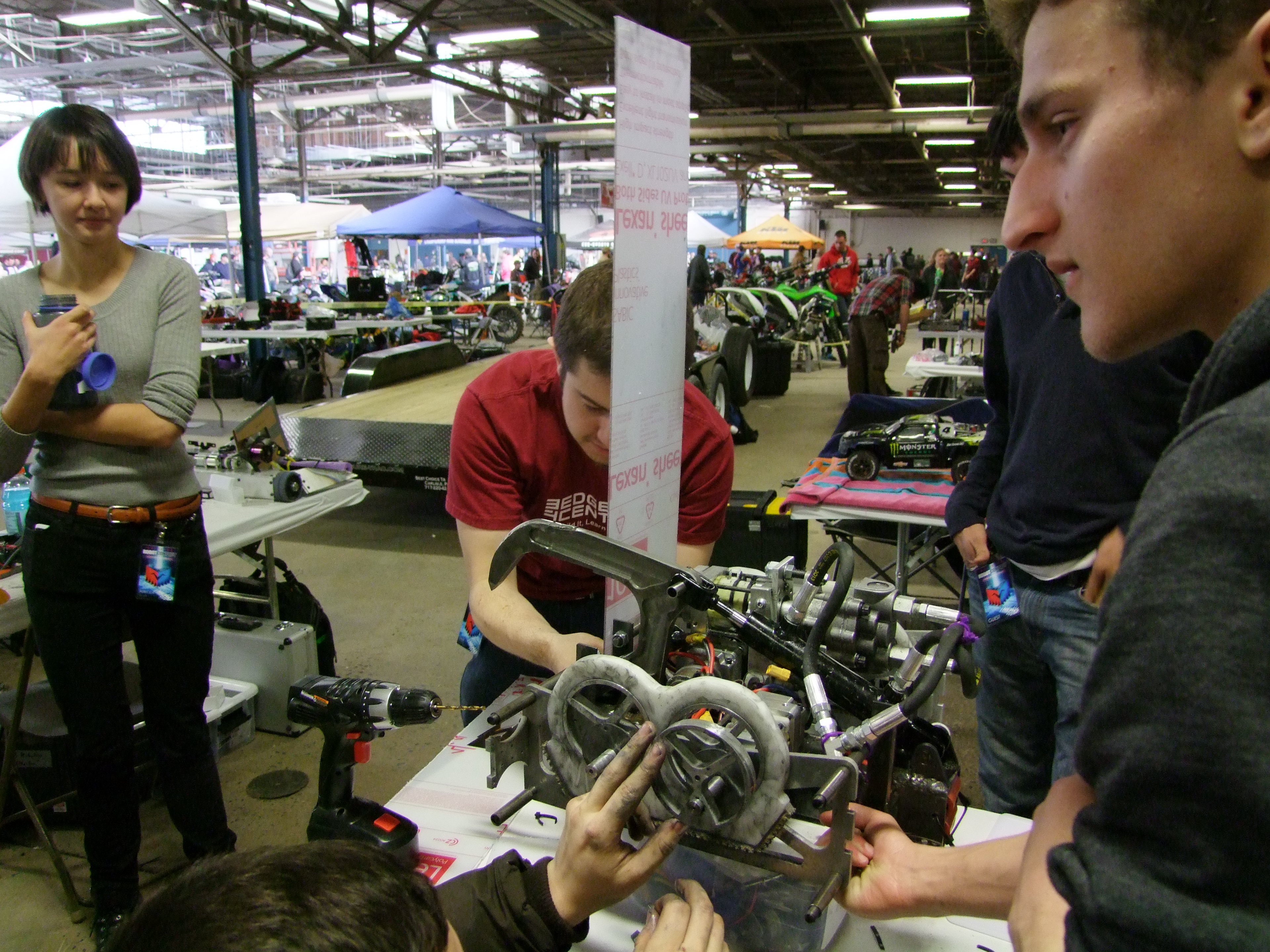
There were some minor adjustments to be made. We ended up rebuilding the shuffle mechanism a few times to try and get any bound sections to 'clear'. I ran to a moped-cycle-atv table and found some chain-lube for $5, this became our new problem-solver / mess creator. Thanks moped folks! 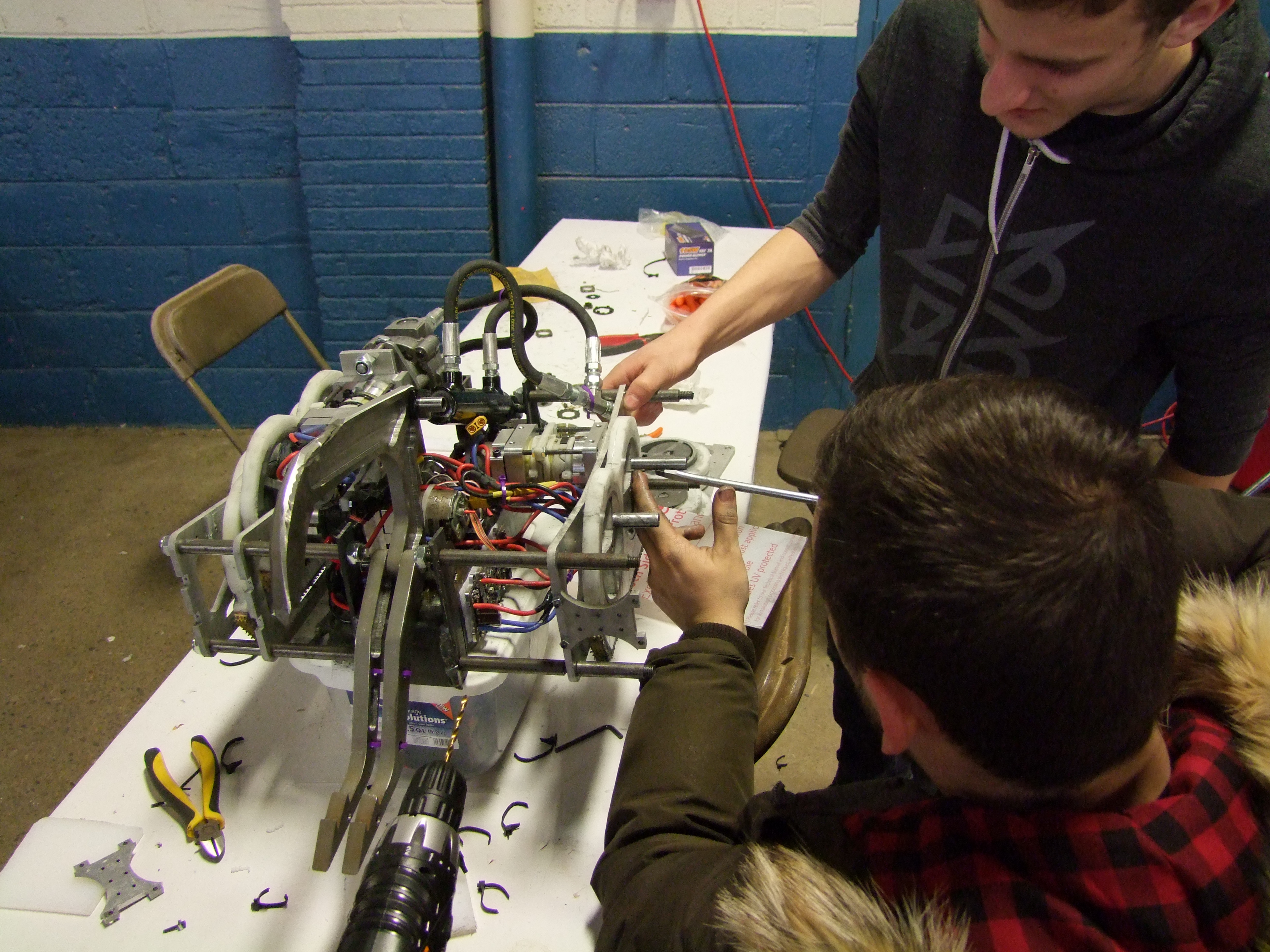

Taking appart the shuffles. Disassembling the shuffles was a pain. We quickly came to the conclusion that the shuffles should be modular and removeable to make it easier to work on. The assemblies do require a decent-tolerance mate between the cam's and the shuffles. Unfortunatley all shuffles and cams arent completley identical. There was some back and forth play to get the shuffle assemblies to play well together, it was greasy. 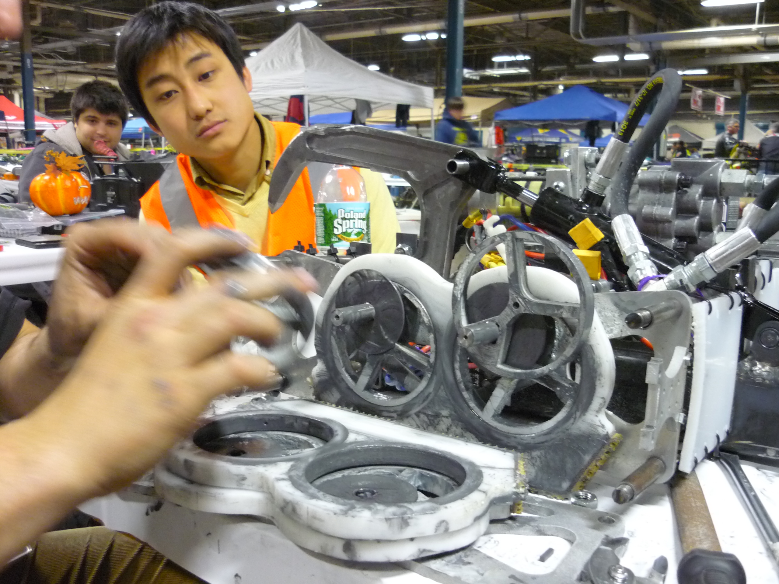
Shuffles coming back together. Small lasercut petg 'washers' are used to keep the opposing shuffles apart from each other. 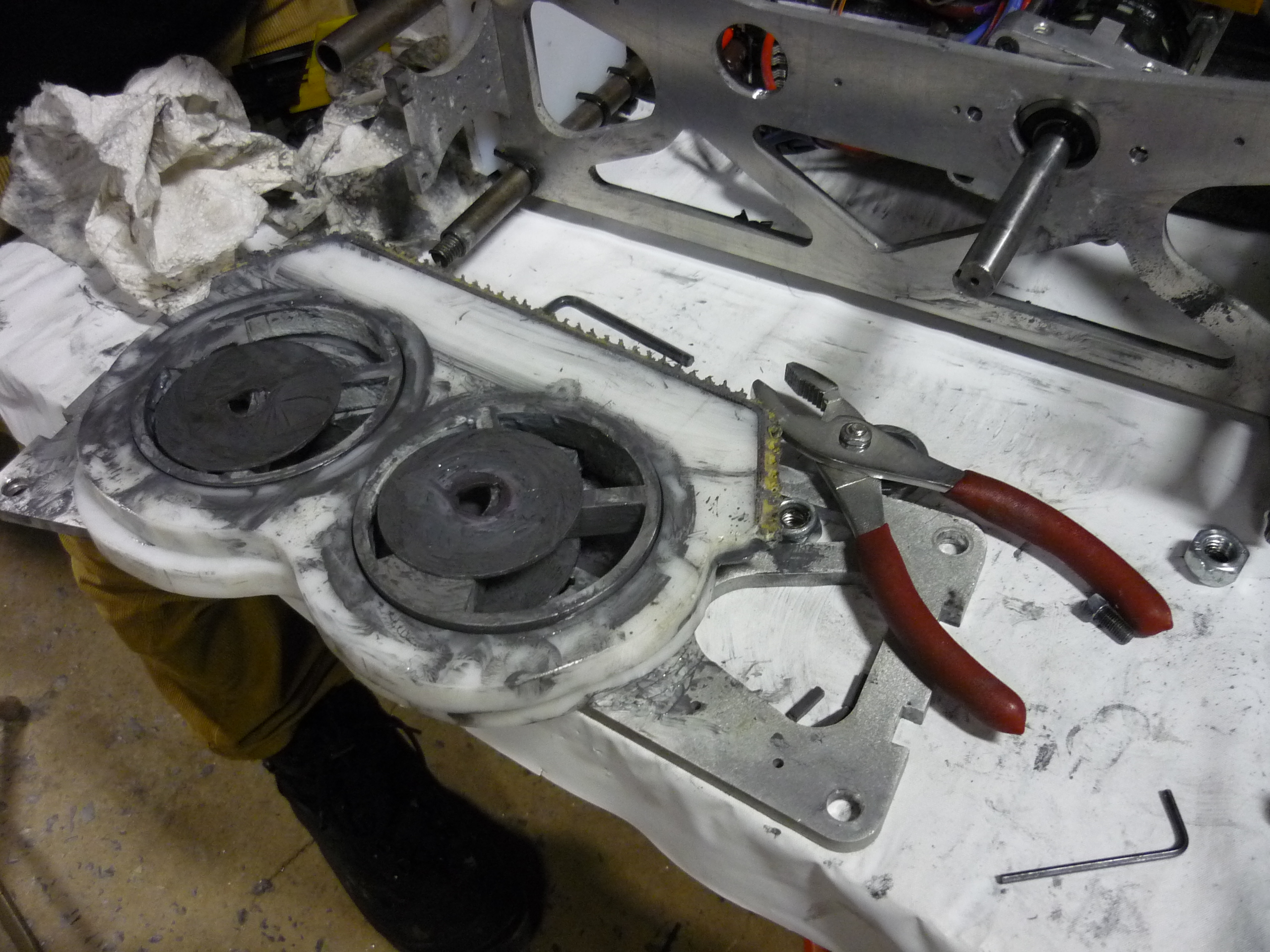
More teardown and rebuilding. Allignment and reconfiguring continued. At this point a 'modular' or removeable shuffle drivetrain was brought up. Most noteably, not requiring to manipulate the whole bot every time we wanted to remove something would have been excellent. The structural allignment members of the shuffles were part of the frame. Removing this constraint would be a step forwards for the next iteration. 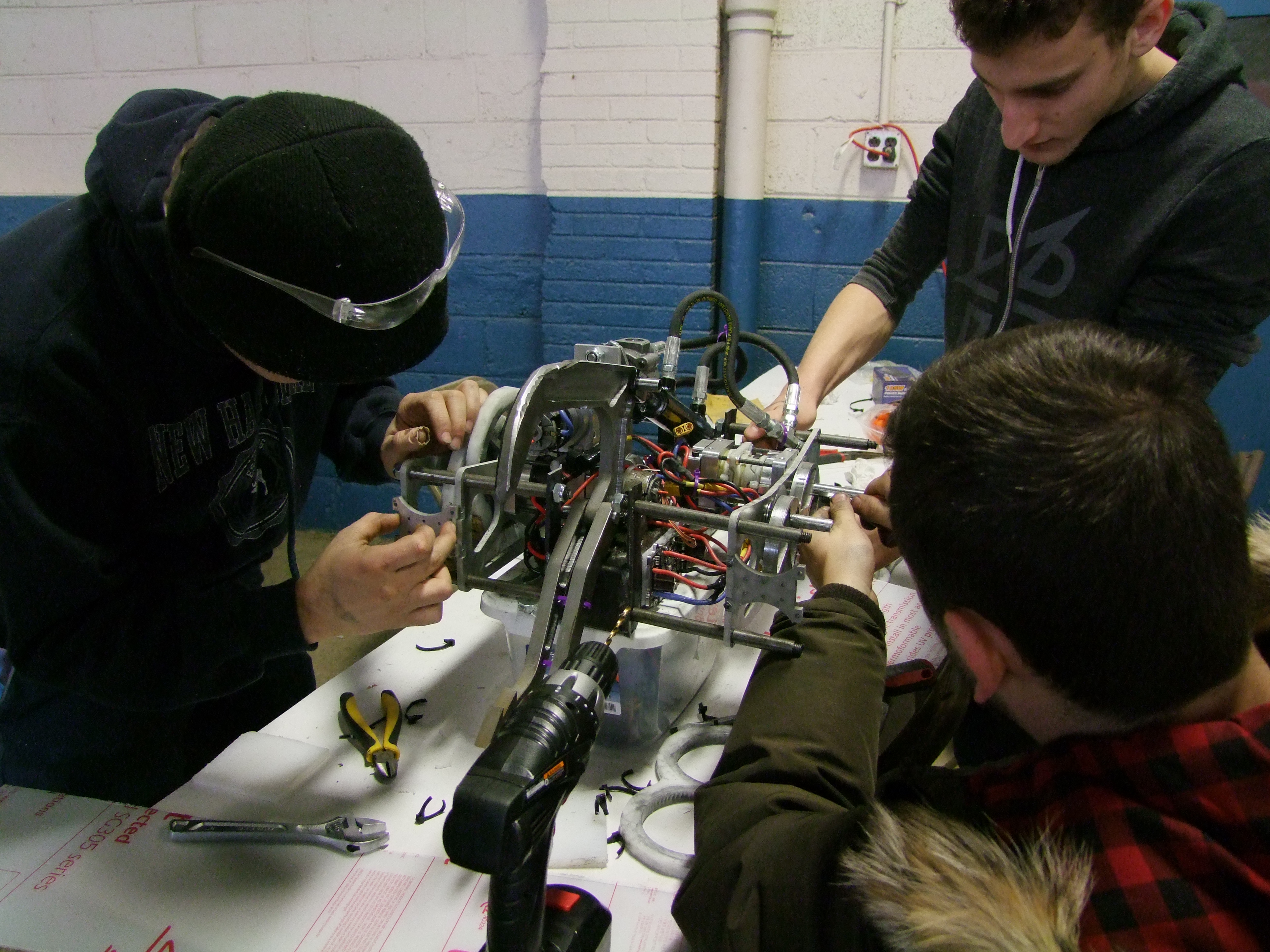

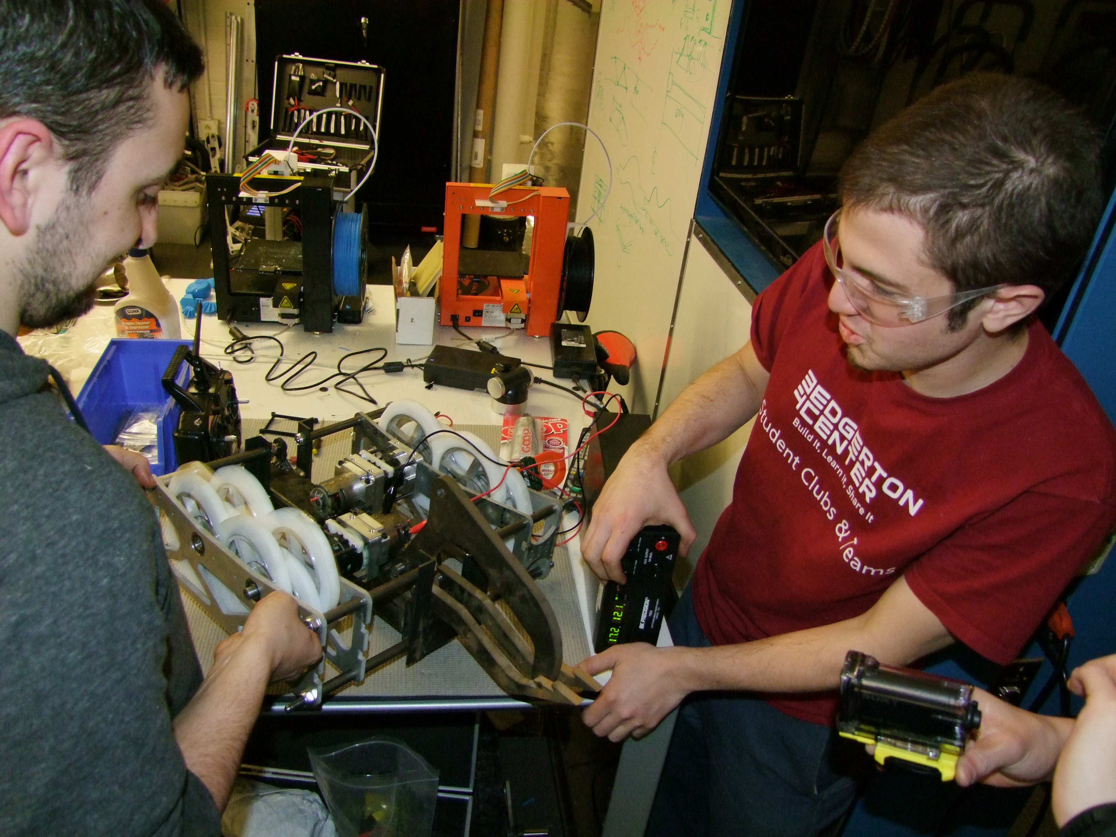
Shuffle-shields. With our non-existant extra mass leftover, thin polycarbonate was haistly added to shield the shuffle-drive. 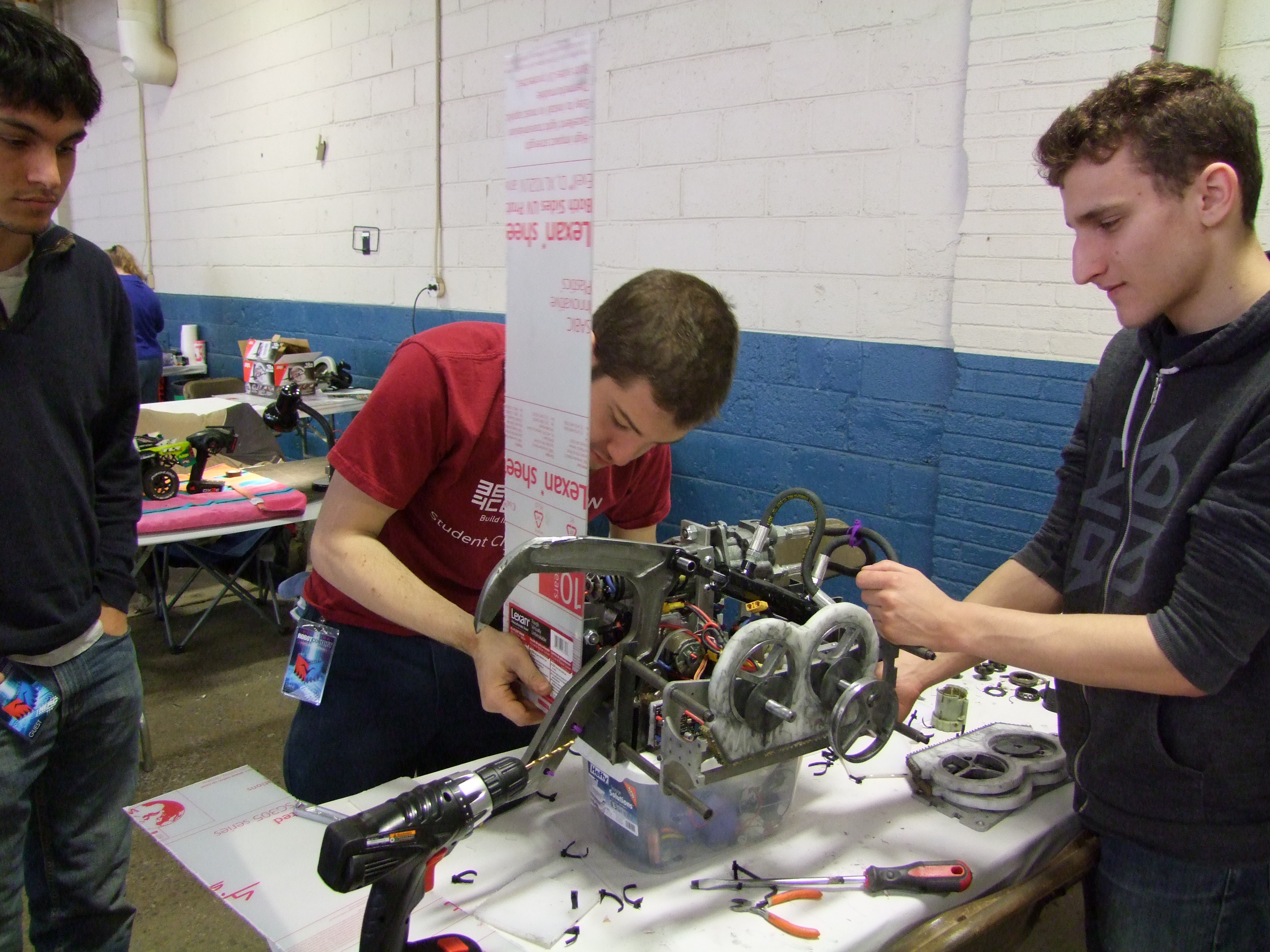
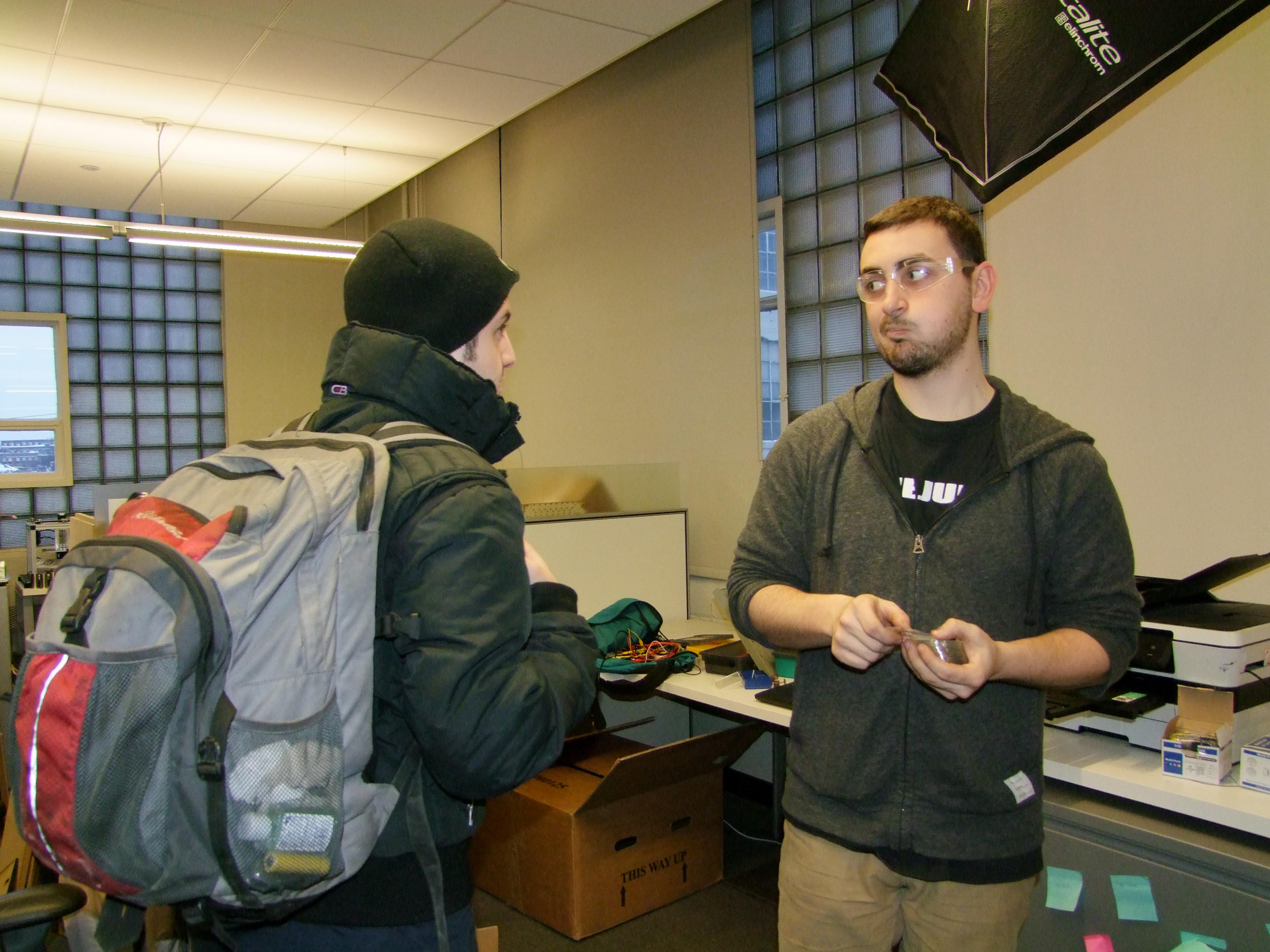
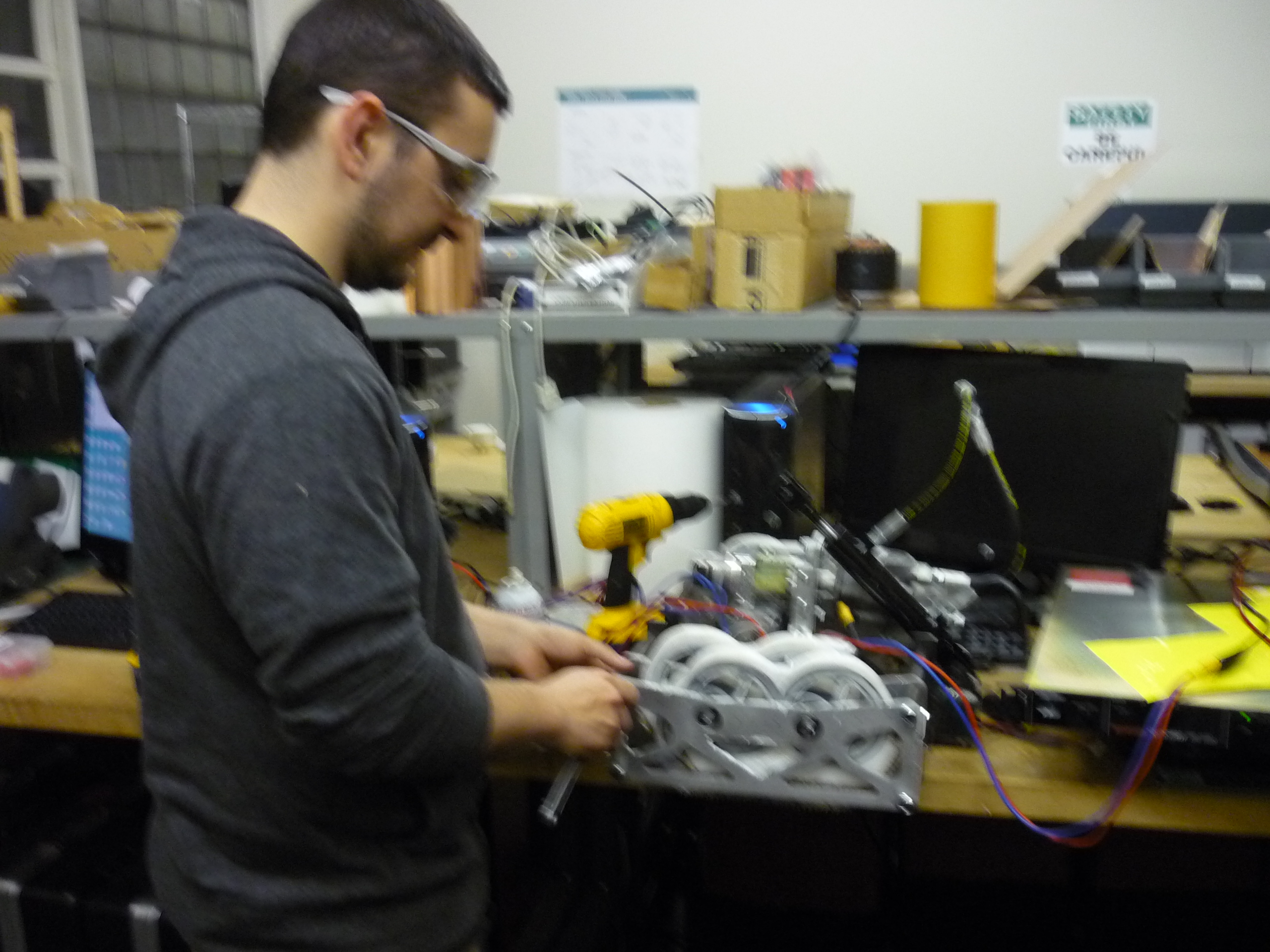
Safety First. A Xo armors the Bercu with old-timey safety glasses. Do you need goggles with side armor? you're in luck! mcmaster-carr pn xyxyxy. 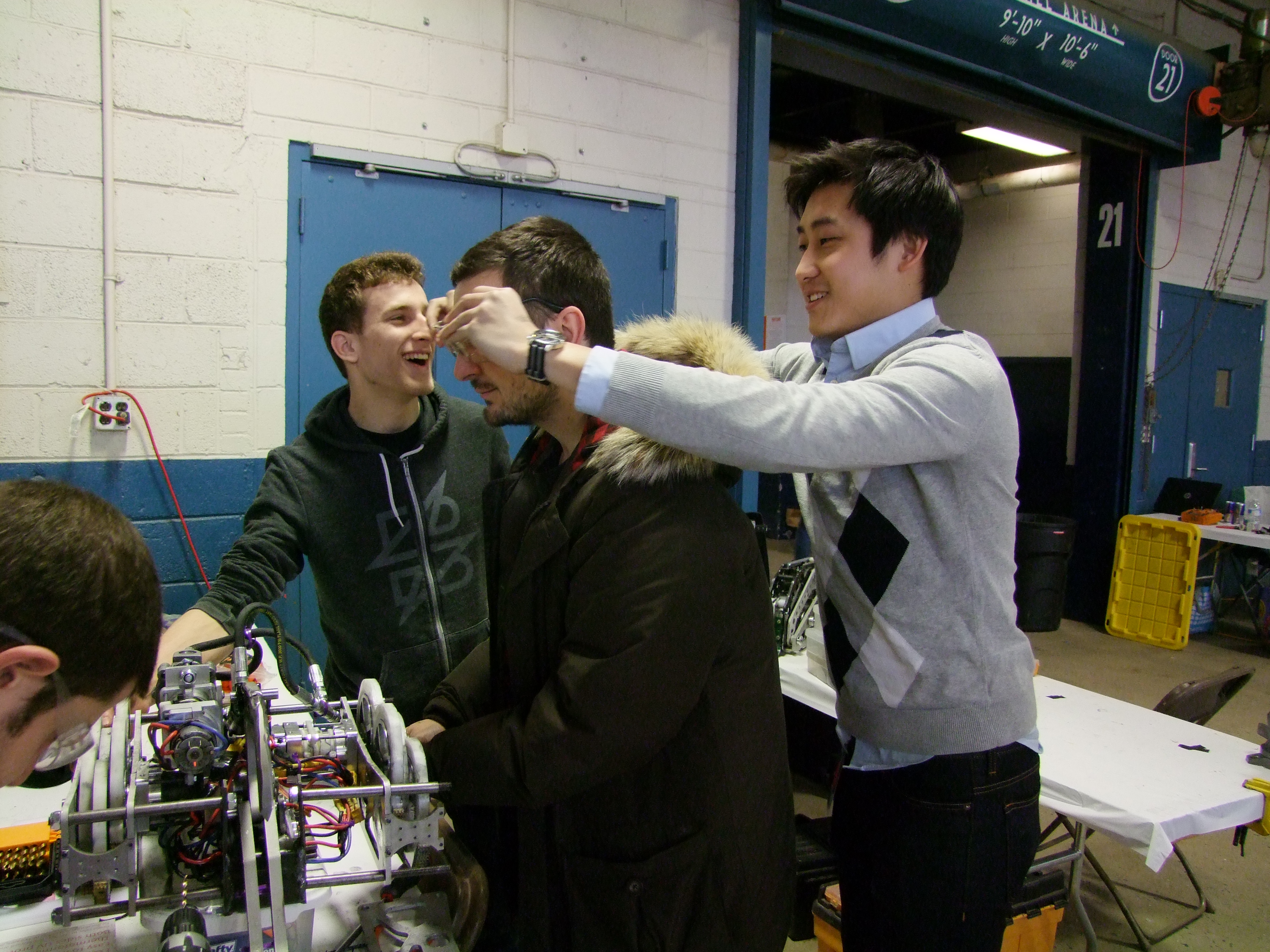

Holes and zipties ahoy. 
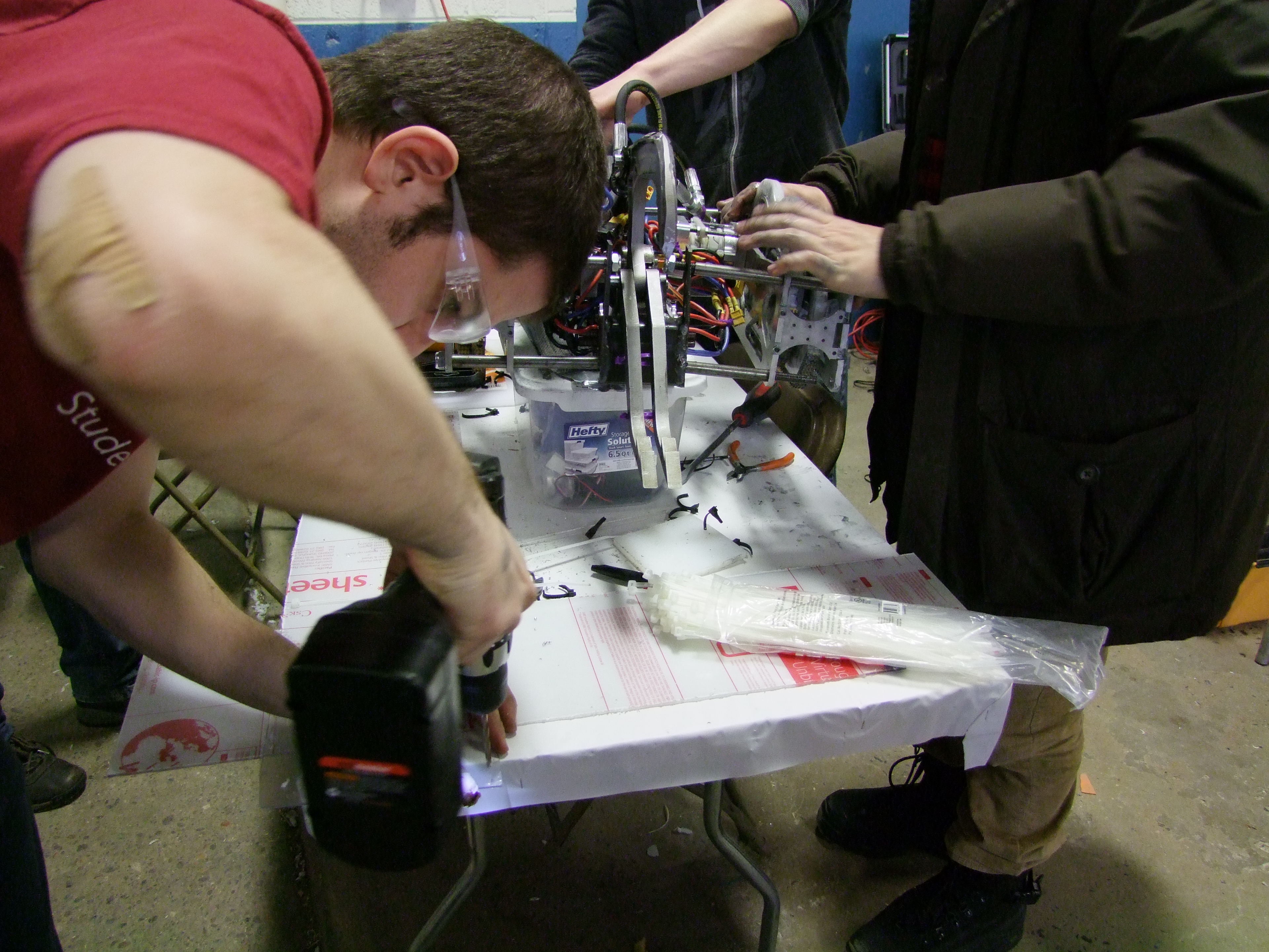
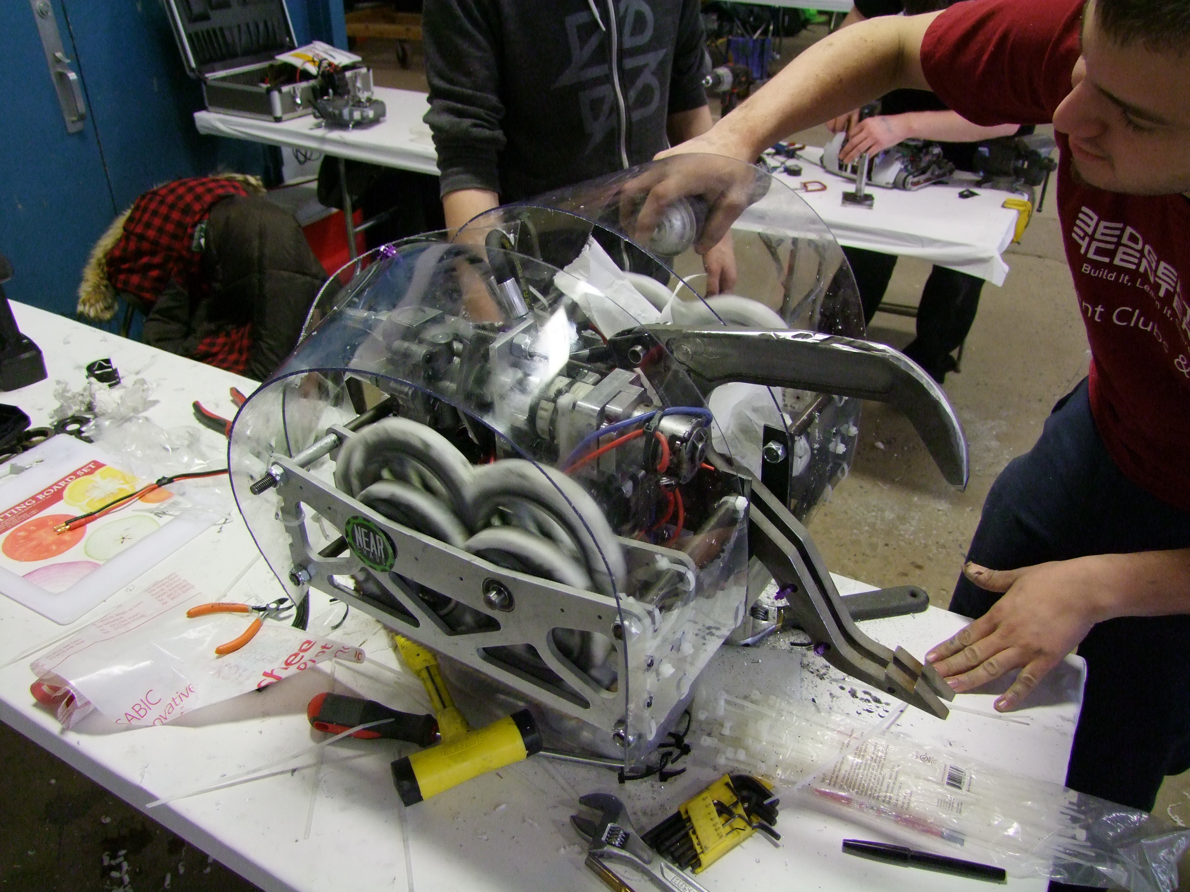

What kind of polycarbonate did we use? VIRTUALLY INDESTRUCTABLE BRAND POLYCARB 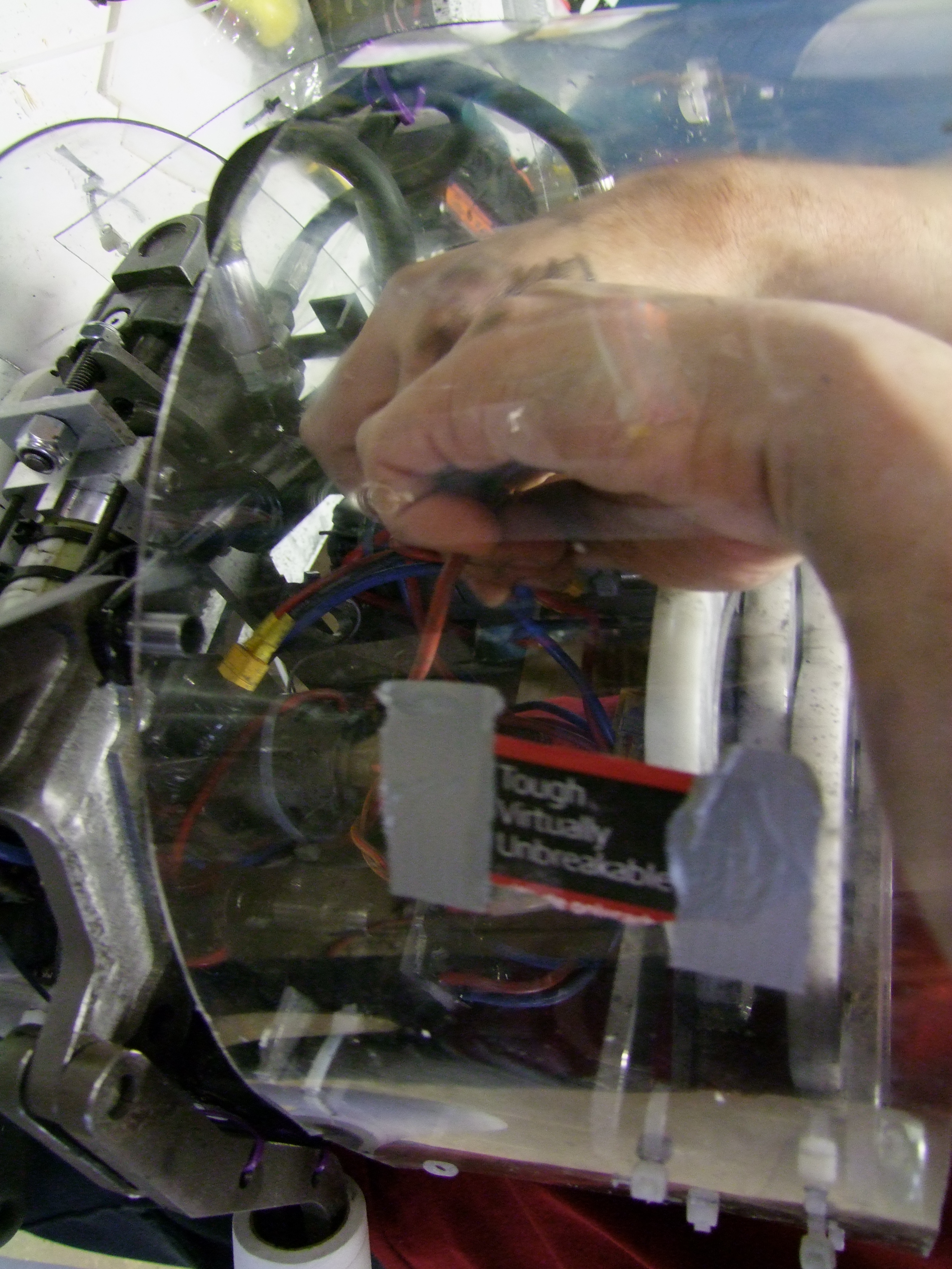
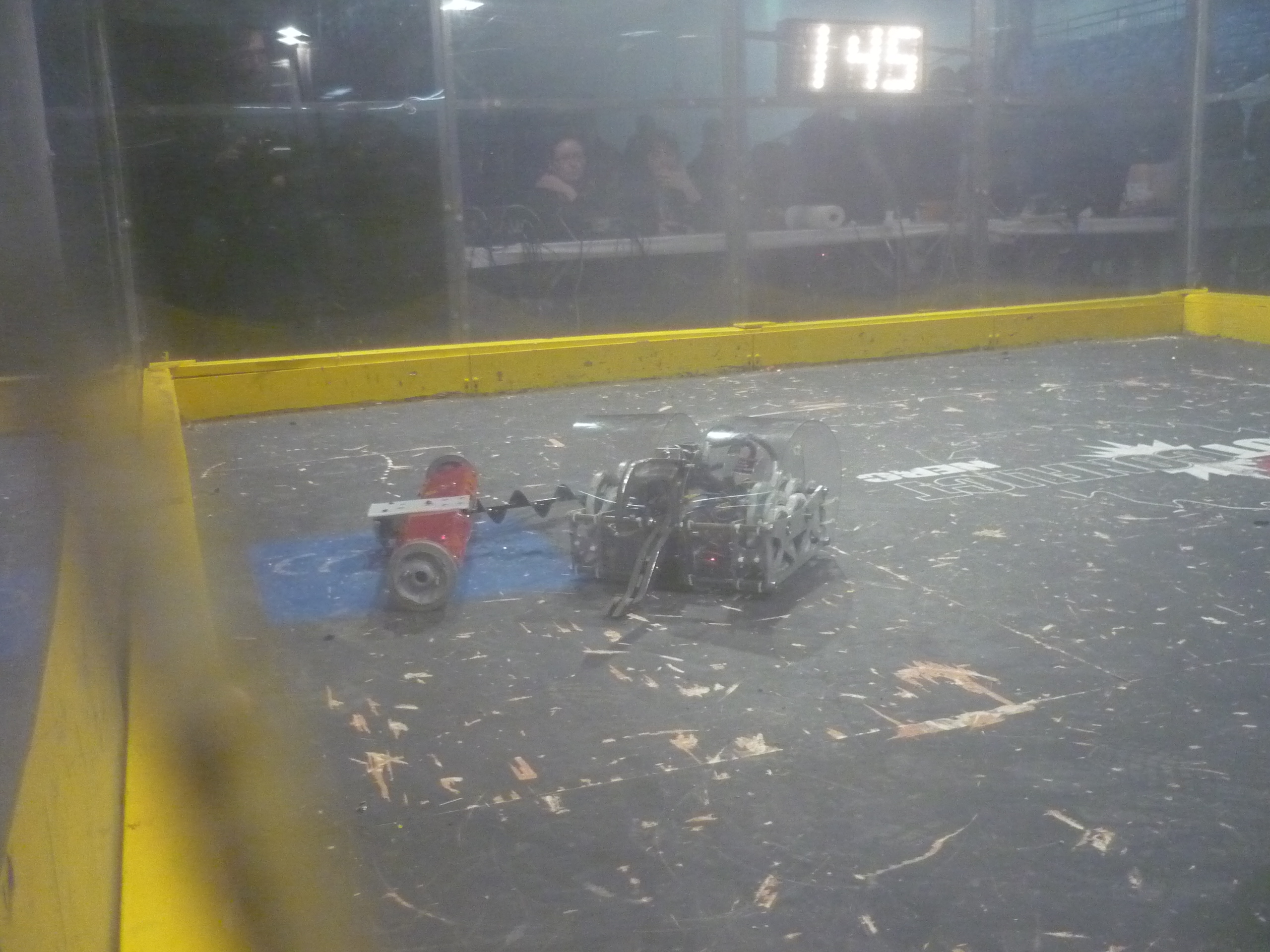
Into the arena. We faced a 'long screw' bot. 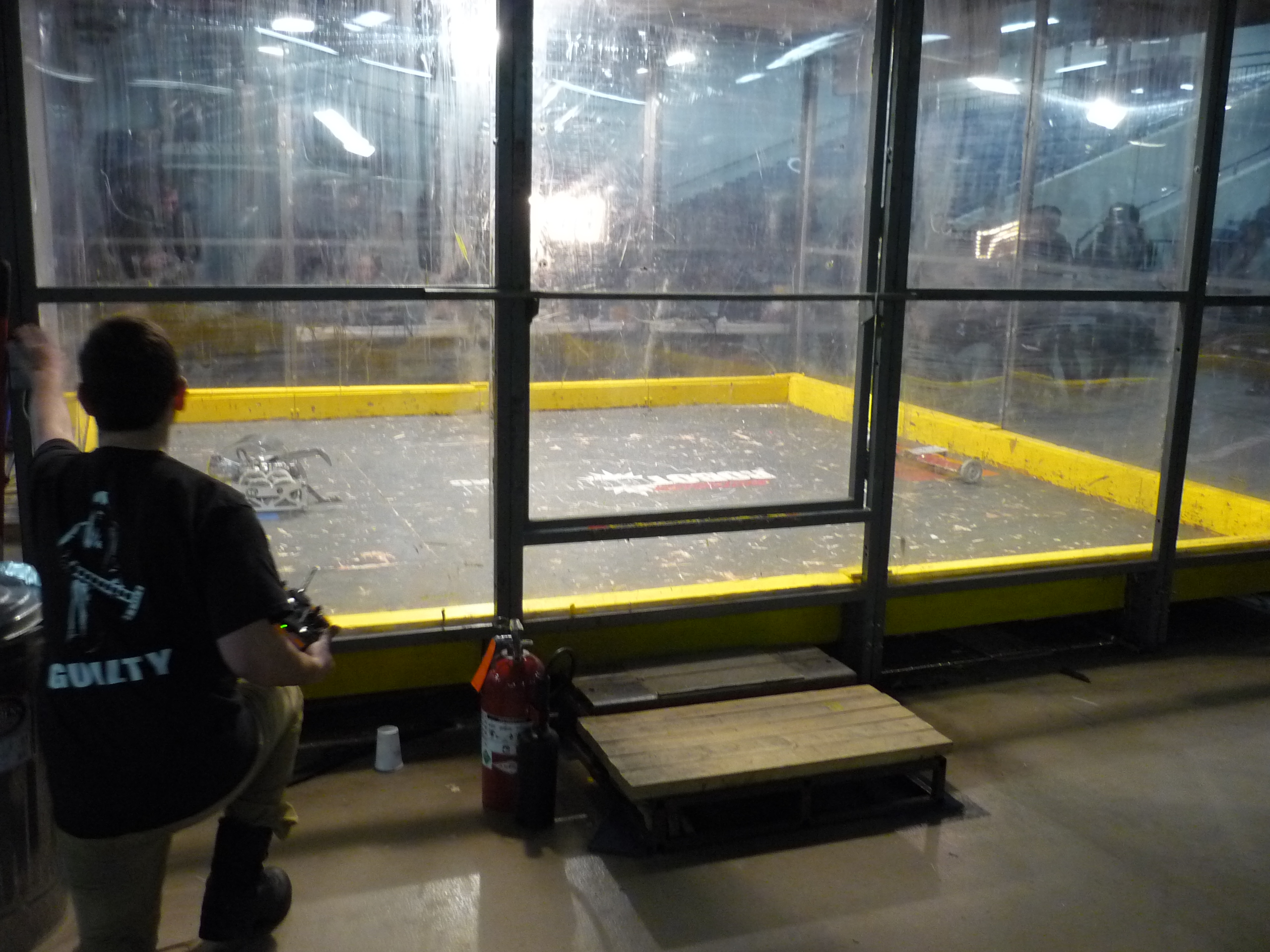
Concluding Remarks
What worked fairly well:
What could use improvement: Special thanks to Rob Reeve and A. Birkel If you have questions or comments, ask below or send over an email. Be careful, im not responsible for your welding tan or hydraulic sheen)
Have you noticed that there are no advertisements or ridiculous pop ups?
Want More?

|
Post your comments! |
|
Comment Box loading
|