Dane.Kouttron
[2.16.14] Atomic Bumble Prime [BATTLEBOTS]
| What?
This project documents the build of a 30lb featherweight battlebot for motorama 2014 in a relatively short timespan. 'Atomic Bumble Prime' was born as an upgrade from its older brother 'Atomic Bumble', my first foray into battlebots. Prime had some interesting design decisions, namely for the sake of time. Some worked better than expected, some, not so much. Build log follows below. |
 |
 |
| What? |
Demo Video | CAD | Shell Assembly | Base Plate Build | Propulsion | Bill of Materials | War Wounds | Image Directory |
| What
is it that I actually want to accomplish here? |
Upgrades from the original
atomic-bumble:
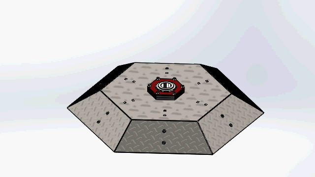
Robot render from photoview360 (solidworks)
|
 |
| Background |
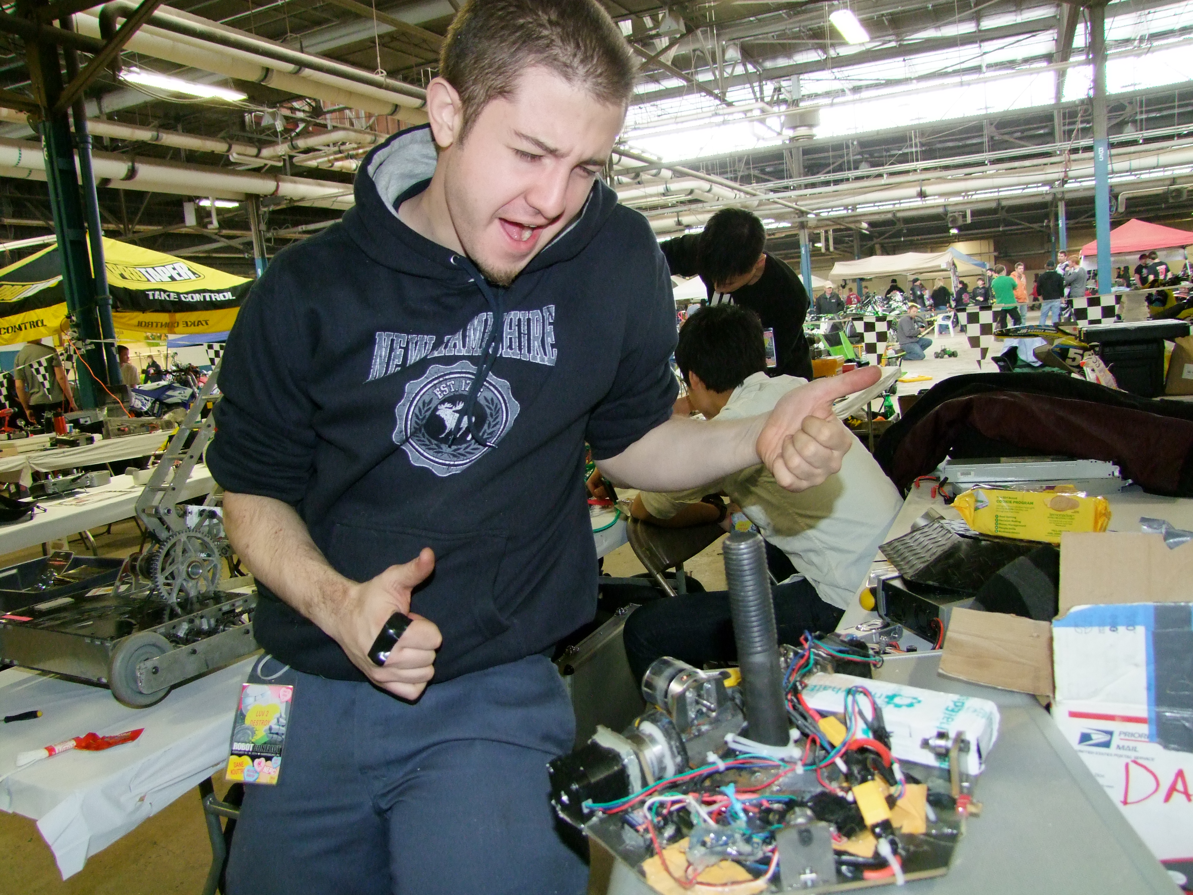
| 'Prime's build was put on hold to complete a rather extensive oral and written qualification exam, which, ended roughly 5 days before motorama 2014. It happened again! A week before competition and the robot has yet to be born! with some very late evenings, an overnight mcmaster-order and a hail-mary, last minute bearing distrubitor, the robot came into existence. I was fortunate enough to head to competition with the ever-fantastic Charles G, Bercu, Jamo and Cynthia, who supplied some fantastic last-minute ideas as well as incredible abilities to weld/bond things using miscellaneous tools in unknown states. |
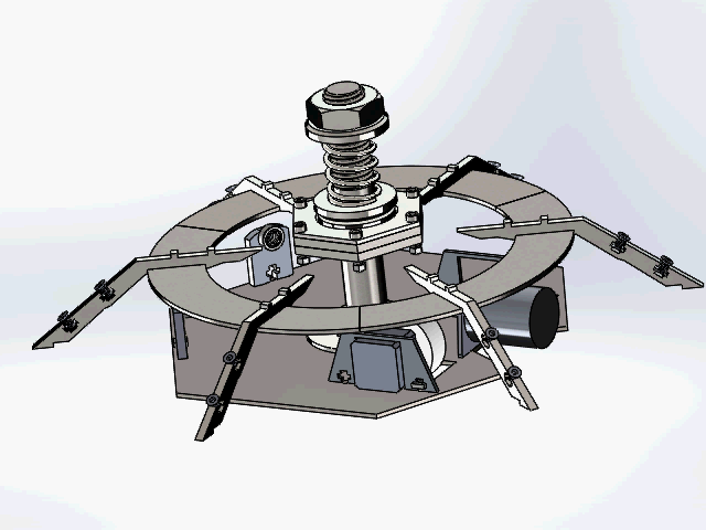
The haistly thrown together CAD model


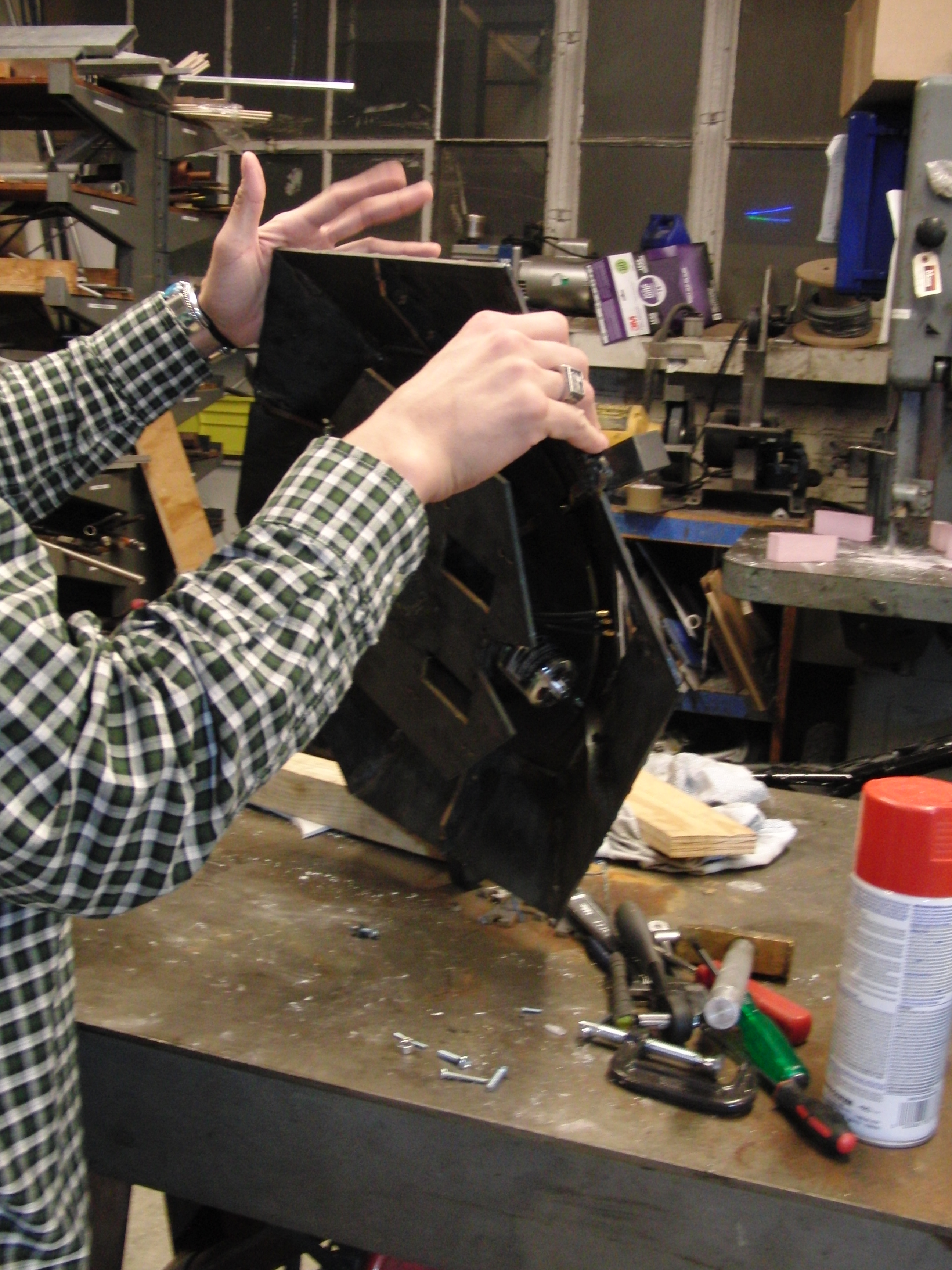
Shell Build
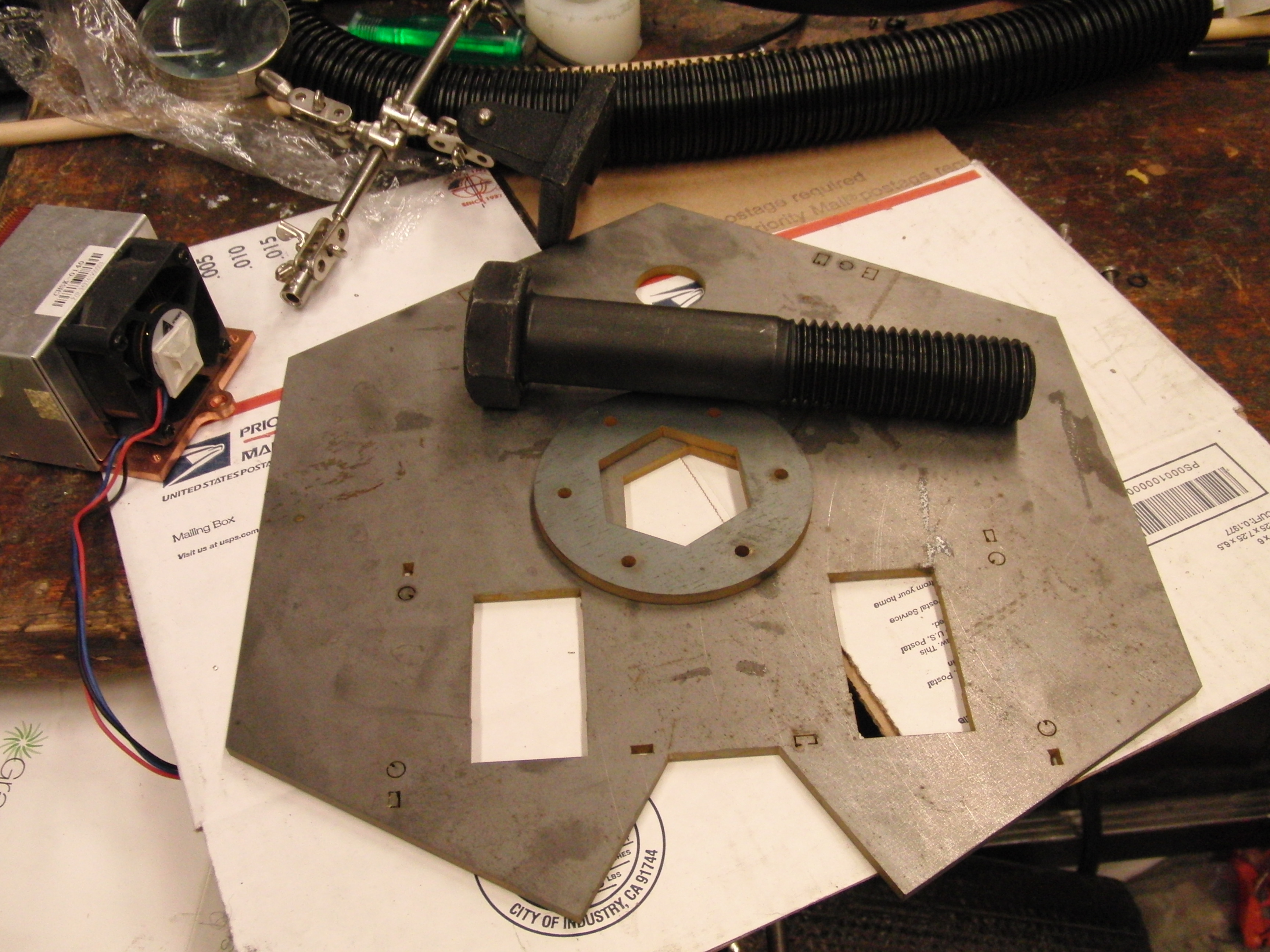
| Waterjets and welders ahoy | ||
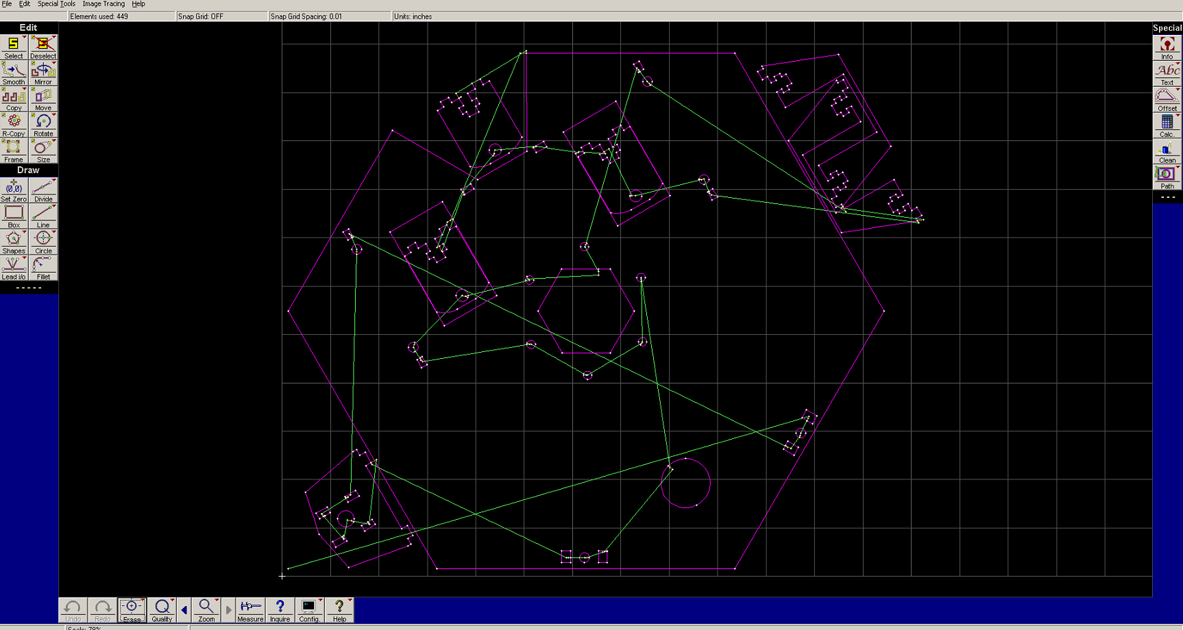
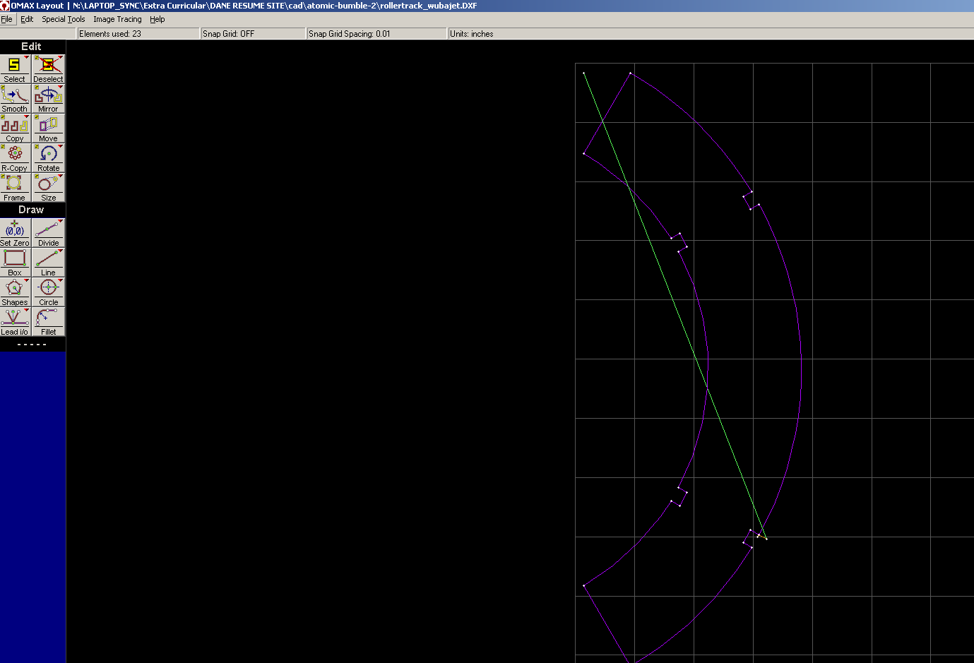
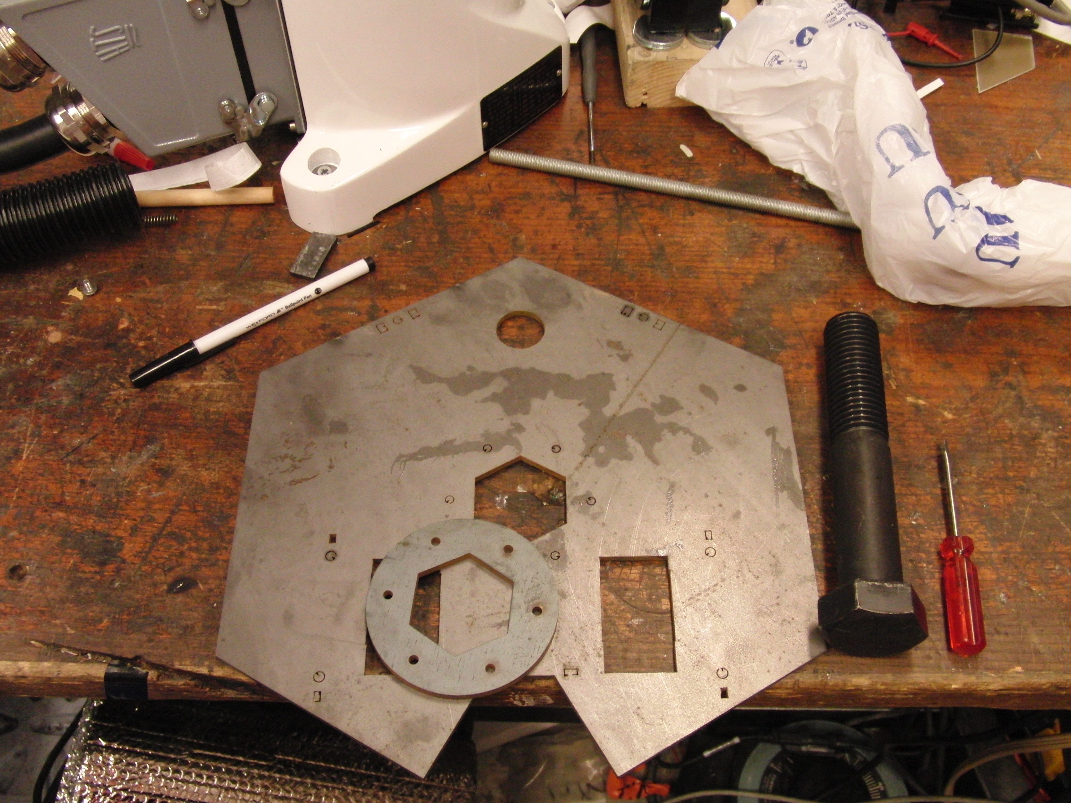
| OMAX I was fortunate to have shop access to the wonderful waterjet over at MIT's hobbyshop. Its an early generation cantilever waterjet, but makes mincemeat of 1/4" steel plate. To save time I pre-computed trajectories for the bot cuts and was able to complete all the cuts (shell skirt plates, top plate, inner braces, bearing holsters, over three 1 hour job timeslots. While 3 hours seems like a lot there is a bit of setup involved and |
 |
 |
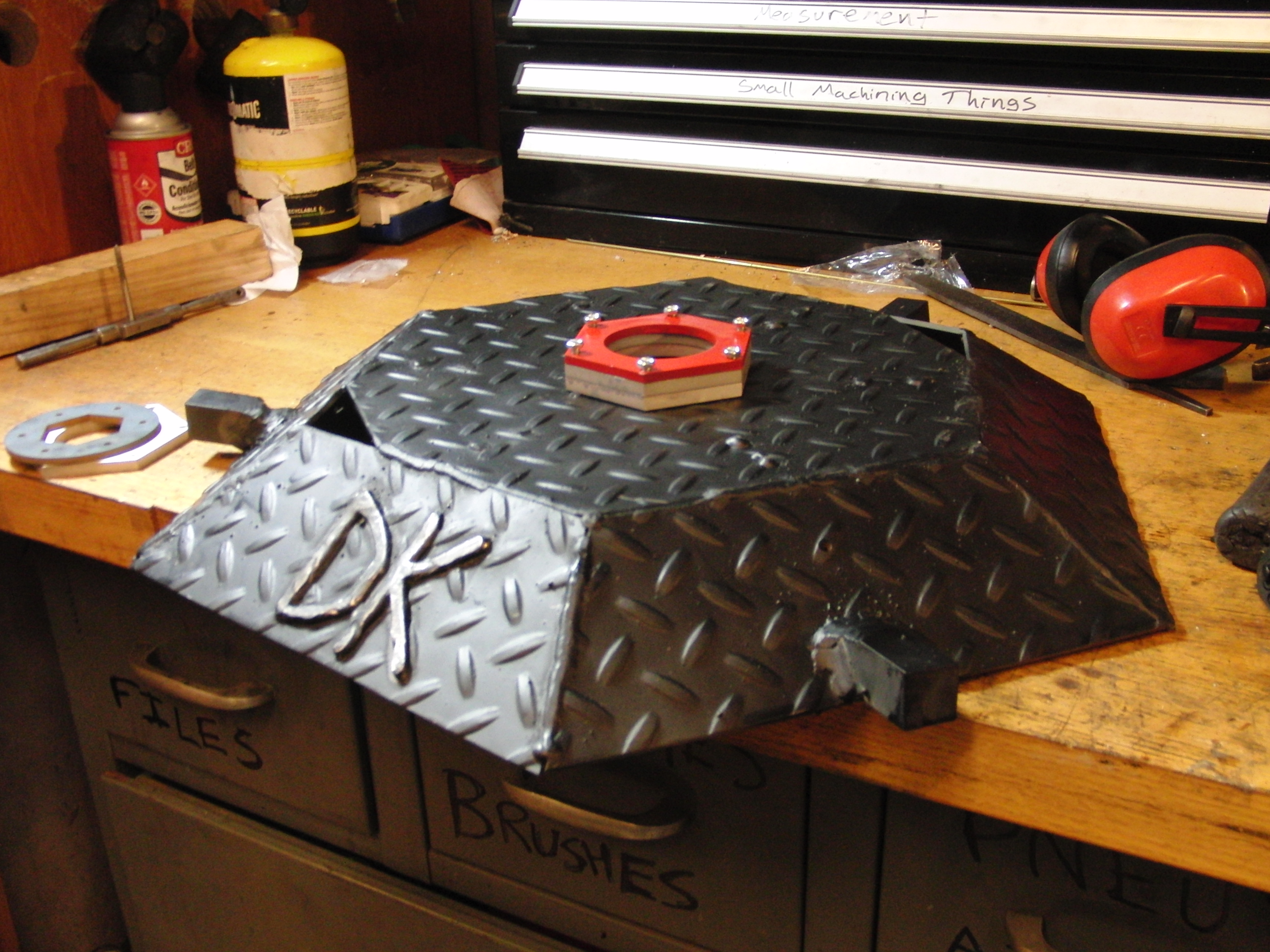
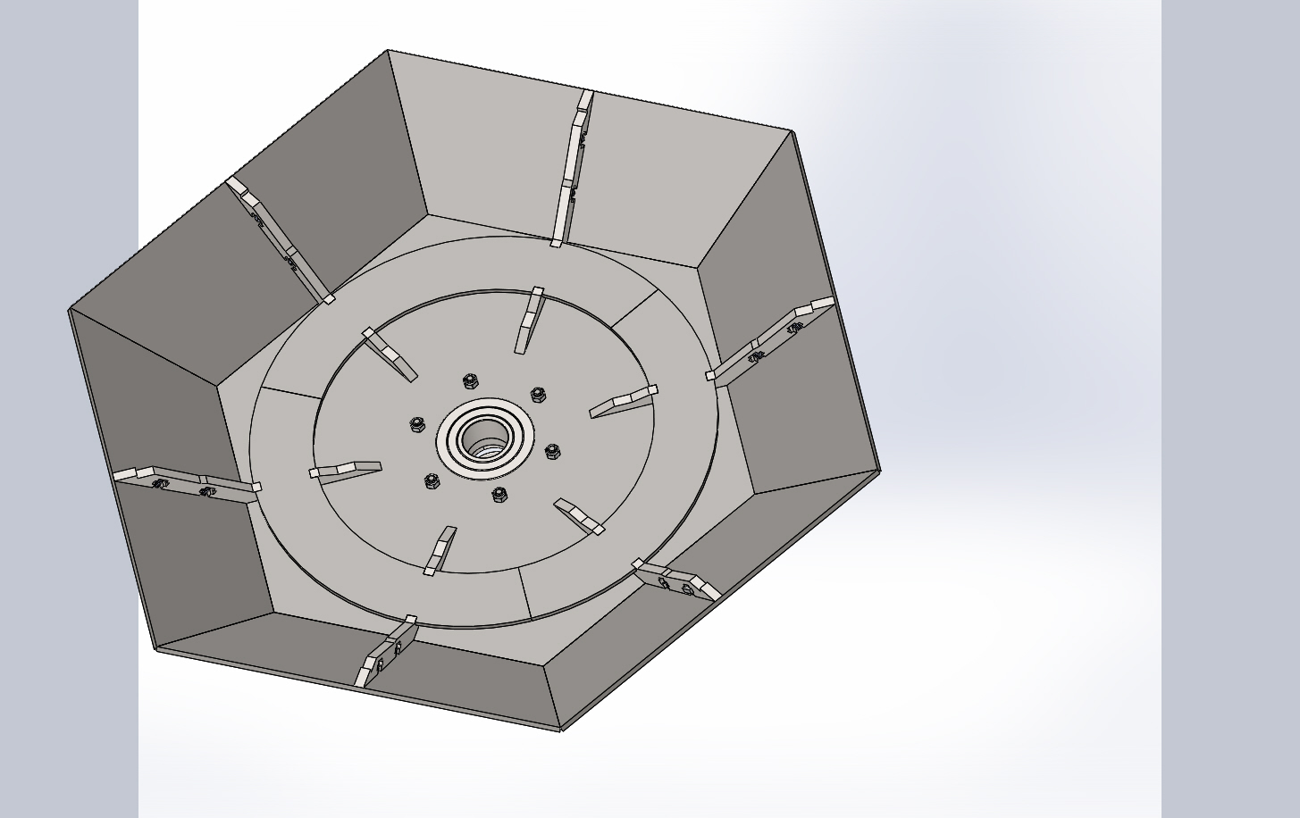
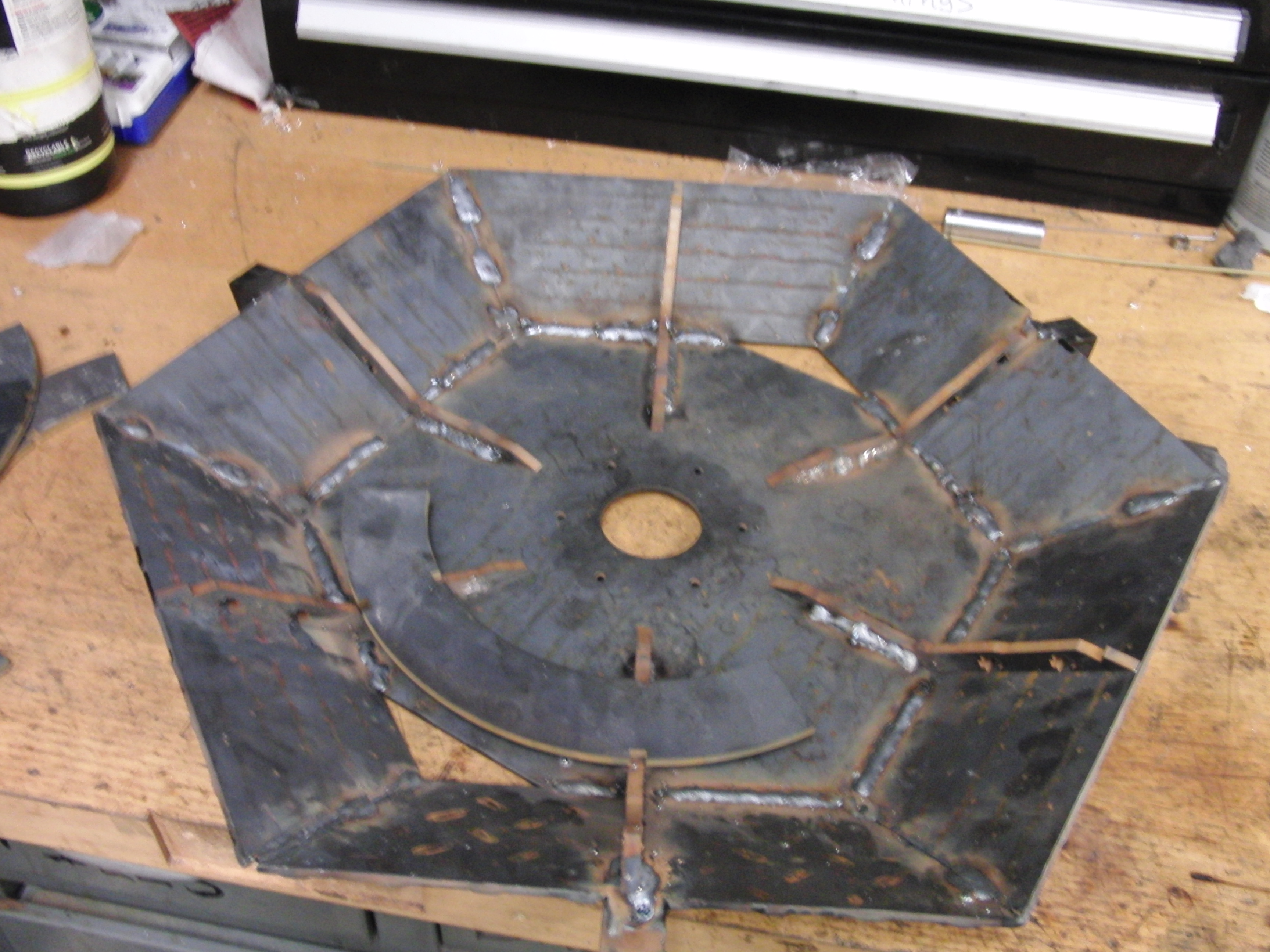
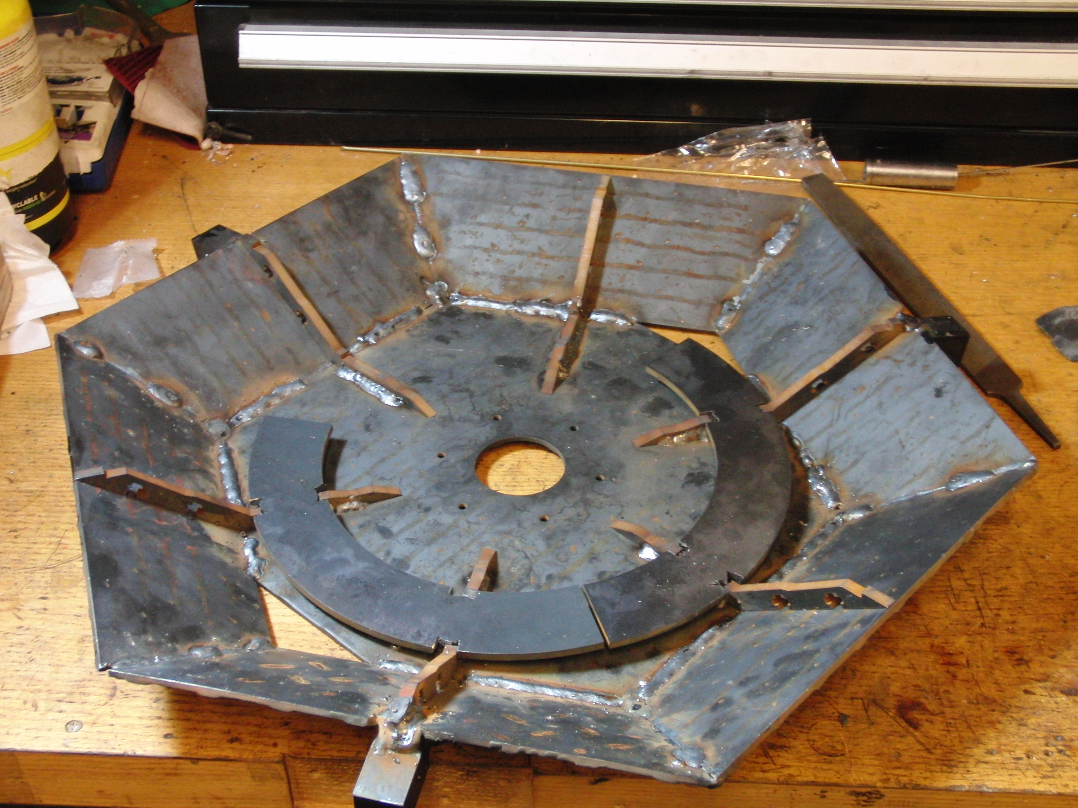
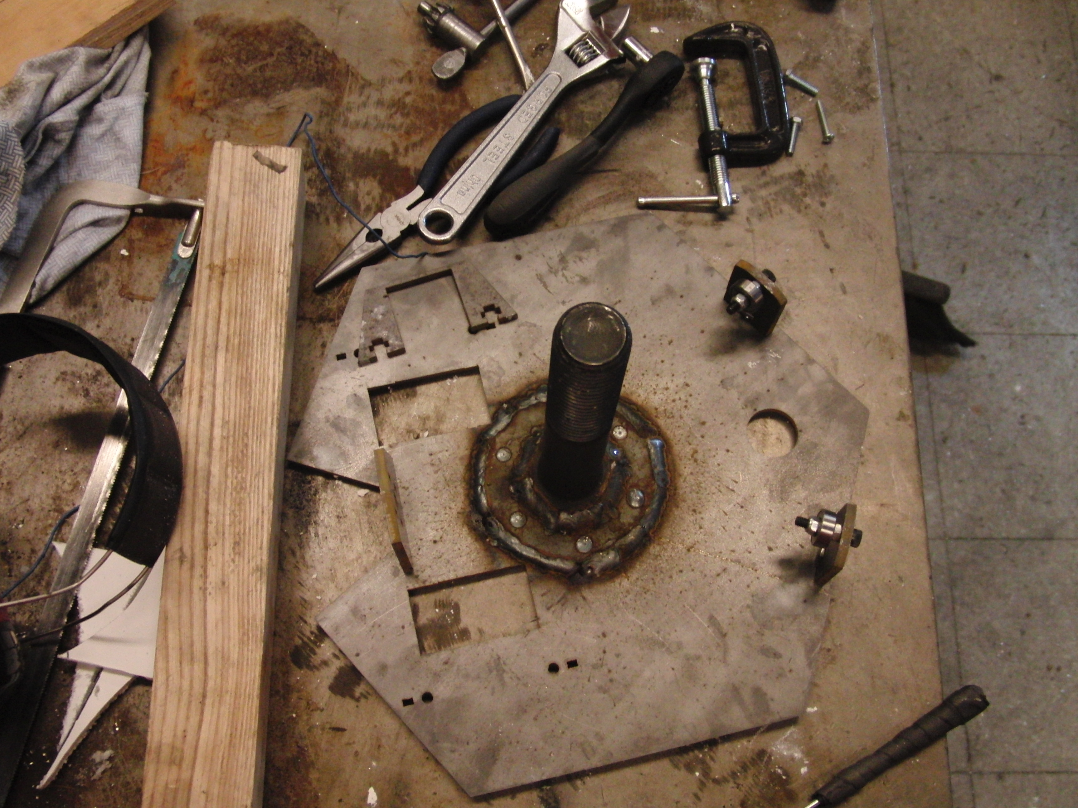
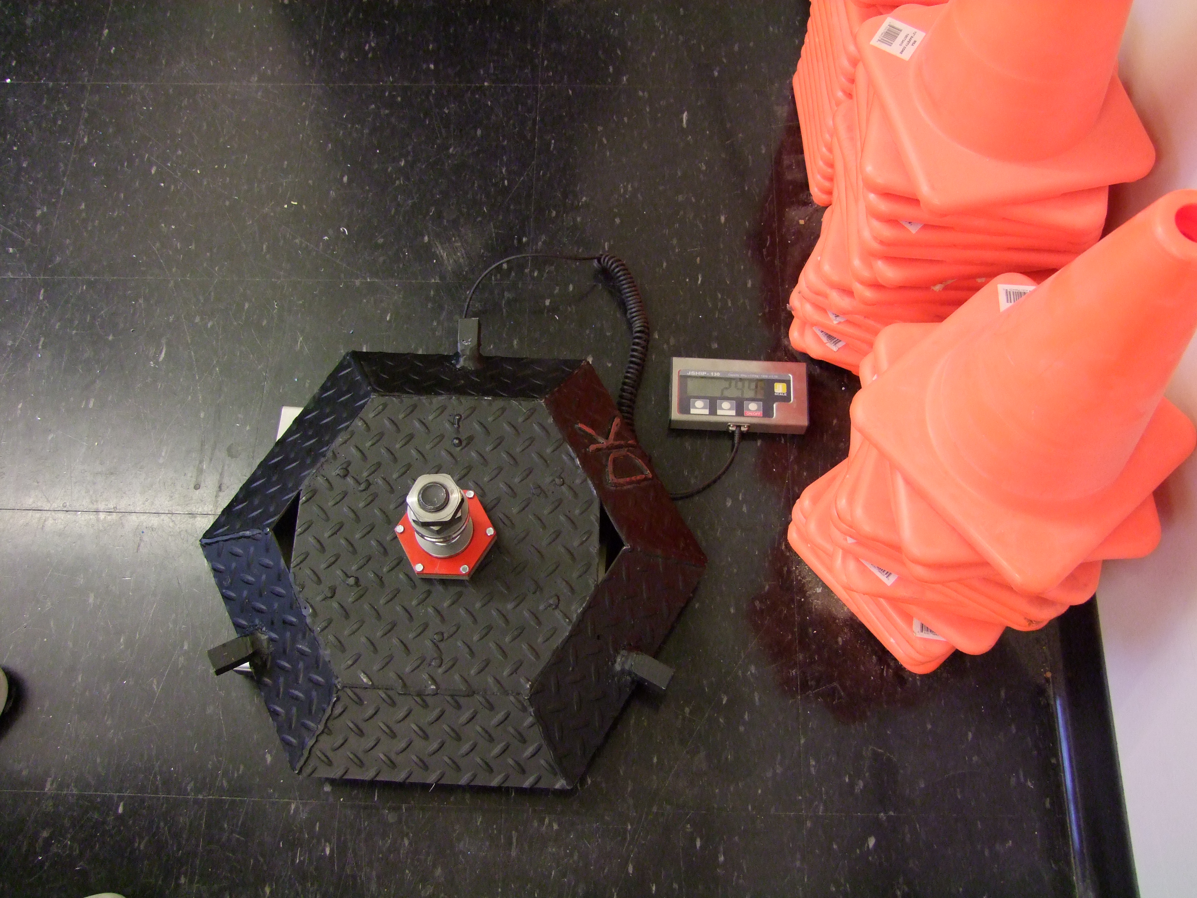
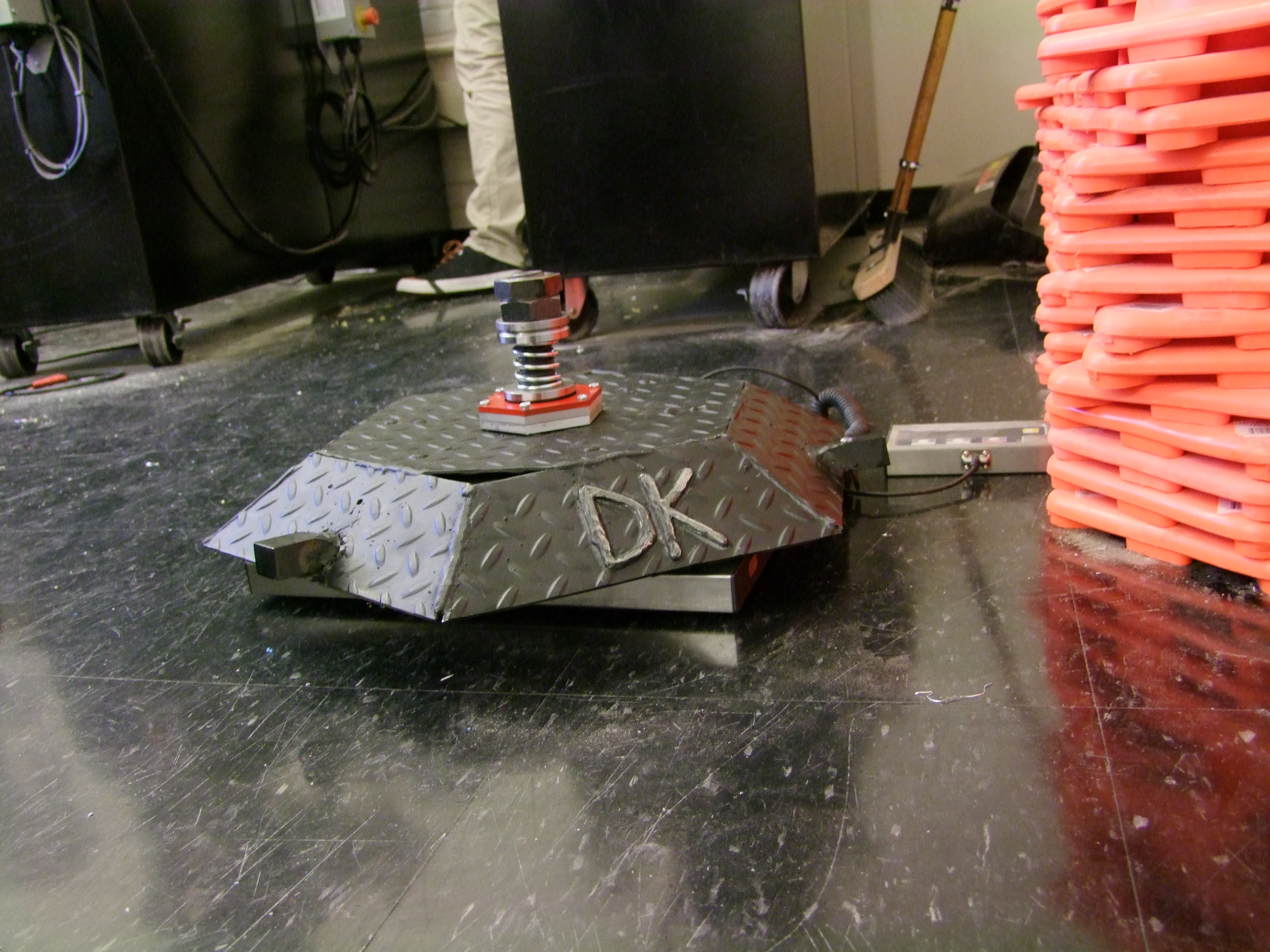
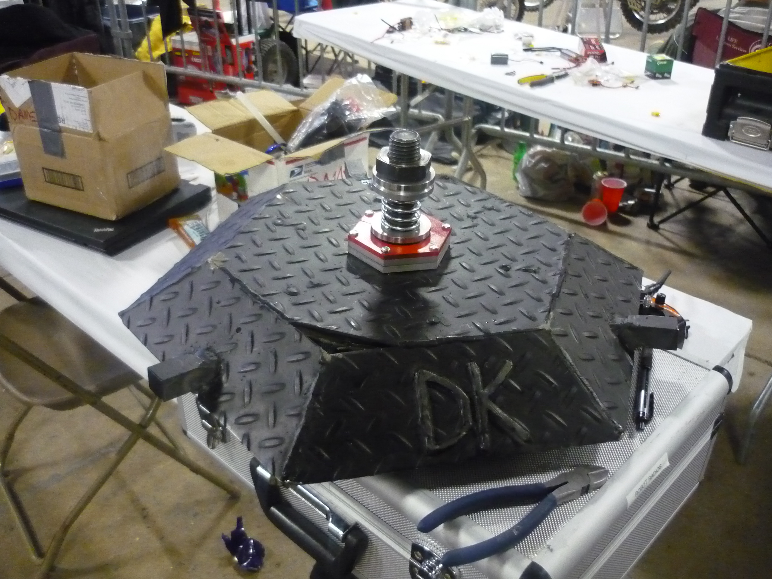
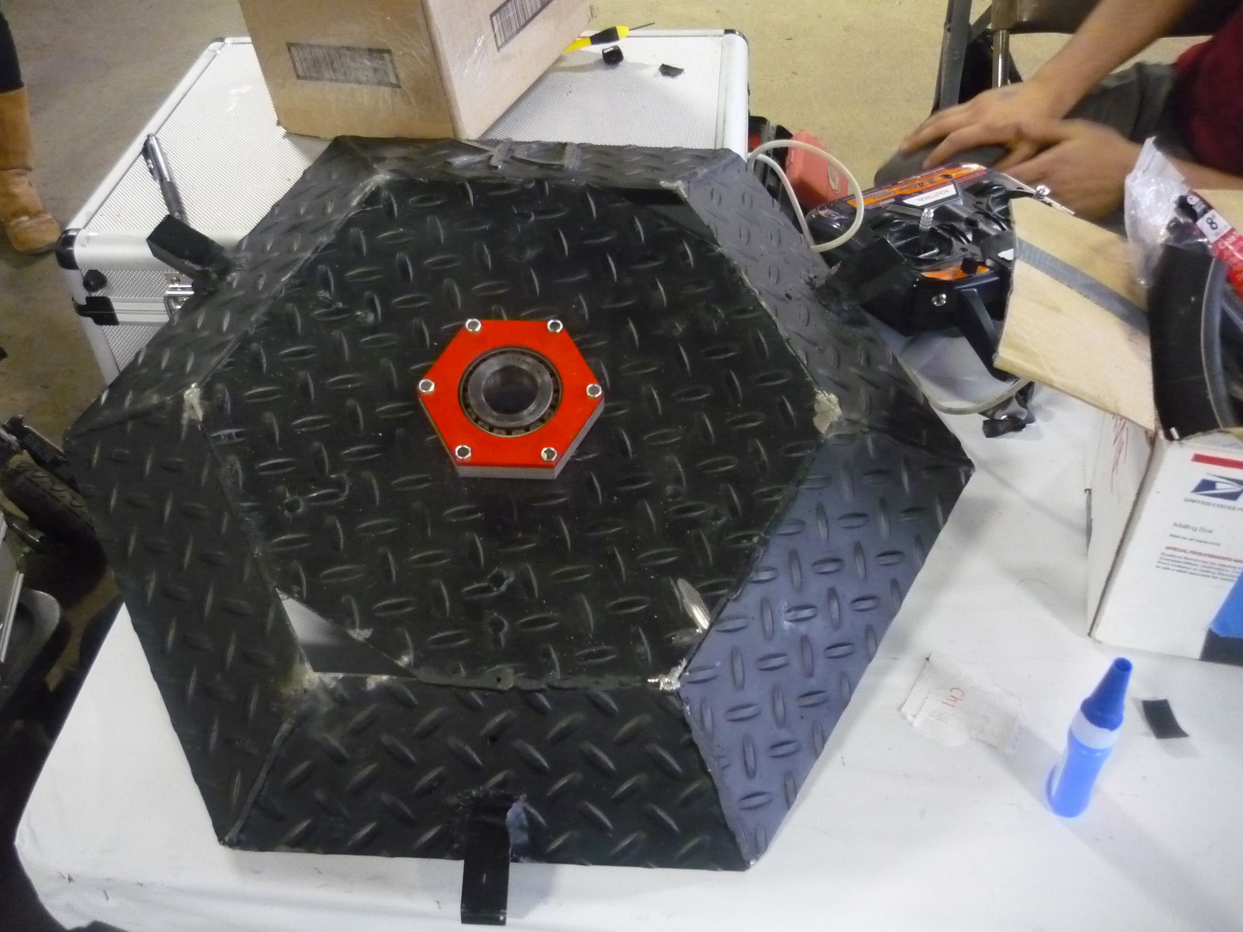
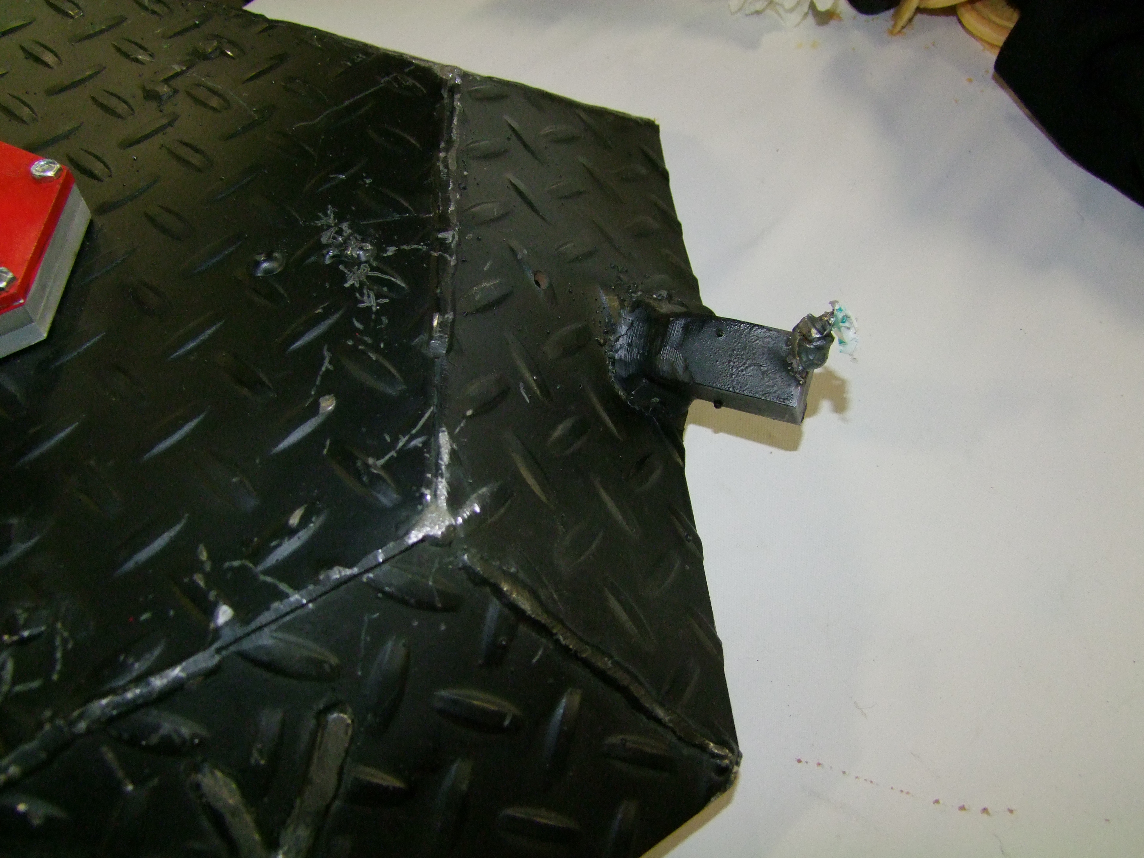
| The inside of the exoskeleton The shell has six braces mounted in slotted holes on the top-plate and mounted to the skirt plates via T-nut bolts Welds were used to bond the two together. Initially i had wanted to leave the skirt plates bolted in place, for balancing, then weld, but due to time-constraints, welding came first. The plates were mig-welded together and to the support skeleton. Copious amounts of MIG welds pulled everything together. Ivan Vanko would be proud. |
|
 |
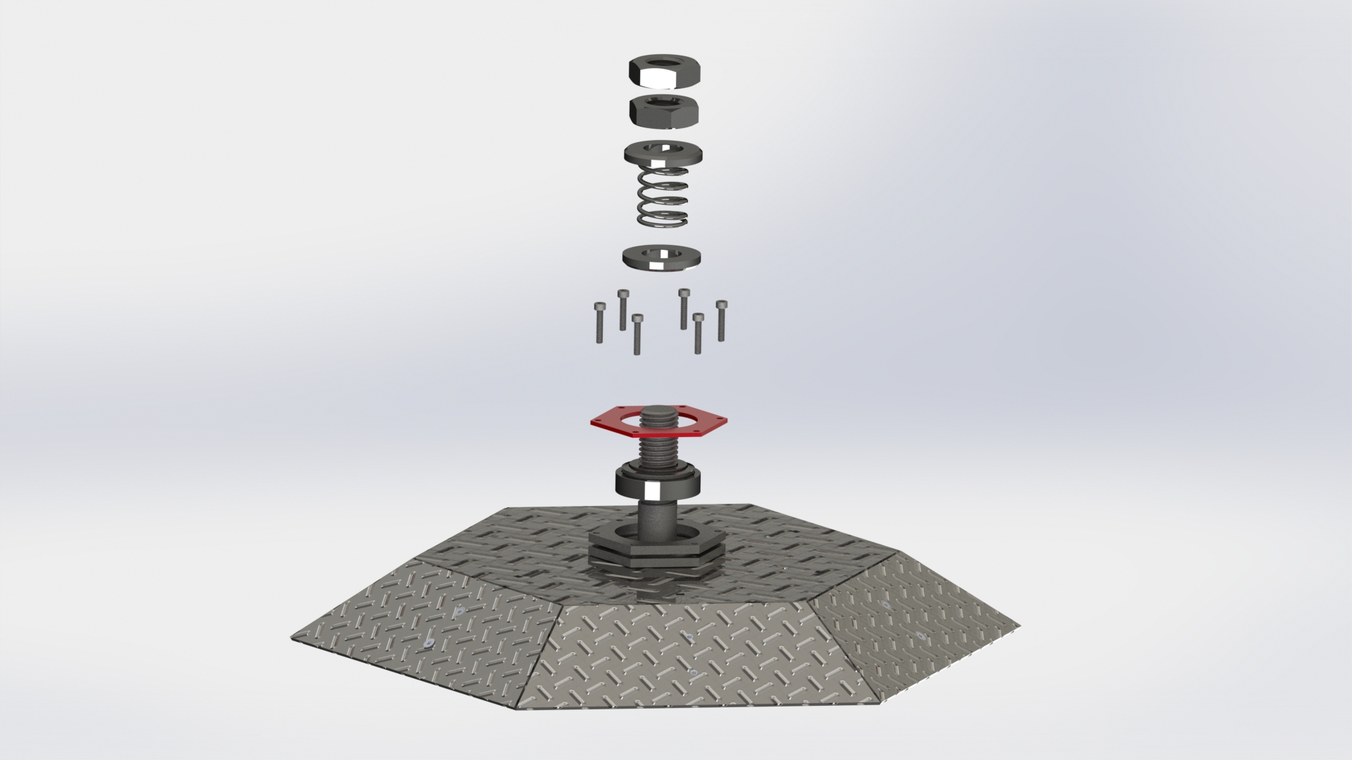
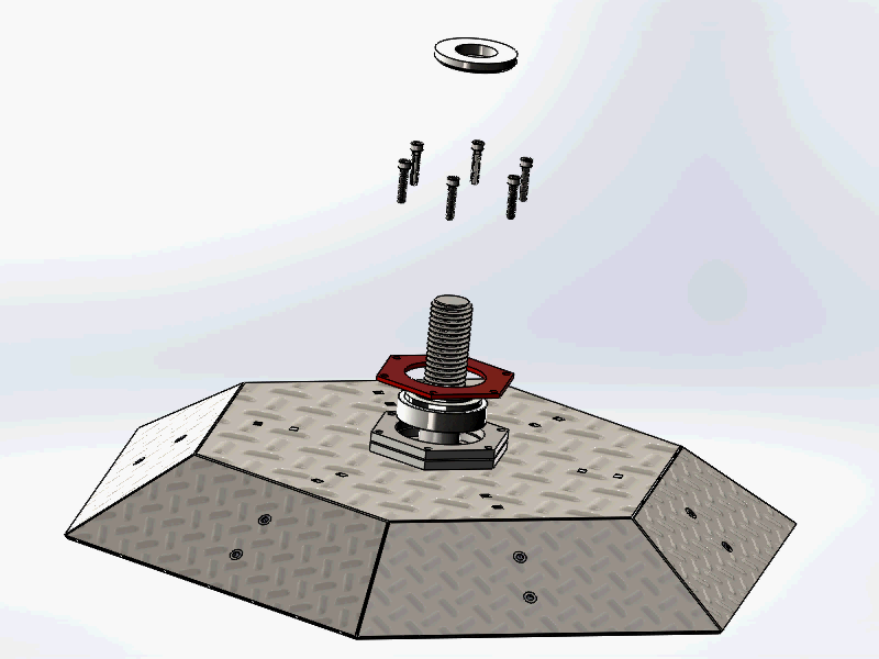
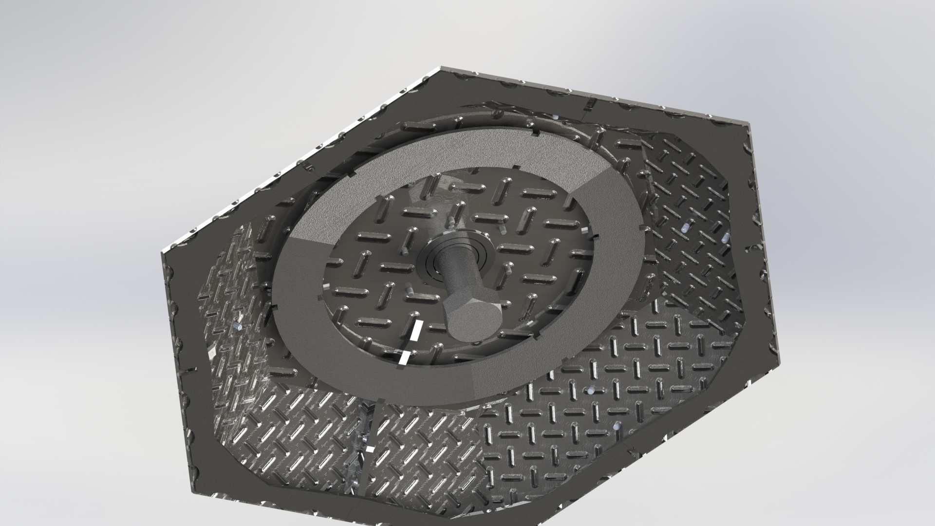
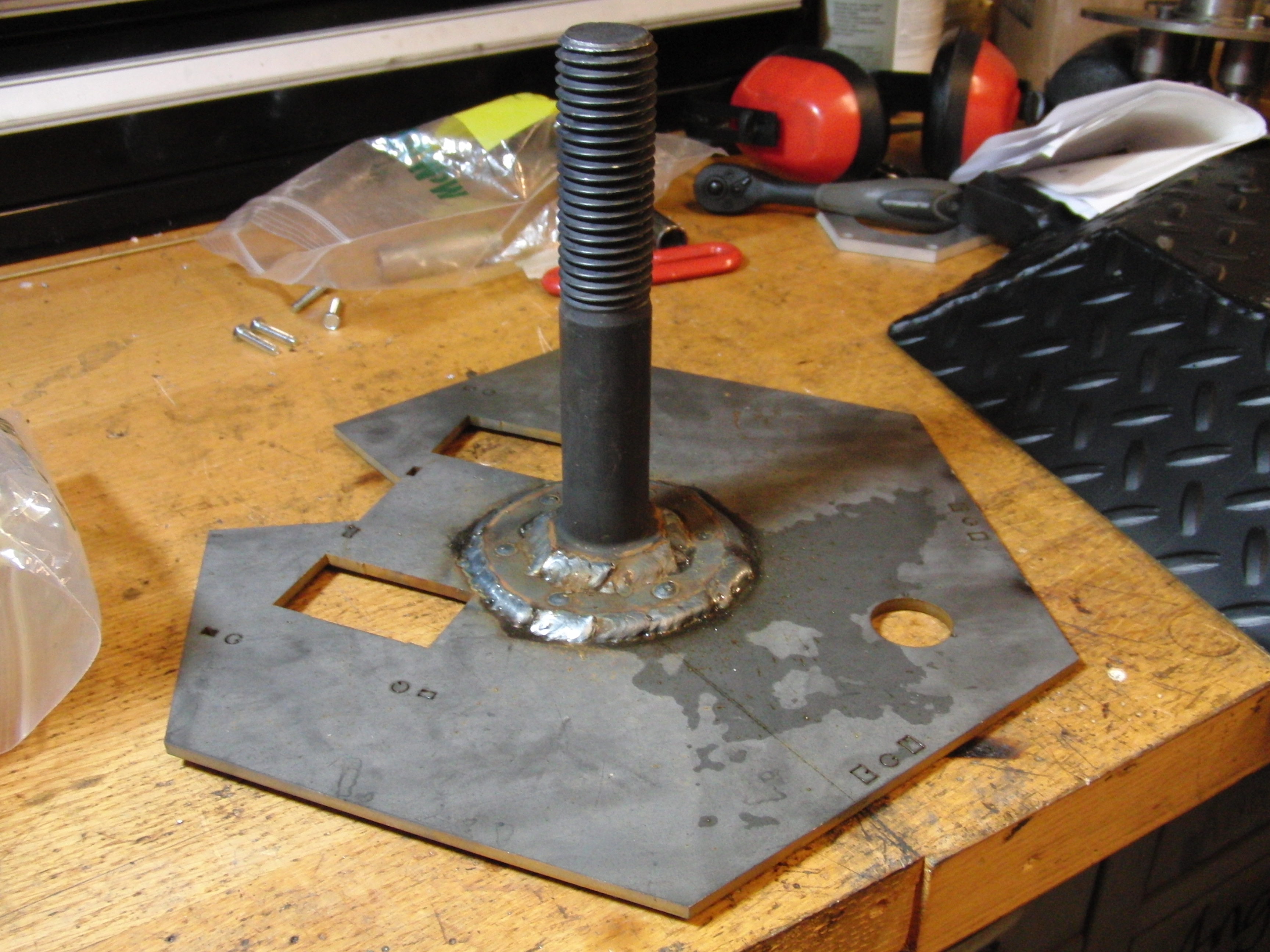
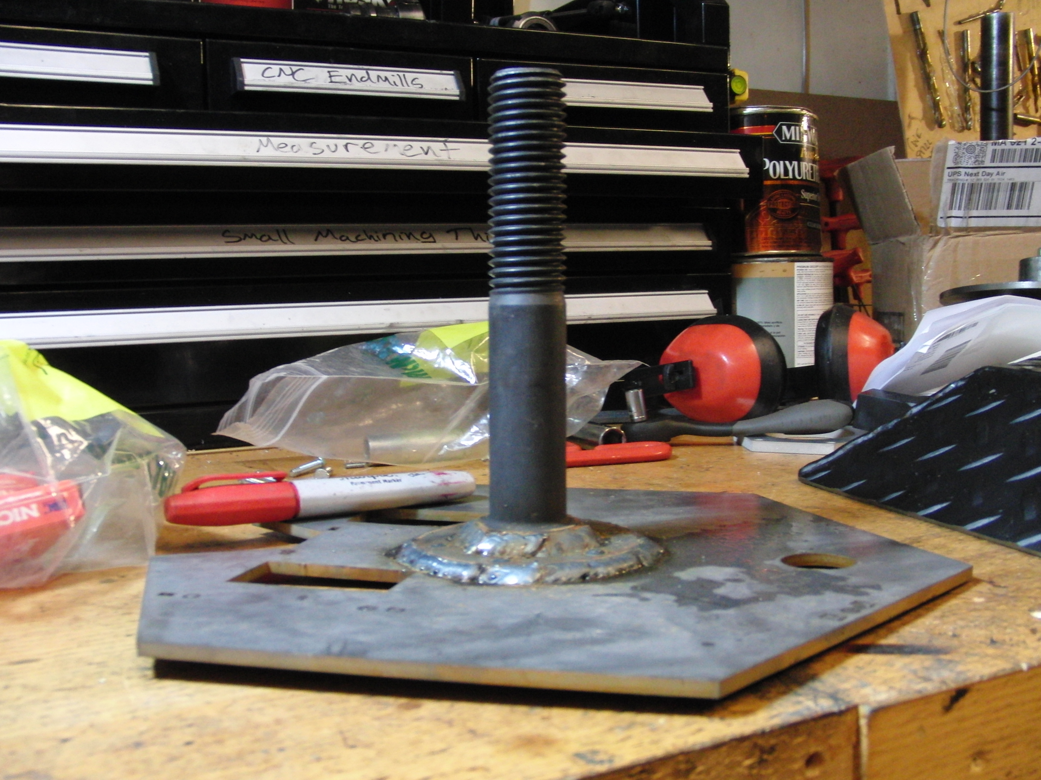
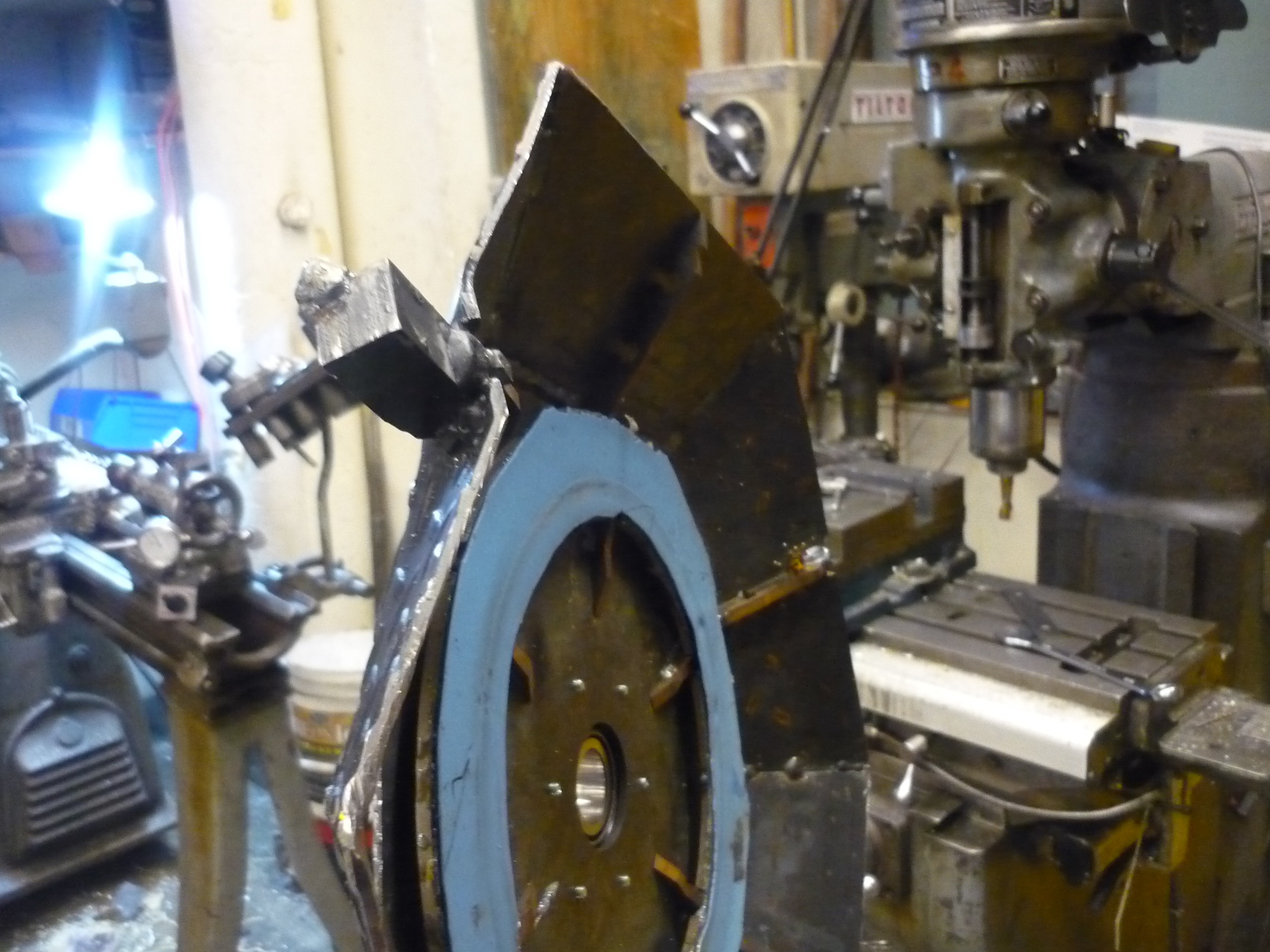
| The racetrack The skeletal supports contained two mounting points for the racetrack assembly. These mounting points align the racetrack. Before welding, there were some minor hacksaw-cuts required to get everything in as snug-ly as possible. |
 |
 |
| Placement
and welds After a final test-fit, the racetrack was haistly tack welded in place. The welds were intended to not breech the surface of the track as this would create stress spots for the rollers and bearings. |
 |
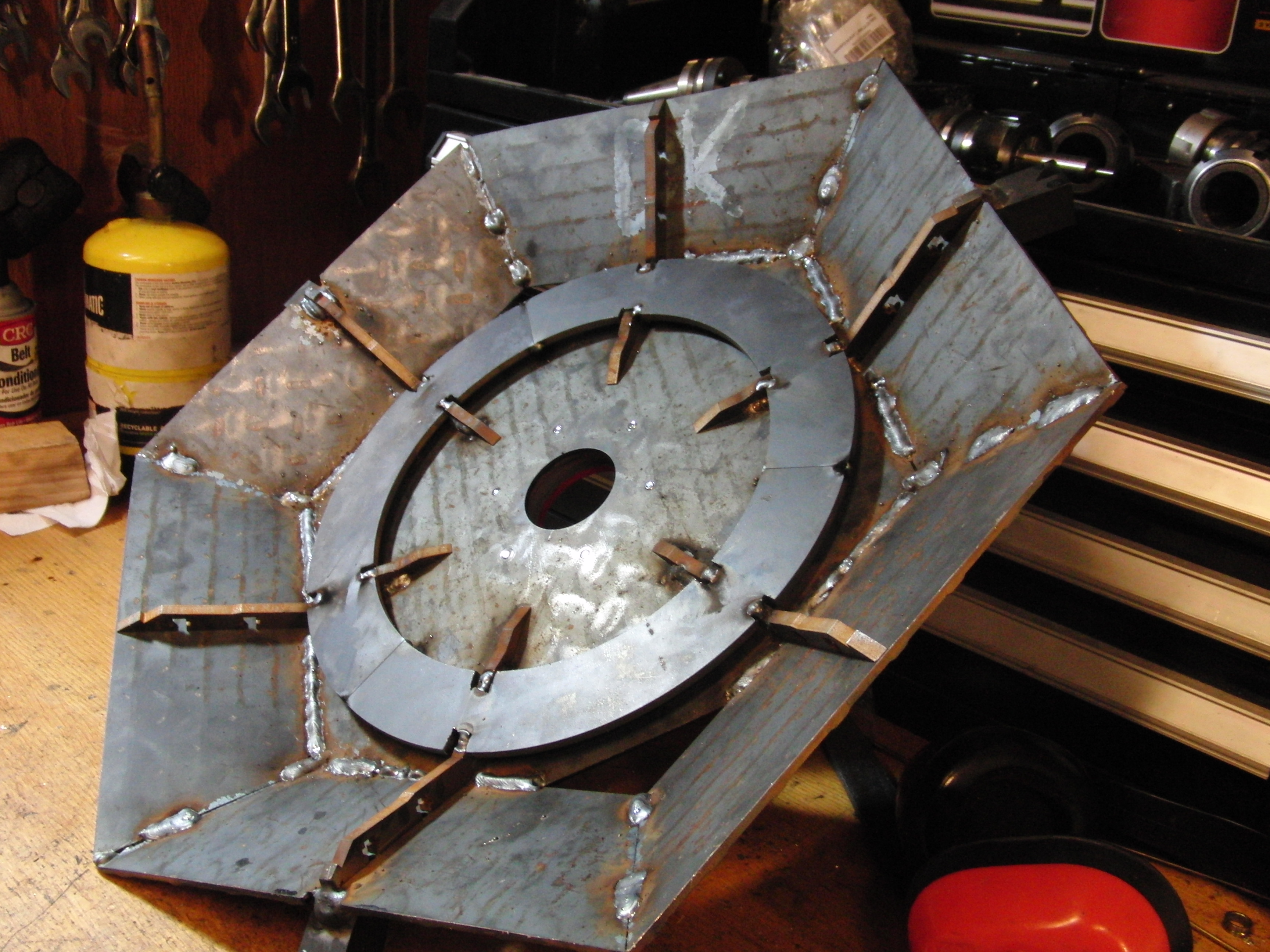 |
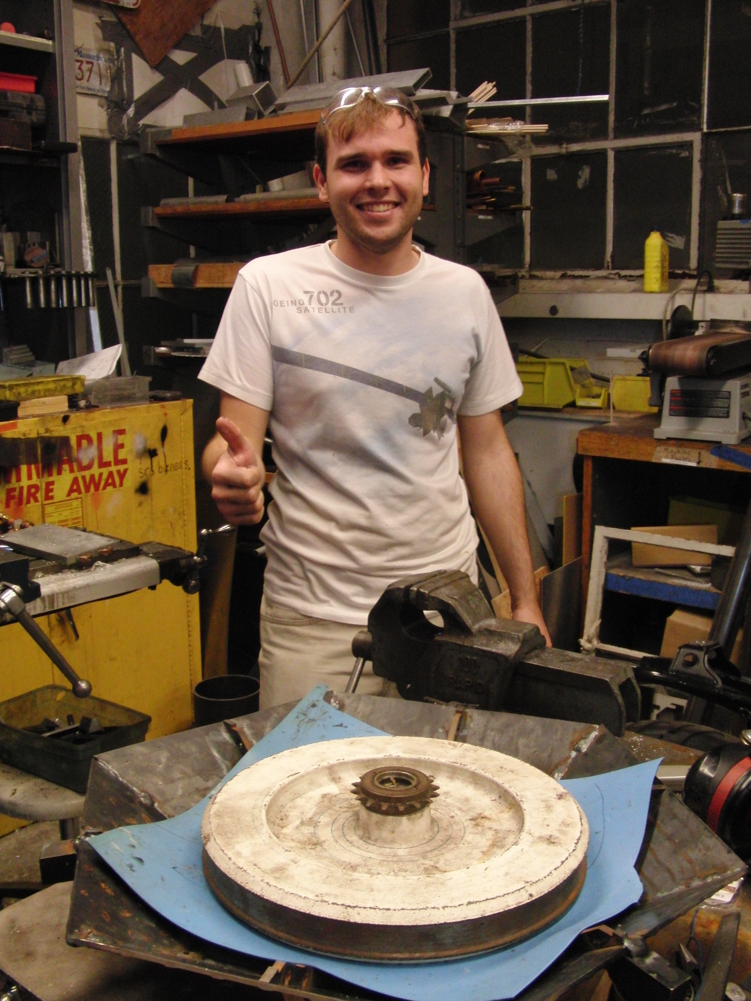
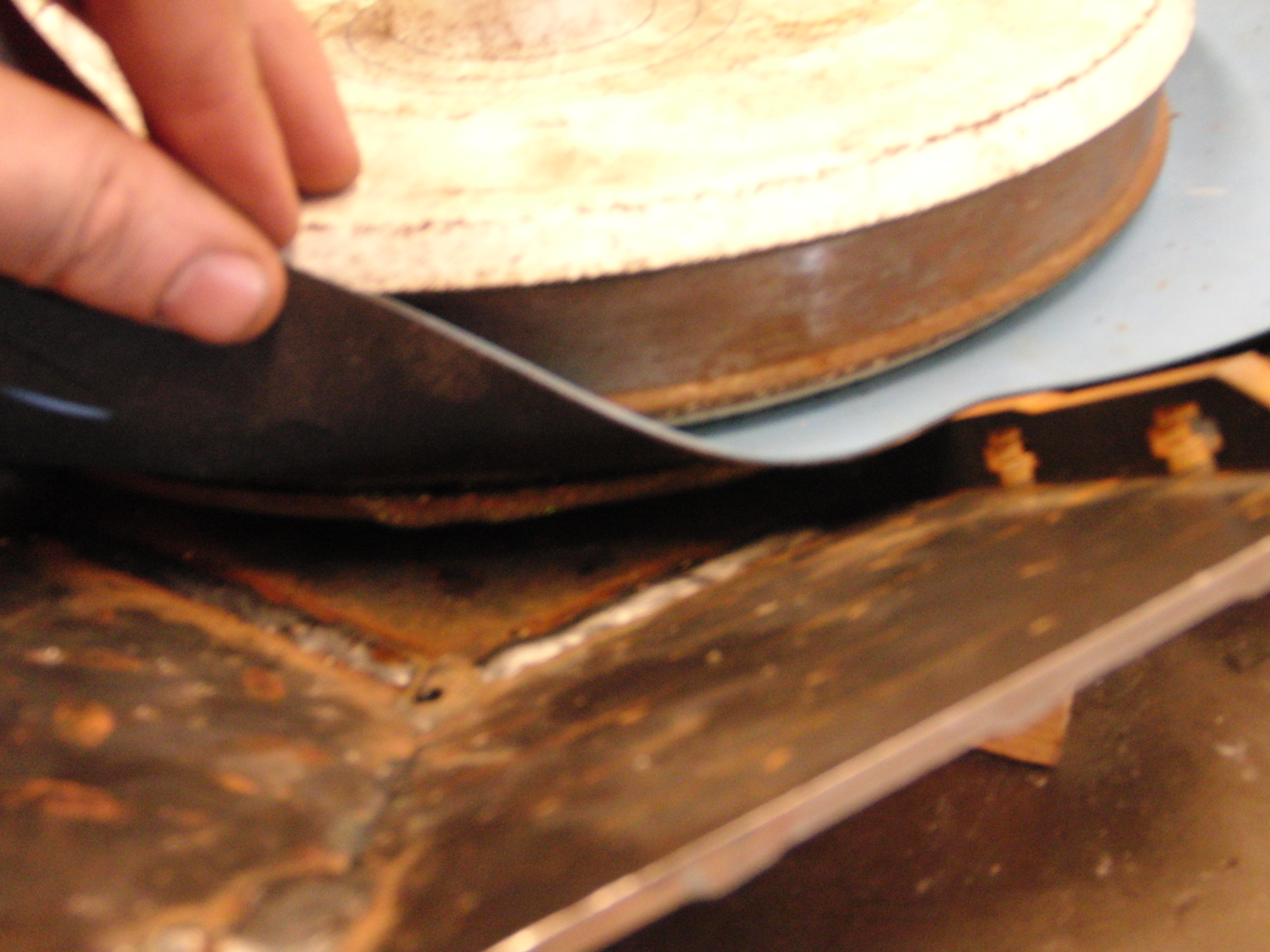
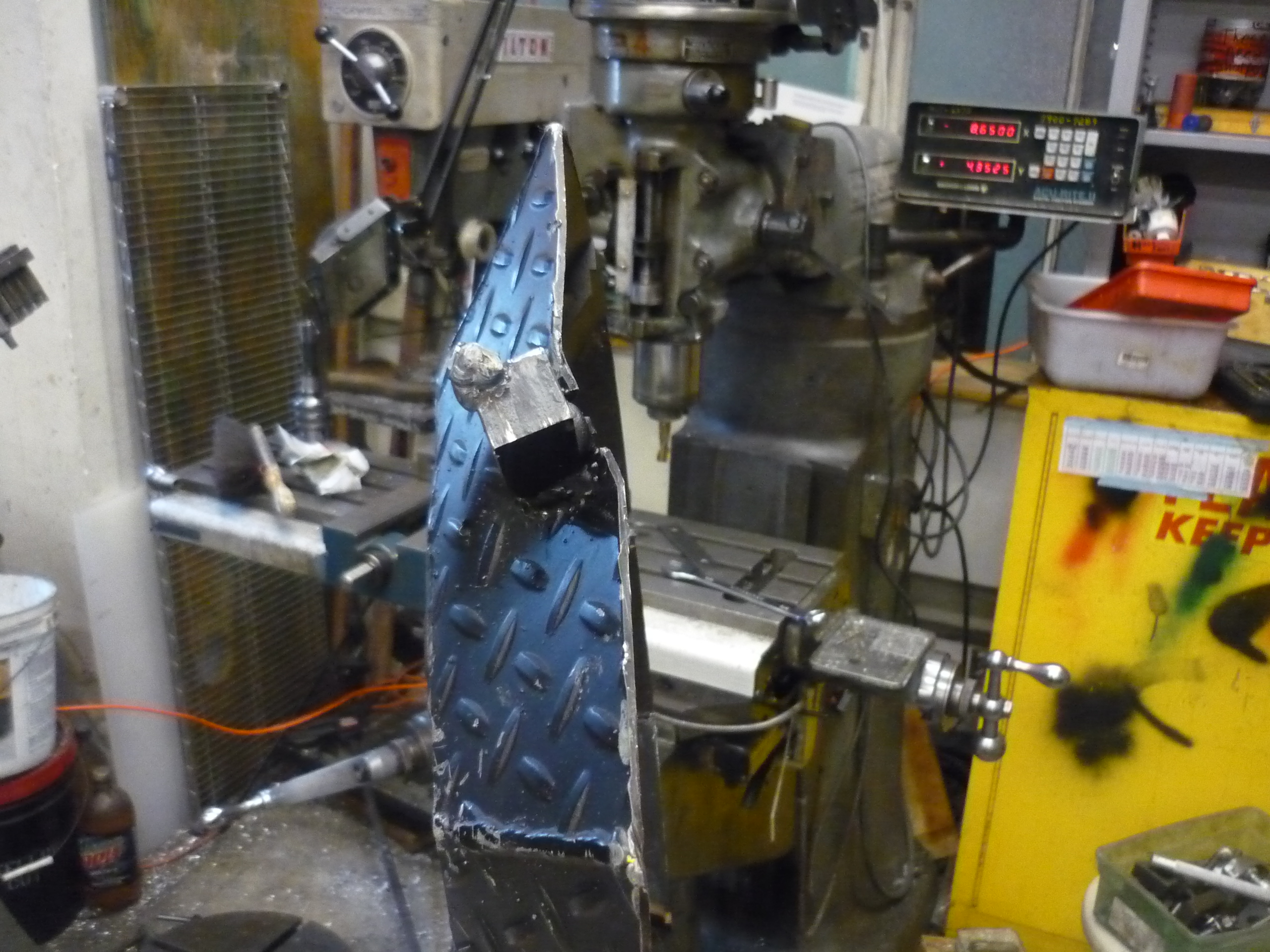
| Adding
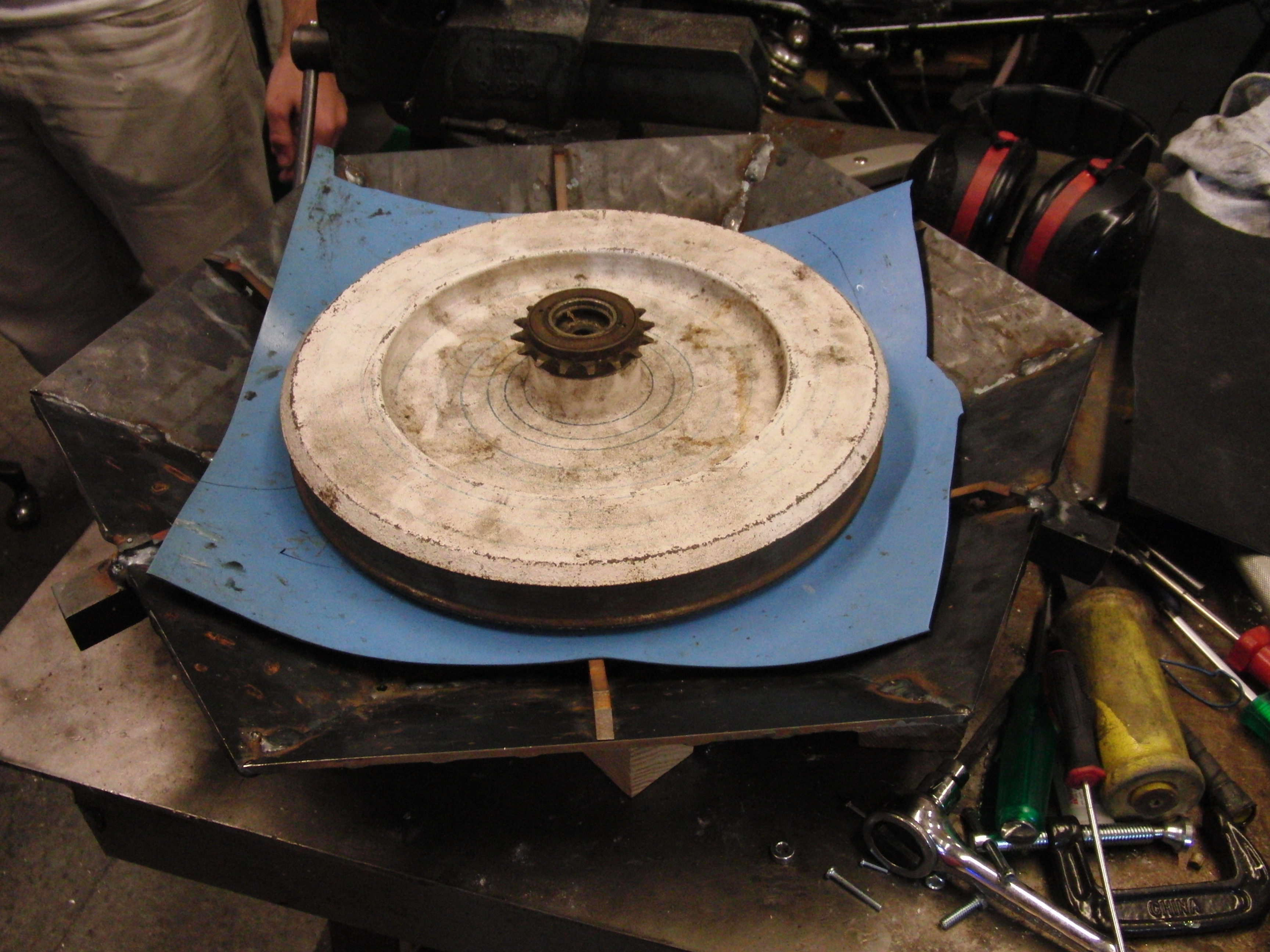
a rubber footing I used a propane torch to super-heat the racetrack assembly, and then draped 'miters sparkly hot glue' around the track. The specific heat of the steel allowed for the glue to melt in and form a fairly uniform layer. While hot, and with the help of Peter Krogen, I stretched very heavily used Blue ESD mat over the track assembly. A large flywheel weigh was placed on top of the mat to help it cool in a flat fashion. Afterwards an x-acto knife was used to cut the mat into racetrack shape. |
 |
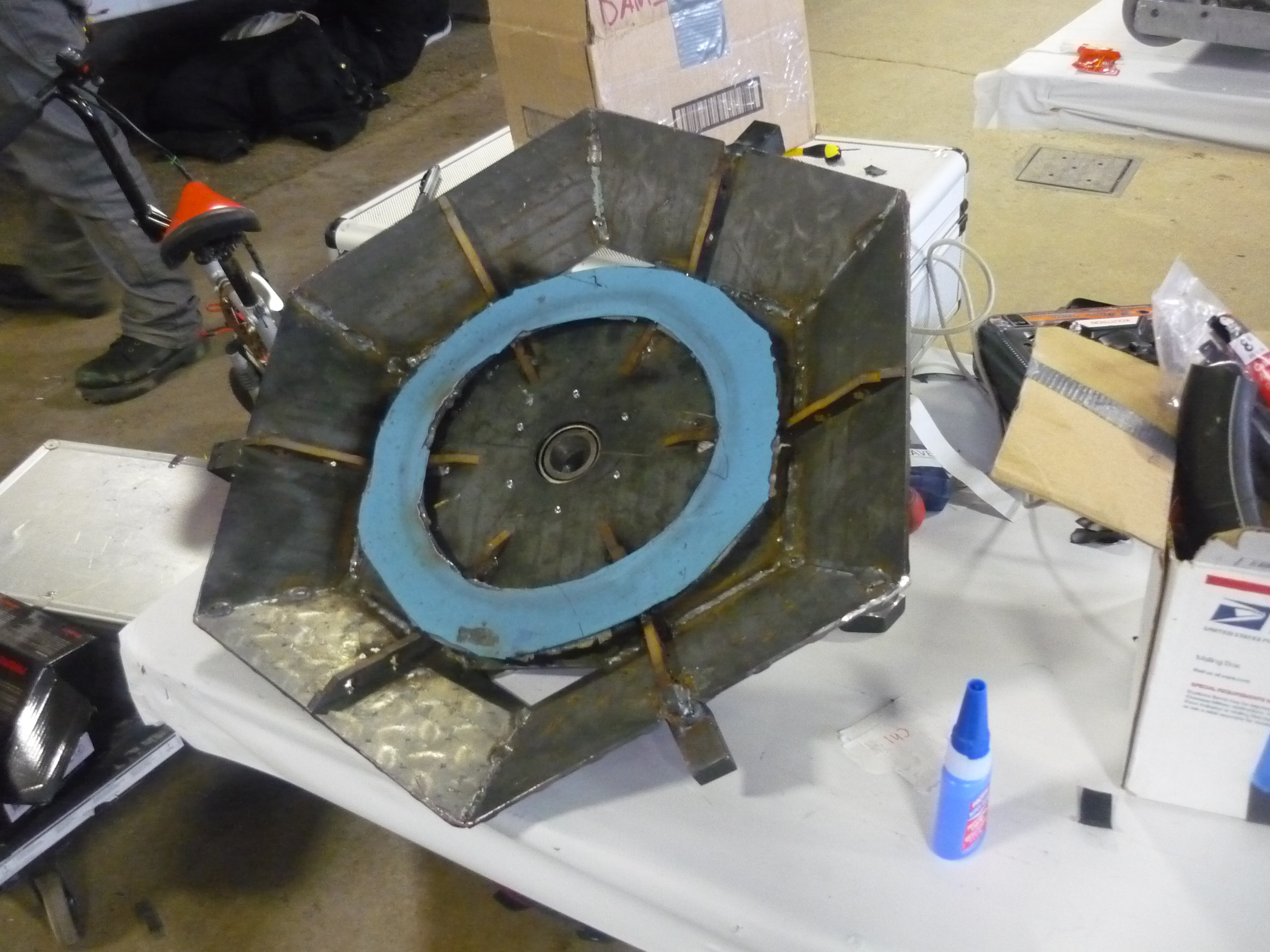 |
| Cooling
Time It took a fairly long time for the steel plate to cool. Afterwards the mat was surprisingly well bonded to the plate assembly. The mat provides a rubbery grip surface that the shell motor spins on. This worked far better than expected, as the rubber mat bonded well to the racetrack assembly and was a high enough durometer to not fall apart under high load (shell spoolup) |
 |
 |
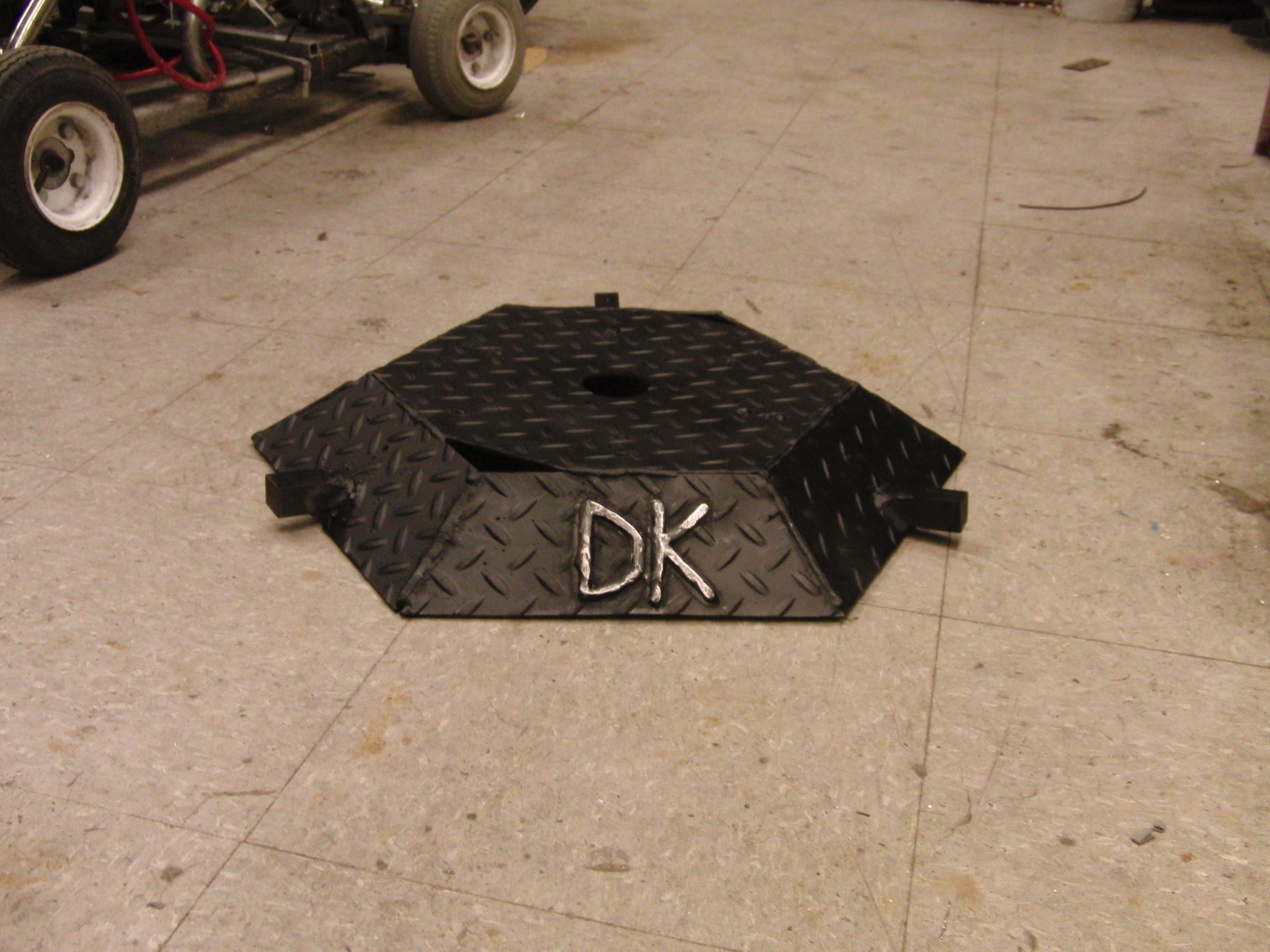
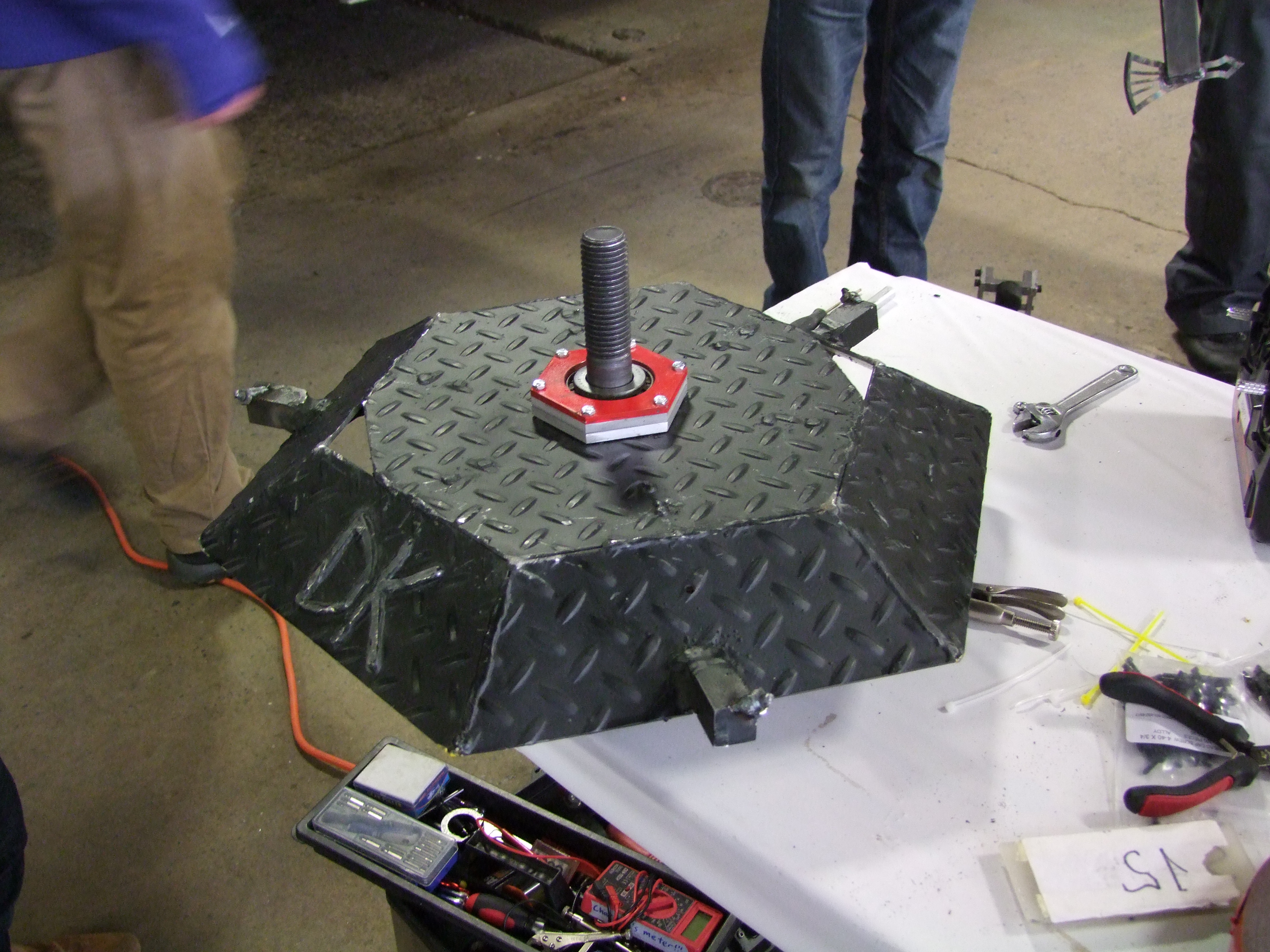
| Paint As much as i enjoyed the rusty delerict steel look i decided a coat of mate black paint on the shell would add a bit of legitimacy to this haistly thrown together project. The letters DK were added on during the shell welding session, and ground flat after painting to help the letters pop-out. I used a self-etching primer (gray) coat and then followed it with a matte black coat of paint. |
 |
 |
Baseplate Build
Propulsion
| Buildtime |
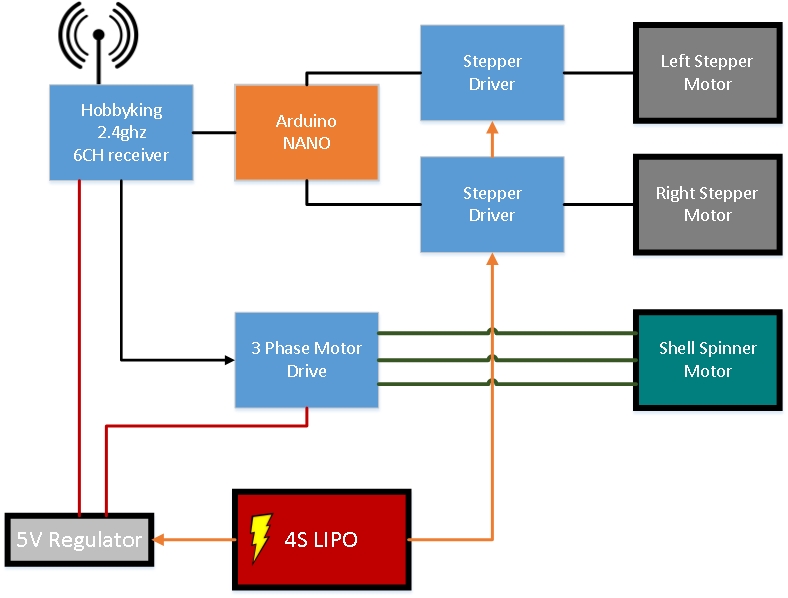
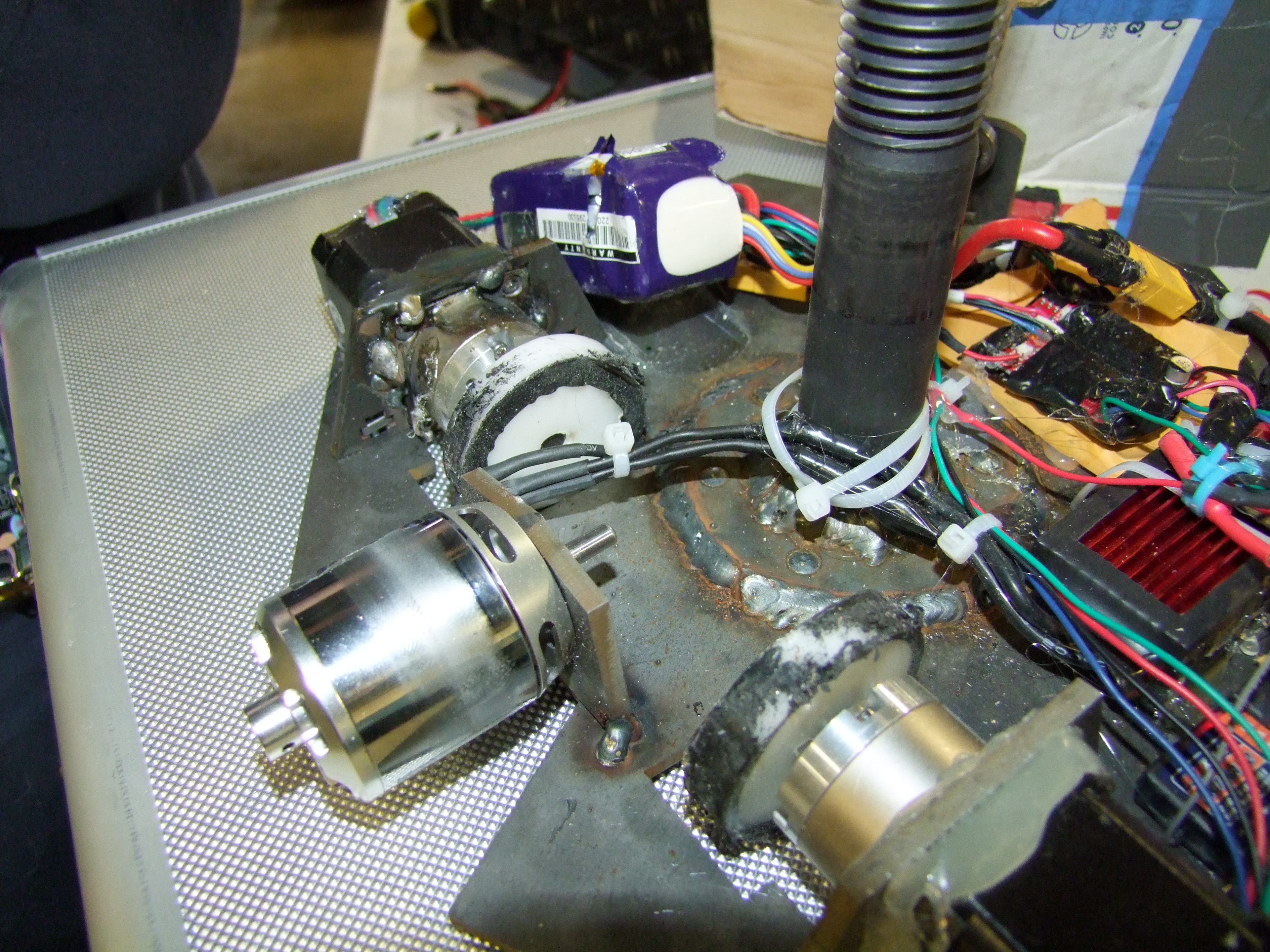
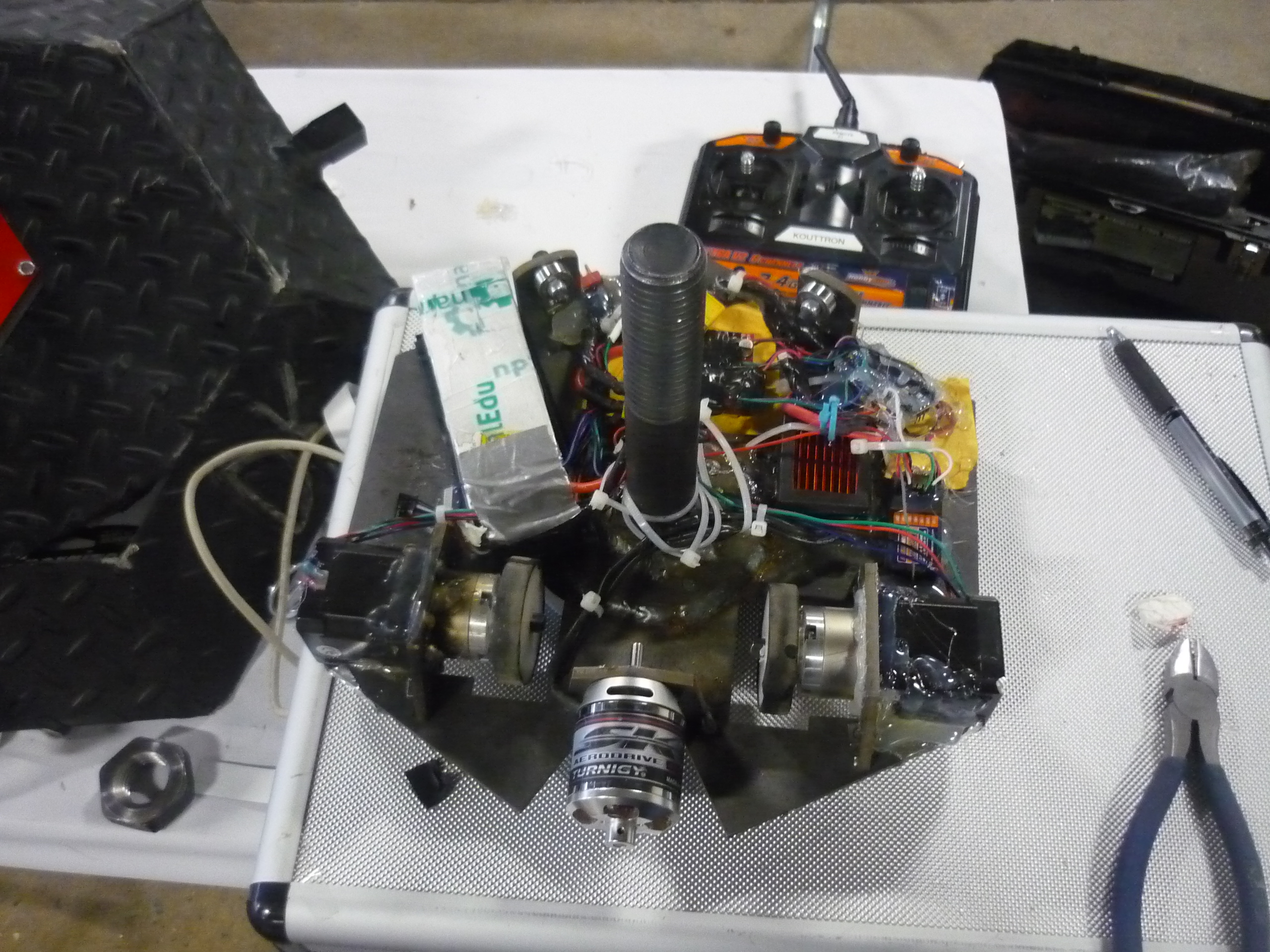
| The
motor control for the steppers and shell spinner is tied into the
sporadic motor controls / shell spinner control setup, shown right.
Everything is fed from a 4S lipo brick, and either regulated down for
logic or run hard for the motors. An XT-60 connector is used as the 'on-off' switch, it disconnects the battery supply from everything else. The arduino nano receives PWM input from two of the 6 channel receiver, parses the pwms for each channel, and then modulates the stepper motors accordingly. This provides front-back / left-right control of the robot. The radio potentiometer sets the shell spinner speed, which is translated into a PWM used to control the shell spinner 3 phase drive |
 |
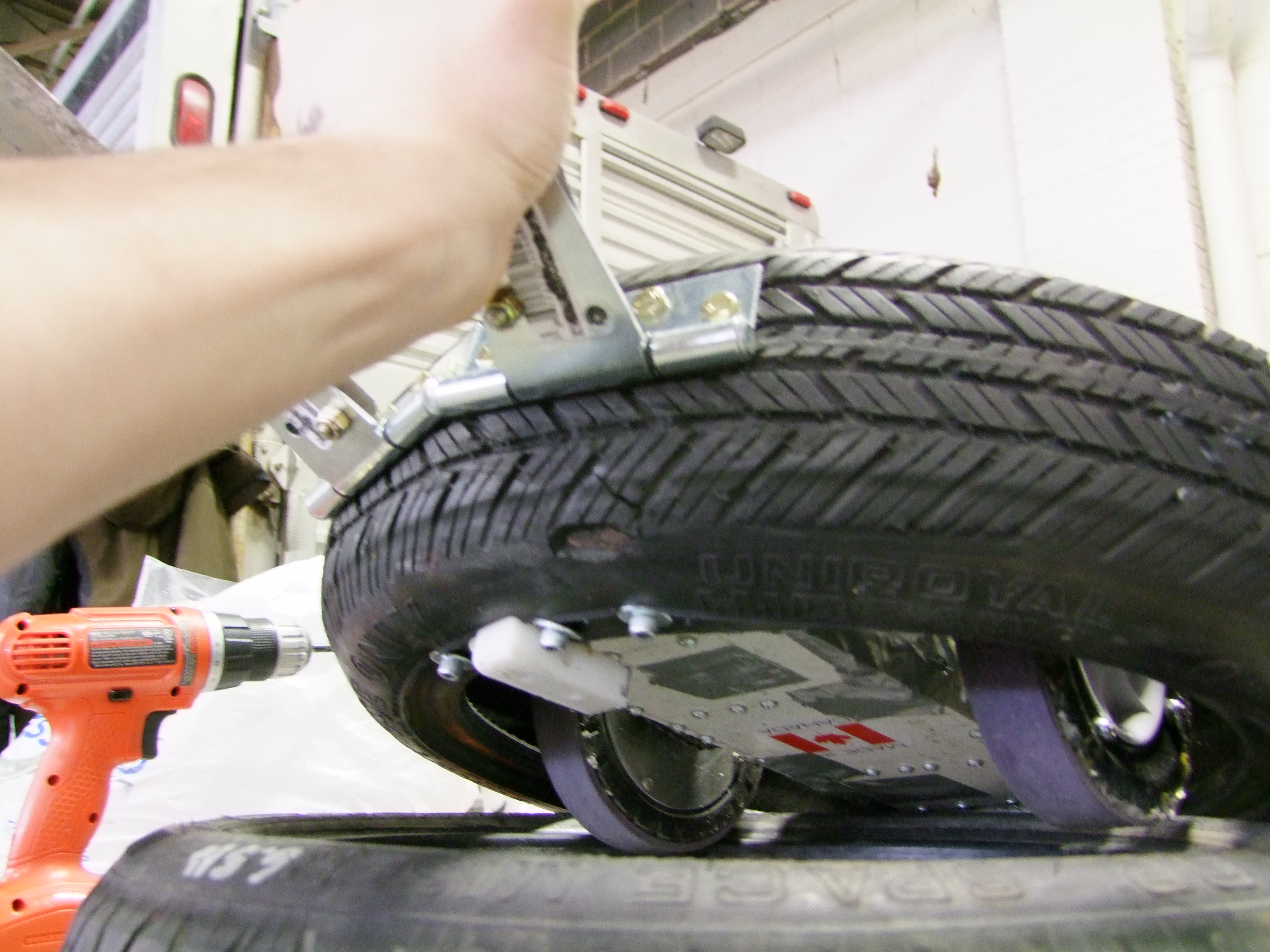
| Rear
roller wheel The rear wheel, detailed below in the BOM, was epoxy-glued in place in a pre-cut hole designed for it to sit in. the whole vehicle now was the two front wheels an a rear roller assembly. This makes turning fairly difficult as the whole bot wants to pivot around the center of the 2 wheel assembly, in tank-steering state. |
 |
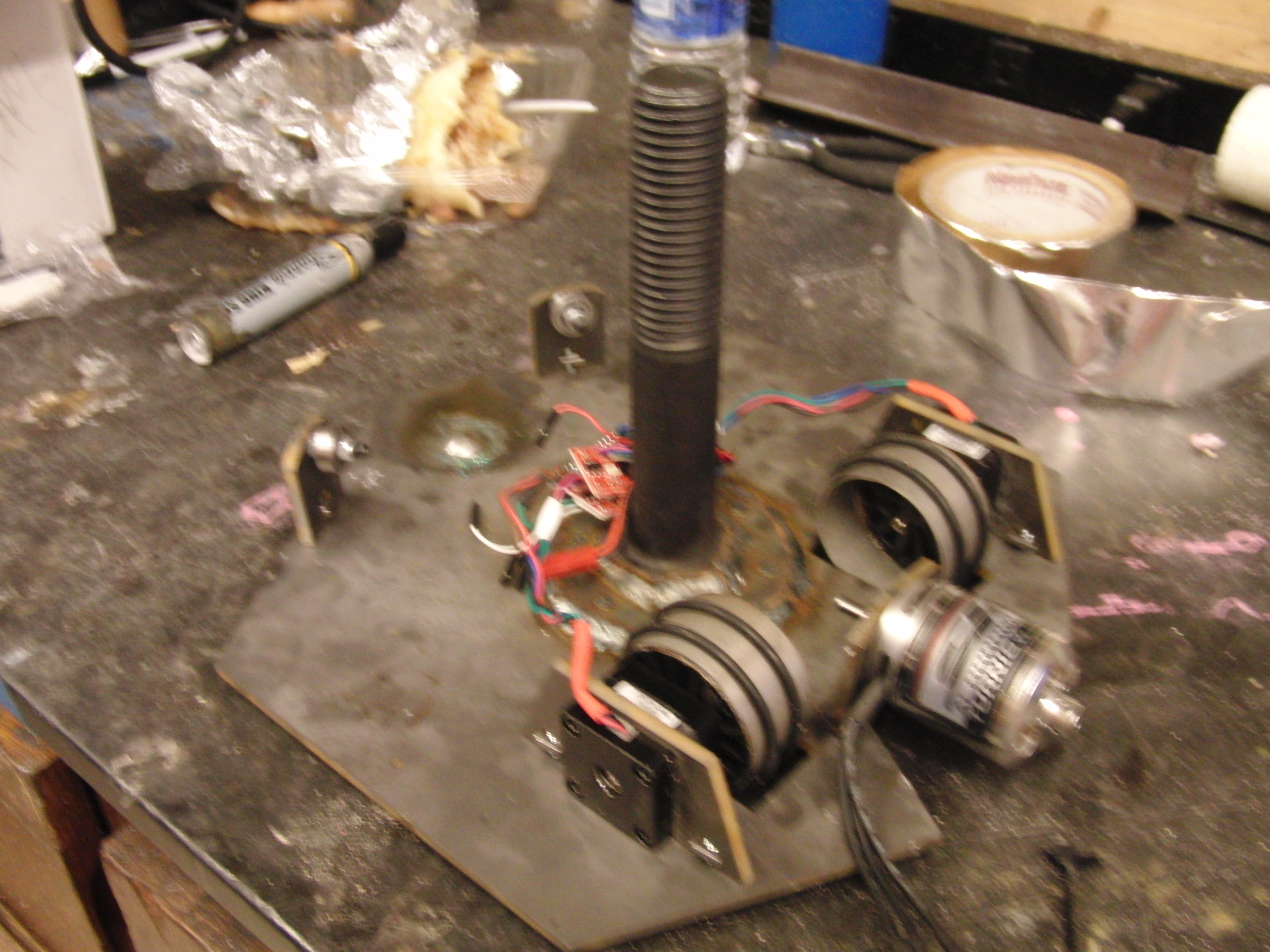 |
| last
minute stepper upgrade Due to some issues burning out the initial steppers, radical changes were made, the mistakenly ordered 5:1 gearboxes were shoe-horned in place and epoxy/welded to the frame. Parts of the frame were removed to accomidate the increased mass of the motors and provide some clearance. Copious amounts of 2-part epoxy were used to keep everything in place. After some twiddling THERE WAS PROPULSION! It was slow and the stepper drivers were fairly anemic, but it was propulsion nonetheless. |
 |
 |
Code
| Buildtime |
| This
was drafted on the car-ride to motorama. Due to a hardware issue, (I
had blown out the FTDI usb-serial peripheral on the arduino nano), I
was using an AVRISPMKII programmer. There was an issue with that route. I had 'arduino nano 3.3v 8mhz' selected as the compilation target, which, tells the on board ATMEGA328 to use its internal RC oscillator instead of its on board 16mhz crystal. As a result the timing is off by a factor of two :/ This was found by Aaron Fan, I was banging my head into the table trying to figure out this issue right before safety qualification occurred. Aaron saved the day and cleaned up a bit of my case-statement mess. CHECK YOUR FUSEBITS AND PROGRAMMING TARGETS KIDS. there's a few issues with the way this is implemented. It takes time to poll the RC receiver pins (2), and because the timing for the steppers is software generated, it results in a bit of a tradeoff between latency and max stepper speed. Ideally this should be implemented with interrupts and a counter to keep track of the input ppm signal from the receiver. |
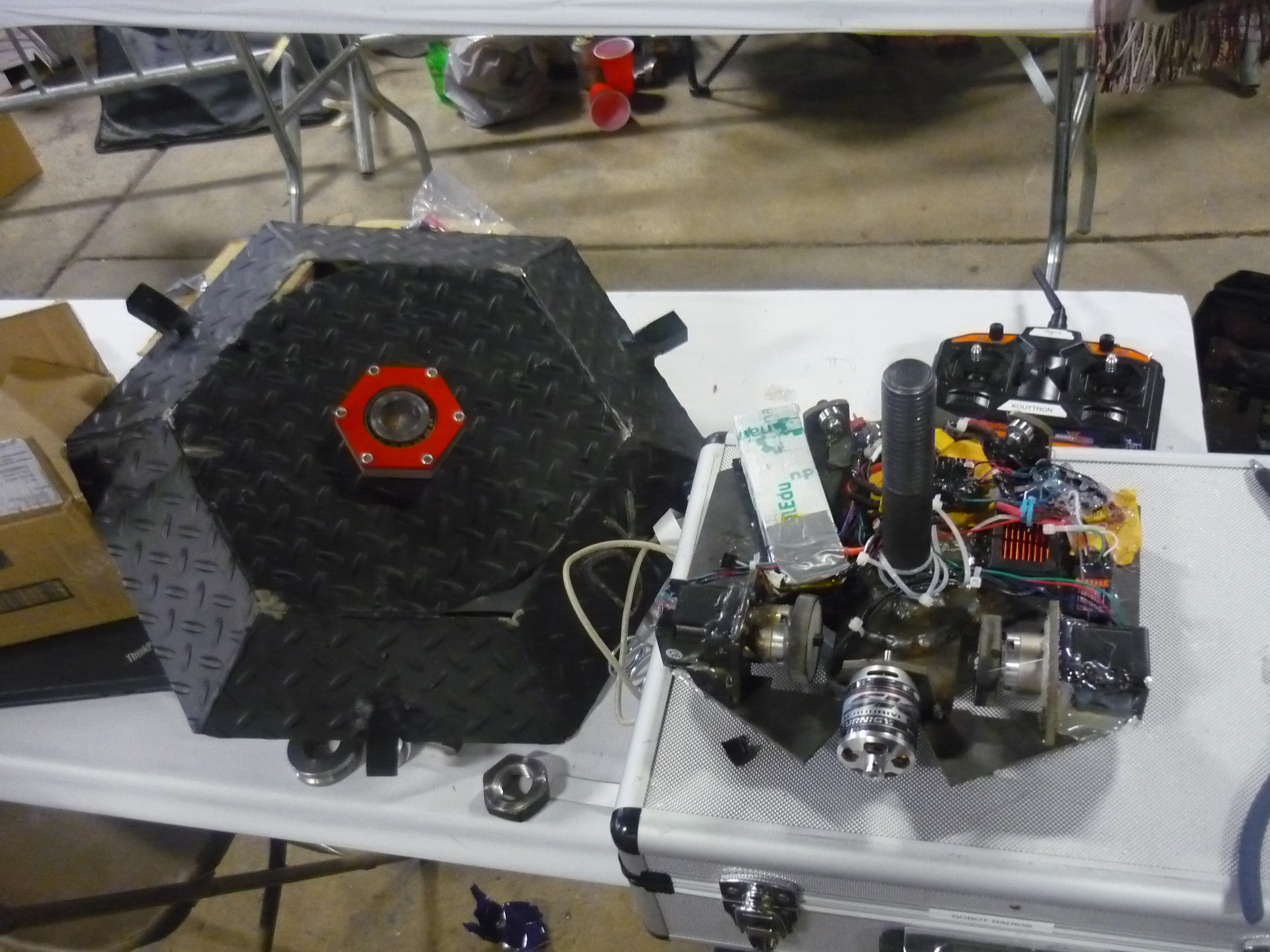
Getting ready for battle

Bill of Materials
| Description | Part number / link | Description |
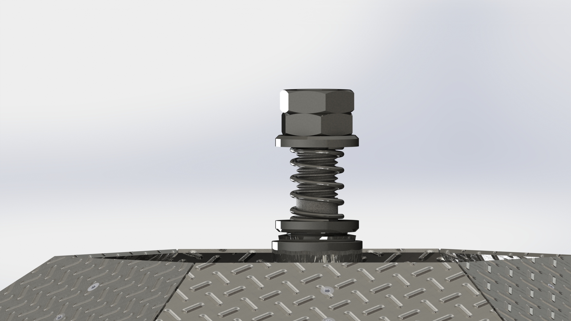
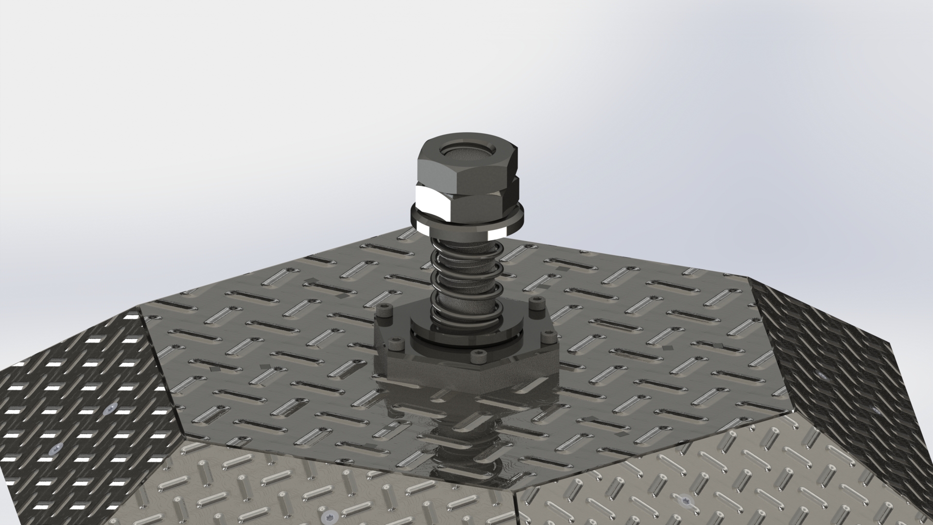
| Mondo Washer | 91201A039 | Plain Steel Extra-thick Flat Washer, 1-1/8" Screw Size, 2-1/4" Od, .3"-.33" Thick |
| Main compression spring for | 9657K409 | Steel Compression Spring, Zinc-pltd Music Wire,2.00"l,1.460"od,.135" Wire |
| 91268A125 | High-strength Steel Cap Screw - Grade 8, 1-1/8"-7 Thread, 6-1/2" Long | |
| 90502A430 | Plain Grade 2 Steel Extra-wide Thin Hex Nut, 1-1/8"-7 Thread Size, 1-13/16"w, 39/64"h | |
| 91290A252 | Black Class 12.9 Socket Head Cap Screw, Alloy Steel, M5 Thread, 25mm Length, 0.80mm Pitch | |
| Rear ball roller wheel | 2415T13 | Countersunk Flange-mount Ball Transfer, General Purpose, 5/8"stl Ball, Stl Housing, 20#cap |
| 90576A104 | Metric Zinc-plated Steel Nylon-insert Locknut, Class 8, M5 Sz, .8mm Pitch, 8mm Width, 5mm Height | |
| 92703A353 | 18-8 Ss Flat Head Torx Machine Screw, 10-24 Thread, 3/8" Length | |
| 94855A123 | Grade 2 Steel Square Nut, Plain, 10-24 Thread Size, 3/8" W, 1/8" H | |
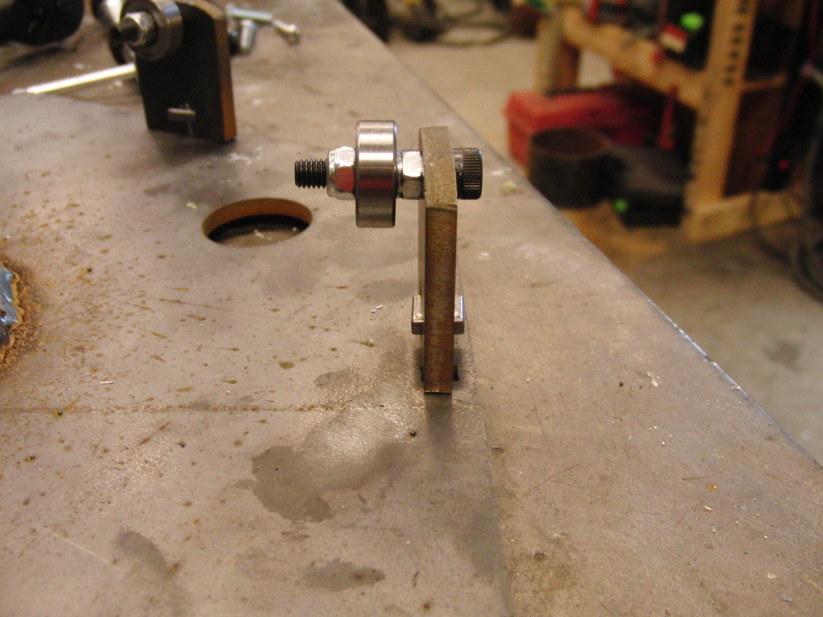
| Secondary shell spinner roller bearings | 6384K52 | Steel Ball Bearing, Plain Double Shielded For 1/4" Shaft Dia, 11/16"od |
| Primary shell spinner bearing | 5709K22 | Steel Tapered-roller Bearing, Roller Assembly For 1-1/8" Shaft Diameter, #15113 |
| A36 1/4" thick steel plate | Link | ASTM A36 Hot Rolled Steel Plate (shell braces) |
| A36 1/8" thick steel diamondplate | Link | ASTM A786 Hot Rolled Steel Floor Plate Print Print (shell top, shell skirt plates) |
| Hobbyking shell spinner motor | Link | Kv (rpm/v)
350,
Weight (g) 266, Max Current (A)
53. Power(W) 1190, Shaft (mm) 5, Length (mm) 58, Diameter C (mm) 42, Can Length D (mm) 33, Total Length E (mm) 80 |
| Hobbyking 100A 3phase ESC | Link | 90A, 100A Max. 7S LIPO max voltage. |
| 4S lipo battery | Link | Capacity(mAh)
1300,
Weight(g) 155, Length-(mm)
73 Height-(mm) 35, Width-(mm) 31 |
| Arduino nano | Link | spare, semi-broken from prior project. |
| 2x mini stepper drivers | Link | From previous battlebot, crufted from lab cleanout. Under-powered for this application. Linear stepper drives with max current of 1A. |
War Wounds
| FIGHT ROBOTS FIGHT | ||
| Pre-fight
Before battle the shell was completely black and the three 'whacker' posts were tangential to the central shaft. |
 |
 |
| The
fight with MEGATRON The first battle of the day was against megatron (created by the seasoned battlebot veteran JAMO). The bumble survived a number of circ-saw cuts to the shell shown right. Fortunately there is a lot of shell here. There was a bit of mechanical jostling and somehow the internal 4S lipo went kaput on the bumble. After the match it was determined that a portion of the shell had to have collided with the lipo during an impact. This cut power towards the end of the match. The lipo was haistly hot-glued in place and it was more than possible that mechanical impacts could have dislodged it. |
 |
 |
| Lipo
impact Here's a view of the impact with the lipo. Its at an odd angle and probably came about from the shell being dislodged / loose during an impact. If the tensioning spring is loose, an impact will shift the shell over temporairally. Its a good thing the cell wasn't punctured! The vulcanizing-tape tire treads also seemed to come apart after a bit of rough use. Legitimate tires would have helped significantly instead of slippery delran plastic, but it was enough to move. |
 |
 |
| Last
minute battery. With the 4S lipo mechanically 'derped' I was a bit upstream without a paddle, fortunately a sketchy lipo, which had been brought as an emergency backup from the 'atomic stockpile'. After a bit of surgery, the 5S lipo (with 1 dead cell) became a 4S lipo, and was shoe-horned into the chassis. It had about 1/8'th of an inch clearance to the shell racetrack. |
 |
 |
| Upgrades
for the Canadians I had the advantage of knowing that i would be soon combating the canadian bot 'ROBot FORD', so, with the help of the wunderbar welder bercu, screws were welded to the mighty steel posts on the outside of the shell. The logic was "Tires really dont like screws" While all 3 screws were lost into the tire, the canadians, added a 'push from that tall bar thing' addition to their bot, which allowed them to keep me at bay. only a few hits sunk in, but some bit of tire bled off so I was happy. |
 |
 |
| Impact
with CANDY PAINT & GOLD TEETH In a grudge match with the SUPER INTENSE INVERTED LAWNMOWER candy paint, piloted by Bercu (shown below) the 'whacker' arms got a bit 'bent'. Keeping in mind that this is 1/8" steel, there was quite a bit of imparted energy here. It take a bunch to bend that stuff, next time, more reinforcement! |
 |
 |
| More
shots of the Damage Thats a lot of bend! More reinforcement for the next shell. |
 |
 |
| Candy Paint vs Atomic Bumble Prime |
| What happened: I started the fight with the weapon at 'full' when I woke up the remote. As a result the controller defaulted in a safe mode and i had to spin it down to 0 to restart. By the time i had the weapon back the first blow was struck, and due to the shell angle on candy paint, the bot spun away pretty fantastically. Huzzah. |
(There's
other photos in the photo
gallery)
Concluding
Remarks:TIME! It takes a while to get a working bot ready for the northeast robot superbowl. NOT 3-4 DAYS. Practicing, learning the performance of the bot and working out kinks are activities that should not happen first on the battlefield! HEED MY WARNING!
Spending time on propulsion could have made a significant difference in the robots performance. Steel worked really well for everything, although, I wish I had spec'd thinner stronger steel alloys, the floor-tile, while strong, wasnt nearly as sturdy as some chromoly steel alloys. If more time was spent on mass allocation I would have probably taken the time to add an inner skirt assembly to give the shell more torsional rigidity, and also anchor the 'smasher bars' into the shell frame better.
This could have not come together without some awesome folk: The Bercu, joiner of metals, Brian Chan and the Hobbyshop-ians, for letting me use the OMAX SLICER OF METALS, Charles G, for providing transport, design feedback and a metric boatload of connectors, wires and whatnottery. The folks in the land of FSAE for welding access, and of course the MITERS, whom i nicked the floor fairly well when spinning up this beast. You folks are awesome.
The 'walker' classification also peaked my interest, it allows for an extra 50% mass for the bot, future revisions of this bot might benefit from being a shuffler bot, although I'm slightly concerned that the 'bouncy' nature of walker/shuffler bots might cause a shell-spinner to become unstable. There were 2 'walker' class shufflebots at motorama, both were pretty darn awesome and worth oogling at.
If you have questions or comments, ask below or send over an email.
| Comments: |
|
HTML Comment Box
is loading comments...
|
(be
careful, im not responsible for that mig-welding Tan)
Dane.Kouttron
Rensselaer Polytechnic Institute
Electrical & Electrical Power
631.978.1650
