Dane.Kouttron
[6.20.16] Adventures of StrawberryBot
| This strawberry carrying robot was a quick RC car modification with some interesting lessons-learned along the way. RC cars/trucks make interesting pre-assembled platforms for controllable / autonomous contraptions, this is part 1, the remote-controlled version. Building one that follows about a beacon is the underlying goal, but getting a good idea of the mechanicals and the operating envelope in R/C mode seemed to be a good first pass test. Plottings of beacon-following versions are in the works, follow along for part one and making your own. | 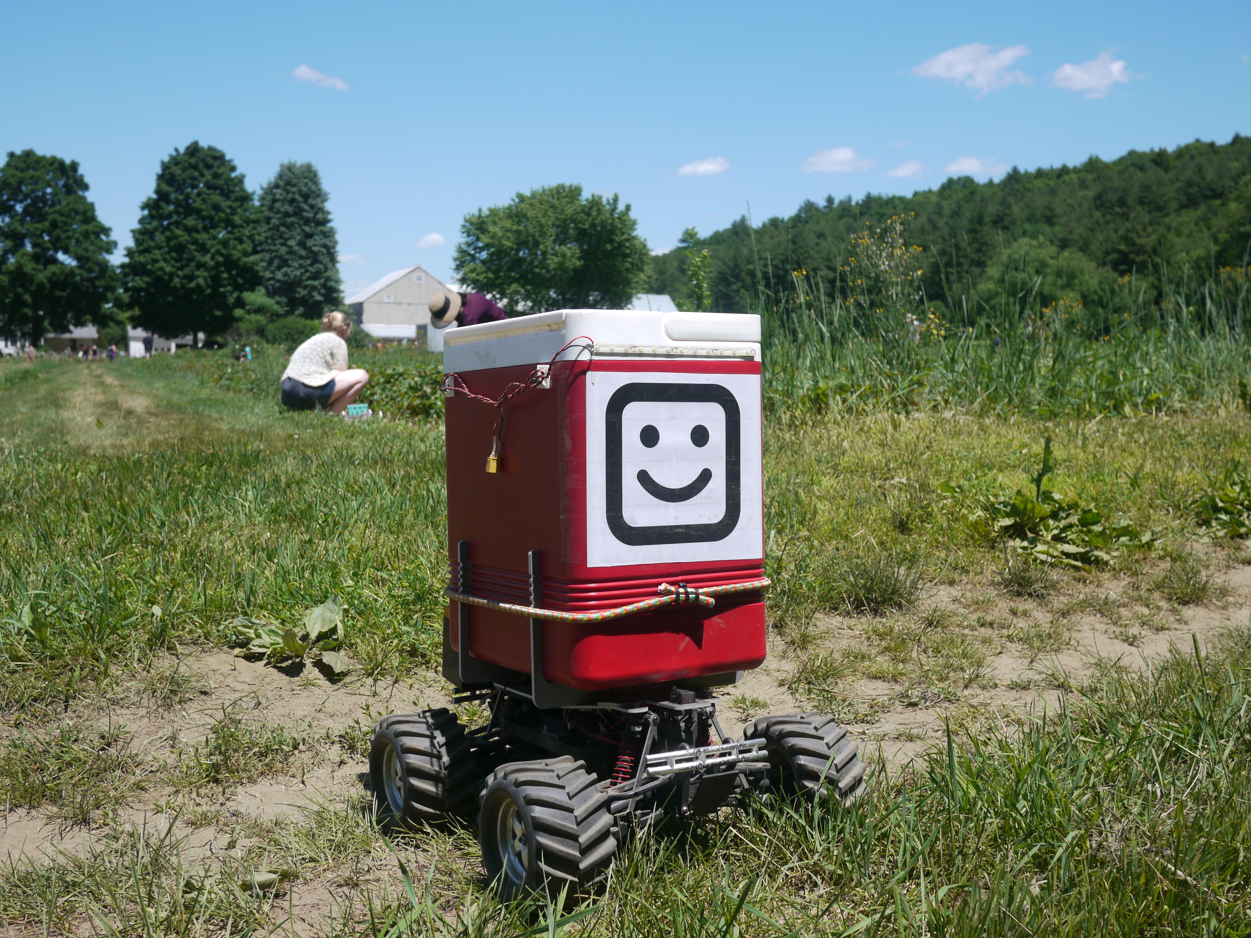 |
 |
| What? |
Chassis and
Construction |
Early Testing [Vid] | Field Testing | Conclusion | Image Directory |
| What? A trip out west to Red Fire Farm for their yearly strawberry shindig was organized by the ever-resourceful Sam. Fresh Strawberry picking is wonderful, but, why carry around dozens of strawberries in the warm sun when a hastily thrown together bot can do it for you? The following details building a remote controlled cooler for chilled fruit transport. May also be useful for chilled beverage delivery on your next beach outing <wink wink> |
| Chassis
and Construction |
||
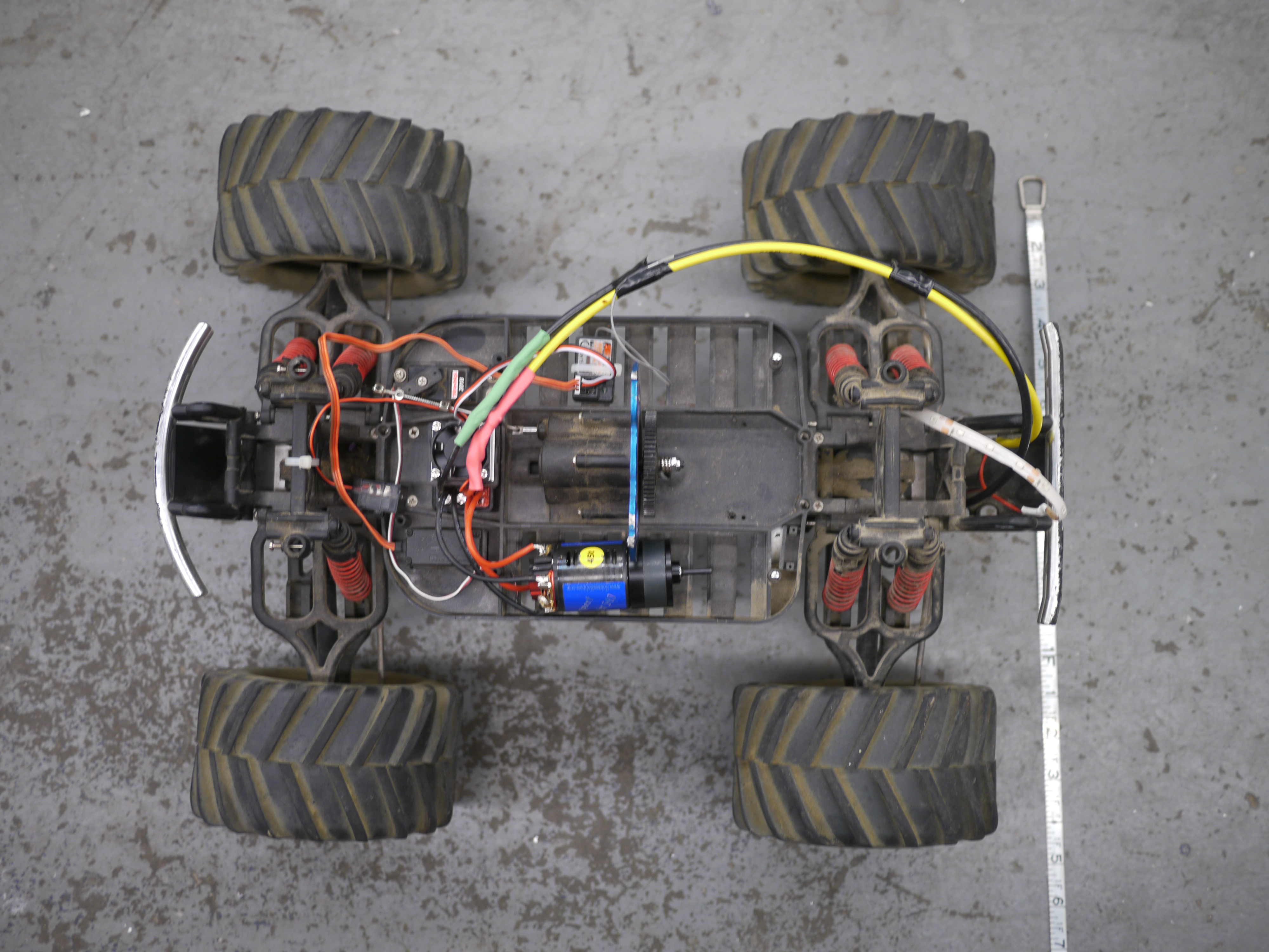
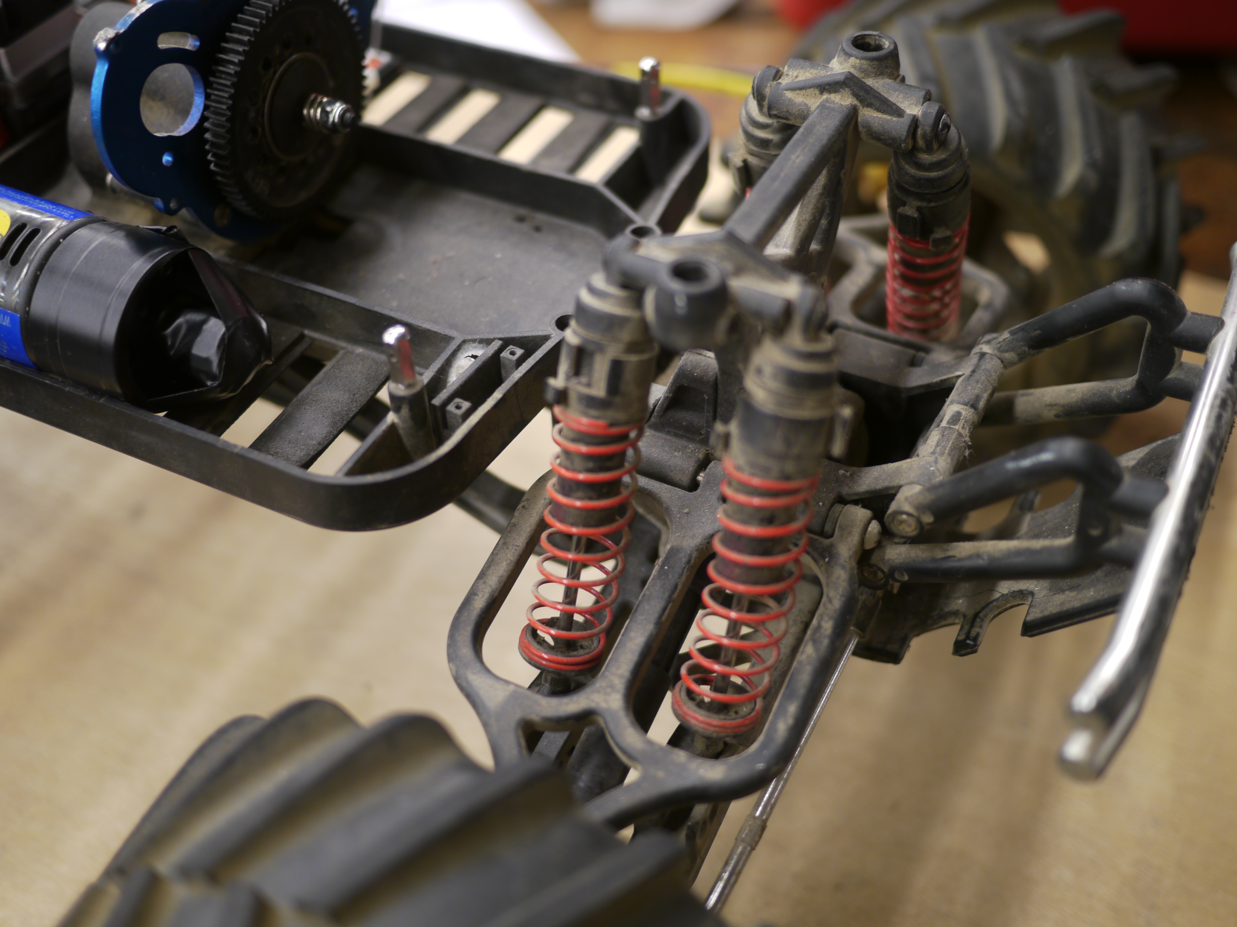
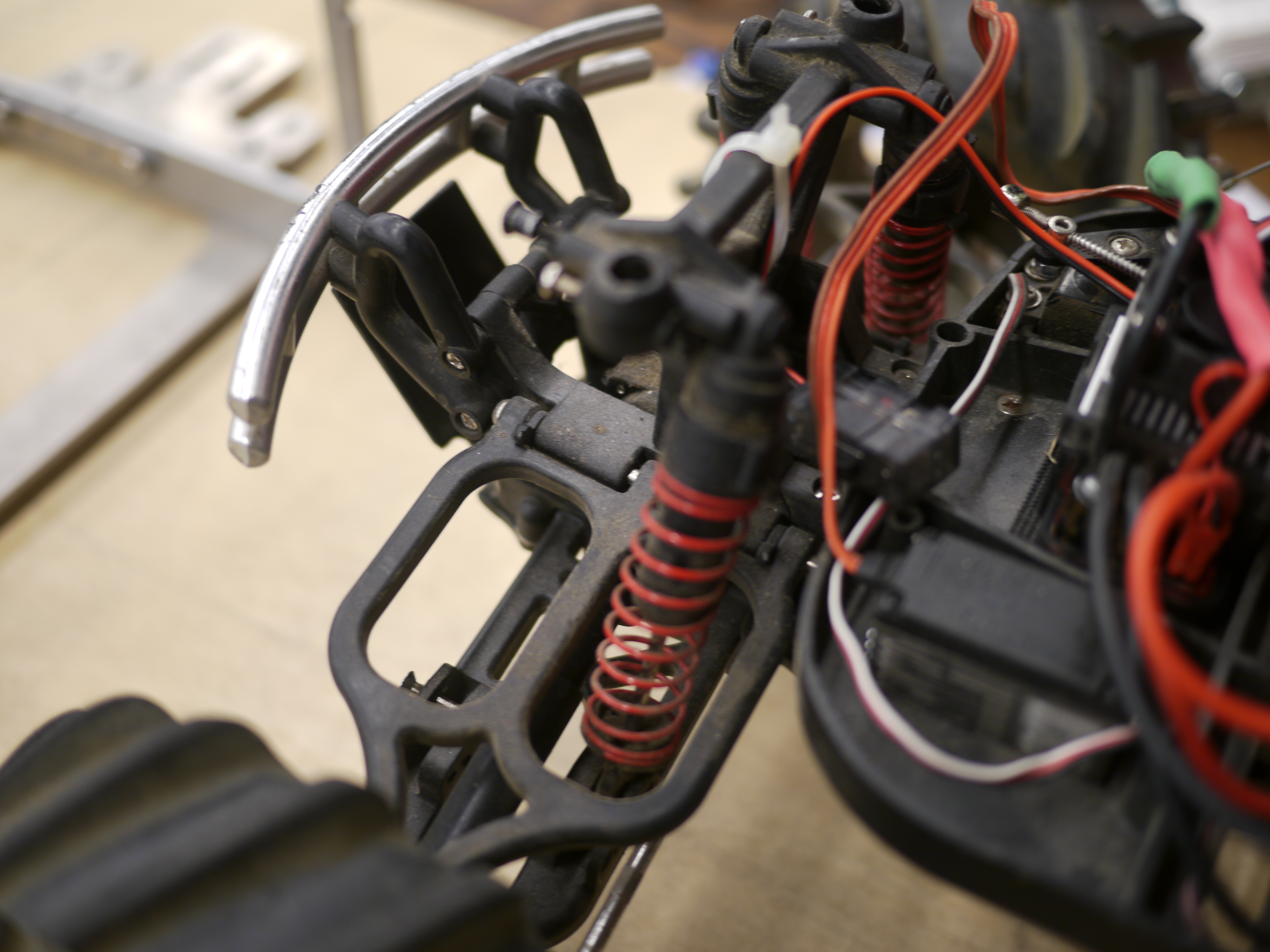
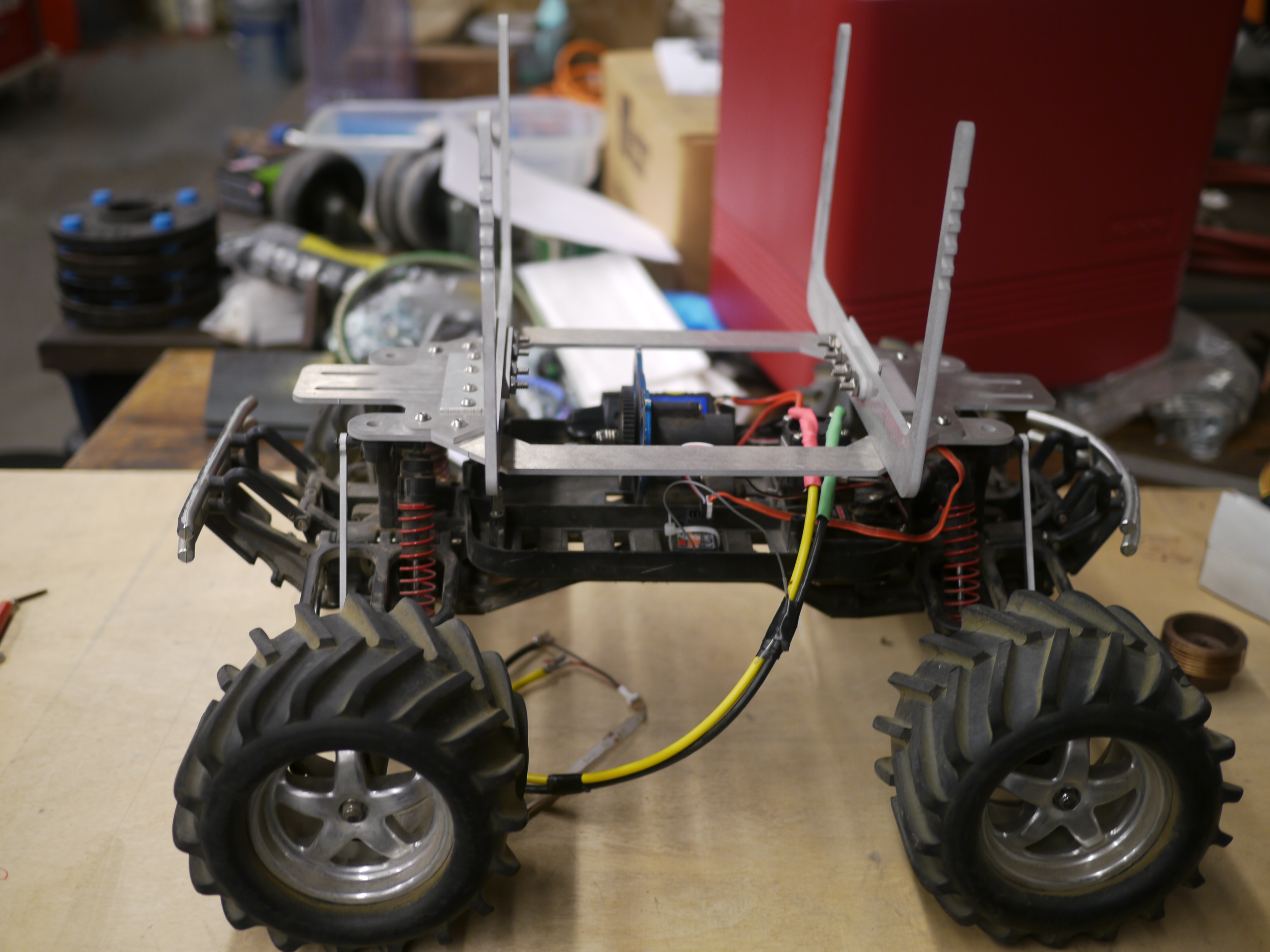
| The chassis for the 'robot' were graciously on loan from the great rock-crawling comrade, Brian. Its an older generation Traxxas emax, 4 wheel drive vehicle that can fit two '540' motors. Note there's quite a bit of swing and suspension hardware. Note the RC car has some curious mounting points and the following goes through some considerations made to get everything to fit and still remain structural. | 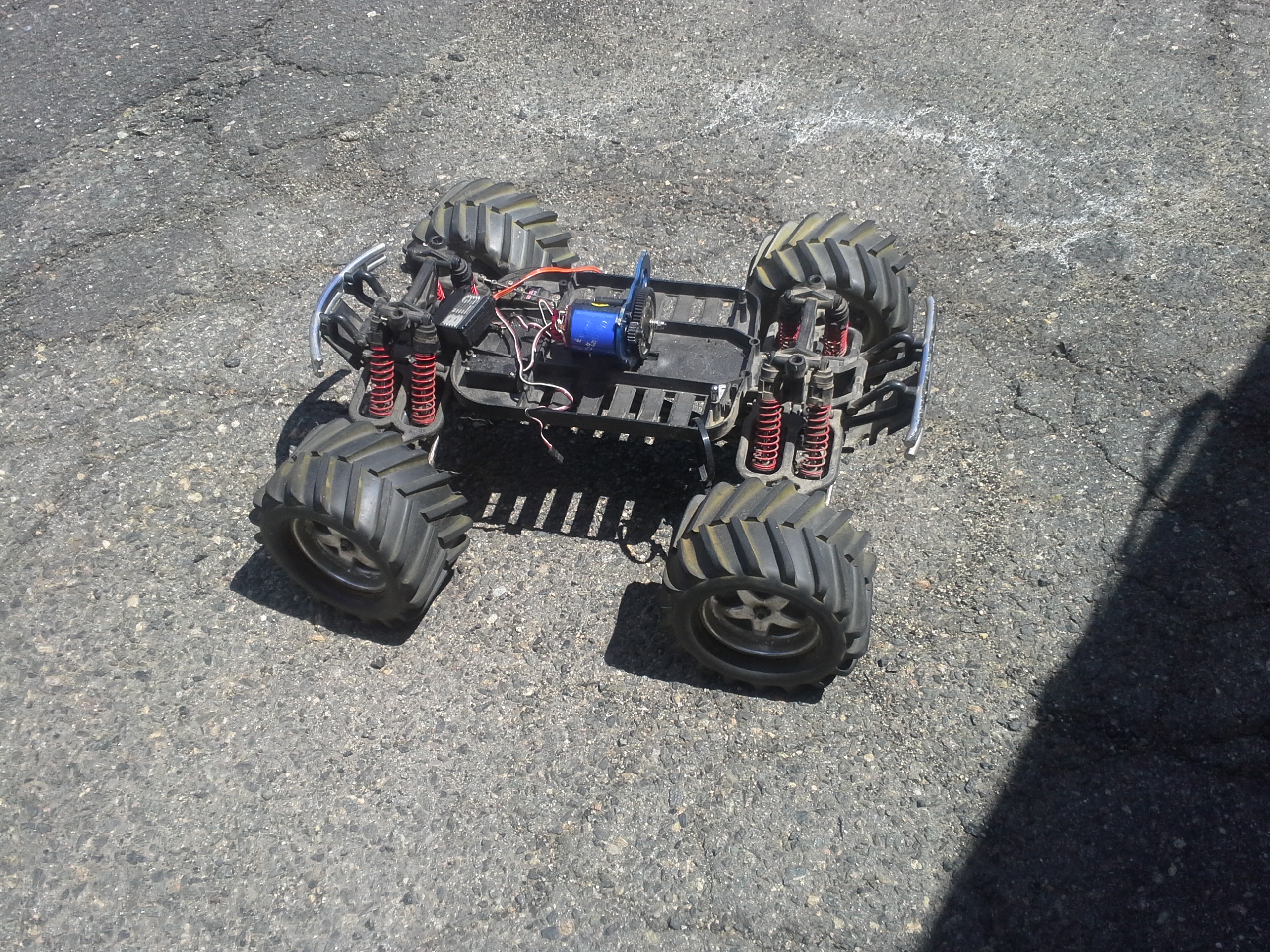 |
 |
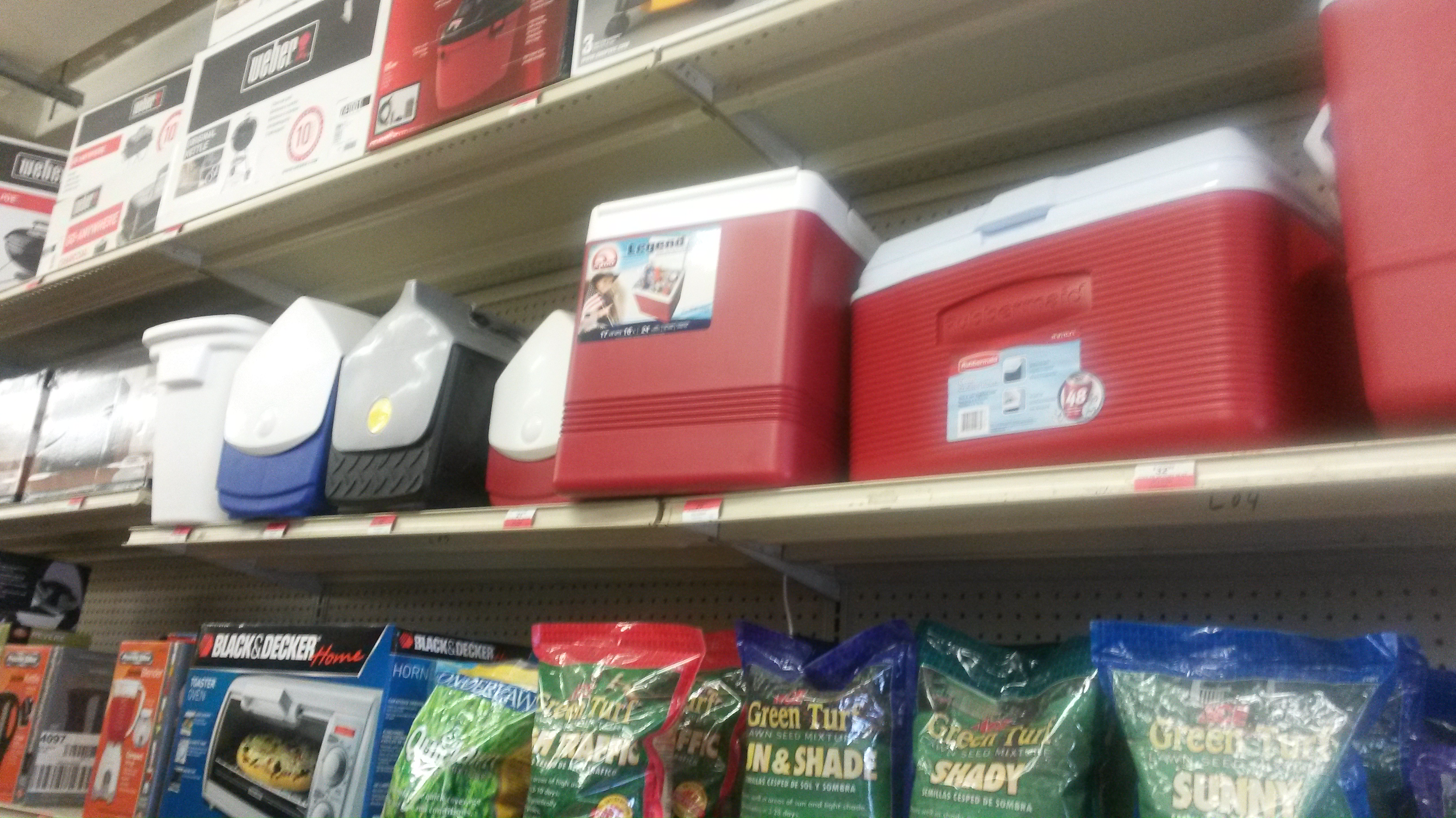
| Some cooler shopping was had, there was size giant and size non-structural-Styrofoam at the local supermarket, fortunately Sam found the 'just right' size at a local hardware store. Note, the taller the cooler the less stable the contraption will be. We were already a bit marginal on stability on the RC car frame at threat height. | 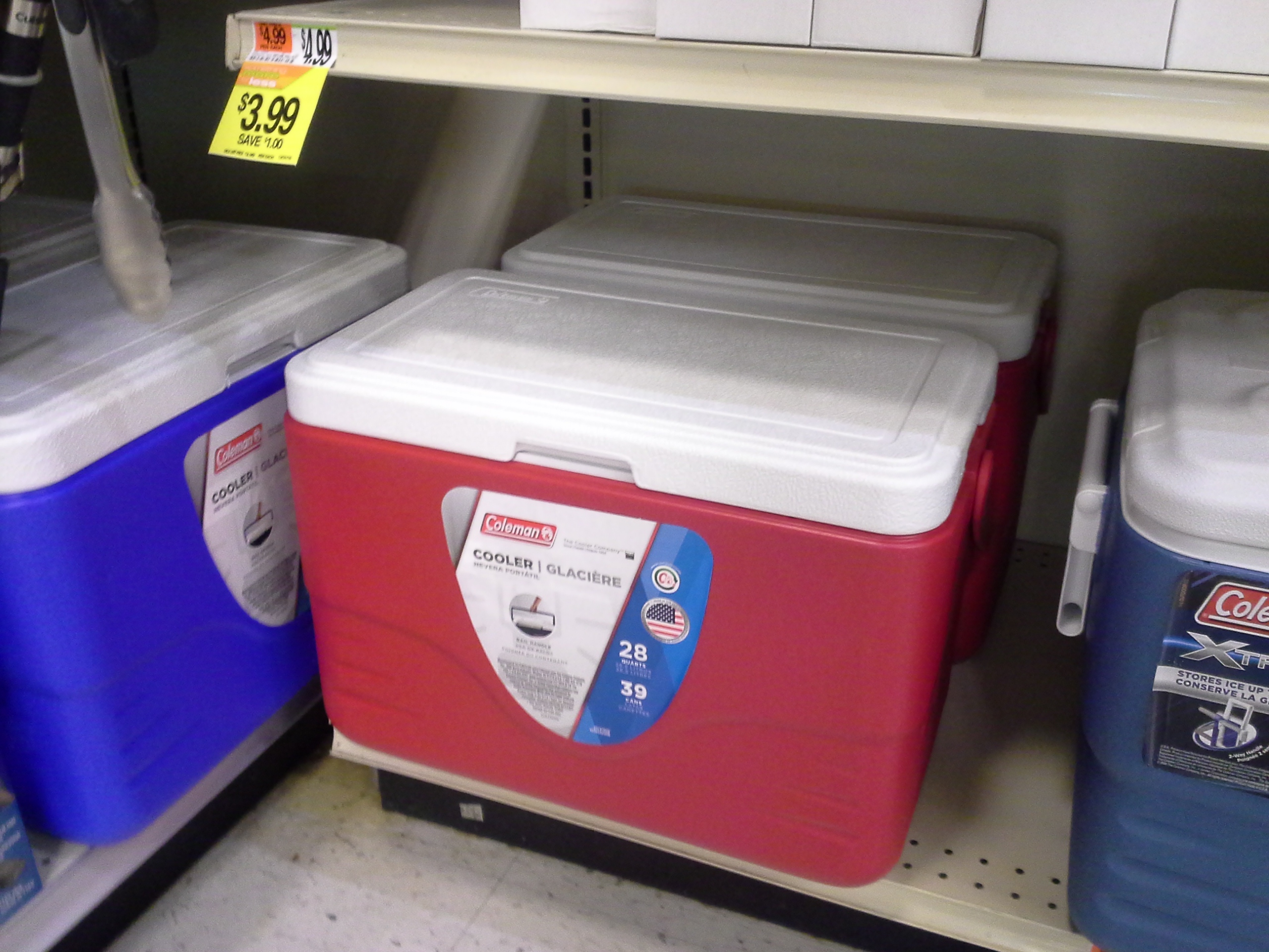 |
 |
| After some chatting and brainstorming, the following was born: a sketched-together mechanism for holding the cooler onto the RC car. The only real 'mounting' points were the 4 posts next to each wheel assembly. They are shown as holes in the drawing. |  |
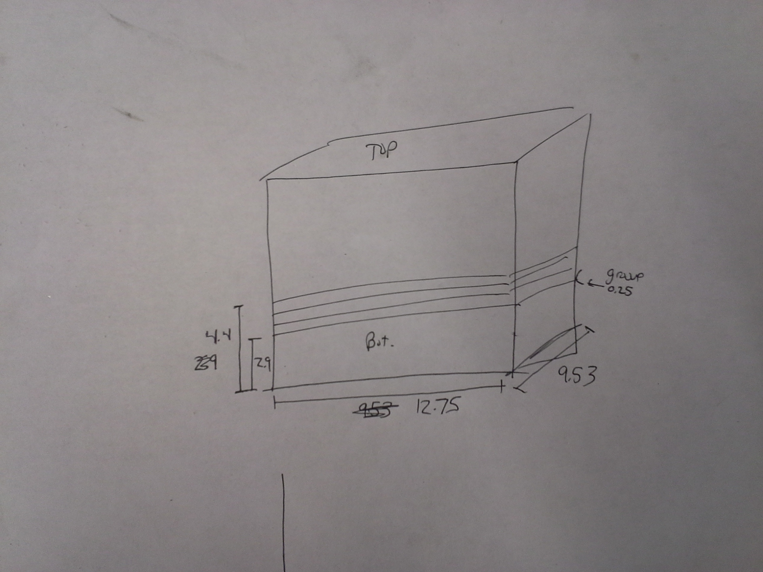 |
| Some more measurements were taken, hap-hazzardly for rough sizing. | 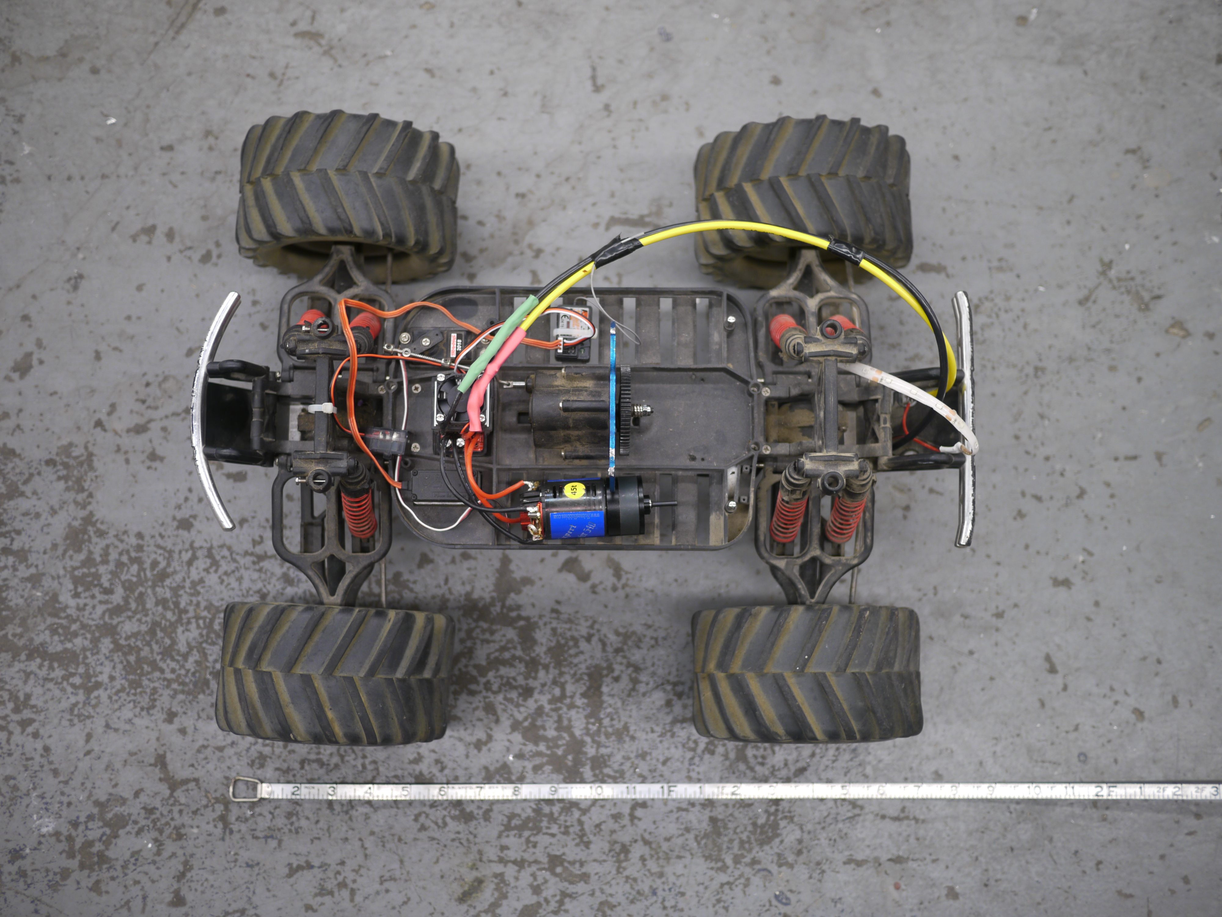 |
 |
| Some
quick observations occurred, the cart, with ~5lbs of mass applied was
very 'smushy' and sunk into its chassis pretty easily. This was an R/C
crawler and this is intentional. The options to change the
shock-absorber parameters were: * lock out the shocks * add/make new springs to compensate with the extra mass. |
 |
 |
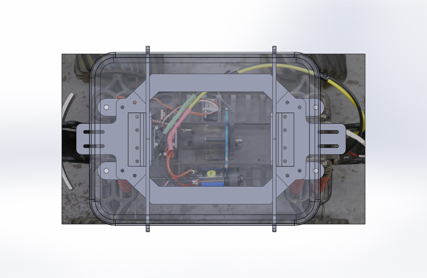
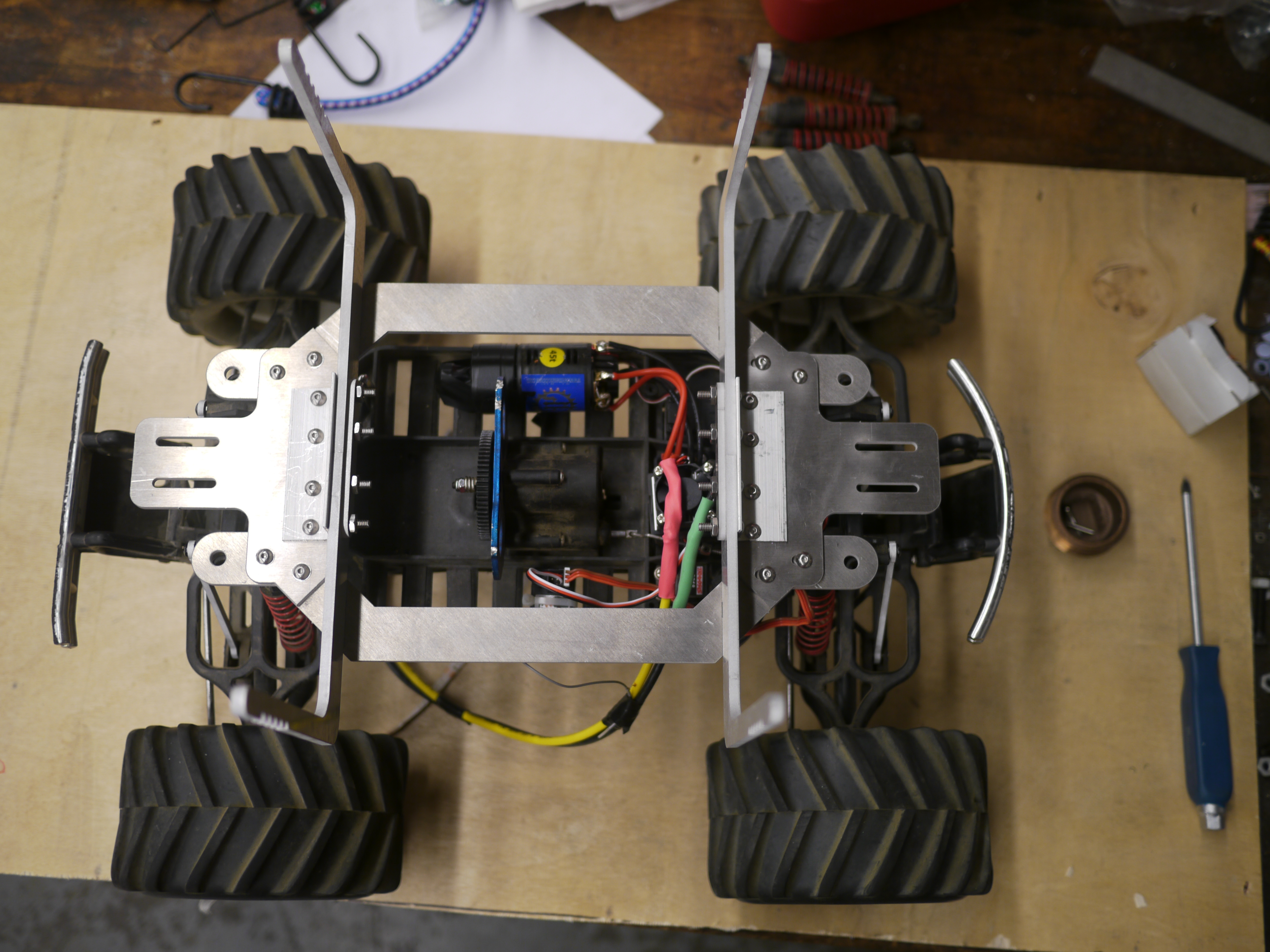
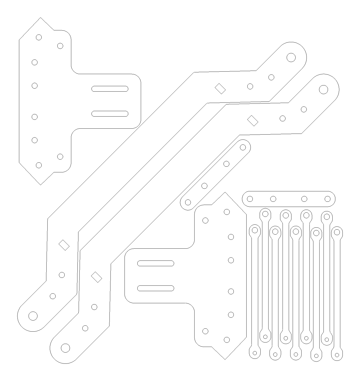
| After the quick gathering of dimensions, I scaled a top-view photo of the RC car and lined up the caliper-ed dimensions with the photo. This was incredibly useful to compensate for the gears and other hardware inside the chassis, including the motor and wiring. The cad had a second purpose, fit most of the hardware on a 12"x12" sheet of 1/8" scrap 6061 aluminum. This limited the size of some parts, and put a bit more thought into the layout. Eventually 1" x 1" angle-aluminum was used to join the uprights and the 'frame'. | 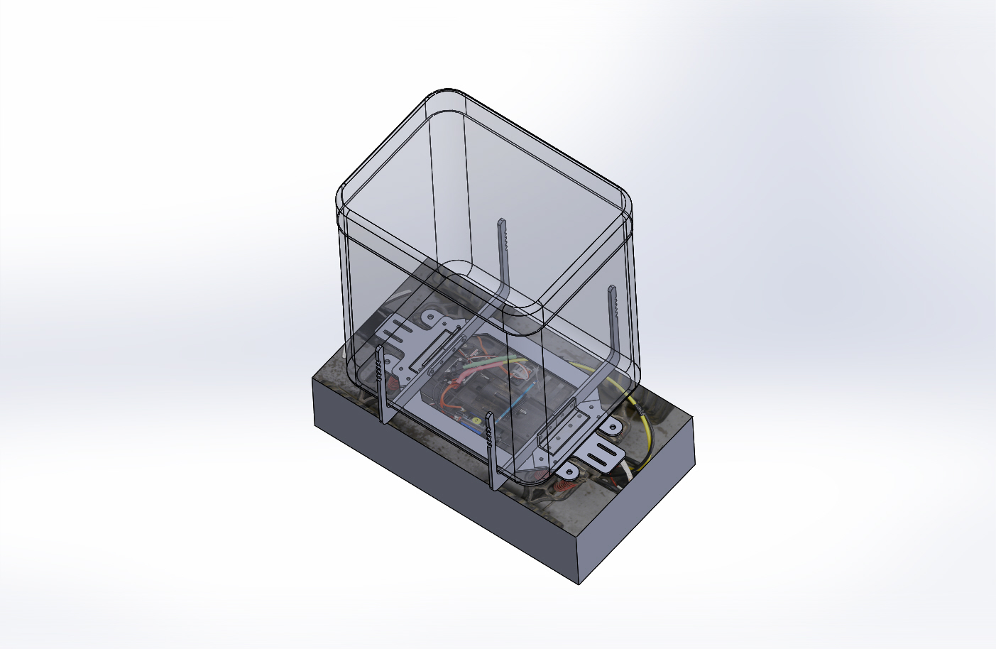 |
 |
| With the rough cad just about ready and time flying by, water jetting happened. The moons aligned and somehow the jet was open to use on a Friday afternoon. Shown right is the sub-frame including mounting points, held together with #8 screws and aluminum angle bracket. There were some issues with one of the parts, but it was fortunately repair-able with some drilled holes. | 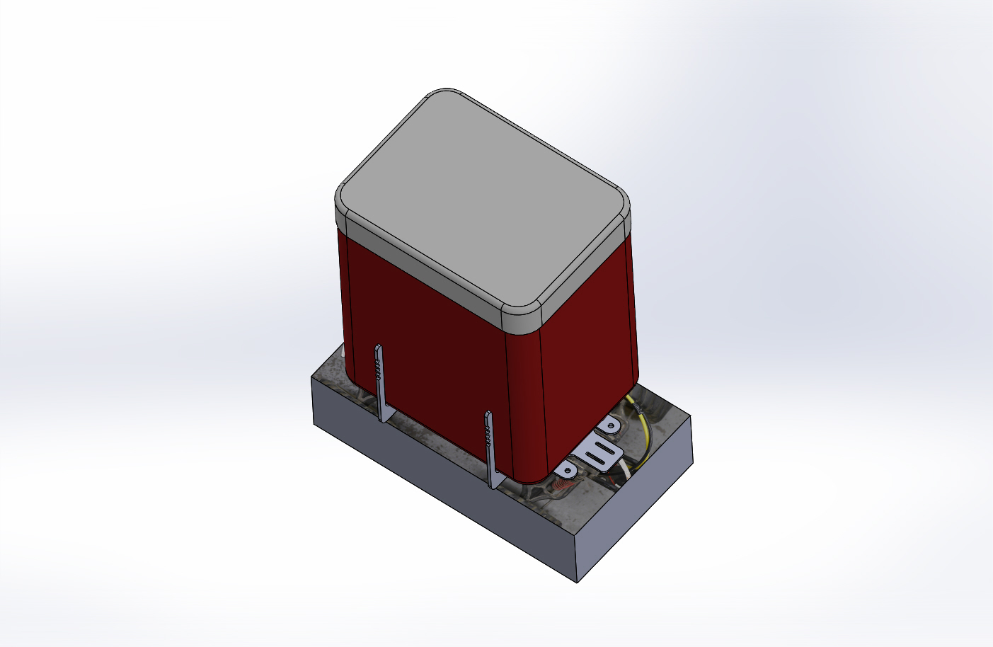 |
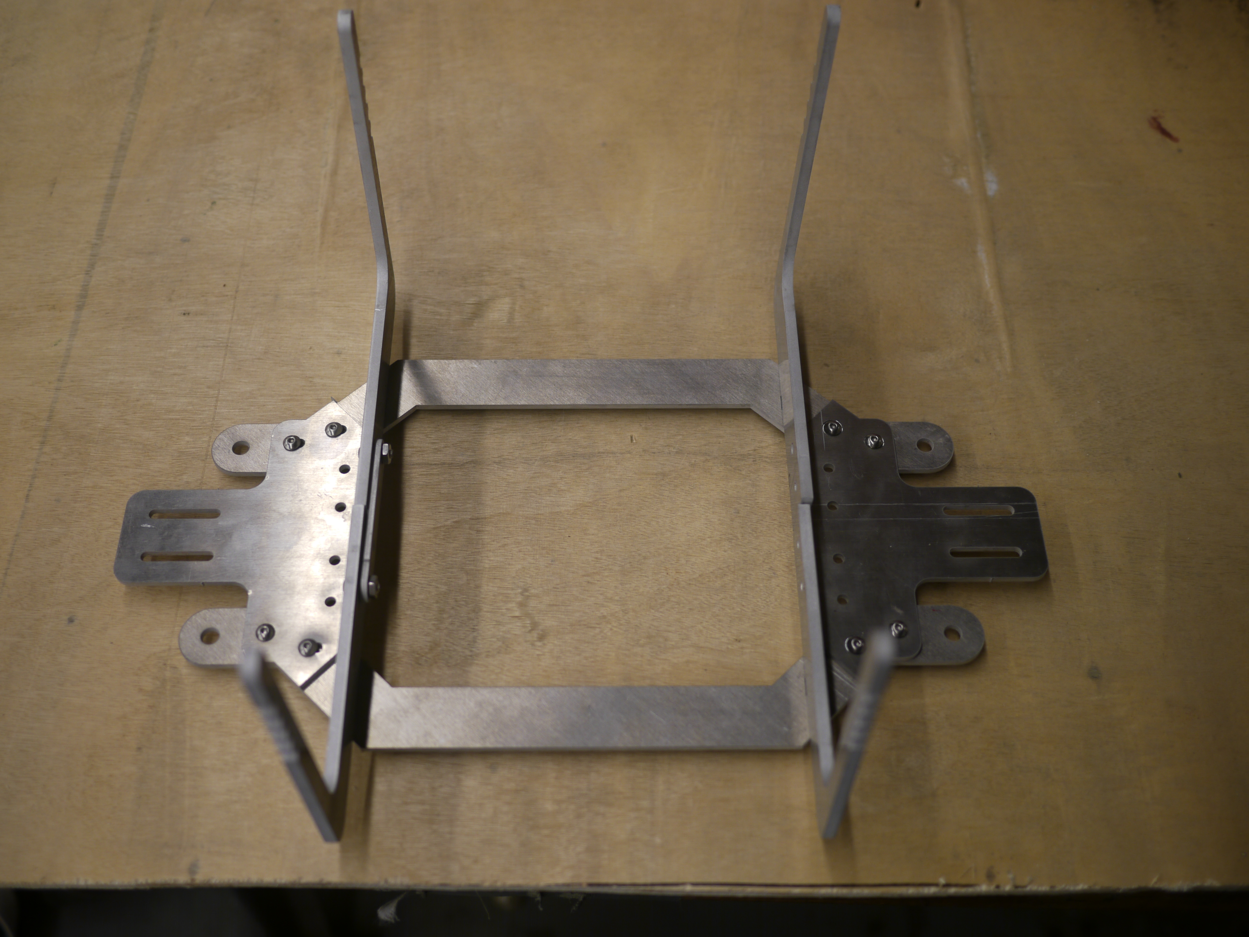 |
| The
water jet subassembly consists of four pieces, a front and back mount
with slotted groves for a sliding front cooler restraint and two long
side bars that complete the front-back mechanicals. These mate together
with two 8-32 screws. There are four water jet holes in the front /
back
plates, these allow for angle bracket to be used to mate the two
surfaces together. Shown right is the angle bracket mounted in place. Also shown is the 'shock absorber, un-absorber' plates which hold the suspension static, in the full-out position. |
 |
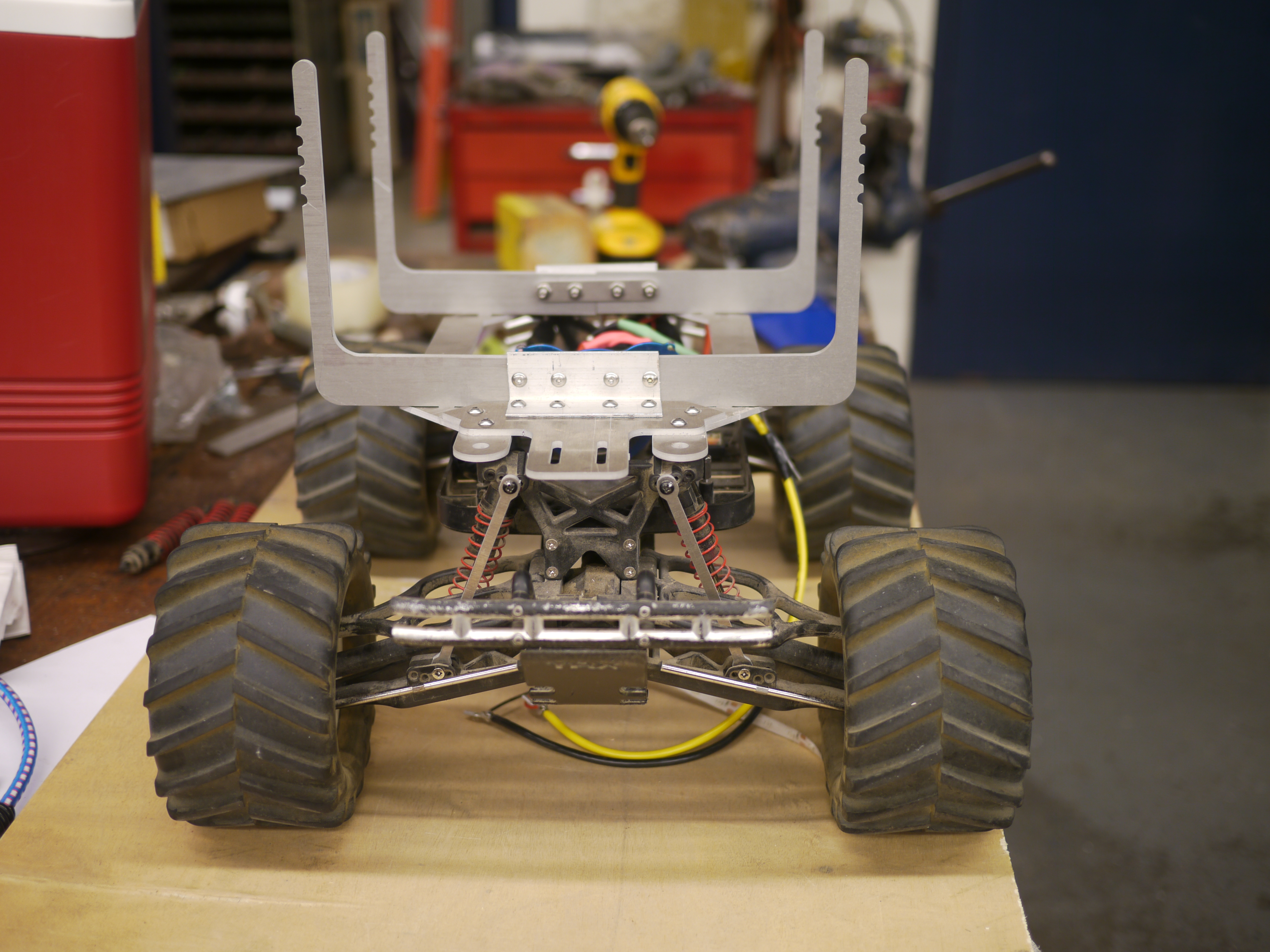 |
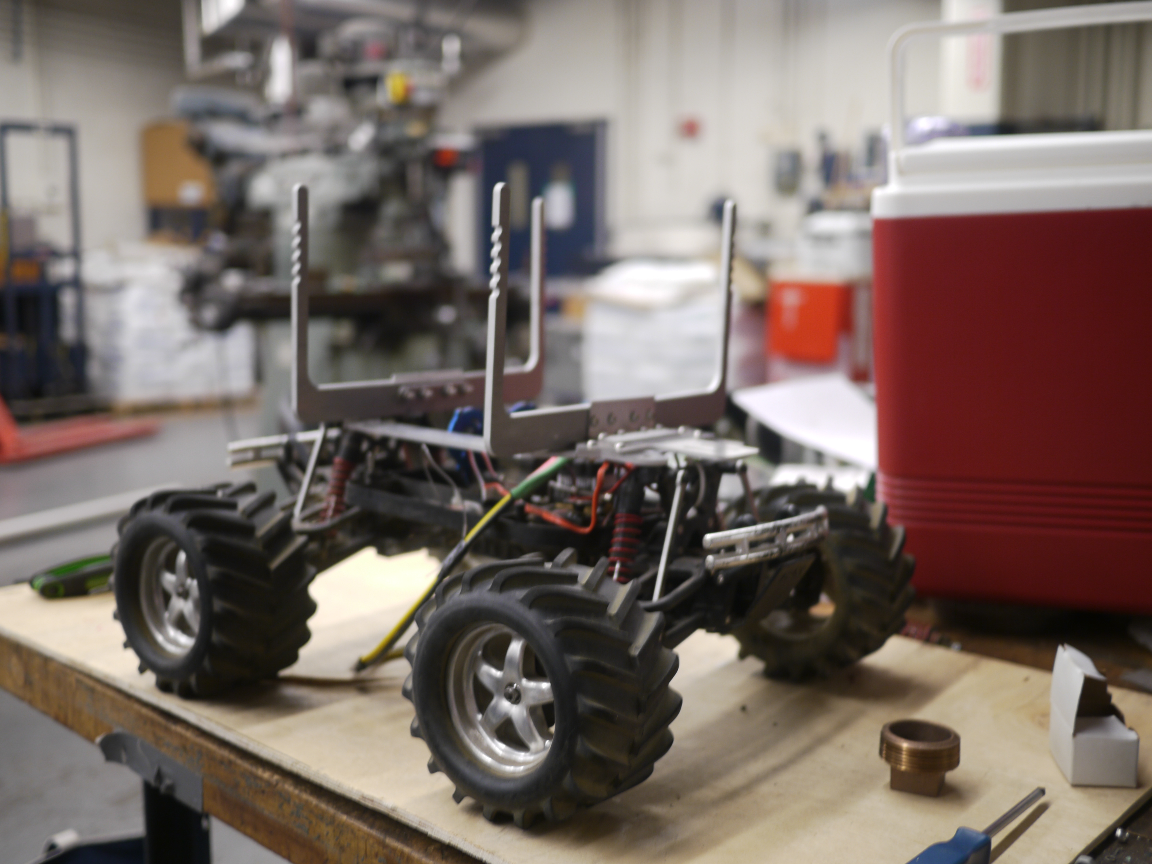
| HUZZAH
IT FITS! Somehow everything magically clears (thanks overhead photo + solidworks). There's plenty more work to do, but the mechanicals fitting is some excellent news. |
 |
 |
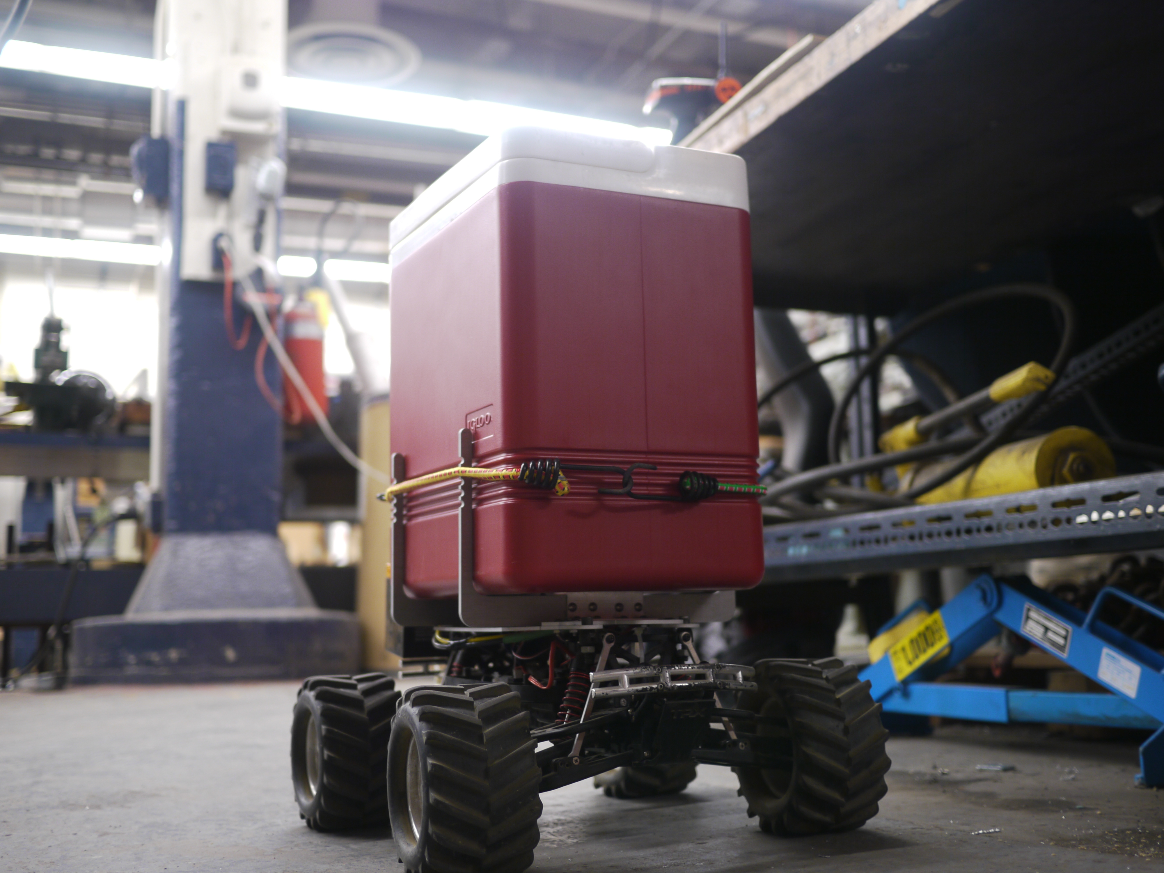
| Cooler
test fit: Excellent! the cooler fits and the ridges on the cooler line up with the ridges on the aluminum holsters. This allows for a bungee cord to wrap around and hold the cooler in place, but also allows it to be removable. |
 |
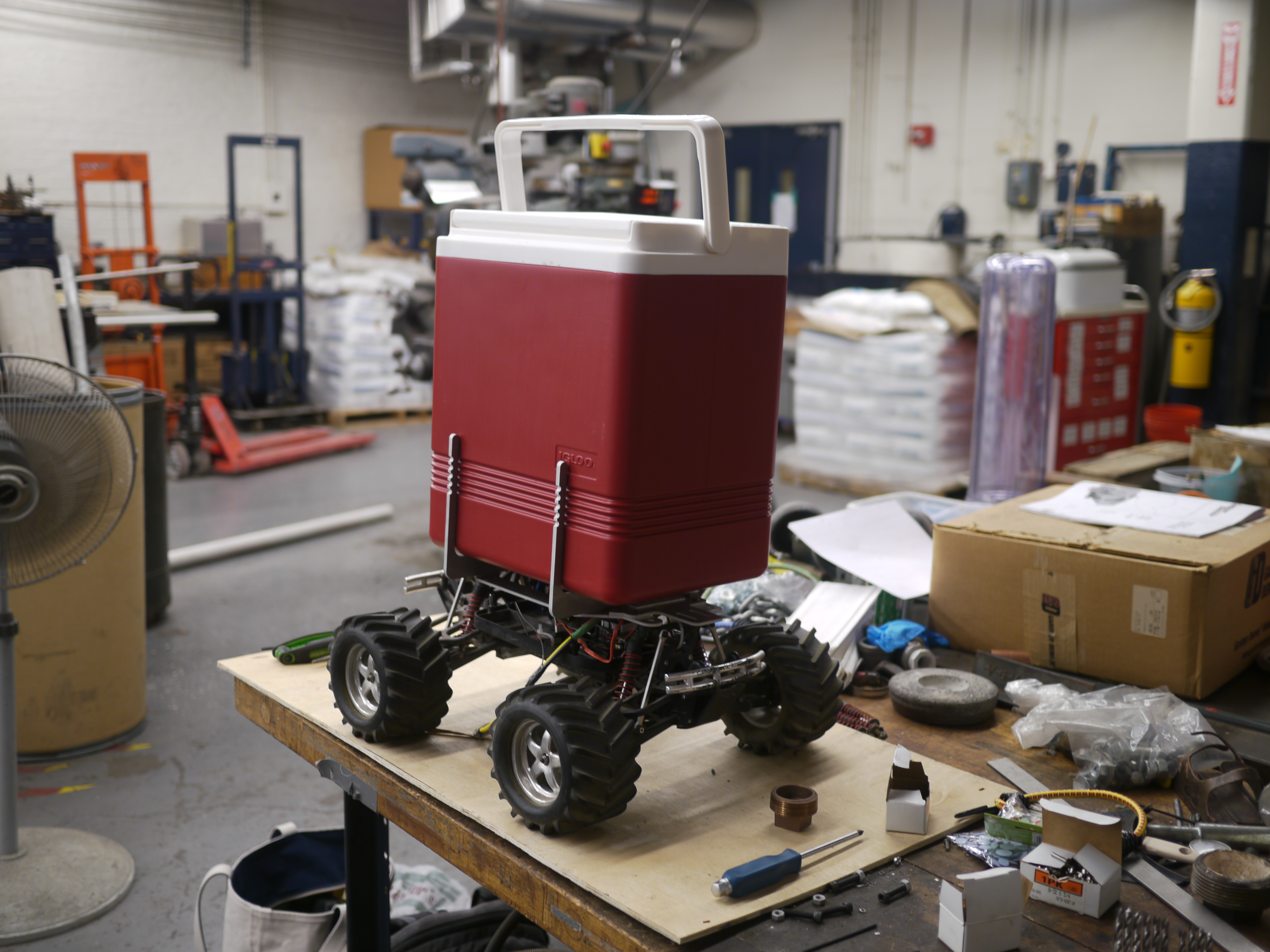 |
| It's looking like a proper contraption. Shown with bungee cords. | 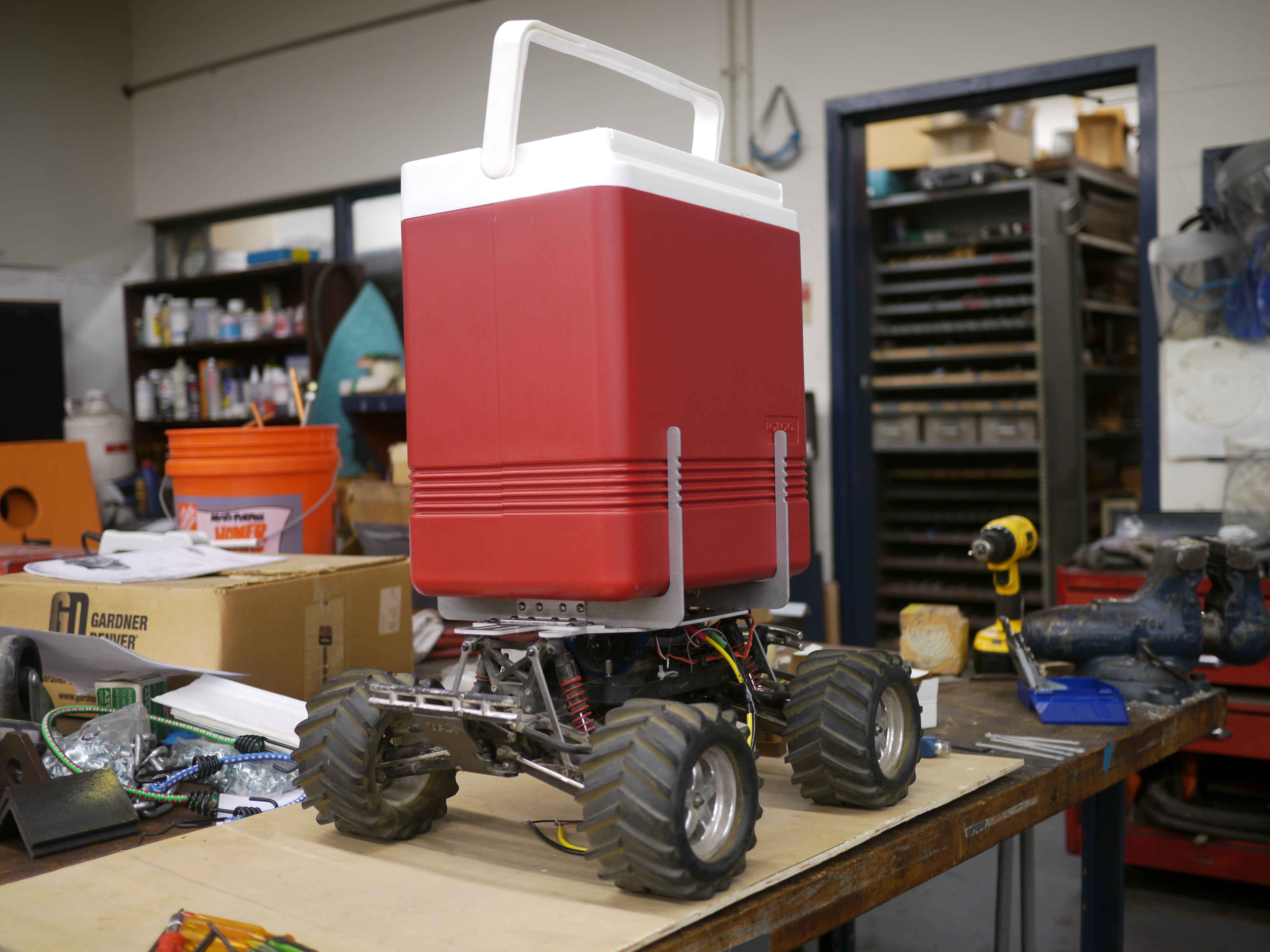 |
 |
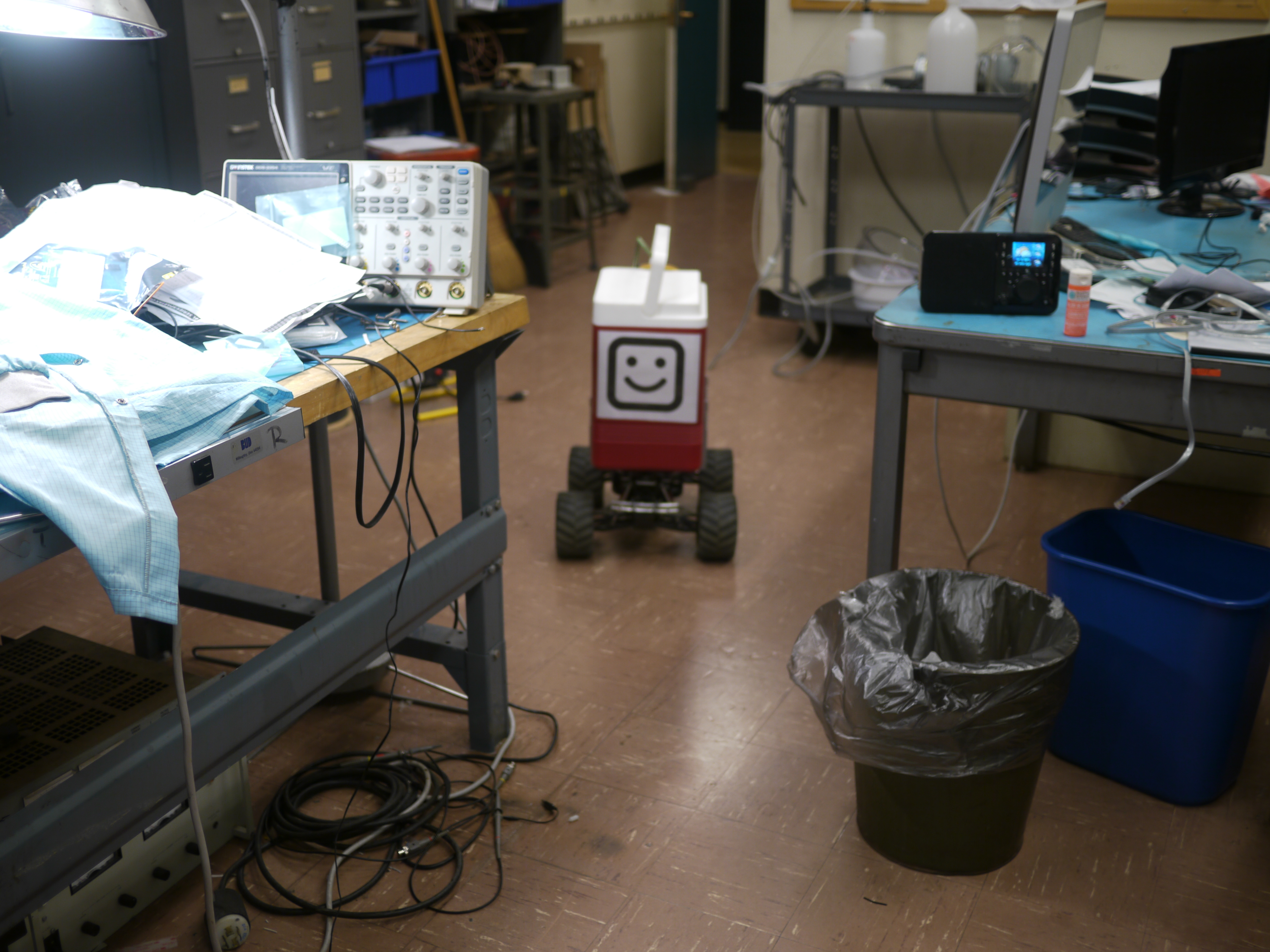
| The robot went out for a test-drive about campus, as was guessed, it was incredibly too fast. There were a number of attempts at keeping it 'reasonable', but it was quite a bit of fun testing how fast it could travel without flipping over. It also needed a more reasonable visage, and lo, smiley robot. | 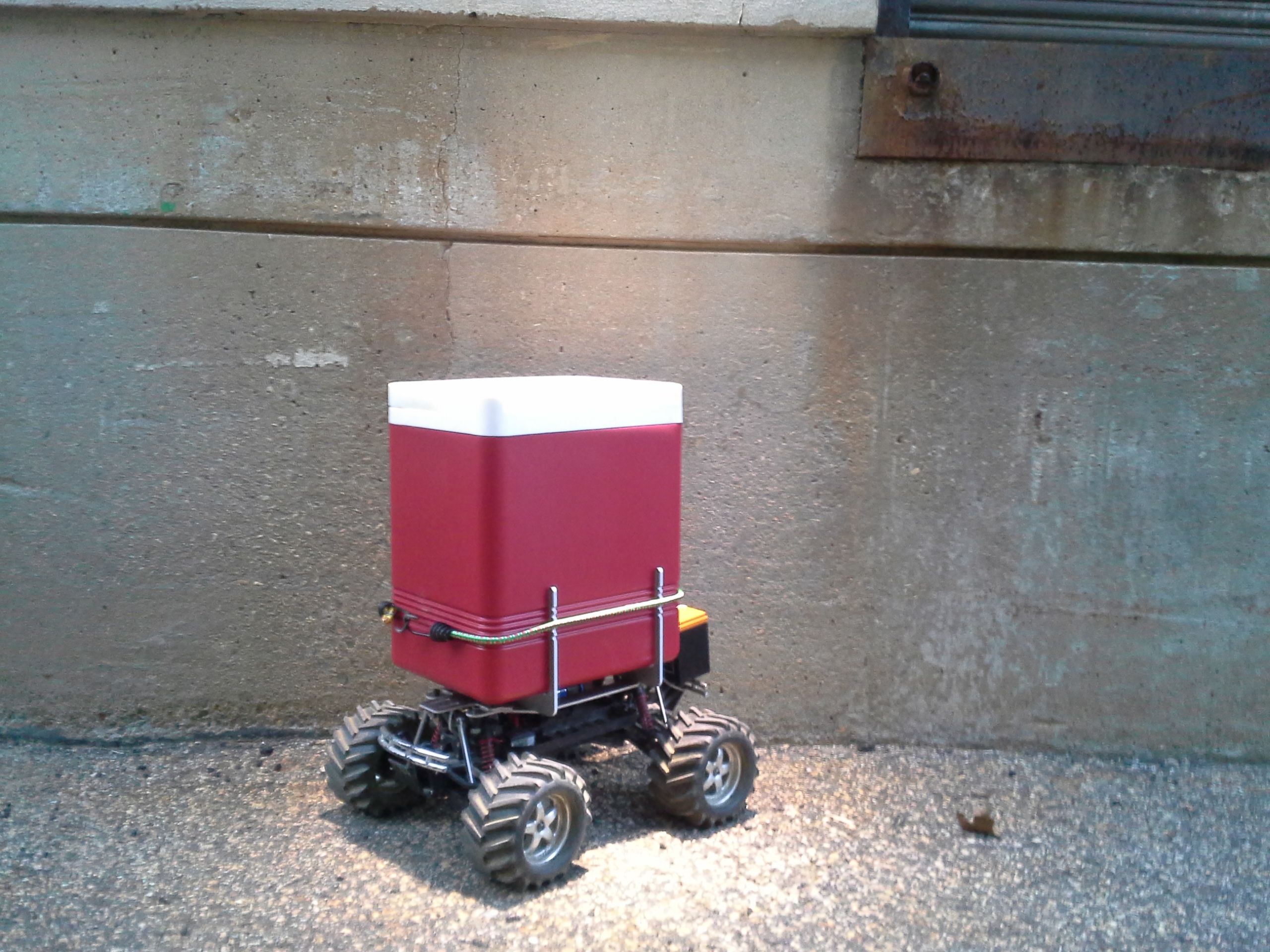 |
 |
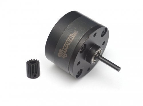
| Planetary
gearboxes ahoy Given the propensity for the bot to flip about, due to relatively high top-speed even in low-gear, a 3:1 reduction box was used. This fit continently in-line with the 540 motor and worked perfectly to bring the contraption down to walking-speed. The motor was really zooming to keep up, but it overall worked really well. Available from asiatees [link] or amazon [link]. |
 |
 |
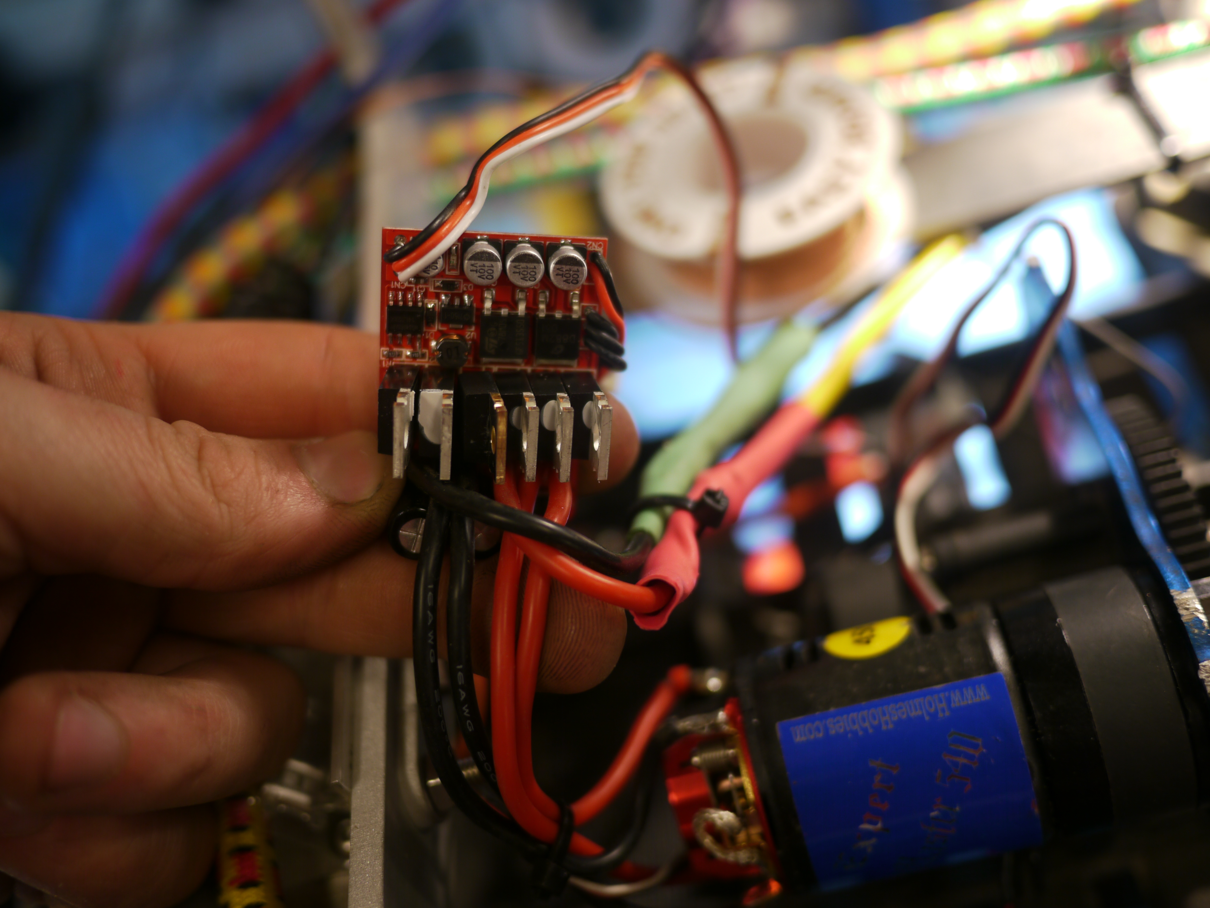
| Whats
running this contraption? The power source is an ALM 12V7, 5ah LiFePO4 battery pack, at 13.4v, and the motor controller is a UNIK 320A High Voltage Speed controller [link]. On the eve of the trip to Red Fire Farms, the controller emitted magical smoke and sadness, unfortunately at ~1AM. As it turned out one of the mosfets failed, and thanks to my trusty thermal-camera it was fairly easy to pick out the culprit. I swapped in the closest fet I had on hand, and somehow the contraption woke back up and was ready for a day of adventure. Curious controller topology, stacked fets smushed in between a heat sink. |
 |
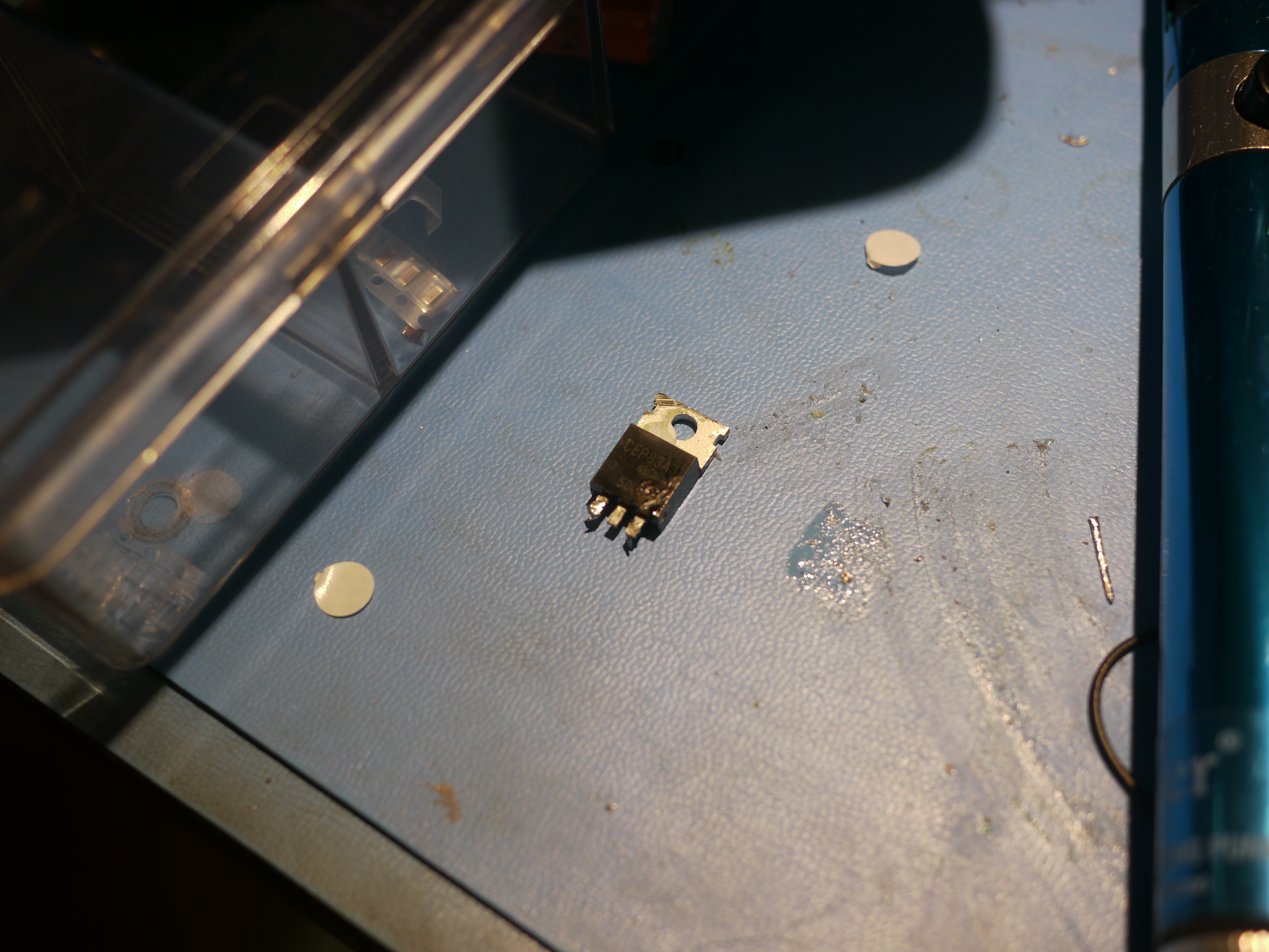 |
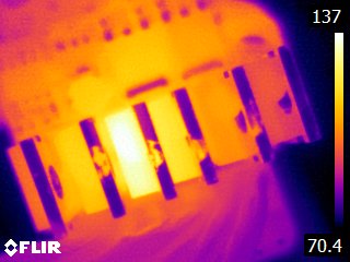
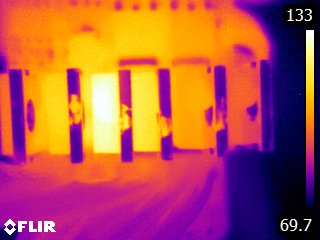
| Flir
capture of the 'hot' fets Note the fets are stacked next to each other and an aluminum heat sink sits coupled to the fins of the fets via an over molded insert. The glowing fet (3rd from left) was the culprit, Nchannel 30V low RDSon mosfet. After swapping with a relatively high voltage, higher rdson fet, it appeared to come back to life, just in time. |
 |
 |
| Early Testing | |
| The RC car chassis was outfitted with an LED strip and the first test drive happened. This was deemed waaaaay too fast | |
| After installing a 3:1 planetary reduction, the contraption was tested again, this time with the cooler attached. A simulated weight was added to the cooler, consisting of a large quantity of manila folders. It was more reasonable for a top speed, but the increased torque resulted in a number of high-acceleration flip overs | |
| Yeah
it's really good at flipping over. As a note, a 2 Channel receiver/transmitter was used to control the contraption [link] |
| Field Testing, In a field |
||
| The weather was fantastic, Sam couldnt quite have picked a better place or day, well worth the trip! I tagged along with Sam, Peter and Reyu and gleaned some strawberry-picking technique as well as what types of berries to pick. |  |
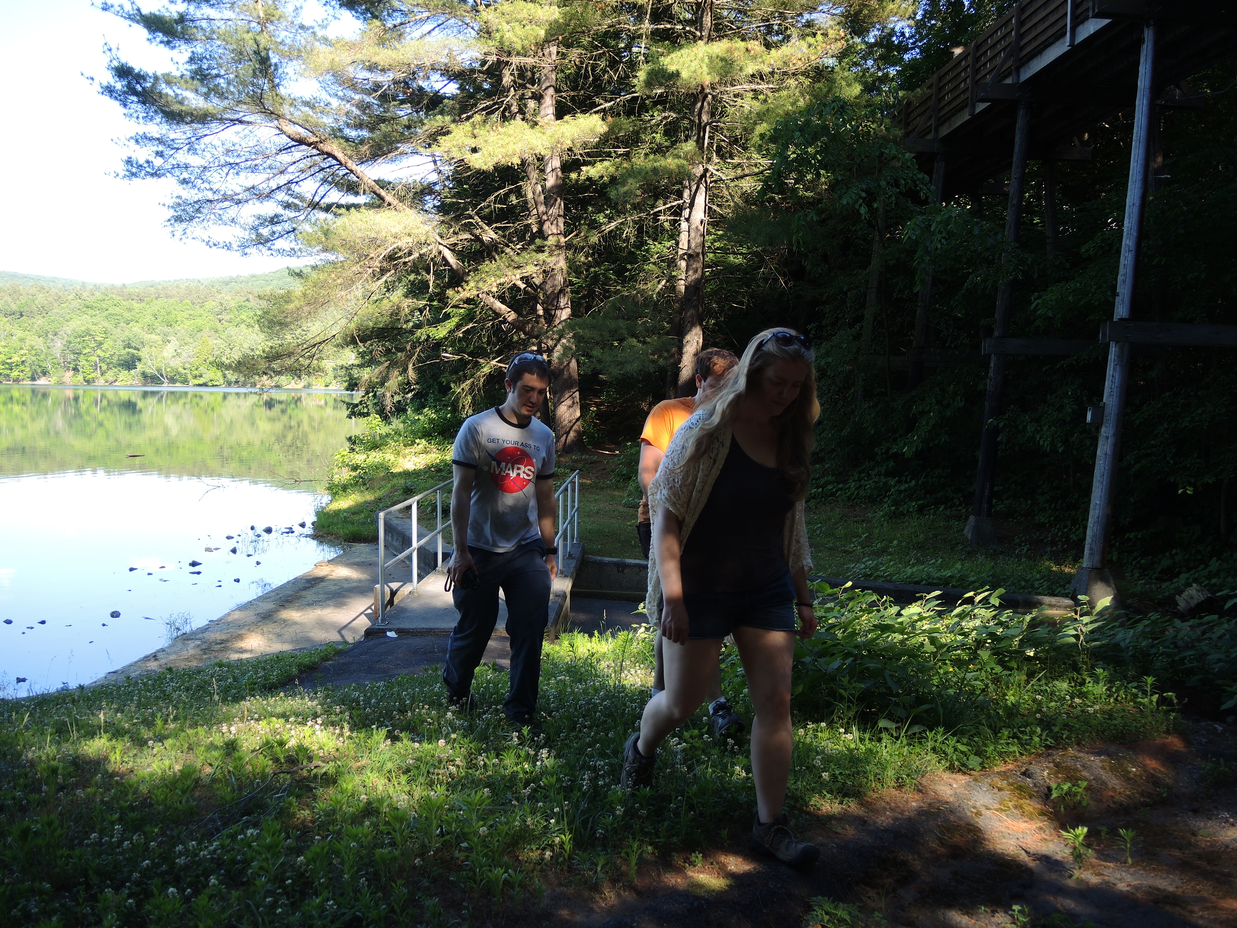 |
| The day was beautiful, and the berries were delicious. Admittedly, I had never had 'fresh' strawberries before, I'm not sure where the grocery-store berries appear from. These were delicious, unbelievably delicious. | 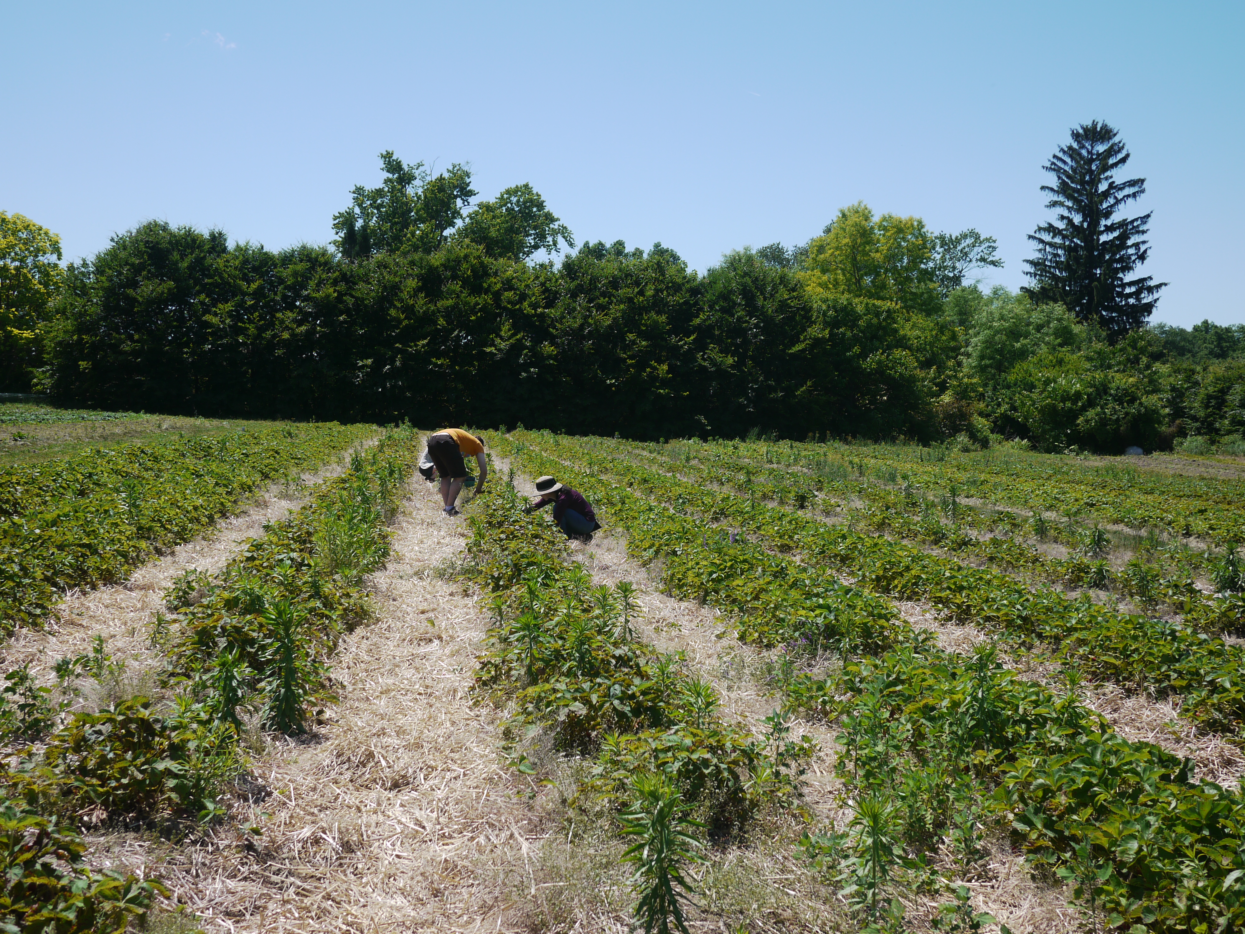 |
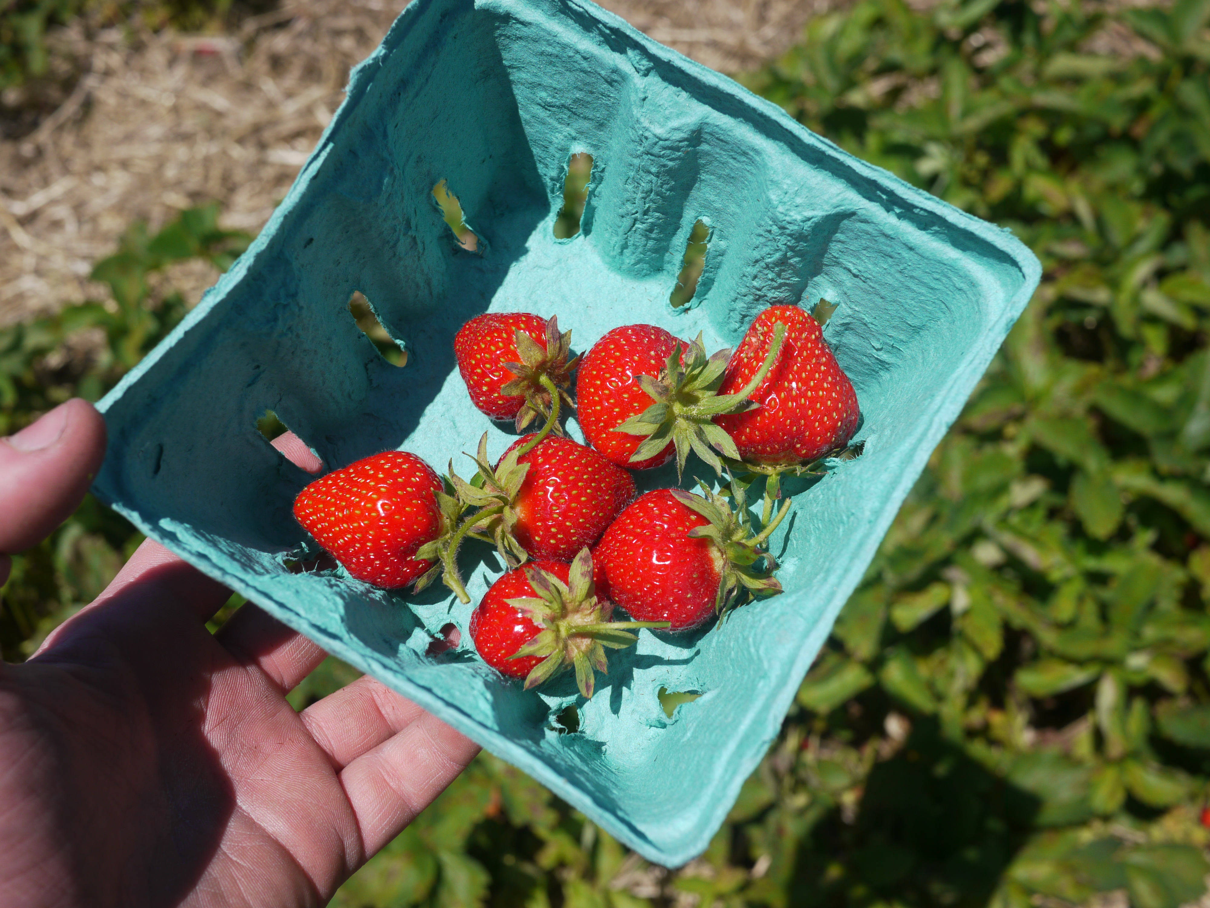 |
| After our boxes of berries started to fill, a contraption was driven over to carry them about, in a 'cooled' fashion. | 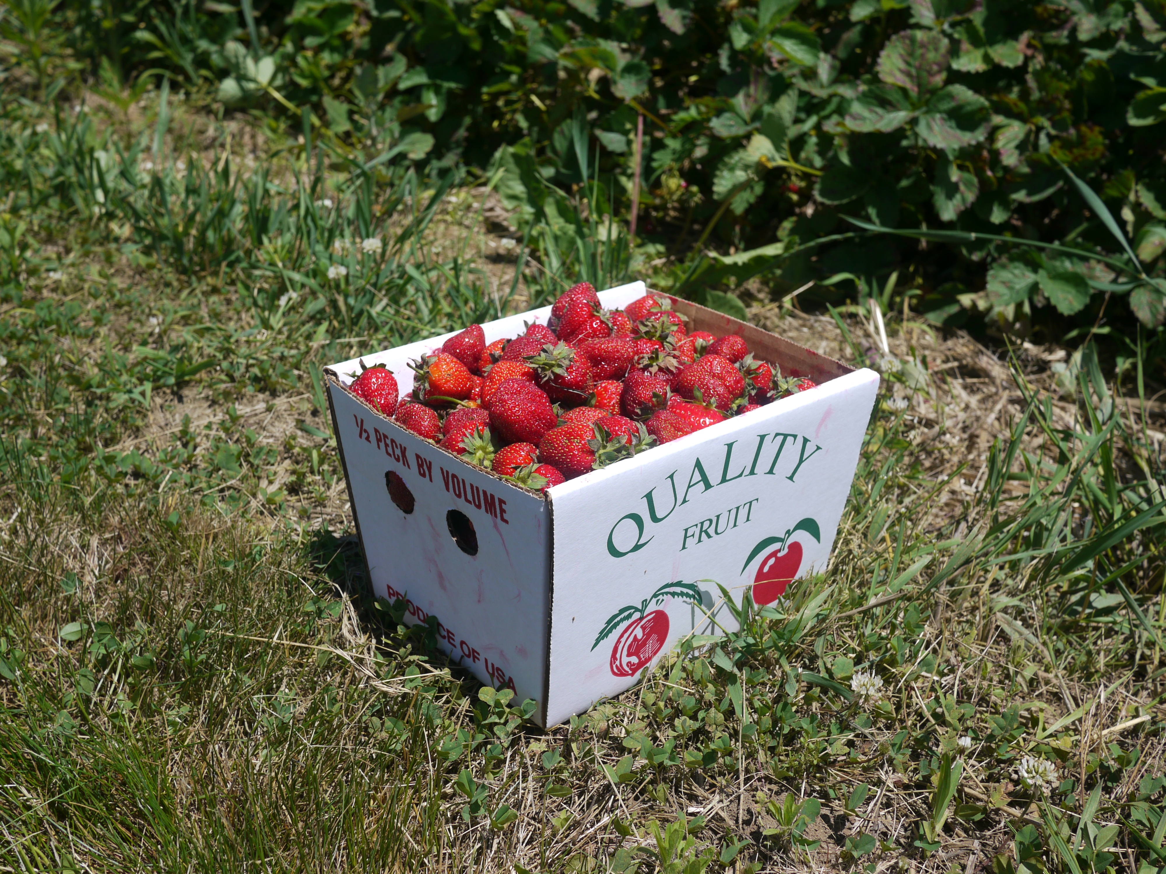 |
|
| Like anything the robot got into trouble and flipped over, 'overturning' its insides a few times, but it did make a great companion and test of driving skills. | 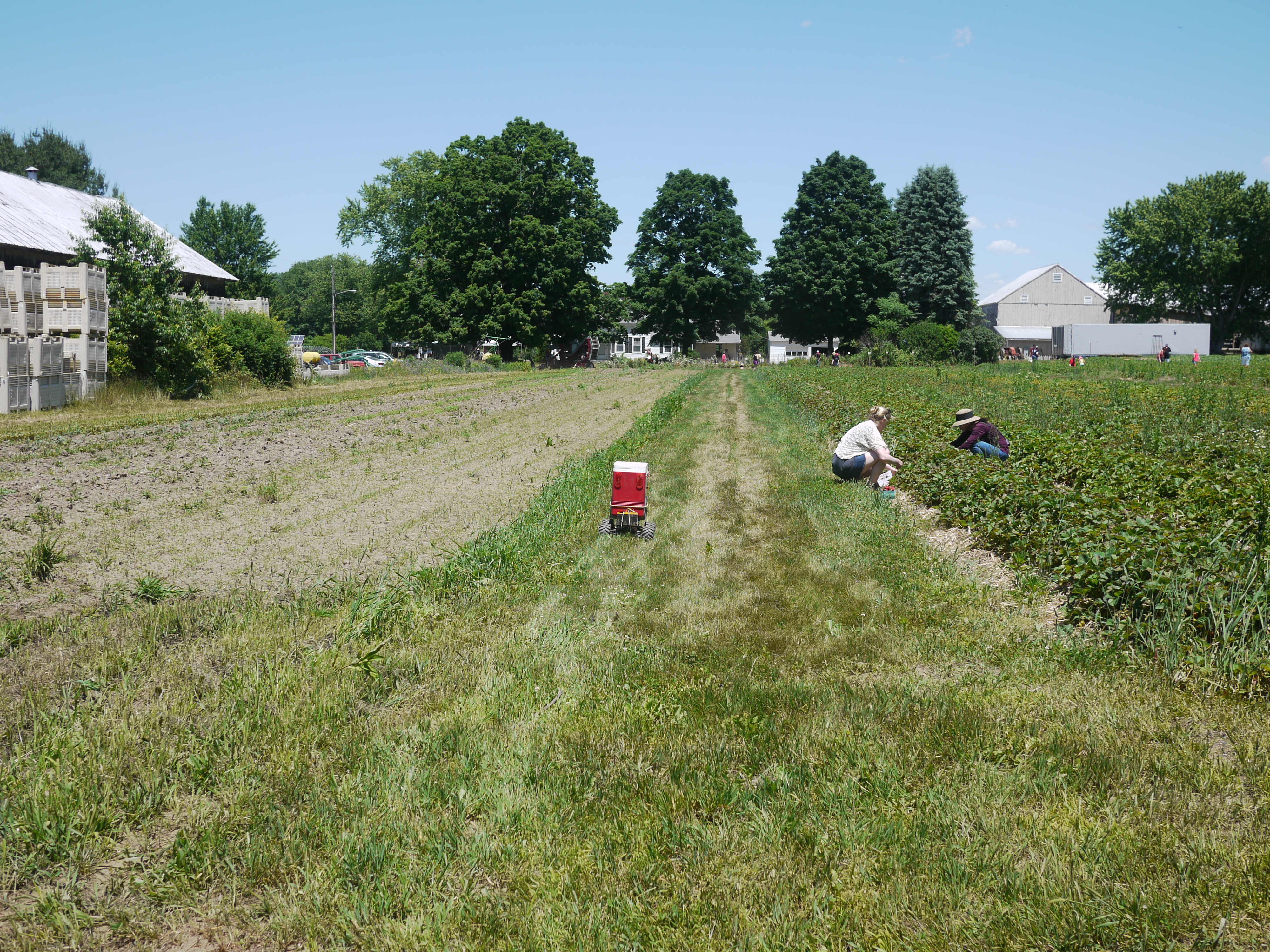 |
 |
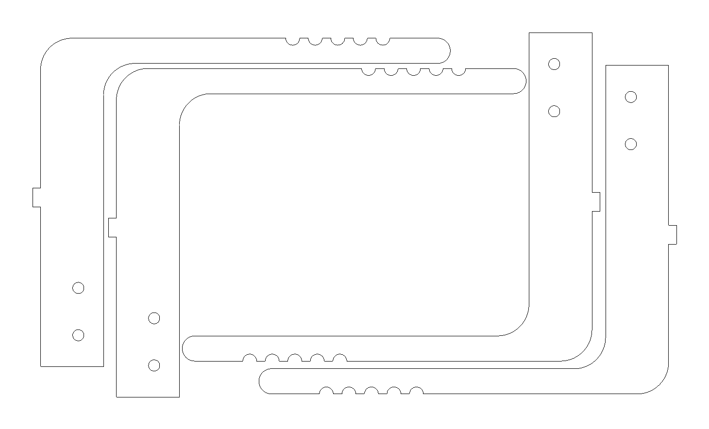
| Design files! | ||
| Design
files for the whole robot are contained in a pack&go zip,
solidworks 2014 [link].
The design files are setup for two sheets, one 12in x 12in 0.125" thick
aluminum sheet and one, scrap, 0.196" sheet of aluminum, roughly 8" x
4" in size. What if you dont have a waterjet? submit the
files to
bigbluesaw [link],
cut them out with a jigsaw, using thin plywood, or lasercut acrylic
sheet! DXF files are scaled in US units, printing on 11x17 paper and
tracing onto wood / plastic sheet works just as well! The DXF's for the cuts are here 0.125" [dxf] 0.196" [dxf] |
 |
 |
| Steps Forward, follow-along mode | |
| Carrying around an RC controller is nice, but wouldnt it be neat if the robot could just follow along and take care of itself? This isnt quite an easy problem to solve, curiously, lets take a look at to other projects that try and solve this problem. | |
| The first project that I looked at is here [link], its a well detailed, and uses a mix of sensors to try and solve the problem of a following robot. A beacon is carried around and an array of ultrasonic receivers are used to triangulate the beacon. A small IR range finder is used for obstacle avoidance. This seems like the best option for short-range position sensing & following, outdoors it may run into issues with obstacle avoidance (lots of IR light, soft objects in the way of the contraption) | 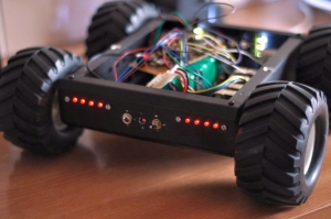 |
| Using a mobile phone as a beacon would be a swanky way to have an easily available beacon, the paper "localization of wireless sensor networks with a mobile beacon" [link] [local link] actually goes into how this can be achieved. The long story short, localization is non-trivial. The route taken is to evaluate RSSI ranging, which, seems to work well with coarse accuracy. I like it. The paper is a bit over a decade old, and i'm curious to see how I can improve upon the findings. Opting for multiple receivers based on RSSI and their collective ratio metric RSSI could be used to improve upon this. To do this in a simple fashion, multiple BLE UART shields [link] could be used. Each shield, based around the NRF51822, already outputs RSSI when queried, and multiple units arranged in a pattern about the robot could be used to ascertain position. Changing the default antennas to SMA connectors with OMNI antennas could help correct any horizontal / vertical polarization issues. | 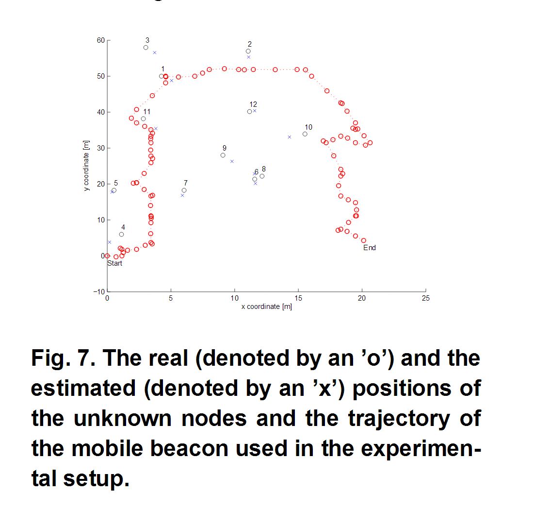 |
(There's
other photos in the photo
gallery)
Concluding Remarks:- Strawberry bot gleaned a number of smiles on a very sunny happy day, there's a lot of room for upgrades. An accelerometer could be used to govern the craft's speed and 'tipsyness', bluetooth 'follow-me' could be implemented to reduce the amount of external controls required to operate, etc. A peltier-cooled fridge was evaluated, but deemed uncessary, as the coolers that were investigated were ~20w and required significant cooldown times, whereas ice-packs did the job fairly well without extra hassle.
- Cant than Red Fire Farm enough for the wonderful day and excellent experience, and Sam for finding this excellent place.
| Comments: |
|
HTML Comment Box
is loading comments...
|
(be
careful, im not responsible for your freshly smushed fruits/vegetables)
Dane.Kouttron
Rensselaer Polytechnic Institute
Electrical & Electrical Power
631.978.1650
