
Dane Kouttron
Project Documentation: 06/2016 Reformatted: 01/2024
Armor X7 Teardown & Battery Upgrade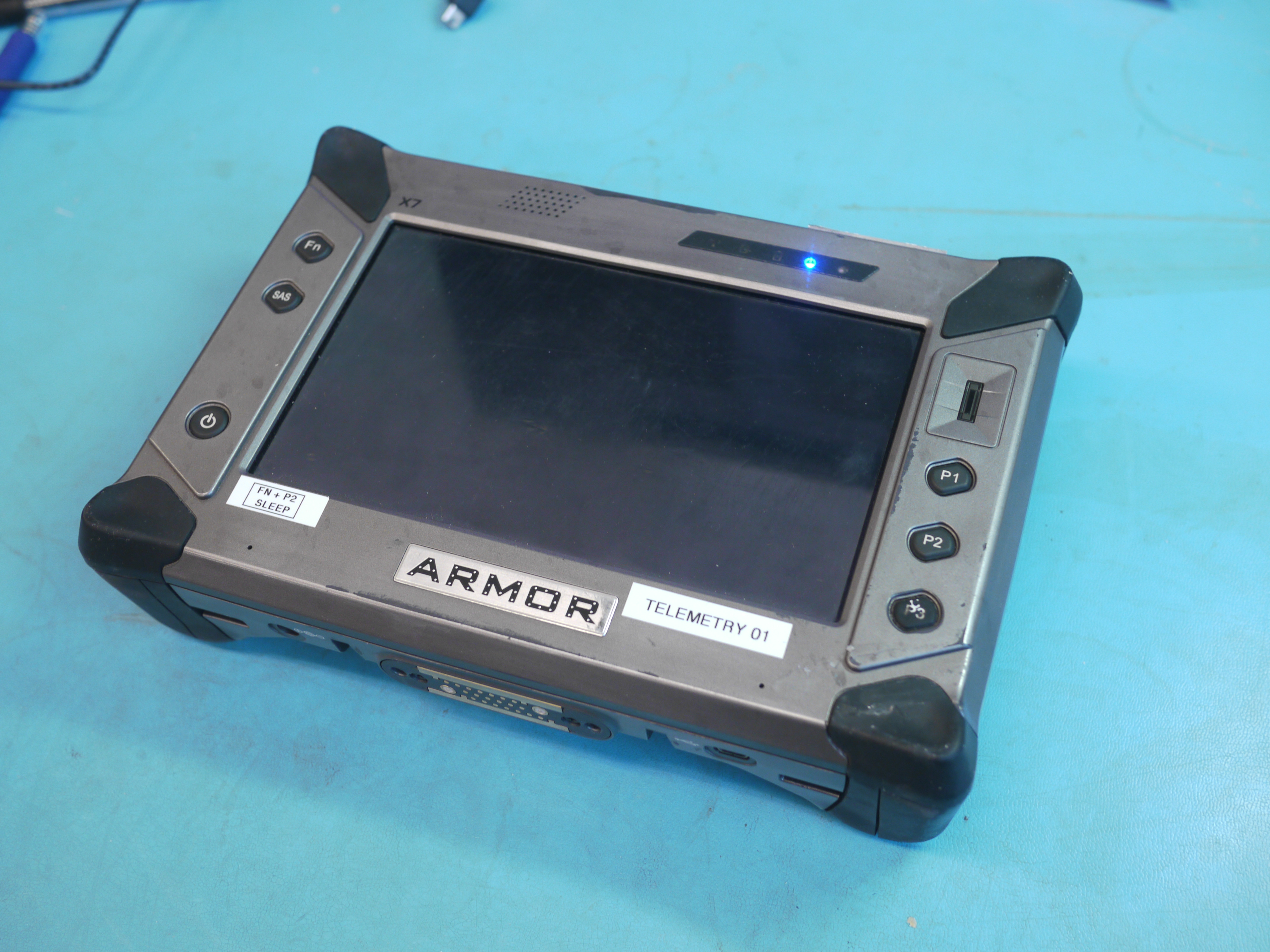

The Armor X7 is a ruggedized tablet, with some impressive specs. Its MIL-STD-810F rated for vibration, its IP65 rated for dust and water and really really sturdy, it features a resistive + capacitive touchscreen and is great for data logging or outdoor science. Here's an overview of specs [pdf]. I wanted to investigate the internal hardware and throw together an upgraded battery module to enable some extended outdoor science. The X7 was born ~5 yrs ago and for some reason a pile of them appeared on ebay for $40 each, I grabbed a few and went to work on making custom battery packs and custom modular modems to live in the flexspace battery connector. |
What? More details please!The X7 features two hot-swappable battery packs. There are two configurations for the battery packs, two cell (2x 2950mAh cells in series), or four cell (2x 2950mAh cells in series and 2 in parallel). Each of the 2-cell packs can run the unit for a little under 1.5 hrs. CURIOUSLY, one side of the X7 features a connector for adding custom peripherals. The connector [flexspace] has extra USB available [link to flexspace manual]. This is great for adding a Bluetooth Low energy / xbee / whatever external hardware, in a removable fashion. Ideally the left battery pack would be a 4 cell (3 hrs of runtime) and the right pack would be a module that used the flexspace connector for connecting a DIY module. 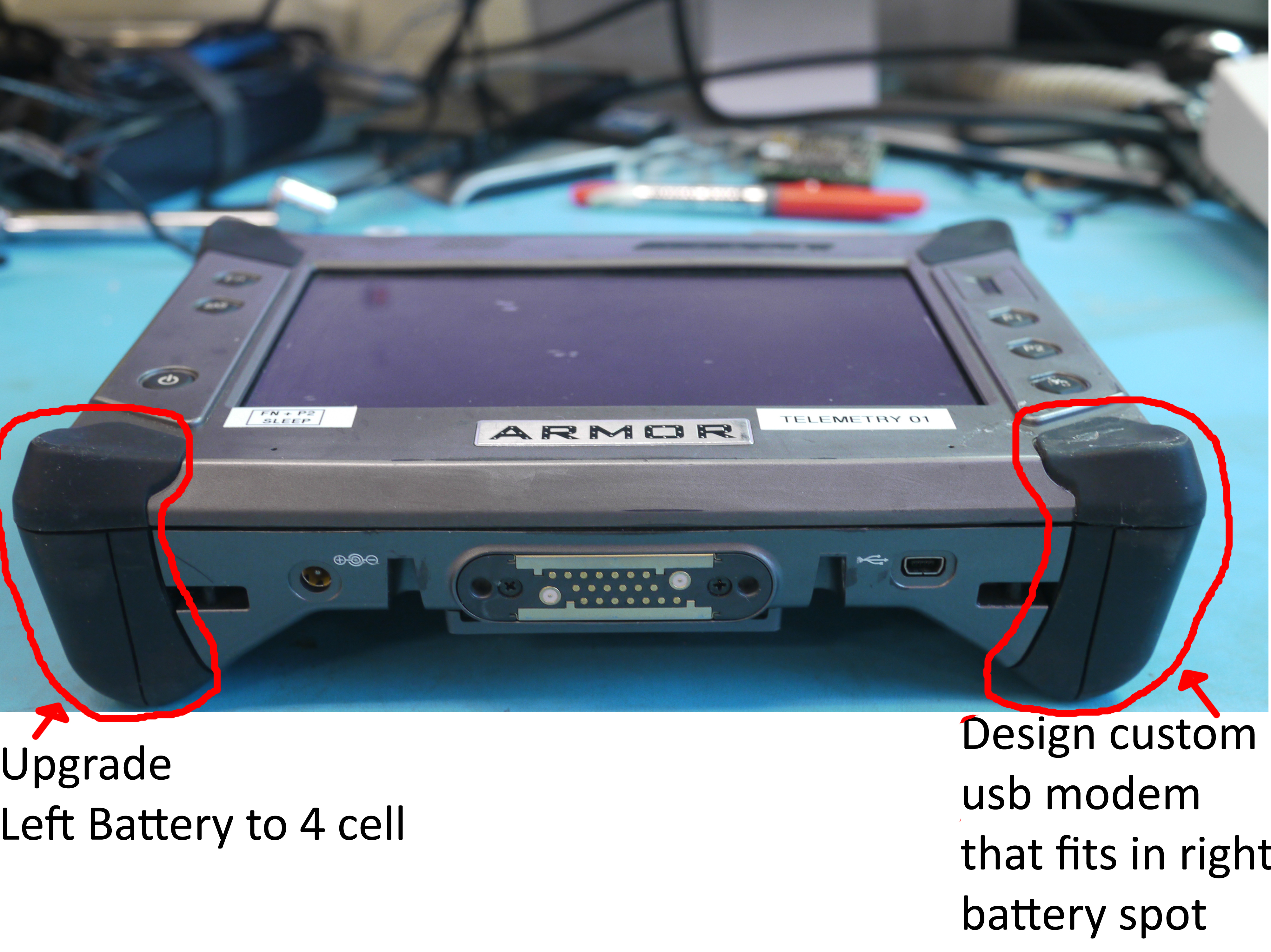
Battery Teardown and DebuggingThe armor X7 has two removable battery modules that live along the side of the tablet, they are hot-swappable, and connect via a spring-loaded pogo-pin esque connector. The battery side is static and the tablet side has the spring-loaded connector. The batterys are swappable, an internal windows utility can allocate which one is preferred to charge first. 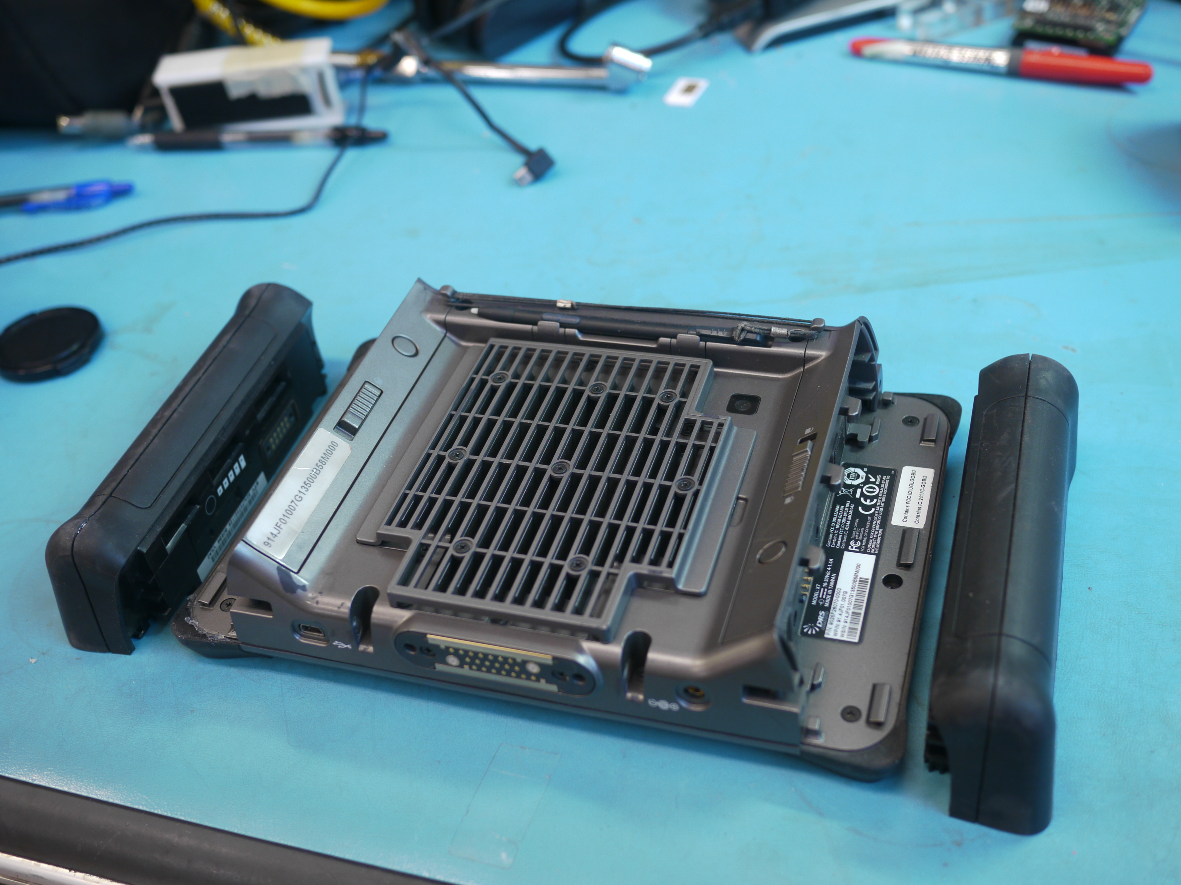
As a quick test and demo, I fired up ARMOR UTILS, a built in x86 application to check on any battery telemetry. The stock pack is 2.95Ah new, and they have only seen 44 cycles, not bad! Stubby rubber bumpers are included around the front face to limit damage from impacts. There's a fingerprint scanner, which I havent poked at and five hardware pushbuttons. Interestingly 'P3' appears to be enter (in startup selection circumstances) and 'P1' / 'P2' appear to be up/down. 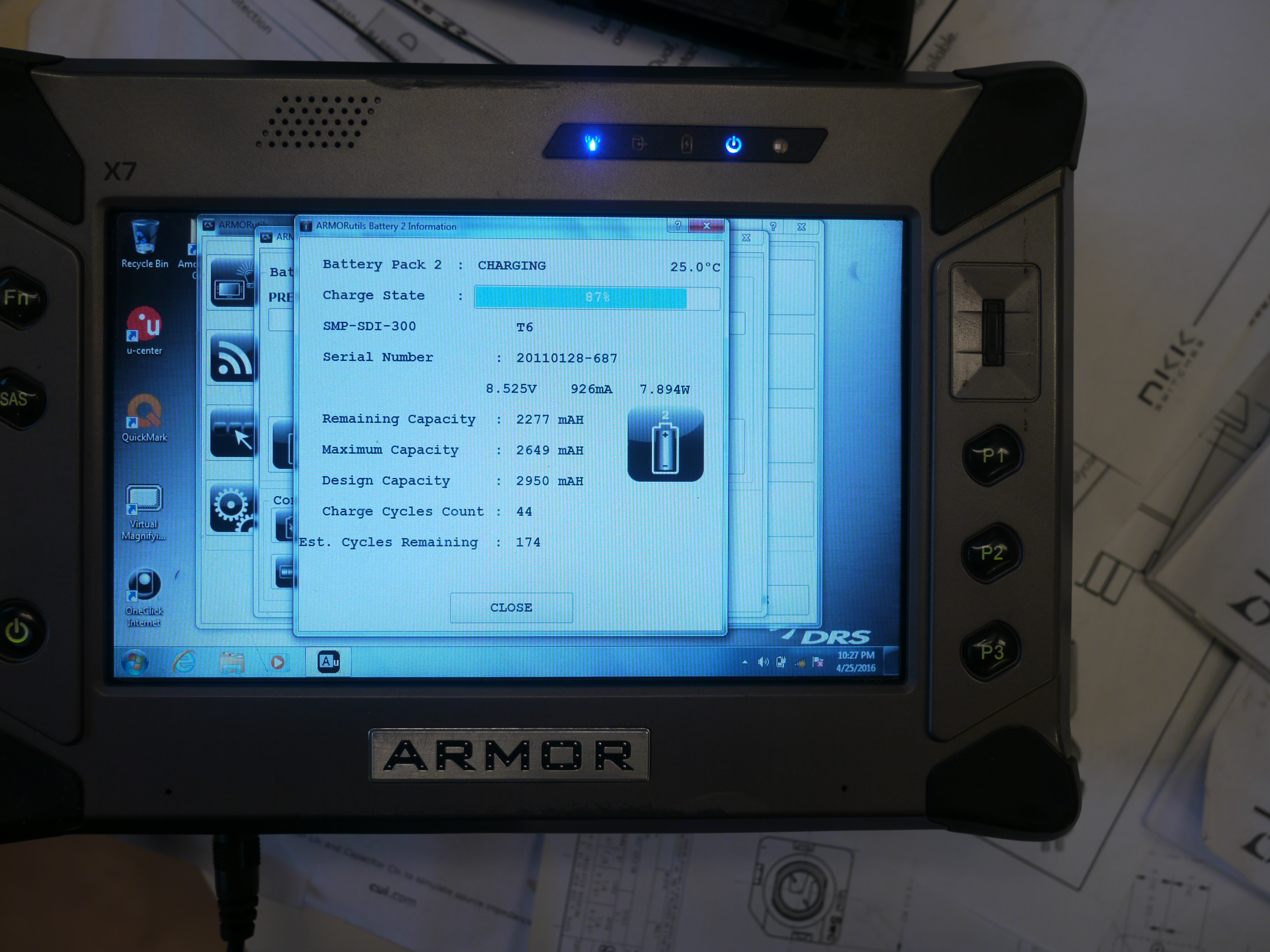
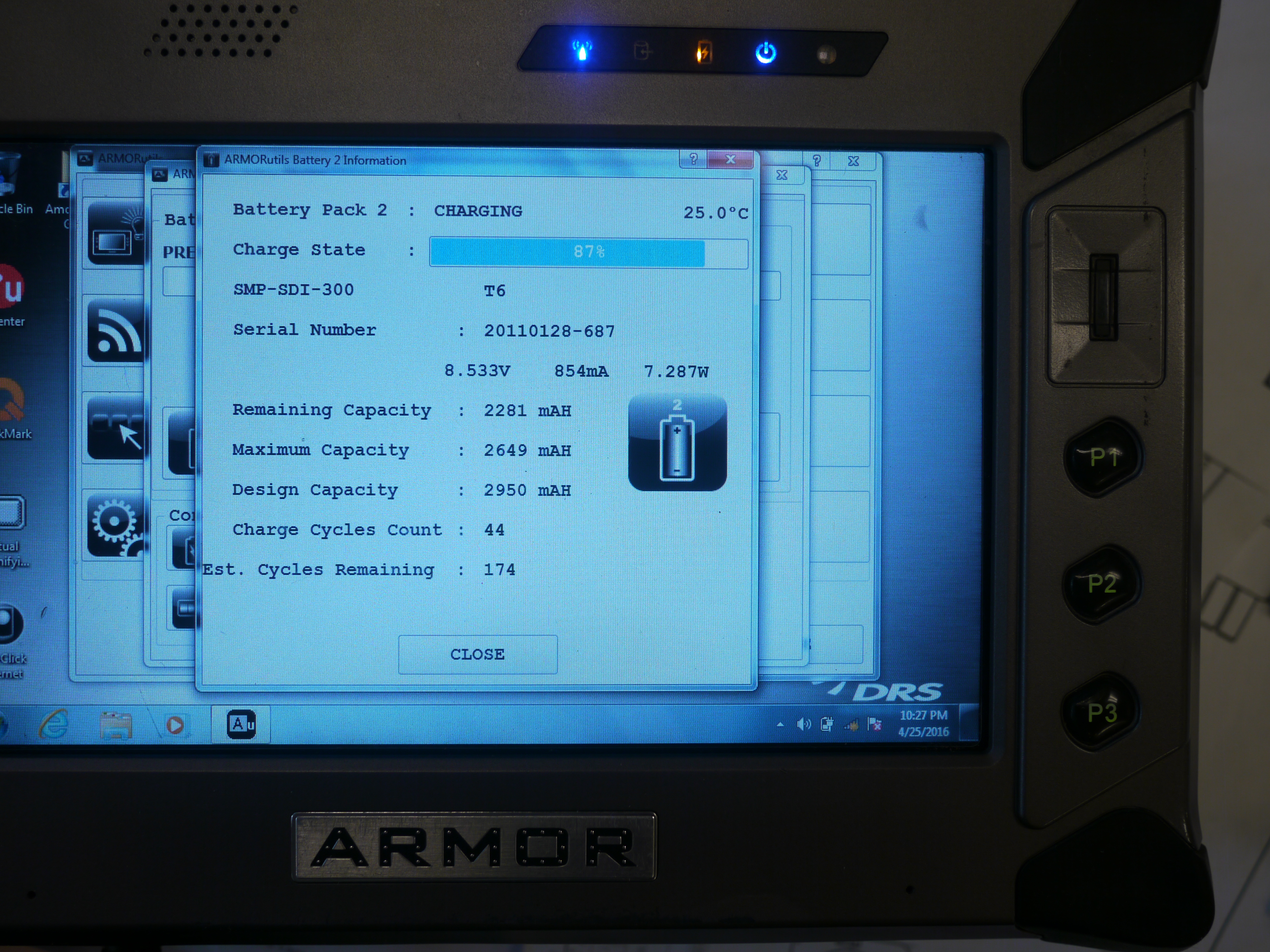
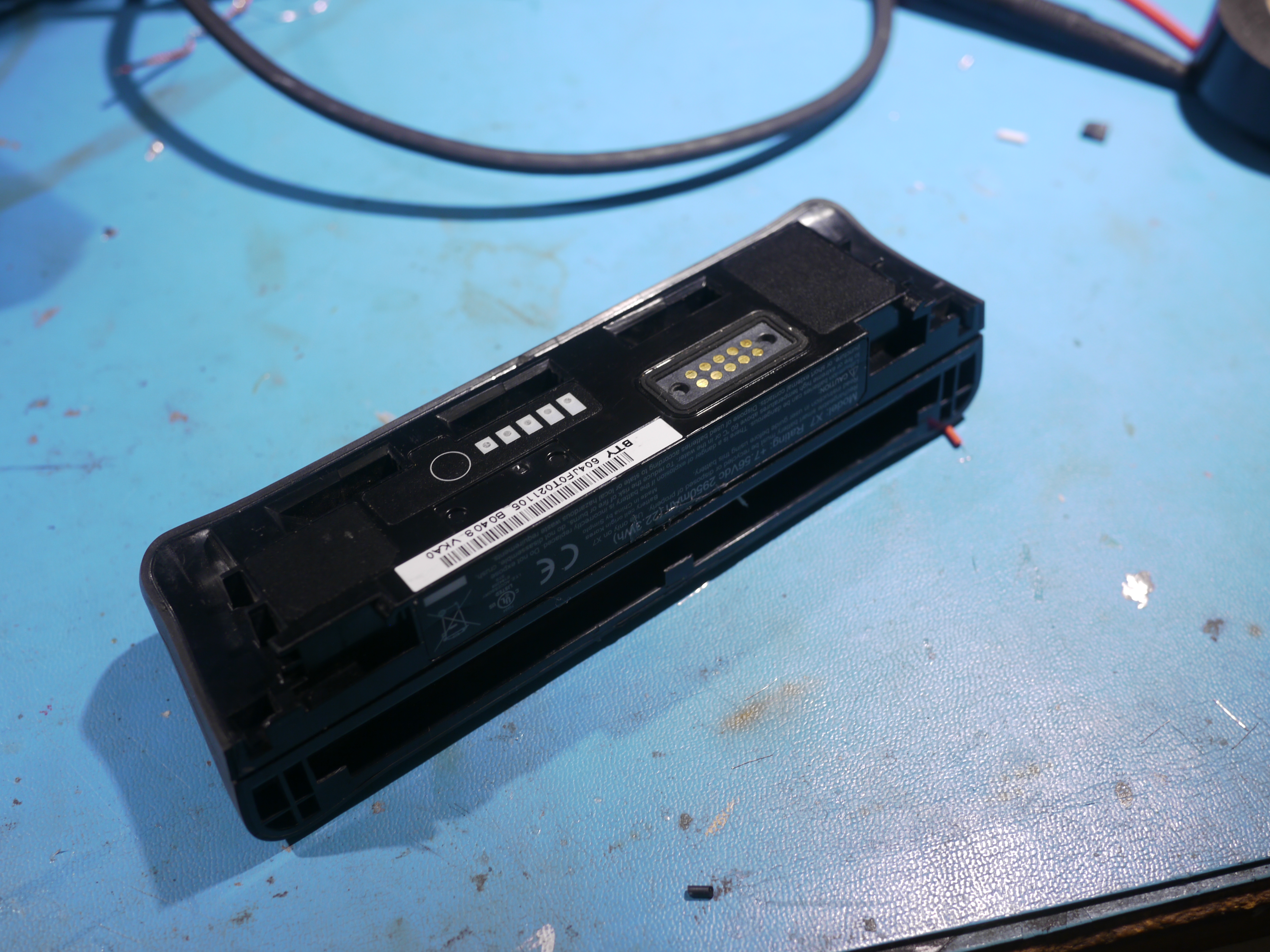
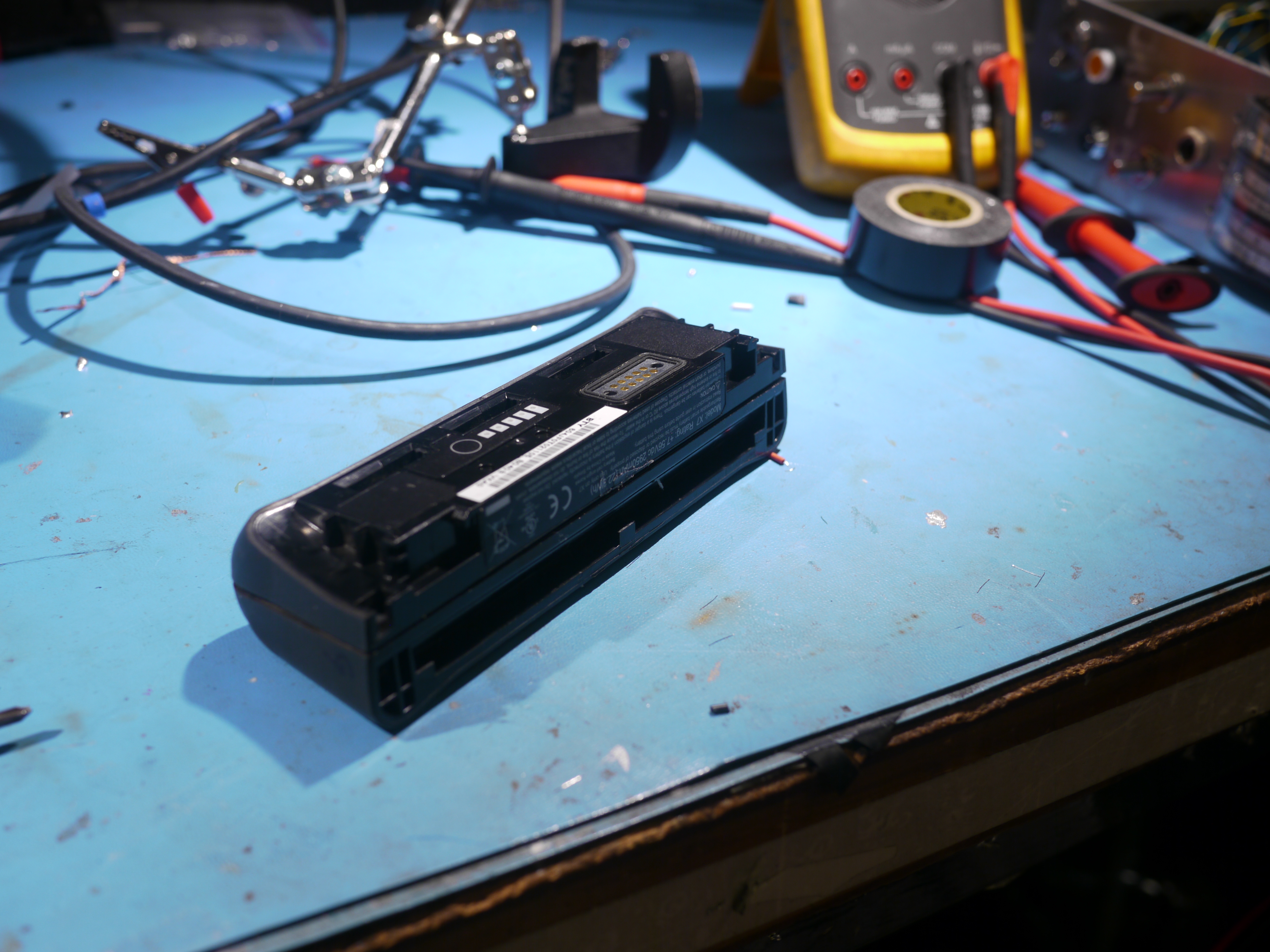
The pack has a small 5-led capacity indicator and a power + coms connector. Upon tearing it open, we find the inside is a 2S1P cell grouping of ICR18650-30A cells. Each 2S1P pack runs the tablet for about 1.5 hrs. Now to find out more about the connector and the cells. 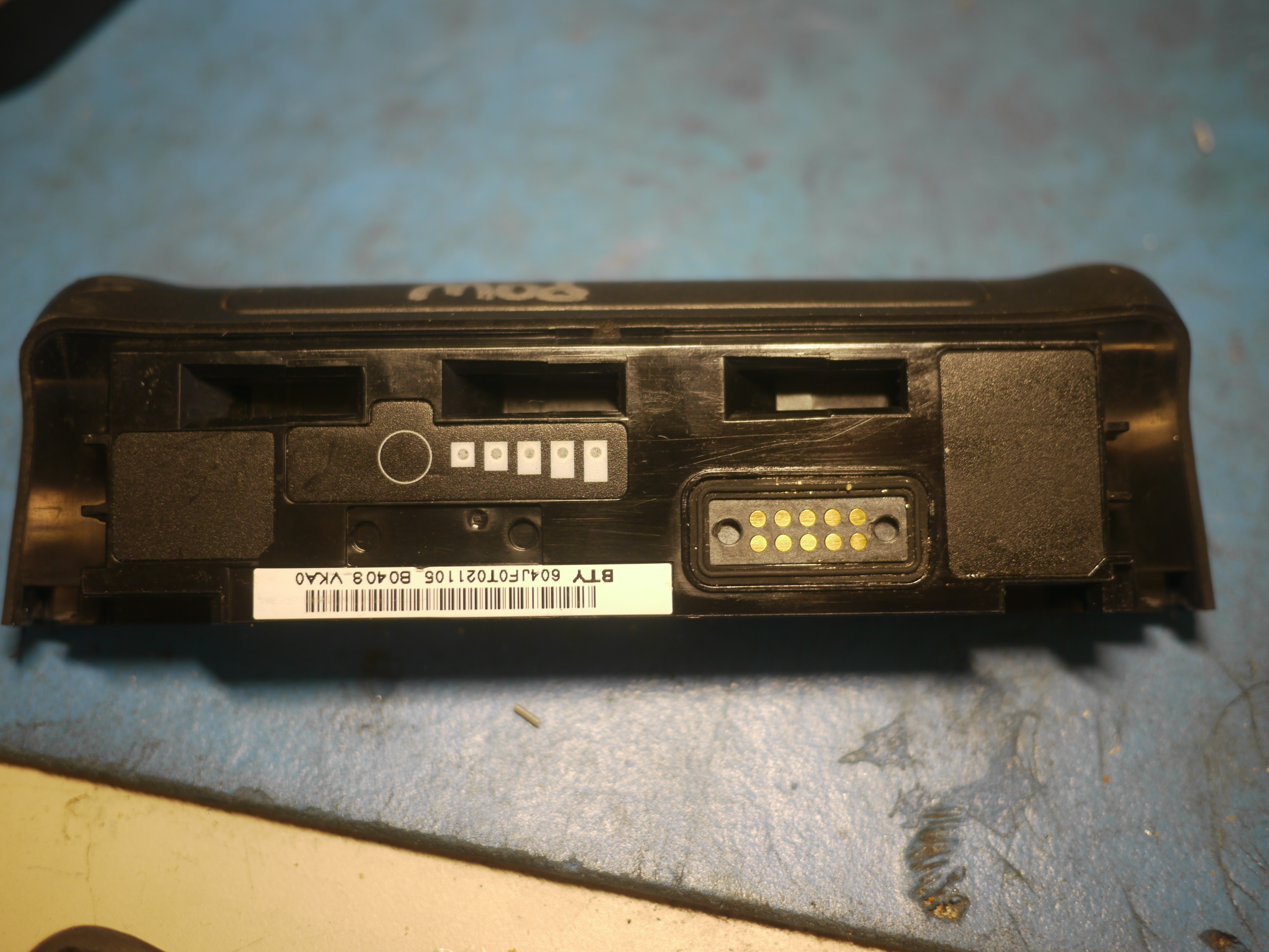
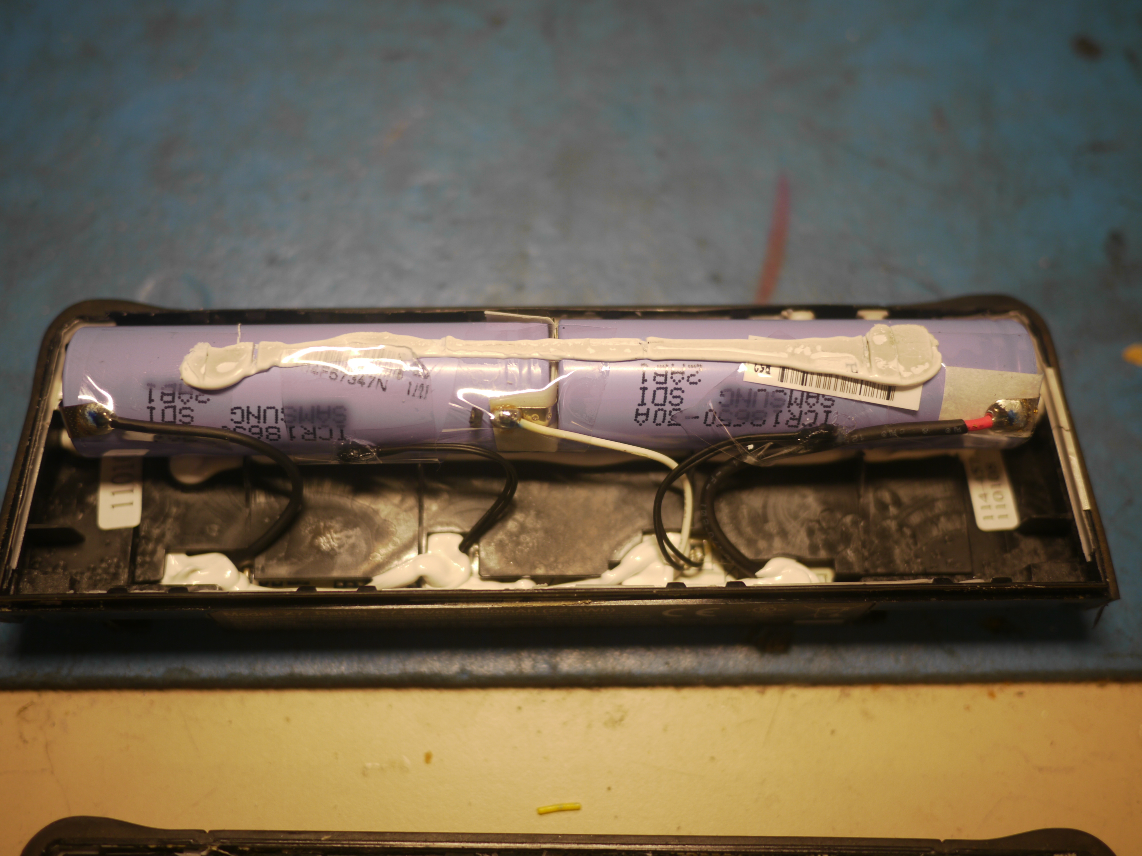
ICR18650-30A cells are a 3Ah 18650 cell with a 2C (6A) max discharge rating. These are nice cells, 3Ah in an 18650 is really high for the vintage of this tablet (early 2010's). 

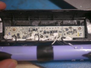
Ok, lets look at the controller. Impressive construction, thermistors adhered to EACH cell, all the voltage sense points strain relieved, and the board itself housed behind a plastic shroud, good deal. Here's where it gets great, the connector is LABELED. THANKS GUYS. That little P+ is Pack P- is pack - and D is SMBC and SMBD. SCIENCE AHOY! 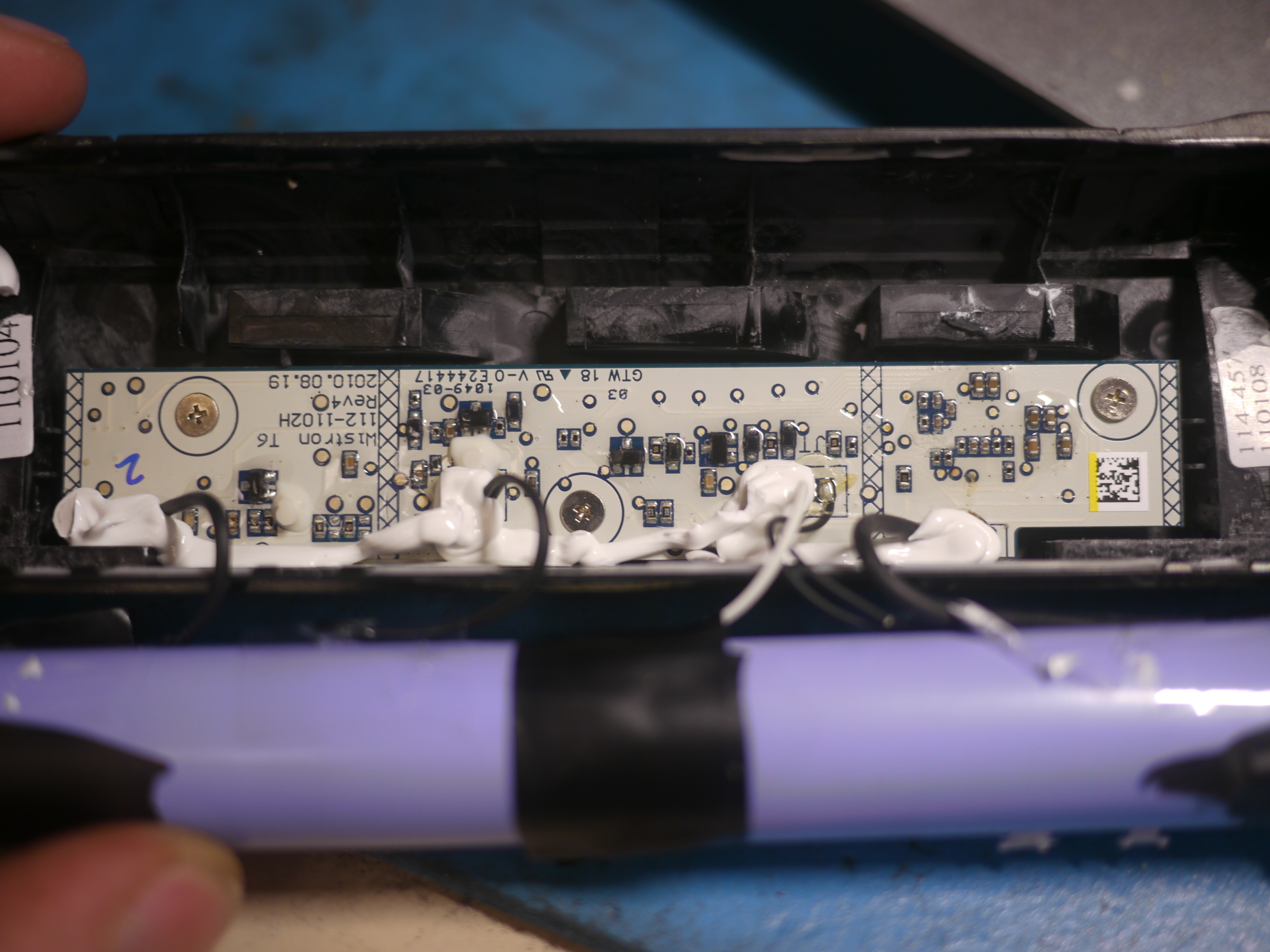
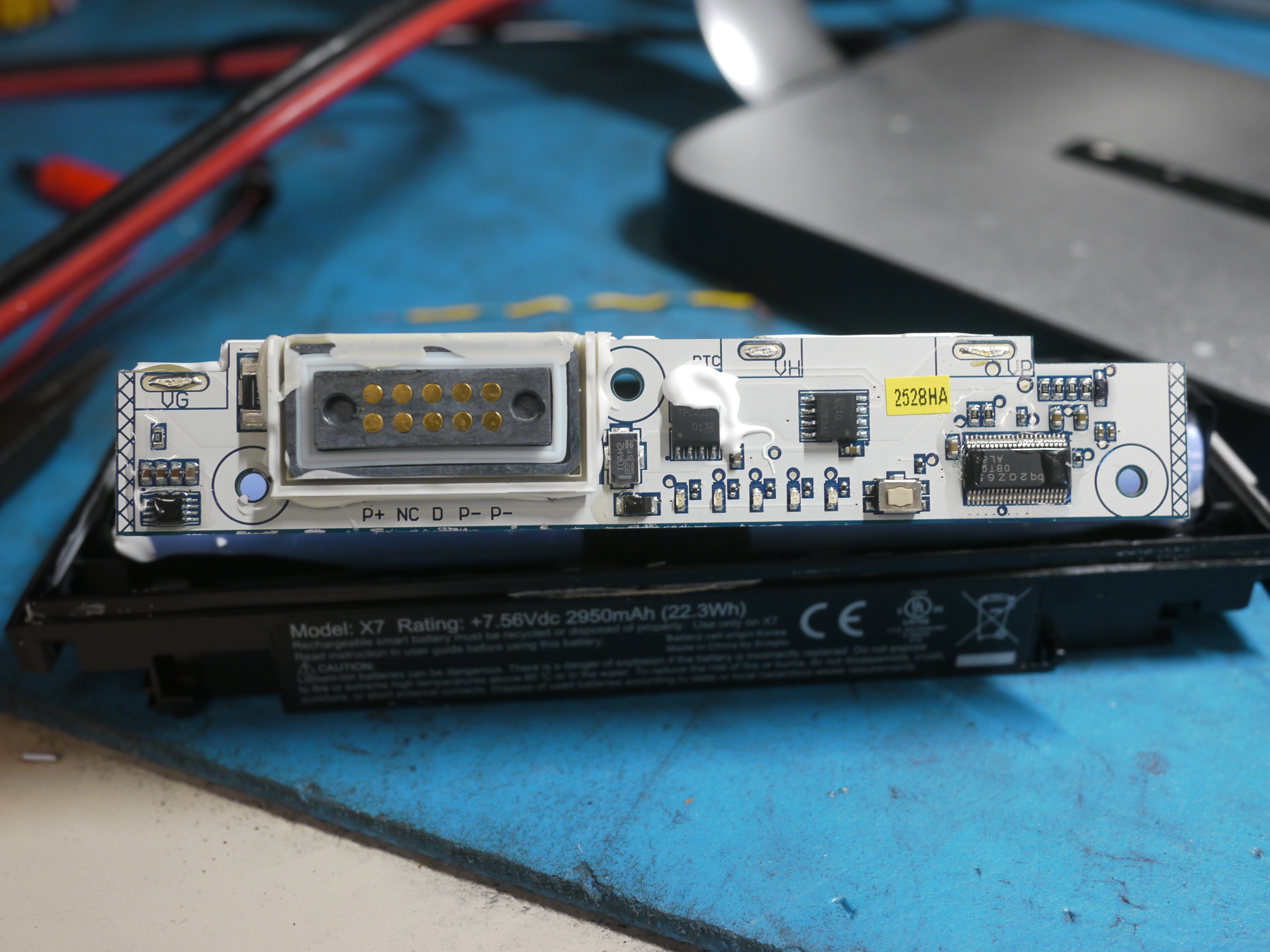
The whole thing comes apart with 3 screws that keep the bms tied to the case. Note the case mechanicals appear to be designed for a higher capacity pack, featuring a 2S2P topology. They probably used a separate BMS board for that pack, as the present board doesnt feature the pads to connect extra thermistors. 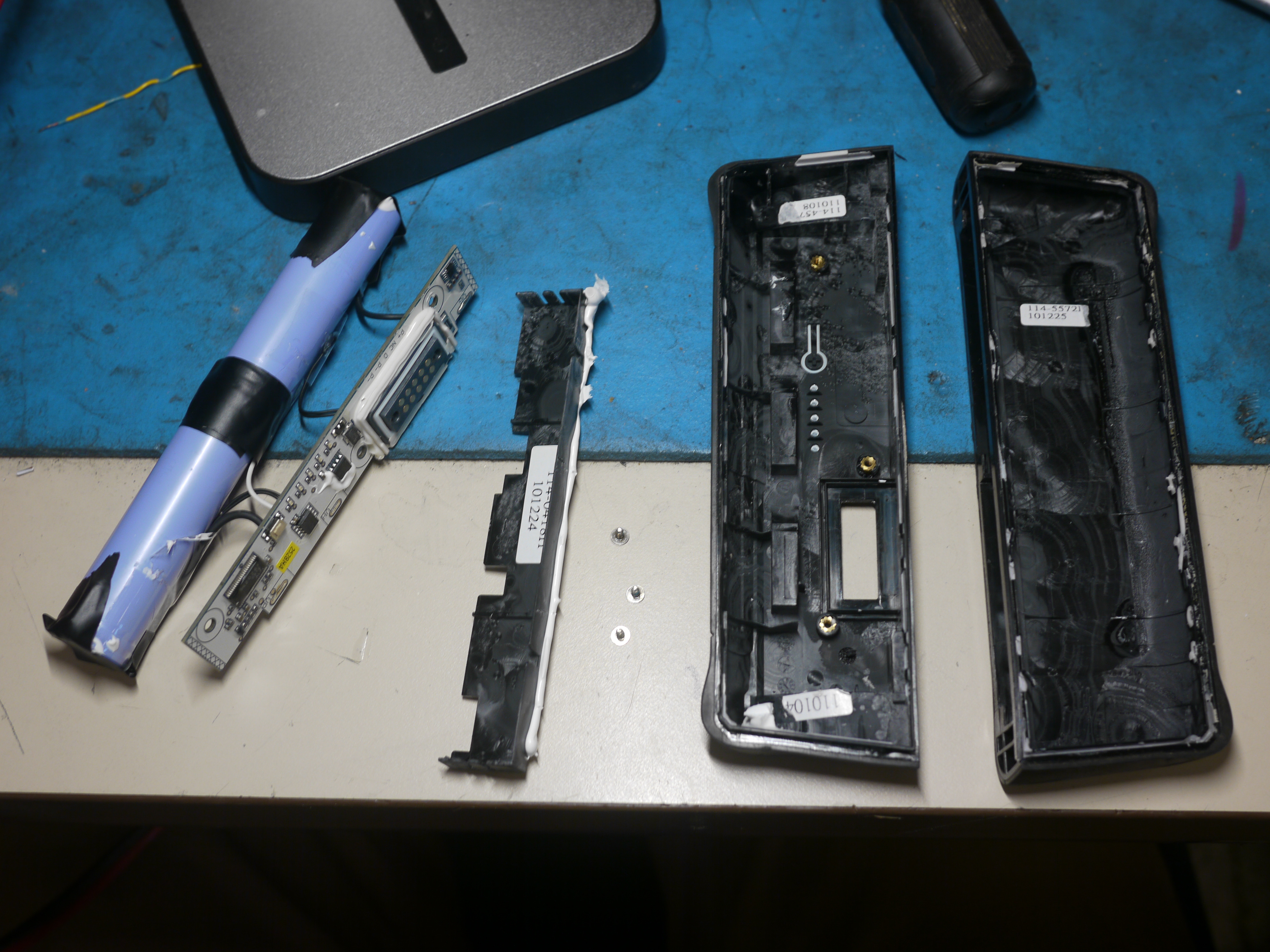
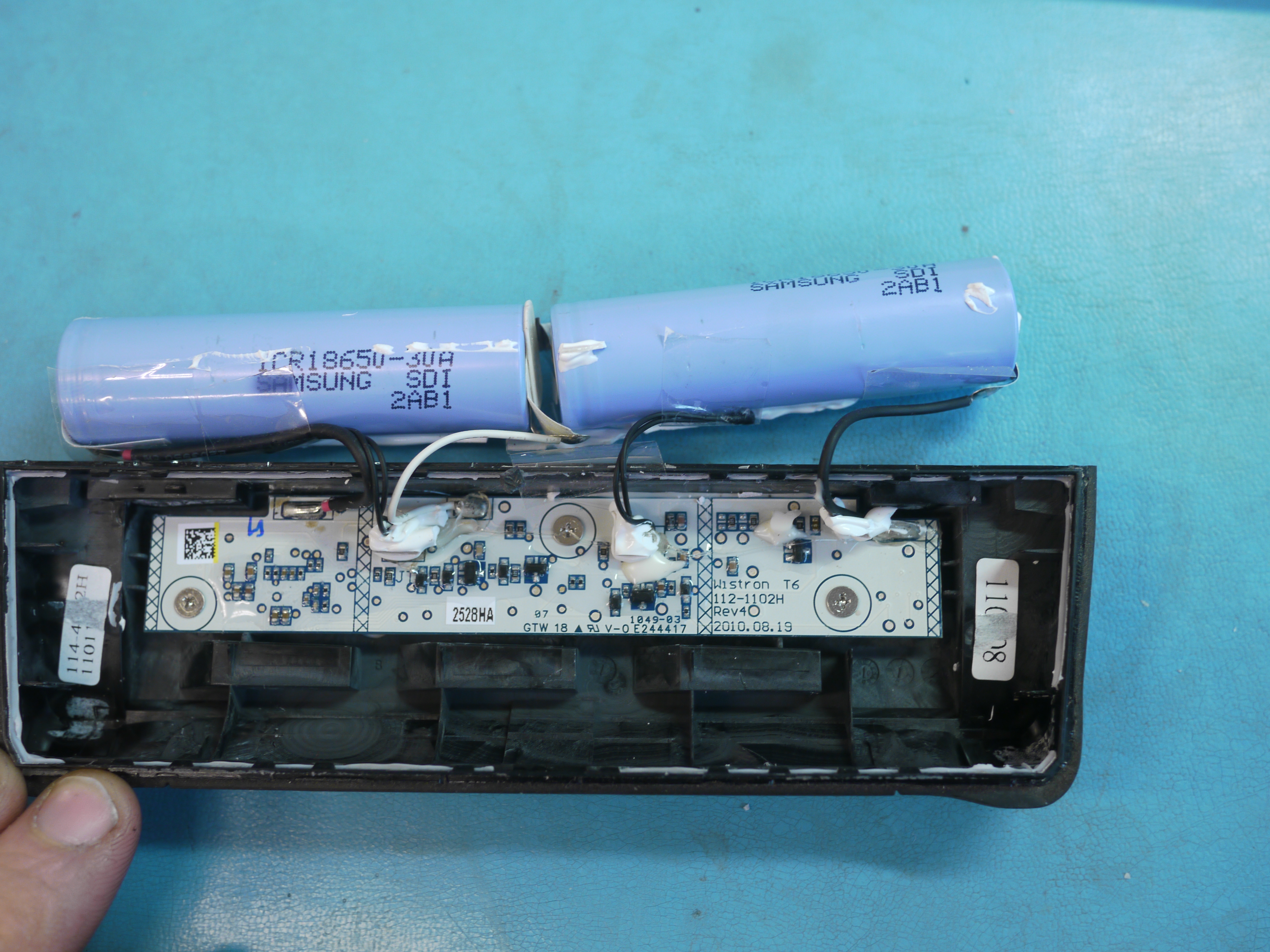
EXTRA ICR18650-30A CELLS APPEAR! To build an 'extended range' pack, i needed extra cells, I grabbed four extra cells from an ebay vendor [link] for 5$ / cell. A quick rudimentary capacity test at a 1A discharge rate clocked in the cells at 2.85ah, which is appropriate. 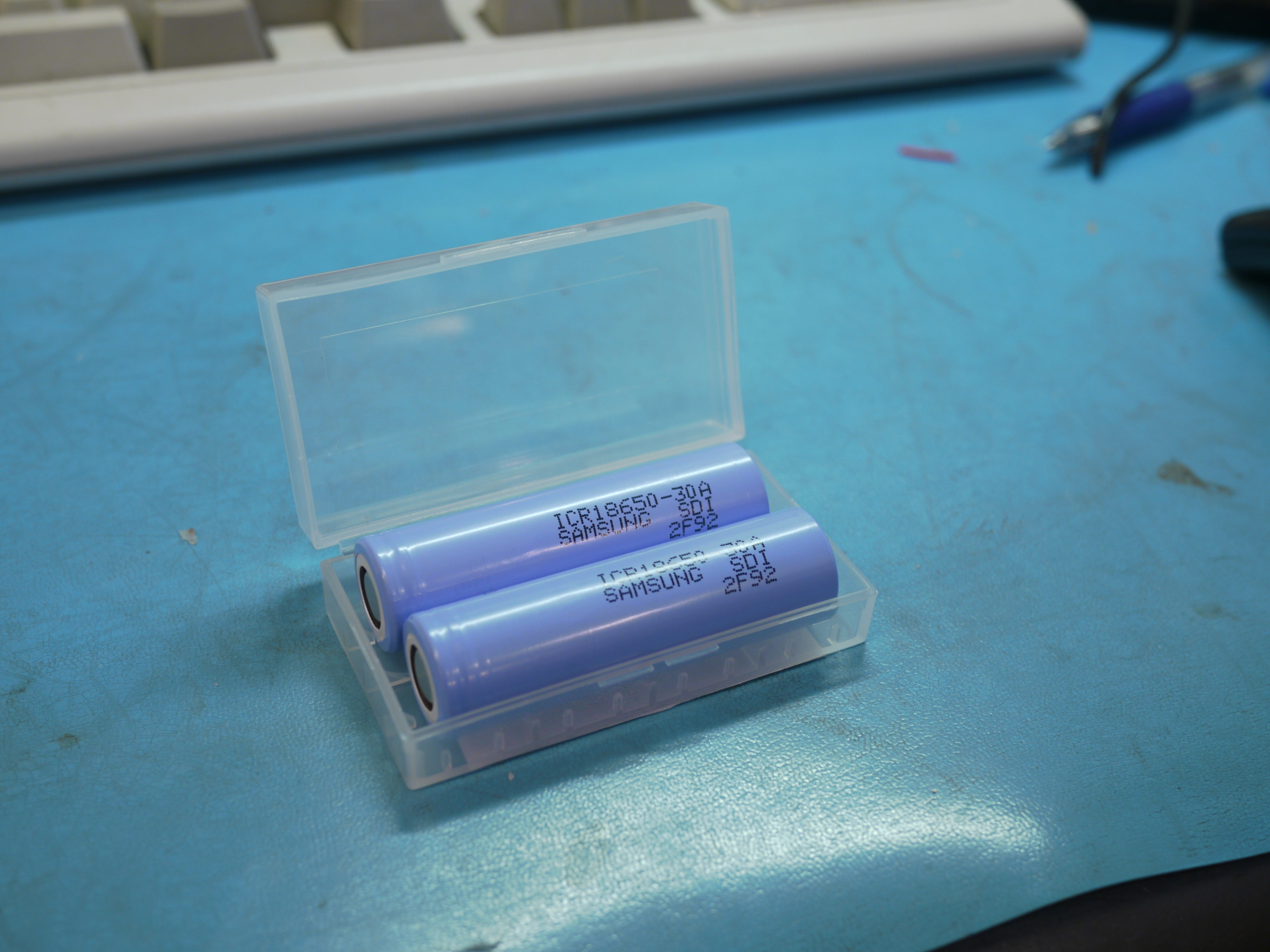
Adding capacity was fairly straightforward, there was reasonable room to fit the extra cells in place along with extra connecting wire. I abraded and tinned the 18650 cells and usd flexible copper mesh to put the extra cells in parallel to the existing cells. Important to note, i spent time to match the cell voltages before parallel'ing the cells. 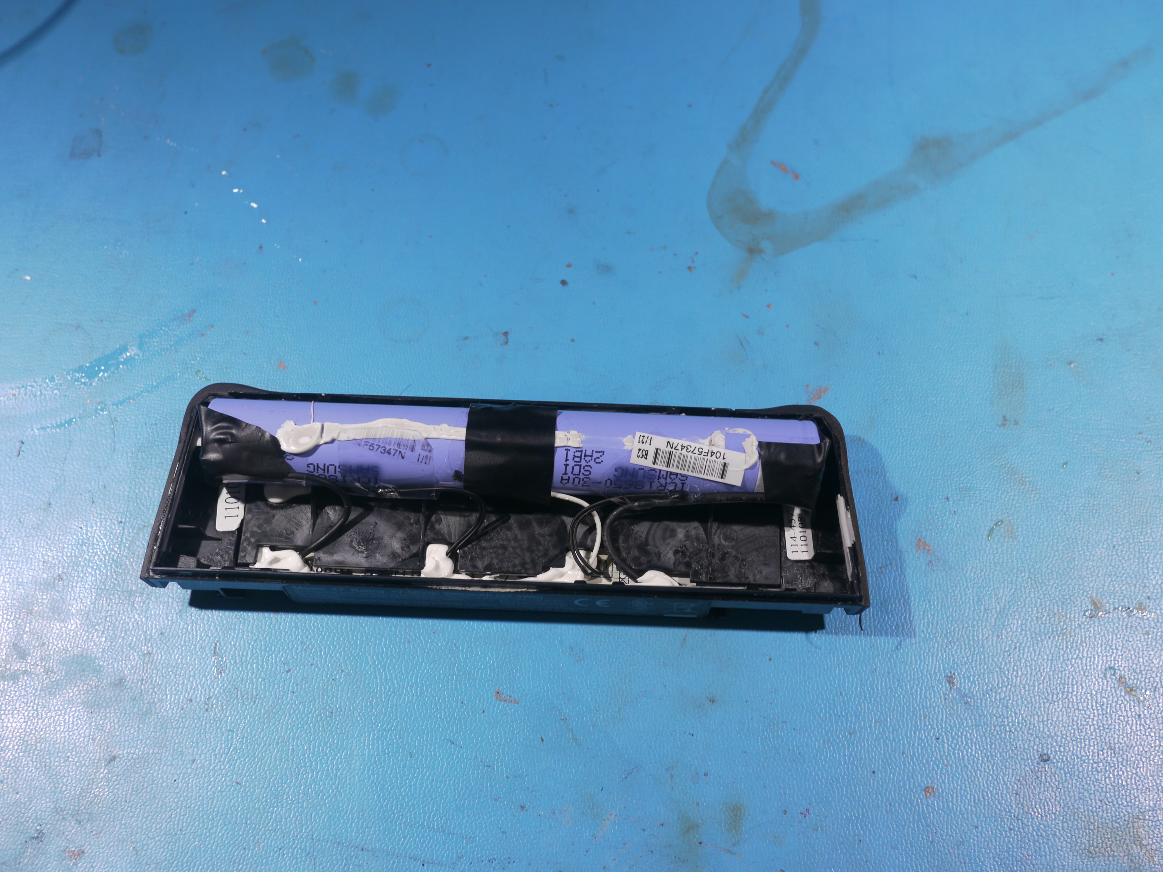
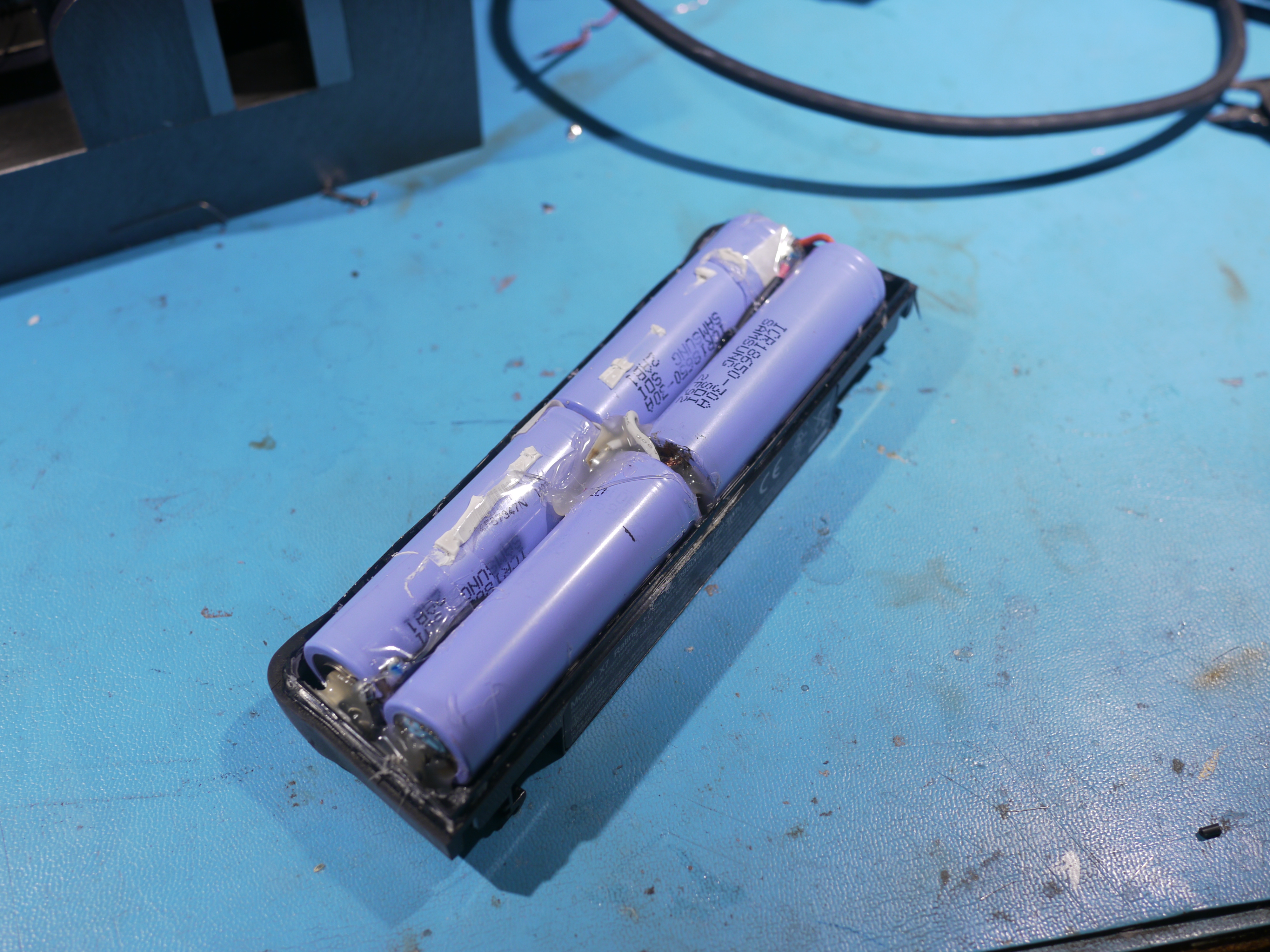
Does it fit? Yep, the 2S2P pack neatly packs away into the same case, I added a label to keep track of it. Now to find out if the BMS magically accepts its DOUBLED capacity. 
NOPE, BMS gets a bit confused. This plot is gathered from BatteryInfoView, an excellent windows battery data collector. Orange is pack voltage, blue is the BMS's precieved capacity (mAh). Unfortunately after a few cycles it didnt creep up. The battery is using its initial 'manufacturer' battery capacity and estimating capacity from that number. This results in the tablet shutting off very early and reporting innacurate time remaining. 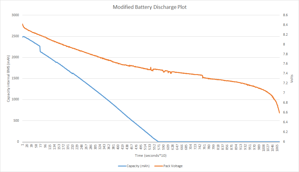
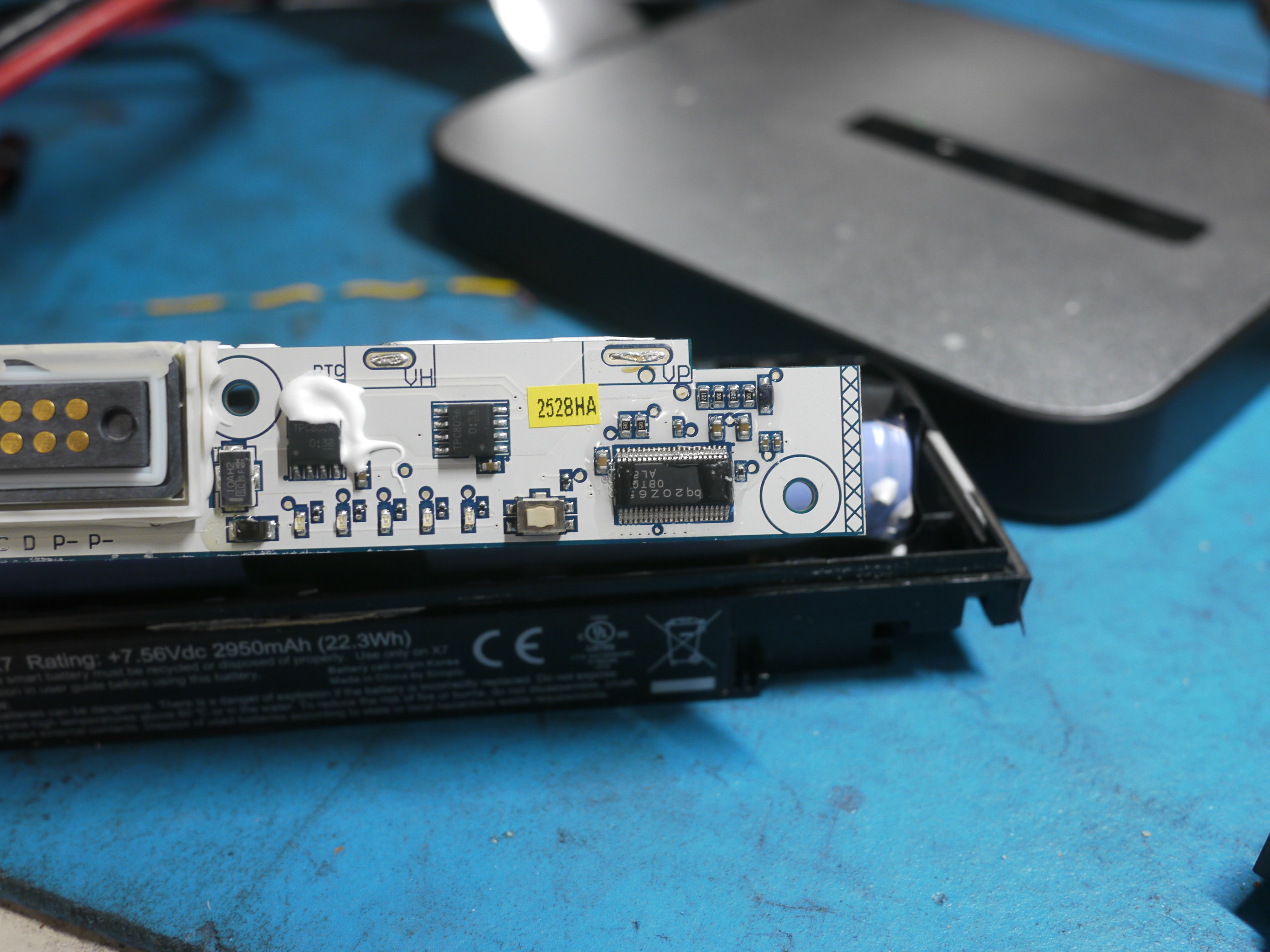
The bms reports to the OS the %SOC or state of charge, windows/linux takes an action at %SOC thresholds, like putting the system to sleep, etc. In this case, the system ran to 0% SOC and, kept running for another hour and a half before getting a hardware undervoltage cutoff from the battery pack. Its nice to have a reliable % SOC, especially if you're running about in the battlebox or outside collecting data. To get this, we're going to have to dive a bit deeper and let the BMS micro know whats up, ideally changing the full charged capacity to 5800 mAh instead of the existing 2900 mAh. The micro/bms is visible above, and is a BQ20Z65. Talking to a TI BMS Chip
Tell me more about this BQ20Z65. Theres a few documents that come in handy when getting a feel for this part. 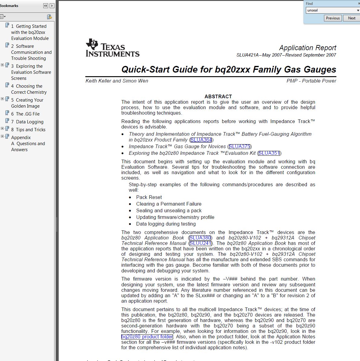

General Design. The datasheet publishes a basic application schematic, which is really similar to our battery pack. Note there's one external IC to the main BMS, its a secondary OVP chip. This kicks the fets off if the main BMS kicks the bucket. Note there is no external EEPROM, all the settings are stored inside the BQ20Z65 part. Had there been an external EEPROM these settings may have been modified easier. 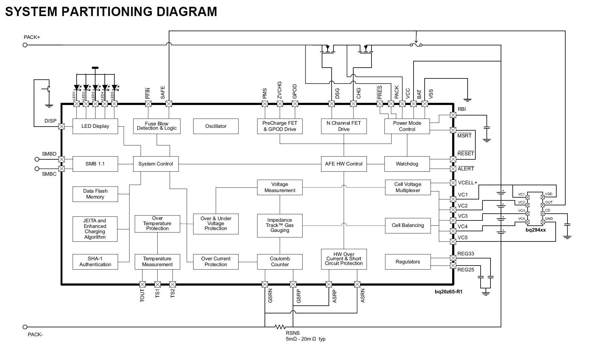
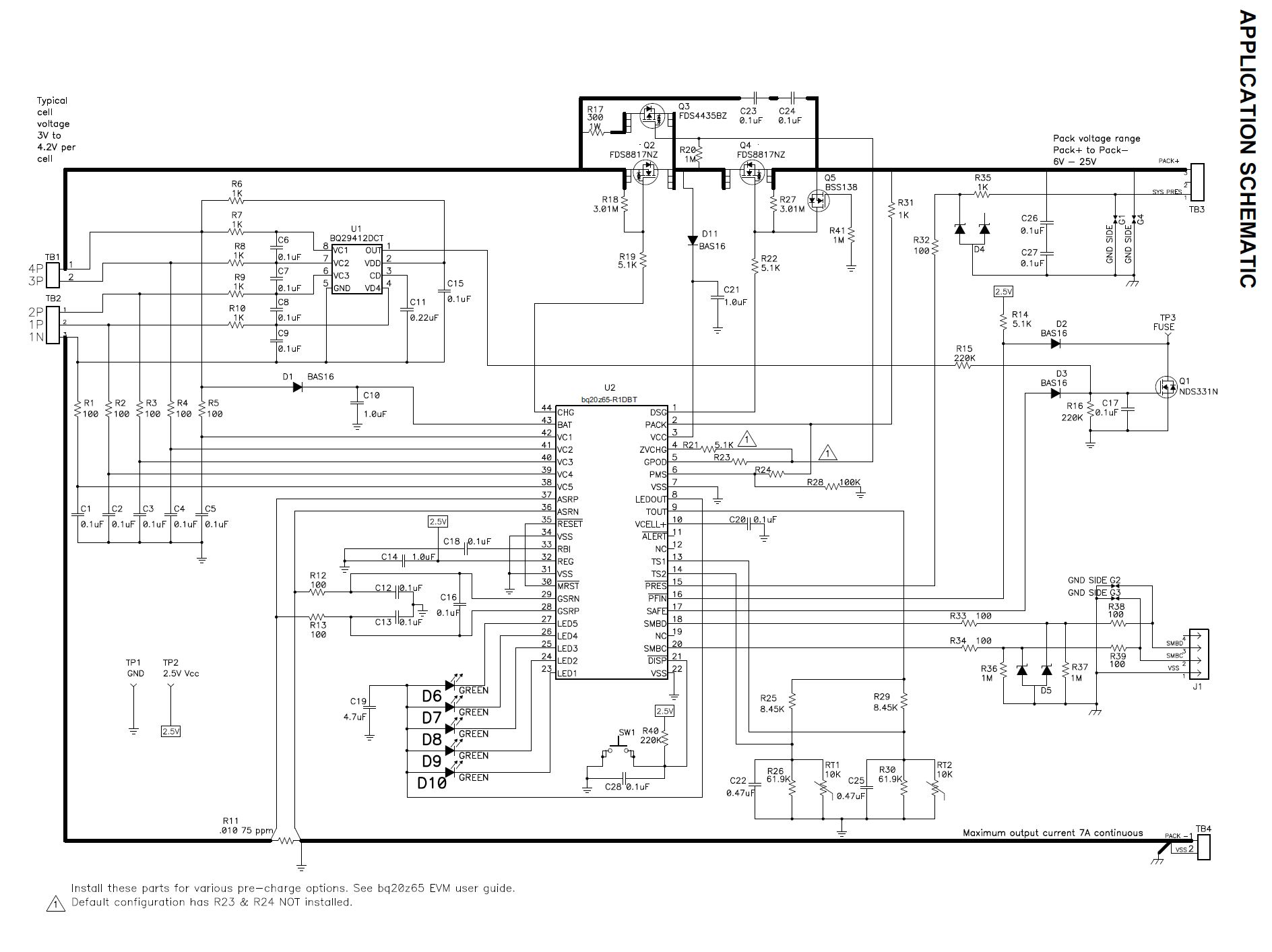
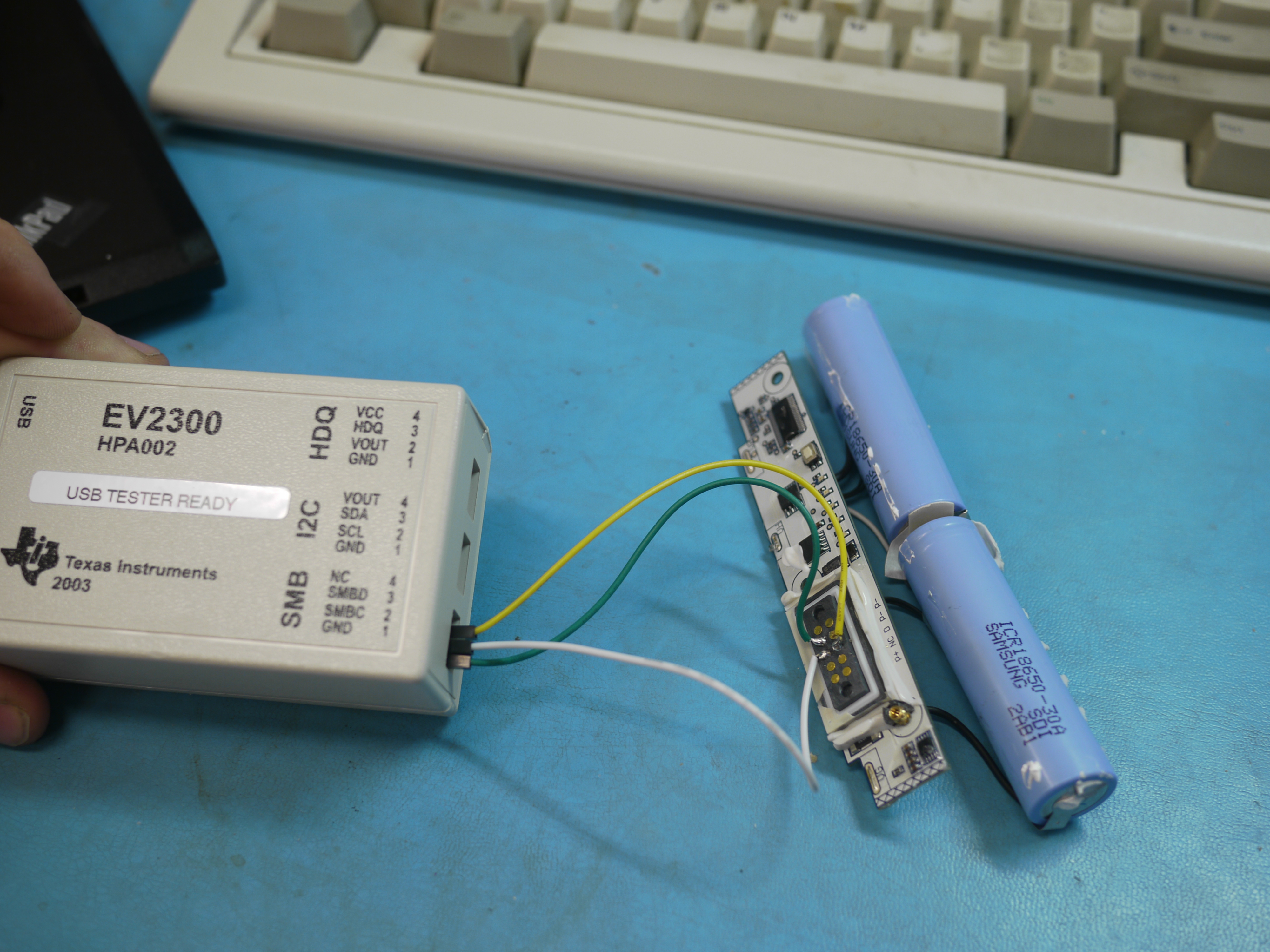
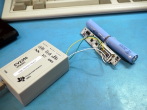
So we learn that the coms are SMBC and SMBD, time for the EV2300 and some old BQEASY software. Connect SBMC,SMBD and GND to the pins shown. Note the EV2300 is available here, and only really works on WINXP, Plan for headaches if you want to run on WIN7 64 bit. The EV2300 is also available on ebay. 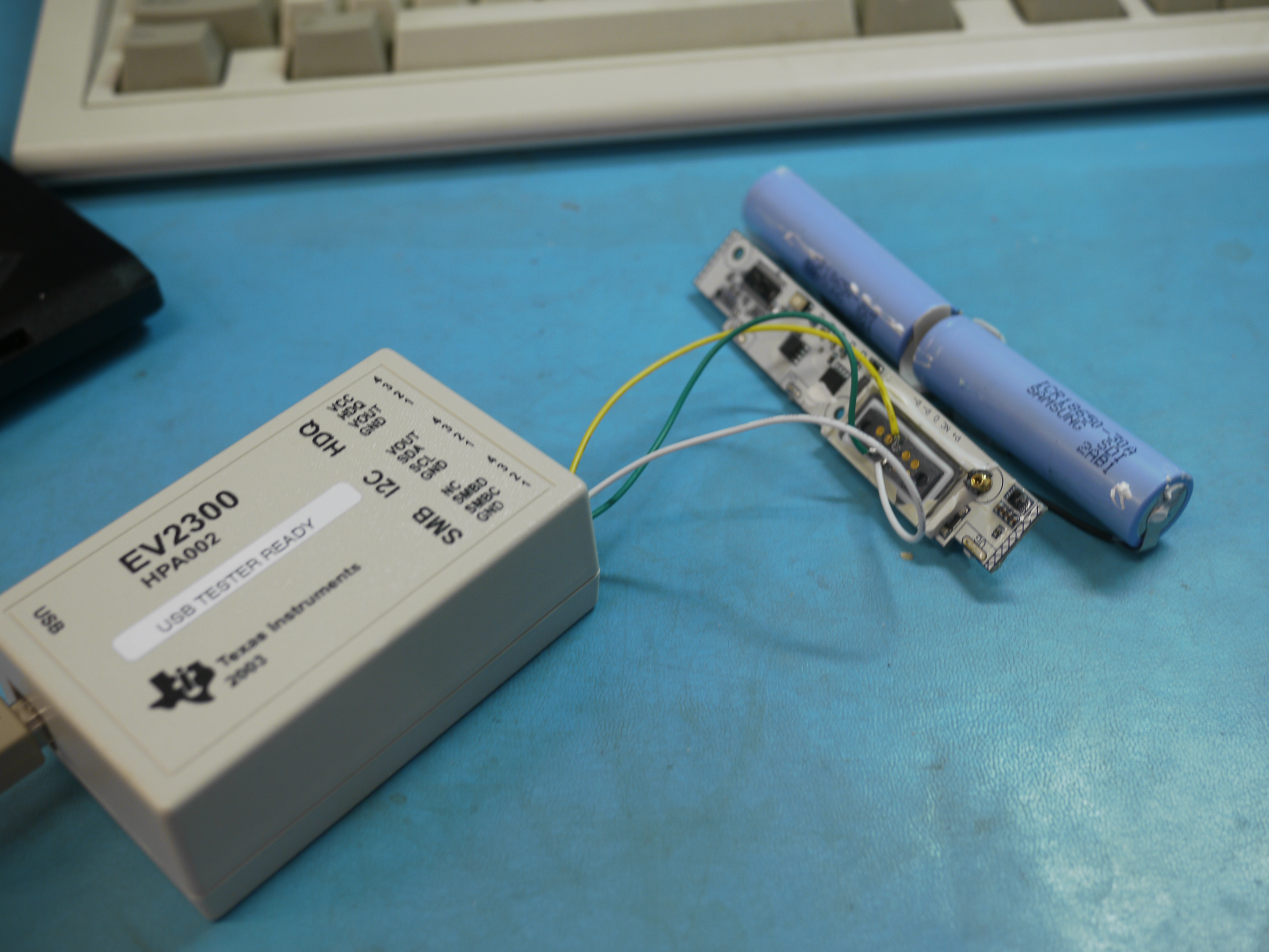
Whats BQEASY?, it sounds like a BBQ Sauce... BQEASY is the user interface to the SMBUS communications to the host battery, here's the intro-guide [Link] [Local Link]. You want to pay attention to a few Flags, namely SS and FAS. If SS is red, the unit is 'sealed', if FAS is red, full access is restricted. In the case shown, the unit is in 'sealed' mode, and only a few things are available to read. 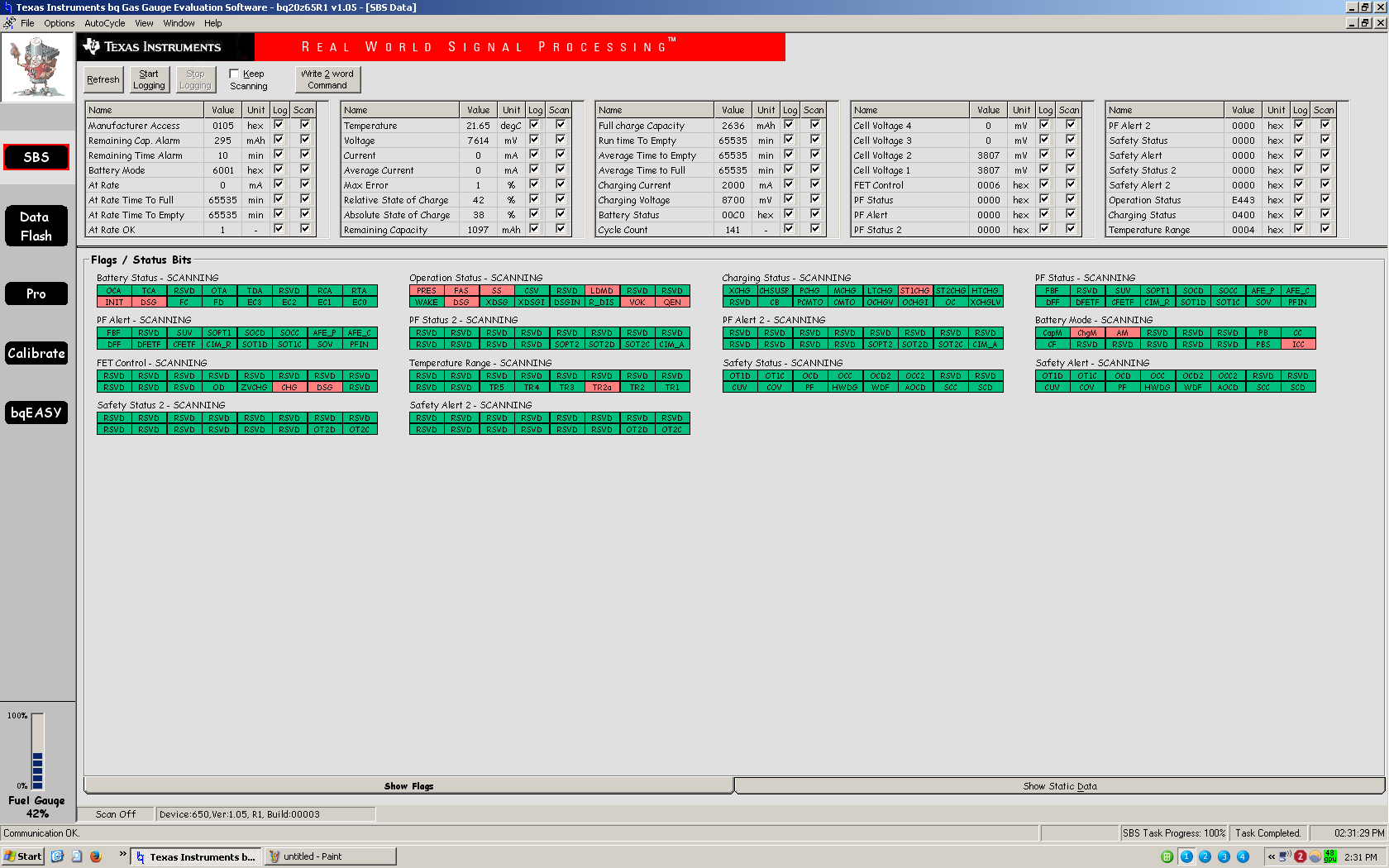
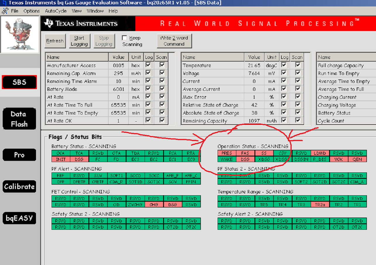
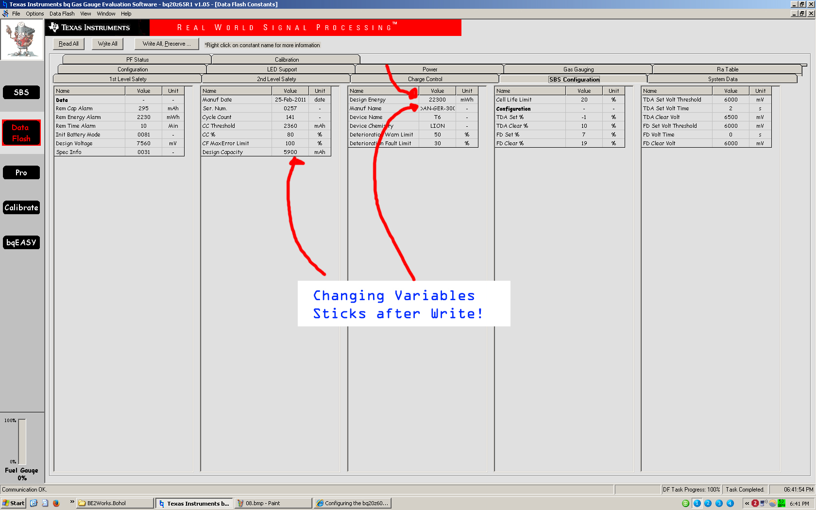
There was some futzing around here, as I had never used this software. There's a lot of jargon, and hunting through forums so here's a better overview. The SBS window gives you a quick overview of all the system 'flags' as well as pertinant variables. Flags are green/red and indicate states [is the discharge fet on, is the unit 'sealed, etc]. Data Flash is only available in unsealed / Full access mode. In this mode you can change everything from thresholds to led meter pulse states. Pro allows you to read and write strings or words and get / insert useful data. Again, only functional in unsealed / full acccess mode. The whole shebang functions as a datalogger, which is great for tracking accuracy of the system. Manufacturer access is a magic area where 4 digit word commands can be submitted. 2 word commands can be inserted right above manufacturer access. 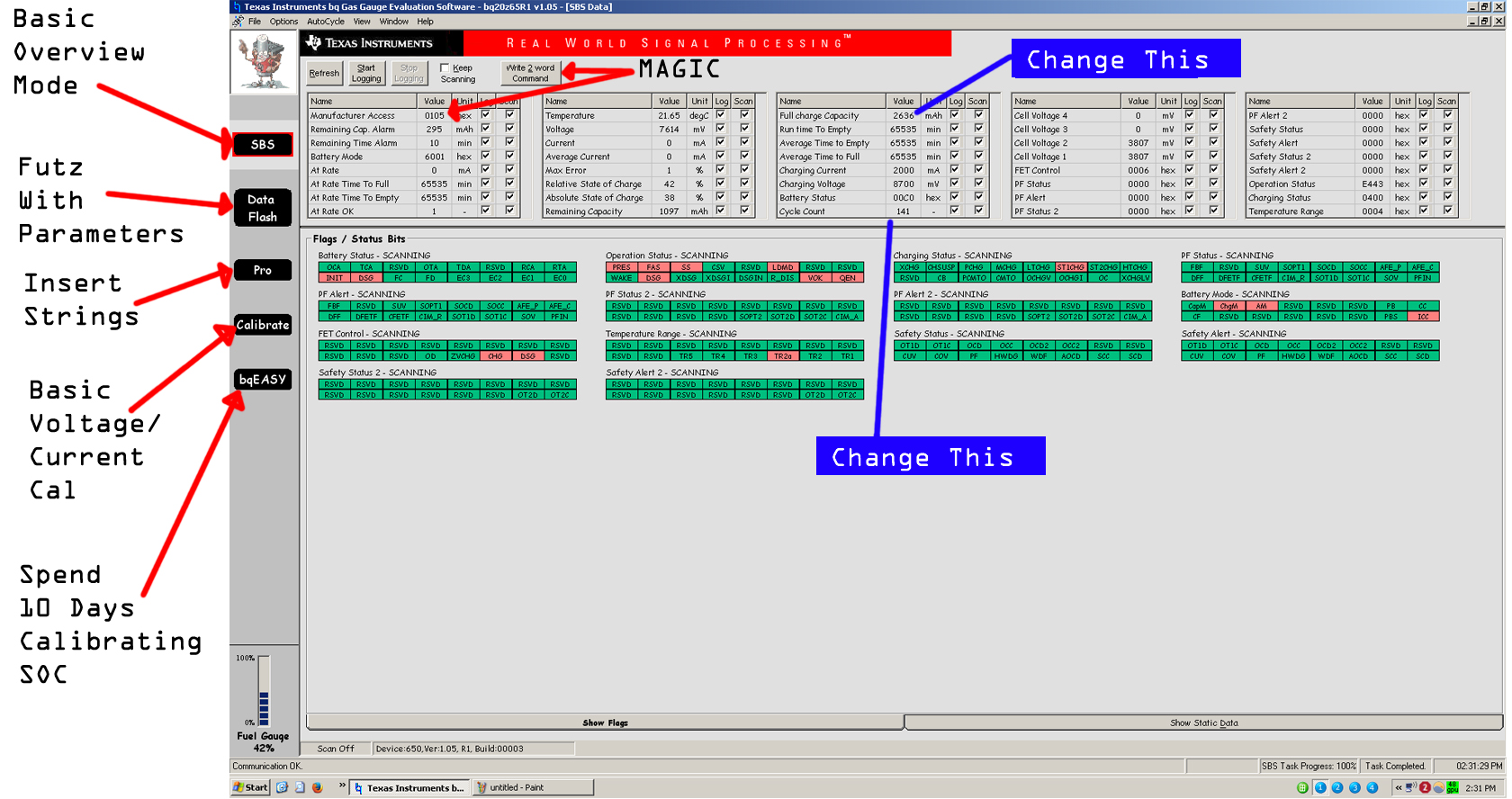
Ok So lets get out of sealed mode. You will note that if you go to Data Flash and hit read, you get an error. As i mentioned before, this unit's BMS is sealed. Data Flash is basically inaccessable. For this excersize, i'd like to change the 'Full Charge Capacity' variable to ~5800mAh instead of 2636mAh. Changing the manufacturer name would also be interesting. 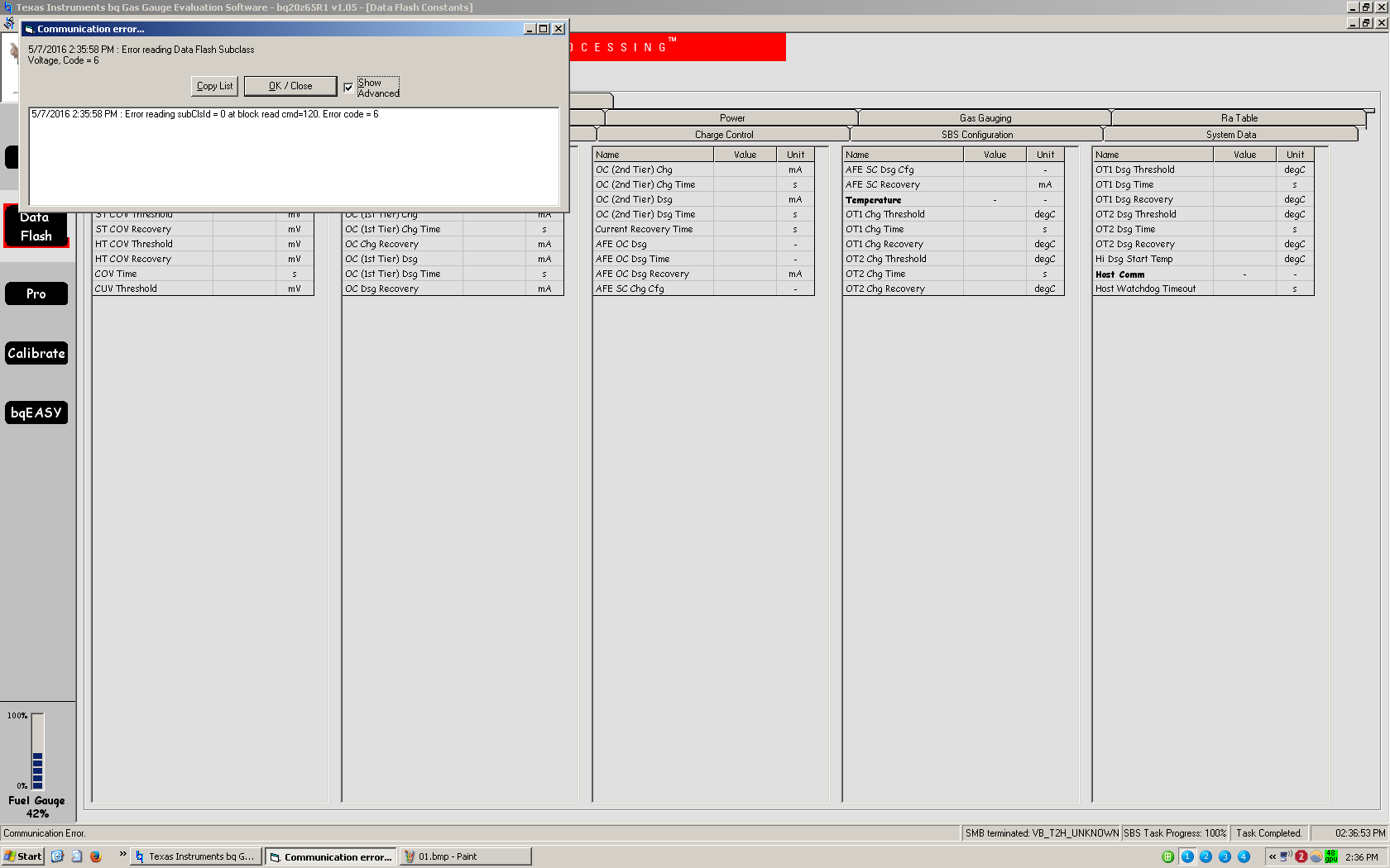
So lets begin, To do this the pack needs to be fully discharged 'Fuel gague = 0%' and some magic needs to be inserted. To fully discharge your pack, i placed a load resistor (10 ohms 10W) across the pack +, Pack - terminal and watched the Fuel Gague deplete to 0%. 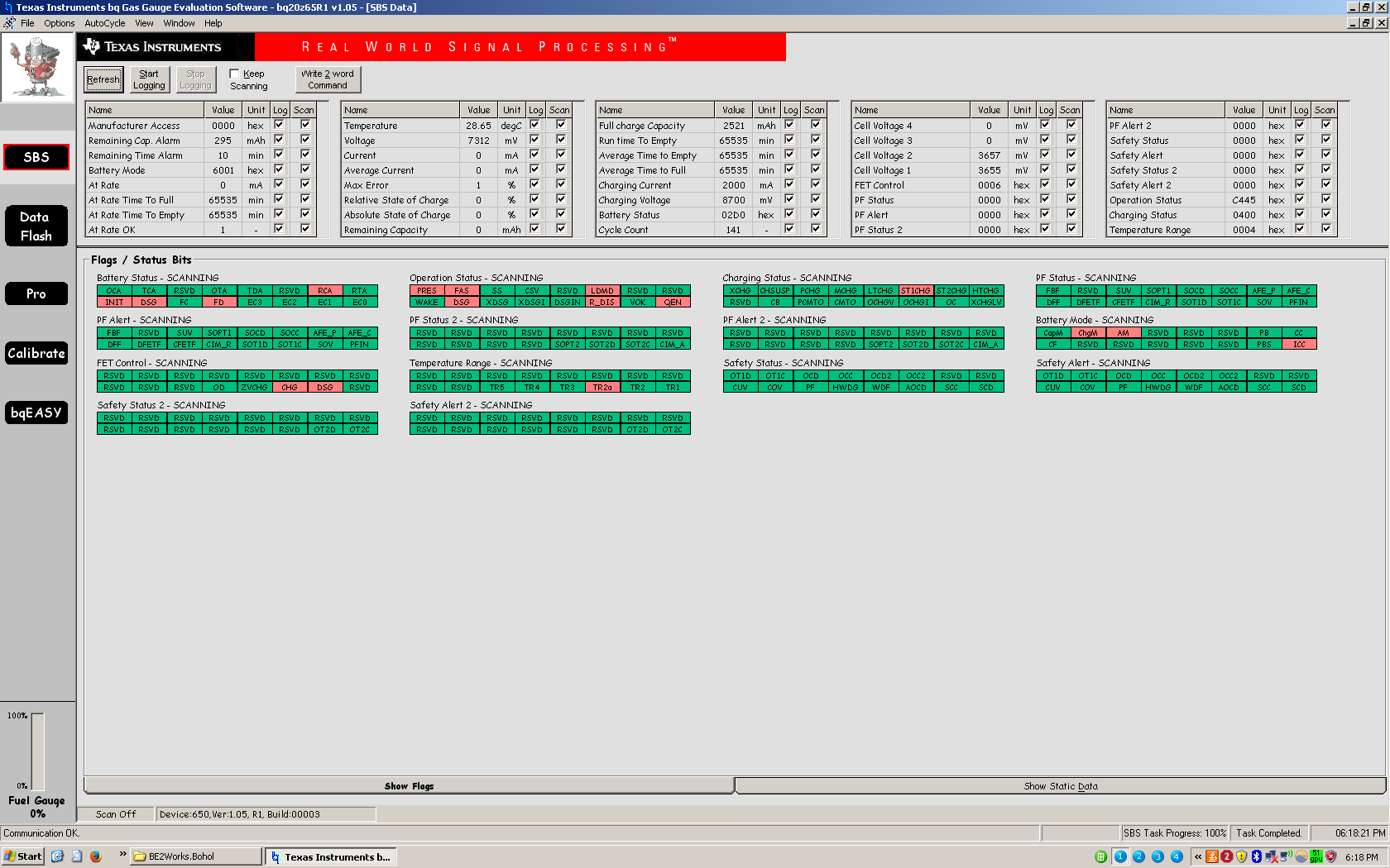
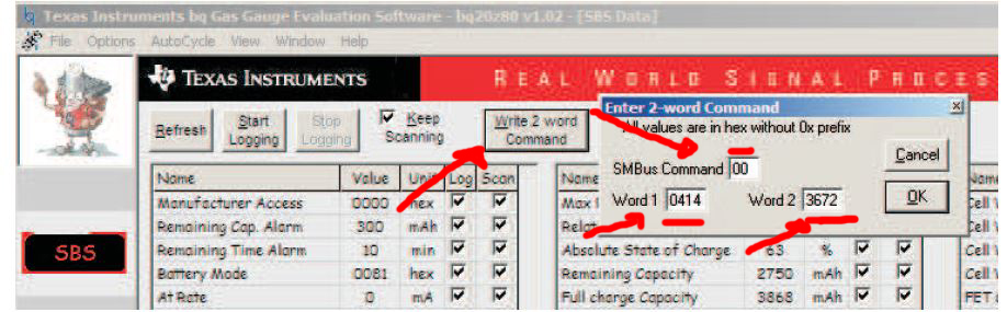
Ok, Full access time. Hit 'Write 2 Word Command' again, enter 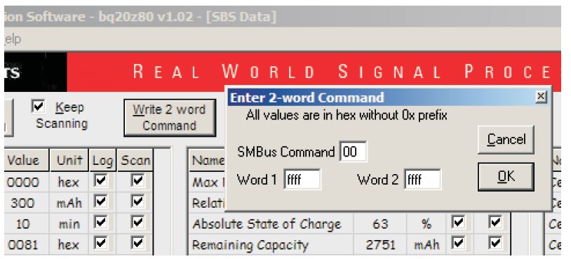
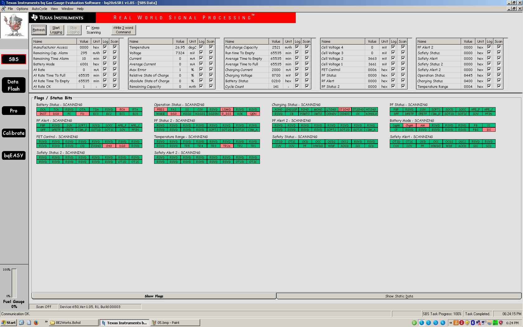
And lo, Data Flash is now editable, I changed the vendor to DAN-GER-300 (11 characters max) and i changed the design capacity. After editing a variable, hit enter, right click, and select 'write'. Use refresh all to verify the written variable 'stuck'.
Checking that it worked. I removed the solder points connected to the battery and cleaned them with solderwick so they appeared planar with the non-soldered pins. Next up the battery pack was plugged back into an Armor X7 tablet and the following was grabbed with BatteryInfoView. Note DAN-GER-300 is visible along with the increased Design Capacity! 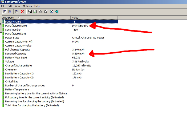
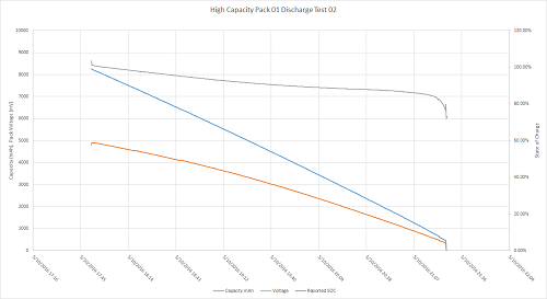
Putting it back togetherHigh Capacity Module 1, two cyclesUsing the newly born high capacity pack, i cycled the battery twice. This consisted of fully charging the pack by leaving the tablet plugged in for a few hours, and then begining logging using BatteryInfoView. The tablet was configured to leave the screen on and run till dead. The hiccup on both plots was caused by the %SOC reading zero, the tablet going to sleep, and then me subsequently waking it up to allow the remainder to drain out. In these cycles the pack came in at 4.6 and then 4.9 Ampere-hours. The run time also was excellent, 3hrs and 35 minutes on one 'double-pack'. Cycle one: First cycle with new cell parameters 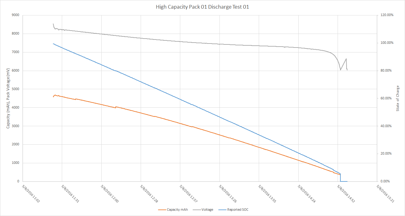
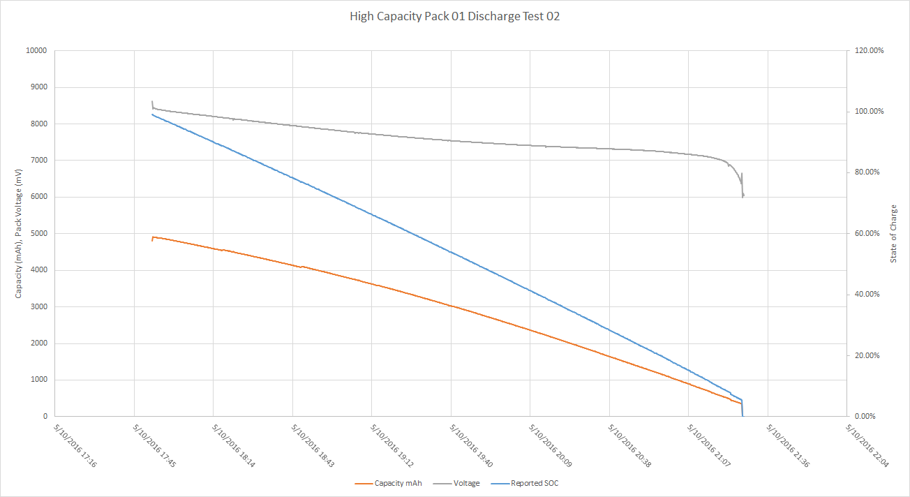
Take a look at the comparison of the before and after plots. State of charge no longer ends halfway down the SOC plot, it is fairly accurate at predicting state of charge. There's a long way to go to making it super-accurate, and that will be covered in another writeup.
Before Firmware modifications
Opening up the Armor X7The armor x7 has some interesting insides, the following contains a teardown of the unit. Specs from [link]
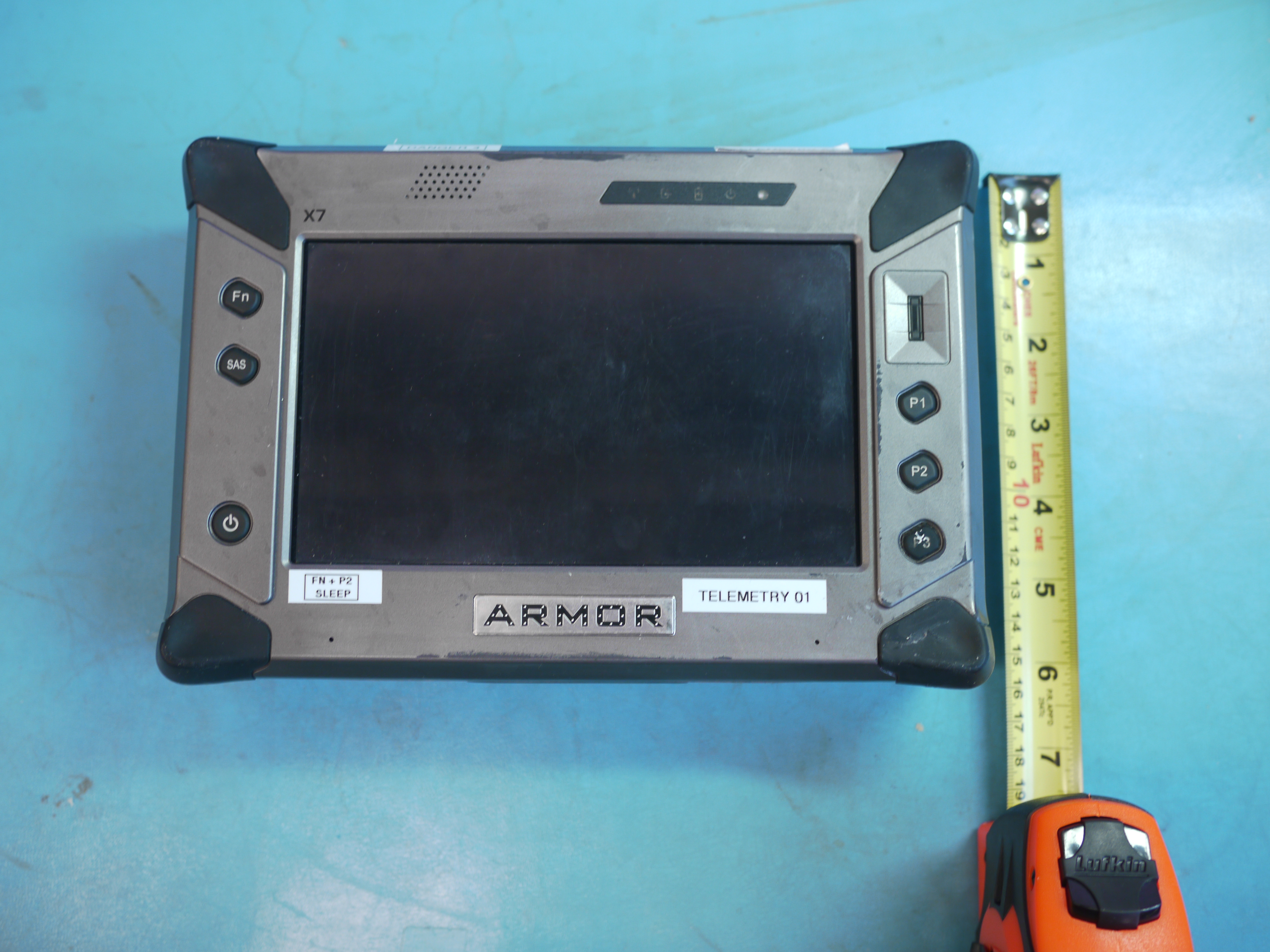
Wait, how big is it? The tablet is 8.9 " x 5.9 " and slightly less than 1.5" deep, with the batteries installed. The screen is recessed below the plastic overmold. to the top right is a fingerprint scanner along with 3 special-use buttons. These buttons can be used to get out of startup issues and around the 'start windows normally / safe mode' conditions. 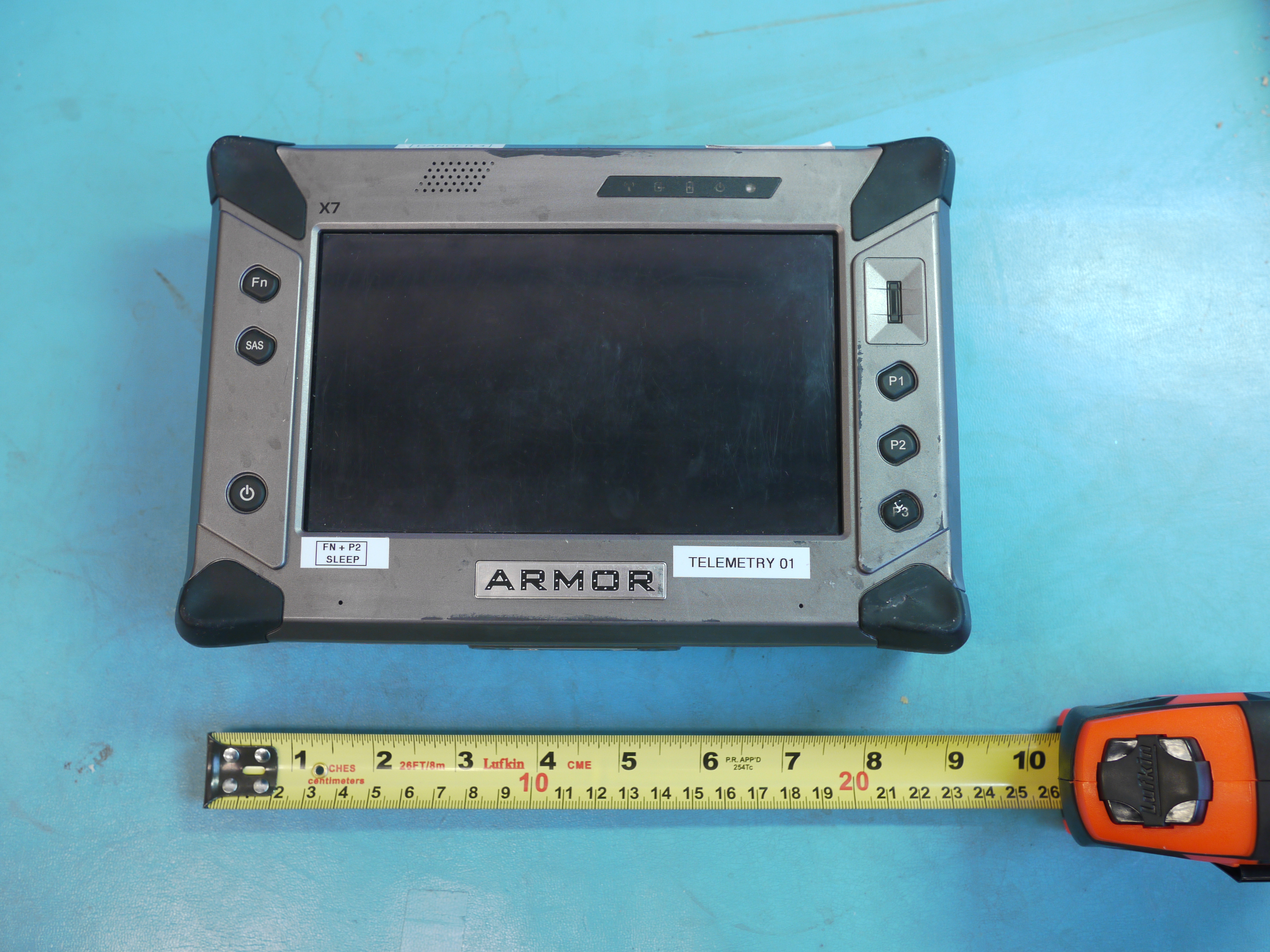
Removeable Batteries. Shown is the batteries in their removed state, a pushbutton permits a sliding latch which couples the batteries to the frame. The spring-loading on the sliding latch is sizeable and maintains a very tight mate from the battery pack plastic to the frame. 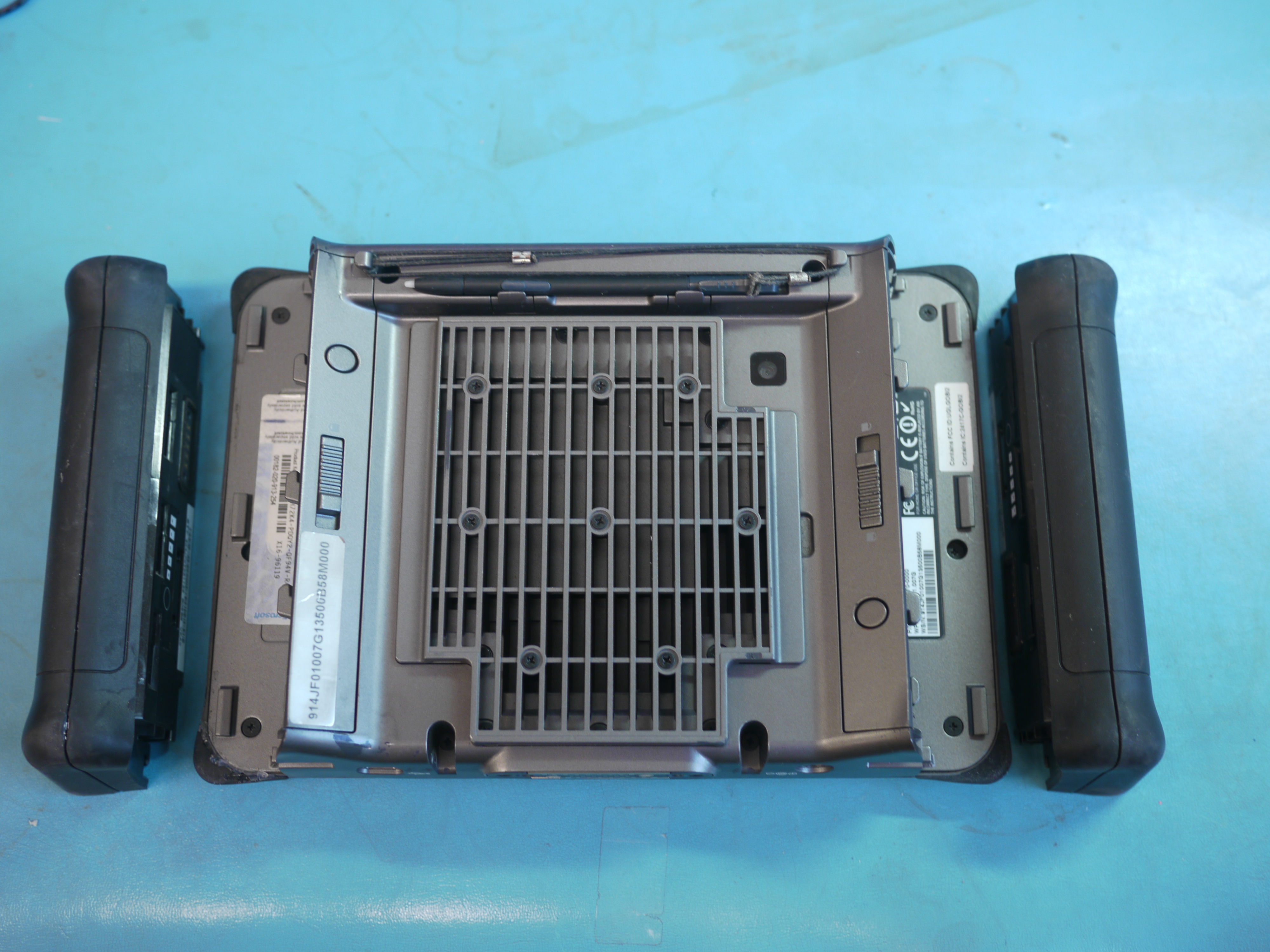
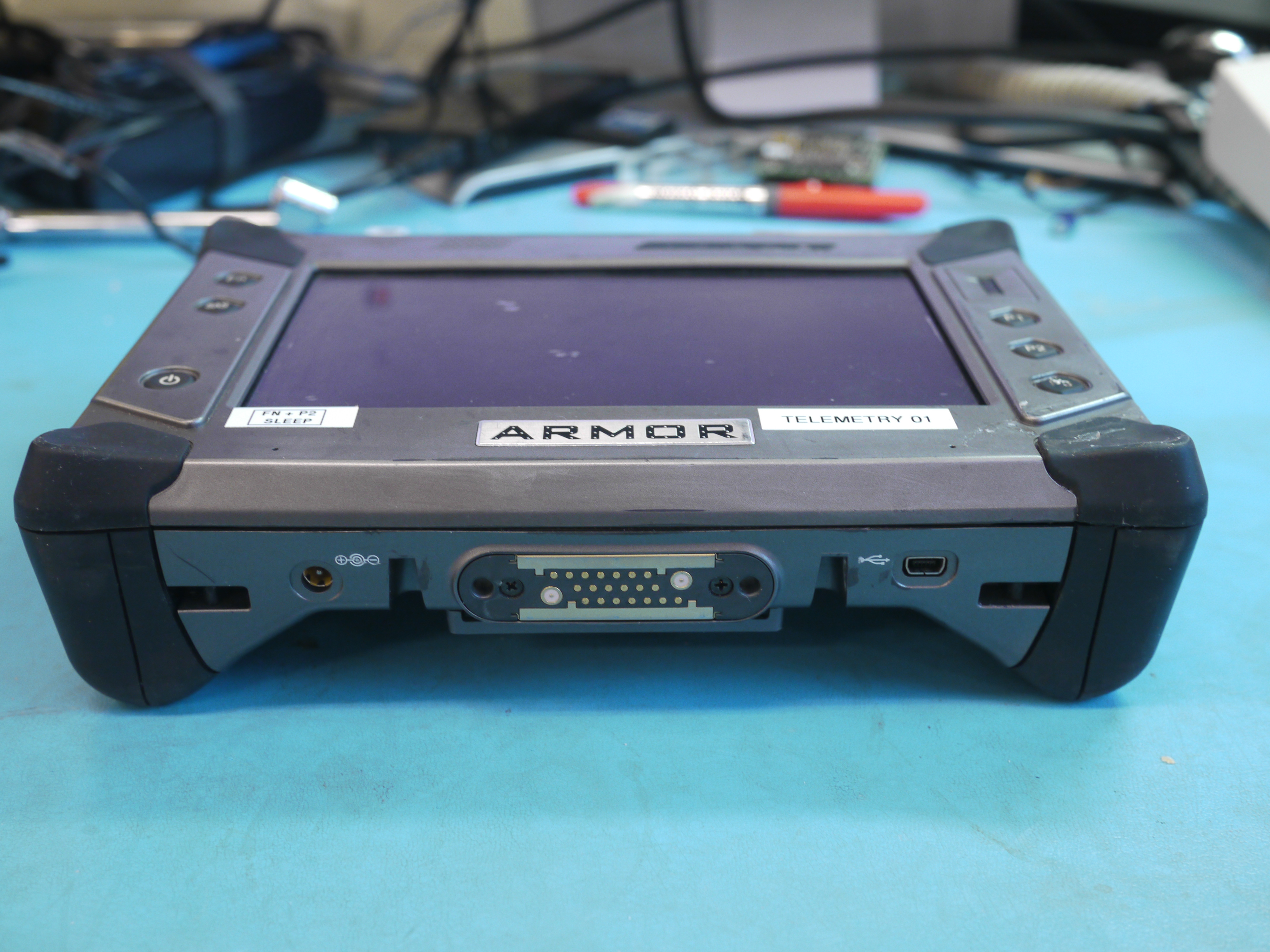
PORTS. The battery connects via a 9 position sprint loaded connector. Similar to pogo-pins, these transfer power and communictions to the battery module. A secondary connector is also available in one of the battery bays, this 'flexport' provides communications for external pheriphasl. 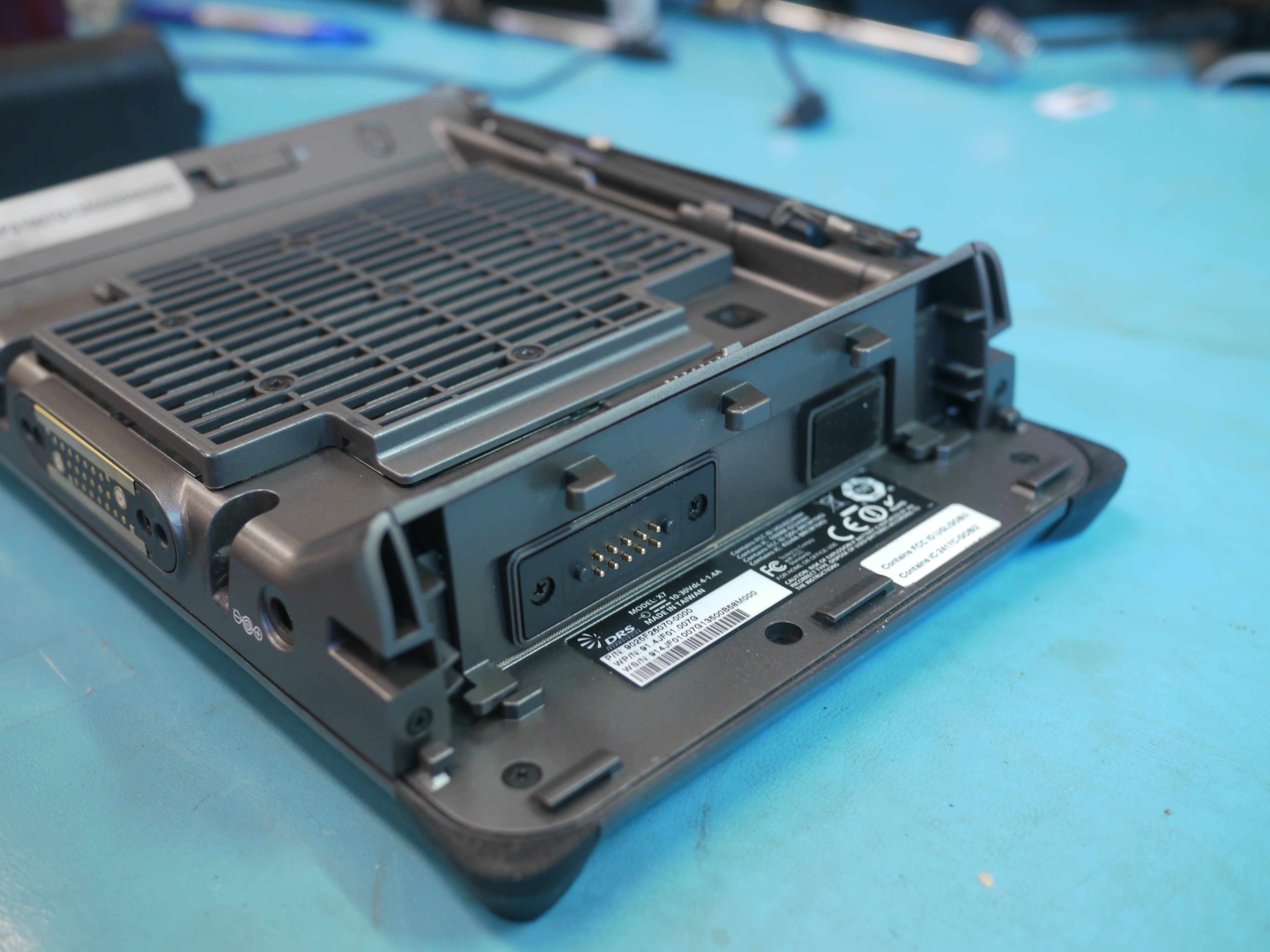
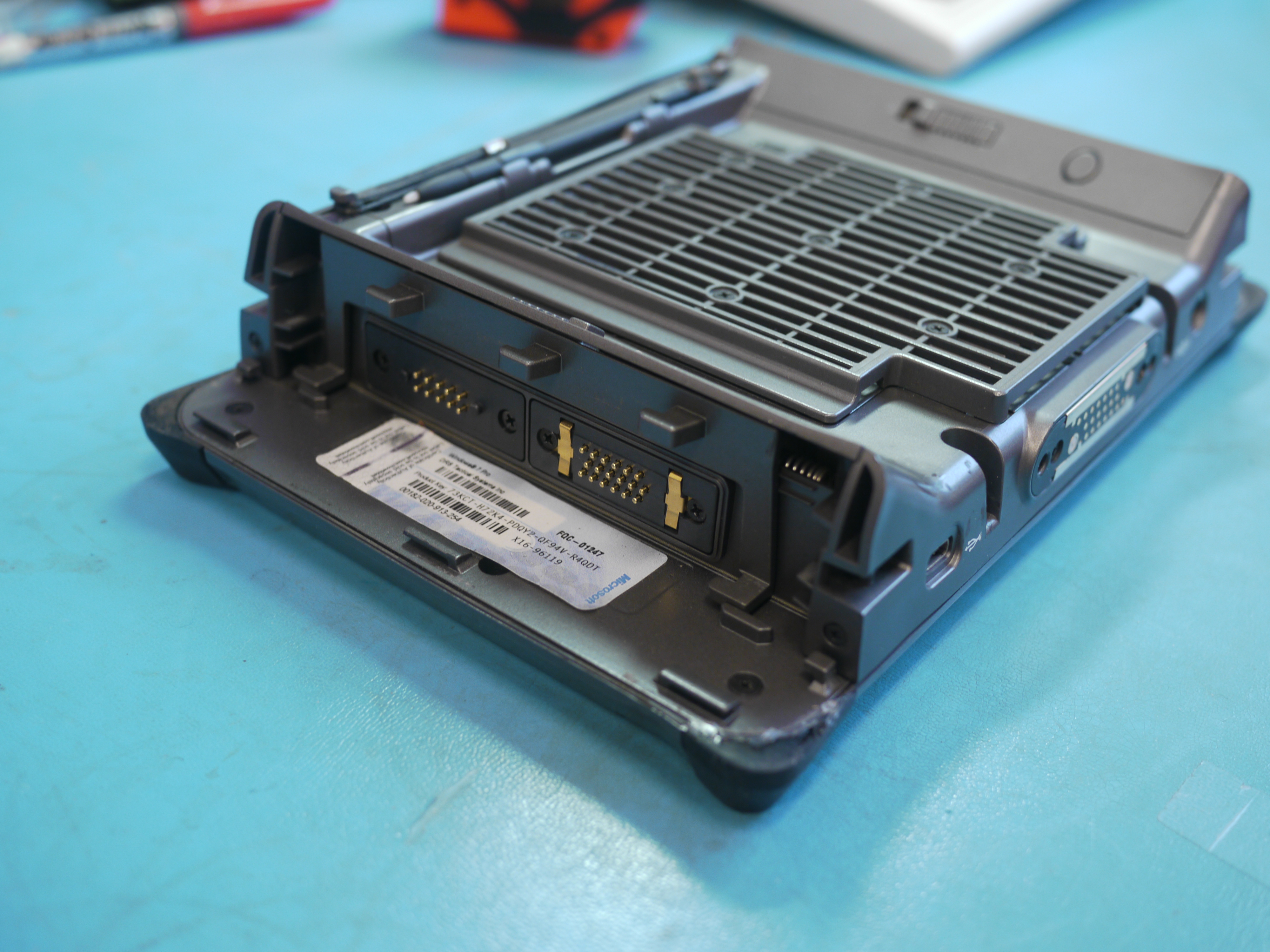
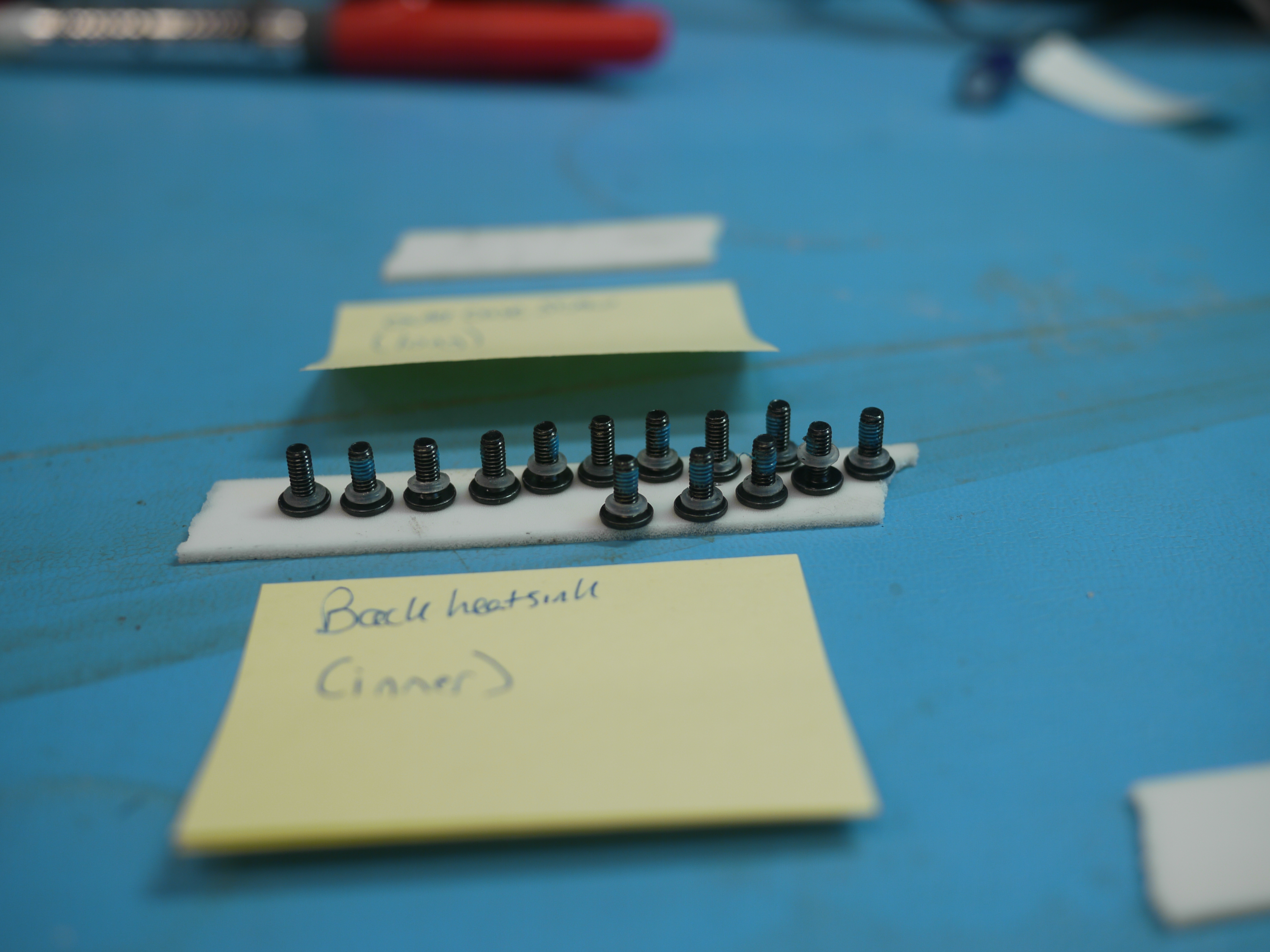
For the dissassembly, removed screws are asorted and labeled on small post-it notes. The back plane of the tablet has a finned heat spreader and a back plate which forms the watertight seal to the unit. Opening up we find a bunch of goodies. 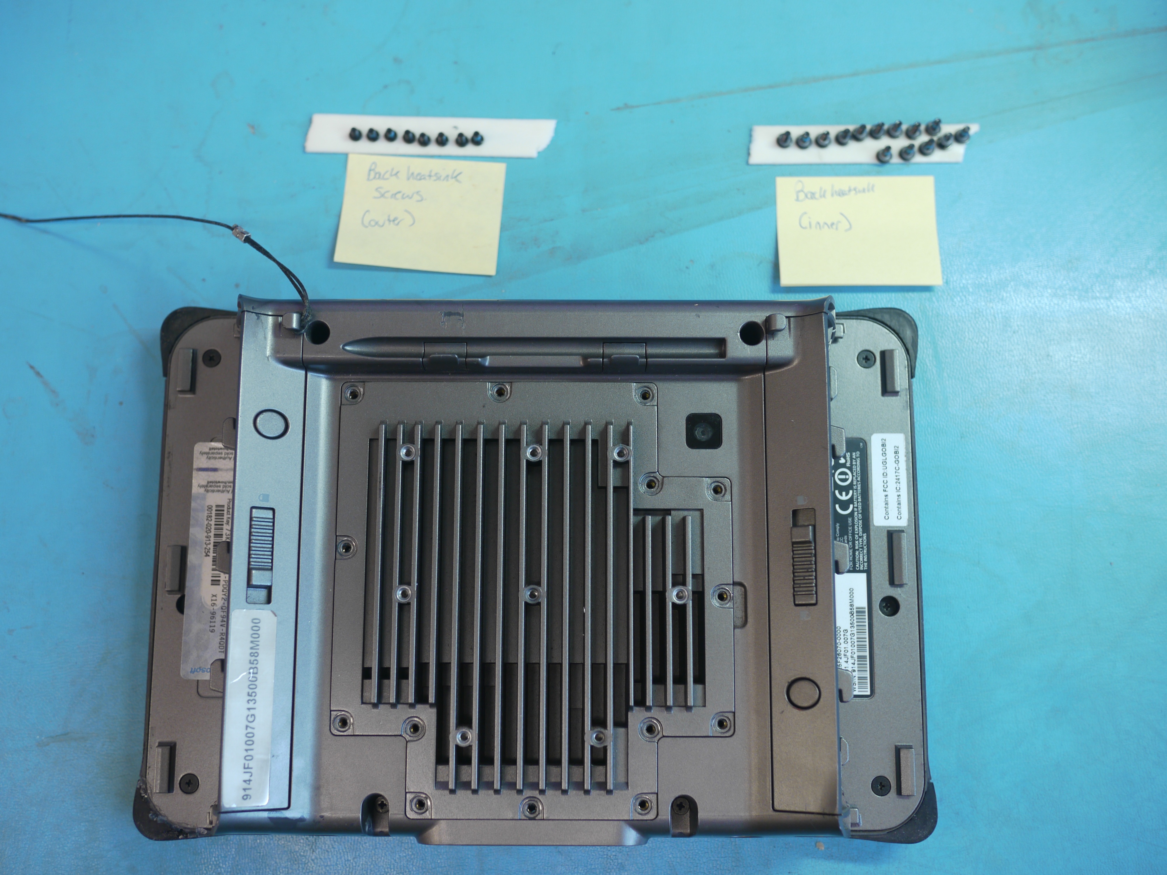
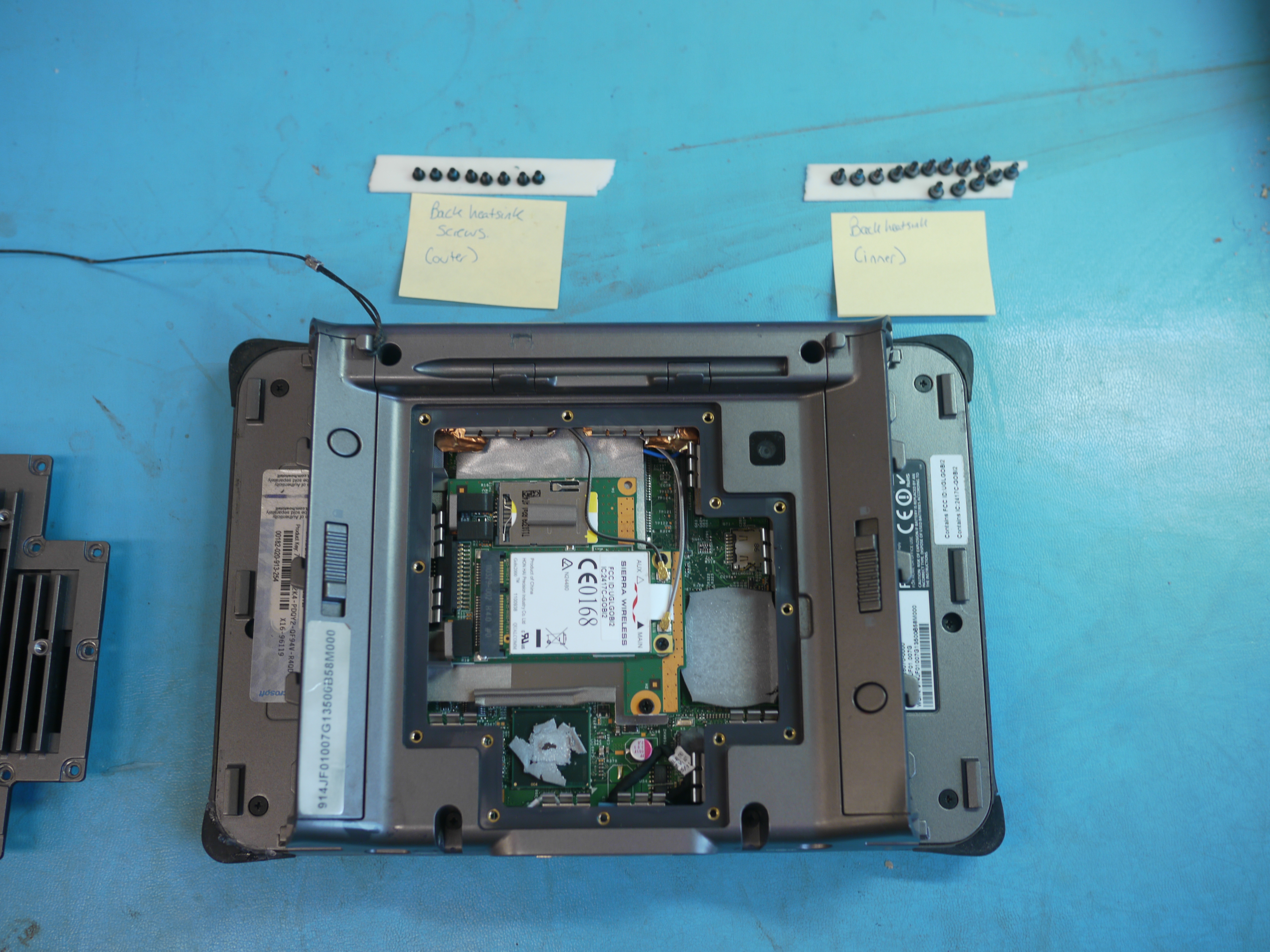
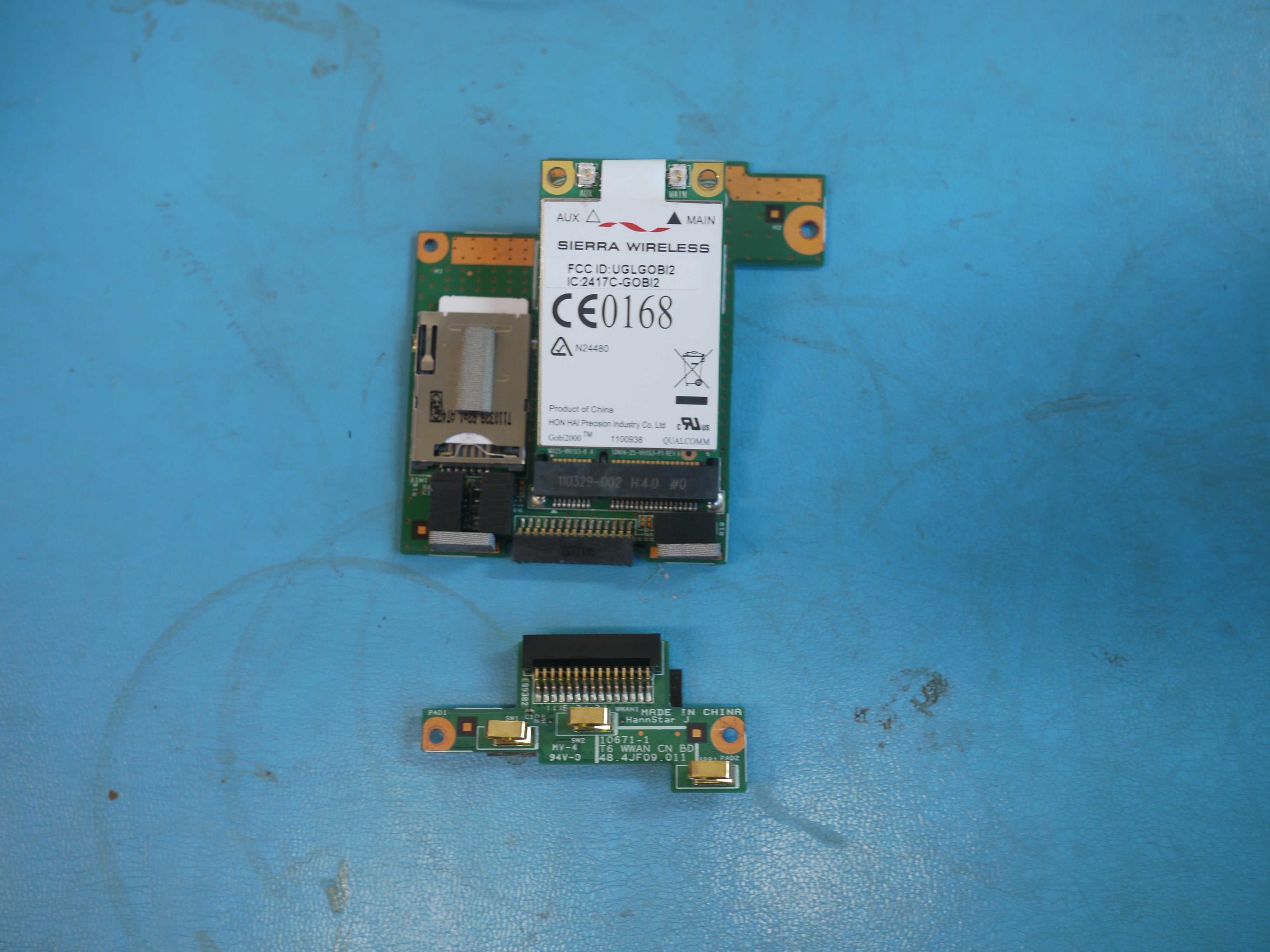
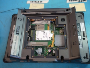
Here's a look inside, the backplate detaches and the whole battery-mating connector de-couples. There are a few interconnecting cables that mate the central control board to the perhipherals and connectors on the battery mating surface. A sierra wireless card [link] is also seen here, mating to the internal flex-port connector. This card is a fully functional GSM modem. 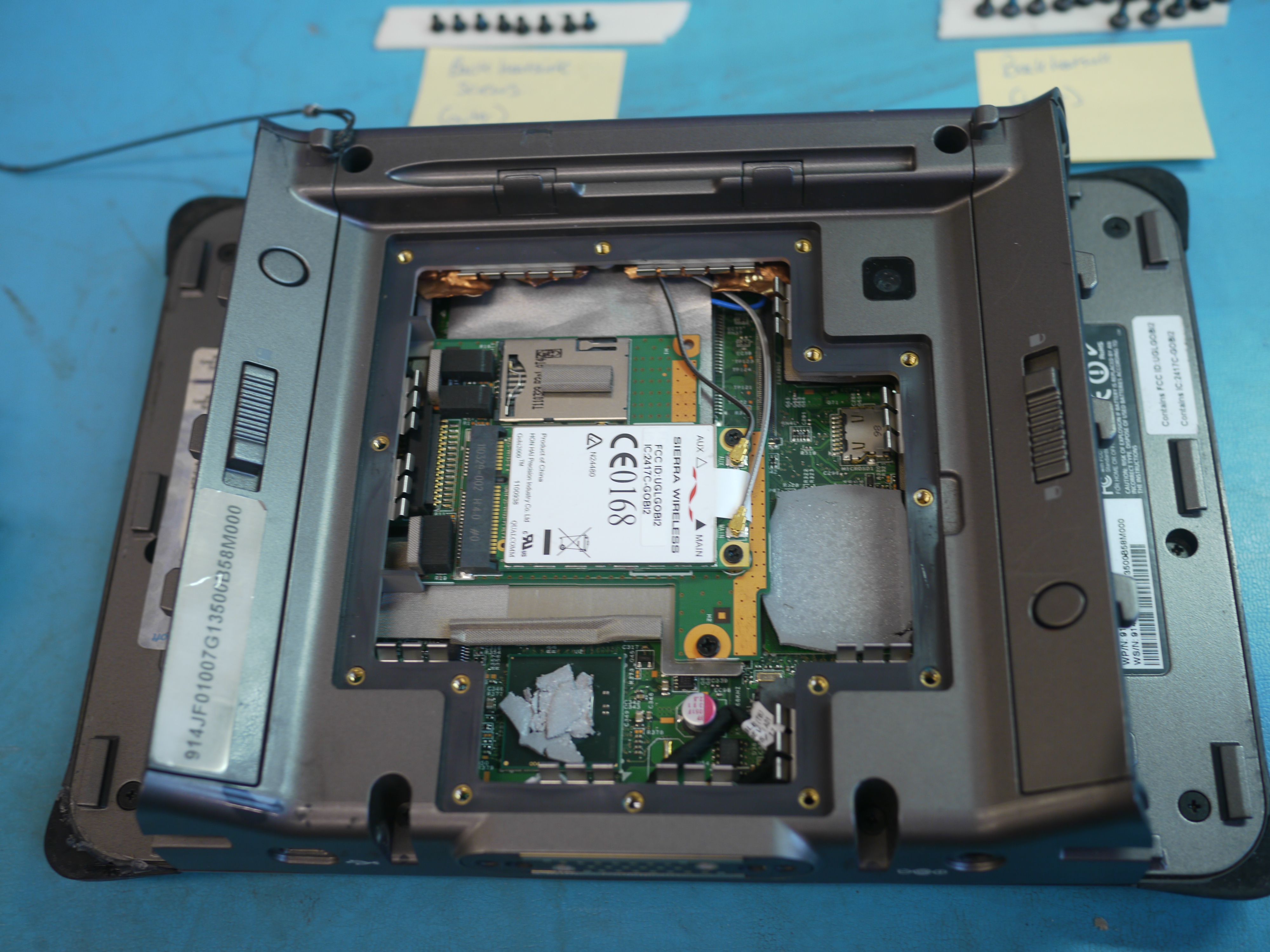
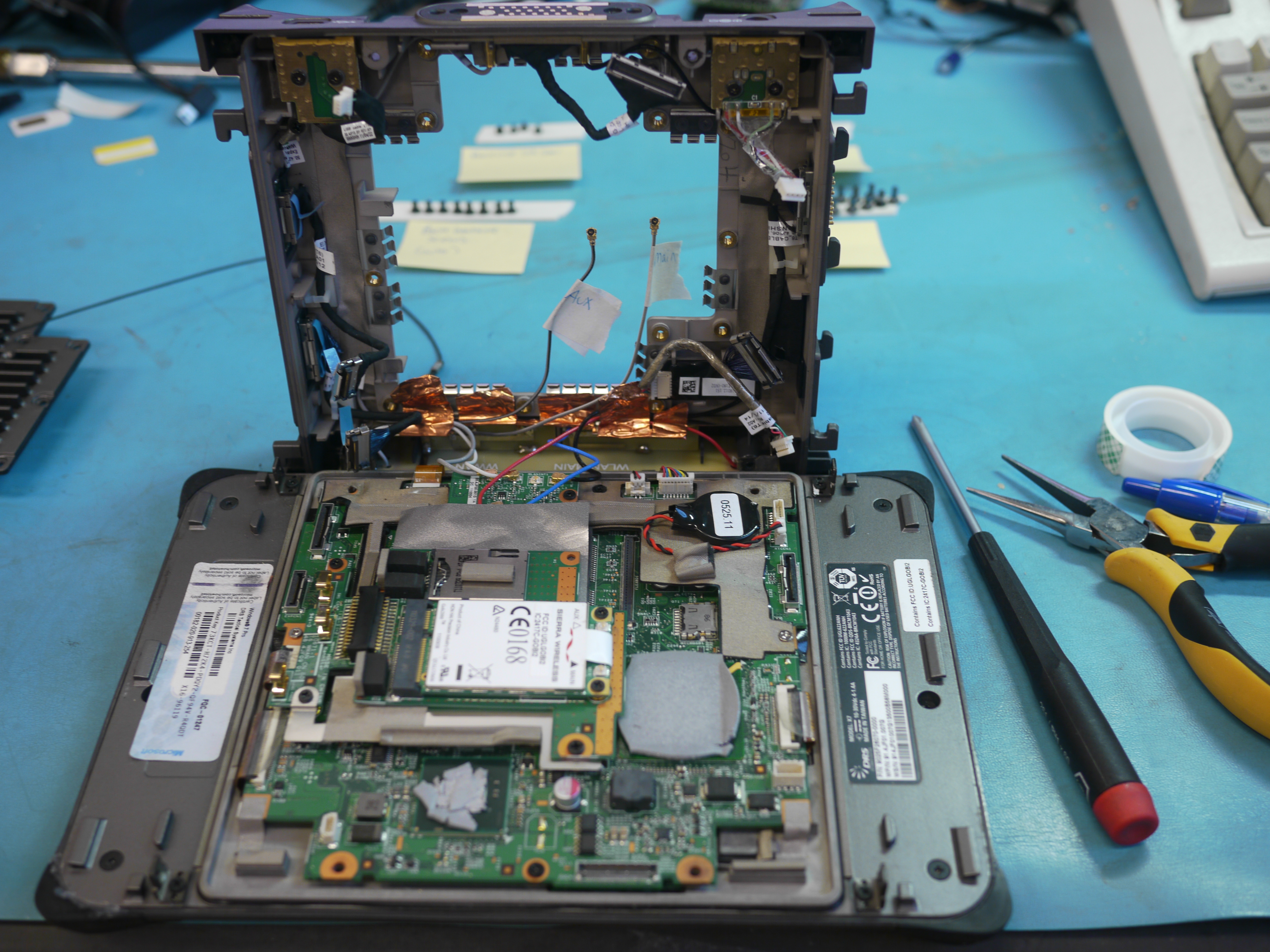
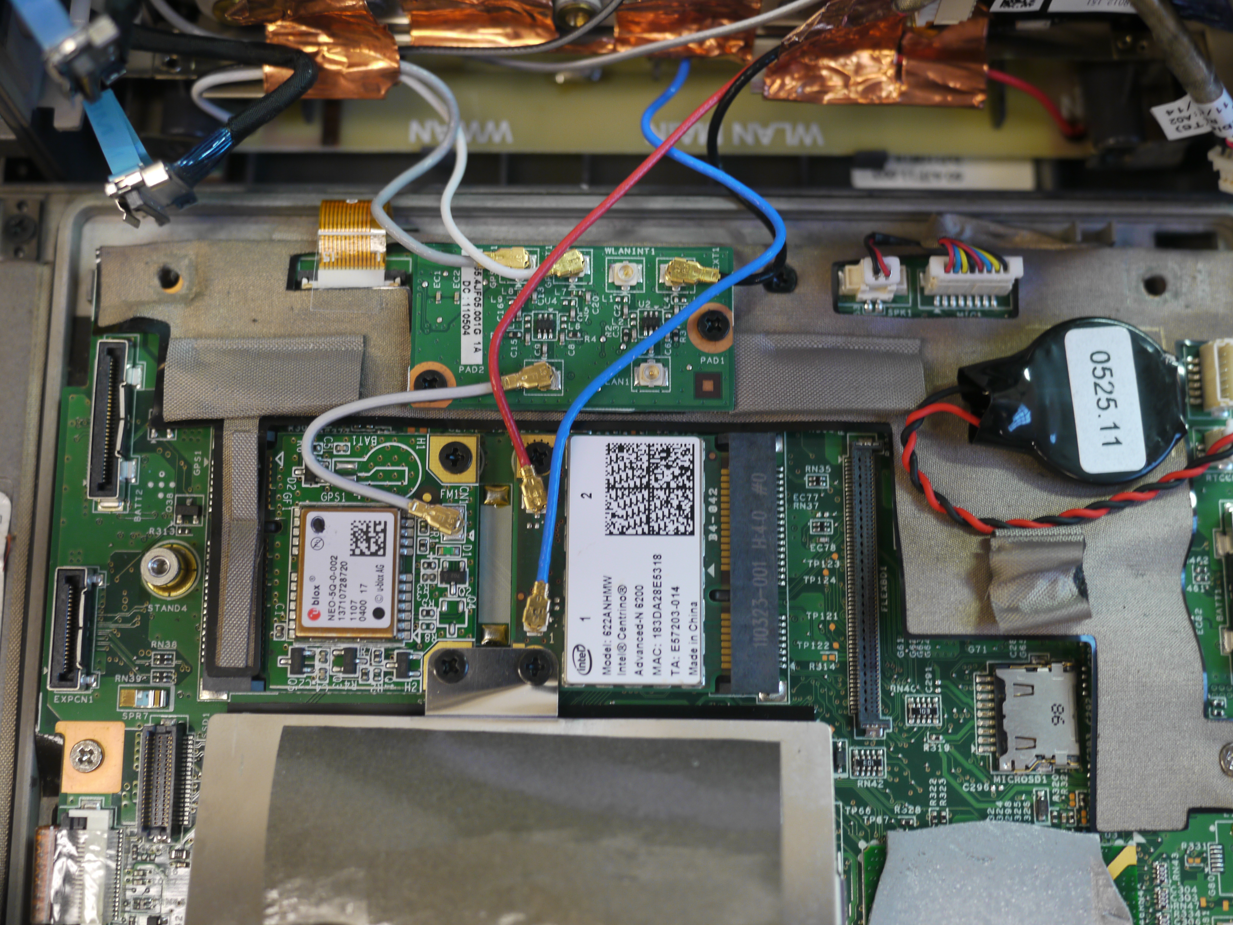
With the battery interface mechanicals removed and the gsm modem removed, a few more things become visible, the bios battery and antennas used for GPS and wifi are shown in the far top of the unit. Under the GSM modem and the aluminum flashing is a small intel wifi card [link] along with a u-blox GPS [link]. 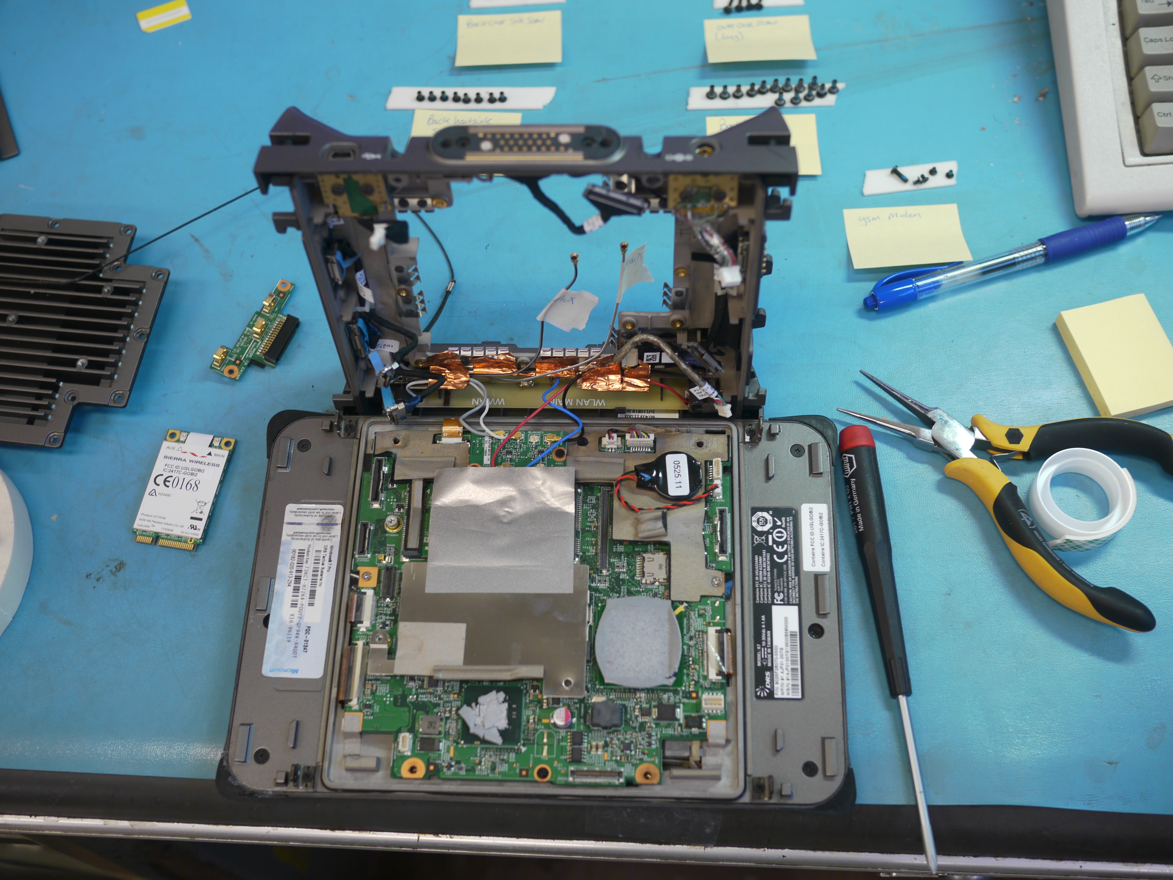
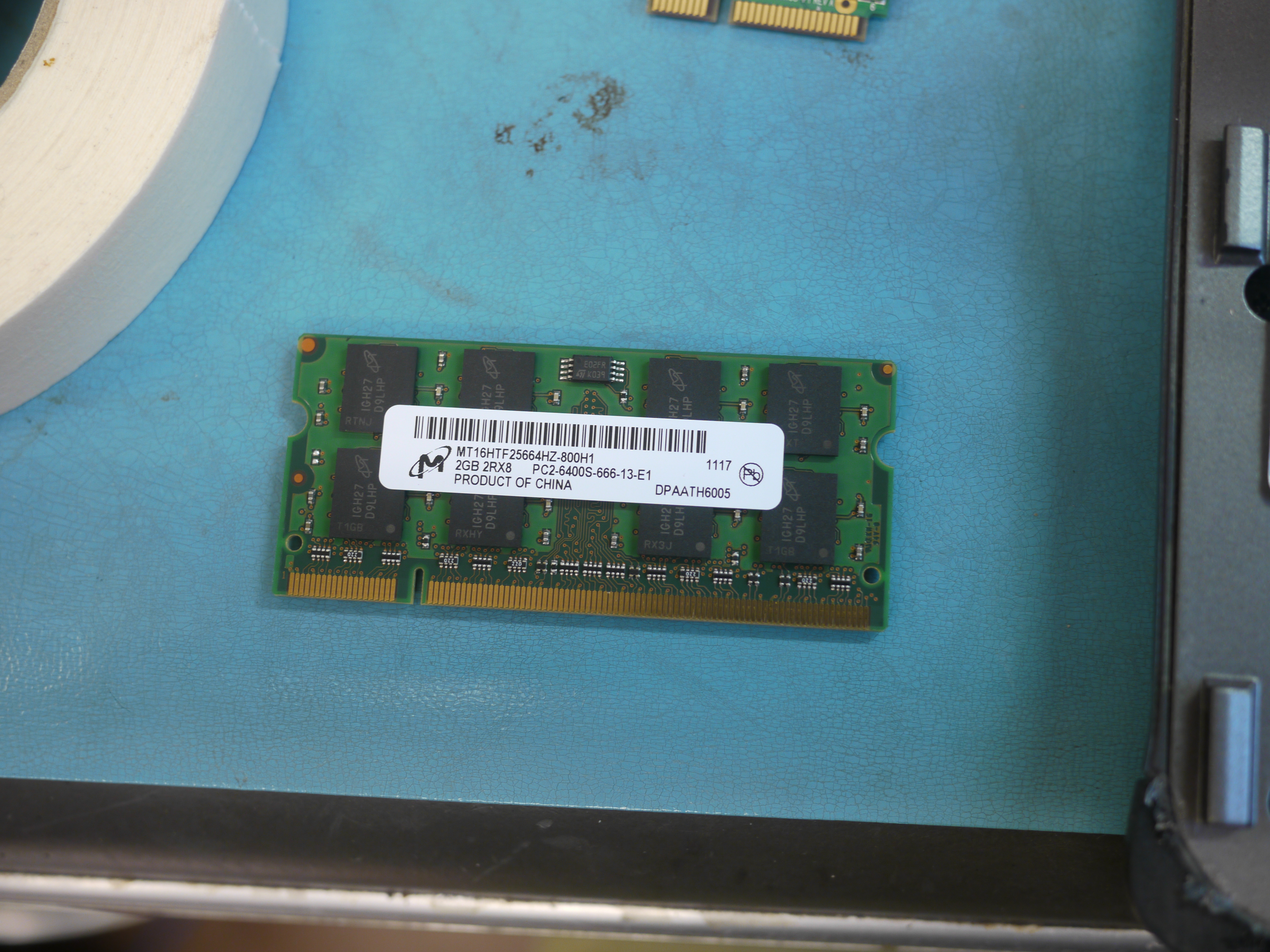
Behind the aluminum plating likes the system RAM, its a 2gb version of this [datasheet], note that higher than 2gb is an option, really just about any 200-Pin DDR2 SDRAM will fit. 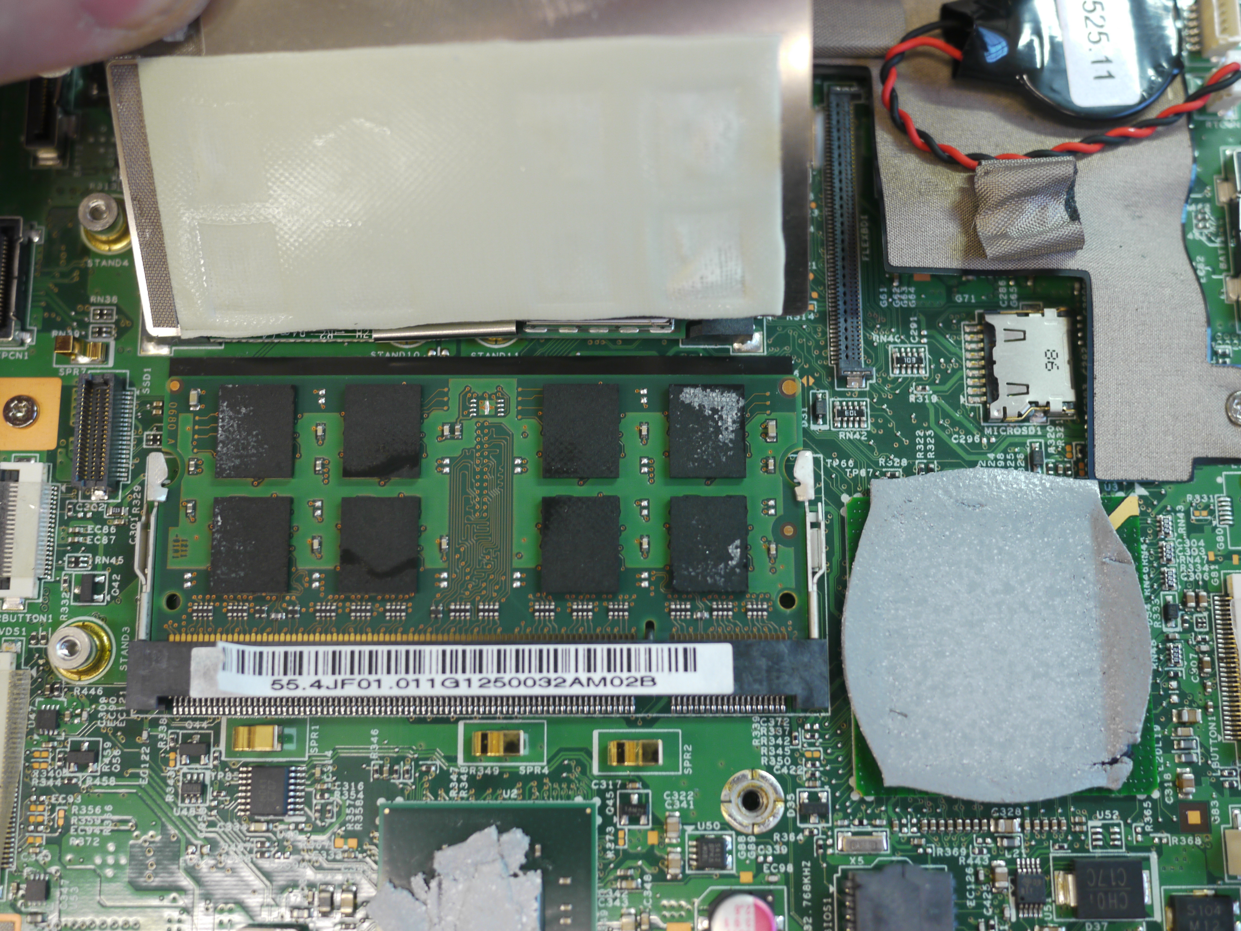
Here's a better look at the GSM module carrier board. note the flexspace connector on the front side. I will make some mechanical drawings of this part so its easier to mate other flex-space hardware in the same space. 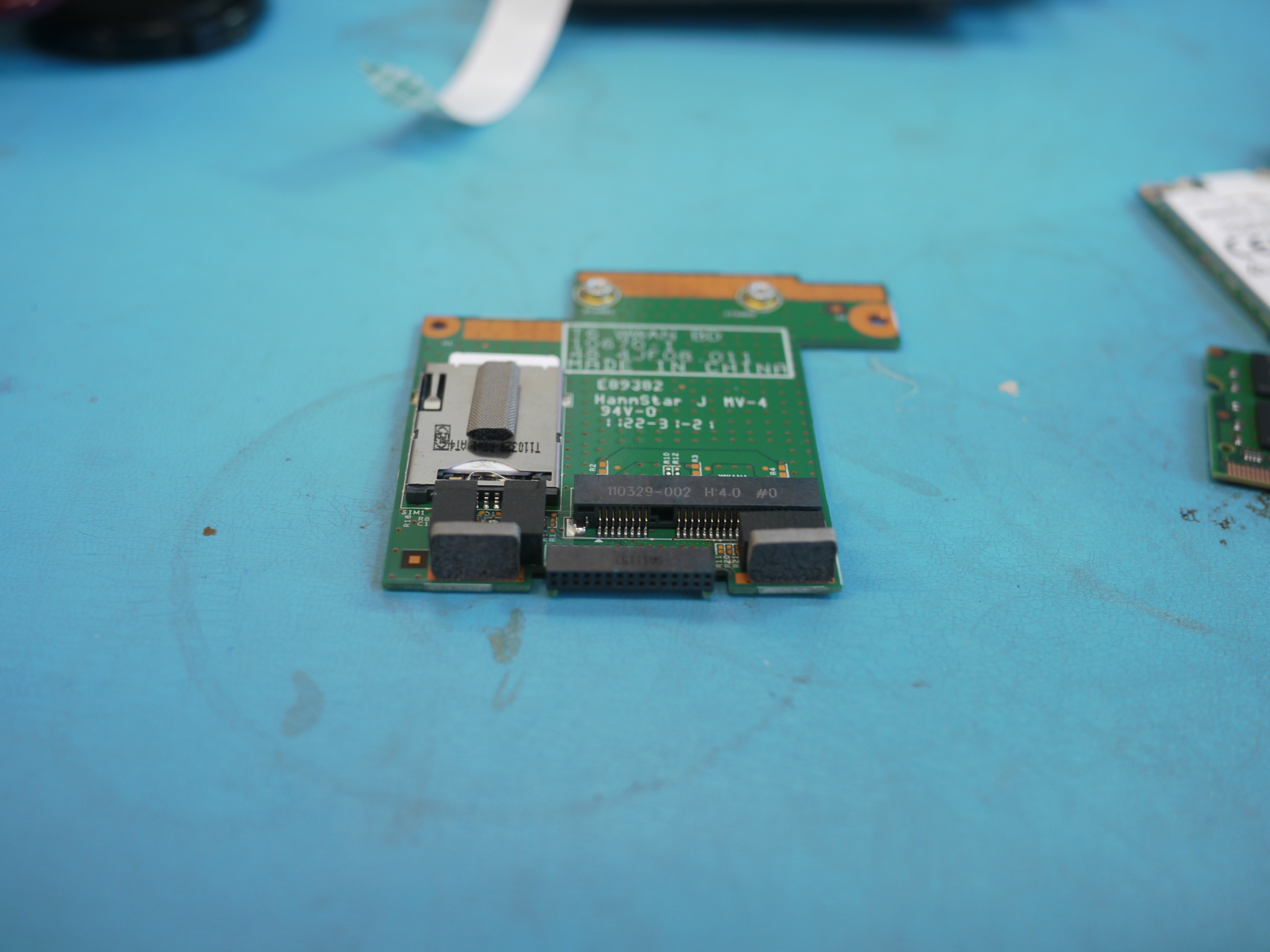
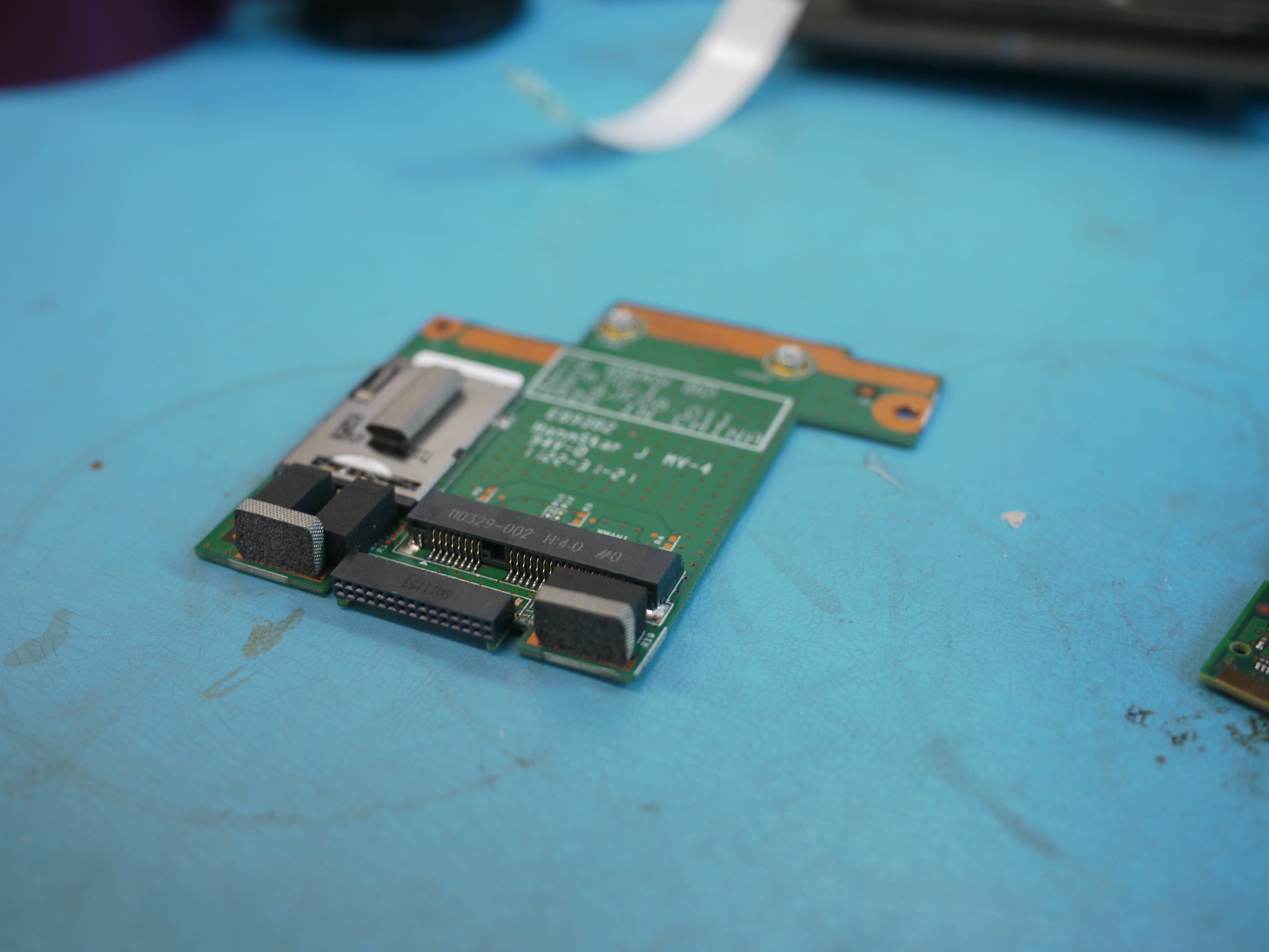
Here's the sierra wireless modem sitting next to an msata ssd. CURIOUS, this may be a quick update route for interal space! 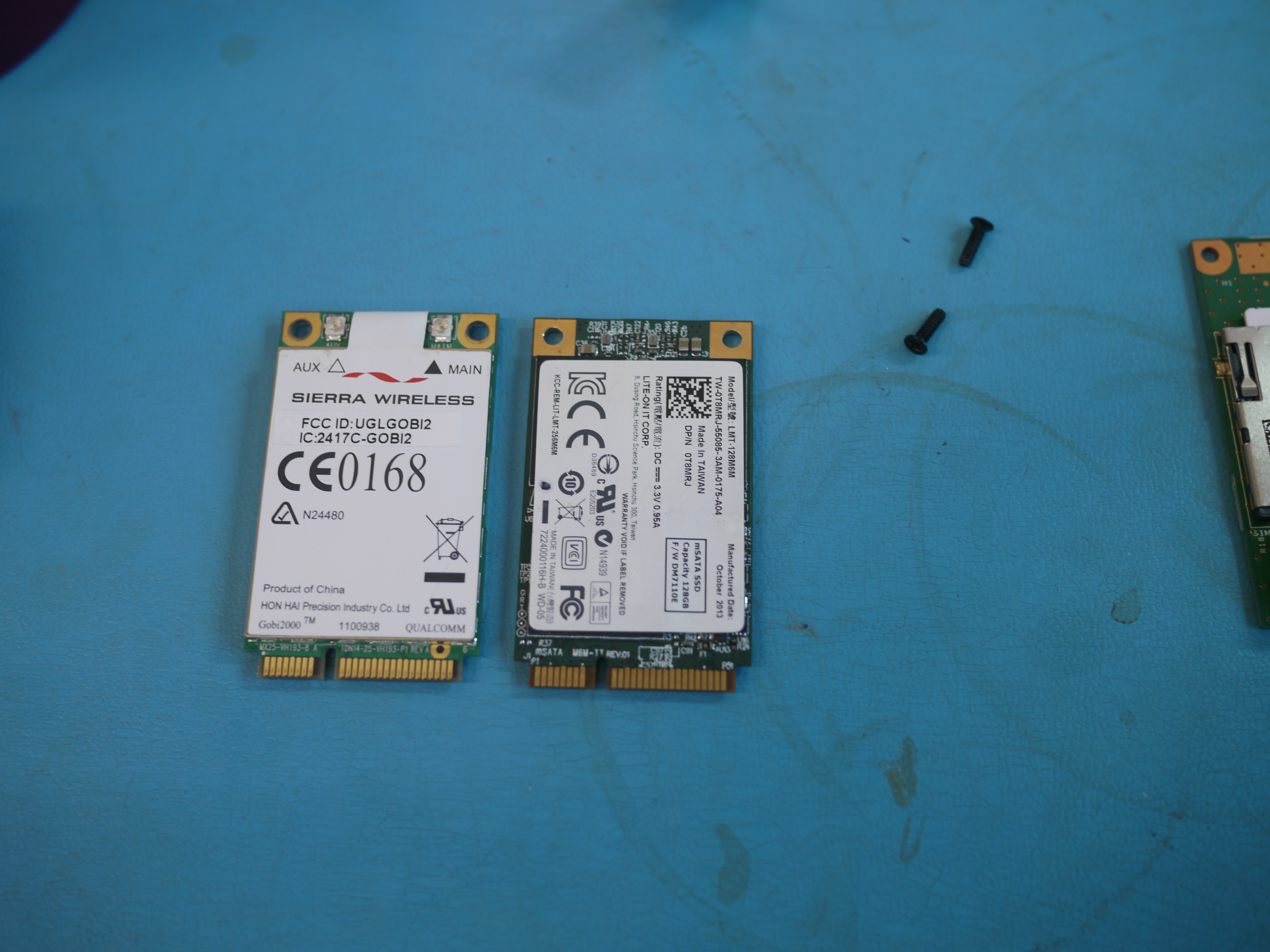
Finally *ALL* the screws sitting on doublesided tape to keep things from flying all over the plade during disassembly. 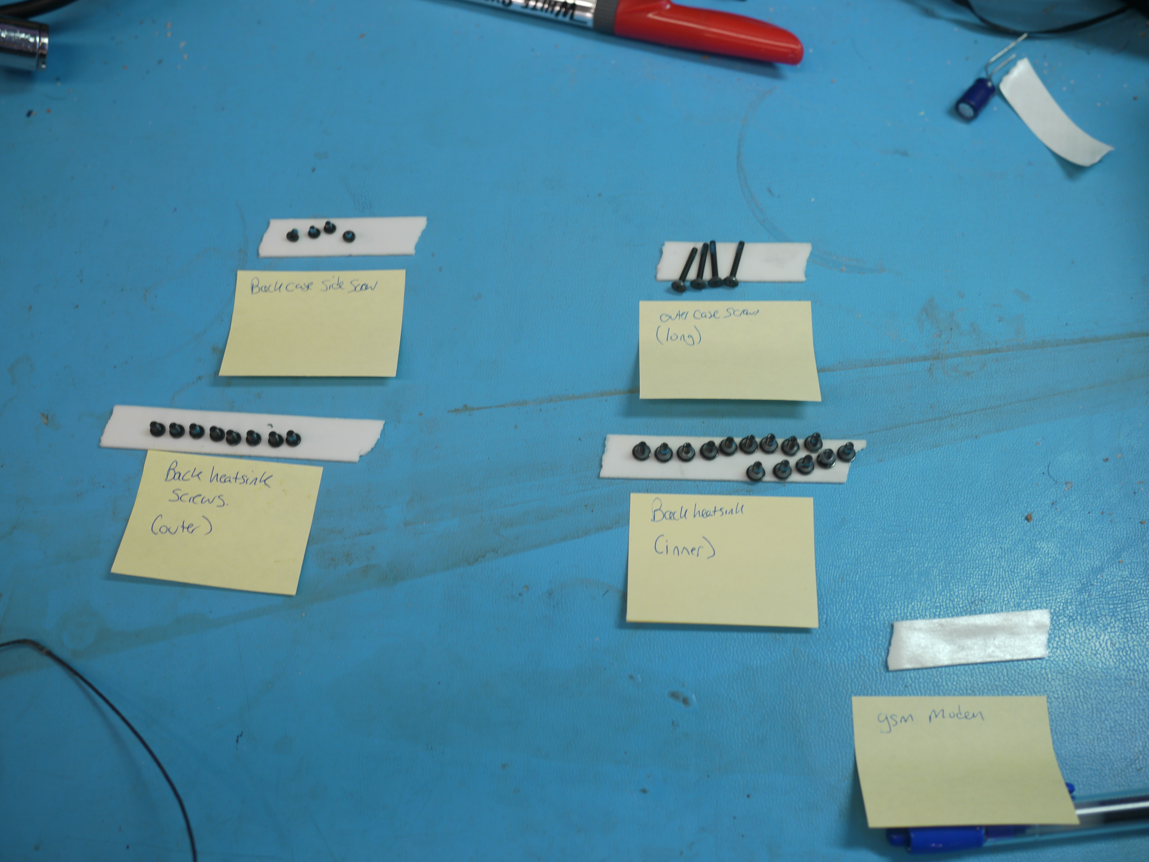
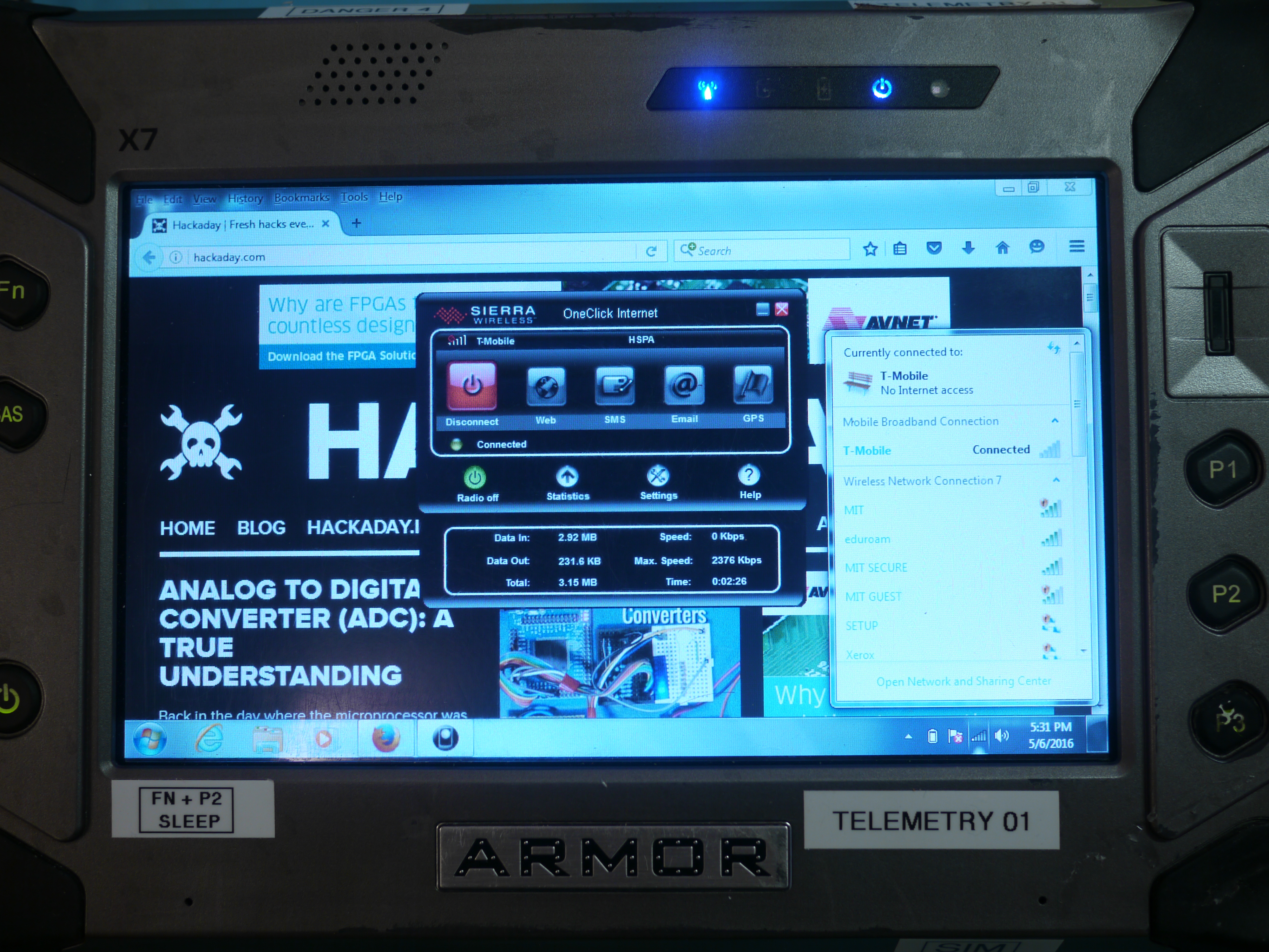
Wait, Is That a Cell Modem?The hardware connected to the internal flex-port appeared to be a GSM modem, i used an active GSM sim card and lo, DATA! Unfortunatley the unit uses odd external rf cable connectors, but this could be modifed if needed. Note, hackaday.com was loadable over cell-data using a T-Mobile sim card. 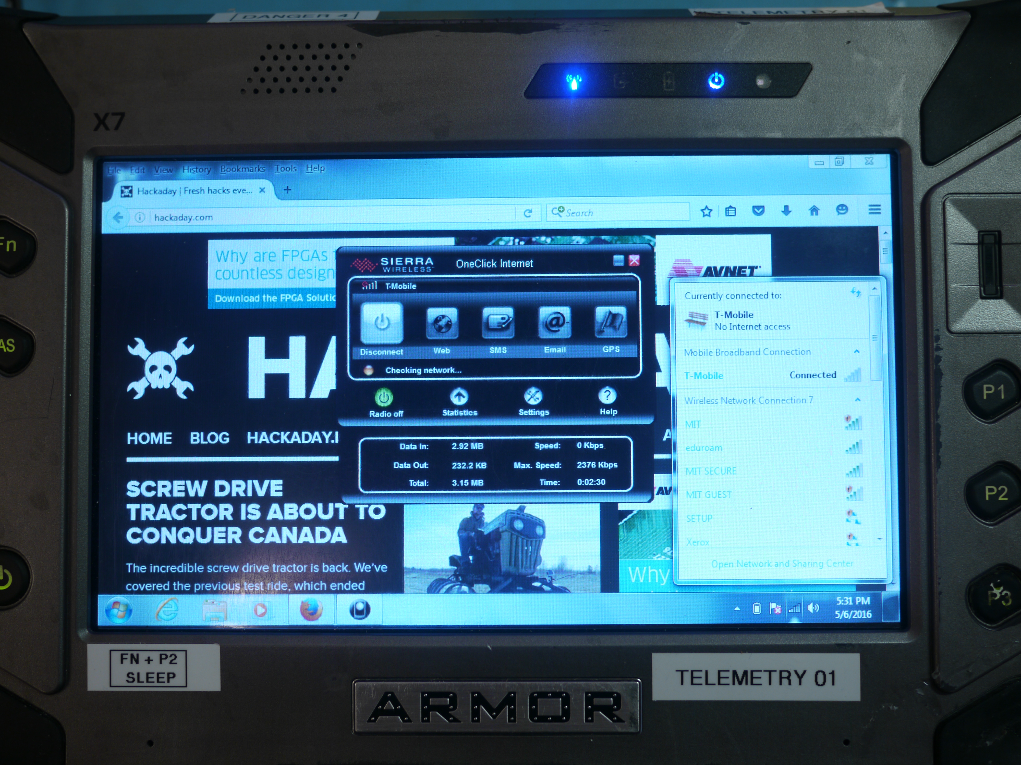
Concluding Remarks
Have you noticed that there are no advertisements or ridiculous pop ups?
Want More?
|
If you have questions or comments, ask below or send over an email.
Post your comments! |
|
Comment Box loading
|